
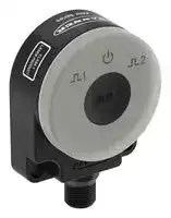


K50Z-FA2000KD-Q8
Multipoint Sensor, Time of Flight/Proximity, 2m Range, NPN/PNP, 5Pin M12 Connector, 30V, K50Z Series
- Manufacturer: BANNER ENGINEERING
- Product type:
- SVHC: No SVHC (23-Jan-2024)
- Product Range: K50Z Series
- Sensing Method: Time of Flight, Proximity
- Connection Method: 5 Pin M12 Connector
- Sensing Range Max: 2m
- Sensor Output Type: NPN / PNP
- Supply Voltage Max: 30V
- Supply Voltage Min: 10V
- Sensing Distance Max: 2m
- Supply Voltage DC Max: 30V
- Supply Voltage DC Min: 10V
| Delivery and price | |
|---|---|
| Units per pack | 50 |
| Price | 492.78 € |
| Current stock | 10+ |
| Lead time | 30 days |
## K50Z Multipoint Sensor Instruction Manual

**==> picture [464 x 368] intentionally omitted <==**

Original Instructions p/n: 239895 Rev. C June 04, 2024 © Banner Engineering Corp. All rights reserved.

## Contents

## **Chapter 1 Product Description**

Models ........................................................................................................................................................................................................... 3 Overview........................................................................................................................................................................................................ 3 Features and Indicators................................................................................................................................................................................. 4 Laser Description and Safety Information ..................................................................................................................................................... 4 Banner Measurement Sensor Software ........................................................................................................................................................ 4

## **Chapter 2 Installation Instructions**

Installation Best Practices ............................................................................................................................................................................. 5 Wiring............................................................................................................................................................................................................. 6 Mount the Device........................................................................................................................................................................................... 6

**Chapter 3 Getting Started** Install the Software ........................................................................................................................................................................................ 7 Connect to the Sensor................................................................................................................................................................................... 7 Software Overview ........................................................................................................................................................................................ 8

## **Chapter 4 Banner Measurement Sensor Workspace**

Navigation Toolbar......................................................................................................................................................................................... 9 Observation Space...................................................................................................................................................................................... 10 Observation Legend .................................................................................................................................................................................... 10 Summary Pane.............................................................................................................................................................................................11 Sensor Settings Pane...................................................................................................................................................................................11 General Tab ...........................................................................................................................................................................................11 Discrete 1 Tab....................................................................................................................................................................................... 12 Discrete 2 Tab....................................................................................................................................................................................... 12 Live Sensor Data Controls........................................................................................................................................................................... 13

**Chapter 5 Configuring a Sensor** Banner Measurement Sensor Software ...................................................................................................................................................... 14 Remote Input ............................................................................................................................................................................................... 14 Remote Setup....................................................................................................................................................................................... 14 IO-Link Interface .......................................................................................................................................................................................... 16 Reset the Sensor to Factory Defaults.......................................................................................................................................................... 16 Factory Default Settings ....................................................................................................................................................................... 17

**Chapter 6 Specifications** FCC Part 15 Class A for Unintentional Radiators........................................................................................................................................ 19 Industry Canada ICES-003(A)..................................................................................................................................................................... 19 PC Requirements ........................................................................................................................................................................................ 20 Dimensions.................................................................................................................................................................................................. 20 Field of View Charts..................................................................................................................................................................................... 21

## **Chapter 7 Update the Software............................................................................................ 22**

**Chapter 8 Accessories** Configuration Tools...................................................................................................................................................................................... 23 Cordsets ...................................................................................................................................................................................................... 23 Brackets....................................................................................................................................................................................................... 24 **Chapter 9 Product Support** Clean with Compressed Air ......................................................................................................................................................................... 25 Repairs ........................................................................................................................................................................................................ 25 Contact Us................................................................................................................................................................................................... 25 Banner Engineering Corp. Software Copyright Notice ................................................................................................................................ 25 Banner Engineering Corp Limited Warranty................................................................................................................................................ 25

K50Z Multipoint Sensor Instruction Manual

## Chapter Contents

**==> picture [500 x 44] intentionally omitted <==**

**----- Start of picture text -----**<br>
|||
|---|---|
|Models.................................................................................................................................................................................................................. 3|
|Overview .............................................................................................................................................................................................................. 3|
|Features and Indicators........................................................................................................................................................................................ 4|
|Laser Description and Safety Information ............................................................................................................................................................ 4|
|Banner Measurement Sensor Software|............................................................................................................................................................... 4|

**----- End of picture text -----**<br>


## Chapter 1

## Product Description

## Wide area height and presence measurement sensor. Patent pending.

- 3D Time of Flight technology to measure nearest distance and average distance of a target area

- Configurable sensing range up to 2-meter range with a wide, 45 × 45 degree field of view

- • Sensor monitors entire sensing region of interest, not a single point like an ultrasonic or laser sensor

- • Completely self-contained: no external lighting, controller, or PC required • Compact IP67 housing designed for industrial environments • Available with dual discrete outputs and IO-Link for advanced configuration and diagnostics

## WARNING:

- Do not use this device for personnel protection

- • Using this device for personnel protection could result in serious injury or death. • This device does not include the self-checking redundant circuitry necessary to allow its use in personnel safety applications. A device failure or malfunction can cause either an energized (on) or de-energized (off) output condition.

## WARNING:

- N'utilisez pas ce dispositif pour la protection du personnel.

- L'utilisation de ce dispositif pour la protection du personnel pourrait entraîner des blessures graves ou mortelles.

- Ce dispositif n'est pas équipé du circuit redondant d'autodiagnostic nécessaire pour être utilisé dans des applications de protection du personnel. Une panne ou un dysfonctionnement du dispositif peut entraîner l'activation ou la désactivation de la sortie.

## Models

**==> picture [487 x 33] intentionally omitted <==**

**----- Start of picture text -----**<br>
|||||||
|---|---|---|---|---|---|
|Models|Detection Range|Supply Voltage|Output|Resolution|Field of View|
|Dual Discrete (NPN/PNP),|
|K50Z-FA2000KD-Q8|20 mm to 2 m|10 V DC to 30 V DC|8 × 8|45 × 45 degrees|
|Pulse Pro, IO link|

**----- End of picture text -----**<br>


## Overview

The K50Z is an optical sensor that operates on the principals of time-of-flight technology to measure many points in the field of view. These points are used to calculate and track meaningful values such as nearest distance or average distance. The sensor uses infrared light that is reflected back to an imager with 64 measurement points to evaluate targets in a large area. The sensor can be configured by IO-link or in the Banner Measurement Sensor software. It has two outputs that can be set up independently of one another.

June 04, 2024

page 3

© Banner Engineering Corp. All rights reserved.

K50Z Multipoint Sensor Instruction Manual

Product Description

## Features and Indicators

LED indicators provide ongoing indication of sensing status.

**==> picture [400 x 80] intentionally omitted <==**

**----- Start of picture text -----**<br>
||||||
|---|---|---|---|---|
|LED|Color and Quantity|Description|
|1|1|Power|One green|Power ON|
|2|Output 1, on the left|Two amber|Discrete output 1 status|
|2|3|
|i)|
|3|Output 2, on the right|Two amber|Discrete output 2 status|

**----- End of picture text -----**<br>


## Laser Description and Safety Information

## CAUTION:

- Return defective units to the manufacturer.

- Use of controls or adjustments or performance of procedures other than those specified herein may result in hazardous radiation exposure.

- Do not attempt to disassemble this sensor for repair. A defective unit must be returned to the manufacturer.

## CAUTION:

- Tout dispositif défectueux doit être renvoyé au fabricant.

- L'utilisation de commandes, de réglages ou de procédures autres que celles décrites dans le présent document peut entraîner une exposition dangereuse aux radiations.

- N'essayez pas de démonter ce capteur pour le réparer. Tout dispositif défectueux doit être renvoyé au fabricant.

Class 1 lasers are lasers that are safe under reasonably foreseeable conditions of operation, including the use of optical instruments for intrabeam viewing.

**CLASS 1** Complies with 21 CFR 1040.10 and 1040.11, except for deviations pursuant to Laser Notice **LASER PRODUCT** No. 56, dated May 8, 2019. Complies with IEC 60825-1:2014 and EN 60825-1:2014+A11:2021.

## Banner Measurement Sensor Software

## Use the Banner Measurement Sensor software to:

- Quickly configure the sensor

- • Easily monitor device status via the software • Visualize the application in real-time

- Make adjustments to sensor settings on the fly

For more information, visit www.bannerengineering.com/us/en/products/sensors/software/ banner-measurement-sensor-software.html.

June 04, 2024

page 4

© Banner Engineering Corp. All rights reserved.

K50Z Multipoint Sensor Instruction Manual

## Chapter Contents

Installation Best Practices .................................................................................................................................................................................... 5 Wiring ................................................................................................................................................................................................................... 6 Mount the Device ................................................................................................................................................................................................. 6

## Chapter 2 Installation Instructions

## Installation Best Practices

For most applications, mount the sensor perpendicular to the target area and as close to center as possible. If perpendicular mounting is not possible, keep the mounting angle to a minimum. When using a 3D ROI, a pixel is considered inside when the midpoint has crossed into the 3D ROI area. For this reason, it is best practice to slightly under size the 3D ROI away from container edges or walls.

**==> picture [107 x 8] intentionally omitted <==**

**----- Start of picture text -----**<br>
Detection Position: Side View<br>**----- End of picture text -----**<br>


**==> picture [387 x 25] intentionally omitted <==**

**----- Start of picture text -----**<br>
Detection Position: Overhead View<br>A B C<br>**----- End of picture text -----**<br>


A = Pixel one detected; pixel two not detected because mid-point is outside the 3D ROI, pixel three not detected because it is out of the 3D ROI (see "Discrete 1 Tab" on page 12)

B = Pixels one and two detected because both midpoints are inside the 3D ROI; pixel three is not detected because it is outside of the 3D ROI

C = Pixels one, two, and three detected because the target is closer and all pixel midpoints are inside the 3D ROI (see "Field of View Charts" on page 21)

June 04, 2024

page 5

© Banner Engineering Corp. All rights reserved.

K50Z Multipoint Sensor Instruction Manual

Installation Instructions

## Wiring

Quick disconnect wiring diagrams are functionally identical.

**==> picture [500 x 129] intentionally omitted <==**

**----- Start of picture text -----**<br>
Key:<br>Dual Discrete Output<br>1 = Brown<br>bn (1) + 2 = White<br>bu (3) 10–30 V DC– 3 = Blue4 = Black<br>bk (4) Load D1_Out/IO-Link 5 = Gray (Connect for use with remote input or<br>wh (2) Load D2_Out Banner Measurement Sensor software)<br>gy (5) Input 1<br>2<br>* Push-Pull output.  4<br>  User-configurable PNP/NPN setting.<br>3 5<br>NPN or PNP<br>**----- End of picture text -----**<br>


## Mount the Device

1. If a bracket is needed, mount the device onto the bracket.

2. Mount the device (or the device and the bracket) to the machine or equipment at the desired location. Do not tighten the mounting screws at this time.

3. Check the device alignment.

4. Tighten the mounting screws to secure the device (or the device and the bracket) in the aligned position.

June 04, 2024

page 6

© Banner Engineering Corp. All rights reserved.

K50Z Multipoint Sensor Instruction Manual

## Chapter Contents

Install the Software............................................................................................................................................................................................... 7 Connect to the Sensor.......................................................................................................................................................................................... 7 Software Overview ............................................................................................................................................................................................... 8

## Chapter 3

## Getting Started

## Install the Software

IMPORTANT: Administrative rights are required to install the Banner Measurement Sensor software.

1. Download the latest version of the software from www.bannerengineering.com.

2. Navigate to and open the downloaded file.

3. Click Install to begin the installation process.

4. Depending on your system settings, a popup window may appear prompting to allow Banner Measurement Sensor to make changes to your computer. Click Yes .

5. Click Close to exit the installer.

## Connect to the Sensor

- A = Pro Converter Cable (MQDC-506-USB)

- B = Splitter (CSB-M1251FM1251M)

- C = PC running Banner Measurement Sensor software D = K50Z

- E = Power Supply (PSW-24-1 or PSD-24-4)

- F = Optional 5-Pin to 5-Pin Double-Ended Cordset (ex. MQDEC3-515SS)

1. Connect the sensor to the Pro Cable. See "Configuration Tools" on page 23.

2. Connect the Pro Converter cable to the PC.

3. Open the Banner Measurement Sensor Software.

4. Go to Sensor › Connect on the Navigation toolbar.

The Connection screen displays.

5. Select the correct Sensor Model and Com Port for the sensor.

6. Click Connect .

The Connection screen closes and the sensor data displays.

June 04, 2024

page 7

© Banner Engineering Corp. All rights reserved.

K50Z Multipoint Sensor Instruction Manual

Getting Started

## Software Overview

Easy setup and configuration of range, sensitivity, and output using the Banner Measurement Sensor software and Pro Converter Cable.

**==> picture [141 x 7] intentionally omitted <==**

**----- Start of picture text -----**<br>
Banner Measurement Sensor Software<br>**----- End of picture text -----**<br>


1. Navigation toolbar— Use this toolbar to connect to the sensor, to save or load a configuration, or to reset to factory defaults

2. Observation Space—Shows the entire sensor field of view and displays different items as they are selected from the legend

3. Observation Legend—Select what is viewable on the 3D View tab, such as the switch point planes and regions of interest

4. Summary Pane—Displays the live outputs numerically and shows information about each discrete configuration

5. Sensor Settings pane— Set the sensor parameters in this pane

6.

   - Status bar—Shows whether the sensor is connected and if a software update is available

7. Live Sensor Data controls—Use these controls to record, pause, and play real-time sensor data, and to refresh the sensor connection

June 04, 2024

page 8

© Banner Engineering Corp. All rights reserved.

K50Z Multipoint Sensor Instruction Manual

## Chapter Contents

Navigation Toolbar................................................................................................................................................................................................ 9 Observation Space............................................................................................................................................................................................. 10 Observation Legend........................................................................................................................................................................................... 10 Summary Pane....................................................................................................................................................................................................11 Sensor Settings Pane..........................................................................................................................................................................................11 Live Sensor Data Controls ................................................................................................................................................................................. 13

## Chapter 4 Banner Measurement Sensor Workspace

## Navigation Toolbar

Use this toolbar to connect to the sensor, to save or load a configuration, or to reset to factory defaults.

From the File menu, the following options are available:

## Load Configuration

Load a configuration to the connected sensor. Use this option to set up multiple sensors with the same parameters. Save Configuration

Save a configuration to a desired location for future use.

## Reset Frequently Used Settings

Resets the software settings without changing the configuration of the attached sensor.

Exit

Exit the Banner Measurement Sensor software.

From the Sensor menu, the following options are available:

## Connect

Connect to the sensor.

## Disconnect

Disconnect from the sensor.

## Factory Reset

Select to perform a factory reset on the sensor. All custom parameters will be lost

From the Help menu, the following option is available:

## About

Select to view the software version number, the copyright notice, and the warranty.

June 04, 2024

page 9

© Banner Engineering Corp. All rights reserved.

K50Z Multipoint Sensor Instruction Manual

Banner Measurement Sensor Workspace

## Observation Space

The Observation Space displays the live data as the sensor sees it in real time. Up to sixty-four individual measurement points will be seen in the sensor’s field of view, and by default the sensor is using all of the data when reporting a measurement. What is displayed may change based on user selections from the legend.

## 3D View Tab

Displays the 3D image of what the sensor sees. The entire sensor field of view can be seen, and the image changes when a target is presented.

To manipulate the 3D image, click and hold the left mouse button to rotate the image. Click and hold the right mouse button to pan the image. Rotate the wheel button to zoom in and out of the image. The Visual controls can also be used to move the image.

The two bar graphs represent Discrete 1 (red) and Discrete 2 (blue). The measurement displays on the graph as a moving bar. When the output is ON, the bar is green. When the output is OFF, the bar is grey. The solid red or blue lines represent switch points. The dashed lines represent the hysteresis values.

By default, the sensing direction is from top to bottom on the screen. Double-click a bar graph to flip the sensing direction and present as bottom to top of screen.

## 2D View Tab

Displays a 2D representation of all the pixels in the field of view of the sensor. There are two numbers in each pixel. The top number is the distance from the sensor, in millimeters. The bottom number is the excess gain.

Rotate the wheel button to zoom in and out of the image.

Click on an individual pixel to display the coordinate data and the excess gain in the lower right corner.

## Filter Pane

Use the Filter pane in the lower left corner to change how data is viewed on the 2D View and 3D View tabs. Pixel Filter : Select what pixel data to view in the Observation Space.

- All = All data

- Discrete1 = Only pixels in the active sensing zone of discrete 1

- • Discrete2 = Only pixels in the active sensing zone of discrete 2

- D1 or D2 = Pixels in either the active sensing zone of discrete 1 or discrete 2

- • None = No pixel data is displayed

Colorization : Select the variable to base the color of the pixel on. The options are:

- Excess Gain

- Distance

Palette : Select the color scale to show in the Observation Space. The options are:

- RGB

- RB

- Grayscale

Excess Gain : Set a range from 1 to 50000. Available when Colorization is set to Excess Gain .

Distance (mm) : Set a range from1 mm to 2000 mm. Available when Colorization is set to Distance .

## Observation Legend

The Observation Legend controls what is displayed in the Observation Space of the 3D View tab. Red items relate to Discrete 1 and blue items relate to Discrete 2.

Select or clear the checkboxes to show or hide the information.

## Discrete Output

Displays everything associated with the respective output.

## Switch Point

Displays a solid plane where the switch point is located, or 2 planes if in window mode.

## Measured Value

Displays a translucent plane that tracks with the current sensor measurement.

## 3D ROI

Displays a customizable 3D box that represents the active sensing area for that output. The sensor will not account for pixels outside of this area for its measurement.

June 04, 2024

page 10

© Banner Engineering Corp. All rights reserved.

Banner Measurement Sensor Workspace

K50Z Multipoint Sensor Instruction Manual

## View X, Y, Z axis

Displays the X, Y, and Z axes with the origin at the face of the sensor.

## Sensor Field of View

Displays a grey representation of the full viewing area of the sensor.

## Visual controls

The Visual controls are located in the upper left corner. Click the arrow if they are not visible. Click the buttons to move and rotate the image in the Observation Space .

Click Reset View to reset the orientation of the image in the Observation Space .

## Summary Pane

The Summary pane (blue shaded area) displays Discrete 1 State/Discrete 2 State and Discrete 1 Measurement/Discrete 2 Measurement , which is either Average Distance or Nearest Distance .

## State

Displays whether the output is ON (green) or OFF (grey).

## Measurement

Displays the distance to the target, depending on the Measurement Mode used (see "Discrete 1 Tab" on page 12 and "Discrete 2 Tab" on page 12).

- If Average Distance is used, the distance is the average of all pixels in that output’s active sensing area

- If Nearest Distance is used, the distance is the closest measured point from the face of the sensor in the active sensing area

## Sensor Settings Pane

Set parameters for the sensor.

Click Read to read the current parameters of the connected sensor. Click Write to write the parameters to the sensor. Yellow highlight on a parameter's value indicates changes that have not yet been written to the sensor.

## General Tab

The following are the parameters on the General tab on the Sensor Settings pane.

## Resolution

The sensor can operate at two resolutions:

- Standard 8×8 :  Best for utilizing as much of the available sensor information as possible

- Reduced 4×4 :  Best for faster response time

## Response Speed

The available options depend on which resolution is selected.

- Fast : Operates as quickly as the sensor is able

- Medium : Reduces outlier measurements

- Slow : Longer shutter for improved repeatability and accuracy in low excess gain

**==> picture [483 x 67] intentionally omitted <==**

**----- Start of picture text -----**<br>
Speed (ms)<br>Resolution<br>Fast Medium Slow<br>Standard 8×8 140 270 500<br>Reduced 4×4 35 75 140<br>**----- End of picture text -----**<br>


Sensor Polarity

Define the output and remote input signal type.

## Sensor Lockout

Enable or disable the remote input wire.

June 04, 2024

page 11

© Banner Engineering Corp. All rights reserved.

K50Z Multipoint Sensor Instruction Manual

Banner Measurement Sensor Workspace

## Mounting Correction

Use the Pitch , Yaw , Roll sliders to apply a transform to the point cloud data to account for non-perpendicular mounting angles.

## Discrete 1 Tab

The following are the parameters on the Discrete 1 tab on the Sensor Settings pane.

## Measurement Mode

Nearest distance : The sensor responds to the closest target in the field of view.

Average distance : The sensor responds to the average pixel measurement over the entire active sensing area.

## Output Mode

Switch Point - Object Ref : Creates a single switch point with the hysteresis set farther away from the sensor. The output turns ON at the switch point, and OFF at the hysteresis.

Switch Point - Background Ref : Creates a single switch point with the hysteresis set closer to the sensor. The output turns ON at the hysteresis and OFF at the switch point.

Window : Creates two switch points forming window limits with the hysteresis on the outside of the window.

## Distance Settings

Define the switch point(s) and the hysteresis. Use either the sliders to manually define the switch point or the Teach button to automatically define the switch point.

Hysteresis Mode : Select User Defined or Dynamic . Selecting Dynamic automatically sets the hysteresis depending on the target measurement.

## Active Sensing Area

## 2D ROI

- Full Field : Uses the entire 8×8 (or 4×4) pixel area for measurement.

- Custom : Shows an ROI Map. Clicking individual pixels turns them on or off. Colored pixels are active, and white pixels are off. Drag to select a large number or pixels, then click the selection to turn the entire selection on or off.

## 3D ROI

- Full Field : Uses the entire 3D area for measurement.

- Custom : Defines three different dimensions in X, Y, and Z to create the active sensing area. This 3D area shows when the 3D ROI checkbox is selected in the Observation Legend . The sensor is located at point 0,0,0 and the dimensions are defined in relation to this origin.

## Output Settings

NO/NC : Select Normally Open or Normally Closed from the list.

On Delay : Set an on delay in milliseconds. The maximum time is 60,000 ms. Off Delay : Set an off delay in milliseconds. The maximum time is 60,000 ms.

## Response Time

Displays the response time set on the General tab under Response Speed .

## Discrete 2 Tab

The following are the parameters on the Discrete 2 tab on the Sensor Settings pane. This tab is available for dual discrete models.

## Measurement Mode

Nearest distance : The sensor responds to the closest target in the active sensing area.

Average distance : The sensor responds to the average measurement over the entire active sensing area.

## Output Mode

Switch Point - Object Ref : Creates a single switch point with the hysteresis set farther away from the sensor. The output turns ON at the switch point, and OFF at the hysteresis.

Switch Point - Background Ref : Creates a single switch point with the hysteresis set closer to the sensor. The output turns ON at the hysteresis and OFF at the switch point.

Window : Creates two switch points forming window limits with the hysteresis on the outside of the window. Complementary : Output 2 will be the opposite of Output 1.

Pulse Pro/PFM : PulsePro/PFM output to interface with Banner lights or a PLC with Pulse Frequency Modulated (PFM) inputs.

June 04, 2024

page 12

© Banner Engineering Corp. All rights reserved.

Banner Measurement Sensor Workspace

K50Z Multipoint Sensor Instruction Manual

## Distance Settings

Define the switch point(s) and the hysteresis. Use either the sliders to manually define the switch point or the Teach button to automatically define the switch point.

Hysteresis Mode : Select User Defined or Dynamic . Selecting Dynamic automatically sets the hysteresis depending on the target measurement.

## Pulse Pro/PFM Settings

## Available when Output Mode is set to Pulse Pro/PFM .

The K50Z can generate pulses whose frequency are proportional to the sensor's measured distance, thereby providing a method for representing an analog signal with only a discrete counter. The sensing range of the sensor is scaled from 100 Hz to 600 Hz. 100 Hz equals the near range limit of the sensor, and 600 Hz equals the far sensing range limit. An output of 50 Hz or 650 Hz (user defined in the software) represents a loss of signal condition where there is no target or the target is out of range. This output can be tied directly to a number of Banner lights for visual feedback without the need for a controller.

100 Hz: Define the near sensing range limit of the Pulse Pro range.

600 Hz : Define the far sensing range limit of the Pulse Pro range.

- Loss–of–Signal : Sets the value used by the sensor during a loss of signal. When a signal is restored, measurement resumes.

Hold last value—The Discrete 2 Output holds the last value indefinitely during a loss of signal. 50 Hz—The Discrete 2 Output switches to this value 2 seconds after a loss of signal. 650 Hz—The Discrete 2 Output switches to this value 2 seconds after a loss of signal.

## Active Sensing Area

## 2D ROI

- Full Field : Uses the entire 8×8 (or 4×4) pixel area for measurement.

- Custom : Shows an ROI Map. Clicking individual pixels turns them on or off. Colored pixels are active, and white pixels are off. Drag to select a large number or pixels, then click the selection to turn the entire selection on or off.

## 3D ROI

- Full Field : Uses the entire 3D area for measurement.

- Custom : Defines three different dimensions in X, Y, and Z to create the active sensing area. This 3D area shows when the 3D ROI checkbox is selected in the Observation Legend . The sensor is located at point 0,0,0 and the dimensions are defined in relation to this origin.

## Output Settings

NO/NC : Select Normally Open or Normally Closed from the list.

On Delay : Set an on delay in milliseconds. The maximum time is 60,000 ms. Off Delay : Set an off delay in milliseconds. The maximum time is 60,000 ms.

## Response Time

Displays the response time set on the General tab under Response Speed .

## Live Sensor Data Controls

After connecting to the sensor, data sampling begins automatically (but not recording). To stop data sampling, click a Stop .

> To restart data sampling, click > Play . This only samples data from the sensor and displays it on the plot; it does not record the data to a log file.

> To record data to a log file, click @ Record . The log file selection prompt displays. Save the log file as desired. The log file format is .csv.

If communication to the sensor is lost, click Refresh Device Connection to reconnect.

June 04, 2024

page 13

© Banner Engineering Corp. All rights reserved.

K50Z Multipoint Sensor Instruction Manual

## Chapter Contents

Banner Measurement Sensor Software ............................................................................................................................................................. 14 Remote Input...................................................................................................................................................................................................... 14 IO-Link Interface................................................................................................................................................................................................. 16 Reset the Sensor to Factory Defaults ................................................................................................................................................................ 16

## Chapter 5 Configuring a Sensor

## Banner Measurement Sensor Software

Use the Banner Measurement Sensor software and Pro Converter Cable to set up the sensor.

For more information visit www.bannerengineering.com/us/en/products/sensors/software/banner-measurement-sensorsoftware.html.

## Remote Input

The remote input provides limited programming options and is Active High. This can be configured for Active Low in the Banner Measurement Sensor software by changing the Sensor Polarity .

For Active High, connect the gray input wire to V+ (10 V DC to 30 V DC), with a remote switch connected between the wire and V+. For Active Low, connect the gray input wire to ground (0 V DC) with a remote switch connected between the wire and ground.

The remote input wire is disabled by default. Pulse the remote input wire 10 times or use the Banner Measurement Sensor software to enable the feature. After enabling the remote input feature, pulse the remote input according to the diagram and the instructions provided in this manual. Remote teach can also be performed using the button on the Pro Converter Cable.

The length of the individual programming pulses is equal to the value T: 0.04 seconds ≤ T ≤ 0.8 seconds .

Exit remote programming modes by setting the remote input Low for longer than 2 seconds or by waiting for 60 seconds.

**==> picture [405 x 230] intentionally omitted <==**

**----- Start of picture text -----**<br>
Remote Input Map<br>Remote<br>Input Pulse Timing (T)<br>0.04 seconds < T < 0.8 seconds<br>1x<br>1x Perform one-point teach and set first point if in two-point window mode, return to Run Mode<br>2x<br>2x<br>1x Perform one-point teach and set first point if in two-point window mode, return to Run Mode<br>2x<br>5x Response Speed and Resolution<br>1x Reduced 4x4, Fast<br>2x Reduced 4x4, Medium<br>3x Reduced 4x4, Slow<br>4x Standard 8x8, Fast<br>5x Standard 8x8, Medium<br>6x Standard 8x8, Slow<br>8x Reset to Factory Defaults<br>**----- End of picture text -----**<br>


## Remote Setup

Use Remote Setup to set the Teach mode.

Changing Teach mode does not immediately change the switch point location, but will affect the behavior of the next remote Teach.

June 04, 2024

page 14

© Banner Engineering Corp. All rights reserved.

Configuring a Sensor

K50Z Multipoint Sensor Instruction Manual

## Discrete 1 or Discrete 2 Teach

Use the following procedure to teach the first and second switch points when the sensor is in Two-Point Window mode.

1. Access Discrete 1 or Discrete 2 Teach selection.

Action Result Discrete 1: Single-pulse the remote input. Discrete 1: Power and output 1 LED flash continuously Discrete 2: Double-pulse the remote input. Discrete 2: Power and output 2 LED flash continuously

2. Present the first point.

3. Teach the switch point.

Action Result Teach Accepted The power LED and output LED 1 or LED 2 flash three times, then the sensor returns to run mode Single-pulse the remote input. Teach Not Accepted The power LED and output LED 1 or LED 2 flash ten times, then the sensor returns to run mode Retry teaching the first point.

4. Access Discrete 1 or Discrete 2 Teach selection.

Action Result Discrete 1: Single-pulse the remote input. Discrete 1: Power and output 1 LED flash continuously Discrete 2: Double-pulse the remote input. Discrete 2: Power and output 2 LED flash continuously

5. Present the second point.

6. Teach the switch point

Action Result Teach Accepted The power LED and output LED 1 or LED 2 flash three times, then the sensor returns to run mode. Double-pulse the remote input. Teach Not Accepted The power LED and output LED 1 or LED 2 flash ten times, then the sensor returns to run mode. Retry teaching the second point.

## Set the Response Speed and Resolution

Use Response Speed Selection to set the response of the sensor.

1. Access Response Speed Selection.

Action Result The power LED and all output LEDs continuously flash five Five-pulse the remote input. times, pause, flash five times, pause, and the sequence continues.

2. Select the desired response speed.

June 04, 2024

page 15

© Banner Engineering Corp. All rights reserved.

K50Z Multipoint Sensor Instruction Manual

Configuring a Sensor

**==> picture [470 x 220] intentionally omitted <==**

**----- Start of picture text -----**<br>
Action<br>Result<br>Pulses TEACH Mode<br>1 T Resolution, Response Speed =<br>Reduced 4 × 4, Fast<br>2 T T Resolution, Response Speed =<br>T Reduced 4 × 4, Medium<br>3 T T T Resolution, Response Speed = The power LED and all output LEDs flash<br>T T Reduced 4 × 4, Slow equal to the number of times pulsed. For<br>example, pulsing three times sets Slow<br>4 T T T T Resolution, Response Speed = response speed with 4 × 4 resolution, and is<br>T T T Standard 8 × 8, Fast confirmed with three flashes.<br>T T T T T Resolution, Response Speed =<br>5<br>T T T T Standard 8 × 8, Medium<br>T T T T T T Resolution, Response Speed =<br>6<br>T T T T T Standard 8 × 8, Slow<br>**----- End of picture text -----**<br>


## IO-Link Interface

IO-Link is a point-to-point communication link between a master device and sensor. Use IO-Link to parameterize sensors and transmit process data automatically.

For the latest IO-Link protocol and specifications, see www.io-link.com.

Each IO-Link device has an IODD (IO Device Description) file that contains information about the manufacturer, article number, functionality etc. This information can be easily read and processed by the user. Each device can be unambiguously identified via the IODD as well as via an internal device ID. Download the K50Z's IO-Link IODD package (p/n 238988) from Banner Engineering's website at www.bannerengineering.com.

Banner has also developed Add On Instruction (AOI) files to simplify ease-of-use between the K50Z, multiple third-party vendors' IO-Link masters, and the Logix Designer software package for Rockwell Automation PLCs. Three types of AOI files for Rockwell Allen-Bradley PLCs are listed below. These files and more information can be found at www.bannerengineering.com.

Process Data AOIs —These files can be used alone, without the need for any other IO-Link AOIs. The job of a Process Data AOI is to intelligently parse out the Process Data word(s) in separate pieces of information. All that is required to make use of this AOI is an EtherNet/IP connection to the IO-Link Master and knowledge of where the Process Data registers are located for each port.

Parameter Data AOIs —These files require the use of an associated IO-Link Master AOI. The job of a Parameter Data AOI, when working in conjunction with the IO-Link Master AOI, is to provide quasi-realtime read/write access to all IO-Link parameter data in the sensor. Each Parameter Data AOI is specific to a given sensor or device.

IO-Link Master AOIs —These files require the use of one or more associated Parameter Data AOIs. The job of an IO-Link Master AOI is to translate the desired IO-Link read/write requests, made by the Parameter Data AOI, into the format a specific IO-Link Master requires. Each IO-Link Master AOI is customized for a given brand of IO-Link Master.

Add and configure the relevant Banner IO-Link Master AOI in your ladder logic program first; then add and configure Banner IO-Link Device AOIs as desired, linking them to the Master AOI as shown in the relevant AOI documentation.

## Reset the Sensor to Factory Defaults

Reset the sensor to factory default settings using one of two methods.

NOTE: If a factory reset is performed through the Banner Measurement Sensor software, the remote input wire becomes disabled (factory default setting). If the sensor is returned to factory default settings by using the remote input wire, the input wire remains enabled and the rest of the settings are restored to factory defaults.

June 04, 2024

page 16

© Banner Engineering Corp. All rights reserved.

Configuring a Sensor

K50Z Multipoint Sensor Instruction Manual

To reset using the Banner Measurement Sensor software, go to Sensor › Factory Reset . The sensor indicators flash once, the sensor is reset back to the factory default settings, and a confirmation message displays.

To reset using the remote input, eight-pulse the remote input to apply the factory default settings.

## Factory Default Settings

## General Tab Default Settings

**==> picture [500 x 87] intentionally omitted <==**

**----- Start of picture text -----**<br>
Setting Factory Default<br>Resolution Standard 8×8<br>Response Speed Fast (140 ms)<br>Sensor Polarity PNP (Active High)<br>Sensor Lockout Teach<br>**----- End of picture text -----**<br>


Discrete 1 Tab Default Settings

**==> picture [500 x 121] intentionally omitted <==**

**----- Start of picture text -----**<br>
Setting Factory Default<br>Measurement Mode Nearest Distance<br>Output Mode Switch Point - Object Ref<br>Distance Settings 0.3 m<br>Hysteresis Mode Dynamic<br>Active Sensing Area Full Field<br>Output Settings Normally Open<br>**----- End of picture text -----**<br>


Discrete 2 Tab Default Settings

**==> picture [500 x 121] intentionally omitted <==**

**----- Start of picture text -----**<br>
Setting Factory Default<br>Measurement Mode Nearest Distance<br>Output Mode Switch Point - Object Ref<br>Distance Settings 2 m<br>Hysteresis Mode Dynamic<br>Active Sensing Area Full Field<br>Output Settings Normally Open<br>**----- End of picture text -----**<br>


June 04, 2024

page 17

© Banner Engineering Corp. All rights reserved.

K50Z Multipoint Sensor Instruction Manual

## Chapter Contents

FCC Part 15 Class A for Unintentional Radiators............................................................................................................................................... 19 Industry Canada ICES-003(A)............................................................................................................................................................................ 19 PC Requirements............................................................................................................................................................................................... 20 Dimensions......................................................................................................................................................................................................... 20 Field of View Charts ........................................................................................................................................................................................... 21

## Chapter 6

## Specifications

**==> picture [500 x 77] intentionally omitted <==**

**----- Start of picture text -----**<br>
Resolution Reduced 4×4<br>Response Speed (ms) Fast (35) Medium (70) Slow (140)<br>Repeatability, 10x Excess Gain (1σ, mm)* 2.5 2.5 1.3<br>Linearity, 10x Excess Gain (± mm)* 10 10 10<br>Minimum Object Separation, 10x Excess Gain (mm)* 22.5 22.5 20<br>**----- End of picture text -----**<br>


*4×4 specifications defined at 20 °C, 5 minutes after power on, excludes the corner pixels.

Resolution Standard 8×8 Response Speed (ms) Fast (140) Medium (270) Slow (500) Repeatability, 10x Excess Gain (1σ, mm)* 5 5 2.5 Linearity, 10x Excess Gain (± mm)* 10 10 10 Minimum Object Separation, 10x Excess Gain (mm)* 45 45 22.5 *8×8 specifications defined at 20 °C, 5 minutes after power on, exclude the edge pixels. Minimum Hysteresis Boresighting 20 mm ± 2 degrees Range Light Source: 6% Black card: 1500 mm Infrared, 940 nm 90% White card: 2000 mm Field of View Operating Principle 45 × 45 degrees 3D Time of Flight Symmetrical in X, Y direction, 5.625° per pixel Supply Voltage (Vcc) Field of View Size 10 V DC to 30 V DC At 20 mm: 17 mm (X) by 17 mm (Y) Recommended warm-up time At 2000 mm: 1657 mm (X) by 1657 mm (Y) 5 minutes Ambient Light Immunity Delay at Power-up 10,000 lux 2 seconds Output Protection Power and Current Consumption, exclusive of load Protected against reverse polarity and transient overvoltages

Protected against reverse polarity and transient overvoltages Remote Input Remote teach in, emitter enable/disable

Power consumption: < 1 W

Supply Protection Circuitry

Indicators Power LED: Green Output LEDs: Amber, discrete output status Construction Housing: Polycarbonate Window: Polycarbonate Lens Cover: Acrylic with optical coating

Protected against reverse polarity and transient overvoltages Outputs PFM, Dual Discrete, IO-Link Flatness (Pixel to Pixel Accuracy) 20 mm Communication Protocol IO-Link

June 04, 2024

page 18

© Banner Engineering Corp. All rights reserved.

Specifications

K50Z Multipoint Sensor Instruction Manual

## Connections

Integral M12 quick disconnect Models with a quick disconnect require a mating cordset

## Country of Origin

## USA

Advanced Capabilities

## Vibration and Mechanical Shock

All models meet MIL-STD-202F, Method 201A (Vibration: 10 Hz to 60 Hz maximum, 0.06 inch (1.52 mm) double amplitude, 10G acceleration) requirements. Method 213B conditions H&I. Shock: 75G with device operating; 100G for nonoperation Impact:  EN 62262 IK07

Operating Temperature –10 °C to +50 °C (+14 °F to +122 °F)

Temperature Effect 0.25 mm/°C while in Standard 8×8, fast mode

Environmental Rating IP67

## Certifications

Banner Engineering BV Park Lane, Culliganlaan 2F bus 3 1831 Diegem, BELGIUM

Turck Banner LTD Blenheim House Blenheim Court Wickford, Essex SS11 8YT GREAT BRITAIN

## Output Rating

**==> picture [360 x 234] intentionally omitted <==**

**----- Start of picture text -----**<br>
|||
|---|---|
|Black wire specifications per configuration|
|Output High:|≥ Vsupply - 2.5 V|
|IO-Link Push/Pull|
|Output Low:|≤ 2.5 V|
|Output High:|≥ Vsupply - 2.5 V|
|PNP|
|Output Low:|≤ 1V (loads ≤ 1 MegΩ)|
|Output High:|≥ Vsupply - 2.5 V (loads ≤ 50 kΩ)|
|NPN|
|Output Low:|≤ 2.5 V|
|White wire specifications per configuration|
|Output High:|≥ Vsupply - 2.5 V|
|Push/Pull|
|Output Low:|≤ 2.5 V|
|Output High:|≥ Vsupply - 2.5 V|
|PNP|
|Output Low:|≤ 2.5 V (loads ≤ 70 kΩ)|
|Output High:|≥ Vsupply - 2.5 V (loads ≤ 70 kΩ)|
|NPN|
|Output Low:|≤ 2.5 V|

**----- End of picture text -----**<br>


## FCC Part 15 Class A for Unintentional Radiators

This equipment has been tested and found to comply with the limits for a Class A digital device, pursuant to Part 15 of the FCC Rules. These limits are designed to provide reasonable protection against harmful interference when the equipment is operated in a commercial environment. This equipment generates, uses, and can radiate radio frequency energy and, if not installed and used in accordance with the instruction manual, may cause harmful interference to radio communications. Operation of this equipment in a residential area is likely to cause harmful interference in which case the user will be required to correct the interference at his own expense.

(Part 15.21) Any changes or modifications not expressly approved by the party responsible for compliance could void the user’s authority to operate this equipment.

## Industry Canada ICES-003(A)

This device complies with CAN ICES-3 (A)/NMB-3(A). Operation is subject to the following two conditions: 1) This device may not cause harmful interference; and 2) This device must accept any interference received, including interference that may cause undesired operation.

Cet appareil est conforme à la norme NMB-3(A). Le fonctionnement est soumis aux deux conditions suivantes : (1) ce dispositif ne peut pas occasionner d'interférences, et (2) il doit tolérer toute interférence, y compris celles susceptibles de provoquer un fonctionnement non souhaité du dispositif.

June 04, 2024

page 19

© Banner Engineering Corp. All rights reserved.

K50Z Multipoint Sensor Instruction Manual

Specifications

## PC Requirements

Operating System Third-Party Software Microsoft® Windows® operating system version 10 or 11[(1)] .NET Hard Drive Space USB Port 500 MB Available USB port

## Operating System

(1) Microsoft and Windows are registered trademarks of Microsoft Corporation in the United States and/or other countries.

IMPORTANT: Administrative rights are required to install the Banner Measurement Sensor software.

## Dimensions

All measurements are listed in millimeters [inches], unless noted otherwise.

**==> picture [185 x 134] intentionally omitted <==**

**==> picture [41 x 31] intentionally omitted <==**

June 04, 2024

page 20

© Banner Engineering Corp. All rights reserved.

Specifications

K50Z Multipoint Sensor Instruction Manual

## Field of View Charts

**==> picture [500 x 210] intentionally omitted <==**

**----- Start of picture text -----**<br>
Distance X/Y Field of View (mm) X/Y Pixel Length(mm)<br>20 17 2<br>500 414 52<br>1000 828 104<br>1500 1242 155<br>Z - Distance<br>2000 1657 207<br>+X<br>-X<br>**----- End of picture text -----**<br>


June 04, 2024

page 21

© Banner Engineering Corp. All rights reserved.

K50Z Multipoint Sensor Instruction Manual

Chapter Contents

## Chapter 7

## Update the Software

Use this procedure to update the Banner Measurement Sensor software.

The Banner Measurement Sensor software automatically looks for updated software versions. The symbol in the lower right corner indicates that a software update is available.

## Software Update Available

1. Click in the lower right corner of the software.

The Banner Measurement Sensor software update screen displays.

## Banner Measurement Sensor Software Update Screen

2. Click Upgrade to begin the process.

The Banner Measurement Sensor software closes and an installer (BannerMeasurementSensorSoftwareInstaller.exe) downloads to the desktop.

NOTE: If changes have not been written to the sensor, the system asks whether you want to exit the program. Click No to stop the update process and return to the software. Write the changes to the sensor, then return to step 1, above, to update the software.

3. Navigate to and open the file BannerMeasurementSensorSoftwareInstaller.exe.

4. Depending on your system settings, a popup window may appear prompting to allow Banner Measurement Sensor software to make changes to your computer. Click Yes .

5. Click Close to exit the installer.

The software update is complete.

June 04, 2024

page 22

© Banner Engineering Corp. All rights reserved.

K50Z Multipoint Sensor Instruction Manual

## Chapter Contents

Configuration Tools............................................................................................................................................................................................. 23 Cordsets ............................................................................................................................................................................................................. 23 Brackets ............................................................................................................................................................................................................. 24

## Chapter 8 Accessories

## Configuration Tools

## MQDC-506-USB

- Pro Converter Cable

- 1.83 m (6 ft) length 5-pin M12 quick disconnect to Device and USB to PC

- • Required for connection to the configuration software

**==> picture [91 x 38] intentionally omitted <==**

## PRO-KIT

Includes:

- Pro Converter Cable (MQDC-506-USB)

- • Splitter (CSB-M1251FM1251M) • Power Supply (PSW-24-1)

**==> picture [58 x 40] intentionally omitted <==**

## Cordsets

**==> picture [500 x 155] intentionally omitted <==**

**----- Start of picture text -----**<br>
5-pin M12 Cordsets - Female Single-Ended, Straight<br>Model Length Dimensions (mm) Pinout (Female)<br>BC-M12F5-22-1 1 m (3.28 ft) 44 Typ.<br>BC-M12F5-22-2 2 m (6.56 ft)<br>BC-M12F5-22-5 5 m (16.4 ft)<br>M12 x 1 2 1 = Brown<br>BC-M12F5-22-8 8 m (26.25 ft) ø 14.5 1 2 = White<br>3 3 = Blue<br>BC-M12F5-22-10 10 m (30.81 ft) 5.7 mm dia 4 = Black<br>4 5 5 = Gray<br>BC-M12F5-22-15 15 m (49.2 ft) 6.35 mm<br>50.8 mm<br>**----- End of picture text -----**<br>


June 04, 2024

page 23

© Banner Engineering Corp. All rights reserved.

K50Z Multipoint Sensor Instruction Manual

Accessories

**==> picture [500 x 184] intentionally omitted <==**

**----- Start of picture text -----**<br>
5-pin M12 Cordsets - Female Single-Ended, Right-Angle<br>Model Length Dimensions (mm) Pinout (Female)<br>BC-M12F5A-22-1 1 m (3.28 ft) 32 Typ.<br>[1.26"]<br>BC-M12F5A-22-2 2 m (6.56 ft)<br>BC-M12F5A-22-5 5 m (16.4 ft) 30 Typ.<br>[1.18"]<br>BC-M12F5A-22-8 8 m (26.25 ft)<br>2<br>1 = Brown<br>BC-M12F5A-22-10 10 m (30.81 ft) 1 2 = White<br>M12 x 1 3 3 = Blue<br>ø 14.5 [0.57"] 4 = Black<br>4 5 5 = Gray<br>5.7 mm dia<br>BC-M12F5A-22-15 15 m (49.2 ft)<br>6.35 mm<br>50.8 mm<br>**----- End of picture text -----**<br>


## Brackets

**==> picture [428 x 173] intentionally omitted <==**

**----- Start of picture text -----**<br>
4X Ø5.5<br>4X Ø3.25<br>• Right-angle bracket 107<br>• 14-gauge 304 stainless steel 2X Ø6.5<br>75<br>30<br>88<br>• Adjustable mounting bracket<br>75<br>• 14-gauge 304 stainless steel<br>8X Ø3.5<br>2X M6 x 1 BHCS<br>**----- End of picture text -----**<br>


## SMBK50RA

## SMBAMSK50R

June 04, 2024

page 24

© Banner Engineering Corp. All rights reserved.

K50Z Multipoint Sensor Instruction Manual

## Chapter Contents

Clean with Compressed Air................................................................................................................................................................................ 25 Repairs ............................................................................................................................................................................................................... 25 Contact Us.......................................................................................................................................................................................................... 25 Banner Engineering Corp. Software Copyright Notice....................................................................................................................................... 25 Banner Engineering Corp Limited Warranty....................................................................................................................................................... 25

## Chapter 9 Product Support

## Clean with Compressed Air

Handle the sensor with care during installation and operation. Sensor windows soiled by fingerprints, dust, water, oil, etc. may create stray light that may degrade the peak performance of the sensor. Blow dust from the sensor using filtered, compressed air.

## Repairs

Contact Banner Engineering for troubleshooting of this device. Do not attempt any repairs to this Banner device; it contains no field-replaceable parts or components. If the device, device part, or device component is determined to be defective by a Banner Applications Engineer, they will advise you of Banner's RMA (Return Merchandise Authorization) procedure.

IMPORTANT: If instructed to return the device, pack it with care. Damage that occurs in return shipping is not covered by warranty.

## Contact Us

Banner Engineering Corp. headquarters is located at: 9714 Tenth Avenue North | Minneapolis, MN 55441, USA | Phone: + 1 888 373 6767

For worldwide locations and local representatives, visit www.bannerengineering.com.

## Banner Engineering Corp. Software Copyright Notice

© Banner Engineering Corp., All Rights Reserved.

https://www.bannerengineering.com/us/en/company/terms-and-conditions.html

Disclaimer of Warranties . This software is provided "AS-IS." To the maximum extent permitted by applicable law, Banner, it affiliates, and its channel partners disclaim all warranties, expressed or implied, including any warranty that the software is fit for a particular purpose, title, merchantability, data loss, noninterference with or non-infringement of any intellectual property rights, or the accuracy, reliability, quality or content in or linked to the services. Banner and its affiliates and channel partners do not warrant that the services are secure, free from bugs, viruses, interruption, errors, theft or destruction. If the exclusions for implied warranties do not apply to you, any implied warranties are limited to 60 days from the date of first use of this software.

Limitation of Liability and Indemnity . Banner, its affiliates and channel partners are not liable for indirect, special, incidental, punitive or consequential damages, damages relating to corruption, security, loss or theft of data, viruses, spyware, loss of business, revenue, profits, or investment, or use of software or hardware that does not meet Banner minimum systems requirements. The above limitations apply even if Banner and its affiliates and channel partners have been advised of the possibility of such damages. This Agreement sets forth the entire liability of Banner, its affiliates and your exclusive remedy with respect to the software use.

## Banner Engineering Corp Limited Warranty

Banner Engineering Corp. warrants its products to be free from defects in material and workmanship for one year following the date of shipment. Banner Engineering Corp. will repair or replace, free of charge, any product of its manufacture which, at the time it is returned to the factory, is found to have been defective during the warranty period. This warranty does not cover damage or liability for misuse, abuse, or the improper application or installation of the Banner product.

THIS LIMITED WARRANTY IS EXCLUSIVE AND IN LIEU OF ALL OTHER WARRANTIES WHETHER EXPRESS OR IMPLIED (INCLUDING, WITHOUT LIMITATION, ANY WARRANTY OF MERCHANTABILITY OR FITNESS FOR A PARTICULAR PURPOSE), AND WHETHER ARISING UNDER COURSE OF PERFORMANCE, COURSE OF DEALING OR TRADE USAGE.

This Warranty is exclusive and limited to repair or, at the discretion of Banner Engineering Corp., replacement. IN NO EVENT SHALL BANNER ENGINEERING CORP. BE LIABLE TO BUYER OR ANY OTHER PERSON OR ENTITY FOR ANY EXTRA COSTS, EXPENSES, LOSSES, LOSS OF PROFITS, OR ANY

June 04, 2024

page 25

© Banner Engineering Corp. All rights reserved.

K50Z Multipoint Sensor Instruction Manual

Product Support

## INCIDENTAL, CONSEQUENTIAL OR SPECIAL DAMAGES RESULTING FROM ANY PRODUCT DEFECT OR FROM THE USE OR INABILITY TO USE THE PRODUCT, WHETHER ARISING IN CONTRACT OR WARRANTY, STATUTE, TORT, STRICT LIABILITY, NEGLIGENCE, OR OTHERWISE.

Banner Engineering Corp. reserves the right to change, modify or improve the design of the product without assuming any obligations or liabilities relating to any product previously manufactured by Banner Engineering Corp. Any misuse, abuse, or improper application or installation of this product or use of the product for personal protection applications when the product is identified as not intended for such purposes will void the product warranty. Any modifications to this product without prior express approval by Banner Engineering Corp will void the product warranties. All specifications published in this document are subject to change; Banner reserves the right to modify product specifications or update documentation at any time. Specifications and product information in English supersede that which is provided in any other language. For the most recent version of any documentation, refer to: www.bannerengineering.com.

For patent information, see www.bannerengineering.com/patents.

June 04, 2024

page 26

© Banner Engineering Corp. All rights reserved.

## LinkedIn

Twitter Facebook

© 2024. All rights reserved. www.bannerengineering.com
Updated at April 28, 2026
Founded in 1966, Banner Engineering is a globally recognized leader in the design and manufacture of industrial automation products. The company is renowned for developing innovative, high-quality solutions that improve operational efficiency, safeguard personnel, and optimize manufacturing processes across a diverse range of industries. Our extensive selection of Banner Engineering components prominently features their industry-leading sensing technologies. We offer a comprehensive array of precision light sensors engineered for accurate detection and measurement in demanding environments. Complementing this core sensing portfolio is a robust offering of automation signaling devices, including visual signal indicator units and essential accessories, which provide clear and immediate communication of machine status. Beyond primary sensing and indication solutions, our range encompasses critical components for broader process control and machine safety. This includes advanced process controllers, reliable pressure sensors and transducers, and dependable safety relays. Supported by a variety of purpose-built sensor accessories and fiber optic lead assemblies, Banner Engineering delivers the durable, high-performance technologies required to build and maintain sophisticated automated systems.
About Novapart
Novapart is a B2B electronic component broker specialising in stock shortages and cost reduction. We source hard-to-find parts and identify compliant alternatives across a catalogue of 410,000+ components from 500+ manufacturers.
Learn more →Stock Shortage Specialist
When a component is unavailable, discontinued or has an unacceptable lead time, we tap into our network of vetted European and Asian distributors to source what you need — without compromising on quality or traceability.
Request a quote →Compliant Alternatives
We identify pin-to-pin, electrically equivalent substitutes that meet the same certifications (RoHS, AEC-Q100, REACH) as your original specification — validated against datasheets, not just part numbers. Often at a lower cost.
BOM Analysis service →