
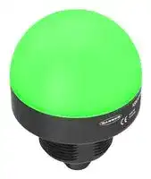


K50PSLKQ.
PROGRAMMABLE INDICATOR, RGB, 30VDC
- Manufacturer: BANNER ENGINEERING
- Product type: Visual Signal Indicator Units
- Module Lens Colour:Blue, Green, Red; Supply Voltage VAC:-; Supply Voltage VDC:30V; Visual Signal Type:Flashing; Lens Diameter:1.97"; Product Range:K50 Pro Series; I 46AM1377
- SVHC: No SVHC (15-Jan-2018)
- Power Rating: -
- Lens Diameter: 1.97"
- Product Range: K50 Pro Series
- External Height: 2.64"
- IP / NEMA Rating: IP66, IP67, IP69K
- Module Lens Colour: Blue, Green, Red
- Supply Voltage VAC: -
- Supply Voltage VDC: 30V
- Visual Signal Type: Flashing
- Operating Temperature Max: 50°C
- Operating Temperature Min: -40°C
| Delivery and price | |
|---|---|
| Units per pack | 1 |
| Price | 92.25 € |
| Current stock | 10+ |
| Lead time | 30 days |
**==> picture [148 x 792] intentionally omitted <==**

## K50 Pro Indicator Product Manual

Original Instructions p/n: 240395 Rev. C 30-May-25

© Banner Engineering Corp. All rights reserved. www.bannerengineering.com

K50 Pro Indicator Product Manual

## Contents

**Chapter 1 Features.................................................................................................................. 3** Models ........................................................................................................................................................................................................... 3 **Chapter 2 Wiring...................................................................................................................... 4 Chapter 3 Pro Editor ............................................................................................................... 5** Full Preview Connection (Required).............................................................................................................................................................. 5 K50 Pro Editor Program Options................................................................................................................................................................... 5 Discrete Control ...................................................................................................................................................................................... 6 Pulse Control .......................................................................................................................................................................................... 8 **Chapter 4 Specifications ...................................................................................................... 10** FCC Part 15 Class B for Unintentional Radiators.........................................................................................................................................11 Industry Canada ICES-003(B)......................................................................................................................................................................11 Dimensions.................................................................................................................................................................................................. 12 **Chapter 5 Accessories.......................................................................................................... 13** Pro Editor Hardware.................................................................................................................................................................................... 13 Cordsets ...................................................................................................................................................................................................... 14 Brackets ...................................................................................................................................................................................................... 14 Wash-Down Cover....................................................................................................................................................................................... 16 Elevated Mount System............................................................................................................................................................................... 16 **Chapter 6 Product Support and Maintenance .................................................................... 17** Clean with Mild Detergent and Warm Water ............................................................................................................................................... 17 Repairs ........................................................................................................................................................................................................ 17 Contact Us................................................................................................................................................................................................... 17 Banner Engineering Corp Limited Warranty................................................................................................................................................ 17

© Banner Engineering Corp. All rights reserved. www.bannerengineering.com

K50 Pro Indicator Product Manual

## Chapter Contents

Models.................................................................................................................................................................................................................. 3

## Chapter 1 Features

## 50 mm Programmable Multicolor RGB Indicator

- Bright, uniform indicator light

- Seven default colors in one device (Green, Red, Yellow, Blue, White, Cyan, Magenta)

- Programmable using Banner's Pro Editor software and Pro Converter Cable

- 30 mm threaded polycarbonate base

- Translucent polycarbonate dome

- Rugged IP66, IP67, IP69K per ISO 20653 and UL Type 4X and UL Type 13 design

- Bimodal inputs (PNP/NPN), depending on source wiring

## Models

**==> picture [440 x 46] intentionally omitted <==**

**----- Start of picture text -----**<br>
Family Style Color and Input Connector [(1)]<br>K50 PSL RGB7 Q<br>PSL = Pro Indicator RGB7 = RGB Multicolor (7 colors) Q = Integral 5-pin M12 male quick-disconnect connector<br>**----- End of picture text -----**<br>


> (1) Models with a quick-disconnect connector require a mating cordset.

© Banner Engineering Corp. All rights reserved. www.bannerengineering.com

page 3 of 18

30-May-25

K50 Pro Indicator Product Manual

## Chapter Contents

## Chapter 2

## Wiring

## 5-pin/Wire Models

**==> picture [500 x 130] intentionally omitted <==**

**----- Start of picture text -----**<br>
PNP Input NPN Input Pinout<br>bu (3) bu (3)<br>bk (4) 10–30 V DC bk (4) 10–30 V DC 1<br>1 1<br>2<br>bn (1) bn (1)<br>2 2 4<br>3 wh (2) 3 wh (2) 3 5<br>gy (5) gy (5) The gray wire (5) is the flash input.<br>F F<br>**----- End of picture text -----**<br>


## Default Color Definition

**==> picture [500 x 62] intentionally omitted <==**

**----- Start of picture text -----**<br>
Red Yellow Green Cyan Blue Magenta White<br>Input 1 X X X X<br>Input 2 X X X X<br>Input 3 X X X X<br>**----- End of picture text -----**<br>


An "X" denotes an active input. For example, when Input 1 and Input 3 are active, the indicator is magenta.

© Banner Engineering Corp. All rights reserved. www.bannerengineering.com

page 4 of 18

30-May-25

K50 Pro Indicator Product Manual

## Chapter Contents

Full Preview Connection (Required)..................................................................................................................................................................... 5 K50 Pro Editor Program Options.......................................................................................................................................................................... 5 Chapter 3 Pro Editor

**==> picture [112 x 68] intentionally omitted <==**

Use Banner's Pro Editor software and Pro Converter Cable to create custom configurations by selecting different colors, flash patterns, and animations. For more information visit www.bannerengineering.com/proeditor.

## Full Preview Connection (Required)

The full preview connection must be used for the K50 Pro Indicator.

**==> picture [500 x 219] intentionally omitted <==**

**----- Start of picture text -----**<br>
A = Pro Converter Cable (MQDC-506-USB)<br>B = Splitter (CSB-M1251FM1251M)<br>C = PC running Pro Editor software<br>D = Any Banner Pro Series-enabled device (K50 shown)<br>E<br>E = Power Supply (PSW-24-1, PSW-24-2, or PSD-24-4)<br>F = 8-Pin to 5-Pin Double-Ended Cordset (MQDC-801-5M-PRO),<br>required for 8-Pin models<br>A<br>C<br>D<br>B<br>F<br>**----- End of picture text -----**<br>


## K50 Pro Editor Program Options

When the K50 Pro device is connected to Pro Editor, the software displays two application tiles for Discrete Control and Pulse Control:

© Banner Engineering Corp. All rights reserved. www.bannerengineering.com

page 5 of 18

30-May-25

K50 Pro Indicator Product Manual

Pro Editor

## Discrete Control

Selecting the Discrete Control tile displays three I/O State tiles:

- Basic

- Advanced

- I/O Block

Discrete Control also contains the Pro ID function, accessed through one of the three I/O State tiles.

## Basic I/O State

Basic four-state control. Configurations made in Basic I/O State assign one wire to one state, with the following override control:

- Pin 1 (Brown) overrides Pin 4 (Black)

- Pin 2 (White) overrides Pins 1 and 4 (Brown and Black)

- Pin 5 (Gray) overrides Pins 1, 2, and 4 (Brown, White, and Black)

page 6 of 18

© Banner Engineering Corp. All rights reserved. www.bannerengineering.com

30-May-25

K50 Pro Indicator Product Manual

Pro Editor

## Advanced I/O State

Advanced, default I/O state, with 15 state options for maximum configuration ability. Configurations made in Advanced I/O State assign binary wiring combinations of all valid inputs to each state.

## I/O Block I/O State

Three-state control for use with I/O block. Configurations made in I/O Block assign states to the black, white, and combination of black and white wires for use with I/O blocks, for which power (brown) and common (blue) are always on for five-pin connections.

© Banner Engineering Corp. All rights reserved. www.bannerengineering.com

page 7 of 18

30-May-25

K50 Pro Indicator Product Manual

Pro Editor

## Pro ID

The Pro ID function allows the user to enter a known K50 model to configure a K50 Pro device automatically. The user must be in one of the three Discrete Control > I/O State tiles to access this menu.

1.

   - In the top menu, navigate to Pro ID › Enter Pro ID .

2. Enter the model number of the known K50 model that you want to replicate. Do not include the input or connection type from the model number.

   - For example: Model number K50LGYRPQ should be entered as K50LGYR.

3. Click Save to configure.

**==> picture [144 x 41] intentionally omitted <==**

**----- Start of picture text -----**<br>
1<br>» C)<br>2 3<br>=e Sie ae OT =><br>**----- End of picture text -----**<br>


The configurations from the K50 model are applied to the settings and are highlighted in yellow (see image below).

4. Click Write Device Settings to write the configuration to the device.

**==> picture [71 x 19] intentionally omitted <==**

**----- Start of picture text -----**<br>
4<br>Write Device Settings C)<br>**----- End of picture text -----**<br>


## Pulse Control

Selecting the Pulse Control tile displays up to sixteen states that correspond to input frequencies on the white wire. The number of states (1) and input characteristics (2) are user-defined. Ranges are calculated (3).

page 8 of 18

© Banner Engineering Corp. All rights reserved. www.bannerengineering.com

30-May-25

K50 Pro Indicator Product Manual

Pro Editor

**==> picture [324 x 40] intentionally omitted <==**

**----- Start of picture text -----**<br>
||||||
|---|---|---|---|---|
|1|2|
|CO|Applicay’sys|->|Pulse|Control|
|0|3|

**----- End of picture text -----**<br>


© Banner Engineering Corp. All rights reserved. www.bannerengineering.com

page 9 of 18

30-May-25

K50 Pro Indicator Product Manual

## Chapter Contents

FCC Part 15 Class B for Unintentional Radiators ...............................................................................................................................................11 Industry Canada ICES-003(B).............................................................................................................................................................................11 Dimensions......................................................................................................................................................................................................... 12

## Chapter 4

## Specifications

Supply Voltage and Current 10 V DC to 30 V DC

- 220 mA at 10 V DC (exclusive of load)

- • 190 mA at 12 V DC (exclusive of load) • 115 mA at 24 V DC (exclusive of load) • 100 mA at 30 V DC (exclusive of load)

## Supply Protection Circuitry

Protected against reverse polarity and transient voltages

Leakage Current Immunity 400 µA

Input Response Time

250 milliseconds maximum

## Flash

Default 1.5 Hz flash rate using flash input wire

## Vibration and Mechanical Shock

Meets IEC 60068-2-6 requirements (Vibration: 10 Hz to 55 Hz, 1.0 mm amplitude, 5 minutes sweep, 30 minutes dwell) Meets IEC 60068-2-27 requirements (Shock: 30G 11 ms duration, half sine wave)

Operating Conditions

–40 °C to +50 °C (–40 °F to +122 °F)

90% at +50 °C maximum relative humidity (non-condensing)

Storage Temperature: –40 °C to +70 °C (–40 °F to +158 °F)

Environmental Rating IP66, IP67, IP69K per ISO 20653

## Connections

Integral 5-pin M12 male quick-disconnect connector

## Mounting

M30 by 1.5 threaded base, maximum torque 4.5 N·m (40 inch-lbf) Mounting nut included

## Construction

Base and Dome: Polycarbonate Mounting Nut: Polybutylene terephthalate (PBT) Required Overcurrent Protection

WARNING: Electrical connections must be made by qualified personnel in accordance with local and national electrical codes and regulations.

Overcurrent protection is required to be provided by end product application per the supplied table.

Overcurrent protection may be provided with external fusing or via Current Limiting, Class 2 Power Supply. Supply wiring leads < 24 AWG shall not be spliced. For additional product support, go to www.bannerengineering.com.

**==> picture [208 x 68] intentionally omitted <==**

**----- Start of picture text -----**<br>
Supply  Supply<br>Required Overcurrent  Required Overcurrent<br>Wiring  Wiring<br>Protection (A) Protection (A)<br>(AWG) (AWG)<br>20 5.0 26 1.0<br>22 3.0 28 0.8<br>24 1.0 30 0.5<br>**----- End of picture text -----**<br>


Certifications

Banner Engineering BV Park Lane, Culliganlaan 2F bus 3 1831 Diegem, BELGIUM

© Banner Engineering Corp. All rights reserved. www.bannerengineering.com

page 10 of 18

30-May-25

Specifications

K50 Pro Indicator Product Manual

## Default Indicator Characteristics

**==> picture [483 x 149] intentionally omitted <==**

**----- Start of picture text -----**<br>
Color Coordinates [(2)]<br>Dominant Wavelength (nm) or Color Temperature  Lumen Output Per Segment<br>Color<br>(CCT) X Y (Typical at 25 °C)<br>Green 522 0.154 0.7 25.1<br>Red 620 0.689 0.309 13.9<br>Yellow 576 0.477 0.493 38.1<br>Blue 466 0.14 0.054 4<br>White 5700K 0.328 0.337 38.8<br>Cyan 493 0.17 0.34 27.9<br>Magenta - 0.379 0.172 16.8<br>**----- End of picture text -----**<br>


## FCC Part 15 Class B for Unintentional Radiators

(Part 15.105(b)) This equipment has been tested and found to comply with the limits for a Class B digital device, pursuant to part 15 of the FCC Rules. These limits are designed to provide reasonable protection against harmful interference in a residential installation. This equipment generates, uses, and can radiate radio frequency energy and, if not installed and used in accordance with the instructions, may cause harmful interference to radio communications. However, there is no guarantee that interference will not occur in a particular installation. If this equipment does cause harmful interference to radio or television reception, which can be determined by turning the equipment off and on, the user is encouraged to try to correct the interference by one or more of the following measures:

- Reorient or relocate the receiving antenna.

- Increase the separation between the equipment and receiver.

- Connect the equipment into an outlet on a circuit different from that to which the receiver is connected.

- Consult the dealer or an experienced radio/TV technician for help.

(Part 15.21) Any changes or modifications not expressly approved by the party responsible for compliance could void the user’s authority to operate this equipment.

## Industry Canada ICES-003(B)

This device complies with CAN ICES-3 (B)/NMB-3(B). Operation is subject to the following two conditions: 1) This device may not cause harmful interference; and 2) This device must accept any interference received, including interference that may cause undesired operation.

Cet appareil est conforme à la norme NMB-3(B). Le fonctionnement est soumis aux deux conditions suivantes : (1) ce dispositif ne peut pas occasionner d'interférences, et (2) il doit tolérer toute interférence, y compris celles susceptibles de provoquer un fonctionnement non souhaité du dispositif.

> (2) Refer to CIE 1931 chromaticity diagram or color chart to show equivalent color with indicated color coordinates. Actual coordinates may differ by 10%.

© Banner Engineering Corp. All rights reserved. www.bannerengineering.com

page 11 of 18

30-May-25

Specifications

K50 Pro Indicator Product Manual

## Dimensions

All measurements are listed in millimeters [inches], unless noted otherwise. The measurements provided are subject to change.

**==> picture [188 x 124] intentionally omitted <==**

**----- Start of picture text -----**<br>
50.0 mm<br>(1.97")<br>M30 x 1.5<br>(mounting nut<br>included)<br>Max. Torque 4.5 Nm<br>(40 in-lbf)<br>**----- End of picture text -----**<br>


**==> picture [46 x 107] intentionally omitted <==**

page 12 of 18

© Banner Engineering Corp. All rights reserved. www.bannerengineering.com

30-May-25

K50 Pro Indicator Product Manual

## Chapter Contents

Pro Editor Hardware........................................................................................................................................................................................... 13 Cordsets ............................................................................................................................................................................................................. 14 Brackets ............................................................................................................................................................................................................ 14 Wash-Down Cover ............................................................................................................................................................................................. 16 Elevated Mount System ..................................................................................................................................................................................... 16

## Chapter 5 Accessories

## Pro Editor Hardware

## MQDC-506-USB

- Pro Converter Cable

- 1.83 m (6 ft) length 5-pin M12 quick disconnect to Device and USB to PC

- • Required for connection to the configuration software

**==> picture [91 x 37] intentionally omitted <==**

## CSB-M1251FM1251M

- 5-pin parallel Y splitter (Male-Male-Female)

- • For full Pro Editor preview capability • Requires external power supply, sold separately

## PSW-24-1

- 24 V DC, 1 A power supply

- • 2 m (6.5 ft) PVC cable with M12 quick disconnect • Provides external power with splitter cable, sold separately

## PSW-24-2

- 24 V DC, 2 A power supply

- 3.5 m (11.5 ft) PVC cable with M12 quick disconnect

- • Provides external power with splitter cable, sold separately

© Banner Engineering Corp. All rights reserved. www.bannerengineering.com

page 13 of 18

30-May-25

K50 Pro Indicator Product Manual

Accessories

## Cordsets

All measurements are listed in millimeters [inches], unless noted otherwise. The measurements provided are subject to change.

**==> picture [500 x 327] intentionally omitted <==**

**----- Start of picture text -----**<br>
5-pin Double-Ended M12 Female to M12 Male Cordsets<br>Model Length Dimensions (mm) Pinouts<br>BC-M12F5-M12M5-22-1 1 m (3.28 ft) Female<br>2<br>BC-M12F5-M12M5-22-2 2 m (6.56 ft) 40 Typ.[1.58"] 1<br>BC-M12F5-M12M5-22-5 5 m (16.4 ft) 3<br>BC-M12F5-M12M5-22-8 8 m (26.25 ft) ø 14.5 [0.57"]M12 x 1 4 5 1 = Brown 2 = White<br>3 = Blue<br>BC-M12F5-M12M5-22-10 10 m (30.81 ft) 44 Typ.[1.73"] Male 4 = Black<br>5 = Gray<br>1<br>M12 x 1 2<br>BC-M12F5-M12M5-22-15 15 m (49.2 ft) ø 14.5 [0.57"] 4<br>3 5<br>5-pin Double-Ended M12 Female Right-Angle to M12 Male Right-Angle Cordsets<br>Model Length Dimensions (mm) Pinouts<br>BC-M12F5A-M12M5A-22-1 1 m (3.28 ft) Female<br>2<br>BC-M12F5A-M12M5A-22-2 2 m (6.56 ft) 32 Typ. 1<br>[1.26"]<br>BC-M12F5A-M12M5A-22-5 5 m (16.4 ft) 3<br>BC-M12F5A-M12M5A-22-8 8 m (26.25 ft) 30 Typ.[1.18"] 4 5 1 = Brown 2 = White<br>3 = Blue<br>BC-M12F5A-M12M5A-22-10 10 m (30.81 ft) M12 x 1 Male 4 = Black<br>ø 14.5 [0.57"]<br>31 Typ. 5 = Gray<br>1<br>2<br>BC-M12F5A-M12M5A-22-15 15 m (49.2 ft) 32 Typ. 4<br>3 5<br>**----- End of picture text -----**<br>


## Brackets

**==> picture [433 x 88] intentionally omitted <==**

**----- Start of picture text -----**<br>
45<br>• Right-angle bracket with curved slot for versatile orientation<br>• Clearance for M6 (¼ in) hardware C<br>61<br>• Mounting hole for 30 mm sensor<br>• 12-gauge stainless steel B<br>A<br>Hole center spacing:  A to B=40 69<br>Hole size:  A=ø 6.3, B= 27.1 × 6.3, C=ø 30.5<br>**----- End of picture text -----**<br>


## SMB30A

## SMB30FVK

- V-clamp, flat bracket and fasteners for mounting to pipe or extensions

- Clamp accommodates 28 mm dia. tubing or 1 in. square extrusions

- • 30 mm hole for mounting sensors

**==> picture [61 x 23] intentionally omitted <==**

**----- Start of picture text -----**<br>
46<br>118<br>A<br>**----- End of picture text -----**<br>


Hole size: A= ø 31

page 14 of 18

© Banner Engineering Corp. All rights reserved. www.bannerengineering.com

30-May-25

K50 Pro Indicator Product Manual

Accessories

## SMB30RAVK

- V-clamp, right-angle bracket and fasteners for mounting sensors to pipe or extrusion

- Clamp accommodates 28 mm dia. tubing or 1 in. square extrusions

- • 30 mm hole for mounting sensors

Hole size: A = ø 30.5

**==> picture [76 x 55] intentionally omitted <==**

**----- Start of picture text -----**<br>
A<br>46<br>57 90<br>**----- End of picture text -----**<br>


**==> picture [414 x 88] intentionally omitted <==**

**----- Start of picture text -----**<br>
45<br>• Flat SMBAMS series bracket<br>C<br>• 30 mm hole for mounting sensors<br>• Articulation slots for 90°+ rotation A<br>93<br>• 12-gauge 300 series stainless steel B<br>Hole center spacing:  A=26.0, A to B=13.0<br>A=26.8 × 7.0, B=ø 6.5, C=ø 31.0<br>**----- End of picture text -----**<br>


## SMBAMS30P

Hole center spacing: A=26.0, A to B=13.0 Hole size: A=26.8 × 7.0, B=ø 6.5, C=ø 31.0

## SMBAMS30RA

- Right-angle SMBAMS series bracket

- • 30 mm hole for mounting sensors • Articulation slots for 90°+ rotation

- 12-gauge (2.6 mm) cold-rolled steel

Hole center spacing: A=26.0, A to B=13.0 Hole size: A=26.8 × 7.0, B=ø 6.5, C=ø 31.0

**==> picture [54 x 56] intentionally omitted <==**

**----- Start of picture text -----**<br>
45<br>C<br>53 A<br>B<br>48<br>**----- End of picture text -----**<br>


**==> picture [429 x 86] intentionally omitted <==**

**----- Start of picture text -----**<br>
70 57<br>• 12-gauge stainless steel bracket with curved mounting slots for versatile<br>orientation<br>• Clearance for M6 (¼ in) hardware 57 C<br>• Mounting hole for 30 mm sensor B<br>Hole center spacing:  A = 51, A to B = 25.4<br> A = 42.6 × 7, B = ø 6.4, C = ø 30.1 A<br>**----- End of picture text -----**<br>


## SMB30MM

Hole center spacing: A = 51, A to B = 25.4 Hole size: A = 42.6 × 7, B = ø 6.4, C = ø 30.1

**==> picture [432 x 191] intentionally omitted <==**

**----- Start of picture text -----**<br>
67<br>• Swivel bracket with 30 mm mounting hole for sensor B<br>• Black reinforced thermoplastic polyester 58<br>• Stainless steel mounting and swivel locking hardware included<br>Hole center spacing:  A=ø 50.8<br>A=ø 7.0, B=ø 30.0 29 A<br>• Swivel bracket with tilt and pan movement for precise adjustment 83.2<br>• Mounting hole for 30 mm sensor<br>• 12-gauge 304 stainless steel<br>• Easy sensor mounting to extrude rail T-slot 36.3 B 68.9<br>• Metric- and inch-size bolt available<br>A<br> SMB30FA, A= 3/8 - 16 × 2 in; SMB30FAM10, A= M10 - 1.5 × 50<br> B= ø 30.1<br>**----- End of picture text -----**<br>


## SMB30SC

Hole center spacing: A=ø 50.8 Hole size: A=ø 7.0, B=ø 30.0

## SMB30FA

- Bolt thread: SMB30FA, A= 3/8 - 16 × 2 in; SMB30FAM10, A= M10 - 1.5 × 50 Hole size: B= ø 30.1

© Banner Engineering Corp. All rights reserved. www.bannerengineering.com

page 15 of 18

30-May-25

K50 Pro Indicator Product Manual

Accessories

- 55 35

- • Direct mounting of stand-off pipe, with common bracket type 38.25 • Zinc-plated steel • 1/2-14 NPSM nut • Mounting distance from the wall to the center of the 1/2-14 NPSM nut is 35 mm 57

- Hole center spacing: 20.0 2X Ø9

## LMBE12RA35

## LMBE12RA45

- Direct mounting of stand-off pipe, with common bracket type

- • Zinc-plated steel • 1/2-14 NPSM nut • Mounting distance from the wall to the center of the 1/2-14 NPSM nut is 45 mm

Hole center spacing: 35.0

**==> picture [65 x 81] intentionally omitted <==**

**----- Start of picture text -----**<br>
65<br>45<br>38.25<br>81<br>2X Ø11<br>**----- End of picture text -----**<br>


All measurements are listed in millimeters [inches], unless noted otherwise. The measurements provided are subject to change.

## Wash-Down Cover

## WC-K50 Washdown Cover

- FDA-grade silicone

- • Fits K50 indicators • IP67 and IP69K rated

**==> picture [59 x 32] intentionally omitted <==**

## Elevated Mount System

Model Description Components • Streamlined black acetal stand-off pipe adapter/cover • Connects between 30 mm light base and ½ in. NPSM/ SA-M30E12P - Black Acetal DN15 pipe • Mounting hardware included Black Anodized Aluminum Clear Anodized Aluminum SOP-E12-150A SOP-E12-150AC 150 mm (6 in) long 150 mm (6 in) long • Elevated-use stand-off pipe (½ in. NPSM/DN15) • Polished 304 stainless steel, black anodized aluminum, or SOP-E12-300A SOP-E12-300AC clear anodized aluminum surface 300 mm (12 in) long 300 mm (12 in) long • ½ in. NPT thread at both ends: one end screws into the internal threads of the light's base, and one end screws into SOP-E12-600A SOP-E12-600AC the mounting base adapter/cover • Compatible with most industrial environments 600 mm (24 in) long 600 mm (24 in) long SOP-E12-900A SOP-E12-900AC 900 mm (36 in) long 900 mm (36 in) long

page 16 of 18

© Banner Engineering Corp. All rights reserved. www.bannerengineering.com

30-May-25

K50 Pro Indicator Product Manual

## Chapter Contents

Clean with Mild Detergent and Warm Water ...................................................................................................................................................... 17 Repairs ............................................................................................................................................................................................................... 17 Contact Us.......................................................................................................................................................................................................... 17 Banner Engineering Corp Limited Warranty....................................................................................................................................................... 17

## Chapter 6 Product Support and Maintenance

## Clean with Mild Detergent and Warm Water

Wipe down the device with a soft cloth dampened with a mild detergent and warm water solution. Do not use any other chemicals for cleaning.

## Repairs

Contact Banner Engineering for troubleshooting of this device. Do not attempt any repairs to this Banner device; it contains no field-replaceable parts or components. If the device, device part, or device component is determined to be defective by a Banner Applications Engineer, they will advise you of Banner's RMA (Return Merchandise Authorization) procedure.

IMPORTANT: If instructed to return the device, pack it with care. Damage that occurs in return shipping is not covered by warranty.

## Contact Us

Banner Engineering Corp. headquarters is located at: 9714 Tenth Avenue North | Plymouth, MN 55441, USA | Phone: + 1 888 373 6767

For worldwide locations and local representatives, visit www.bannerengineering.com.

## Banner Engineering Corp Limited Warranty

Banner Engineering Corp. warrants its products to be free from defects in material and workmanship for one year following the date of shipment. Banner Engineering Corp. will repair or replace, free of charge, any product of its manufacture which, at the time it is returned to the factory, is found to have been defective during the warranty period. This warranty does not cover damage or liability for misuse, abuse, or the improper application or installation of the Banner product.

THIS LIMITED WARRANTY IS EXCLUSIVE AND IN LIEU OF ALL OTHER WARRANTIES WHETHER EXPRESS OR IMPLIED (INCLUDING, WITHOUT LIMITATION, ANY WARRANTY OF MERCHANTABILITY OR FITNESS FOR A PARTICULAR PURPOSE), AND WHETHER ARISING UNDER COURSE OF PERFORMANCE, COURSE OF DEALING OR TRADE USAGE.

This Warranty is exclusive and limited to repair or, at the discretion of Banner Engineering Corp., replacement. IN NO EVENT SHALL BANNER ENGINEERING CORP. BE LIABLE TO BUYER OR ANY OTHER PERSON OR ENTITY FOR ANY EXTRA COSTS, EXPENSES, LOSSES, LOSS OF PROFITS, OR ANY INCIDENTAL, CONSEQUENTIAL OR SPECIAL DAMAGES RESULTING FROM ANY PRODUCT DEFECT OR FROM THE USE OR INABILITY TO USE THE PRODUCT, WHETHER ARISING IN CONTRACT OR WARRANTY, STATUTE, TORT, STRICT LIABILITY, NEGLIGENCE, OR OTHERWISE.

Banner Engineering Corp. reserves the right to change, modify or improve the design of the product without assuming any obligations or liabilities relating to any product previously manufactured by Banner Engineering Corp. Any misuse, abuse, or improper application or installation of this product or use of the product for personal protection applications when the product is identified as not intended for such purposes will void the product warranty. Any modifications to this product without prior express approval by Banner Engineering Corp will void the product warranties. All specifications published in this document are subject to change; Banner reserves the right to modify product specifications or update documentation at any time. Specifications and product information in English supersede that which is provided in any other language. For the most recent version of any documentation, refer to: www.bannerengineering.com.

For patent information, see www.bannerengineering.com/patents.

© Banner Engineering Corp. All rights reserved. www.bannerengineering.com

page 17 of 18

30-May-25

## LinkedIn

## X (formerly Twitter)

## Facebook

© 2025. All rights reserved. www.bannerengineering.com
Updated at April 23, 2026
Founded in 1966, Banner Engineering is a globally recognized leader in the design and manufacture of industrial automation products. The company is renowned for developing innovative, high-quality solutions that improve operational efficiency, safeguard personnel, and optimize manufacturing processes across a diverse range of industries. Our extensive selection of Banner Engineering components prominently features their industry-leading sensing technologies. We offer a comprehensive array of precision light sensors engineered for accurate detection and measurement in demanding environments. Complementing this core sensing portfolio is a robust offering of automation signaling devices, including visual signal indicator units and essential accessories, which provide clear and immediate communication of machine status. Beyond primary sensing and indication solutions, our range encompasses critical components for broader process control and machine safety. This includes advanced process controllers, reliable pressure sensors and transducers, and dependable safety relays. Supported by a variety of purpose-built sensor accessories and fiber optic lead assemblies, Banner Engineering delivers the durable, high-performance technologies required to build and maintain sophisticated automated systems.
About Novapart
Novapart is a B2B electronic component broker specialising in stock shortages and cost reduction. We source hard-to-find parts and identify compliant alternatives across a catalogue of 540,000+ components from 500+ manufacturers.
Learn more →Stock Shortage Specialist
When a component is unavailable, discontinued or has an unacceptable lead time, we tap into our network of vetted European and Asian distributors to source what you need — without compromising on quality or traceability.
Request a quote →Compliant Alternatives
We identify pin-to-pin, electrically equivalent substitutes that meet the same certifications (RoHS, AEC-Q100, REACH) as your original specification — validated against datasheets, not just part numbers. Often at a lower cost.
BOM Analysis service →