
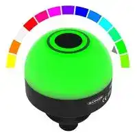


K50PSAF1000GRY3Q.
INDICATOR, GREEN, RED, YELLOW, 30VDC
- Manufacturer: BANNER ENGINEERING
- Product type: Visual Signal Indicator Units
- Module Lens Colour:Green, Red, Yellow; Supply Voltage VAC:-; Supply Voltage VDC:30V; Visual Signal Type:Flashing; Lens Diameter:50mm; Product Range:K50 Pro Series 27AM5620
- SVHC: No SVHC (15-Jan-2018)
- Power Rating: -
- Lens Diameter: 50mm
- Product Range: K50 Pro Series
- External Height: 63.1mm
- IP / NEMA Rating: IP66, IP67, IP69K
- Module Lens Colour: Green, Red, Yellow
- Supply Voltage VAC: -
- Supply Voltage VDC: 30V
- Visual Signal Type: Flashing
- Operating Temperature Max: 50°C
- Operating Temperature Min: -20°C
| Delivery and price | |
|---|---|
| Units per pack | 10 |
| Price | 109.32 € |
| Current stock | 10+ |
| Lead time | 30 days |
**==> picture [148 x 792] intentionally omitted <==**

K50 Pro Optical Sensor Product Manual

Original Instructions p/n: 240397 Rev. C 05-Jun-25

© Banner Engineering Corp. All rights reserved. www.bannerengineering.com

K50 Pro Optical Sensor Product Manual

## Contents

**Chapter 1 Features.................................................................................................................. 3** Models ........................................................................................................................................................................................................... 3 Overview........................................................................................................................................................................................................ 3 Class 1 Laser Description and Safety Information ........................................................................................................................................ 4 **Chapter 2 Wiring...................................................................................................................... 6 Chapter 3 Configuring a Sensor ............................................................................................ 7** Remote Input ................................................................................................................................................................................................. 7 Remote Teach ........................................................................................................................................................................................ 7 Teach Modes and Operation................................................................................................................................................................... 8 Object Mode (default) ............................................................................................................................................................................. 8 Background Mode................................................................................................................................................................................... 8 Window Mode ......................................................................................................................................................................................... 9 Reset the Sensor to Factory Defaults............................................................................................................................................................ 9 Reset Using the Banner Pro Editor Software ................................................................................................................................................ 9 Reset Using the Remote Input ...................................................................................................................................................................... 9 Factory Default Settings via Remote Teach Mode.................................................................................................................................. 9 **Chapter 4 Alternate Modes through Pro Editor...................................................................11** Detection ......................................................................................................................................................................................................11 Device Logic Mode ................................................................................................................................................................................11 Distance....................................................................................................................................................................................................... 13 Coarse Distance .......................................................................................................................................................................................... 13 Advanced Settings....................................................................................................................................................................................... 14 **Chapter 5 Specifications ...................................................................................................... 15** FCC Part 15 Class B for Unintentional Radiators........................................................................................................................................ 16 Industry Canada ICES-003(B)..................................................................................................................................................................... 16 Dimensions.................................................................................................................................................................................................. 17 Beam Pattern............................................................................................................................................................................................... 17 **Chapter 6 Accessories.......................................................................................................... 18** Pro Editor Hardware.................................................................................................................................................................................... 18 Cordsets ...................................................................................................................................................................................................... 19 Brackets ...................................................................................................................................................................................................... 20 Elevated Mount System............................................................................................................................................................................... 22 **Chapter 7 Product Support and Maintenance .................................................................... 23** Clean with Mild Detergent and Warm Water ............................................................................................................................................... 23 Repairs ........................................................................................................................................................................................................ 23 Contact Us................................................................................................................................................................................................... 23 Banner Engineering Corp Limited Warranty................................................................................................................................................ 23

© Banner Engineering Corp. All rights reserved. www.bannerengineering.com

K50 Pro Optical Sensor Product Manual

Chapter Contents

Models.................................................................................................................................................................................................................. 3 Overview .............................................................................................................................................................................................................. 3 Class 1 Laser Description and Safety Information ............................................................................................................................................... 4

Chapter 1

## Features

## 50 mm Programmable Multicolor RGB Optical Sensor and Indicator

      - Programmable using Banner's Pro Editor software and Pro Converter Cable

      - • Three default colors in one device (Green, Red, Yellow) • Devices are completely self-contained—no controller needed • Teachable modes with color feedback for ease of use • Touchless activation removes the need for physical force to activate • Rugged IP66, IP67, IP69K per ISO 20653 and UL Type 4X and UL Type 13 design • Resistant to ambient light, EMI, and RFI interference • Sensing and indication in one device • Bright, uniform indicator light • Translucent polycarbonate dome • Bimodal inputs and output (PNP/NPN), depending on source wiring

- WARNING: • Do not use this device for personnel protection • Using this device for personnel protection could result in serious injury or death.

   - This device does not include the self-checking redundant circuitry necessary to allow its use in personnel safety applications. A device failure or malfunction can cause either an energized (on) or de-energized (off) output condition.

## Models

**==> picture [463 x 54] intentionally omitted <==**

**----- Start of picture text -----**<br>
Family Style Color and Input Connector [(1)]<br>K50 PSAF1000 GRY3 Q<br>PSAF1000 = 1000 mm  GRY3 = RGB Multicolor (3 colors, 5-pin) Q = Integral 5-pin or 8-pin M12 male<br>Adjustable Field Sensor quick-disconnect connector<br>RGB14 = RGB Multicolor (14 colors, 8-pin)<br>**----- End of picture text -----**<br>


## Overview

The K50 Pro Optical Sensor is an adjustable field optical sensor that can detect a wide variety of materials and objects.

Configure the sensor using software or remote input wires to sense objects up to a specific distance, ignoring objects beyond this distance (background suppression), or within a windowed range.

> (1) Models with a quick-disconnect connector require a mating cordset.

© Banner Engineering Corp. All rights reserved. www.bannerengineering.com

page 3 of 24

05-Jun-25

K50 Pro Optical Sensor Product Manual

Features

- Measurement **Detection Area**

- Reference Point Detection not Reliable detection of a stationary

- ooo possible and moving object **D0 D1 D2**

- Model D0 (mm) Switch Point D1 (mm) Switch Point D2 (mm)

- K50PSAF1000GRY3Q 0 20 1000

- Class 1 Laser Description and Safety Information Laser light. Do not stare into the beam. **CLASS 1 LASER PRODUCT**

- Complies with 21 CFR 1040.10 and 1040.11 except for deviations

- A pursuant to Laser Notice No. 56, dated May 8, 2019. - CAUTION: • Never stare directly into the sensor lens. • Laser light can damage your eyes.

- AN • Avoid placing any mirror-like object in the beam. Never use a mirror as a retroreflective target. CAUTION: • Return defective units to the manufacturer. • Use of controls or adjustments or performance of procedures other than those specified herein may result in hazardous radiation exposure.

- AN • Do not attempt to disassemble this sensor for repair. A defective unit must be returned to the manufacturer.

- CAUTION: • Ne regardez jamais directement la lentille du capteur. • La lumière laser peut endommager la vision.

- AN • Évitez de placer un objet réfléchissant (de type miroir) dans la trajectoire du faisceau. N'utilisez jamais de miroir comme cible rétro-réfléchissante.

- CAUTION: • Tout dispositif défectueux doit être renvoyé au fabricant. • L'utilisation de commandes, de réglages ou de procédures autres que celles décrites dans le présent document peut entraîner une exposition dangereuse aux radiations.

- AN • N'essayez pas de démonter ce capteur pour le réparer. Tout dispositif défectueux doit être renvoyé au fabricant.

## Class 1 Laser Description and Safety Information

Class 1 lasers are lasers that are safe under reasonably foreseeable conditions of operation, including the use of optical instruments for intrabeam viewing.

Complies with IEC 60825-1:2014 and EN 60825-1:2014+A11:2021.

page 4 of 24

© Banner Engineering Corp. All rights reserved. www.bannerengineering.com

05-Jun-25

K50 Pro Optical Sensor Product Manual

Features

## For safe laser use:

- Do not stare at the laser.

- Do not point the laser at a person’s eye.

- Mount open laser beam paths either above or below eye level, where practical.

- Terminate the beam emitted by the laser product at the end of its useful path.

© Banner Engineering Corp. All rights reserved. www.bannerengineering.com

page 5 of 24

05-Jun-25

K50 Pro Optical Sensor Product Manual

## Chapter Contents

## Chapter 2

## Wiring

GRY3 Wiring Diagrams

**==> picture [500 x 144] intentionally omitted <==**

**----- Start of picture text -----**<br>
NPN PNP Pinout<br>bn (1) – bn (1) +<br>1<br>bu (3) 10-30 V DC+ bu (3) 10-30 V DC– 2<br>bk (4) bk (4) 4<br>Load Load<br>3 5<br>1 wh (2) 1 wh (2) Pin 4 (Black) is Output 1.<br>Touch actuation toggles the<br>gy (5) gy (5) output.<br>2 2<br>**----- End of picture text -----**<br>


GRY3 Multicolor Color/Function Definition

**==> picture [500 x 46] intentionally omitted <==**

**----- Start of picture text -----**<br>
Green Yellow Red<br>Input 1 X X<br>Input 2 X X<br>**----- End of picture text -----**<br>


RGB14 Wiring Diagrams

**==> picture [500 x 192] intentionally omitted <==**

**----- Start of picture text -----**<br>
NPN PNP Pinout<br>bn (2) – bn (2) +<br>12-30 V DC 12-30 V DC<br>bu (7) + bu (7) –<br>wh (1) Load wh (1) Load<br>1<br>7<br> 1 gn (3)  1 gn (3)<br>2 6<br>rd (8) rd (8)<br> 2  2 3<br>5<br> 3 ye (4)  3 ye (4) 4 8<br>gy (5) gy (5)<br> 4  4<br>pk (6) pk (6)<br>Flash Input Flash Input<br>**----- End of picture text -----**<br>


RGB14 Multicolor Color/Function Definition

**==> picture [500 x 85] intentionally omitted <==**

**----- Start of picture text -----**<br>
Red Yellow Green Cyan Blue Magenta White Amber Rose GreenLime  Orange BlueSky  Violet Spring Green<br>Input 1 X X X X X X X<br>Input 2 X X X X X X X<br>Input 3 X X X X X X X<br>Input 4 X X X X X X X<br>**----- End of picture text -----**<br>


© Banner Engineering Corp. All rights reserved.

page 6 of 24

05-Jun-25

www.bannerengineering.com

K50 Pro Optical Sensor Product Manual

## Chapter Contents

Remote Input........................................................................................................................................................................................................ 7 Reset the Sensor to Factory Defaults .................................................................................................................................................................. 9 Reset Using the Banner Pro Editor Software....................................................................................................................................................... 9 Reset Using the Remote Input ............................................................................................................................................................................. 9

## Chapter 3 Configuring a Sensor

The K50 Pro Optical Sensor has three Teach modes. These modes are indicated with a Teach Status color.

The Signal Level color flashes in between the Teach Status color. The color of the Signal Level depends on the signal strength of the target:

Green: Best signal, accepts Teach Yellow: Acceptable signal, can accept Teach Red: Poor signal, rejects Teach

## Remote Input

Use the remote input to program the sensor remotely.

The remote input provides limited programming options and is Active High in PNP mode (V+ to brown wire), or Active Low in NPN mode (V+ to blue wire). For Active High, pulse the gray or yellow input wire to V+ (10 V DC to 30 V DC). For Active Low, pulse the gray or yellow input wire to ground (0 V DC).

The remote input wire is enabled by default. Pulse the remote input wire 7 times or use the Banner Pro Editor software to enable or disable the feature. When the remote input feature is enabled, pulse the remote input according to the diagram and the instructions provided in this manual. Remote teach can also be performed using the button on the Pro Converter Cable.

The length of the individual programming pulses is equal to the value T: 0.04 seconds ≤ T ≤ 0.8 seconds .

Exit remote programming modes by cycling power or by waiting for 30 seconds.

NOTE: If a factory reset is performed through the Banner Pro Editor Software, the remote input wire becomes enabled (factory default setting). If the sensor is returned to factory defaults by using the remote input wire, the input wire remains enabled and the rest of the settings are restored to factory defaults.

## Remote Teach

Use the following procedure to teach the Set Point.

1. Pulse the remote input:

   - 3x - Object Teach: The indicator alternates between a blue Teach Status color and the Signal Level color.

   - 4x - Background Teach: The indicator alternates between a magenta Teach Status color and the Signal Level color.

   - 5x - Window Teach: The indicator alternates between a cyan Teach Status color and the Signal Level color.

2. Present the Set Point.

3. Teach the Set Point.

**==> picture [470 x 102] intentionally omitted <==**

**----- Start of picture text -----**<br>
Action Result<br>Teach Accepted<br>The indicator stops flashing and the device returns to operation.<br>T Teach Not Accepted<br>Single pulse the remote input.<br>The Signal Level color turns red during the teach procedure, and<br>then the indicator stops flashing.<br>Retry teaching the set point.<br>**----- End of picture text -----**<br>


© Banner Engineering Corp. All rights reserved. www.bannerengineering.com

page 7 of 24

05-Jun-25

K50 Pro Optical Sensor Product Manual

Configuring a Sensor

**==> picture [335 x 293] intentionally omitted <==**

**----- Start of picture text -----**<br>
Remote Input Map<br>Remote<br>Input Gray/Yellow wire is remote teach input Pulse Timing (T)<br>0.04 seconds < T < 0.8 seconds<br>Timing between pulse less than 1 second<br>3x Object Mode Teach<br>1x Confirm Teach<br>4x Background Mode Teach<br>1x Confirm Teach<br>5x Window Mode Teach<br>1x Confirm Teach<br>7x Enable/Disable Remote Teach<br>1x Confirm Enable/Disable<br>9x Reset to Factory Defaults<br>1x Confirm Factory Reset<br>**----- End of picture text -----**<br>


## Teach Modes and Operation

## Object Mode (default)

Teach Status Color: Blue

The K50 Pro Optical Sensor is configured to Object Mode by default. Object Mode sets the total Detection Area from the sensor to the Set Point plus the Offset Value (50 mm default). Use Object Mode to trigger a change in state when an object is present between the sensor minimum (20 mm default) and the taught distance plus the offset.

Three-pulse the remote input to enable Object Mode. Successfully entering Object Mode causes the device to alternate between the Teach Status color (Blue) and the Signal Level color.

**==> picture [134 x 64] intentionally omitted <==**

**----- Start of picture text -----**<br>
+50 mm<br>(Offset Value)<br>Detection Area<br>Set Point Switch Point (D2)<br>**----- End of picture text -----**<br>


## Background Mode

Teach Status Color: Magenta

Background Mode sets the total Detection Area from the sensor to the Set Point minus the Offset Value (50 mm default). Use Background Mode when there is a constant background object present and a state change is desired when another object is in front of that background.

Four-pulse the remote input to enable Background Mode. Successfully entering Background Mode causes the device to alternate between the Teach Status color (Magenta) and the Signal Level color.

page 8 of 24

© Banner Engineering Corp. All rights reserved. www.bannerengineering.com

05-Jun-25

K50 Pro Optical Sensor Product Manual

Configuring a Sensor

**==> picture [126 x 69] intentionally omitted <==**

**----- Start of picture text -----**<br>
Detection Area<br>-50 mm<br>(Offset Value)<br>Switch Point (D2) Set Point<br>**----- End of picture text -----**<br>


## Window Mode

Teach Status Color: Cyan

Window Mode centers the total Detection Area at the Set Point plus and minus the Offset Value (50 mm default). Configuring a window near the minimum and maximum ranges shifts this window to ensure that it maintains this value. Use Window Mode when a change in state is desired within a specific narrow area, and not when outside this area.

Five-pulse the remote input to enable Window Mode. Successfully entering Window Mode causes the device to alternate between the Teach Status color (Cyan) and the Signal Level color.

**==> picture [135 x 86] intentionally omitted <==**

**----- Start of picture text -----**<br>
Detection Area<br>-50 mm +50 mm<br>(Offset Value) (Offset Value)<br>Switch Point (D1) Set Point Switch Point (D2)<br>**----- End of picture text -----**<br>


## Reset the Sensor to Factory Defaults

Reset the sensor to factory default settings using one of two methods.

NOTE: If a factory reset is performed through the Banner Pro Editor software, the remote input wire becomes disabled (factory default setting). If the sensor is returned to factory default settings by using the remote input wire, the input wire remains enabled and the rest of the settings are restored to factory defaults.

## Reset Using the Banner Pro Editor Software

Go to Sensor › Factory Reset . The sensor indicators flash once, the sensor is reset back to the factory default settings, and a confirmation message displays.

## Reset Using the Remote Input

Nine-pulse the remote input to reset the device to factory default settings. The device then flashes white on success.

Pulse the remote input once more to apply the factory defaults.

## Factory Default Settings via Remote Teach Mode

## Default Settings

**==> picture [500 x 101] intentionally omitted <==**

**----- Start of picture text -----**<br>
Setting Factory Default<br>Discrete Output and Remote Input Bimodal<br>Remote Input Wire Enabled<br>Offset 50 mm (2 in)<br>Operation Mode Object Mode<br>D1 20 mm (0.8 in)<br>Continued on page 10<br>**----- End of picture text -----**<br>


© Banner Engineering Corp. All rights reserved. www.bannerengineering.com

page 9 of 24

05-Jun-25

K50 Pro Optical Sensor Product Manual

Configuring a Sensor

**==> picture [500 x 83] intentionally omitted <==**

**----- Start of picture text -----**<br>
Continued from page 9<br>Setting Factory Default<br>D2 1000 mm (39.4 in)<br>NO/NC Normally open<br>On Delay 0 ms<br>Off Delay 0 ms<br>**----- End of picture text -----**<br>


page 10 of 24

© Banner Engineering Corp. All rights reserved. www.bannerengineering.com

05-Jun-25

K50 Pro Optical Sensor Product Manual

## Chapter Contents

Detection .............................................................................................................................................................................................................11 Distance ............................................................................................................................................................................................................. 13 Coarse Distance................................................................................................................................................................................................. 13 Advanced Settings ............................................................................................................................................................................................. 14

## Chapter 4 Alternate Modes through Pro Editor

Optical sensors have the following animations available to them:

**==> picture [494 x 176] intentionally omitted <==**

**----- Start of picture text -----**<br>
|||
|---|---|
|Animations|Description|
|Off|Device or segment is off|
|Steady|Color 1 is on at the defined intensity|
|Flash|Color 1 flashes at the defined speed, color intensity, and pattern (normal, strobe, three pulses, SOS, or random)|
|Two Color Flash|Color 1 and Color 2 flash alternately at the defined speed, color intensities, and pattern (normal, strobe, three pulses, SOS,|
|or random)|
|50/50|Color 1 displays on 50% and Color 2 displays on the other 50% statically at the defined color intensities|
|50/50 Rotate|Color 1 displays on 50% and Color 2 displays on the other 50% while rotating at the defined speed, color intensities,|
|rotational direction|
|Chase|Color 1 is displayed as a single spot against the background of Color 2 while rotating at the defined speed, color|
|intensities, rotational direction|
|Color 1 continuously increases and decreases intensity between 0% to 100% on each device or on every segment at the|
|Intensity Sweep|
|defined speed and color intensity|
|Demo|Demo sequence cycles through several sets of colors and configurations to highlight example applications|

**----- End of picture text -----**<br>


Set sensor parameters for the following applications:

- Detection

- Distance

- Coarse Distance

## Detection

Detect materials or objects using an adjustable field up to a specific distance, ignoring objects beyond this distance (background suppression), or within a windowed range.

DETECTION

## Device Logic Mode

After connecting a sensor and navigating to the Detection application, Device Logic Mode configuration displays.

By default, when a sensor is connected and the user navigates to the Detection application, Pro Editor opens Device Logic Mode configuration populated with the configuration written to the device. If no device logic mode is selected, use the Device Logic Mode drop-down to select a logic mode, then write the configuration to the device. Three Device Logic Modes are available:

- Four State Full Logic

- Three State Advanced Control

- Seven State Advanced Control

## Device Logic Mode – Four State Full Logic

When using Four State Full Logic, four device states are activated by one input wire and the sensor. The sensor also toggles the output(s).

© Banner Engineering Corp. All rights reserved. www.bannerengineering.com

page 11 of 24

05-Jun-25

K50 Pro Optical Sensor Product Manual

Alternate Modes through Pro Editor

Assuming power is on using the blue and brown wires:

State 1: Input Inactive, Touch Inactive State 2: Input Active, Touch Inactive State 3: Input Inactive, Touch Active State 4: Input Active, Touch Active

## Device Logic Mode – Three State Advanced Control

When using Three State Advanced Control, four device states are activated by two input wires. The sensor toggles the output(s) with no device state change.

## Device Logic Mode – Seven State Advanced Control

NOTE: Seven State Advanced Control is only available on 8-pin models.

When using Seven State Advanced Control, seven device states are activated by three input wires. An additional power state can be defined. The sensor toggles the output(s) with no device state change.

Voltage values shown in wiring diagrams vary depending on the connected device.

page 12 of 24

© Banner Engineering Corp. All rights reserved. www.bannerengineering.com

05-Jun-25

K50 Pro Optical Sensor Product Manual

Alternate Modes through Pro Editor

## Distance

Set the device to operate as a gauge, which allows the user to configure a background color and a fill color to display how far an object is within the Detection Area.

As an object moves along the sensing range, the proportion of fill color to background color changes in a clockwise (CW) or counter-clockwise (CCW) direction. The proportion of fill color increases as an object approaches the maximum range, and decreases as it moves towards the minimum.

**==> picture [24 x 4] intentionally omitted <==**

**----- Start of picture text -----**<br>
DISTANCE<br>**----- End of picture text -----**<br>


**==> picture [63 x 8] intentionally omitted <==**

**----- Start of picture text -----**<br>
Distance settings<br>**----- End of picture text -----**<br>


## Coarse Distance

Divide the Detection Area into custom zones to generate a unique animation when an object is present within that zone distance.

Configure up to six zones for animation and output state. The minimum zone distance is 50 mm.

**==> picture [45 x 5] intentionally omitted <==**

**----- Start of picture text -----**<br>
COARSE DISTANCE<br>**----- End of picture text -----**<br>


© Banner Engineering Corp. All rights reserved. www.bannerengineering.com

page 13 of 24

05-Jun-25

K50 Pro Optical Sensor Product Manual

Alternate Modes through Pro Editor

## Coarse distance settings

## Advanced Settings

When a sensor device is connected, the following Advanced Settings can be accessed by clicking on the AdvancedSettings menu.

## Optical AF Sensor Advanced Settings – Pro Editor

page 14 of 24

© Banner Engineering Corp. All rights reserved. www.bannerengineering.com

05-Jun-25

K50 Pro Optical Sensor Product Manual

## Chapter Contents

FCC Part 15 Class B for Unintentional Radiators .............................................................................................................................................. 16 Industry Canada ICES-003(B)............................................................................................................................................................................ 16 Dimensions......................................................................................................................................................................................................... 17 Beam Pattern ..................................................................................................................................................................................................... 17

## Chapter 5

## Specifications

Supply Voltage and Current 10 V DC to 30 V DC

- 220 mA at 10 V DC (exclusive of load)

- • 190 mA at 12 V DC (exclusive of load) • 115 mA at 24 V DC (exclusive of load) • 100 mA at 30 V DC (exclusive of load)

Supply Protection Circuitry

Protected against transient voltages and output short-circuit

Leakage Current Immunity 400 µA

Vibration and Mechanical Shock

Meets IEC 60068-2-6 requirements (Vibration: 10 Hz to 55 Hz, 1.0 mm amplitude, 5 minutes sweep, 30 minutes dwell) Meets IEC 60068-2-27 requirements (Shock: 30G 11 ms duration, half sine wave)

## Operating Conditions

- –20 °C to +50 °C (–4 °F to +122 °F)

90% at +50 °C maximum relative humidity (non-condensing)

Storage Temperature: –40 °C to +70 °C (–40 °F to +158 °F)

Environmental Rating

IP66, IP67, IP69K per ISO 20653

Connections

Integral 5-pin M12 male quick-disconnect connector or integral 8-pin M12 male quick-disconnect connector

Mounting M30 by 1.5 threaded base, maximum torque 4.5 N·m (40 inch-lbf)

Mounting nut included

## Construction

Base and Dome: Polycarbonate

Mounting Nut: Polybutylene terephthalate (PBT)

## Application Note

For the most accurate measurements, allow 5 minutes for the sensor to warm up

## Remote Input

Allowable Input Voltage Range: 0 to Vsupply

Active High (internal weak pull-down): High state > (Vsupply - 2.25 V) at 2 mA maximum

Active Low (internal weak pull-up): Low state < 2.25 V at 2 mA maximum

## Repeatability

5 mm from 20 to 300 mm

8 mm from 300 mm to 600 mm

- 14 mm from 600 mm to 1000 mm

Temperature Effect <±5 mm from –20 °C to +50 °C (–4 °F to +122 °F)

## Required Overcurrent Protection

WARNING: Electrical connections must be made by qualified personnel in accordance with local and national electrical codes and regulations.

Overcurrent protection is required to be provided by end product application per the supplied table.

Overcurrent protection may be provided with external fusing or via Current Limiting, Class 2 Power Supply. Supply wiring leads < 24 AWG shall not be spliced.

For additional product support, go

to www.bannerengineering.com.

**==> picture [233 x 284] intentionally omitted <==**

**----- Start of picture text -----**<br>
Supply  Supply<br>Required Overcurrent  Required Overcurrent<br>Wiring  Wiring<br>Protection (A) Protection (A)<br>(AWG) (AWG)<br>20 5.0 26 1.0<br>22 3.0 28 0.8<br>24 1.0 30 0.5<br>Certifications<br>Banner Engineering BV<br>Park Lane, Culliganlaan 2F bus 3<br>CE 1831 Diegem, BELGIUM<br>Output Ratings<br>Maximum Load:  150 mA<br>ON-State Saturation Voltage:<br>< 2 V DC at 10 mA<br>< 2.5 V DC at 150 mA<br>OFF-State Leakage Current:  < 10 µA at 30 V DC<br>Output Response Time<br>Power-Up Delay: < 1 s<br>Input Response: 40 milliseconds maximum<br>Switching Frequency: 4 Hz<br>Discrete Output Response: 120 ms<br>**----- End of picture text -----**<br>


Range The sensor can detect an object at the following ranges, depending on the material and size of the target: 20 mm to 1000 mm

Sensing Beam Infrared, 940 nm

© Banner Engineering Corp. All rights reserved. www.bannerengineering.com

page 15 of 24

05-Jun-25

K50 Pro Optical Sensor Product Manual

Specifications

## Default Indicator Characteristics

**==> picture [483 x 264] intentionally omitted <==**

**----- Start of picture text -----**<br>
Color Coordinates [(2)]<br>Dominant Wavelength (nm) or Color Temperature  Lumen Output Per Segment<br>Color<br>(CCT) X Y (Typical at 25 °C)<br>Green 522 0.154 0.7 19.5<br>Red 620 0.689 0.309 10.3<br>Yellow 576 0.477 0.493 25.8<br>Blue 466 0.14 0.054 3.6<br>White 5700K 0.328 0.337 30.5<br>Cyan 493 0.17 0.34 22.1<br>Magenta - 0.379 0.172 12.7<br>Amber 589 0.556 0.42 17.9<br>Rose - 0.525 0.237 10.6<br>Lime Green 562 0.383 0.523 25.3<br>Sky Blue 486 0.145 0.24 17.8<br>Orange 599 0.616 0.37 14.3<br>Violet - 0.224 0.099 14.3<br>Spring Green 508 0.155 0.524 20<br>**----- End of picture text -----**<br>


## FCC Part 15 Class B for Unintentional Radiators

(Part 15.105(b)) This equipment has been tested and found to comply with the limits for a Class B digital device, pursuant to part 15 of the FCC Rules. These limits are designed to provide reasonable protection against harmful interference in a residential installation. This equipment generates, uses, and can radiate radio frequency energy and, if not installed and used in accordance with the instructions, may cause harmful interference to radio communications. However, there is no guarantee that interference will not occur in a particular installation. If this equipment does cause harmful interference to radio or television reception, which can be determined by turning the equipment off and on, the user is encouraged to try to correct the interference by one or more of the following measures:

- Reorient or relocate the receiving antenna.

- Increase the separation between the equipment and receiver.

- Connect the equipment into an outlet on a circuit different from that to which the receiver is connected.

- Consult the dealer or an experienced radio/TV technician for help.

(Part 15.21) Any changes or modifications not expressly approved by the party responsible for compliance could void the user’s authority to operate this equipment.

## Industry Canada ICES-003(B)

This device complies with CAN ICES-3 (B)/NMB-3(B). Operation is subject to the following two conditions: 1) This device may not cause harmful interference; and 2) This device must accept any interference received, including interference that may cause undesired operation.

Cet appareil est conforme à la norme NMB-3(B). Le fonctionnement est soumis aux deux conditions suivantes : (1) ce dispositif ne peut pas occasionner d'interférences, et (2) il doit tolérer toute interférence, y compris celles susceptibles de provoquer un fonctionnement non souhaité du dispositif.

> (2) Refer to CIE 1931 chromaticity diagram or color chart to show equivalent color with indicated color coordinates. Actual coordinates may differ by 10%.

page 16 of 24

© Banner Engineering Corp. All rights reserved. www.bannerengineering.com

05-Jun-25

K50 Pro Optical Sensor Product Manual

Specifications

## Dimensions

All measurements are listed in millimeters [inches], unless noted otherwise. The measurements provided are subject to change.

**==> picture [208 x 180] intentionally omitted <==**

**----- Start of picture text -----**<br>
50.0 mm<br>(1.97")<br>34.1 mm<br>[1.34"]<br>50.1 mm<br>[1.97"]<br>63.1 mm<br>[2.48"]<br>M30 × 1.5<br>M12 × 1<br>**----- End of picture text -----**<br>


## Beam Pattern

Typical beam pattern, in millimeters

**==> picture [215 x 138] intentionally omitted <==**

**----- Start of picture text -----**<br>
100<br>80 90% White Card<br>18% Gray Card<br>60<br>40<br>20<br>0<br>-20<br>-40<br>-60<br>-80<br>-100<br>0 200 400 600 800 1000<br>DISTANCE (mm)<br>BEAM WIDTH (mm)<br>**----- End of picture text -----**<br>


© Banner Engineering Corp. All rights reserved. www.bannerengineering.com

page 17 of 24

05-Jun-25

K50 Pro Optical Sensor Product Manual

## Chapter Contents

Pro Editor Hardware........................................................................................................................................................................................... 18 Cordsets ............................................................................................................................................................................................................. 19 Brackets ............................................................................................................................................................................................................ 20 Elevated Mount System ..................................................................................................................................................................................... 22

## Chapter 6

## Accessories

## Pro Editor Hardware

## MQDC-506-USB

- Pro Converter Cable

- • 1.83 m (6 ft) length 5-pin M12 quick disconnect to Device and USB to PC • Required for connection to the configuration software

**==> picture [91 x 38] intentionally omitted <==**

- CSB-M1251FM1251M • 5-pin parallel Y splitter (Male-Male-Female) • For full Pro Editor preview capability • Requires external power supply, sold separately

## PSW-24-1

- 24 V DC, 1 A power supply

- • 2 m (6.5 ft) PVC cable with M12 quick disconnect • Provides external power with splitter cable, sold separately

## PSW-24-2

- 24 V DC, 2 A power supply

- • 3.5 m (11.5 ft) PVC cable with M12 quick disconnect • Provides external power with splitter cable, sold separately

## MQDC-801-5M-PRO

- 8-pin to 5-pin double-ended cordset

- • 0.31 m (1 ft) PVC cable with M12 quick disconnects • Required to connect 8-pin Pro Series-enabled devices to Pro Converter Cable (MQDC-506-USB), sold separately

© Banner Engineering Corp. All rights reserved. www.bannerengineering.com

page 18 of 24

05-Jun-25

K50 Pro Optical Sensor Product Manual

Accessories

## Cordsets

All measurements are listed in millimeters [inches], unless noted otherwise. The measurements provided are subject to change.

**==> picture [500 x 493] intentionally omitted <==**

**----- Start of picture text -----**<br>
5-pin Single-Ended M12 Female Cordsets<br>Model Length Dimensions (mm) Pinout (Female)<br>BC-M12F5-22-1 1 m (3.28 ft) 44 Typ.<br>BC-M12F5-22-2 2 m (6.56 ft)<br>BC-M12F5-22-5 5 m (16.4 ft)<br>M12 x 1 2 1 = Brown<br>BC-M12F5-22-8 8 m (26.25 ft) ø 14.5 1 2 = White<br>3 3 = Blue<br>BC-M12F5-22-10 10 m (30.81 ft) 5.7 mm dia 4 = Black<br>4 5 5 = Gray<br>BC-M12F5-22-15 15 m (49.2 ft) 6.35 mm<br>50.8 mm<br>5-pin A-Code Double-Ended M12 Female to M12 Male Cordsets<br>Model Length Dimensions (mm) Pinouts<br>BC-M12F5-M12M5-22-1 1 m (3.28 ft) Female<br>2<br>BC-M12F5-M12M5-22-2 2 m (6.56 ft) 40 Typ.[1.58"] 1<br>BC-M12F5-M12M5-22-5 5 m (16.4 ft) 3<br>BC-M12F5-M12M5-22-8 8 m (26.25 ft) ø 14.5 [0.57"]M12 x 1 4 5 1 = Brown 2 = White<br>3 = Blue<br>BC-M12F5-M12M5-22-10 10 m (30.81 ft) 44 Typ.[1.73"] Male 4 = Black<br>5 = Gray<br>1<br>M12 x 1 2<br>BC-M12F5-M12M5-22-15 15 m (49.2 ft) ø 14.5 [0.57"] 4<br>3 5<br>5-pin A-Code Double-Ended M12 Female Right-Angle to M12 Male Right-Angle Cordsets<br>Model Length Dimensions (mm) Pinouts<br>BC-M12F5A-M12M5A-22-1 1 m (3.28 ft) Female<br>2<br>BC-M12F5A-M12M5A-22-2 2 m (6.56 ft) 32 Typ. 1<br>[1.26"]<br>BC-M12F5A-M12M5A-22-5 5 m (16.4 ft) 3<br>BC-M12F5A-M12M5A-22-8 8 m (26.25 ft) 30 Typ.[1.18"] 4 5 1 = Brown 2 = White<br>3 = Blue<br>BC-M12F5A-M12M5A-22-10 10 m (30.81 ft) M12 x 1 Male 4 = Black<br>ø 14.5 [0.57"]<br>31 Typ. 5 = Gray<br>1<br>2<br>BC-M12F5A-M12M5A-22-15 15 m (49.2 ft) 32 Typ. 4<br>3 5<br>**----- End of picture text -----**<br>


© Banner Engineering Corp. All rights reserved. www.bannerengineering.com

page 19 of 24

05-Jun-25

K50 Pro Optical Sensor Product Manual

Accessories

**==> picture [500 x 450] intentionally omitted <==**

**----- Start of picture text -----**<br>
8-pin Single-Ended M12 Female Shielded Cordsets<br>Model Length Dimensions (mm) Pinout (Female)<br>BC-M12F8-24-1-SF 1 m (3.28 ft) 44 Typ.<br>BC-M12F8-24-2-SF 2 m (6.56 ft)<br>BC-M12F8-24-5-SF 5 m (16.4 ft) 2 1 = White<br>M12 x 1 3 2 = Brown<br>BC-M12F8-24-8-SF 8 m (26.25 ft) ø 14.5 1 4 3 = Green4 = Yellow<br>BC-M12F8-24-10-SF 10 m (30.81 ft) 5.6 mm dia 7 5 = Gray<br>5 6 = Pink<br>6 7 = Blue<br>8 8 = Red<br>BC-M12F8-24-15-SF 15 m (49.2 ft) 6.4 mm<br>50 mm<br>8-pin Double-Ended M12 Female to M12 Male Cordsets<br>Model Length Dimensions (mm) Pinouts (Female) Pinouts (Male)<br>BC-M12F8-M12M8-24-1 1 m (3.28 ft) 2 1<br>40 Typ. 3 7<br>BC-M12F8-M12M8-24-2 2 m (6.56 ft) 1 4 2 6<br>M12 x 1 7 5 3 5<br>BC-M12F8-M12M8-24-5 5 m (16.4 ft) ø 14.5 6 4<br>8 8<br>44 Typ.<br>BC-M12F8-M12M8-24-8 8 m (26.25 ft) 1 = White 5 = Gray<br>2 = Brown 6 = Pink<br>BC-M12F8-M12M8-24-10 10 m (30.81 ft) M12 x 1 3 = Green 7 = Blue<br>ø 14.5 4 = Yellow 8 = Red<br>BC-M12F8-M12M8-24-15 15 m (49.2 ft)<br>8-pin Double-Ended M12 Female Right-Angle to M12 Male Right-Angle Cordsets<br>Model Length Dimensions (mm) Pinouts (Female)  Pinouts (Male)<br>BC-M12F8A-M12M8A-24-1 1 m (3.28 ft) 2 1<br>32 Typ. 3 7<br>BC-M12F8A-M12M8A-24-2 2 m (6.56 ft) [1.26"] 1 4 2 6<br>30 Typ. 7 3<br>[1.18"] 5 5<br>BC-M12F8A-M12M8A-24-5 5 m (16.4 ft) 6 4<br>8 8<br>M12 x 1<br>ø 14.5 [0.57"]<br>BC-M12F8A-M12M8A-24-8 8 m (26.25 ft) 31 Typ. 1 = White 5 = Gray<br>2 = Brown 6 = Pink<br>BC-M12F8A-M12M8A-24-10 10 m (30.81 ft) 3 = Green 7 = Blue<br>32 Typ. 4 = Yellow 8 = Red<br>BC-M12F8A-M12M8A-24-15 15 m (49.2 ft)<br>**----- End of picture text -----**<br>


## Brackets

**==> picture [433 x 88] intentionally omitted <==**

**----- Start of picture text -----**<br>
45<br>• Right-angle bracket with curved slot for versatile orientation<br>• Clearance for M6 (¼ in) hardware 61 C<br>• Mounting hole for 30 mm sensor<br>• 12-gauge stainless steel B<br>A<br>Hole center spacing:  A to B=40 69<br>Hole size:  A=ø 6.3, B= 27.1 × 6.3, C=ø 30.5<br>**----- End of picture text -----**<br>


## SMB30A

page 20 of 24

© Banner Engineering Corp. All rights reserved. www.bannerengineering.com

05-Jun-25

K50 Pro Optical Sensor Product Manual

Accessories

## SMB30FVK

- V-clamp, flat bracket and fasteners for mounting to pipe or extensions 46 118

- • Clamp accommodates 28 mm dia. tubing or 1 in. square extrusions A • 30 mm hole for mounting sensors A= ø 31 A

- • V-clamp, right-angle bracket and fasteners for mounting sensors to pipe or extrusion 46

- • Clamp accommodates 28 mm dia. tubing or 1 in. square extrusions • 30 mm hole for mounting sensors 57 90

Hole size: A= ø 31

## SMB30RAVK

Hole size: A = ø 30.5

**==> picture [438 x 379] intentionally omitted <==**

**----- Start of picture text -----**<br>
45<br>• Flat SMBAMS series bracket<br>C<br>• 30 mm hole for mounting sensors<br>• Articulation slots for 90°+ rotation A<br>93<br>• 12-gauge 300 series stainless steel B<br>Hole center spacing:  A=26.0, A to B=13.0<br>Hole size:  A=26.8 × 7.0, B=ø 6.5, C=ø 31.0<br>• Right-angle SMBAMS series bracket 45<br>• 30 mm hole for mounting sensors C<br>• Articulation slots for 90°+ rotation 53 A<br>• 12-gauge (2.6 mm) cold-rolled steel B<br>Hole center spacing:  A=26.0, A to B=13.0 48<br>Hole size:  A=26.8 × 7.0, B=ø 6.5, C=ø 31.0<br>70 57<br>• 12-gauge stainless steel bracket with curved mounting slots for versatile<br>orientation<br>• Clearance for M6 (¼ in) hardware 57 C<br>• Mounting hole for 30 mm sensor B<br>Hole center spacing:  A = 51, A to B = 25.4<br>Hole size:   A = 42.6 × 7, B = ø 6.4, C = ø 30.1 A<br>67<br>• Swivel bracket with 30 mm mounting hole for sensor B<br>• Black reinforced thermoplastic polyester 58<br>• Stainless steel mounting and swivel locking hardware included<br>Hole center spacing:  A=ø 50.8<br>Hole size:  A=ø 7.0, B=ø 30.0 29 A<br>**----- End of picture text -----**<br>


## SMBAMS30P

## SMBAMS30RA

## SMB30MM

## SMB30SC

© Banner Engineering Corp. All rights reserved. www.bannerengineering.com

page 21 of 24

05-Jun-25

K50 Pro Optical Sensor Product Manual

Accessories

## SMB30FA

- Swivel bracket with tilt and pan movement for precise adjustment

- • Mounting hole for 30 mm sensor • 12-gauge 304 stainless steel • Easy sensor mounting to extrude rail T-slot • Metric- and inch-size bolt available

**==> picture [80 x 56] intentionally omitted <==**

**----- Start of picture text -----**<br>
83.2<br>36.3 B 68.9<br>A<br>**----- End of picture text -----**<br>


- Bolt thread: SMB30FA, A= 3/8 - 16 × 2 in; SMB30FAM10, A= M10 - 1.5 × 50 Hole size: B= ø 30.1

- 55 35

- • Direct mounting of stand-off pipe, with common bracket type 38.25 • Zinc-plated steel • 1/2-14 NPSM nut • Mounting distance from the wall to the center of the 1/2-14 NPSM nut is 35 mm 57

- Hole center spacing: 20.0 2X Ø9

## LMBE12RA35

Hole center spacing: 20.0

- 65 45 38.25

- • Direct mounting of stand-off pipe, with common bracket type • Zinc-plated steel • 1/2-14 NPSM nut • Mounting distance from the wall to the center of the 1/2-14 NPSM nut is 45 mm 81

- Hole center spacing: 35.0 2X Ø11

## LMBE12RA45

Hole center spacing: 35.0

All measurements are listed in millimeters [inches], unless noted otherwise. The measurements provided are subject to change.

## Elevated Mount System

Model Description Components • Streamlined black acetal stand-off pipe adapter/cover • Connects between 30 mm light base and ½ in. NPSM/ SA-M30E12P - Black Acetal DN15 pipe • Mounting hardware included Black Anodized Aluminum Clear Anodized Aluminum SOP-E12-150A SOP-E12-150AC 150 mm (6 in) long 150 mm (6 in) long • Elevated-use stand-off pipe (½ in. NPSM/DN15) • Polished 304 stainless steel, black anodized aluminum, or SOP-E12-300A SOP-E12-300AC clear anodized aluminum surface 300 mm (12 in) long 300 mm (12 in) long • ½ in. NPT thread at both ends: one end screws into the internal threads of the light's base, and one end screws into SOP-E12-600A SOP-E12-600AC the mounting base adapter/cover • Compatible with most industrial environments 600 mm (24 in) long 600 mm (24 in) long SOP-E12-900A SOP-E12-900AC 900 mm (36 in) long 900 mm (36 in) long

page 22 of 24

© Banner Engineering Corp. All rights reserved. www.bannerengineering.com

05-Jun-25

K50 Pro Optical Sensor Product Manual

## Chapter Contents

Clean with Mild Detergent and Warm Water ...................................................................................................................................................... 23 Repairs ............................................................................................................................................................................................................... 23 Contact Us.......................................................................................................................................................................................................... 23 Banner Engineering Corp Limited Warranty....................................................................................................................................................... 23

## Chapter 7 Product Support and Maintenance

## Clean with Mild Detergent and Warm Water

Wipe down the device with a soft cloth dampened with a mild detergent and warm water solution. Do not use any other chemicals for cleaning.

## Repairs

Contact Banner Engineering for troubleshooting of this device. Do not attempt any repairs to this Banner device; it contains no field-replaceable parts or components. If the device, device part, or device component is determined to be defective by a Banner Applications Engineer, they will advise you of Banner's RMA (Return Merchandise Authorization) procedure.

IMPORTANT: If instructed to return the device, pack it with care. Damage that occurs in return shipping is not covered by warranty.

## Contact Us

Banner Engineering Corp. headquarters is located at: 9714 Tenth Avenue North | Plymouth, MN 55441, USA | Phone: + 1 888 373 6767

For worldwide locations and local representatives, visit www.bannerengineering.com.

## Banner Engineering Corp Limited Warranty

Banner Engineering Corp. warrants its products to be free from defects in material and workmanship for one year following the date of shipment. Banner Engineering Corp. will repair or replace, free of charge, any product of its manufacture which, at the time it is returned to the factory, is found to have been defective during the warranty period. This warranty does not cover damage or liability for misuse, abuse, or the improper application or installation of the Banner product.

THIS LIMITED WARRANTY IS EXCLUSIVE AND IN LIEU OF ALL OTHER WARRANTIES WHETHER EXPRESS OR IMPLIED (INCLUDING, WITHOUT LIMITATION, ANY WARRANTY OF MERCHANTABILITY OR FITNESS FOR A PARTICULAR PURPOSE), AND WHETHER ARISING UNDER COURSE OF PERFORMANCE, COURSE OF DEALING OR TRADE USAGE.

This Warranty is exclusive and limited to repair or, at the discretion of Banner Engineering Corp., replacement. IN NO EVENT SHALL BANNER ENGINEERING CORP. BE LIABLE TO BUYER OR ANY OTHER PERSON OR ENTITY FOR ANY EXTRA COSTS, EXPENSES, LOSSES, LOSS OF PROFITS, OR ANY INCIDENTAL, CONSEQUENTIAL OR SPECIAL DAMAGES RESULTING FROM ANY PRODUCT DEFECT OR FROM THE USE OR INABILITY TO USE THE PRODUCT, WHETHER ARISING IN CONTRACT OR WARRANTY, STATUTE, TORT, STRICT LIABILITY, NEGLIGENCE, OR OTHERWISE.

Banner Engineering Corp. reserves the right to change, modify or improve the design of the product without assuming any obligations or liabilities relating to any product previously manufactured by Banner Engineering Corp. Any misuse, abuse, or improper application or installation of this product or use of the product for personal protection applications when the product is identified as not intended for such purposes will void the product warranty. Any modifications to this product without prior express approval by Banner Engineering Corp will void the product warranties. All specifications published in this document are subject to change; Banner reserves the right to modify product specifications or update documentation at any time. Specifications and product information in English supersede that which is provided in any other language. For the most recent version of any documentation, refer to: www.bannerengineering.com.

For patent information, see www.bannerengineering.com/patents.

© Banner Engineering Corp. All rights reserved. www.bannerengineering.com

page 23 of 24

05-Jun-25

## LinkedIn

## X (formerly Twitter)

## Facebook

© 2025. All rights reserved. www.bannerengineering.com
Updated at April 23, 2026
Founded in 1966, Banner Engineering is a globally recognized leader in the design and manufacture of industrial automation products. The company is renowned for developing innovative, high-quality solutions that improve operational efficiency, safeguard personnel, and optimize manufacturing processes across a diverse range of industries. Our extensive selection of Banner Engineering components prominently features their industry-leading sensing technologies. We offer a comprehensive array of precision light sensors engineered for accurate detection and measurement in demanding environments. Complementing this core sensing portfolio is a robust offering of automation signaling devices, including visual signal indicator units and essential accessories, which provide clear and immediate communication of machine status. Beyond primary sensing and indication solutions, our range encompasses critical components for broader process control and machine safety. This includes advanced process controllers, reliable pressure sensors and transducers, and dependable safety relays. Supported by a variety of purpose-built sensor accessories and fiber optic lead assemblies, Banner Engineering delivers the durable, high-performance technologies required to build and maintain sophisticated automated systems.
About Novapart
Novapart is a B2B electronic component broker specialising in stock shortages and cost reduction. We source hard-to-find parts and identify compliant alternatives across a catalogue of 540,000+ components from 500+ manufacturers.
Learn more →Stock Shortage Specialist
When a component is unavailable, discontinued or has an unacceptable lead time, we tap into our network of vetted European and Asian distributors to source what you need — without compromising on quality or traceability.
Request a quote →Compliant Alternatives
We identify pin-to-pin, electrically equivalent substitutes that meet the same certifications (RoHS, AEC-Q100, REACH) as your original specification — validated against datasheets, not just part numbers. Often at a lower cost.
BOM Analysis service →