
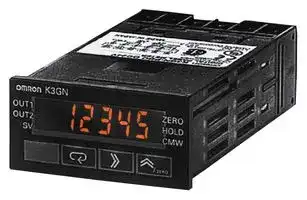


K3GNPDC24VDC
Digital Panel Meter, K3GN Series, DC Current, DC Voltage, 5 Digits, 20.4 Vdc to 26.4 Vdc
- Manufacturer: OMRON INDUSTRIAL AUTOMATION
- Product type: Digital Panel Meters
- No. of Digits / Alpha:5; Meter Function:DC Current / DC Voltage; Meter Range:0mA to 20mA, 4mA to 20mA, 0V to 5V, 1V to 5V, -5V to +5V, -10V to +10V; Digit Height:7mm; Panel Cutout Heig
- Meter Range: 0mA to 20mA, 4mA to 20mA, 0V to 5V, 1V to 5V, -5V to +5V, -10V to +10V
- Digit Height: 7mm
- Product Range: -
- Meter Function: DC Current / DC Voltage
- Panel Cutout Width: 45mm
- Supply Voltage Max: 26.4VDC
- Supply Voltage Min: 20.4VDC
- Panel Cutout Height: 22.2mm
- No. of Digits / Alpha: 5
- Operating Temperature Max: 55°C
- Operating Temperature Min: -10°C
| Delivery and price | |
|---|---|
| Units per pack | 1 |
| Price | 239.71 € |
| Current stock | 10+ |
| Lead time | 30 days |
**1/32 DIN Digital Panel Meter K3GN**

CSM_K3GN_DS_E_7_1

## **1/32 DIN Digital Panel Meter for Downsizing Equipment and Control Panels**

- Compact size: 48 x 24 x 82 (W x H x D).

- Multi-input compatible: DC voltage/current, rotary pulse.

- Two display colors (switchable): green/red.

- Selectable outputs.

- CE marking and UL/CSA approval.

- Splash-proof construction (NEMA4X: equivalent to IP66).

Refer to _Safety Precautions for All Digital Panel Meters_ .

For the most recent information on models that have been certified for safety standards, refer to your OMRON website.

## **Model Number Structure**

## ■ **Model Number Legend**

## **- - K3GN-** @@ @ @ **24 VDC**

**1 2 3 4**

## **1. Input Type**

ND: DC voltage/current, NPN

PD: DC voltage/current, PNP

**2. Output Type**

C: 2 relay contact outputs (SPST-NO)

- C-FLK: 2 relay contact outputs (SPST-NO) and RS-485 C-L1: 2 relay contact outputs (SPST-NO) and DC current (0 to 20 mA, 4 to 20 mA) C-L2: 2 relay contact outputs (SPST-NO) and DC voltage (0 to 5 V, 1 to 5 V, 0 to 10 V)

T1: 3 transistor outputs (NPN open collector)

T1-FLK: 3 transistor outputs (NPN open collector) and RS-485

- T1-L1: 3 transistor outputs (NPN open collector) and DC current (0 to 20 mA, 4 to 20 mA)

- T1-L2: 3 transistor outputs (NPN open collector) and DC voltage (0 to 5 V, 1 to 5 V, 0 to 10 V) T2: 3 transistor outputs (PNP open collector)

- T2-FLK: 3 transistor outputs (PNP open collector) and RS-485

## **3. Option**

None: None

- -400: Normally energized relays

## **4. Supply Voltage**

24 VDC: 24 VDC

**1** omrRon ~~a~~

**K3GN**

## **Orderin Information g**

## ■ **List of Models**

|**Supply**<br>**voltage**|**Input type**||**Output type**|**Model**|
|---|---|---|---|---|
|||**Judgement output**|**Data transmission output**||
|24 VDC|DC voltage, DC current,<br>or NPN input|2 relay contact outputs<br>(SPST-NO)|None|K3GN-NDC  24 VDC|
||||RS-485|K3GN-NDC-FLK  24 VDC|
||||DC current (0 to 20 mA, 4 to 20 mA)|K3GN-NDC-L1  24 VDC|
||||DC voltage (0 to 5 V, 1 to 5 V, 0 to 10 V)|K3GN-NDC-L2  24 VDC|
|||2 relay contact outputs<br>(SPST-NO)<br>Normally energized<br>relays (See note.)|None|K3GN-NDC-400  24 VDC|
||||RS-485|K3GN-NDC-FLK-400  24 VDC|
||||DC current (0 to 20 mA, 4 to 20 mA)|K3GN-NDC-L1-400  24 VDC|
||||DC voltage (0 to 5 V, 1 to 5 V, 0 to 10 V)|K3GN-NDC-L2-400  24 VDC|
|||3 transistor outputs (NPN<br>open collector)|<br>None|K3GN-NDT1  24 VDC|
||||RS-485|K3GN-NDT1-FLK  24 VDC|
||||DC current (0 to 20 mA, 4 to 20 mA)|K3GN-NDT1-L1  24 VDC|
||||DC voltage (0 to 5 V, 1 to 5 V, 0 to 10 V)|K3GN-NDT1-L2  24 VDC|
||DC voltage, DC current,<br>or PNP input|2 relay contact outputs<br>(SPST-NO)|None|K3GN-PDC  24 VDC|
||||RS-485|K3GN-PDC-FLK  24 VDC|
|||3 transistor outputs (PNP<br>open collector)|<br>None|K3GN-PDT2  24 VDC|
||||RS-485|K3GN-PDT2-FLK  24 VDC|


**Note:** Refer to page 5 for information on models with normally energized relays.

## **S ecifications p**

## ■ **Ratings**

|■**Ratings**|■**Ratings**|||
|---|---|---|---|
|**Item**||**K3GN-ND**<br>**With DC voltage, DC current, and NPN input**|**K3GN-PD**<br>**With DC voltage, DC current, and PNP input**|
|**Supply voltage**||24 VDC||
|**Operating voltage range**||85% to 110% of the rated supply voltage||
|**Power consumption (at max. load) (See note 1.)**||2.5 W max. (at max. DC load with all indicators lit)||
|**Input signal**||DC voltage, DC current, no-voltage contact, open collector||
|**DC voltage/current**<br>**input**|**A/D conversion**|Double integral method||
|**Pulse signal input**|**Pulse measurement**<br>**method**|Periodic measurement method||
|**External power supply**||None||
|**Control input**||Present value hold or forced zero (selectable) (See note 2.)||
|**Outputs**<br>**(Outputs depend on**<br>**the model.)**|**Relay contact output**|1 A, 30 VDC (resistive load), mechanical life: 50,000,000 operations min., electrical life: 100,000<br>operations min.||
||**Transistor output**|Max. load voltage: 24 VDC, Max. load current: 50 mA, Leakage current: 100μ A max.||
||**Communications output**|RS-485 (2-wire, half-duplex)||
||**Linear output**|DC current (0 to 20 mA DC, 4 to 20 mA: Load:<br>500Ωmax., Resolution: Approx. 10,000)<br>DC voltage (0 to 5 VDC, 1 to 5 VDC, 0 to 10 VDC:<br>Load: 5kΩmin., Resolution: Approx. 10,000)|---|
|**Display**||Negative LCD (backlit LCD) display<br>7-segment digital display, character height: 7.0 mm, and single illuminated display||
|**Main functions**||Scaling, prescaling, teaching, average processing, forced zero, display color selection, output type<br>selection, key protection, startup compensation timer, hysteresis||
|**Ambient temperature**||Operating:−10°C to 55°C (with no condensation or icing)<br>Storage:<br> −25°C to 65°C (with no condensation or icing)||
|**Ambient humidity**||Operating: 25% to 85%||
|**Altitude**||2,000 m max.||
|**Accessories**||Rubber packing, fixture, operation manual||


- **Note: 1.** A control power supply capacity greater than the rated capacity is required when the Digital Panel Meter is turned ON. Do not forget to take this into consideration when using several Digital Panel Meters. When power is supplied, all indicators will light and outputs will be OFF. When using startup compensation time operation, the display will read “00000” and all outputs will be OFF.

   **2.** Enabled only when using DC voltage/current input. (Min.time for control signal input: 80 ms)

**==> picture [539 x 34] intentionally omitted <==**

**2**

**K3GN**

## ■ **Characteristics**

|**Item**|**Item**|**K3GN-ND**<br>**With DC voltage, DC current, and NPN input**|**K3GN-PD**<br>**With DC voltage, DC current, and PNP input**|
|---|---|---|---|
|**Input signal**||DC voltage/current (4 to 20 mA, 1 to 5 V,±5 V,±10 V)<br>No-voltage contact (30 Hz max. with ON/OFF pulse width of 16 ms min.)<br>Open collector (5 kHz max. with ON/OFF pulse width of 90μs min.)||
|**Displayable range**||5 digits (-19999 to 99999)||
|**Sampling period**||250 ms||
|**Display refresh period**||Sampling period: 250 ms (at 4 Hz min.), 250×Number of averaging times (ms) (with average processing selected),<br>Input pulse cycle (at less than 4 Hz): Input pulse cycle×Number of averaging times||
|**Comparative output response**<br>**time**<br>**(transistor outputs)**||750 ms max. (transistor output)<br>(The time required for the judgment output to be output if the input signal rapidly changes from 15% to 95% or from 95% to 15%.)||
|**Linear output response time**||750 ms max. (The time required for the analog output to be<br>output if the output signal rapidly changes from 15% to 95% or<br>from 95% to 15%.)|---|
|**Insulation resistance**||20 MΩmin. (at 500 VDC) between external terminal and case.<br>Insulation provided between inputs, outputs, and power supply.||
|**Dielectric strength**||1,000 VAC for 1 min between external terminal and case.||
|**Noise immunity**||±480 V on power supply terminals in normal mode,±1,500 V in common mode,±1μs, or 100 ns for square-wave noise with 1 ns||
|**Vibration resistance**||Vibration frequency: 10 to 55 Hz, Acceleration: 50 m/s2for 10 min each in X, Y, and Z directions||
|**Shock resistance**||Models with transistor outputs: 150 m/s2three times each in 3 axes, 6 directions<br>Models with contact outputs: 100 m/s2three times each in 3 axes, 6 directions||
|**Weight**||Approx. 100 g (Main Unit only)||
|**Degree of**<br>**protection**|**Front panel**|NEMA4X for indoor use (equivalent to IP66),<br>IP20<br>IP00 and finger protection (VDE0106/100)||
||**Rear case**|||
||**Terminals**|||
|**Memory protection**||Non-volatile memory (EEPROM) (possible to rewrite 100,000 times)||
|**Approved standards**||UL508, CSA C22.2 No. 61010-1||
|**EMC**||(EMI)<br>EN 61326-1<br>Industrial electromagnetic environment<br>Emission Enclosure:<br>EN55011 Group 1 class A<br>(EMS)<br>EN 61326-1<br>Industrial electromagnetic environment<br>Immunity ESD:<br>EN 61000-4-2:<br>4 kV (contact discharge)<br>8 kV (air discharge)<br>Immunity RF-interference:<br>EN 61000-4-3:<br>10 V/m (amplitude-modulated,<br>80 MHz to 1 GHz)<br>Immunity Fast Transient Noise:<br>EN 61000-4-4:<br>2 kV (power line)<br>Immunity Burst Noise:<br>1 kV line to line (I/O signal line)<br>Immunity Surge:<br>EN 61000-4-5:<br>1 kV line to ground (power line)<br>Immunity Conducted Disturbance<br>EN 61000-4-6:<br>3 V (0.15 to 80 MHz)<br>Immunity Power Frequency Magnetic<br>EN 61000-4-8:<br>30 A/m (50 Hz) continuous time||


## ■ **Input Ranges: Measurement Range and Accuracy**

|**Input type**<br>in-t|||||**Analog**<br>analg|**Analog**<br>analg|**Analog**<br>analg|**Analog**<br>analg|**Analog**<br>analg|**Analog**<br>analg|**Analog**<br>analg|**Analog**<br>analg|**Analog**<br>analg|**Pulse**<br>pulse|**Pulse**<br>pulse|**Pulse**<br>pulse|**Pulse**<br>pulse|**Pulse**<br>pulse|**Remote**<br>rmt|
|---|---|---|---|---|---|---|---|---|---|---|---|---|---|---|---|---|---|---|---|
||**DC**<br>**current**<br>**input**||||**DC voltage input**|||||||||**Rotary pulse**||||||
|**Analog**<br>**range**<br>range|**4 to 20**<br>**mA**<br>4-20|||**Analog**<br>**range**<br>range|**1 to 5 V**<br>1-5|||±**5 V**<br>5|||±**10 V**<br>10|||**Pulse**<br>**frequency**<br>p-fre|**30 Hz**<br>30|**5 kHz**<br>5k|||Range of display<br>from:9999to<br>99999using<br>communications.|
|Connection<br>terminal|E-F|||Connection<br>terminal|D-E|||||||||Connection<br>terminal|B-C|||||
|Current range<br>(mA)<br>20.00<br>4.00<br>0.00||22.00||Voltage<br>range (V)10.00<br>5.000<br>0.000<br>−5.000<br>−10.00|||||||11.00|||Frequency<br>range<br>(Hz)<br>5000<br>4000<br>3000<br>2000<br>1000<br>0.0||5000||||
||||||5.500|||5.500||||||||||||
|||||||||||||||||||||
||||||0.000|||||||||||||||
|||||||||||||||||||||
|||||||||−5.500|||||||30.00|||||
|||0.00|||||||||−11.00||||0.05|0.05||||
|Input<br>impedance|60|Ω||Input<br>impedance|1 MΩmin.|||||||||---|||||---|
|Measurement<br>accuracy|±0.1% full scale ± one digit<br>23±3°C)||||max. (at|||±0.1% full scale ± one<br>digit max. (at 23±5°C)||||||±0.1% full scale ± one digit max. (at<br>23±5°C)|||||---|


**Note:** The shaded ranges indicate default settings.

**==> picture [539 x 34] intentionally omitted <==**

**3**

**K3GN**

## ■ **Input/Output Ratings**

## **Relay Contact Output**

|**Item**|**Resistive load (cos**φ**= 1)**|
|---|---|
|**Rated load**|1 A at 30 VDC|
|**Rated through current**|1 A max. (at COM terminal)|
|**Min. permissible load**<br>**(P level, reference value)**|10 mV, 10μA|
|**Mechanical life**|50,000,000 operations min.|
|**Electrical life**|100,000 operations min.|


## **Transistor Output**

|**Rated load voltage**|24 VDC|
|---|---|
|**Max. load current**|50 mA|
|**Leakage current**|100μA max.|


## **Communications Specifications**

|**Item**|**Item**|**RS-485**|
|---|---|---|
|**Communications method**||2-wire, half-duplex|
|**Synchronization method**||Start-stop synchronization|
|**Baud rate**||1,200/2,400/4,800/9,600/19,200 bps|
|**Transmission code**||ASCII|
|**Commu-**<br>**nications**|**Reading/**<br>**Writing to the**<br>**K3GN**|Read/write comparative set values,<br>read/write scaling values, enable/<br>disable the writing of data through<br>communications, forced-zero control,<br>and other data.|


## **Linear Output**

|**Item**|**0 to**<br>**20 mA**|**4 to**<br>**20 mA**|**0 to 5 V **|**1 to 5 V**|**0 to**<br>**10 V**|
|---|---|---|---|---|---|
|**Permissible load**<br>**impedance**|500Ωmax.||5 kΩmin.|||
|**Resolution**|Approx. 10,000|||||
|**Output error**|±0.5% full scale||±0.5 full scale.<br>±0.15 V at 1 V or less (no<br>output for 0 or less)|||


**==> picture [539 x 34] intentionally omitted <==**

**4**

**K3GN**

## **Nomenclature**

1. Main display 2. Status indicators

2. Status indicators 3. Level indicator

4. Level key

**==> picture [211 x 85] intentionally omitted <==**

5. Mode key 6. Shift key 7. Up/Zero key

|**Name**|**Name**||**Functions**|
|---|---|---|---|
|**1. Main display**|||Displays process values, parameters, and set values.|
|**2. Status indicators**||**OUT1**|Lit when output 1 is ON.|
|||**OUT2**|Lit when output 2 is ON.|
|||**SV**|Lit when a set value is beingdisplayed or changed.|
|||**T**|Lit when the teaching function is enabled. Flashes when the K3GN is in teaching operation.<br>Lit when a calibration value is being displayed during user calibration. Flashes while reading a calibra-<br>tion value.|
|||**ZERO**|Lit while the forced-zero function is activated.|
|||**HOLD**|Lit when HOLD input is ON.|
|||**CMW**|Lit when communications writingis “enabled” and is out when it is “disabled.”|
|**3. Level indicator**|||Displays the current level that the K3GN is in. (See below for details.)|
|**4. Level Key**|||Used to change the level.|
|**5. Mode Key**|||Used to allow the Main displayto indicateparameters sequentially.|
|**6. Shift Key**|||Used to enable that set value to be changed. When changing a set value, this key is used to move<br>alongthe digits.|
|**7. Up/Zero Key**|||Used to change a set value. Used to set or clear a forced-zero function when a measurement value is<br>beingdisplayed.|
|||||
|**Level indicator**||**Level**||
|p|Protect|||
|Not lit|Operation|||
|a|Adjustment|||
|s|Initial setting|||
|c|Communications setting|||
|f|Advanced function setting|||
|u|User calibration|||


## **Models with Normally Energized Relays K3GN-NDC-** @ **-400 24 VDC**

## **Relation between Output Type and Relay Output Operation**

- The drive operation for the output relay is reversed in these models.

- Relay contacts can be made open (i.e., OFF) when comparative set values are being judged. This is effective when constructing systems that take failsafe measures into consideration.values are being judged. This is effective when constructing systems

**==> picture [483 x 119] intentionally omitted <==**

**----- Start of picture text -----**<br>
Upper limit Upper and lower limits<br>that take failsafe measures into consideration.values are being judged. This is effective when constructing systems Set value Hysteresis Upper-limit set value Hysteresis<br>List of Models Measurement value Measurement Lower-limit value Hysteresis<br>set value<br>Models with Normally Energized Relays Output [ON] OFF Output [ON] OFF<br>K3GN-NDC-400  24 VDC<br>Lower limit Note: If Upper/Lower Limit is selected, the<br>K3GN-NDC-FLK-400  24 VDC upper limit and lower limit for the com-<br>parative set value can be set individu-<br>K3GN-NDC-L1-400  24 VDC Measurement value ally and will be displayed for OUT1and OUT2.<br>K3GN-NDC-L2-400  24 VDC Set value Hysteresis<br>Output [ON]<br>OFF<br>**----- End of picture text -----**<br>


## **List of Models**

**==> picture [539 x 34] intentionally omitted <==**

**5**

**K3GN**

## **Connections**

## ■ **Terminal Arrangement**

**==> picture [507 x 583] intentionally omitted <==**

**----- Start of picture text -----**<br>
Output terminals<br>a | a<br>Input terminals<br>NC NC<br>7 8<br>| foo OUT1 NC OUT2 COM<br>RS-485 9 10 11 12<br>C 7 8<br>B (+) A (−)<br>i C D [fae OUT1 PASS OUT2 COM<br>7 8 9 10 11 12<br>9 10 11 12<br>7 8 1 VN 2  LL] 3 4 5 6<br>(+) (−) D<br>A [OCHO O B =<br>OUT1 PASS OUT2 COM<br>9 10 11 12<br>1 2 3<br>tL<br>Operation<br>power supply<br>24 VDC oah C4<br>Event or pulse/contact input<br>A<br>1 2 3<br>Operation power supply  _f 4 5 6<br>24 VDC B COM<br>Voltage C urrent<br>Analog input<br>Event or pulse/contact input<br>Terminal No. Name Description<br>A-B Operation power Connect the operation power supply.<br>-<br>C B Event input or pulse/contact input Operates as follows depending on parameter<br>C-A setting:<br>• Holds process value.<br>• Calibrate the process value to zero and clear<br>the forced-zero function.<br>• Pulse or contact input.<br>D,F-E Analog input Connect the voltage or current analog input.<br>G-H Communications RS-485 communications terminals.<br>Linear output 0 to 20 mA DC, 4 to 20 mA DC<br>0 to 5 VDC, 1 to 5 VDC, 0 to 10 VDC<br>I,K-L Outputs Outputs relay or transistor outputs. There is<br>I,J,K-L also a PASS output for models with transistor<br>outputs.<br>Models without  communications<br>Models with  relay outputs<br>Models with<br>communications<br>Models with<br>Models with  linear output<br>NPN transistor outputs<br>Models with<br>PNP transistor outputs<br>Models with NPN inputs<br>Analog input<br>Models with PNP inputs<br>**----- End of picture text -----**<br>


**6**

**K3GN**

## ■ **Block Diagram**

**==> picture [478 x 279] intentionally omitted <==**

**----- Start of picture text -----**<br>
Key Display<br>Transistor output<br>A/D  (See note 1.)<br>Analog input  Input circuit conversion  Drive circuit<br>terminal circuit<br>Drive circuit Output circuit Linear output<br>(See note 2.)<br>EEPROM Micro-<br>computer Drive circuit Output circuit X Contact output (See note 3.)<br>Pulse/ Control  Control input  Waveform  Drive circuit Communica-tions driver Communications terminal (See note 4.)<br>input  circuit rectification<br>terminal circuit<br>Constant voltage circuit 1 Constant voltage circuit 2<br>Power supply circuit<br>Note:    1. Transistor output models only.<br>Operating power supply 2. Linear output models only.<br>**----- End of picture text -----**<br>


3. Relay output models only.

4. Models with communications functions only.

## ■ **Input Circuits**

## **Analog Input (DC Voltage/Current)**

Use terminal 5 for analog common.

**==> picture [244 x 75] intentionally omitted <==**

**----- Start of picture text -----**<br>
−  To A/D  −  To A/D<br>Voltage   4  +  Current   6  +<br>input  input<br>COM  5  COM  5<br>**----- End of picture text -----**<br>


## **Comparative Output**

## **Contact Output**

**==> picture [114 x 78] intentionally omitted <==**

**----- Start of picture text -----**<br>
5 V<br>X<br>OUT1<br>OUT2<br>**----- End of picture text -----**<br>


## **Transistor Output**

## **PNP Output**

## **NPN Output**

## **Pulse Input/ Event Input (HOLD/ZERO)**

- If analog input is selected, 2 and 3 will be the event inputs. Select Hold/Zero with event input allocation.

- Use terminal 2 for the common terminal.

- Use the NPN open collector or the no-voltage contacts for the control input.

## **NPN Input**

**==> picture [176 x 170] intentionally omitted <==**

**----- Start of picture text -----**<br>
24 VDC<br>1 24 V<br>2<br>2.35 kΩ<br>3<br>4.7 kΩ<br>24 VDC +<br>1<br>2.35 kΩ<br>3<br>Hold/Zero Pulse<br>4.7 kΩ<br>2<br>24 VDC −<br>**----- End of picture text -----**<br>


## **PNP Input**

**==> picture [243 x 76] intentionally omitted <==**

**----- Start of picture text -----**<br>
8.2 Ω<br>9 OUT1 12 COM<br>8.2 Ω 10 PASS 8.2 Ω 1 1 OUT2<br>8.2 Ω 8.2 Ω<br>11 OUT2 10 PASS<br>8.2 Ω<br>12 COM 9 OUT1<br>**----- End of picture text -----**<br>


**==> picture [539 x 34] intentionally omitted <==**

**7**

**K3GN**

## **Linear Output**

**==> picture [248 x 86] intentionally omitted <==**

**----- Start of picture text -----**<br>
Linear voltage output Linear current output<br>−<br>+ − +<br>7 7 +<br>5 kΩ  L + 500 Ω  L<br>min. 8 max. 8<br>− −<br>**----- End of picture text -----**<br>


**Note:** The commons for linear output and transistor output on models with L1 and L2 are connected internally.

Depending on how the common is wired for externally connected devices, unwanted current paths for the linear output signal in the circuit may prevent the output signal from being output.

When connecting an external device, externally connect a relay to the transistor output or provide another means of insulation.

**==> picture [539 x 34] intentionally omitted <==**

**8**

**K3GN**

## **O eratin Procedures p g**

## ■ **Initial Setting Flowchart**

## Power ON

Press the Level Key for 3 s min. to move to the initial setting level.

## **Input Type**

|**hart**<br>**Input Type**|||
|---|---|---|
|**Input type**|**Parameter**|**Function**|
|Analog|analg|Selects the DC voltage/current signal input.|
|Pulse|pulse|Selects the pulse input signal.|
|Remote|rmt|Displays the communications remote data from the<br>Programmable Controller.|


**Note:** The default value is analg: Analog input.

Select the input type and analog type (or pulse frequency). Set the scaling value and output type if required.

For models with communications, press the Level Key for less than 1 s to move to the communications setting level. Set the communications specification and press the Level Key for less than 1 s to move to the initial setting level.

## **Analog Input Type**

## **K3GN-ND** @

|**K3GN-ND**@|||
|---|---|---|
|**Input specification**|**Parameter**|**Setting range**|
|4 to 20 mA|4-20|Values from−19999 to 99999 can be displayed with scaling.<br>The position of the decimal point can be set as desired.|
|1 to 5 V|1-5||
|±5 V|5||
|±10 V|10||
|**Note:**The default value is4-20: 4 to 20 mA input range.<br>**K3GN-NL**@ (with Microvoltage Input)|||
|**Input specification**|**Parameter**|**Setting range**|
|±199.9 mV|199.9|Values from−19999 to 99999 can be displayed with scaling.<br>The position of the decimal point can be set as desired.|
|±19.99 mV|19.99||


**Note:** The default value is 199.9: ±199.9 mV input range.

If required, move to the advanced setting level and set parameters, such as the average processing, event input assignment, hysteresis value, auto-zero time, startup compensation time, and display color change.

## **Pulse Frequency**

|**Input specification**|**Parameter**|**Setting range**|
|---|---|---|
|0.05 Hz to 30.00 Hz|30|Values from−19999 to 99999 can be displayed with scaling.<br>The position of the decimal point can be set as desired.|
|0 Hz to 5 kHz|5k||


**Note:** The default value is 5k: 5 kHz input range.

Press the Level Key for 1 s min. to return to the operation level.

## **Setting Scaling**

## **Analog Input Signal**

(Refer to page 10 if a pulse input is selected.)

Set the values for OUT1 and OUT2.

Operation

- The scaling will be displayed on a line connecting two points by setting Display 1 for Input 1 and Display 2 for Input 2.

- The position of the decimal point can be set as desired. If the decimal point is to be displayed, it is necessary to consider the number of digits to be displayed past the decimal point when setting the scaling display value.

Note: When pulse input is used, the base point is the 0 point, so the settings are only the input value and the display value.

**==> picture [346 x 132] intentionally omitted <==**

**----- Start of picture text -----**<br>
Displayed  Displayed<br>value value<br>Display 2 Display 2<br>Display 1 Display 1<br>Input 1 Input 2 Input 2 Input 1<br>Input value Input value<br>**----- End of picture text -----**<br>


Instead of setting by inputting with the Shift Key and Up Key, current measurement values van be input as scaling input values for teaching. This is useful for making settings while checking the operation status of the K3GN.

For details on the operating procedures, refer to the _K3GN Digital Panel Meter Manual_ (Cat. No. N102).

**==> picture [539 x 34] intentionally omitted <==**

**9**

**K3GN**

**•** If the K3GN is used with a pulse signal input, the display value will be the input frequency if scaling is not performed. Display the rate of rotation or the speed of a device or machine to which the K3GN is mounted by converting using scaling. The relation between input f (Hz) and display D is expressed in the form D = f x a (factor). The value depends on the display unit. The formula will be comprised as follows:

Display using rpm: D = f x 1/N x 60, N = Number of pulses per rotation, f = Input pulse frequency (Hz) (i.e., number of pulses in one second) Display using m/min: D = f x π d x 1/N x 60, π d = Circumference length (m) per rotation

**==> picture [215 x 116] intentionally omitted <==**

**----- Start of picture text -----**<br>
Display value D<br>Display value<br>0<br>0 Input value Input value f (Hz)<br>**----- End of picture text -----**<br>


## **Prescaling Example**

**==> picture [177 x 52] intentionally omitted <==**

**----- Start of picture text -----**<br>
Pulse<br>K3GN<br>**----- End of picture text -----**<br>


To display the rotational speed of a device that outputs five pulses per rotation:

D = f × 1/5 × 60, and,

If f=1,

D = 12, so

The setting will be completed by inputting inp:1 and dsp:12.

## **Output 1 Type**

## **Output 2 Type**

|**Output**<br>**type**|**Parameter**|**Function**||**Output**<br>**type**|**Parameter**|**Function**|
|---|---|---|---|---|---|---|
|Upper limit|hi|Output turns ON if the<br>measurement value≥comparative<br>set value 1.||Upper limit|hi|Output turns ON if the<br>measurement value≥comparative<br>set value 2.|
|Lower limit|lo|Output turns ON if the<br>measurement value≤comparative<br>set value 1.||Lower limit|lo|Output turns ON if the<br>measurement value≤comparative<br>set value 2.|
|Upper and<br>lower<br>limits|hi-lo|The comparative upper-limit set<br>value and comparative lower-limit<br>set value can be set separately and<br>expressed high and low.<br>Output turns ON if the<br>measurement value≥comparative<br>upper-limit set value 1 or if the<br>measurement value is≤<br>comparative lower-limit set value 1.||Upper and<br>lower limit|hi-lo|The comparative upper-limit set<br>value and comparative lower-limit<br>set value can be set separately and<br>expressed high and low.<br>Output turns ON if the<br>measurement value≥comparative<br>upper-limit set value 2 or if the<br>measurement value is≤<br>comparative lower-limit set value 2.|


**Note:** The default value is hi: Upper limit.

## **Upper Limit**

## **Lower Limit**

**Note:** The default setting is lo: Lower limit.

## **Upper and Lower Limits**

**==> picture [503 x 71] intentionally omitted <==**

**----- Start of picture text -----**<br>
Comparative<br>Comparative set value Hysteresis upper-limit set value Hysteresis<br>Measurement value Measurement value Measurement value<br>Comparative set value Hysteresis Comparative  Hysteresis<br>lower-limit set value<br>ON ON ON<br>Comparative output Comparative output Comparative output<br>OFF OFF OFF<br>**----- End of picture text -----**<br>


The output operations can be selected separately for OUT1 and OUT2.

## **Upper Limit 2-stage Output**

## **Threshold Output**

## **Combination of Upper Limit and Upper/**

**==> picture [508 x 150] intentionally omitted <==**

**----- Start of picture text -----**<br>
Lower Limits<br>Comparative upper-<br>Comparative  limit set value 2 Comparative upper-<br>set value 2 limit set value 2<br>Comparative upper-<br>Comparative<br>limit set value 1<br>set value 1<br>Comparative lower-<br>Comparative set value 1 limit set value 1Comparative upper-limit set value 2 Comparative upper-limit set value 2<br>Comparative ON ON ON<br>2 output OFF Comparative  OFF Comparative  OFF<br>2 output 2 output<br>Comparative ON Comparative  ON Comparative  ON<br>1 output OFF 1 output OFF 1 output OFF<br>PASS ON PASS ON PASS ON<br>(Transistor  OFF (Transistor  OFF (Transistor  OFF<br>output  output  output<br>models only) models only) models only)<br>**----- End of picture text -----**<br>


**==> picture [539 x 34] intentionally omitted <==**

**10**

**K3GN**

## **Linear Output Type**

|**Linear output**<br>**type**|<br>**Parameter**|**Meaning of set value**|
|---|---|---|
|Linear current<br>type|0-20|Linear current type: 0 to 20 mA|
||4-20|Linear current type: 4 to 20 mA|
|Linear voltage<br>type|0-5|Linear voltage type: 0 to 5 V|
||1-5|Linear voltage type: 1 to 5 V|
||0-10|Linear voltage type: 0 to 10 V|


**==> picture [539 x 34] intentionally omitted <==**

**11**

**K3GN**

## **Settin Menu and Parameters g**

**==> picture [456 x 281] intentionally omitted <==**

**----- Start of picture text -----**<br>
Power ON<br>+ key<br>at least the user-set time<br>Operation level Adjustment level Protect<br>       key<br>less than 1 s + keys<br>1 s min.<br>       key        key<br>1 s min. 3 s min.<br>Initial setting level Communications<br>       key setting level<br>less than 1 s<br>Measurement in progress<br>       key<br>Password input<br>1 s min. Measurement stopped<br>Advanced function<br>Not displayed for some models.<br>setting level<br>Level change<br>Password input<br>Measurement is stopped in the setting level.<br>At that time all outputs will turn OFF.<br>Calibration level<br>**----- End of picture text -----**<br>


**==> picture [187 x 53] intentionally omitted <==**

**----- Start of picture text -----**<br>
 key less than 1 s<br>Adjustment level<br>Communications<br>writing /<br>**----- End of picture text -----**<br>


## ~~Changing Set Values~~

While the parameter is being displayed, press the      Key to display the set value.

**==> picture [236 x 147] intentionally omitted <==**

**----- Start of picture text -----**<br>
Monitor Status<br>Press the      Key again to enter the status for setting.<br>Setting Status<br>The part to be changed will flash.<br>Make the required setting, then press the      Key. The system will<br>switch to the next parameter and the set value will be registered.<br>Monitor status Setting status<br>Change the set<br>value using the<br>SV will flash.             Keys.<br>To the next parameter If 5 s lapses without any key being<br>pressed, the set value will be registered,<br>and the system will return to monitor status.<br>**----- End of picture text -----**<br>


**==> picture [211 x 293] intentionally omitted <==**

**----- Start of picture text -----**<br>
Power ON<br>Operation level<br>Present value<br>Comparative<br>set value 1 to<br>Select<br>either. Comparative<br>upper-limit  to<br>set value 1<br>Comparative<br>lower-limit  to<br>set value 1<br>Comparative<br>set value 2 to<br>Select<br>either. Comparative<br>upper-limit  to<br>set value 2<br>Comparative<br>lower-limit  to<br>set value 2<br>**----- End of picture text -----**<br>


**==> picture [539 x 34] intentionally omitted <==**

**12**

**K3GN**

**==> picture [545 x 692] intentionally omitted <==**

**----- Start of picture text -----**<br>
 key less than 1 s<br>Communications setting level<br>Communications<br>unit No. ,  to<br> key 1 s min.<br>Baud rate / / /<br> key 3 s min. / kbps<br>Initial setting level<br> key 1 s min. Data bits /<br>Analog:<br>Input type Pulse:<br>Remote:<br>K3GN-ND@ Stop bits /<br>/ / /<br>Analog input Analogmodel<br>K3GN-NL@ (Microvoltage input) Parity None:<br>/ Even:<br>Odd:<br>Pulse<br>Pulse input frequency / Hz<br> key 1 s min.<br>Analog input Scalinginput   to  Advanced setting level<br>value 1 Enter password<br>"-0169"<br>Scalingdisplay   to  Parameter initialization /<br>value 1<br>Average<br>Scaling / / /  times<br>input   to  processing<br>value 2<br>Scaling Analog input Event inputallocation /<br>display   to<br>value 2<br>Pulse input Scaling  to  Comparative1 hysteresis  to   to<br>input value<br>Scaling display   to  Comparative 2 hysteresis  to   to<br>value<br>Decimal point   to  Pulse input Auto-zero time  to  s<br>position<br>Comparative  Upper limit: Startup<br>1 type Lower limit:Upper and  compensation time  to  s<br>lower limits:<br>Green (red):<br>Comparative  Upper limit: Display  Green:<br>2 type Lower limit:Upper and  color change Red (green):<br>lower limits:  Red:<br>Linear  Display<br>current / auto-return  to   to  s<br>time<br>Linear  Move-to-<br>voltage / / protect   to   to  s<br>level time<br>Linear<br>output  to  Send<br>upper-limit  waiting time  to   to  ms<br>set value<br>Linear<br>output  to  Move to<br>lower-limit  calibration   to  to<br>set value level<br>Move to<br>advanced   to  to<br>setting level<br>**----- End of picture text -----**<br>


The highlighted values indicate default settings.

**==> picture [539 x 34] intentionally omitted <==**

**13**

**K3GN**

**==> picture [81 x 18] intentionally omitted <==**

**----- Start of picture text -----**<br>
Protect level<br>**----- End of picture text -----**<br>


**==> picture [71 x 133] intentionally omitted <==**

**==> picture [405 x 127] intentionally omitted <==**

**----- Start of picture text -----**<br>
Operation/<br>adjustment / / Restricts menu display and writing in the operation level and adjustment level.<br>protection<br>Initial setting/<br>communications / / Restricts menu display and moving for the initial setting level, communications<br>protection setting level, and advanced setting level.<br>Setting<br>change / Restricts changes to setup by operating the keys on the front panel.<br>protection<br>Forced-zero / Restricts forced-zero operation by operating the keys on the front of the panel.<br>protection<br>(This item is not displayed if pulse input is used.)<br>**----- End of picture text -----**<br>


## **Operation/Adjustment Protection**

Restricts key operation in the operation level and adjustment level.

|**Setting**|**Operation level**<br>**Present value**<br>**display**<br>**Comparative**<br>**value display**|**Operation level**<br>**Present value**<br>**display**<br>**Comparative**<br>**value display**|**Moving to**<br>**adjustment**<br>**level**|
|---|---|---|---|
|||**Comparative**<br>**value display**||
|0|Allowed|Allowed|Allowed|
|1|Allowed|Allowed|Prohibited|
|2|Allowed|Prohibited|Prohibited|


- The default setting is 0.

- Protection is not enabled when the setting is 0 (initial setting).

## **Setting Change Protection**

Restricts changes to settings.

|**Setting**|**Details**|
|---|---|
|OFF|Changes to settings using the keys are allowed.<br>(Movingto settingstatus is allowed.)|
|ON|Changes to settings using the keys are prohibited.<br>(Movingto settingstatus is prohibited.)|


- The default setting is OFF.

**Note:** Changes to protection level parameters, moving to advanced function setting level, and moving to calibration level are all allowed.

## **Initial Setting/Communications Protection**

Restricts moving to the initial setting level, communications setting level, and advanced function setting level.

|**Setting**|**Moving to initial setting level**|**Moving to**<br>**communications**<br>**level**|
|---|---|---|
|0|Allowed (message for moving to<br>advanced function setting level<br>displayed)|Allowed|
|1|Allowed (message for moving to<br>advanced function setting level not<br>displayed)|Allowed|
|2|Prohibited|Prohibited|


- The default setting is 1.

## **Forced-zero Protection**

Restricts the executing or clearing of a forced zero by using the keys.

|**Setting**|**Details**|
|---|---|
|OFF|Executingor clearingof forced zero allowed.|
|ON|Executingor clearingof forced zero prohibited.|


- The default setting is OFF.

## ■ **Error Displays (Troubleshooting)**

If an error occurs, error information will be displayed on the main display. Check the error according to the display and correct the error as indicated.

|**Main display**|**Level display**|**Error details**|**Correction**|
|---|---|---|---|
|e111(E111)|Not lit|Memory error: RAM|Cycle the power supply. If the display does not change, replacement is<br>required. If the error is removed, the original error may have been<br>caused by noise. Check that there are no possible sources of noise<br>nearby.|
|e111(E111)|s|Memory error: EEP||
|s.err(S.Err)<br>flashing|Not lit|Input error or input<br>range exceeded.|The outputs will all turn OFF.<br>Check that the input wiring is correct, that there is no disconnection, or<br>short-circuit,and that the input type is correct. Alternatively,limit the|
|99999<br>flashing|Not lit|Display range over:<br>Upper limit|This is not an error. It is displayed when the display range is exceeded<br>even if the present value is within the input range and control range.<br>Limit the input value and display value to within the range.|
|:9999<br>Flashing|Not lit|Display range over:<br>Lower limit||


**==> picture [539 x 34] intentionally omitted <==**

**14**

**K3GN**

## **O eration p**

## ■ **Main Functions**

## **Scaling**

The K3GN includes a scaling function that can convert the input signal to a desired value and display that value.

The displayed values can be freely adjusted to shift values, to create reversed displays, or to create positive/negative displays.

**==> picture [241 x 98] intentionally omitted <==**

**----- Start of picture text -----**<br>
Display Display<br>value value<br>DISPLAY2 DISPLAY2<br>DISPLAY1 DISPLAY1<br>INPUT1 INPUT2 INPUT1 INPUT2<br>( ) ( ) Input value Input<br>value<br>**----- End of picture text -----**<br>


## **Key Protection**

Key protection is used to restrict changes to displays and settings using the front panel keys and to restrict menu display and movement of operation levels. This function is effective for preventing misuse during operation.

## **Startup Compensation Time (Rotary Pulse Input Only)**

The startup compensation time parameter keeps the measurement operation from sending an unnecessary output corresponding to instantaneous, fluctuating input from the moment the K3GN is turned ON until the end of the preset period.

## **Hysteresis**

The hysteresis of comparative outputs can be set to prevent the chattering of relay or transistor outputs.

## **Teaching**

Teaching is used when using scaling or setting comparative set values to set the present measurement values as the set values instead of inputting with the Shift and Up/Zero Keys. Teaching is useful for making settings while checking the operation status of the K3GN.

## **Average Processing**

Average processing can be performed for measurement values using four levels (OFF, 2 times, 4 times, or 8 times). Average processing stabilizes displayed values by averaging the corresponding input signals that fluctuate dynamically. Select the appropriate number of averaging times depending on the application.

## **Forced-zero Function**

It is possible to shift from a value to the zero point with one touch of the Up/Zero Key on the front panel (for example, when adjusting reference values).

**Note:** This function can be used only when forced-zero operation protection is released.

**==> picture [133 x 77] intentionally omitted <==**

**----- Start of picture text -----**<br>
K3GN<br>OUT1- -ZERO<br>OUT2- -HOLD<br>SV- -CMW<br>/ZERO<br>**----- End of picture text -----**<br>


## **Changing the Display Color**

The color of the value displayed can be set to either red or green. Make the setting according to the purpose and application of the equipment in which the K3GN is installed. The display color can also be set to change from green to red, or from red to green, according to the status of the comparison criteria.

## **Output Type Selection**

Output operation for comparative set values can be freely selected. Upper limit: Output ON if the measurement value ≥ comparative set value.

Lower limit: Output ON if the measurement value ≤ comparative set value.

Upper/lower limit: Output ON if the measurement value ≥ comparative upper-limit set value or if the measurement value is ≤ the comparative lower-limit value.

**==> picture [539 x 34] intentionally omitted <==**

**15**

**K3GN**

## **Dimensions**

**Note:** All units are in millimeters unless otherwise indicated.

**==> picture [508 x 246] intentionally omitted <==**

**----- Start of picture text -----**<br>
K3GN Panel Cutout Dimensions<br>Separate mounting Gang mounting<br>+0.6 (48 × No. of Panels − 2.5) [+1.0] 0<br>45 0<br>44.8 22.2 +0.30 22.2 +0.30<br>40 min.<br>The products cannot be<br>made waterproof when<br>gang-mounted.<br>Mounting Recommended Panel Thickness 1 to 5 mm.<br>K3GN Mount the product horizontally.<br>OUT1-OUT2- T -ZERO-HOLD<br>35 24 SV- -CMW 22 • For installation, insert the K3GN<br>/ZERO panel into the rectangular hole,<br>insert the adaptor from the rear, and<br>48 80 push it in to reduce the gap between<br>2 the panel surface and the adaptor.<br>The K3GN uses M3 terminals. A terminal  Secure the Unit with the screws.<br>cover is provided. For water-proof installation, insert<br>the rubber gasket onto the body of<br>Main Display Character Size the K3GN.<br>• If multiple mounted Units are used,<br>7 mm make sure the ambient temperature<br>for the K3GN does not exceed the<br>specified temperature.<br>3.6 mm<br>-<br>-- ---<br>**----- End of picture text -----**<br>


## **Installation**

## ■ **Rubber Packing**

**1.** Insert the K3GN into the panel cut-out hole.

**2.** For a waterproof installation, insert the rubber gasket onto the body of the K3GN.

The Rubber Packing ensures a waterproof level conforming to NEMA4X. Depending on the operating environment, deterioration, contraction, or hardening of the Rubber Packing may occur, making replacement necessary. Contact your OMRON representative if replacement is required.

**==> picture [158 x 90] intentionally omitted <==**

**----- Start of picture text -----**<br>
Rubber packing<br>**----- End of picture text -----**<br>


## ■ **Wiring Precautions**

   - Wire the power supply with the correct polarity. Wiring with incorrect polarity may result in damage or burning.

   - Wire the terminals using crimp terminals.

**3.** Fit the adaptor into the grooves on the left and right sides of the rear case, then push it until it contacts the panel to secure the K3GN.

- Tighten terminal screws to a torque of approx. 0.5 N·m.

- Wire signal lines and power lines separately to reduce the influence of noise.

**==> picture [348 x 196] intentionally omitted <==**

**----- Start of picture text -----**<br>
Adaptor<br>■ Wiring<br>Power Supply<br>•<br>1<br>24 VDC<br>2<br>•<br>The K3GN is designed to provide the best visibility at the angles<br>shown in the following diagram.<br>5.8 mm max.<br>40°<br>5.8 mm max.<br>20°<br>**----- End of picture text -----**<br>


- Input 24 VDC to terminals 1 and 2.

## **Angle of View**

- Use M3 crimp terminals of the type shown below.

The K3GN is designed to provide the best visibility at the angles shown in the following diagram.

**==> picture [539 x 34] intentionally omitted <==**

**16**

**K3GN**

## **Measurement Input**

The following table shows the relation between input ranges and input terminals.

|input terminals.|input terminals.||
|---|---|---|
|**Input range**||**Input terminals**|
|DC voltage/DC current|4 to 20 mA|E-F|
||1 to 5 V|D-E|
||±5 V||
||±10 V||
|No-voltage contacts and NPN<br>(Models with NPN inputs)|open collector|B-C|
|No-voltage contacts and PNP<br>(Models with PNP inputs)|open collector|A-C|


Be sure to read the Precautions for Correct Use and other information required when using the K3GN in the following user’s manual.

K3GN Digital Panel Meter User’s Manual (Cat.No. N102)

ALL DIMENSIONS SHOWN ARE IN MILLIMETERS.

To convert millimeters into inches, multiply by 0.03937. To convert grams into ounces, multiply by 0.03527.

In the interest of product improvement, specifications are subject to change without notice.

**==> picture [539 x 34] intentionally omitted <==**

**17**

## Terms and Conditions Agreement

## Read and understand this catalog.

Please read and understand this catalog before purchasing the products.  Please consult your OMRON representative if you have any questions or comments.

## Warranties.

(a) Exclusive Warranty. Omron’s exclusive warranty is that the Products will be free from defects in materials and workmanship for a period of twelve months from the date of sale by Omron (or such other period expressed in writing by Omron). Omron disclaims all other warranties, express or implied.

(b) Limitations. OMRON MAKES NO WARRANTY OR REPRESENTATION, EXPRESS OR IMPLIED, ABOUT NON-INFRINGEMENT, MERCHANTABILITY OR FITNESS FOR A PARTICULAR PURPOSE OF THE PRODUCTS. BUYER ACKNOWLEDGES THAT IT ALONE HAS DETERMINED THAT THE

PRODUCTS WILL SUITABLY MEET THE REQUIREMENTS OF THEIR INTENDED USE.

Omron further disclaims all warranties and responsibility of any type for claims or expenses based on infringement by the Products or otherwise of any intellectual property right. (c) Buyer Remedy. Omron’s sole obligation hereunder shall be, at Omron’s election, to (i) replace (in the form originally shipped with Buyer responsible for labor charges for removal or replacement thereof) the non-complying Product, (ii) repair the non-complying Product, or (iii) repay or credit Buyer an amount equal to the purchase price of the non-complying Product; provided that in no event shall Omron be responsible for warranty, repair, indemnity or any other claims or expenses regarding the Products unless Omron’s analysis confirms that the Products were properly handled, stored, installed and maintained and not subject to contamination, abuse, misuse or inappropriate modification. Return of any Products by Buyer must be approved in writing by Omron before shipment. Omron Companies shall not be liable for the suitability or unsuitability or the results from the use of Products in combination with any electrical or electronic components, circuits, system assemblies or any other materials or substances or environments. Any advice, recommendations or information given orally or in writing, are not to be construed as an amendment or addition to the above warranty.

See http://www.omron.com/global/ or contact your Omron representative for published information.

## Limitation on Liability; Etc.

OMRON COMPANIES SHALL NOT BE LIABLE FOR SPECIAL, INDIRECT, INCIDENTAL, OR CONSEQUENTIAL DAMAGES, LOSS OF PROFITS OR PRODUCTION OR COMMERCIAL LOSS IN ANY WAY CONNECTED WITH THE PRODUCTS, WHETHER SUCH CLAIM IS BASED IN CONTRACT, WARRANTY, NEGLIGENCE OR STRICT LIABILITY. Further, in no event shall liability of Omron Companies exceed the individual price of the Product on which liability is asserted.

## Suitability of Use.

Omron Companies shall not be responsible for conformity with any standards, codes or regulations which apply to the combination of the Product in the Buyer’s application or use of the Product. At Buyer’s request, Omron will provide applicable third party certification documents identifying ratings and limitations of use which apply to the Product. This information by itself is not sufficient for a complete determination of the suitability of the Product in combination with the end product, machine, system, or other application or use. Buyer shall be solely responsible for determining appropriateness of the particular Product with respect to Buyer’s application, product or system. Buyer shall take application responsibility in all cases.

NEVER USE THE PRODUCT FOR AN APPLICATION INVOLVING SERIOUS RISK TO LIFE OR PROPERTY OR IN LARGE QUANTITIES WITHOUT ENSURING THAT THE SYSTEM AS A WHOLE HAS BEEN DESIGNED TO ADDRESS THE RISKS, AND THAT THE OMRON PRODUCT(S) IS PROPERLY RATED AND INSTALLED FOR THE INTENDED USE WITHIN THE OVERALL EQUIPMENT OR SYSTEM.

## Programmable Products.

Omron Companies shall not be responsible for the user’s programming of a programmable Product, or any consequence thereof.

## Performance Data.

Data presented in Omron Company websites, catalogs and other materials is provided as a guide for the user in determining suitability and does not constitute a warranty. It may represent the result of Omron’s test conditions, and the user must correlate it to actual application requirements. Actual performance is subject to the Omron’s Warranty and Limitations of Liability.

## Change in Specifications.

Product specifications and accessories may be changed at any time based on improvements and other reasons. It is our practice to change part numbers when published ratings or features are changed, or when significant construction changes are made. However, some specifications of the Product may be changed without any notice. When in doubt, special part numbers may be assigned to fix or establish key specifications for your application. Please consult with your Omron’s representative at any time to confirm actual specifications of purchased Product.

## Errors and Omissions.

Information presented by Omron Companies has been checked and is believed to be accurate; however, no responsibility is assumed for clerical, typographical or proofreading errors or omissions.

**In the interest of product improvement, specifications are subject to change without notice.**

## **OMRON Corporation**

## **Industrial Automation Company**

2016.9

**http://www.ia.omron.com/**

(c)Copyright OMRON Corporation 2016 All Right Reserved.
Updated at June 9, 2026
With a legacy spanning over 80 years, Omron Industrial Automation is a globally recognized leader in the manufacture of advanced industrial control and automation components. Renowned for their reliability and engineering excellence, Omron delivers comprehensive solutions that enhance efficiency, machine safety, and precision across a wide range of manufacturing environments. Our extensive portfolio of Omron products is heavily focused on their industry-leading sensing and switching technologies. We offer a vast selection of sensors, excelling specifically in high-performance proximity sensors, light sensors, and temperature sensors. Complementing this range are robust switching solutions, featuring a deep inventory of power relays, solid-state relays, safety relays, and essential relay accessories designed for demanding operational requirements. Beyond sensing and switching, Omron is highly regarded for its precision automation and process control equipment. Our selection features highly accurate temperature controllers, versatile process controllers, and sophisticated panel displays and instrumentation. To support these fundamental systems, we also supply dependable Omron power supplies, notably AC/DC converters, alongside vital connectivity components like DIN rail terminal blocks to ensure secure, efficient, and complete industrial setups.
About Novapart
Novapart is a B2B electronic component broker specialising in stock shortages and cost reduction. We source hard-to-find parts and identify compliant alternatives across a catalogue of 410,000+ components from 500+ manufacturers.
Learn more →Stock Shortage Specialist
When a component is unavailable, discontinued or has an unacceptable lead time, we tap into our network of vetted European and Asian distributors to source what you need — without compromising on quality or traceability.
Request a quote →Compliant Alternatives
We identify pin-to-pin, electrically equivalent substitutes that meet the same certifications (RoHS, AEC-Q100, REACH) as your original specification — validated against datasheets, not just part numbers. Often at a lower cost.
BOM Analysis service →