
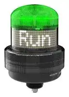


K100PDBLRGBSQ
Indicator, Modbus, Multicolour, 30 VDC, IP66, IP69K, 134.62 mm H, 118.62 mm Lens, -40 to 50° C
- Manufacturer: BANNER ENGINEERING
- Product type: Visual Signal Indicator Units
- SVHC: No SVHC (25-Jun-2025)
- Power Rating: -
- Lens Diameter: 118.62mm
- Product Range: K100 Pro Series
- External Height: 5.3"
- IP / NEMA Rating: IP66, IP69K
- Module Lens Colour: Multicolour
- Supply Voltage VAC: -
- Supply Voltage VDC: 30V
- Visual Signal Type: Multifunction
- Operating Temperature Max: 50°C
- Operating Temperature Min: -40°C
| Delivery and price | |
|---|---|
| Units per pack | 1 |
| Price | 386.34 € |
| Current stock | 10+ |
| Lead time | 30 days |
**==> picture [148 x 792] intentionally omitted <==**

K100 Programmable Display Beacon with Modbus® Product Manual

Original Instructions p/n: 248446 Rev. A 02-Sep-25

© Banner Engineering Corp. All rights reserved. www.bannerengineering.com

K100 Programmable Display Beacon with Modbus® Product Manual

## Contents

**Chapter 1 Features.................................................................................................................. 3** 1.1 Models ..................................................................................................................................................................................................... 3 **Chapter 2 Wiring...................................................................................................................... 4**

**Chapter 3 Modbus Register Map ........................................................................................... 5** 3.1 Holding Register Column Definitions....................................................................................................................................................... 5 3.2 Device Information................................................................................................................................................................................... 5 3.3 Modbus Configuration ............................................................................................................................................................................. 6 3.4 Operation Mode....................................................................................................................................................................................... 6 3.4.1 Run Mode ...................................................................................................................................................................................... 7 3.4.2 Message Mode .............................................................................................................................................................................. 9 3.4.3 Level Mode .................................................................................................................................................................................. 13 3.4.4 Timer Mode.................................................................................................................................................................................. 26 3.4.5 Counter Mode .............................................................................................................................................................................. 40 3.5 Display Settings..................................................................................................................................................................................... 53 3.6 Custom Settings .................................................................................................................................................................................... 53 3.6.1 Custom Color 1 Configuration ..................................................................................................................................................... 54 3.6.2 Custom Color 2 Configuration ..................................................................................................................................................... 54 3.6.3 Custom Audio Settings ................................................................................................................................................................ 54 **Chapter 4 Specifications ...................................................................................................... 55** 4.1 FCC Part 15 Class B for Unintentional Radiators.................................................................................................................................. 56 4.2 Industry Canada ICES-003(B)............................................................................................................................................................... 56 4.3 Dimensions............................................................................................................................................................................................ 57 **Chapter 5 Accessories.......................................................................................................... 58** 5.1 Cordsets ................................................................................................................................................................................................ 58 5.2 Brackets................................................................................................................................................................................................. 58 5.3 Elevated Mount System......................................................................................................................................................................... 59 **Chapter 6 Product Support and Maintenance .................................................................... 60** 6.1 UTF-8 Encoding Table and Unicode Characters................................................................................................................................... 60 6.2 Clean with Mild Detergent and Warm Water ......................................................................................................................................... 64 6.3 Repairs .................................................................................................................................................................................................. 64 6.4 Contact Us............................................................................................................................................................................................. 64 6.5 Banner Engineering Corp Limited Warranty.......................................................................................................................................... 64

© Banner Engineering Corp. All rights reserved. www.bannerengineering.com

K100 Programmable Display Beacon With Modbus® Product Manual

Chapter Contents

1.1 Models............................................................................................................................................................................................................ 3

## Chapter 1

## Features

The K100 Programmable Display Beacon with Modbus provides diagnostics and indication for control engineers and OEMs who need to improve the interaction between operators and equipment to drive response speed and productivity improvements.

- Easily configurable, versatile display can be installed nearly anywhere, making it a simple yet powerful alternative to complex HMIs and other displays

- Great for displaying takt time, equipment status, assembly sequences, counts, and measurements where they are most useful

- Modbus® control allows access to full color and advanced animations

- Quick and easy configuration—simply define the desired text and call it via discrete control or process data

- Bright white LED display and multicolored beacon LEDs legible from 10 meters away inform operators about exactly what is going on so they can respond quickly and accurately

- IP66- and IP69K per ISO 20653-rated polycarbonate housing resists impact and condensation to provide clear communication in challenging and changing environmental conditions

- Wireless communication facilitates remote monitoring and control

## 1.1 Models

**==> picture [494 x 68] intentionally omitted <==**

**----- Start of picture text -----**<br>
||||||||||
|---|---|---|---|---|---|---|---|---|
|Table 1.|Model Key|
|Series|Style|Type|Voltage|Color|Control|Audible|Connector|[(1)]|
|K100P|D|BL|RGB|S|Q|
|Blank = No|Q = Integral 4-pin|
|K100P = K100 Pro|D = Display|BL = Beacon Light|Blank = DC|RGB = Multicolor|S = Modbus|Audible|M12 male quick-disconnect|
|A = Audible|connector|

**----- End of picture text -----**<br>


> (1) Models with a quick-disconnect connector require a mating cordset.

02-Sep-25

© Banner Engineering Corp. All rights reserved. www.bannerengineering.com

page 3 of 65

K100 Programmable Display Beacon With Modbus® Product Manual

## Chapter Contents

## Chapter 2

## Wiring

- Table 2. Modbus Wiring 4-Pin Male M12 Pinout Pinout Key and Wiring 1. Brown - 12 V DC to 30 V DC

- 1

- 2 2. White - RS-485 (+) 4 3. Blue - DC Common

- 3 4. Black - RS-485 (-)

02-Sep-25

© Banner Engineering Corp. All rights reserved. www.bannerengineering.com

page 4 of 65

K100 Programmable Display Beacon With Modbus® Product Manual

## Chapter Contents

3.1 Holding Register Column Definitions.............................................................................................................................................................. 5 3.2 Device Information ......................................................................................................................................................................................... 5 3.3 Modbus Configuration .................................................................................................................................................................................... 6 3.4 Operation Mode.............................................................................................................................................................................................. 6 3.5 Display Settings............................................................................................................................................................................................ 53 3.6 Custom Settings........................................................................................................................................................................................... 53

## Chapter 3 Modbus Register Map

## 3.1 Holding Register Column Definitions

## Base 0 Address

Registers are addressed with the first register starting at zero

## Base 1 Address

Registers are addressed with the first register starting at one

Description

Lists the functionality of the register

## Holding Register Representation

Lists the allowed values of the register and the definition of those values

## Default Value

Lists the factory default value of the register

## Saved

Yes: The register value is stored in non-volatile memory, and is preserved when power is cycled No: The register value is stored in volatile memory, and is reset to the default value when power is cycled

## Access

Read Only (RO): The register can be read, but not written to Read and Write (RW): The register can be read and written to

## 3.2 Device Information

The following registers list the model name and other device-specific information.

**==> picture [500 x 203] intentionally omitted <==**

**----- Start of picture text -----**<br>
Base 0  Base 1<br>Address Address Description Holding Register Representation Default Value Saved Access<br>Banner<br>40605-40615 40606-40616 Banner Name Yes RO<br>Engineering<br>40616-40631 40617-40632 Product Name See Device Yes RO<br>40632 40633 Item H Item Number is split into two 16-bit registers See Device Yes RO<br>40633 40634 Item L See Device Yes RO<br>40634 40635 Serial Number 1 (H) See Device Yes RO<br>40635 40636 Serial Number 2 See Device Yes RO<br>40636 40637 Serial Number 3 See Device Yes RO<br>40637 40638 Serial Number 4 (L) See Device Yes RO<br>40638 40639 Firmware PN H 230038 is split into two 16-bit registers See Device Yes RO<br>40639 40640 Firmware PN L See Device Yes RO<br>40640 40641 Firmware Version H See Device Yes RO<br>40641 40642 Firmware Version L See Device Yes RO<br>40642 40643 Firmware Build Number H See Device Yes RO<br>Continued on page 6<br>**----- End of picture text -----**<br>


02-Sep-25

© Banner Engineering Corp. All rights reserved. www.bannerengineering.com

page 5 of 65

K100 Programmable Display Beacon with Modbus® Product Manual

Modbus Register Map

**==> picture [500 x 63] intentionally omitted <==**

**----- Start of picture text -----**<br>
Continued from page 5<br>Base 0  Base 1<br>Address Address Description Holding Register Representation Default Value Saved Access<br>40643 40644 Firmware Build Number L See Device Yes RO<br>More Sensors.<br>40644-40659 40645-40660 User-Defined Tag User writable space More Solutions. Yes RW<br>**----- End of picture text -----**<br>


## 3.3 Modbus Configuration

Use these registers to configure Modbus communications.

**==> picture [500 x 166] intentionally omitted <==**

**----- Start of picture text -----**<br>
Base 0  Base 1<br>Address Address Description Holding Register Representation Default Value Saved Access<br>46100 46101 Address 1-254 1 Yes RW<br>96 = 9.6k<br>46101 46102 Baud Rate 192 = 19.2k 192 Yes RW<br>384 = 38.4k<br>0 = None<br>46102 46103 Parity 1 = Odd 0 Yes RW<br>2 = Even<br>1 = 1 Bit<br>46103 46104 Stop Bits 2 = 2 Bits 1 Yes RW<br>3 = 1.5 Bits<br>**----- End of picture text -----**<br>


## 3.4 Operation Mode

Use this register to select the main operation mode of the device.

**==> picture [500 x 97] intentionally omitted <==**

**----- Start of picture text -----**<br>
Base 0  Base 1<br>Address Address Description Holding Register Representation Default Value Saved Access<br>0 = Run Mode<br>1 = Message Mode<br>42200 42201 Operation Mode 2 = Level Mode 0 Yes RW<br>3 = Timer Mode<br>4 = Counter Mode<br>**----- End of picture text -----**<br>


page 6 of 65

© Banner Engineering Corp. All rights reserved. www.bannerengineering.com

02-Sep-25

K100 Programmable Display Beacon with Modbus® Product Manual

Modbus Register Map

## 3.4.1

## Run Mode

Use one register to activate the defined device state. Use additional non-volatile registers to define color, intensity, animation, and display message.

**==> picture [500 x 605] intentionally omitted <==**

**----- Start of picture text -----**<br>
Base 0  Base 1  Default<br>Address Address Description Holding Register Representation Value Saved Access Comments<br>0 = Off<br>1 = Steady<br>2 = Flash<br>3 = Two Color Flash<br>42000 42001 Run Mode Animation 0 No RW<br>4 = 50/50<br>5 = 50/50 Flash<br>6 = Intensity Sweep<br>7 = Two Color Sweep<br>0 = Green<br>1 = Red<br>2 = Orange<br>3 = Amber<br>4 = Yellow<br>5 = Lime Green<br>6 = Spring Green<br>7 = Cyan<br>42001 42002 Run Mode Color 1 0 No RW<br>8 = Sky Blue<br>9 = Blue<br>10 = Violet<br>11 = Magenta<br>12 = Rose<br>13 = Daylight White<br>14 = Custom 1<br>15 = Custom 2<br>0 = High<br>1 = Medium<br>42002 42003 Run Mode Color 1 Intensity 2 = Low 0 No RW<br>3 = Off<br>4 = Custom<br>0 = Slow<br>1 = Standard<br>42003 42004 Run Mode Speed 0 No RW<br>2 = Fast<br>3 = Custom<br>0 = Normal<br>1 = Strobe<br>42004 42005 Run Mode Pattern 2 = 3-Pulse 0 No RW<br>3 = SOS<br>4 = Random<br>Continued on page 7<br>**----- End of picture text -----**<br>


02-Sep-25

© Banner Engineering Corp. All rights reserved. www.bannerengineering.com

page 7 of 65

K100 Programmable Display Beacon with Modbus® Product Manual

Modbus Register Map

**==> picture [500 x 626] intentionally omitted <==**

**----- Start of picture text -----**<br>
Continued from page 7<br>Base 0  Base 1  Default<br>Address Address Description Holding Register Representation Value Saved Access Comments<br>0 = Green<br>1 = Red<br>2 = Orange<br>3 = Amber<br>4 = Yellow<br>5 = Lime Green<br>6 = Spring Green<br>7 = Cyan<br>42005 42006 Run Mode Color 2 0 No RW<br>8 = Sky Blue<br>9 = Blue<br>10 = Violet<br>11 = Magenta<br>12 = Rose<br>13 = Daylight White<br>14 = Custom 1<br>15 = Custom 2<br>0 = High<br>1 = Medium<br>42006 42007 Run Mode Color 2 Intensity 2 = Low 0 No RW<br>3 = Off<br>4 = Custom<br>0 = Pulse<br>1 = Wobble<br>2 = Strobe<br>4 = Whoop<br>5 = Stacatto For non-<br>audible<br>6 = Siren<br>models,<br>this<br>42007 42008 Run Mode Audible Type 8 = Continuous 1 8 No RW<br>register is<br>9 = Continuous 2 part of the<br>Run Mode<br>16 = Jingle String<br>17 = Melody 1<br>18 = Melody 2<br>19 = Melody 3<br>20 = Custom<br>For non-<br>0 = Off audible<br>models,<br>1 = Low<br>this<br>42008 42009 Run Mode Audible Volume 0 No RW<br>2 = Medium register is<br>part of the<br>3 = High Run Mode<br>String<br>Continued on page 9<br>**----- End of picture text -----**<br>


page 8 of 65

© Banner Engineering Corp. All rights reserved. www.bannerengineering.com

02-Sep-25

K100 Programmable Display Beacon with Modbus® Product Manual

Modbus Register Map

**==> picture [501 x 88] intentionally omitted <==**

**----- Start of picture text -----**<br>
Continued from page 8<br>Base 0  Base 1  Default<br>Address Address Description Holding Register Representation Value Saved Access Comments<br>Example:<br>Register 42009: 0x4241 (hex) = BA (15 words/<br>42008-42022 42009-42023 Run Mode String 0x0000 No RW 30<br>Register 42010: 0x4E4E (hex) = NN Characters)<br>Register 42011: 0x4552 (hex) = ER<br>**----- End of picture text -----**<br>


## 3.4.2 Message Mode

Use one register to activate the defined device state. Use additional non-volatile registers to define color, intensity, animation, and display saved messages.

**==> picture [500 x 471] intentionally omitted <==**

**----- Start of picture text -----**<br>
Base 0  Base 1  Default<br>Address Address Description Holding Register Representation Value Saved Access Comments<br>0 = Off<br>1 = Steady<br>2 = Flash<br>3 = Two Color Flash<br>42000 42001 Message Mode Animation 0 No RW<br>4 = 50/50<br>5 = 50/50 Flash<br>6 = Intensity Sweep<br>7 = Two Color Sweep<br>0 = Green<br>1 = Red<br>2 = Orange<br>3 = Amber<br>4 = Yellow<br>5 = Lime Green<br>6 = Spring Green<br>7 = Cyan<br>42001 42002 Message Mode Color 1 0 No RW<br>8 = Sky Blue<br>9 = Blue<br>10 = Violet<br>11 = Magenta<br>12 = Rose<br>13 = Daylight White<br>14 = Custom 1<br>15 = Custom 2<br>0 = High<br>1 = Medium<br>42002 42003 Message Mode Color 1 Intensity 2 = Low 0 No RW<br>3 = Off<br>4 = Custom<br>Continued on page 10<br>**----- End of picture text -----**<br>


02-Sep-25

© Banner Engineering Corp. All rights reserved. www.bannerengineering.com

page 9 of 65

K100 Programmable Display Beacon with Modbus® Product Manual

Modbus Register Map

**==> picture [500 x 490] intentionally omitted <==**

**----- Start of picture text -----**<br>
Continued from page 9<br>Base 0  Base 1  Default<br>Address Address Description Holding Register Representation Value Saved Access Comments<br>0 = Slow<br>1 = Standard<br>42003 42004 Message Mode Speed 0 No RW<br>2 = Fast<br>3 = Custom<br>0 = Normal<br>1 = Strobe<br>42004 42005 Message Mode Pattern 2 = 3-Pulse 0 No RW<br>3 = SOS<br>4 = Random<br>0 = Green<br>1 = Red<br>2 = Orange<br>3 = Amber<br>4 = Yellow<br>5 = Lime Green<br>6 = Spring Green<br>7 = Cyan<br>42005 42006 Message Mode Color 2 0 No RW<br>8 = Sky Blue<br>9 = Blue<br>10 = Violet<br>11 = Magenta<br>12 = Rose<br>13 = Daylight White<br>14 = Custom 1<br>15 = Custom 2<br>0 = High<br>1 = Medium<br>42006 42007 Message Mode Color 2 Intensity 2 = Low 0 No RW<br>3 = Off<br>4 = Custom<br>Continued on page 11<br>**----- End of picture text -----**<br>


page 10 of 65

© Banner Engineering Corp. All rights reserved. www.bannerengineering.com

02-Sep-25

K100 Programmable Display Beacon with Modbus® Product Manual

Modbus Register Map

**==> picture [500 x 544] intentionally omitted <==**

**----- Start of picture text -----**<br>
Continued from page 10<br>Base 0  Base 1  Default<br>Address Address Description Holding Register Representation Value Saved Access Comments<br>0 = Pulse<br>1 = Wobble<br>2 = Strobe<br>4 = Whoop<br>5 = Stacatto For non-<br>audible<br>6 = Siren models,<br>this<br>42007 42008 Message Mode Audible Type 8 = Continuous 1 0 No RW register is<br>Message<br>9 = Continuous 2 Mode<br>Message<br>16 = Jingle 1<br>17 = Melody 1<br>18 = Melody 2<br>19 = Melody 3<br>20 = Custom<br>For non-<br>0 = Off audible<br>models,<br>1 = Low this<br>42008 42009 Message Mode Audible Volume 0 No RW register is<br>2 = Medium Message<br>Mode<br>3 = High Message<br>2<br>0 = Message 0 (Blank)<br>1 = Message 1<br>2 = Message 2<br>3 = Message 3<br>4 = Message 4<br>5 = Message 5<br>6 = Message 6<br>42010 42011 Message Mode Message 1 7 = Message 7 0 No RW<br>8 = Message 8<br>9 = Message 9<br>10 = Message 10<br>11 = Message 11<br>12 = Message 12<br>13 = Message 13<br>14 = Message 14<br>Continued on page 12<br>**----- End of picture text -----**<br>


02-Sep-25

© Banner Engineering Corp. All rights reserved. www.bannerengineering.com

page 11 of 65

K100 Programmable Display Beacon with Modbus® Product Manual

Modbus Register Map

**==> picture [500 x 258] intentionally omitted <==**

**----- Start of picture text -----**<br>
Continued from page 11<br>Base 0  Base 1  Default<br>Address Address Description Holding Register Representation Value Saved Access Comments<br>0 = Message 0 (Blank)<br>1 = Message 1<br>2 = Message 2<br>3 = Message 3<br>4 = Message 4<br>5 = Message 5<br>6 = Message 6<br>42011 42012 Message Mode Message 2 7 = Message 7 0 No RW<br>8 = Message 8<br>9 = Message 9<br>10 = Message 10<br>11 = Message 11<br>12 = Message 12<br>13 = Message 13<br>14 = Message 14<br>**----- End of picture text -----**<br>


## Message Mode Messages

Use the following registers to define each of the fifteen available messages.

**==> picture [500 x 352] intentionally omitted <==**

**----- Start of picture text -----**<br>
AddressBase 0  AddressBase 1  Description Holding Register Representation Default Value Saved Access Comments<br>(16 words/<br>42400-42415 42401-42416 Message 0 (BLANK) Yes RW 32<br>characters)<br>(16 words/<br>42416-42431 42417-42432 Message 1 Reset Yes RW 32<br>characters)<br>(16 words/<br>42432-42447 42432-42448 Message 2 Fault Yes RW 32<br>characters)<br>(16 words/<br>42448-42463 42449-42464 Message 3 Stop Yes RW 32<br>characters)<br>(16 words/<br>42464-42479 42465-42480 Message 4 Start Yes RW 32<br>characters)<br>(16 words/<br>42480-42495 42481-42496 Message 5 Changeover Yes RW 32<br>characters)<br>(16 words/<br>42496-42511 42497-42512 Message 6 Open Yes RW 32<br>characters)<br>(16 words/<br>42512-42527 42513-42528 Message 7 Welcome Yes RW 32<br>characters)<br>(16 words/<br>42528-42543 42529-42544 Message 8 Quality Yes RW 32<br>characters)<br>(16 words/<br>42544-42559 42545-42590 Message 9 Warning Yes RW 32<br>characters)<br>(16 words/<br>42560-42575 42561-42576 Message 10 Alarm Yes RW 32<br>characters)<br>Continued on page 13<br>**----- End of picture text -----**<br>


page 12 of 65

© Banner Engineering Corp. All rights reserved. www.bannerengineering.com

02-Sep-25

K100 Programmable Display Beacon with Modbus® Product Manual

Modbus Register Map

**==> picture [500 x 175] intentionally omitted <==**

**----- Start of picture text -----**<br>
Continued from page 12<br>AddressBase 0  AddressBase 1  Description Holding Register Representation Default Value Saved Access Comments<br>(16 words/<br>42576-42591 42577-42592 Message 11 Break Yes RW 32<br>characters)<br>(16 words/<br>42592-42607 42593-42608 Message 12 Run Yes RW 32<br>characters)<br>(16 words/<br>42608-42623 42609-42624 Message 13 Maintenance Yes RW 32<br>characters)<br>(16 words/<br>42624-42639 42625-42640 Message 14 Closed Yes RW 32<br>characters)<br>(16 words/<br>42640-42655 42641-42656 Message 15 Material Yes RW 32<br>characters)<br>**----- End of picture text -----**<br>


## 3.4.3 Level Mode

Use Level Mode to display a level based on a scaled input value.

**==> picture [500 x 35] intentionally omitted <==**

**----- Start of picture text -----**<br>
Base 0  Base 1<br>Address Address Description Holding Register Representation Default Value Saved Access<br>42000 42001 Level Mode Value 0-65535 0 No RW<br>**----- End of picture text -----**<br>


## Level Mode General Configuration

Use these registers to set the filter, labels, bar graph, and other settings of Level Mode.

**==> picture [498 x 306] intentionally omitted <==**

**----- Start of picture text -----**<br>
Base 0  Base 1  Default<br>Address Address Description Holding Register Representation Value Saved Access Comments<br>0 = None<br>1 = Low<br>42700 42701 Filter Level 0 Yes RW<br>2 = Medium<br>3 = High<br>0 = None<br>1 = Low<br>42701 42702 Hysteresis Level 0 Yes RW<br>2 = Medium<br>3 = High<br>(8 words/<br>42702-42709 42703-42710 Level Mode Data Label Time = Yes RW 16<br>characters)<br>0 = Disabled<br>42710 42711 Level Mode Value 1 Yes RW<br>1 = Enabled<br>0 = Disabled<br>42711 42712 Level Mode Bar Graph 1 Yes RW<br>1 = Enabled<br>42712 42713 Output Scale Value Low 0-65535 0 Yes RW<br>42713 42714 Output Scale Value High 0-65535 10 Yes RW<br>42714 42715 Input Scale Value Low 0-65535 0 Yes RW<br>42715 42716 Input Scale Value High 0-65535 65535 Yes RW<br>42716-42717 42717-42718 Level Mode Value Label s Yes RW (2 words/4<br>characters)<br>Continued on page 14<br>**----- End of picture text -----**<br>


02-Sep-25

© Banner Engineering Corp. All rights reserved. www.bannerengineering.com

page 13 of 65

K100 Programmable Display Beacon with Modbus® Product Manual

Modbus Register Map

**==> picture [500 x 157] intentionally omitted <==**

**----- Start of picture text -----**<br>
Continued from page 13<br>Base 0  Base 1  Default<br>Address Address Description Holding Register Representation Value Saved Access Comments<br>0 = 0 degrees<br>1 = 180 degrees<br>42718 42719 Level Mode Display Orientation 0 Yes RW<br>2 = 90 degrees<br>3 = 270 degrees<br>0 = Disabled<br>42719 42720 Level Mode Minimal Bar Graph 0 Yes RW<br>1 = Enabled<br>42720 42721 Level Mode Decimal Places 0-3 1 Yes RW<br>0 = Disabled<br>42721 42722 Level Mode Display As Time 0 Yes RW<br>1 = Enabled<br>**----- End of picture text -----**<br>


## Level Mode Base Configuration

Use these registers to set the colors, animations, and audible for Level Mode.

**==> picture [500 x 454] intentionally omitted <==**

**----- Start of picture text -----**<br>
Base 0  Base 1  Default<br>Address Address Description Holding Register Representation Value Saved Access Comments<br>0 = Disabled<br>42722 42723 Display Override 0 Yes RW<br>1 = Enabled<br>(16 words/<br>42723-42738 42724-42739 Override String Base Yes RW 32<br>characters)<br>0 = Off<br>1 = Steady<br>2 = Flash<br>3 = Two Color Flash<br>42739 42740 Animation 0 Yes RW<br>4 = 50/50<br>5 = 50/50 Flash<br>6 = Intensity Sweep<br>7 = Two Color Sweep<br>0 = Green<br>1 = Red<br>2 = Orange<br>3 = Amber<br>4 = Yellow<br>5 = Lime Green<br>6 = Spring Green<br>7 = Cyan<br>42740 42741 Color 1 0 Yes RW<br>8 = Sky Blue<br>9 = Blue<br>10 = Violet<br>11 = Magenta<br>12 = Rose<br>13 = Daylight White<br>14 = Custom 1<br>15 = Custom 2<br>Continued on page 15<br>**----- End of picture text -----**<br>


page 14 of 65

© Banner Engineering Corp. All rights reserved. www.bannerengineering.com

02-Sep-25

K100 Programmable Display Beacon with Modbus® Product Manual

Modbus Register Map

**==> picture [500 x 565] intentionally omitted <==**

**----- Start of picture text -----**<br>
Continued from page 14<br>Base 0  Base 1  Default<br>Address Address Description Holding Register Representation Value Saved Access Comments<br>0 = High<br>1 = Medium<br>42741 42742 Color 1 Intensity 2 = Low 0 Yes RW<br>3 = Off<br>4 = Custom<br>0 = Slow<br>1 = Standard<br>42742 42743 Speed 1 Yes RW<br>2 = Fast<br>3 = Custom<br>0 = Normal<br>1 = Strobe<br>42743 42744 Pattern 2 = 3-Pulse 0 Yes RW<br>3 = SOS<br>4 = Random<br>0 = Green<br>1 = Red<br>2 = Orange<br>3 = Amber<br>4 = Yellow<br>5 = Lime Green<br>6 = Spring Green<br>7 = Cyan<br>42744 42745 Color 2 0 Yes RW<br>8 = Sky Blue<br>9 = Blue<br>10 = Violet<br>11 = Magenta<br>12 = Rose<br>13 = Daylight White<br>14 = Custom 1<br>15 = Custom 2<br>0 = High<br>1 = Medium<br>42745 42746 Color 2 Intensity 2 = Low 0 Yes RW<br>3 = Off<br>4 = Custom<br>Continued on page 16<br>**----- End of picture text -----**<br>


02-Sep-25

© Banner Engineering Corp. All rights reserved. www.bannerengineering.com

page 15 of 65

K100 Programmable Display Beacon with Modbus® Product Manual

Modbus Register Map

**==> picture [500 x 287] intentionally omitted <==**

**----- Start of picture text -----**<br>
Continued from page 15<br>Base 0  Base 1  Default<br>Address Address Description Holding Register Representation Value Saved Access Comments<br>0 = Pulse<br>1 = Wobble<br>2 = Strobe<br>4 = Whoop<br>5 = Stacatto<br>6 = Siren<br>42746 42747 Audible Type 8 = Continuous 1 8 Yes RW<br>9 = Continuous 2<br>16 = Jingle<br>17 = Melody 1<br>18 = Melody 2<br>19 = Melody 3<br>20 = Custom<br>0 = Off<br>1 = Low<br>42747 42748 Audible Volume 0 Yes RW<br>2 = Medium<br>3 = High<br>**----- End of picture text -----**<br>


## Level Mode Threshold 1 Configuration

**==> picture [500 x 306] intentionally omitted <==**

**----- Start of picture text -----**<br>
Base 0  Base 1  Default<br>Address Address Description Holding Register Representation Value Saved Access Comments<br>0 = Disabled<br>42748 42749 Is Enabled 1 Yes RW<br>1 = Enabled<br>42749 42750 Percent 0-100 25 Yes RW<br>0 = Less Than or Equal To<br>42750 42751 Type 0 Yes RW<br>1 = Greater Than<br>0 = Disabled<br>42751 42752 Threshold Override 0 Yes RW<br>1 = Enabled<br>0 = Disabled<br>42752 42753 Display Override 0 Yes RW<br>1 = Enabled<br>(16 words/<br>42753-42768 42754-42769 Override String Thresh 1 Yes RW 32<br>characters)<br>0 = Off<br>1 = Steady<br>2 = Flash<br>3 = Two Color Flash<br>42769 42770 Animation 0 Yes RW<br>4 = 50/50<br>5 = 50/50 Flash<br>6 = Intensity Sweep<br>7 = Two Color Sweep<br>Continued on page 17<br>**----- End of picture text -----**<br>


page 16 of 65

© Banner Engineering Corp. All rights reserved. www.bannerengineering.com

02-Sep-25

K100 Programmable Display Beacon with Modbus® Product Manual

Modbus Register Map

**==> picture [500 x 490] intentionally omitted <==**

**----- Start of picture text -----**<br>
Continued from page 16<br>Base 0  Base 1  Default<br>Address Address Description Holding Register Representation Value Saved Access Comments<br>0 = Green<br>1 = Red<br>2 = Orange<br>3 = Amber<br>4 = Yellow<br>5 = Lime Green<br>6 = Spring Green<br>7 = Cyan<br>42770 42771 Color 1 0 Yes RW<br>8 = Sky Blue<br>9 = Blue<br>10 = Violet<br>11 = Magenta<br>12 = Rose<br>13 = Daylight White<br>14 = Custom 1<br>15 = Custom 2<br>0 = High<br>1 = Medium<br>42771 42772 Color 1 Intensity 2 = Low 0 Yes RW<br>3 = Off<br>4 = Custom<br>0 = Slow<br>1 = Standard<br>42772 42773 Speed 1 Yes RW<br>2 = Fast<br>3 = Custom<br>0 = Normal<br>1 = Strobe<br>42773 42774 Pattern 2 = 3-Pulse 0 Yes RW<br>3 = SOS<br>4 = Random<br>Continued on page 18<br>**----- End of picture text -----**<br>


02-Sep-25

© Banner Engineering Corp. All rights reserved. www.bannerengineering.com

page 17 of 65

K100 Programmable Display Beacon with Modbus® Product Manual

Modbus Register Map

**==> picture [500 x 606] intentionally omitted <==**

**----- Start of picture text -----**<br>
Continued from page 17<br>Base 0  Base 1  Default<br>Address Address Description Holding Register Representation Value Saved Access Comments<br>0 = Green<br>1 = Red<br>2 = Orange<br>3 = Amber<br>4 = Yellow<br>5 = Lime Green<br>6 = Spring Green<br>7 = Cyan<br>42774 42775 Color 2 0 Yes RW<br>8 = Sky Blue<br>9 = Blue<br>10 = Violet<br>11 = Magenta<br>12 = Rose<br>13 = Daylight White<br>14 = Custom 1<br>15 = Custom 2<br>0 = High<br>1 = Medium<br>42775 42776 Color 2 Intensity 2 = Low 0 Yes RW<br>3 = Off<br>4 = Custom<br>0 = Pulse<br>1 = Wobble<br>2 = Strobe<br>4 = Whoop<br>5 = Stacatto<br>6 = Siren<br>42776 42777 Audible Type 8 = Continuous 1 8 Yes RW<br>9 = Continuous 2<br>16 = Jingle<br>17 = Melody 1<br>18 = Melody 2<br>19 = Melody 3<br>20 = Custom<br>0 = Off<br>1 = Low<br>42777 42778 Audible Volume 0 Yes RW<br>2 = Medium<br>3 = High<br>**----- End of picture text -----**<br>


page 18 of 65

© Banner Engineering Corp. All rights reserved. www.bannerengineering.com

02-Sep-25

K100 Programmable Display Beacon with Modbus® Product Manual

Modbus Register Map

## Level Mode Threshold 2 Configuration

**==> picture [500 x 625] intentionally omitted <==**

**----- Start of picture text -----**<br>
Base 0  Base 1  Default<br>Address Address Description Holding Register Representation Value Saved Access Comments<br>0 = Disabled<br>42778 42779 Is Enabled 1 Yes RW<br>1 = Enabled<br>42779 42780 Percent 0-100 25 Yes RW<br>0 = Less Than or Equal To<br>42780 42781 Type 0 Yes RW<br>1 = Greater Than<br>0 = Disabled<br>42781 42782 Threshold Override 0 Yes RW<br>1 = Enabled<br>0 = Disabled<br>42782 42783 Display Override 0 Yes RW<br>1 = Enabled<br>(16 words/<br>42783-42798 42784-42799 Override String Thresh 1 Yes RW 32<br>characters)<br>0 = Off<br>1 = Steady<br>2 = Flash<br>3 = Two Color Flash<br>42799 42800 Animation 0 Yes RW<br>4 = 50/50<br>5 = 50/50 Flash<br>6 = Intensity Sweep<br>7 = Two Color Sweep<br>0 = Green<br>1 = Red<br>2 = Orange<br>3 = Amber<br>4 = Yellow<br>5 = Lime Green<br>6 = Spring Green<br>7 = Cyan<br>42800 42801 Color 1 0 Yes RW<br>8 = Sky Blue<br>9 = Blue<br>10 = Violet<br>11 = Magenta<br>12 = Rose<br>13 = Daylight White<br>14 = Custom 1<br>15 = Custom 2<br>0 = High<br>1 = Medium<br>42801 42802 Color 1 Intensity 2 = Low 0 Yes RW<br>3 = Off<br>4 = Custom<br>Continued on page 19<br>**----- End of picture text -----**<br>


02-Sep-25

© Banner Engineering Corp. All rights reserved. www.bannerengineering.com

page 19 of 65

K100 Programmable Display Beacon with Modbus® Product Manual

Modbus Register Map

**==> picture [500 x 490] intentionally omitted <==**

**----- Start of picture text -----**<br>
Continued from page 19<br>Base 0  Base 1  Default<br>Address Address Description Holding Register Representation Value Saved Access Comments<br>0 = Slow<br>1 = Standard<br>42802 42803 Speed 1 Yes RW<br>2 = Fast<br>3 = Custom<br>0 = Normal<br>1 = Strobe<br>42803 42804 Pattern 2 = 3-Pulse 0 Yes RW<br>3 = SOS<br>4 = Random<br>0 = Green<br>1 = Red<br>2 = Orange<br>3 = Amber<br>4 = Yellow<br>5 = Lime Green<br>6 = Spring Green<br>7 = Cyan<br>42804 42805 Color 2 0 Yes RW<br>8 = Sky Blue<br>9 = Blue<br>10 = Violet<br>11 = Magenta<br>12 = Rose<br>13 = Daylight White<br>14 = Custom 1<br>15 = Custom 2<br>0 = High<br>1 = Medium<br>42805 42806 Color 2 Intensity 2 = Low 0 Yes RW<br>3 = Off<br>4 = Custom<br>Continued on page 21<br>**----- End of picture text -----**<br>


page 20 of 65

© Banner Engineering Corp. All rights reserved. www.bannerengineering.com

02-Sep-25

K100 Programmable Display Beacon with Modbus® Product Manual

Modbus Register Map

**==> picture [500 x 287] intentionally omitted <==**

**----- Start of picture text -----**<br>
Continued from page 20<br>Base 0  Base 1  Default<br>Address Address Description Holding Register Representation Value Saved Access Comments<br>0 = Pulse<br>1 = Wobble<br>2 = Strobe<br>4 = Whoop<br>5 = Stacatto<br>6 = Siren<br>42806 42807 Audible Type 8 = Continuous 1 8 Yes RW<br>9 = Continuous 2<br>16 = Jingle<br>17 = Melody 1<br>18 = Melody 2<br>19 = Melody 3<br>20 = Custom<br>0 = Off<br>1 = Low<br>42807 42808 Audible Volume 0 Yes RW<br>2 = Medium<br>3 = High<br>**----- End of picture text -----**<br>


## Level Mode Threshold 3 Configuration

**==> picture [500 x 306] intentionally omitted <==**

**----- Start of picture text -----**<br>
Base 0  Base 1  Default<br>Address Address Description Holding Register Representation Value Saved Access Comments<br>0 = Disabled<br>42808 42809 Is Enabled 1 Yes RW<br>1 = Enabled<br>42809 42810 Percent 0-100 25 Yes RW<br>0 = Less Than or Equal To<br>42810 42811 Type 0 Yes RW<br>1 = Greater Than<br>0 = Disabled<br>42811 42812 Threshold Override 0 Yes RW<br>1 = Enabled<br>0 = Disabled<br>42812 42813 Display Override 0 Yes RW<br>1 = Enabled<br>(16 words/<br>42813-42828 42814-42829 Override String Thresh 1 Yes RW 32<br>characters)<br>0 = Off<br>1 = Steady<br>2 = Flash<br>3 = Two Color Flash<br>42829 42830 Animation 0 Yes RW<br>4 = 50/50<br>5 = 50/50 Flash<br>6 = Intensity Sweep<br>7 = Two Color Sweep<br>Continued on page 22<br>**----- End of picture text -----**<br>


02-Sep-25

© Banner Engineering Corp. All rights reserved. www.bannerengineering.com

page 21 of 65

K100 Programmable Display Beacon with Modbus® Product Manual

Modbus Register Map

**==> picture [500 x 490] intentionally omitted <==**

**----- Start of picture text -----**<br>
Continued from page 21<br>Base 0  Base 1  Default<br>Address Address Description Holding Register Representation Value Saved Access Comments<br>0 = Green<br>1 = Red<br>2 = Orange<br>3 = Amber<br>4 = Yellow<br>5 = Lime Green<br>6 = Spring Green<br>7 = Cyan<br>42830 42831 Color 1 0 Yes RW<br>8 = Sky Blue<br>9 = Blue<br>10 = Violet<br>11 = Magenta<br>12 = Rose<br>13 = Daylight White<br>14 = Custom 1<br>15 = Custom 2<br>0 = High<br>1 = Medium<br>42831 42832 Color 1 Intensity 2 = Low 0 Yes RW<br>3 = Off<br>4 = Custom<br>0 = Slow<br>1 = Standard<br>42832 42833 Speed 1 Yes RW<br>2 = Fast<br>3 = Custom<br>0 = Normal<br>1 = Strobe<br>42833 42834 Pattern 2 = 3-Pulse 0 Yes RW<br>3 = SOS<br>4 = Random<br>Continued on page 23<br>**----- End of picture text -----**<br>


page 22 of 65

© Banner Engineering Corp. All rights reserved. www.bannerengineering.com

02-Sep-25

K100 Programmable Display Beacon with Modbus® Product Manual

Modbus Register Map

**==> picture [500 x 606] intentionally omitted <==**

**----- Start of picture text -----**<br>
Continued from page 22<br>Base 0  Base 1  Default<br>Address Address Description Holding Register Representation Value Saved Access Comments<br>0 = Green<br>1 = Red<br>2 = Orange<br>3 = Amber<br>4 = Yellow<br>5 = Lime Green<br>6 = Spring Green<br>7 = Cyan<br>42834 42835 Color 2 0 Yes RW<br>8 = Sky Blue<br>9 = Blue<br>10 = Violet<br>11 = Magenta<br>12 = Rose<br>13 = Daylight White<br>14 = Custom 1<br>15 = Custom 2<br>0 = High<br>1 = Medium<br>42835 42836 Color 2 Intensity 2 = Low 0 Yes RW<br>3 = Off<br>4 = Custom<br>0 = Pulse<br>1 = Wobble<br>2 = Strobe<br>4 = Whoop<br>5 = Stacatto<br>6 = Siren<br>42836 42837 Audible Type 8 = Continuous 1 8 Yes RW<br>9 = Continuous 2<br>16 = Jingle<br>17 = Melody 1<br>18 = Melody 2<br>19 = Melody 3<br>20 = Custom<br>0 = Off<br>1 = Low<br>42837 42838 Audible Volume 0 Yes RW<br>2 = Medium<br>3 = High<br>**----- End of picture text -----**<br>


02-Sep-25

© Banner Engineering Corp. All rights reserved. www.bannerengineering.com

page 23 of 65

K100 Programmable Display Beacon with Modbus® Product Manual

Modbus Register Map

## Level Mode Threshold 4 Configuration

**==> picture [500 x 625] intentionally omitted <==**

**----- Start of picture text -----**<br>
Base 0  Base 1  Default<br>Address Address Description Holding Register Representation Value Saved Access Comments<br>0 = Disabled<br>42838 42839 Is Enabled 1 Yes RW<br>1 = Enabled<br>42839 42840 Percent 0-100 25 Yes RW<br>0 = Less Than or Equal To<br>42840 42841 Type 0 Yes RW<br>1 = Greater Than<br>0 = Disabled<br>42841 42842 Threshold Override 0 Yes RW<br>1 = Enabled<br>0 = Disabled<br>42842 42843 Display Override 0 Yes RW<br>1 = Enabled<br>(16 words/<br>42843-42858 42844-42859 Override String Thresh 1 Yes RW 32<br>characters)<br>0 = Off<br>1 = Steady<br>2 = Flash<br>3 = Two Color Flash<br>42859 42860 Animation 0 Yes RW<br>4 = 50/50<br>5 = 50/50 Flash<br>6 = Intensity Sweep<br>7 = Two Color Sweep<br>0 = Green<br>1 = Red<br>2 = Orange<br>3 = Amber<br>4 = Yellow<br>5 = Lime Green<br>6 = Spring Green<br>7 = Cyan<br>42860 42861 Color 1 0 Yes RW<br>8 = Sky Blue<br>9 = Blue<br>10 = Violet<br>11 = Magenta<br>12 = Rose<br>13 = Daylight White<br>14 = Custom 1<br>15 = Custom 2<br>0 = High<br>1 = Medium<br>42861 42862 Color 1 Intensity 2 = Low 0 Yes RW<br>3 = Off<br>4 = Custom<br>Continued on page 24<br>**----- End of picture text -----**<br>


page 24 of 65

© Banner Engineering Corp. All rights reserved. www.bannerengineering.com

02-Sep-25

K100 Programmable Display Beacon with Modbus® Product Manual

Modbus Register Map

**==> picture [500 x 490] intentionally omitted <==**

**----- Start of picture text -----**<br>
Continued from page 24<br>Base 0  Base 1  Default<br>Address Address Description Holding Register Representation Value Saved Access Comments<br>0 = Slow<br>1 = Standard<br>42862 42863 Speed 1 Yes RW<br>2 = Fast<br>3 = Custom<br>0 = Normal<br>1 = Strobe<br>42863 42864 Pattern 2 = 3-Pulse 0 Yes RW<br>3 = SOS<br>4 = Random<br>0 = Green<br>1 = Red<br>2 = Orange<br>3 = Amber<br>4 = Yellow<br>5 = Lime Green<br>6 = Spring Green<br>7 = Cyan<br>42864 42865 Color 2 0 Yes RW<br>8 = Sky Blue<br>9 = Blue<br>10 = Violet<br>11 = Magenta<br>12 = Rose<br>13 = Daylight White<br>14 = Custom 1<br>15 = Custom 2<br>0 = High<br>1 = Medium<br>42865 42866 Color 2 Intensity 2 = Low 0 Yes RW<br>3 = Off<br>4 = Custom<br>Continued on page 26<br>**----- End of picture text -----**<br>


02-Sep-25

© Banner Engineering Corp. All rights reserved. www.bannerengineering.com

page 25 of 65

K100 Programmable Display Beacon with Modbus® Product Manual

Modbus Register Map

**==> picture [500 x 287] intentionally omitted <==**

**----- Start of picture text -----**<br>
Continued from page 25<br>Base 0  Base 1  Default<br>Address Address Description Holding Register Representation Value Saved Access Comments<br>0 = Pulse<br>1 = Wobble<br>2 = Strobe<br>4 = Whoop<br>5 = Stacatto<br>6 = Siren<br>42866 42867 Audible Type 8 = Continuous 1 8 Yes RW<br>9 = Continuous 2<br>16 = Jingle<br>17 = Melody 1<br>18 = Melody 2<br>19 = Melody 3<br>20 = Custom<br>0 = Off<br>1 = Low<br>42867 42868 Audible Volume 0 Yes RW<br>2 = Medium<br>3 = High<br>**----- End of picture text -----**<br>


## 3.4.4 Timer Mode

Use these registers to set the inputs and value of Timer Mode.

**==> picture [500 x 92] intentionally omitted <==**

**----- Start of picture text -----**<br>
Base 0  Base 1<br>Address Address Description Holding Register Representation Default Value Saved Access<br>0 = Off (Paused)<br>42000 42001 Run/Pause Input 0 No RW<br>1 = On (Counting)<br>0 = Off<br>42001 42002 Reset Input 0 No RW<br>1 = On<br>42900 42901 Timer Value 0-65535 Yes RW<br>**----- End of picture text -----**<br>


## Timer Mode Settings

Use these registers to set the units, direction, and reset of Timer Mode.

**==> picture [500 x 138] intentionally omitted <==**

**----- Start of picture text -----**<br>
Base 0  Base 1<br>Address Address Description Holding Register Representation Default Value Saved Access<br>0 = Seconds<br>1 = Deciseconds<br>42901 42902 Timer Unit Type 0 Yes RW<br>2 = Centiseconds<br>3 = Milliseconds<br>0 = Down<br>42902 42903 Timer Count Type 0 Yes RW<br>1 = Up<br>0 = Disabled<br>42903 42904 Enable Auto Reset 0 Yes RW<br>1 = Enabled<br>**----- End of picture text -----**<br>


page 26 of 65

© Banner Engineering Corp. All rights reserved. www.bannerengineering.com

02-Sep-25

K100 Programmable Display Beacon with Modbus® Product Manual

Modbus Register Map

## Timer Mode General Configuration

Use these registers to set the filter, labels, bar graph, and other settings of Timer Mode.

**==> picture [500 x 426] intentionally omitted <==**

**----- Start of picture text -----**<br>
Base 0  Base 1  Default<br>Address Address Description Holding Register Representation Value Saved Access Comments<br>0 = None<br>1 = Low<br>42700 42701 Filter Level 0 Yes RW<br>2 = Medium<br>3 = High<br>0 = None<br>1 = Low<br>42701 42702 Hysteresis Level 0 Yes RW<br>2 = Medium<br>3 = High<br>(8 words/<br>42702-42709 42703-42710 Timer Mode Data Label Time = Yes RW 16<br>characters)<br>0 = Disabled<br>42710 42711 Timer Mode Value 1 Yes RW<br>1 = Enabled<br>0 = Disabled<br>42711 42712 Timer Mode Bar Graph 1 Yes RW<br>1 = Enabled<br>42712 42713 Output Scale Value Low 0-65535 0 Yes RW<br>42713 42714 Output Scale Value High 0-65535 10 Yes RW<br>42714 42715 Input Scale Value Low 0-65535 0 Yes RW<br>42715 42716 Input Scale Value High 0-65535 65535 Yes RW<br>42716-42717 42717-42718 Timer Mode Value Label s Yes RW (2 words/4<br>characters)<br>0 = 0 degrees<br>1 = 180 degrees<br>42718 42719 Timer Mode Display Orientation 0 Yes RW<br>2 = 90 degrees<br>3 = 270 degrees<br>0 = Disabled<br>42719 42720 Timer Mode Minimal Bar Graph 0 Yes RW<br>1 = Enabled<br>42720 42721 Timer Mode Decimal Places 0-3 1 Yes RW<br>0 = Disabled<br>42721 42722 Timer Mode Display As Time 0 Yes RW<br>1 = Enabled<br>**----- End of picture text -----**<br>


## Timer Mode Base Configuration

Use these registers to set the colors, animations, and audible of Timer Mode.

**==> picture [500 x 88] intentionally omitted <==**

**----- Start of picture text -----**<br>
Base 0  Base 1  Default<br>Address Address Description Holding Register Representation Value Saved Access Comments<br>0 = Disabled<br>42722 42723 Display Override 0 Yes RW<br>1 = Enabled<br>(16 words/<br>42723-42738 42724-42739 Override String Base Yes RW 32<br>characters)<br>Continued on page 28<br>**----- End of picture text -----**<br>


02-Sep-25

© Banner Engineering Corp. All rights reserved. www.bannerengineering.com

page 27 of 65

K100 Programmable Display Beacon with Modbus® Product Manual

Modbus Register Map

**==> picture [500 x 611] intentionally omitted <==**

**----- Start of picture text -----**<br>
Continued from page 27<br>Base 0  Base 1  Default<br>Address Address Description Holding Register Representation Value Saved Access Comments<br>0 = Off<br>1 = Steady<br>2 = Flash<br>3 = Two Color Flash<br>42739 42740 Animation 0 Yes RW<br>4 = 50/50<br>5 = 50/50 Flash<br>6 = Intensity Sweep<br>7 = Two Color Sweep<br>0 = Green<br>1 = Red<br>2 = Orange<br>3 = Amber<br>4 = Yellow<br>5 = Lime Green<br>6 = Spring Green<br>7 = Cyan<br>42740 42741 Color 1 0 Yes RW<br>8 = Sky Blue<br>9 = Blue<br>10 = Violet<br>11 = Magenta<br>12 = Rose<br>13 = Daylight White<br>14 = Custom 1<br>15 = Custom 2<br>0 = High<br>1 = Medium<br>42741 42742 Color 1 Intensity 2 = Low 0 Yes RW<br>3 = Off<br>4 = Custom<br>0 = Slow<br>1 = Standard<br>42742 42743 Speed 1 Yes RW<br>2 = Fast<br>3 = Custom<br>0 = Normal<br>1 = Strobe<br>42743 42744 Pattern 2 = 3-Pulse 0 Yes RW<br>3 = SOS<br>4 = Random<br>Continued on page 29<br>**----- End of picture text -----**<br>


page 28 of 65

© Banner Engineering Corp. All rights reserved. www.bannerengineering.com

02-Sep-25

K100 Programmable Display Beacon with Modbus® Product Manual

Modbus Register Map

**==> picture [500 x 606] intentionally omitted <==**

**----- Start of picture text -----**<br>
Continued from page 28<br>Base 0  Base 1  Default<br>Address Address Description Holding Register Representation Value Saved Access Comments<br>0 = Green<br>1 = Red<br>2 = Orange<br>3 = Amber<br>4 = Yellow<br>5 = Lime Green<br>6 = Spring Green<br>7 = Cyan<br>42744 42745 Color 2 0 Yes RW<br>8 = Sky Blue<br>9 = Blue<br>10 = Violet<br>11 = Magenta<br>12 = Rose<br>13 = Daylight White<br>14 = Custom 1<br>15 = Custom 2<br>0 = High<br>1 = Medium<br>42745 42746 Color 2 Intensity 2 = Low 0 Yes RW<br>3 = Off<br>4 = Custom<br>0 = Pulse<br>1 = Wobble<br>2 = Strobe<br>4 = Whoop<br>5 = Stacatto<br>6 = Siren<br>42746 42747 Audible Type 8 = Continuous 1 8 Yes RW<br>9 = Continuous 2<br>16 = Jingle<br>17 = Melody 1<br>18 = Melody 2<br>19 = Melody 3<br>20 = Custom<br>0 = Off<br>1 = Low<br>42747 42748 Audible Volume 0 Yes RW<br>2 = Medium<br>3 = High<br>**----- End of picture text -----**<br>


02-Sep-25

© Banner Engineering Corp. All rights reserved. www.bannerengineering.com

page 29 of 65

K100 Programmable Display Beacon with Modbus® Product Manual

Modbus Register Map

## Timer Mode Threshold 1 Configuration

**==> picture [500 x 625] intentionally omitted <==**

**----- Start of picture text -----**<br>
Base 0  Base 1  Default<br>Address Address Description Holding Register Representation Value Saved Access Comments<br>0 = Disabled<br>42748 42749 Is Enabled 1 Yes RW<br>1 = Enabled<br>42749 42750 Percent 0-100 25 Yes RW<br>0 = Less Than or Equal To<br>42750 42751 Type 0 Yes RW<br>1 = Greater Than<br>0 = Disabled<br>42751 42752 Threshold Override 0 Yes RW<br>1 = Enabled<br>0 = Disabled<br>42752 42753 Display Override 0 Yes RW<br>1 = Enabled<br>Thresh  (16 words/<br>42753-42768 42754-42769 Override String 1  Yes RW 32<br>characters)<br>0 = Off<br>1 = Steady<br>2 = Flash<br>3 = Two Color Flash<br>42769 42770 Animation 0 Yes RW<br>4 = 50/50<br>5 = 50/50 Flash<br>6 = Intensity Sweep<br>7 = Two Color Sweep<br>0 = Green<br>1 = Red<br>2 = Orange<br>3 = Amber<br>4 = Yellow<br>5 = Lime Green<br>6 = Spring Green<br>7 = Cyan<br>42770 42771 Color 1 0 Yes RW<br>8 = Sky Blue<br>9 = Blue<br>10 = Violet<br>11 = Magenta<br>12 = Rose<br>13 = Daylight White<br>14 = Custom 1<br>15 = Custom 2<br>0 = High<br>1 = Medium<br>42771 42772 Color 1 Intensity 2 = Low 0 Yes RW<br>3 = Off<br>4 = Custom<br>Continued on page 30<br>**----- End of picture text -----**<br>


page 30 of 65

© Banner Engineering Corp. All rights reserved. www.bannerengineering.com

02-Sep-25

K100 Programmable Display Beacon with Modbus® Product Manual

Modbus Register Map

**==> picture [500 x 490] intentionally omitted <==**

**----- Start of picture text -----**<br>
Continued from page 30<br>Base 0  Base 1  Default<br>Address Address Description Holding Register Representation Value Saved Access Comments<br>0 = Slow<br>1 = Standard<br>42772 42773 Speed 1 Yes RW<br>2 = Fast<br>3 = Custom<br>0 = Normal<br>1 = Strobe<br>42773 42774 Pattern 2 = 3-Pulse 0 Yes RW<br>3 = SOS<br>4 = Random<br>0 = Green<br>1 = Red<br>2 = Orange<br>3 = Amber<br>4 = Yellow<br>5 = Lime Green<br>6 = Spring Green<br>7 = Cyan<br>42774 42775 Color 2 0 Yes RW<br>8 = Sky Blue<br>9 = Blue<br>10 = Violet<br>11 = Magenta<br>12 = Rose<br>13 = Daylight White<br>14 = Custom 1<br>15 = Custom 2<br>0 = High<br>1 = Medium<br>42775 42776 Color 2 Intensity 2 = Low 0 Yes RW<br>3 = Off<br>4 = Custom<br>Continued on page 32<br>**----- End of picture text -----**<br>


02-Sep-25

© Banner Engineering Corp. All rights reserved. www.bannerengineering.com

page 31 of 65

K100 Programmable Display Beacon with Modbus® Product Manual

Modbus Register Map

**==> picture [500 x 287] intentionally omitted <==**

**----- Start of picture text -----**<br>
Continued from page 31<br>Base 0  Base 1  Default<br>Address Address Description Holding Register Representation Value Saved Access Comments<br>0 = Pulse<br>1 = Wobble<br>2 = Strobe<br>4 = Whoop<br>5 = Stacatto<br>6 = Siren<br>42776 42777 Audible Type 8 = Continuous 1 8 Yes RW<br>9 = Continuous 2<br>16 = Jingle<br>17 = Melody 1<br>18 = Melody 2<br>19 = Melody 3<br>20 = Custom<br>0 = Off<br>1 = Low<br>42777 42778 Audible Volume 0 Yes RW<br>2 = Medium<br>3 = High<br>**----- End of picture text -----**<br>


## Timer Mode Threshold 2 Configuration

**==> picture [500 x 306] intentionally omitted <==**

**----- Start of picture text -----**<br>
Base 0  Base 1  Default<br>Address Address Description Holding Register Representation Value Saved Access Comments<br>0 = Disabled<br>42778 42779 Is Enabled 1 Yes RW<br>1 = Enabled<br>42779 42780 Percent 0-100 25 Yes RW<br>0 = Less Than or Equal To<br>42780 42781 Type 0 Yes RW<br>1 = Greater Than<br>0 = Disabled<br>42781 42782 Threshold Override 0 Yes RW<br>1 = Enabled<br>0 = Disabled<br>42782 42783 Display Override 0 Yes RW<br>1 = Enabled<br>Thresh  (16 words/<br>42783-42798 42784-42799 Override String 1  Yes RW 32<br>characters)<br>0 = Off<br>1 = Steady<br>2 = Flash<br>3 = Two Color Flash<br>42799 42800 Animation 0 Yes RW<br>4 = 50/50<br>5 = 50/50 Flash<br>6 = Intensity Sweep<br>7 = Two Color Sweep<br>Continued on page 33<br>**----- End of picture text -----**<br>


page 32 of 65

© Banner Engineering Corp. All rights reserved. www.bannerengineering.com

02-Sep-25

K100 Programmable Display Beacon with Modbus® Product Manual

Modbus Register Map

**==> picture [500 x 490] intentionally omitted <==**

**----- Start of picture text -----**<br>
Continued from page 32<br>Base 0  Base 1  Default<br>Address Address Description Holding Register Representation Value Saved Access Comments<br>0 = Green<br>1 = Red<br>2 = Orange<br>3 = Amber<br>4 = Yellow<br>5 = Lime Green<br>6 = Spring Green<br>7 = Cyan<br>42800 42801 Color 1 0 Yes RW<br>8 = Sky Blue<br>9 = Blue<br>10 = Violet<br>11 = Magenta<br>12 = Rose<br>13 = Daylight White<br>14 = Custom 1<br>15 = Custom 2<br>0 = High<br>1 = Medium<br>42801 42802 Color 1 Intensity 2 = Low 0 Yes RW<br>3 = Off<br>4 = Custom<br>0 = Slow<br>1 = Standard<br>42802 42803 Speed 1 Yes RW<br>2 = Fast<br>3 = Custom<br>0 = Normal<br>1 = Strobe<br>42803 42804 Pattern 2 = 3-Pulse 0 Yes RW<br>3 = SOS<br>4 = Random<br>Continued on page 34<br>**----- End of picture text -----**<br>


02-Sep-25

© Banner Engineering Corp. All rights reserved. www.bannerengineering.com

page 33 of 65

K100 Programmable Display Beacon with Modbus® Product Manual

Modbus Register Map

**==> picture [500 x 606] intentionally omitted <==**

**----- Start of picture text -----**<br>
Continued from page 33<br>Base 0  Base 1  Default<br>Address Address Description Holding Register Representation Value Saved Access Comments<br>0 = Green<br>1 = Red<br>2 = Orange<br>3 = Amber<br>4 = Yellow<br>5 = Lime Green<br>6 = Spring Green<br>7 = Cyan<br>42804 42805 Color 2 0 Yes RW<br>8 = Sky Blue<br>9 = Blue<br>10 = Violet<br>11 = Magenta<br>12 = Rose<br>13 = Daylight White<br>14 = Custom 1<br>15 = Custom 2<br>0 = High<br>1 = Medium<br>42805 42806 Color 2 Intensity 2 = Low 0 Yes RW<br>3 = Off<br>4 = Custom<br>0 = Pulse<br>1 = Wobble<br>2 = Strobe<br>4 = Whoop<br>5 = Stacatto<br>6 = Siren<br>42806 42807 Audible Type 8 = Continuous 1 8 Yes RW<br>9 = Continuous 2<br>16 = Jingle<br>17 = Melody 1<br>18 = Melody 2<br>19 = Melody 3<br>20 = Custom<br>0 = Off<br>1 = Low<br>42807 42808 Audible Volume 0 Yes RW<br>2 = Medium<br>3 = High<br>**----- End of picture text -----**<br>


page 34 of 65

© Banner Engineering Corp. All rights reserved. www.bannerengineering.com

02-Sep-25

K100 Programmable Display Beacon with Modbus® Product Manual

Modbus Register Map

## Timer Mode Threshold 3 Configuration

**==> picture [500 x 625] intentionally omitted <==**

**----- Start of picture text -----**<br>
Base 0  Base 1  Default<br>Address Address Description Holding Register Representation Value Saved Access Comments<br>0 = Disabled<br>42808 42809 Is Enabled 1 Yes RW<br>1 = Enabled<br>42809 42810 Percent 0-100 25 Yes RW<br>0 = Less Than or Equal To<br>42810 42811 Type 0 Yes RW<br>1 = Greater Than<br>0 = Disabled<br>42811 42812 Threshold Override 0 Yes RW<br>1 = Enabled<br>0 = Disabled<br>42812 42813 Display Override 0 Yes RW<br>1 = Enabled<br>Thresh  (16 words/<br>42813-42828 42814-42829 Override String 1  Yes RW 32<br>characters)<br>0 = Off<br>1 = Steady<br>2 = Flash<br>3 = Two Color Flash<br>42829 42830 Animation 0 Yes RW<br>4 = 50/50<br>5 = 50/50 Flash<br>6 = Intensity Sweep<br>7 = Two Color Sweep<br>0 = Green<br>1 = Red<br>2 = Orange<br>3 = Amber<br>4 = Yellow<br>5 = Lime Green<br>6 = Spring Green<br>7 = Cyan<br>42830 42831 Color 1 0 Yes RW<br>8 = Sky Blue<br>9 = Blue<br>10 = Violet<br>11 = Magenta<br>12 = Rose<br>13 = Daylight White<br>14 = Custom 1<br>15 = Custom 2<br>0 = High<br>1 = Medium<br>42831 42832 Color 1 Intensity 2 = Low 0 Yes RW<br>3 = Off<br>4 = Custom<br>Continued on page 35<br>**----- End of picture text -----**<br>


02-Sep-25

© Banner Engineering Corp. All rights reserved. www.bannerengineering.com

page 35 of 65

K100 Programmable Display Beacon with Modbus® Product Manual

Modbus Register Map

**==> picture [500 x 490] intentionally omitted <==**

**----- Start of picture text -----**<br>
Continued from page 35<br>Base 0  Base 1  Default<br>Address Address Description Holding Register Representation Value Saved Access Comments<br>0 = Slow<br>1 = Standard<br>42832 42833 Speed 1 Yes RW<br>2 = Fast<br>3 = Custom<br>0 = Normal<br>1 = Strobe<br>42833 42834 Pattern 2 = 3-Pulse 0 Yes RW<br>3 = SOS<br>4 = Random<br>0 = Green<br>1 = Red<br>2 = Orange<br>3 = Amber<br>4 = Yellow<br>5 = Lime Green<br>6 = Spring Green<br>7 = Cyan<br>42834 42835 Color 2 0 Yes RW<br>8 = Sky Blue<br>9 = Blue<br>10 = Violet<br>11 = Magenta<br>12 = Rose<br>13 = Daylight White<br>14 = Custom 1<br>15 = Custom 2<br>0 = High<br>1 = Medium<br>42835 42836 Color 2 Intensity 2 = Low 0 Yes RW<br>3 = Off<br>4 = Custom<br>Continued on page 37<br>**----- End of picture text -----**<br>


page 36 of 65

© Banner Engineering Corp. All rights reserved. www.bannerengineering.com

02-Sep-25

K100 Programmable Display Beacon with Modbus® Product Manual

Modbus Register Map

**==> picture [500 x 287] intentionally omitted <==**

**----- Start of picture text -----**<br>
Continued from page 36<br>Base 0  Base 1  Default<br>Address Address Description Holding Register Representation Value Saved Access Comments<br>0 = Pulse<br>1 = Wobble<br>2 = Strobe<br>4 = Whoop<br>5 = Stacatto<br>6 = Siren<br>42836 42837 Audible Type 8 = Continuous 1 8 Yes RW<br>9 = Continuous 2<br>16 = Jingle<br>17 = Melody 1<br>18 = Melody 2<br>19 = Melody 3<br>20 = Custom<br>0 = Off<br>1 = Low<br>42837 42838 Audible Volume 0 Yes RW<br>2 = Medium<br>3 = High<br>**----- End of picture text -----**<br>


## Timer Mode Threshold 4 Configuration

**==> picture [500 x 306] intentionally omitted <==**

**----- Start of picture text -----**<br>
Base 0  Base 1  Default<br>Address Address Description Holding Register Representation Value Saved Access Comments<br>0 = Disabled<br>42838 42839 Is Enabled 1 Yes RW<br>1 = Enabled<br>42839 42840 Percent 0-100 25 Yes RW<br>0 = Less Than or Equal To<br>42840 42841 Type 0 Yes RW<br>1 = Greater Than<br>0 = Disabled<br>42841 42842 Threshold Override 0 Yes RW<br>1 = Enabled<br>0 = Disabled<br>42842 42843 Display Override 0 Yes RW<br>1 = Enabled<br>Thresh  (16 words/<br>42843-42858 42844-42859 Override String 1  Yes RW 32<br>characters)<br>0 = Off<br>1 = Steady<br>2 = Flash<br>3 = Two Color Flash<br>42859 42860 Animation 0 Yes RW<br>4 = 50/50<br>5 = 50/50 Flash<br>6 = Intensity Sweep<br>7 = Two Color Sweep<br>Continued on page 38<br>**----- End of picture text -----**<br>


02-Sep-25

© Banner Engineering Corp. All rights reserved. www.bannerengineering.com

page 37 of 65

K100 Programmable Display Beacon with Modbus® Product Manual

Modbus Register Map

**==> picture [500 x 490] intentionally omitted <==**

**----- Start of picture text -----**<br>
Continued from page 37<br>Base 0  Base 1  Default<br>Address Address Description Holding Register Representation Value Saved Access Comments<br>0 = Green<br>1 = Red<br>2 = Orange<br>3 = Amber<br>4 = Yellow<br>5 = Lime Green<br>6 = Spring Green<br>7 = Cyan<br>42860 42861 Color 1 0 Yes RW<br>8 = Sky Blue<br>9 = Blue<br>10 = Violet<br>11 = Magenta<br>12 = Rose<br>13 = Daylight White<br>14 = Custom 1<br>15 = Custom 2<br>0 = High<br>1 = Medium<br>42861 42862 Color 1 Intensity 2 = Low 0 Yes RW<br>3 = Off<br>4 = Custom<br>0 = Slow<br>1 = Standard<br>42862 42863 Speed 1 Yes RW<br>2 = Fast<br>3 = Custom<br>0 = Normal<br>1 = Strobe<br>42863 42864 Pattern 2 = 3-Pulse 0 Yes RW<br>3 = SOS<br>4 = Random<br>Continued on page 39<br>**----- End of picture text -----**<br>


page 38 of 65

© Banner Engineering Corp. All rights reserved. www.bannerengineering.com

02-Sep-25

K100 Programmable Display Beacon with Modbus® Product Manual

Modbus Register Map

**==> picture [500 x 606] intentionally omitted <==**

**----- Start of picture text -----**<br>
Continued from page 38<br>Base 0  Base 1  Default<br>Address Address Description Holding Register Representation Value Saved Access Comments<br>0 = Green<br>1 = Red<br>2 = Orange<br>3 = Amber<br>4 = Yellow<br>5 = Lime Green<br>6 = Spring Green<br>7 = Cyan<br>42864 42865 Color 2 0 Yes RW<br>8 = Sky Blue<br>9 = Blue<br>10 = Violet<br>11 = Magenta<br>12 = Rose<br>13 = Daylight White<br>14 = Custom 1<br>15 = Custom 2<br>0 = High<br>1 = Medium<br>42865 42866 Color 2 Intensity 2 = Low 0 Yes RW<br>3 = Off<br>4 = Custom<br>0 = Pulse<br>1 = Wobble<br>2 = Strobe<br>4 = Whoop<br>5 = Stacatto<br>6 = Siren<br>42866 42867 Audible Type 8 = Continuous 1 8 Yes RW<br>9 = Continuous 2<br>16 = Jingle<br>17 = Melody 1<br>18 = Melody 2<br>19 = Melody 3<br>20 = Custom<br>0 = Off<br>1 = Low<br>42867 42868 Audible Volume 0 Yes RW<br>2 = Medium<br>3 = High<br>**----- End of picture text -----**<br>


02-Sep-25

© Banner Engineering Corp. All rights reserved. www.bannerengineering.com

page 39 of 65

K100 Programmable Display Beacon with Modbus® Product Manual

Modbus Register Map

## 3.4.5 Counter Mode

Use Counter Mode to count up or down from a value based on an input signal.

**==> picture [500 x 139] intentionally omitted <==**

**----- Start of picture text -----**<br>
Base 0  Base 1  Default<br>Address Address Description Holding Register Representation Value Saved Access Comments<br>Must be<br>42000 42001 Count Increment Input 0 = Off, 1 = Count Up (Pulse) 0 No RW<br>pulsed<br>Must be<br>42001 42002 Count Decrement Input 0 = Off, 1 = Count Down (Pulse) 0 No RW<br>pulsed<br>42002 42003 Reset Input 0 = Off, 1 = Reset Count 0 No RW<br>43000 43001 Count Value No RO Combined<br>into a 32-<br>bit<br>floating-<br>43001 43002 Count Value No RO point<br>value<br>output<br>**----- End of picture text -----**<br>


## Counter Mode General Configuration

Use these registers to set the labels, filtering, bar graph, and other settings of Counter Mode.

**==> picture [500 x 426] intentionally omitted <==**

**----- Start of picture text -----**<br>
Base 0  Base 1  Default<br>Address Address Description Holding Register Representation Value Saved Access Comments<br>0 = None<br>1 = Low<br>42700 42701 Filter Level 0 Yes RW<br>2 = Medium<br>3 = High<br>0 = None<br>1 = Low<br>42701 42702 Hysteresis Level 0 Yes RW<br>2 = Medium<br>3 = High<br>(8 words/<br>42702-42709 42703-42710 Counter Mode Data Label Time = Yes RW 16<br>characters)<br>0 = Disabled<br>42710 42711 Counter Mode Value 1 Yes RW<br>1 = Enabled<br>0 = Disabled<br>42711 42712 Counter Mode Bar Graph 1 Yes RW<br>1 = Enabled<br>42712 42713 Output Scale Value Low 0-65535 0 Yes RW<br>42713 42714 Output Scale Value High 0-65535 10 Yes RW<br>42714 42715 Input Scale Value Low 0-65535 0 Yes RW<br>42715 42716 Input Scale Value High 0-65535 65535 Yes RW<br>42716-42717 42717-42718 Counter Mode Value Label s Yes RW (2 words/4<br>characters)<br>0 = 0 degrees<br>1 = 180 degrees<br>42718 42719 Counter Mode Display Orientation 0 Yes RW<br>2 = 90 degrees<br>3 = 270 degrees<br>0 = Disabled<br>42719 42720 Counter Mode Minimal Bar Graph 0 Yes RW<br>1 = Enabled<br>42720 42721 Counter Mode Decimal Places 0-3 1 Yes RW<br>0 = Disabled<br>42721 42722 Counter Mode Display As Time 0 Yes RW<br>1 = Enabled<br>**----- End of picture text -----**<br>


page 40 of 65

© Banner Engineering Corp. All rights reserved. www.bannerengineering.com

02-Sep-25

K100 Programmable Display Beacon with Modbus® Product Manual

Modbus Register Map

## Counter Mode Base Configuration

Use these registers to set the color, animations, and audible of the Counter Mode.

**==> picture [500 x 588] intentionally omitted <==**

**----- Start of picture text -----**<br>
Base 0  Base 1  Default<br>Address Address Description Holding Register Representation Value Saved Access Comments<br>0 = Disabled<br>42722 42723 Display Override 0 Yes RW<br>1 = Enabled<br>(16 words/<br>42723-42738 42724-42739 Override String Base Yes RW 32<br>characters)<br>0 = Off<br>1 = Steady<br>2 = Flash<br>3 = Two Color Flash<br>42739 42740 Animation 0 Yes RW<br>4 = 50/50<br>5 = 50/50 Flash<br>6 = Intensity Sweep<br>7 = Two Color Sweep<br>0 = Green<br>1 = Red<br>2 = Orange<br>3 = Amber<br>4 = Yellow<br>5 = Lime Green<br>6 = Spring Green<br>7 = Cyan<br>42740 42741 Color 1 0 Yes RW<br>8 = Sky Blue<br>9 = Blue<br>10 = Violet<br>11 = Magenta<br>12 = Rose<br>13 = Daylight White<br>14 = Custom 1<br>15 = Custom 2<br>0 = High<br>1 = Medium<br>42741 42742 Color 1 Intensity 2 = Low 0 Yes RW<br>3 = Off<br>4 = Custom<br>0 = Slow<br>1 = Standard<br>42742 42743 Speed 1 Yes RW<br>2 = Fast<br>3 = Custom<br>Continued on page 42<br>**----- End of picture text -----**<br>


02-Sep-25

© Banner Engineering Corp. All rights reserved. www.bannerengineering.com

page 41 of 65

K100 Programmable Display Beacon with Modbus® Product Manual

Modbus Register Map

**==> picture [500 x 630] intentionally omitted <==**

**----- Start of picture text -----**<br>
Continued from page 41<br>Base 0  Base 1  Default<br>Address Address Description Holding Register Representation Value Saved Access Comments<br>0 = Normal<br>1 = Strobe<br>42743 42744 Pattern 2 = 3-Pulse 0 Yes RW<br>3 = SOS<br>4 = Random<br>0 = Green<br>1 = Red<br>2 = Orange<br>3 = Amber<br>4 = Yellow<br>5 = Lime Green<br>6 = Spring Green<br>7 = Cyan<br>42744 42745 Color 2 0 Yes RW<br>8 = Sky Blue<br>9 = Blue<br>10 = Violet<br>11 = Magenta<br>12 = Rose<br>13 = Daylight White<br>14 = Custom 1<br>15 = Custom 2<br>0 = High<br>1 = Medium<br>42745 42746 Color 2 Intensity 2 = Low 0 Yes RW<br>3 = Off<br>4 = Custom<br>0 = Pulse<br>1 = Wobble<br>2 = Strobe<br>4 = Whoop<br>5 = Stacatto<br>6 = Siren<br>42746 42747 Audible Type 8 = Continuous 1 8 Yes RW<br>9 = Continuous 2<br>16 = Jingle<br>17 = Melody 1<br>18 = Melody 2<br>19 = Melody 3<br>20 = Custom<br>Continued on page 43<br>**----- End of picture text -----**<br>


page 42 of 65

© Banner Engineering Corp. All rights reserved. www.bannerengineering.com

02-Sep-25

K100 Programmable Display Beacon with Modbus® Product Manual

Modbus Register Map

**==> picture [500 x 88] intentionally omitted <==**

**----- Start of picture text -----**<br>
Continued from page 42<br>Base 0  Base 1  Default<br>Address Address Description Holding Register Representation Value Saved Access Comments<br>0 = Off<br>1 = Low<br>42747 42748 Audible Volume 0 Yes RW<br>2 = Medium<br>3 = High<br>**----- End of picture text -----**<br>


## Counter Mode Threshold 1 Configuration

**==> picture [500 x 551] intentionally omitted <==**

**----- Start of picture text -----**<br>
Base 0  Base 1  Default<br>Address Address Description Holding Register Representation Value Saved Access Comments<br>0 = Disabled<br>42748 42749 Is Enabled 1 Yes RW<br>1 = Enabled<br>42749 42750 Percent 0-100 25 Yes RW<br>0 = Less Than or Equal To<br>42750 42751 Type 0 Yes RW<br>1 = Greater Than<br>0 = Disabled<br>42751 42752 Threshold Override 0 Yes RW<br>1 = Enabled<br>0 = Disabled<br>42752 42753 Display Override 0 Yes RW<br>1 = Enabled<br>Thresh  (16 words/<br>42753-42768 42754-42769 Override String 1  Yes RW 32<br>characters)<br>0 = Off<br>1 = Steady<br>2 = Flash<br>3 = Two Color Flash<br>42769 42770 Animation 0 Yes RW<br>4 = 50/50<br>5 = 50/50 Flash<br>6 = Intensity Sweep<br>7 = Two Color Sweep<br>0 = Green<br>1 = Red<br>2 = Orange<br>3 = Amber<br>4 = Yellow<br>5 = Lime Green<br>6 = Spring Green<br>7 = Cyan<br>42770 42771 Color 1 0 Yes RW<br>8 = Sky Blue<br>9 = Blue<br>10 = Violet<br>11 = Magenta<br>12 = Rose<br>13 = Daylight White<br>14 = Custom 1<br>15 = Custom 2<br>Continued on page 44<br>**----- End of picture text -----**<br>


02-Sep-25

© Banner Engineering Corp. All rights reserved. www.bannerengineering.com

page 43 of 65

K100 Programmable Display Beacon with Modbus® Product Manual

Modbus Register Map

**==> picture [500 x 565] intentionally omitted <==**

**----- Start of picture text -----**<br>
Continued from page 43<br>Base 0  Base 1  Default<br>Address Address Description Holding Register Representation Value Saved Access Comments<br>0 = High<br>1 = Medium<br>42771 42772 Color 1 Intensity 2 = Low 0 Yes RW<br>3 = Off<br>4 = Custom<br>0 = Slow<br>1 = Standard<br>42772 42773 Speed 1 Yes RW<br>2 = Fast<br>3 = Custom<br>0 = Normal<br>1 = Strobe<br>42773 42774 Pattern 2 = 3-Pulse 0 Yes RW<br>3 = SOS<br>4 = Random<br>0 = Green<br>1 = Red<br>2 = Orange<br>3 = Amber<br>4 = Yellow<br>5 = Lime Green<br>6 = Spring Green<br>7 = Cyan<br>42774 42775 Color 2 0 Yes RW<br>8 = Sky Blue<br>9 = Blue<br>10 = Violet<br>11 = Magenta<br>12 = Rose<br>13 = Daylight White<br>14 = Custom 1<br>15 = Custom 2<br>0 = High<br>1 = Medium<br>42775 42776 Color 2 Intensity 2 = Low 0 Yes RW<br>3 = Off<br>4 = Custom<br>Continued on page 45<br>**----- End of picture text -----**<br>


page 44 of 65

© Banner Engineering Corp. All rights reserved. www.bannerengineering.com

02-Sep-25

K100 Programmable Display Beacon with Modbus® Product Manual

Modbus Register Map

**==> picture [500 x 287] intentionally omitted <==**

**----- Start of picture text -----**<br>
Continued from page 44<br>Base 0  Base 1  Default<br>Address Address Description Holding Register Representation Value Saved Access Comments<br>0 = Pulse<br>1 = Wobble<br>2 = Strobe<br>4 = Whoop<br>5 = Stacatto<br>6 = Siren<br>42776 42777 Audible Type 8 = Continuous 1 8 Yes RW<br>9 = Continuous 2<br>16 = Jingle<br>17 = Melody 1<br>18 = Melody 2<br>19 = Melody 3<br>20 = Custom<br>0 = Off<br>1 = Low<br>42777 42778 Audible Volume 0 Yes RW<br>2 = Medium<br>3 = High<br>**----- End of picture text -----**<br>


## Counter Mode Threshold 2 Configuration

**==> picture [500 x 306] intentionally omitted <==**

**----- Start of picture text -----**<br>
Base 0  Base 1  Default<br>Address Address Description Holding Register Representation Value Saved Access Comments<br>0 = Disabled<br>42778 42779 Is Enabled 1 Yes RW<br>1 = Enabled<br>42779 42780 Percent 0-100 25 Yes RW<br>0 = Less Than or Equal To<br>42780 42781 Type 0 Yes RW<br>1 = Greater Than<br>0 = Disabled<br>42781 42782 Threshold Override 0 Yes RW<br>1 = Enabled<br>0 = Disabled<br>42782 42783 Display Override 0 Yes RW<br>1 = Enabled<br>Thresh  (16 words/<br>42783-42798 42784-42799 Override String 1  Yes RW 32<br>characters)<br>0 = Off<br>1 = Steady<br>2 = Flash<br>3 = Two Color Flash<br>42799 42800 Animation 0 Yes RW<br>4 = 50/50<br>5 = 50/50 Flash<br>6 = Intensity Sweep<br>7 = Two Color Sweep<br>Continued on page 46<br>**----- End of picture text -----**<br>


02-Sep-25

© Banner Engineering Corp. All rights reserved. www.bannerengineering.com

page 45 of 65

K100 Programmable Display Beacon with Modbus® Product Manual

Modbus Register Map

**==> picture [500 x 490] intentionally omitted <==**

**----- Start of picture text -----**<br>
Continued from page 45<br>Base 0  Base 1  Default<br>Address Address Description Holding Register Representation Value Saved Access Comments<br>0 = Green<br>1 = Red<br>2 = Orange<br>3 = Amber<br>4 = Yellow<br>5 = Lime Green<br>6 = Spring Green<br>7 = Cyan<br>42800 42801 Color 1 0 Yes RW<br>8 = Sky Blue<br>9 = Blue<br>10 = Violet<br>11 = Magenta<br>12 = Rose<br>13 = Daylight White<br>14 = Custom 1<br>15 = Custom 2<br>0 = High<br>1 = Medium<br>42801 42802 Color 1 Intensity 2 = Low 0 Yes RW<br>3 = Off<br>4 = Custom<br>0 = Slow<br>1 = Standard<br>42802 42803 Speed 1 Yes RW<br>2 = Fast<br>3 = Custom<br>0 = Normal<br>1 = Strobe<br>42803 42804 Pattern 2 = 3-Pulse 0 Yes RW<br>3 = SOS<br>4 = Random<br>Continued on page 47<br>**----- End of picture text -----**<br>


page 46 of 65

© Banner Engineering Corp. All rights reserved. www.bannerengineering.com

02-Sep-25

K100 Programmable Display Beacon with Modbus® Product Manual

Modbus Register Map

**==> picture [500 x 606] intentionally omitted <==**

**----- Start of picture text -----**<br>
Continued from page 46<br>Base 0  Base 1  Default<br>Address Address Description Holding Register Representation Value Saved Access Comments<br>0 = Green<br>1 = Red<br>2 = Orange<br>3 = Amber<br>4 = Yellow<br>5 = Lime Green<br>6 = Spring Green<br>7 = Cyan<br>42804 42805 Color 2 0 Yes RW<br>8 = Sky Blue<br>9 = Blue<br>10 = Violet<br>11 = Magenta<br>12 = Rose<br>13 = Daylight White<br>14 = Custom 1<br>15 = Custom 2<br>0 = High<br>1 = Medium<br>42805 42806 Color 2 Intensity 2 = Low 0 Yes RW<br>3 = Off<br>4 = Custom<br>0 = Pulse<br>1 = Wobble<br>2 = Strobe<br>4 = Whoop<br>5 = Stacatto<br>6 = Siren<br>42806 42807 Audible Type 8 = Continuous 1 8 Yes RW<br>9 = Continuous 2<br>16 = Jingle<br>17 = Melody 1<br>18 = Melody 2<br>19 = Melody 3<br>20 = Custom<br>0 = Off<br>1 = Low<br>42807 42808 Audible Volume 0 Yes RW<br>2 = Medium<br>3 = High<br>**----- End of picture text -----**<br>


02-Sep-25

© Banner Engineering Corp. All rights reserved. www.bannerengineering.com

page 47 of 65

K100 Programmable Display Beacon with Modbus® Product Manual

Modbus Register Map

## Counter Mode Threshold 3 Configuration

**==> picture [500 x 625] intentionally omitted <==**

**----- Start of picture text -----**<br>
Base 0  Base 1  Default<br>Address Address Description Holding Register Representation Value Saved Access Comments<br>0 = Disabled<br>42808 42809 Is Enabled 1 Yes RW<br>1 = Enabled<br>42809 42810 Percent 0-100 25 Yes RW<br>0 = Less Than or Equal To<br>42810 42811 Type 0 Yes RW<br>1 = Greater Than<br>0 = Disabled<br>42811 42812 Threshold Override 0 Yes RW<br>1 = Enabled<br>0 = Disabled<br>42812 42813 Display Override 0 Yes RW<br>1 = Enabled<br>Thresh  (16 words/<br>42813-42828 42814-42829 Override String 1  Yes RW 32<br>characters)<br>0 = Off<br>1 = Steady<br>2 = Flash<br>3 = Two Color Flash<br>42829 42830 Animation 0 Yes RW<br>4 = 50/50<br>5 = 50/50 Flash<br>6 = Intensity Sweep<br>7 = Two Color Sweep<br>0 = Green<br>1 = Red<br>2 = Orange<br>3 = Amber<br>4 = Yellow<br>5 = Lime Green<br>6 = Spring Green<br>7 = Cyan<br>42830 42831 Color 1 0 Yes RW<br>8 = Sky Blue<br>9 = Blue<br>10 = Violet<br>11 = Magenta<br>12 = Rose<br>13 = Daylight White<br>14 = Custom 1<br>15 = Custom 2<br>0 = High<br>1 = Medium<br>42831 42832 Color 1 Intensity 2 = Low 0 Yes RW<br>3 = Off<br>4 = Custom<br>Continued on page 48<br>**----- End of picture text -----**<br>


page 48 of 65

© Banner Engineering Corp. All rights reserved. www.bannerengineering.com

02-Sep-25

K100 Programmable Display Beacon with Modbus® Product Manual

Modbus Register Map

**==> picture [500 x 490] intentionally omitted <==**

**----- Start of picture text -----**<br>
Continued from page 48<br>Base 0  Base 1  Default<br>Address Address Description Holding Register Representation Value Saved Access Comments<br>0 = Slow<br>1 = Standard<br>42832 42833 Speed 1 Yes RW<br>2 = Fast<br>3 = Custom<br>0 = Normal<br>1 = Strobe<br>42833 42834 Pattern 2 = 3-Pulse 0 Yes RW<br>3 = SOS<br>4 = Random<br>0 = Green<br>1 = Red<br>2 = Orange<br>3 = Amber<br>4 = Yellow<br>5 = Lime Green<br>6 = Spring Green<br>7 = Cyan<br>42834 42835 Color 2 0 Yes RW<br>8 = Sky Blue<br>9 = Blue<br>10 = Violet<br>11 = Magenta<br>12 = Rose<br>13 = Daylight White<br>14 = Custom 1<br>15 = Custom 2<br>0 = High<br>1 = Medium<br>42835 42836 Color 2 Intensity 2 = Low 0 Yes RW<br>3 = Off<br>4 = Custom<br>Continued on page 50<br>**----- End of picture text -----**<br>


02-Sep-25

© Banner Engineering Corp. All rights reserved. www.bannerengineering.com

page 49 of 65

K100 Programmable Display Beacon with Modbus® Product Manual

Modbus Register Map

**==> picture [500 x 287] intentionally omitted <==**

**----- Start of picture text -----**<br>
Continued from page 49<br>Base 0  Base 1  Default<br>Address Address Description Holding Register Representation Value Saved Access Comments<br>0 = Pulse<br>1 = Wobble<br>2 = Strobe<br>4 = Whoop<br>5 = Stacatto<br>6 = Siren<br>42836 42837 Audible Type 8 = Continuous 1 8 Yes RW<br>9 = Continuous 2<br>16 = Jingle<br>17 = Melody 1<br>18 = Melody 2<br>19 = Melody 3<br>20 = Custom<br>0 = Off<br>1 = Low<br>42837 42838 Audible Volume 0 Yes RW<br>2 = Medium<br>3 = High<br>**----- End of picture text -----**<br>


## Counter Mode Threshold 4 Configuration

**==> picture [500 x 306] intentionally omitted <==**

**----- Start of picture text -----**<br>
Base 0  Base 1  Default<br>Address Address Description Holding Register Representation Value Saved Access Comments<br>0 = Disabled<br>42838 42839 Is Enabled 1 Yes RW<br>1 = Enabled<br>42839 42840 Percent 0-100 25 Yes RW<br>0 = Less Than or Equal To<br>42840 42841 Type 0 Yes RW<br>1 = Greater Than<br>0 = Disabled<br>42841 42842 Threshold Override 0 Yes RW<br>1 = Enabled<br>0 = Disabled<br>42842 42843 Display Override 0 Yes RW<br>1 = Enabled<br>Thresh  (16 words/<br>42843-42858 42844-42859 Override String 1  Yes RW 32<br>characters)<br>0 = Off<br>1 = Steady<br>2 = Flash<br>3 = Two Color Flash<br>42859 42860 Animation 0 Yes RW<br>4 = 50/50<br>5 = 50/50 Flash<br>6 = Intensity Sweep<br>7 = Two Color Sweep<br>Continued on page 51<br>**----- End of picture text -----**<br>


page 50 of 65

© Banner Engineering Corp. All rights reserved. www.bannerengineering.com

02-Sep-25

K100 Programmable Display Beacon with Modbus® Product Manual

Modbus Register Map

**==> picture [500 x 490] intentionally omitted <==**

**----- Start of picture text -----**<br>
Continued from page 50<br>Base 0  Base 1  Default<br>Address Address Description Holding Register Representation Value Saved Access Comments<br>0 = Green<br>1 = Red<br>2 = Orange<br>3 = Amber<br>4 = Yellow<br>5 = Lime Green<br>6 = Spring Green<br>7 = Cyan<br>42860 42861 Color 1 0 Yes RW<br>8 = Sky Blue<br>9 = Blue<br>10 = Violet<br>11 = Magenta<br>12 = Rose<br>13 = Daylight White<br>14 = Custom 1<br>15 = Custom 2<br>0 = High<br>1 = Medium<br>42861 42862 Color 1 Intensity 2 = Low 0 Yes RW<br>3 = Off<br>4 = Custom<br>0 = Slow<br>1 = Standard<br>42862 42863 Speed 1 Yes RW<br>2 = Fast<br>3 = Custom<br>0 = Normal<br>1 = Strobe<br>42863 42864 Pattern 2 = 3-Pulse 0 Yes RW<br>3 = SOS<br>4 = Random<br>Continued on page 52<br>**----- End of picture text -----**<br>


02-Sep-25

© Banner Engineering Corp. All rights reserved. www.bannerengineering.com

page 51 of 65

K100 Programmable Display Beacon with Modbus® Product Manual

Modbus Register Map

**==> picture [500 x 606] intentionally omitted <==**

**----- Start of picture text -----**<br>
Continued from page 51<br>Base 0  Base 1  Default<br>Address Address Description Holding Register Representation Value Saved Access Comments<br>0 = Green<br>1 = Red<br>2 = Orange<br>3 = Amber<br>4 = Yellow<br>5 = Lime Green<br>6 = Spring Green<br>7 = Cyan<br>42864 42865 Color 2 0 Yes RW<br>8 = Sky Blue<br>9 = Blue<br>10 = Violet<br>11 = Magenta<br>12 = Rose<br>13 = Daylight White<br>14 = Custom 1<br>15 = Custom 2<br>0 = High<br>1 = Medium<br>42865 42866 Color 2 Intensity 2 = Low 0 Yes RW<br>3 = Off<br>4 = Custom<br>0 = Pulse<br>1 = Wobble<br>2 = Strobe<br>4 = Whoop<br>5 = Stacatto<br>6 = Siren<br>42866 42867 Audible Type 8 = Continuous 1 8 Yes RW<br>9 = Continuous 2<br>16 = Jingle<br>17 = Melody 1<br>18 = Melody 2<br>19 = Melody 3<br>20 = Custom<br>0 = Off<br>1 = Low<br>42867 42868 Audible Volume 0 Yes RW<br>2 = Medium<br>3 = High<br>**----- End of picture text -----**<br>


page 52 of 65

© Banner Engineering Corp. All rights reserved. www.bannerengineering.com

02-Sep-25

K100 Programmable Display Beacon with Modbus® Product Manual

Modbus Register Map

## 3.5 Display Settings

Use these registers to set the general Display Settings for the device.

**==> picture [500 x 387] intentionally omitted <==**

**----- Start of picture text -----**<br>
Base 0  Base 1<br>Address Address Description Holding Register Representation Default Value Saved Access<br>0 = White<br>42300 42301 Text Color 0 Yes RW<br>1 = Black<br>0 = High<br>1 = Medium<br>42301 42302 Intensity 2 = Low 0 Yes RW<br>3 = Off<br>4 = Custom<br>0 = Away From Connector<br>42302 42303 Scroll Direction 0 Yes RW<br>1 = Towards Connector<br>0 = Slow<br>1 = Standard<br>42303 42304 Scroll Speed 1 Yes RW<br>2 = Fast<br>3 = Custom<br>0 = Disable<br>42304 42305 Mirrored Text<br>1 = Enabled<br>0 = Auto<br>42305 42306 Scroll Mode 1 = On<br>2 = Off<br>0 = 0 Degrees<br>1 = 180 Degrees<br>42306 42307 Orientation<br>2 = 90 Degrees<br>3 = 270 Degrees<br>0 = Left<br>42307 42308 Justification 1 = Right 0 Yes RW<br>2 = Center<br>**----- End of picture text -----**<br>


## 3.6 Custom Settings

**==> picture [500 x 137] intentionally omitted <==**

**----- Start of picture text -----**<br>
Base 0  Base 1  Default<br>Address Address Description Holding Register Representation Value Saved Access Comments<br>42904 42905 Custom Intensity 0-100 100 RW Yes<br>42905 42906 Custom Flash Rate (dHz) 1-255 10 RW Yes<br>42906 42907 Custom Display Intensity 0-100 100 RW Yes<br>42907 42908 Custom Display Scroll Speed 0-255 15 RW Yes<br>0 = Disabled<br>42308 42309 Deadspace Enable 0 RW Yes<br>1 = Enabled<br>0 = Disabled<br>42309 42310 Repeat Display Value 0 RW Yes<br>1 = Enabled<br>Continued on page 54<br>**----- End of picture text -----**<br>


02-Sep-25

© Banner Engineering Corp. All rights reserved. www.bannerengineering.com

page 53 of 65

K100 Programmable Display Beacon with Modbus® Product Manual

Modbus Register Map

**==> picture [500 x 108] intentionally omitted <==**

**----- Start of picture text -----**<br>
Continued from page 53<br>Base 0  Base 1  Default<br>Address Address Description Holding Register Representation Value Saved Access Comments<br>This value<br>is the<br>number of<br>columns<br>42310 42311 Deadspace Value 0 to 77 0 RW Yes that<br>remain off<br>at the end<br>of the<br>display<br>**----- End of picture text -----**<br>


## 3.6.1 Custom Color 1 Configuration

**==> picture [500 x 61] intentionally omitted <==**

**----- Start of picture text -----**<br>
Base 0  Base 1<br>Address Address Description Holding Register Representation Default Value Saved Access<br>42908 42909 Custom Color 1 Red 0-255 255 RW Yes<br>42909 42910 Custom Color 1 Green 0-255 255 RW Yes<br>42910 42911 Custom Color 1 Blue 0-255 255 RW Yes<br>**----- End of picture text -----**<br>


## 3.6.2 Custom Color 2 Configuration

**==> picture [500 x 60] intentionally omitted <==**

**----- Start of picture text -----**<br>
Base 0  Base 1<br>Address Address Description Holding Register Representation Default Value Saved Access<br>42911 42912 Custom Color 2 Red 0-255 255 RW Yes<br>42912 42913 Custom Color 2 Green 0-255 255 RW Yes<br>42913 42914 Custom Color 2 Blue 0-255 255 RW Yes<br>**----- End of picture text -----**<br>


## 3.6.3 Custom Audio Settings

**==> picture [500 x 244] intentionally omitted <==**

**----- Start of picture text -----**<br>
Base 0  Base 1<br>Address Address Description Holding Register Representation Default Value Saved Access<br>0 = Beep<br>42914 42915 Type 1 = Sweep 0 Yes RW<br>2 = Tone<br>0 = Up<br>1 = Down<br>42915 42916 Sweep Type 0 Yes RW<br>2 = Up Down<br>3 = Down Up<br>0 = Off<br>1 = Low<br>42916 42917 Frequency 1 0 Yes RW<br>2 = Standard<br>3 = High<br>0 = Off<br>1 = Low<br>42917 42918 Frequency 2 0 Yes RW<br>2 = Standard<br>3 = High<br>**----- End of picture text -----**<br>


page 54 of 65

© Banner Engineering Corp. All rights reserved. www.bannerengineering.com

02-Sep-25

K100 Programmable Display Beacon With Modbus® Product Manual

## Chapter Contents

|4.1 FCC Part 15 Class B for Unintentional Radiators ........................................................................................................................................ 56|4.1 FCC Part 15 Class B for Unintentional Radiators ........................................................................................................................................ 56|
|---|---|
|4.2 Industry Canada ICES-003(B)...................................................................................................................................................................... 56|4.2 Industry Canada ICES-003(B)...................................................................................................................................................................... 56|
|4.3 Dimensions................................................................................................................................................................................................... 57|4.3 Dimensions................................................................................................................................................................................................... 57|


## Chapter 4

## Specifications

Supply Voltage Character Limit 12 V DC to 30 V DC Run Mode: 29 characters Use only with a suitable Class 2 power supply (UL) or SELV All other modes: 32 characters power supply (CE) Construction Supply Current Black polycarbonate housing 550 mA max. at 12 V DC Smoky polycarbonate dome 270 mA max. at 24 V DC Certifications 220 mA max. at 30 V DC Banner Engineering BV Supply Protection Circuitry Park Lane, Culliganlaan 2F bus 3 Protected against reverse polarity and transient voltages CE 1831 Diegem, BELGIUM Leakage Current Immunity 400 µA Indicator Response Time On response: 325 ms (max) Required Overcurrent Protection Off response: 20 ms (max) Connections Integral 4-pin M12 male quick-disconnect connector WARNING: Models with a quick-disconnect connector require a mating cordset ZN Do not spray cable with high-pressure sprayer or cable damage will result

WARNING: Electrical connections must be made by qualified personnel in accordance with local and national electrical codes and regulations.

Overcurrent protection is required to be provided by end product application per the supplied table.

Operating Temperature –40 °C to +50 °C (–40 °F to +122 °F) Storage Temperature –40 °C to +70 °C (–40 °F to +158 °F) Environmental Rating Rated IP66 and IP69K per ISO 20653 UL Type 4X

Overcurrent protection may be provided with external fusing or via Current Limiting, Class 2 Power Supply. Supply wiring leads < 24 AWG shall not be spliced. For additional product support, go to www.bannerengineering.com.

Vibration and Mechanical Shock Meets IEC 60068-2-6 requirements (Vibration: 10 Hz to 55 Hz, 1.0 mm amplitude, 5 minutes sweep, 30 minutes dwell) Meets IEC 60068-2-27 requirements (Shock: 15G 11 ms duration, half sine wave) Impact: IK10 (60068-2-75) Audible Characteristics Sound Intensity at 2.5 KHz, at 1 m (typical): Low volume setting: 93 dB Medium volume setting: 96 dB High volume setting: 101 dB

|Supply<br>Wiring<br>(AWG)<br>20|Required Overcurrent<br>Protection (A)<br>5.0|Supply<br>Wiring<br>(AWG)<br>26|Required Overcurrent<br>Protection (A)<br>1.0|
|---|---|---|---|
|22|3.0|28|0.8|
|24|2.0|30|0.5|


Mounting M36 x 2 threaded base, maximum torque 5 N·m (44 inch-lbf) Interior 3/4-14 NPT thread Mounting nut included

02-Sep-25

© Banner Engineering Corp. All rights reserved. www.bannerengineering.com

page 55 of 65

K100 Programmable Display Beacon with Modbus® Product Manual

Specifications

## Indicator Characteristics

**==> picture [483 x 225] intentionally omitted <==**

**----- Start of picture text -----**<br>
Dominant Wavelength (nm) or Color  Color Coordinates [(2)] Lumen Output (Typical at 25<br>Color<br>Temperature (CCT) x y °C)<br>Green 523 0.159 0.6987 30.4<br>Red 620 0.6895 0.3087 14.6<br>Orange 599 0.5992 0.3752 17.7<br>Amber 588 0.535 0.4223 19.8<br>Yellow 575 0.4518 0.4834 22.4<br>Lime Green 560 0.3655 0.5471 25<br>Spring Green 506 0.1572 0.5171 26.6<br>Cyan 491 0.1565 0.3201 21.3<br>Sky Blue 484 0.1443 0.2271 16.8<br>Blue 467 0.1371 0.0555 5.4<br>Violet 415 0.2141 0.0904 7.9<br>Magenta - 0.3661 0.1644 11.4<br>Rose - 0.4976 0.2201 12.9<br>White 5500K 0.3309 0.3385 41.7<br>**----- End of picture text -----**<br>


## 4.1 FCC Part 15 Class B for Unintentional Radiators

(Part 15.105(b)) This equipment has been tested and found to comply with the limits for a Class B digital device, pursuant to part 15 of the FCC Rules. These limits are designed to provide reasonable protection against harmful interference in a residential installation. This equipment generates, uses, and can radiate radio frequency energy and, if not installed and used in accordance with the instructions, may cause harmful interference to radio communications. However, there is no guarantee that interference will not occur in a particular installation. If this equipment does cause harmful interference to radio or television reception, which can be determined by turning the equipment off and on, the user is encouraged to try to correct the interference by one or more of the following measures:

- Reorient or relocate the receiving antenna.

- Increase the separation between the equipment and receiver.

- Connect the equipment into an outlet on a circuit different from that to which the receiver is connected.

- Consult the dealer or an experienced radio/TV technician for help.

(Part 15.21) Any changes or modifications not expressly approved by the party responsible for compliance could void the user’s authority to operate this equipment.

## 4.2 Industry Canada ICES-003(B)

This device complies with CAN ICES-3 (B)/NMB-3(B). Operation is subject to the following two conditions: 1) This device may not cause harmful interference; and 2) This device must accept any interference received, including interference that may cause undesired operation.

Cet appareil est conforme à la norme NMB-3(B). Le fonctionnement est soumis aux deux conditions suivantes : (1) ce dispositif ne peut pas occasionner d'interférences, et (2) il doit tolérer toute interférence, y compris celles susceptibles de provoquer un fonctionnement non souhaité du dispositif.

> (2) Refer to CIE 1931 chromaticity diagram or color chart, to show equivalent color with indicated color coordinates. Actual coordinates may differ by 10%.

page 56 of 65

© Banner Engineering Corp. All rights reserved. www.bannerengineering.com

02-Sep-25

Specifications

K100 Programmable Display Beacon with Modbus® Product Manual

## 4.3 Dimensions

All measurements are listed in millimeters [inches], unless noted otherwise. The measurements provided are subject to change.

**==> picture [500 x 280] intentionally omitted <==**

**----- Start of picture text -----**<br>
Standard Models Audible Models<br>Ø 92.8 Ø 92.8<br>[3.65] [3.65]<br>80.9 81.0<br>[3.18] [3.19]<br>134.7 134.8<br>[5.3] [5.31]<br>25.5<br>25.5 M36 x 2.0 [1.01]<br>M36 x 2.0 [1.01]<br>Interior<br>Interior 3/4 - 14 NPT<br>3/4 - 14 NPT<br>13.0 M12 x 1.0 13.0<br>M12 x 1.0 [0.51] [0.51]<br>Ø 118.5<br>Ø 118.5 [4.67]<br>[4.67]<br>**----- End of picture text -----**<br>


02-Sep-25

© Banner Engineering Corp. All rights reserved. www.bannerengineering.com

page 57 of 65

K100 Programmable Display Beacon With Modbus® Product Manual

## Chapter Contents

5.1 Cordsets....................................................................................................................................................................................................... 58 5.2 Brackets ....................................................................................................................................................................................................... 58 5.3 Elevated Mount System ............................................................................................................................................................................... 59

## Chapter 5 Accessories

## 5.1 Cordsets

**==> picture [500 x 133] intentionally omitted <==**

**----- Start of picture text -----**<br>
4-pin A-Code Double-Ended M12 Female to M12 Male Cordsets<br>Model Length Dimensions (mm) Pinouts<br>BC-M12F4-M12M4-22-1 1 m (3.28 ft) Female<br>BC-M12F4-M12M4-22-2 2 m (6.56 ft) 40 Typ.[1.58"] 1 2<br>BC-M12F4-M12M4-22-3 3 m (9.84 ft) 3<br>BC-M12F4-M12M4-22-4 4 m (13.12 ft) ø 14.5 [0.57"]M12 x 1 4 1 = Brown 2 = White<br>BC-M12F4-M12M4-22-5 5 m (16.4 ft) 44 Typ. Male 3 = Blue<br>[1.73"] 4 = Black<br>BC-M12F4-M12M4-22-10 10 m (30.81 ft) 1<br>2<br>M12 x 1<br>BC-M12F4-M12M4-22-15 15 m (49.2 ft) ø 14.5 [0.57"] 4<br>3<br>**----- End of picture text -----**<br>


## 5.2 Brackets

**==> picture [434 x 83] intentionally omitted <==**

**----- Start of picture text -----**<br>
65 70<br>50.8<br>• Indicator light right-angle mounting  4 X Ø6.5 25.4<br>• 36 mm mounting hole  Ø36.5<br>• Stainless steel  62.5<br>**----- End of picture text -----**<br>


## LMB36RA

02-Sep-25

© Banner Engineering Corp. All rights reserved. www.bannerengineering.com

page 58 of 65

K100 Programmable Display Beacon with Modbus® Product Manual

Accessories

## 5.3 Elevated Mount System

Table 3. Elevated Mount System (1/2" Pipes)

**==> picture [500 x 215] intentionally omitted <==**

**----- Start of picture text -----**<br>
Adapter/Cover Model Description<br>• Adapter from M36 thread to ½-14 NPSM thread<br>SA-M36E12 • Streamlined black plastic mounting base adapter/cover<br>• Drilled hole<br>Black Anodized Aluminum, ½ in. NPT Pipe  Clear Anodized Aluminum, ½ in. NPT Pipe<br>Pipe Models Models Description<br>SOP-E12-150A , 150 mm (6 in) long SOP-E12-150AC , 150 mm (6 in) long • Elevated-use stand-off pipe<br>SOP-E12-300A , 300 mm (12 in) long SOP-E12-300AC , 300 mm (12 in) long • Threaded at both ends<br>SOP-E12-600A , 600 mm (24 in) long - • Compatible with most industrial<br>environments<br>SOP-E12-900A , 900 mm (36 in) long SOP-E12-900AC , 900 mm (36 in) long<br>Mounting Base Model Description<br>• Elevated-use stand-off pipes (½ in, NPSM/DN15)<br>SA-F12 • M5 mounting hardware and nitrile gasket included<br>• Die-cast zinc base with black paint<br>**----- End of picture text -----**<br>


Table 4. Elevated Mount System (3/4" Pipes)

**==> picture [441 x 154] intentionally omitted <==**

**----- Start of picture text -----**<br>
Adapter/ Adapter/Cover Model Description<br>Cover • M36 thread adapter with clearance for ¾ pipe mount<br>SA-M36SOP • Streamlined black plastic mounting base adapter/cover<br>• Drilled hole<br>Pipe<br>Black Anodized Aluminum, ¾ in. NPT Pipe Models Description<br>SOP-E34-150A , 150 mm (6 in) long • Elevated-use stand-off pipe<br>SOP-E34-300A , 300 mm (12 in) long • Threaded at both ends<br>SOP-E34-600A , 600 mm (24 in) long • Compatible with most industrial environments<br>SOP-E34-900A , 900 mm (36 in) long<br>**----- End of picture text -----**<br>


02-Sep-25

© Banner Engineering Corp. All rights reserved. www.bannerengineering.com

page 59 of 65

K100 Programmable Display Beacon With Modbus® Product Manual

## Chapter Contents

|6.1 UTF-8 Encoding Table and Unicode Characters.......................................................................................................................................... 60|
|---|
|6.2 Clean with Mild Detergent and Warm Water ................................................................................................................................................ 64|
|6.3 Repairs ......................................................................................................................................................................................................... 64|
|6.4 Contact Us.................................................................................................................................................................................................... 64|
|6.5 Banner Engineering Corp Limited Warranty................................................................................................................................................. 64|
|Product Support and Maintenance<br>Chapter 6|


## 6.1 UTF-8 Encoding Table and Unicode Characters

**==> picture [500 x 502] intentionally omitted <==**

**----- Start of picture text -----**<br>
Unicode Code Point Character UTF-8 (hex.) Name<br>U+0020 20 SPACE<br>U+0021 ! 21 EXCLAMATION MARK<br>U+0022 " 22 QUOTATION MARK<br>U+0023 # 23 NUMBER SIGN<br>U+0024 $ 24 DOLLAR SIGN<br>U+0025 % 25 PERCENT SIGN<br>U+0026 & 26 AMPERSAND<br>U+0027 ' 27 APOSTROPHE<br>U+0028 ( 28 LEFT PARENTHESIS<br>U+0029 ) 29 RIGHT PARENTHESIS<br>U+002A * 2a ASTERISK<br>U+002B + 2b PLUS SIGN<br>U+002C , 2c COMMA<br>U+002D - 2d HYPHEN-MINUS<br>U+002E . 2e FULL STOP<br>U+002F / 2f SOLIDUS<br>U+0030 0 30 DIGIT ZERO<br>U+0031 1 31 DIGIT ONE<br>U+0032 2 32 DIGIT TWO<br>U+0033 3 33 DIGIT THREE<br>U+0034 4 34 DIGIT FOUR<br>U+0035 5 35 DIGIT FIVE<br>U+0036 6 36 DIGIT SIX<br>U+0037 7 37 DIGIT SEVEN<br>U+0038 8 38 DIGIT EIGHT<br>U+0039 9 39 DIGIT NINE<br>U+003A : 3a COLON<br>U+003B ; 3b SEMICOLON<br>U+003C < 3c LESS-THAN SIGN<br>U+003D = 3d EQUALS SIGN<br>U+003E > 3e GREATER-THAN SIGN<br>U+003F ? 3f QUESTION MARK<br>U+0040 @ 40 COMMERCIAL AT<br>U+0041 A 41 LATIN CAPITAL LETTER A<br>U+0042 B 42 LATIN CAPITAL LETTER B<br>U+0043 C 43 LATIN CAPITAL LETTER C<br>U+0044 D 44 LATIN CAPITAL LETTER D<br>U+0045 E 45 LATIN CAPITAL LETTER E<br>Continued on page 61<br>**----- End of picture text -----**<br>


02-Sep-25

© Banner Engineering Corp. All rights reserved. www.bannerengineering.com

page 60 of 65

Product Support and Maintenance

K100 Programmable Display Beacon with Modbus® Product Manual

**==> picture [500 x 673] intentionally omitted <==**

**----- Start of picture text -----**<br>
Continued from page 60<br>Unicode Code Point Character UTF-8 (hex.) Name<br>U+0046 F 46 LATIN CAPITAL LETTER F<br>U+0047 G 47 LATIN CAPITAL LETTER G<br>U+0048 H 48 LATIN CAPITAL LETTER H<br>U+0049 I 49 LATIN CAPITAL LETTER I<br>U+004A J 4a LATIN CAPITAL LETTER J<br>U+004B K 4b LATIN CAPITAL LETTER K<br>U+004C L 4c LATIN CAPITAL LETTER L<br>U+004D M 4d LATIN CAPITAL LETTER M<br>U+004E N 4e LATIN CAPITAL LETTER N<br>U+004F O 4f LATIN CAPITAL LETTER O<br>U+0050 P 50 LATIN CAPITAL LETTER P<br>U+0051 Q 51 LATIN CAPITAL LETTER Q<br>U+0052 R 52 LATIN CAPITAL LETTER R<br>U+0053 S 53 LATIN CAPITAL LETTER S<br>U+0054 T 54 LATIN CAPITAL LETTER T<br>U+0055 U 55 LATIN CAPITAL LETTER U<br>U+0056 V 56 LATIN CAPITAL LETTER V<br>U+0057 W 57 LATIN CAPITAL LETTER W<br>U+0058 X 58 LATIN CAPITAL LETTER X<br>U+0059 Y 59 LATIN CAPITAL LETTER Y<br>U+005A Z 5a LATIN CAPITAL LETTER Z<br>U+005B [ 5b LEFT SQUARE BRACKET<br>U+005C \ 5c REVERSE SOLIDUS<br>U+005D ] 5d RIGHT SQUARE BRACKET<br>U+005E ^ 5e CIRCUMFLEX ACCENT<br>U+005F _ 5f LOW LINE<br>U+0060 ` 60 GRAVE ACCENT<br>U+0061 a 61 LATIN SMALL LETTER A<br>U+0062 b 62 LATIN SMALL LETTER B<br>U+0063 c 63 LATIN SMALL LETTER C<br>U+0064 d 64 LATIN SMALL LETTER D<br>U+0065 e 65 LATIN SMALL LETTER E<br>U+0066 f 66 LATIN SMALL LETTER F<br>U+0067 g 67 LATIN SMALL LETTER G<br>U+0068 h 68 LATIN SMALL LETTER H<br>U+0069 i 69 LATIN SMALL LETTER I<br>U+006A j 6a LATIN SMALL LETTER J<br>U+006B k 6b LATIN SMALL LETTER K<br>U+006C l 6c LATIN SMALL LETTER L<br>U+006D m 6d LATIN SMALL LETTER M<br>U+006E n 6e LATIN SMALL LETTER N<br>U+006F o 6f LATIN SMALL LETTER O<br>U+0070 p 70 LATIN SMALL LETTER P<br>U+0071 q 71 LATIN SMALL LETTER Q<br>U+0072 r 72 LATIN SMALL LETTER R<br>U+0073 s 73 LATIN SMALL LETTER S<br>U+0074 t 74 LATIN SMALL LETTER T<br>U+0075 u 75 LATIN SMALL LETTER U<br>U+0076 v 76 LATIN SMALL LETTER V<br>U+0077 w 77 LATIN SMALL LETTER W<br>U+0078 x 78 LATIN SMALL LETTER X<br>Continued on page 62<br>**----- End of picture text -----**<br>


02-Sep-25

© Banner Engineering Corp. All rights reserved. www.bannerengineering.com

page 61 of 65

K100 Programmable Display Beacon with Modbus® Product Manual

Product Support and Maintenance

**==> picture [500 x 673] intentionally omitted <==**

**----- Start of picture text -----**<br>
Continued from page 61<br>Unicode Code Point Character UTF-8 (hex.) Name<br>U+0079 y 79 LATIN SMALL LETTER Y<br>U+007A z 7a LATIN SMALL LETTER Z<br>U+007B { 7b LEFT CURLY BRACKET<br>U+007C | 7c VERTICAL LINE<br>U+007D } 7d RIGHT CURLY BRACKET<br>U+007E ~ 7e TILDE<br>U+00A0 c2 a0 NO-BREAK SPACE<br>U+00A1 ¡ c2 a1 INVERTED EXCLAMATION MARK<br>U+00A2 ¢ c2 a2 CENT SIGN<br>U+00A3 £ c2 a3 POUND SIGN<br>U+00A4 ¤ c2 a4 CURRENCY SIGN<br>U+00A5 ¥ c2 a5 YEN SIGN<br>U+00A6 ¦ c2 a6 BROKEN BAR<br>U+00A7 § c2 a7 SECTION SIGN<br>U+00A8 ¨ c2 a8 DIAERESIS<br>U+00A9 © c2 a9 COPYRIGHT SIGN<br>U+00AA ª c2 aa FEMININE ORDINAL INDICATOR<br>U+00AB « c2 ab LEFT-POINTING DOUBLE ANGLE QUOTATION MARK<br>U+00AC ¬ c2 ac NOT SIGN<br>U+00AD c2 ad SOFT HYPHEN<br>U+00AE ® c2 ae REGISTERED SIGN<br>U+00AF ¯ c2 af MACRON<br>U+00B0 ° c2 b0 DEGREE SIGN<br>U+00B1 ± c2 b1 PLUS-MINUS SIGN<br>U+00B2 ² c2 b2 SUPERSCRIPT TWO<br>U+00B3 ³ c2 b3 SUPERSCRIPT THREE<br>U+00B4 ´ c2 b4 ACUTE ACCENT<br>U+00B5 µ c2 b5 MICRO SIGN<br>U+00B6 ¶ c2 b6 PILCROW SIGN<br>U+00B7 · c2 b7 MIDDLE DOT<br>U+00B8 ¸ c2 b8 CEDILLA<br>U+00B9 ¹ c2 b9 SUPERSCRIPT ONE<br>U+00BA º c2 ba MASCULINE ORDINAL INDICATOR<br>U+00BB » c2 bb RIGHT-POINTING DOUBLE ANGLE QUOTATION MARK<br>U+00BC ¼ c2 bc VULGAR FRACTION ONE QUARTER<br>U+00BD ½ c2 bd VULGAR FRACTION ONE HALF<br>U+00BE ¾ c2 be VULGAR FRACTION THREE QUARTERS<br>U+00BF ¿ c2 bf INVERTED QUESTION MARK<br>U+00C0 À c3 80 LATIN CAPITAL LETTER A WITH GRAVE<br>U+00C1 Á c3 81 LATIN CAPITAL LETTER A WITH ACUTE<br>U+00C2 Â c3 82 LATIN CAPITAL LETTER A WITH CIRCUMFLEX<br>U+00C3 Ã c3 83 LATIN CAPITAL LETTER A WITH TILDE<br>U+00C4 Ä c3 84 LATIN CAPITAL LETTER A WITH DIAERESIS<br>U+00C5 Å c3 85 LATIN CAPITAL LETTER A WITH RING ABOVE<br>U+00C6 Æ c3 86 LATIN CAPITAL LETTER AE<br>U+00C7 Ç c3 87 LATIN CAPITAL LETTER C WITH CEDILLA<br>U+00C8 È c3 88 LATIN CAPITAL LETTER E WITH GRAVE<br>U+00C9 É c3 89 LATIN CAPITAL LETTER E WITH ACUTE<br>U+00CA Ê c3 8a LATIN CAPITAL LETTER E WITH CIRCUMFLEX<br>U+00CB Ë c3 8b LATIN CAPITAL LETTER E WITH DIAERESIS<br>U+00CC Ì c3 8c LATIN CAPITAL LETTER I WITH GRAVE<br>Continued on page 63<br>**----- End of picture text -----**<br>


page 62 of 65

© Banner Engineering Corp. All rights reserved. www.bannerengineering.com

02-Sep-25

Product Support and Maintenance

K100 Programmable Display Beacon with Modbus® Product Manual

**==> picture [500 x 665] intentionally omitted <==**

**----- Start of picture text -----**<br>
Continued from page 62<br>Unicode Code Point Character UTF-8 (hex.) Name<br>U+00CD Í c3 8d LATIN CAPITAL LETTER I WITH ACUTE<br>U+00CE Î c3 8e LATIN CAPITAL LETTER I WITH CIRCUMFLEX<br>U+00CF Ï c3 8f LATIN CAPITAL LETTER I WITH DIAERESIS<br>U+00D0 Ð c3 90 LATIN CAPITAL LETTER ETH<br>U+00D1 Ñ c3 91 LATIN CAPITAL LETTER N WITH TILDE<br>U+00D2 Ò c3 92 LATIN CAPITAL LETTER O WITH GRAVE<br>U+00D3 Ó c3 93 LATIN CAPITAL LETTER O WITH ACUTE<br>U+00D4 Ô c3 94 LATIN CAPITAL LETTER O WITH CIRCUMFLEX<br>U+00D5 Õ c3 95 LATIN CAPITAL LETTER O WITH TILDE<br>U+00D6 Ö c3 96 LATIN CAPITAL LETTER O WITH DIAERESIS<br>U+00D7 × c3 97 MULTIPLICATION SIGN<br>U+00D8 Ø c3 98 LATIN CAPITAL LETTER O WITH STROKE<br>U+00D9 Ù c3 99 LATIN CAPITAL LETTER U WITH GRAVE<br>U+00DA Ú c3 9a LATIN CAPITAL LETTER U WITH ACUTE<br>U+00DB Û c3 9b LATIN CAPITAL LETTER U WITH CIRCUMFLEX<br>U+00DC Ü c3 9c LATIN CAPITAL LETTER U WITH DIAERESIS<br>U+00DD Ý c3 9d LATIN CAPITAL LETTER Y WITH ACUTE<br>U+00DE Þ c3 9e LATIN CAPITAL LETTER THORN<br>U+00DF ß c3 9f LATIN SMALL LETTER SHARP S<br>U+00E0 à c3 a0 LATIN SMALL LETTER A WITH GRAVE<br>U+00E1 á c3 a1 LATIN SMALL LETTER A WITH ACUTE<br>U+00E2 â c3 a2 LATIN SMALL LETTER A WITH CIRCUMFLEX<br>U+00E3 ã c3 a3 LATIN SMALL LETTER A WITH TILDE<br>U+00E4 ä c3 a4 LATIN SMALL LETTER A WITH DIAERESIS<br>U+00E5 å c3 a5 LATIN SMALL LETTER A WITH RING ABOVE<br>U+00E6 æ c3 a6 LATIN SMALL LETTER AE<br>U+00E7 ç c3 a7 LATIN SMALL LETTER C WITH CEDILLA<br>U+00E8 è c3 a8 LATIN SMALL LETTER E WITH GRAVE<br>U+00E9 é c3 a9 LATIN SMALL LETTER E WITH ACUTE<br>U+00EA ê c3 aa LATIN SMALL LETTER E WITH CIRCUMFLEX<br>U+00EB ë c3 ab LATIN SMALL LETTER E WITH DIAERESIS<br>U+00EC ì c3 ac LATIN SMALL LETTER I WITH GRAVE<br>U+00ED í c3 ad LATIN SMALL LETTER I WITH ACUTE<br>U+00EE î c3 ae LATIN SMALL LETTER I WITH CIRCUMFLEX<br>U+00EF ï c3 af LATIN SMALL LETTER I WITH DIAERESIS<br>U+00F0 ð c3 b0 LATIN SMALL LETTER ETH<br>U+00F1 ñ c3 b1 LATIN SMALL LETTER N WITH TILDE<br>U+00F2 ò c3 b2 LATIN SMALL LETTER O WITH GRAVE<br>U+00F3 ó c3 b3 LATIN SMALL LETTER O WITH ACUTE<br>U+00F4 ô c3 b4 LATIN SMALL LETTER O WITH CIRCUMFLEX<br>U+00F5 õ c3 b5 LATIN SMALL LETTER O WITH TILDE<br>U+00F6 ö c3 b6 LATIN SMALL LETTER O WITH DIAERESIS<br>U+00F7 ÷ c3 b7 DIVISION SIGN<br>U+00F8 ø c3 b8 LATIN SMALL LETTER O WITH STROKE<br>U+00F9 ù c3 b9 LATIN SMALL LETTER U WITH GRAVE<br>U+00FA ú c3 ba LATIN SMALL LETTER U WITH ACUTE<br>U+00FB û c3 bb LATIN SMALL LETTER U WITH CIRCUMFLEX<br>U+00FC ü c3 bc LATIN SMALL LETTER U WITH DIAERESIS<br>U+00FD ý c3 bd LATIN SMALL LETTER Y WITH ACUTE<br>U+00FE þ c3 be LATIN SMALL LETTER THORN<br>U+00FF ÿ c3 bf LATIN SMALL LETTER Y WITH DIAERESIS<br>**----- End of picture text -----**<br>


02-Sep-25

© Banner Engineering Corp. All rights reserved. www.bannerengineering.com

page 63 of 65

K100 Programmable Display Beacon with Modbus® Product Manual

Product Support and Maintenance

## 6.2 Clean with Mild Detergent and Warm Water

Wipe down the device with a soft cloth dampened with a mild detergent and warm water solution. Do not use any other chemicals for cleaning.

## 6.3 Repairs

Contact Banner Engineering for troubleshooting of this device. Do not attempt any repairs to this Banner device; it contains no field-replaceable parts or components. If the device, device part, or device component is determined to be defective by a Banner Applications Engineer, they will advise you of Banner's RMA (Return Merchandise Authorization) procedure.

IMPORTANT: If instructed to return the device, pack it with care. Damage that occurs in return shipping is not covered by warranty.

## 6.4 Contact Us

Banner Engineering Corp. | 9714 Tenth Avenue North | Plymouth, MN 55441, USA | Phone: + 1 888 373 6767

For worldwide locations and local representatives, visit www.bannerengineering.com.

## 6.5 Banner Engineering Corp Limited Warranty

Banner Engineering Corp. warrants its products to be free from defects in material and workmanship for one year following the date of shipment. Banner Engineering Corp. will repair or replace, free of charge, any product of its manufacture which, at the time it is returned to the factory, is found to have been defective during the warranty period. This warranty does not cover damage or liability for misuse, abuse, or the improper application or installation of the Banner product.

THIS LIMITED WARRANTY IS EXCLUSIVE AND IN LIEU OF ALL OTHER WARRANTIES WHETHER EXPRESS OR IMPLIED (INCLUDING, WITHOUT LIMITATION, ANY WARRANTY OF MERCHANTABILITY OR FITNESS FOR A PARTICULAR PURPOSE), AND WHETHER ARISING UNDER COURSE OF PERFORMANCE, COURSE OF DEALING OR TRADE USAGE.

This Warranty is exclusive and limited to repair or, at the discretion of Banner Engineering Corp., replacement. IN NO EVENT SHALL BANNER ENGINEERING CORP. BE LIABLE TO BUYER OR ANY OTHER PERSON OR ENTITY FOR ANY EXTRA COSTS, EXPENSES, LOSSES, LOSS OF PROFITS, OR ANY INCIDENTAL, CONSEQUENTIAL OR SPECIAL DAMAGES RESULTING FROM ANY PRODUCT DEFECT OR FROM THE USE OR INABILITY TO USE THE PRODUCT, WHETHER ARISING IN CONTRACT OR WARRANTY, STATUTE, TORT, STRICT LIABILITY, NEGLIGENCE, OR OTHERWISE.

Banner Engineering Corp. reserves the right to change, modify or improve the design of the product without assuming any obligations or liabilities relating to any product previously manufactured by Banner Engineering Corp. Any misuse, abuse, or improper application or installation of this product or use of the product for personal protection applications when the product is identified as not intended for such purposes will void the product warranty. Any modifications to this product without prior express approval by Banner Engineering Corp will void the product warranties. All specifications published in this document are subject to change; Banner reserves the right to modify product specifications or update documentation at any time. Specifications and product information in English supersede that which is provided in any other language. For the most recent version of any documentation, refer to: www.bannerengineering.com.

For patent information, see www.bannerengineering.com/patents.

page 64 of 65

© Banner Engineering Corp. All rights reserved. www.bannerengineering.com

02-Sep-25

## LinkedIn

## X (formerly Twitter)

## Facebook

© 2025. All rights reserved. www.bannerengineering.com
Updated at April 23, 2026
Founded in 1966, Banner Engineering is a globally recognized leader in the design and manufacture of industrial automation products. The company is renowned for developing innovative, high-quality solutions that improve operational efficiency, safeguard personnel, and optimize manufacturing processes across a diverse range of industries. Our extensive selection of Banner Engineering components prominently features their industry-leading sensing technologies. We offer a comprehensive array of precision light sensors engineered for accurate detection and measurement in demanding environments. Complementing this core sensing portfolio is a robust offering of automation signaling devices, including visual signal indicator units and essential accessories, which provide clear and immediate communication of machine status. Beyond primary sensing and indication solutions, our range encompasses critical components for broader process control and machine safety. This includes advanced process controllers, reliable pressure sensors and transducers, and dependable safety relays. Supported by a variety of purpose-built sensor accessories and fiber optic lead assemblies, Banner Engineering delivers the durable, high-performance technologies required to build and maintain sophisticated automated systems.
About Novapart
Novapart is a B2B electronic component broker specialising in stock shortages and cost reduction. We source hard-to-find parts and identify compliant alternatives across a catalogue of 410,000+ components from 500+ manufacturers.
Learn more →Stock Shortage Specialist
When a component is unavailable, discontinued or has an unacceptable lead time, we tap into our network of vetted European and Asian distributors to source what you need — without compromising on quality or traceability.
Request a quote →Compliant Alternatives
We identify pin-to-pin, electrically equivalent substitutes that meet the same certifications (RoHS, AEC-Q100, REACH) as your original specification — validated against datasheets, not just part numbers. Often at a lower cost.
BOM Analysis service →