
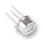


IRA-S200ST01A01
PIR (Pyroelectric Infrared) Sensor, 45 °, 4.6 mV, 2 V to 15 V, -40 °C to 70 °C, IRA-S Series
- Manufacturer: MURATA
- Product type: PIR Motion Sensors
- SVHC: No SVHC (04-Feb-2026)
- Lens Type: -
- Beam Angle: 45°
- Lens Colour: -
- Product Range: IRA-S Series
- Qualification: -
- Output Interface: -
- Detection Distance: -
- Supply Voltage Max: 15VDC
- Supply Voltage Min: 2VDC
- Detection Sensitivity: -
- No. of Detection Zones: -
- Current Consumption Typ: -
- Detection Area (Vertical): 45°
- Detection Area (Horizontal): 45°
| Delivery and price | |
|---|---|
| Units per pack | 500 |
| Price | 1.31 € |
| Current stock | 10+ |
| Lead time | 30 days |
**==> picture [452 x 607] intentionally omitted <==**
**----- Start of picture text -----**<br>
Messrs.: Specification No. JEGI33-0059<br>FARNELL ELEC COMPONENTS LTD<br>RoHS-Y<br>— Product Specification |<br>Issued Date: 5 Jun., 2023<br>Part Description: Pyroelectric infrared sensor<br>Customer Part No.: 4176134<br>MURATA Part No.: IRA-S200ST01A01<br>Acknowledgement of reception<br>We have received the attached specification<br> Date:<br>Company:<br>Dept.:<br>Representative Received by<br>Sales office Technical Dept.<br>Approved by<br>he<br> Y. KAWASHIMA<br>Issued by<br>Te NL. Ona<br>N. ARAI<br>Field Application Engineering Section 2<br>Product Engineering Department<br>Functional Devices Division<br>Murata Manufacturing Co., Ltd.<br>**----- End of picture text -----**<br>
(Y15) G0190
株式会社 村 田 製 作 所 Murata Manufacturing Co.,Ltd.
! お願い Note:
## 1
## ご使用に際しましては、貴社製品に実装された状態で必ず評価して下さい。
Please make sure that your product has been evaluated in view of your specifications with our product being mounted to your product.
## 2
## 当製品を当納入仕様書の記載内容を逸脱して使用しないで下さい。
You are requested not to use our product deviating from this product specification.
## 3
お手数ですが、当納入仕様書に貴社受領印を押印の上、1部を弊社へご返却下さい。 3ヶ月以内にご返却いただけない場合、又は、当納入仕様書をご返却いただく前にご注文をいた だいた場合は、当納入仕様書は、その時点で受領されたものとさせていただきます。
Please return one duplicate of this product specification to us with your signature to acknowledge your receipt. In case of no return within three months from submission date, or if we receive order before the duplicate is returned, this product specification will be deemed to have been received by you.
## 4
当社は、仕様書、図面その他の技術資料には、取引に関する契約事項を記載することは適切で はないものと存じております。従って、もし、貴社が作成されたこれら技術資料に、品質保証、P L、工業所有権等にかかる当社の責任の範囲に関する記載がある場合は、当該記載は無効とさ せていただきます。これらの事項につきましては、別途取引基本契約書等においてお申し越しい ただきたくお願いします。
We consider it not appropriate to include any terms and conditions with regard to the business transaction in the product specifications, drawings or other technical documents. Therefore, if your technical documents as above include such terms and conditions such as warranty clause, product liability clause, or intellectual property infringement liability clause, they will be deemed to be invalid.
株式会社 村 田 製 作 所 Murata Manufacturing Co.,Ltd.
Specification No. JEGI33-0059 P.1/15
焦電型赤外線センサ IRA-S200ST01A01 製品仕様書 Pyroelectric infrared sensor Product Specification
## 1. 適用範囲 Scope
この製品仕様書は、人感赤外線検知に使用されるデュアルタイプ焦電型赤外線センサ
IRA-S200ST01A01 について規定します。この用途以外にご使用の場合には事前に当社へご連絡下さい。 解釈により疑義が生じた場合には、和文の記載内容を優先します。
This product specification is applied to a dual element type pyroelectric infrared sensor IRA-S200ST01A01 used to detect infrared ray. Please contact us when using this product for any other applications than described in the above.
Japanese description has precedence of English one when question arises regarding interpretation.
|1-1|1-1適用用途 Specific Applications|
|---|---|
||セキュリティ機器<br>Security equipment<br>ディテクタなどの侵入検知、かつ、その機能が人命及び財産の保護<br>に直接的にかかわらない機器<br>Products that can be used in security equipment such as intrusion<br>detection, and whose functions are not directly related to the<br>protection of human life and property.<br>民生機器<br>Consumer equipment<br>家電機器・AV機器・通信機器・情報機器・事務機器・家庭用ロボット<br>機器といった民生機器、かつ、その機能が人命及び財産の保護に直<br>接的にかかわらない機器<br>Products that can be used in consumer equipment such as home<br>appliances, audio/visual equipment, communication equipment,<br>information equipment, office equipment, and household robotics,<br>and whose functions are not directly related to the protection of<br>human life and property.<br>~~—~~|
|1-2|1-2適用外用途Unsuitable Applications|
||以下の用途及び当製品仕様書の「用途の限定」に書かれている用途|
||The following applications and the showing at section 8 listed in “Limitation of applications” in|
||this product specification.|
||自動車機器<br>Automotive equipment<br>自動車及び、自動2輪、電動バイク、電動自転車を含むモビリティ用<br>途全般<br>Products that can be used for all Mobility applications including<br>automobiles, motorcycles, electric motorcycles, and electric<br>bicycles.<br>医療機器<br>Medical equipment<br>家庭用医療機器を含めたヘルスケア用途全般<br>Products that can be used for all healthcare applications,<br>including home medical equipment.<br>産業機器<br>Industrial equipment<br>基地局・製造機器・工業用ロボット機器・計測機器といった産業機器<br>Products that can be used in industrial equipment such as base<br>stations, manufacturing equipment, industrial robotics equipment,<br>and measurement equipment.<br>~~oe~~|
Rev.6
株式会社 村 田 製 作 所 Murata Manufacturing Co.,Ltd.
Specification No. JEGI33-0059 P.2/15 ~~ne~~
## 2. 品番 Part Number
IRA-S200ST01A01
## 3. 製品の形状・寸法および構造 Product figures / dimensions
- 3-1 形状・寸法 Figure / dimensions
**==> picture [264 x 332] intentionally omitted <==**
**----- Start of picture text -----**<br>
Y<br>B C1 D<br>X<br>1. @<br>タブ / Tab<br>A 光学フィルタ/ Optical Filter<br>C2<br>Top view<br>焦電素子/ Pyro-Element<br>Z<br>E F<br>底面/Base<br>L. X — G H<br>YT dg<br>Side view<br>I<br>J<br>(45deg.)<br>X<br>1 2<br>Y 3<br>r . an :<br>Bottom view<br>図1. 形状・寸法<br>Fig.1 Figure / dimensions<br>**----- End of picture text -----**<br>
|Symbol|Dimension<br>[mm]|
|---|---|
|A|4.7±0.1|
|B|3.7±0.1|
|C1|8.00.1|
|C2|8.20.1|
|D|9.20.2|
|E|3.50.2|
|F|4.70.2|
|G|0.450.05|
|H|13.52|
|I|5.080.15|
|J|1.50.1|
- 端子はNiメッキです Nickel-plated on terminal
- C1およびC2は底面から1.2mmの位置で の寸法とします C1 and C2 are specified on 1.2mm from base
- I は根元における寸法とします I is specified on base
Rev.6
株式会社 村 田 製 作 所 Murata Manufacturing Co.,Ltd.
Specification No. JEGI33-0059 P.3/15
3-2 受光部の配置および寸法(参考値) Dimension of infrared ray receiving electrode (For reference)
**==> picture [182 x 126] intentionally omitted <==**
**----- Start of picture text -----**<br>
受光部A 受光部B<br>(2.0)<br>©<br>(1.0) (1.0) (1.0) Unit :mm<br>Top view<br>**----- End of picture text -----**<br>
## 図 2. 受光部寸法
Fig.2 Dimension of infrared ray receiving electrode
## 3-3 内部回路構成 Internal circuit diagram
**==> picture [33 x 62] intentionally omitted <==**
**----- Start of picture text -----**<br>
Drain<br>Source<br>GND<br>**----- End of picture text -----**<br>
## 図3. 内部回路構成
Fig.3 Internal circuit diagram
- 3-4 製品本体への表示 Mark on product body 製品側面に印字します。 It has a marking on a side of the sensor.
D11XXXX D11 : 製品コード Model code XXXXXX : 内部管理番号 Internal control number ~~TT~~ 図 4. 印字 Fig.4 Marking
Rev.6
株式会社 村 田 製 作 所 Murata Manufacturing Co.,Ltd.
Specification No. JEGI33-0059 P.4/15
4. 基本動作条件(定格)および性能 Basic (rated) operation conditions and performances 4-1 基本動作条件(定格) Basic (rated) operation conditions
|項目<br>Content|基本動作条件(定格)<br>Basic (rated)<br>operation conditions|注記<br>Notes|
|---|---|---|
|電源電圧<br>Supply Voltage|2.0 to 15.0 VDC<br>(With circuit condition<br>shown in Fig.7)|電源電圧とは、Drain端子-GND端子間の電位差です。<br>Supply Voltage means the difference of electrical<br>potential between Drain terminal and Ground<br>terminal,|
|使用温度範囲<br>Operating<br>Temperature<br>range|-40 to 70C||
|保存温度範囲<br>Storage<br>Temperature<br>range|-40 to 85C||
4-2 性能 Performances 指定なき場合は25℃3℃とします。(Unless otherwise noted 25C3℃) Unit Symbol Min. Typ. Max. Test condition 出力電圧 RA mV 3.6 (4.6) - Refer to (Note 1) Responsivity RB 出力電圧バランス % - - - 10 Refer to (Note 1) Balance of Responsivity ホワイトノイズ mVpp Wn - - 150 Refer to (Note 2) White Noise ソース電圧 V Vs 0.2 - 1.5 Refer to (Note 3) ~~SSS~~ Source Voltage[at 25][][C ]
Rev.6
株式会社 村 田 製 作 所 Murata Manufacturing Co.,Ltd.
Specification No. JEGI33-0059 P.5/15
(Note 1) 出力電圧および出力電圧バランス Responsivity / Balance of Responsivity
- ・ ・
- RA RBを下記と定義します。RA RB are defined as below.
- RA : 受光部Aの出力電圧 Responsivity of Infrared ray receiving electrode A
- RB : 受光部Bの出力電圧 Responsivity of Infrared ray receiving electrode B
・ 図5の測定器構成において、センサに図6に示す目隠しを行い、受光部A Bそれぞれについて ・ ロックインアンプで1Hz成分の実効値を測定しています。測定したRA RBの出力電圧値から、下記 算出式に従って出力電圧バランスを算出します。
Effective value of signal output shall be measured using Lock-In-Amp with following system shown in Fig.5 and with the occluded sensor as shown in Fig.6. Balance of Responsivity shall be calculated based on formula below using measured RA and RB value.
出力電圧バランス/Balance of Responsivity(%) = | ( RA-RB ) / ( RA+RB) | 100
**==> picture [431 x 299] intentionally omitted <==**
**----- Start of picture text -----**<br>
ロックインアンプ<br>Lock-in Amp. (NF LI5640) 1Hz<br>140mm<br>+5V<br>φ10mm<br>1 22uF<br>黒体炉<br>Black body<br>500K 2<br>a t as 3 47kΩ aa オシロスコープ<br>Oscilloscope<br>メカニカルチョッパー1Hz 赤外線センサ<br>Mechanical Chopper Infrared Sensor<br>図5 出力電圧測定システム<br>Fig.5 Test system of Responsivity<br>側半分を覆う センサのRA側半分を覆う<br>B side) side) Occluding half of sensor (RA side)<br>RA測定時 RB測定時<br>Measuring RA Measuring RB<br>**----- End of picture text -----**<br>
センサのRB側半分を覆う Occluding half of sensor (RB side) side)
図6 出力電圧測定時のセンサ目隠し位置
Fig.6 Position of occluding sensor when measuring Responsivity
Rev.6
株式会社 村 田 製 作 所 Murata Manufacturing Co.,Ltd.
Specification No. JEGI33-0059 P.6/15
(Note 2) ホワイトノイズ White Noise 測定条件 Conditions for measurement ・使用回路 : 図7に示す測定回路を使用します。 Test circuit : Shown in Fig.7. ・測定点 : 図7測定回路図中 OUT端子 GND端子間を測定します。 Measuring Point : Across OUT and GND as shown in Fig.7. ・測定環境 : シールドボックス内、暗視野の状態で測定します。 Environment : In the electrically and optically shielded box.
図7 ホワイトノイズ測定回路
Fig.7 Test circuit for White Noise
## (Note 3) ソース電圧 Source Voltage
測定条件 Conditions for measurement
・使用回路 : 図8に示す測定回路を使用します。 Test circuit : Shown in Fig.8. ・測定点 : 図8測定回路図中 OUT端子 GND端子間を測定します。 Measuring Point : Across OUT and GND as shown in Fig.8. ・測定環境 : シールドボックス内、暗視野の状態で測定します。 Environment : In the electrically and optically shielded box.
図8.ソース電圧測定回路 Fig.8 Test circuit for Source Voltage
Rev.6
株式会社 村 田 製 作 所 Murata Manufacturing Co.,Ltd.
Specification No. JEGI33-0059 P.7/15 ~~Oe~~
(Note 4) 標準視野角(参考値) Field of View (For reference)
- 標準視野角とは、受光部AとBのいずれも受光部全体が見える角度の設計値です。
- Field of View means the designed value of angle that both of infrared receiving electrode A and B
- can be visible.
**==> picture [47 x 88] intentionally omitted <==**
**----- Start of picture text -----**<br>
(45deg.)<br>(45deg.)<br>**----- End of picture text -----**<br>
**==> picture [90 x 25] intentionally omitted <==**
**----- Start of picture text -----**<br>
図9 標準視野角<br>Fig.9 Field of View<br>**----- End of picture text -----**<br>
(Note 5) 光学フィルタ(参考) Optical Filter (For reference) 透過率 Transmittance : 図10に例を示します See the graph shown in Fig.10. 基板厚さ Thickness : 0.5mm
**==> picture [286 x 169] intentionally omitted <==**
**----- Start of picture text -----**<br>
Transmittance of Optical Filter<br>100<br>80 fy<br>60<br>| | |<br>ee<br>40<br>20<br>fF | | ft<br>J | | | |<br>0<br>4 5 6 7 8 9 10<br>波長 Wave length [μm]<br>[%]<br>Transmittance<br>透過率<br>**----- End of picture text -----**<br>
図10. 赤外線透過率(例)
Fig.10 Transmittance of Optical Filter (example)
Rev.6
株式会社 村 田 製 作 所 Murata Manufacturing Co.,Ltd.
Specification No. JEGI33-0059 P.8/15
## 5. 耐環境性能 Environmental resistance performance
各試験後、4節に記載の方法で表1記載項目を測定します。
After each test, contents stated in table 1 shall be measured following method stated in chapter 4.
|試験項目|試験条件|判定基準|判定基準|
|---|---|---|---|
|Test item|Test item<br>Test condition|Pass/Fail criteria||
|高温放置試験|周囲温度100C±2C、500時間経過後、常温にて3時間 放置後|表1の判定基準に従||
|High temperature<br>測定します。||います。||
|test|After being placed at +100C +/-2C for 500hours and then|Criteria is described||
||placed at ambient condition for 3 hours, test specimens shall|in table 1.||
||be measured.|||
|低温放置試験|周囲温度-40C±2C、500時間経過後、常温にて3時間放置後|||
|Low temperature<br>測定します。||||
|test|After being placed at -40C +/-2C for 500hours and then|||
||placed at ambient condition for 3 hours, test specimens shall|||
||be measured.|||
|高温湿中放置試験<br>周囲温度60C±2C、湿度93%RH +2/-3%RHで500時間経過||||
|Humidity test|後、常温にて3時間 放置後測定します。|||
||After being placed at 60C +/-2C and 93%RH +2/-3%RH for|||
||500hours and then placed at ambient condition for 3 hours, test|||
||specimens shall be measured.|||
|気槽式|-25C±2C、30min →常温、30min → 55C±2C、30minを1サ|||
|熱サイクル試験<br>イクルとして、20回繰り返します。||||
|Air heat cycle test<br>その後、常温にて3時間 放置後測定します。||||
||After being placed 20 times of the following cycle and then at|||
||ambient condition for 3 hours, test specimens shall be|||
||measured.|||
||Cycle condition : -25C±2C, 30min.Room temp. 30min.|||
||55C±2C, 30min.Room temp|||
||表1測定項目と判定基準|||
|Table 1. Measuring item and each Pass/Fail criteria<br>測定項目<br>Measuring item<br>判定基準<br>Pass/Fail criteria<br>出力電圧<br>Responsivity<br>初期値に対して変化率20%以内です。<br>Within ±20% shift from initial value<br>ノイズ<br>White Noise<br>Max. 250mVpp<br>ソース電圧<br>Source Voltage<br>25℃において、0.2V ~ 1.5Vの範囲内です。<br>0.2V to 1.5V at 25C<br> ~~===~~||||
||||Rev.6|
||株式会社 村 田 製 作 所 Murata Manufacturing Co.,Ltd.|||
Specification No. JEGI33-0059 P.9/15
## 6. 機械的性能 Physical performance
振動試験および衝撃試験後は、4節に記載の方法で表1記載項目を測定します。
After vibration test and shock test, contents stated in table 1 shall be measured following method stated in chapter 4.
|試験項目<br>Test item|試験条件<br>Test condition|判定基準<br>Pass/Fail criteria|
|---|---|---|
|振動試験<br>Vibration test|振動周波数10~55Hz、全振幅1.5mmの振動を、X,Y,Zの3方向<br>に各々60分加えます。<br>After applying vibration of amplitude of 1.5mm with 10 to 55Hz<br>bands to plus/minus of each of 3 perpendicular directions (x, y,<br>z) for an hour, test specimens shall be measured.|表1の判定基準に従<br>います。<br>Criteria is described<br>in table 1.|
|衝撃試験<br>Shock test|標準衝撃試験機にて、100G、作用時間6msの正弦半波の衝撃<br>を、3軸(X,Y,Z)の両方向に加えます。(1G=9.80665m/s2)<br>After being applied 3 impacts of 100G and 6ms in plus/minus<br>directions of 3 perpendicular axis (x, y, z), test specimens shall<br>be measured. (1G=9.80665m/s2)||
|はんだ付性<br>Solderability|ロジン系フラックスに浸した後、温度255±5Cのはんだ槽に、端<br>子根元2~2.5mmの位置まで5±0.5秒間浸します。<br>After immersing to the Rosin flux, immersing terminals to 2 to<br>2.5mm from base of PIR sensor in solder bath of 2555C for<br>5sec ±0.5sec|端子には75%以上<br>はんだが付着しま<br>す。a solder<br>attaches to a<br>terminal more than<br>75%.|
Rev.6
株式会社 村 田 製 作 所 Murata Manufacturing Co.,Ltd.
Specification No. JEGI33-0059 P.10/15 ~~ne~~
## 7. 包装 Packing
## 7-1 包装形態 Packing configuration
トムソン箱(箱サイズ:LWD(mm) 104x75x47)を使用して、図11のように100個/1箱で梱包します。 100 pieces sensors shall be packed in a unit box (box size: LWD(mm) 104x75x47) as shown in Fig.11.
**==> picture [216 x 113] intentionally omitted <==**
**----- Start of picture text -----**<br>
トムソン箱<br>Unit box<br>DODO<br>段ボール<br>waeneaeaw 導電性スポンジ Cardboard<br>atap<br>Conductive sponge<br>図11. 包装形態<br>Fig.11 Packing configuration<br>**----- End of picture text -----**<br>
## 7-2 包装ラベル、表示 Packing label and markings
図12のようにトムソン箱に表示します。
Indication shall be on the box as per Fig.12.
ただし日本国内向けは EIAJ C3 ラベルに準拠します。
For Japanese domestic cargo it is based on EIAJ C3 label.
* : Revised sign
## 図12. 包装ラベル、表示 (例) Fig.12 Packing label and markings (Example)
Rev.6
株式会社 村 田 製 作 所 Murata Manufacturing Co.,Ltd.
Specification No. JEGI33-0059 P.11/15
## 8. A 注意 Caution
8-1用途の限定 Limitation of Applications
当製品仕様書に記載の製品は、当社製品仕様書内で個別に記載の適用用途向けに設計・製造さ れたものであり、高度な性能・機能・品質・管理・安全性が要求される本注意書き末尾①から⑪までの 用途への適合性・性能発揮・品質等を保証するものではありませんので、当社製品仕様書記載の適 用用途に従ってご使用ください。
The products listed in the product specification(hereinafter the product(s) is called as the “Product(s)”) are designed and manufactured for applications specified in the product specification. (hereinafter called as the “Specific Application”).
We shall not warrant anything in connection with the Products including fitness, performance, adequateness, safety, or quality, in the case of applications listed in from (1) to (11) written at below, which may generally require high performance, function, quality, management of production or safety. Therefore, the Product shall be applied in compliance with the specific application.
万が一、当製品仕様書記載の適用用途以外の用途でご使用された場合、又は以下の①から⑪まで の用途でご使用された場合(別途当製品仕様書内に用途記載があるものは除く*)には、当社は当該使 用によって生じた不測の事故その他の損害に関する一切の責任を負いかねますのでご注意ください。
WE DISCLAIM ANY LOSS AND DAMAGES ARISING FROM OR IN CONNECTION WITH THE PRODUCTS INCLUDING BUT NOT LIMITED TO THE CASE SUCH LOSS AND DAMAGES CAUSED BY THE UNEXPECTED ACCIDENT, IN EVENT THAT (i) THE PRODUCT IS APPLIED FOR THE PURPOSE WHICH IS NOT SPECIFIED AS THE SPECIFIC APPLICATION FOR THE PRODUCT, AND/OR (ii) THE PRODUCT IS APPLIED FOR ANY FOLLOWING APPLICATION PURPOSES FROM (1) TO (11) (EXCEPT THAT SUCH APPLICATION PURPOSE IS UNAMBIGUOUSLY SPECIFIED AS SPECIFIC APPLICATION FOR THE PRODUCT IN OUR CATALOG SPECIFICATION FORMS, DATASHEETS, OR OTHER DOCUMENTS OFFICIALLY ISSUED BY US*).
①航空機器 ②宇宙機器 ③海底機器 ④発電所制御機器 ⑤医療機器 ⑥輸送機器 ⑦交通用信号機器 ⑧防災/防犯機器 ⑨産業用情報処理機器 ⑩燃焼/爆発制御機器 ⑪その他上記機器と同等の機器
(1) Aircraft equipment
(2) Aerospace equipment
- (3) Undersea equipment
- (4) Power plant control equipment
- (5) Medical equipment
- (6) Transportation equipment
- (7) Traffic control equipment
- (8) Disaster prevention/security equipment
- (9) Industrial data-processing equipment
- (10) Combustion/explosion control equipment
(11) Equipment with complexity and/or required reliability equivalent to the applications listed in the above.
Rev.6
株式会社 村 田 製 作 所 Murata Manufacturing Co.,Ltd.
Specification No. JEGI33-0059 P.12/15
当製品仕様書に記載の適用用途以外の用途に対応した製品については、お客様とお取引のある当 社営業窓口・代理店・商社、またはお問い合わせフォーム( https://www.murata.com/contactform ) までお問い合わせください。
For exploring information of the Products which will be compatible with the particular purpose other than those specified in the product specification, please contact our sales offices, distribution agents, or trading companies with which you make a deal, or via our web contact form. Contact form: https://www.murata.com/contactform
*製品によっては、①から⑪までの用途向けに設計・製造される場合があり、それらは当社カタログ、 仕様書、データシート等に個別で適用用途を記載しております。
*We may design and manufacture particular Products for applications listed in (1) to (11). Provided that, in such case we shall unambiguously specify such Specific Application in the product specification without any exception. Therefore, any other documents and/or performances, whether exist or non-exist, shall not be deemed as the evidence to imply that we accept the applications listed in (1) to (11).
## 8-2 フェールセーフ機能の付加 Addition of a Fail-safe function
当製品に万が一異常や不具合が生じた場合でも、二次災害防止のために完成品に適切なフェール セーフ機能を必ず付加して下さい。
Be sure to add an appropriate fail-safe function to your finished product to prevent secondary damage in the unlikely event of an abnormality function or malfunction in our product.
Rev.6
株式会社 村 田 製 作 所 Murata Manufacturing Co.,Ltd.
Specification No. JEGI33-0059 P.13/15
## 9. 使用上の注意 Caution for use
- 9-1 設計時 Notice in design
- 1) 屋外で使用される場合や、防水性を要求されるような環境で使用される場合は、適切な光学フィル タの設置、防水構造の採用、および、結露対策等を十分施して下さい。誤動作や、回路ショート等 の原因となります。
- In the case of outdoor use, suitable Optical Filter and water and humidity proof structure should be applied.
- 2) 電源には安定化電源を使用して下さい。
To prevent failure or malfunction, Please use a stabilized power supply.
- 3) 誤動作や動作しないことが予想されますので、下記のような状態ではご使用しないで下さい。 Please avoid using the sensor in the following conditions because it may cause failure or malfunction ;
- a) 液体中(水、有機溶媒等)や腐蝕性ガス(亜硫酸ガス、塩素ガス、窒素酸化ガス等)および、 潮風中での使用。
- In such a fluid as water, alcohol etc. corrosive gas (SO2, Cl2, NOX etc.) or sea breeze.
- b) 高湿下での連続使用。
- In high humidity.
- c) 太陽光、自動車のヘッドライト等の直射を受ける場所での使用。
- In a place exposed directly to sunlight or headlight of automobile.
- d) 急激な温度変化がある場所での使用。
- In a place exposed to rapid ambient temperature change.
- e) 温風ヒーター、エアコン等の送風を直接受ける場所での使用。
- In a place exposed directly to blow from air-conditioner or heater.
- f) 強い振動がある場所での使用。
- In a place exposed to strong vibration.
- g) 強い電磁波がある場所での使用。
- In a place exposed to strong electromagnetic field.
- h) 当センサの検知エリア内に赤外線を透さない障害物(ガラスや壁等)がある場所での使用。 In such a place where infrared ray is shaded.
- i) 帯電、静電気が発生する場所での使用。
In such a place are charge field and static electricity field.
- ~
- j) その他、上記a) i)項に準じる場所での使用。
- In any other place similar to the above (a) through (i).
## 9-2 保管および使用時 Notice in handling and storage
- 1) 当センサの光学フィルタを汚したり、傷をつけないで下さい。
- Optical Filter of sensor should not be scratched or soiled.
- 2) センサ本体、および、端子部に強い衝撃を与えないで下さい。 Strong shock should be avoided.
- 3) 静電気や、電磁波の環境下では誤動作する可能性があります。 十分ご評価の上、ご使用下さい。 It may malfunction under electrostatics and electromagnetic field. Please use it after enough evaluating.
- 4) 静電気や、強い電磁波等のある場所で保管しないで下さい。 Electrostatics and strong electromagnetic field should be avoided.
- 5) 端子を、導電性スポンジから外した状態で保管しないで下さい。 Sensor should be kept on conductive sponge
Rev.6
株式会社 村 田 製 作 所 Murata Manufacturing Co.,Ltd.
Specification No. JEGI33-0059 P.14/15
- 6) 高温、多湿、塵埃の多い場所、液体中(水、有機溶媒等)、腐蝕性ガス(亜硫酸ガス、塩素ガス、窒 素酸化物ガス等)および、潮風の存在する場所で保管しないで下さい。 High temperature, high humidity, fluid as water or alcohol etc., corrosive gas ( SO2, Cl2, NOX etc.) and sea breeze should be avoided.
- 7) 保管環境は、周囲温度-10~40℃、相対湿度15~85%とし、納入後6ヶ月以内にご使用下さい。 また、6ヶ月以上を経過したものはご使用の前にはんだ付け性を確認して下さい。 Store the products where the temperature and relative humidity do not exceed -10 to 40 degrees centigrade, and 15 to 85%RH. Use the products within 6 months after receiving. Check the terminal solderability before use if the product has been stored for more than 6 months.
## 9-3 実装時 Notice in mounting
- 1) 端子のはんだ付けは、こて先はんだで行って下さい。
Please perform the soldering of the terminal with an iron point solder.
- 2) 端子のはんだ付けは、できるだけすばやく行って下さい。 具体的には下記の範囲で行って下さい。
Please mount the soldering of the terminal as quick as possible. Specifically, please go in the range of follows.
|Please perform the soldering of the terminal with an iron point solder.<br>端子のはんだ付けは、できるだけすばやく行って下さい。<br>具体的には下記の範囲で行って下さい。<br>Please mount the soldering of the terminal as quick as possible. Specifically, please go in the<br>range of follows.lows.|Please perform the soldering of the terminal with an iron point solder.<br>端子のはんだ付けは、できるだけすばやく行って下さい。<br>具体的には下記の範囲で行って下さい。<br>Please mount the soldering of the terminal as quick as possible. Specifically, please go in the<br>range of follows.lows.|
|---|---|
|はんだのこて先温度:350℃<br>ironpoint temperature:350 degree C||
|端子根元からの長さ<br>Terminal length from stem|時間<br>time|
|1~3mm<br>1 to 3mm|1ヶ所につき3秒以内<br>Less than 3sec by a terminal|
|3mm以上<br>Over 3mm|1ヶ所につき10秒以内<br>Less than 10sec by a terminal|
- 3) フラックスは、塩素含有率 0.2wt%以下の水溶性のものをご使用下さい。
- Please use the flux which has a water-soluble thing less than chlorine content 0.2% by weight.
- 4) はんだ付け後のフラックスは、完全に除去して下さい。不十分な場合は、誤動作等の原因となりま す。
Please completely remove the flux after the soldering. When you are insufficient, it causes the malfunction.
※当製品は、一度でも限度を超えた高温状態になると、特性を失い機能しなくなります。 当製品仕様書記載の条件を越えた温度が加わらないように実装して下さい。
- ※Please follow soldering conditions described in the specification.
- This product can permanently stop operating if the piezoelectric (pyroelectric) characteristic is decreased due to excessive heating.
Rev.6
株式会社 村 田 製 作 所 Murata Manufacturing Co.,Ltd.
Specification No. JEGI33-0059 P.15/15
## 10. A お願い Note
- 1) ご使用に際しては、貴社製品に実装された状態で必ず評価して下さい。
- Please make sure that your product has been evaluated in view of your specifications with our product being mounted to your product.
- 2) 当製品を当製品仕様書の記載内容を逸脱して使用しないで下さい。
You are requested not to use our product deviating from this product specification.
Rev.6
株式会社 村 田 製 作 所 Murata Manufacturing Co.,Ltd.
Updated at June 1, 2026
Established in Kyoto in 1944, Murata has grown into a global leader in the design and manufacture of advanced electronic components, specializing in ceramic passive components, wireless connectivity modules, and power conversion technologies. Renowned for its foundational work in materials science and process innovation, Murata delivers solutions that drive the evolution of modern electronics across telecommunications, mobility, industrial, and healthcare applications. This extensive portfolio is anchored by a broad selection of high-performance passive components, heavily focused on inductive solutions. Engineers can choose from hundreds of specialized RF inductors and power inductors engineered for exceptional reliability, efficiency, and miniaturization. The range also features robust EMC and RFI suppression solutions, highlighted by industry-leading common mode chokes and power line filters designed to ensure signal integrity and strict regulatory compliance in demanding circuit environments. Beyond inductive and filtering components, the offering encompasses a comprehensive array of critical circuit protection, timing, and power devices. Murata's precision NTC and PTC thermistors provide essential temperature sensing and thermal management, while its robust lineup of ceramic resonators and quartz crystals ensures highly accurate frequency control. Supported by premium non-rechargeable batteries, polymer capacitors, and advanced sensing transducers, Murata equips designers with the versatile building blocks required for next-generation technological development.
About Novapart
Novapart is a B2B electronic component broker specialising in stock shortages and cost reduction. We source hard-to-find parts and identify compliant alternatives across a catalogue of 410,000+ components from 500+ manufacturers.
Learn more →Stock Shortage Specialist
When a component is unavailable, discontinued or has an unacceptable lead time, we tap into our network of vetted European and Asian distributors to source what you need — without compromising on quality or traceability.
Request a quote →Compliant Alternatives
We identify pin-to-pin, electrically equivalent substitutes that meet the same certifications (RoHS, AEC-Q100, REACH) as your original specification — validated against datasheets, not just part numbers. Often at a lower cost.
BOM Analysis service →