
Image not available
Illustrative purposes only

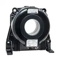
IN 2000-S
Current Sensor, High Precision, Closed Loop Flux Gate, 2kA, ±15V, Wide Temperature Range, IN Series
⚠️ Reference pricing provided. In case of supply shortages, we will connect you with our trusted procurement partners to ensure your project's continuity.
- Manufacturer: LEM
- Product type: Current Sensors
- SVHC: No SVHC (25-Jun-2025)
- Accuracy %: 0.0014%
- Product Range: IN Series
- Response Time: 1µs
- Sensor Output Type: Current
- Supply Voltage DC Max: 15.75V
- Supply Voltage DC Min: 14.25V
- Current Measuring Range AC: 2kA
- Current Measuring Range DC: -2kA to 2kA
| Delivery and price | |
|---|---|
| Units per pack | 50 |
| Price | 4865.46 € |
| Current stock | 10+ |
| Lead time | 30 days |
Datasheet

## **Current Transducer IN 2000-S**

## _I_ **= 2000 A** P N

For the electronic measurement of current: DC, AC, pulsed..., with galvanic separation between the primary and the secondary circuit.

## **Features**

- ●Closed loop (compensated) current transducer using an extremely accurate zero flux detector

- ●Electrostatic shield between primary and secondary circuit

- ●9-pin D-Sub male secondary connector

- ●Status signal to indicate the transducer state

- ●LED indicator confirms normal operation

- ●Metal housing to improve immunity to EMC & power dissipation

- ●Operating temperature −40 °C to 85 °C.

## **Applications**

- ●Feed back element in high performance gradient amplifiers for MRI

- ●Feedback element in high-precision, high-stability power supplies

- ●Calibration unit

- ●Energy measurement

- ●Medical equipment.

## **Standards**

- ●EN 61000-6-2: 2005

## **Advantages**

- ●Very high accuracy

- ●Excellent linearity

- ●Extremely low temperature drift

- ●Wide frequency bandwidth

- ●High immunity to external fields

- ●No insertion losses

- ●EN 61000-6-3: 2007

- ●EN 61010-1: 2010.

## **Application Domain**

   - ●Industrial

   - ●Laboratory

   - ●Medical.

- ●Very low noise on output signal

- ●Low noise feedback to primary conductor.

N° 97.N6.69.000.0

Page 1/9

LEM reserves the right to carry out modifications on its transducers, in order to improve them, without prior notice

26May2020/Version 2

www.lem.com

**IN 2000-S**

## **Insulation coordination**

**==> picture [511 x 24] intentionally omitted <==**

**----- Start of picture text -----**<br>
Parameter Symbol Unit Value Comment<br>**----- End of picture text -----**<br>


||**Symbol**|**Unit**|**Value**|**Value**|
|---|---|---|---|---|
||||||
|Rated insulation RMS voltage, basic insulation|_U_Nm|V|1000|IEC 61010-1 conditions<br>- over voltage cat III<br>- pollution degree 2|
|Rated insulation RMS voltage, reinforced insulation|||1000|IEC 61010-1 conditions<br>- over voltage cat III<br>- pollution degree 2|
|RMS voltage for AC insulation test, 50 Hz, 1 min|_U_d|kV|6|Between primary and<br>secondary + shield|
|||V DC|100|Between secondary and test<br>winding|
|Impulse withstand voltage 1.2/50 μs|_U_Ni|kV|12.8||
|Clearance (pri. - sec.)|_d_CI|mm|21|Shortest distance through air|
|Creepage distance (pri. - sec.)|_d_Cp|mm|22|Shortest path along device<br>body|
|Comparative tracking index|_CTI_||250||


## **Environmental and mechanical characteristics**

|**Parameter**|**Symbol**|**Unit**|**Min**|**Typ**|**Max**|**Comment**|
|---|---|---|---|---|---|---|
|Ambient operating temperature|_T_A|°C|−40||85||
|Ambient storage temperature|_T_A st|°C|−40||85||
|Relative humidity|_RH_|%|20||80||
|Dimensions||||||See drawing in<br>page 8|
|Mass|_m_|kg||4.2|||


Page 2/9 www.lem.com

LEM reserves the right to carry out modifications on its transducers, in order to improve them, without prior notice

26May2020/Version 2

**IN 2000-S**

## **Electrical data**

At _T_ A = 25 °C, ± _U_ C  = ±15 V, unless otherwise noted.

Lines with a * in the comment column apply over the −40 … 85 °C ambient temperature range.

**==> picture [512 x 22] intentionally omitted <==**

**----- Start of picture text -----**<br>
Parameter Symbol Unit Min Typ Max Comment<br>**----- End of picture text -----**<br>


|**Parameter**|**Symbol**|**Unit**|**Min**|**Typ**|**Max**||**Comment**|
|---|---|---|---|---|---|---|---|
|||||||||
|Primary nominal DC current (continuous)|_I_P N DC|A|−2000||2000|*||
|Primary nominal RMS current|_I_P N|A|||2000|*||
|Primary current, measuring range|_I_P M|A|−3000||3000|*||
|Measuring resistance|_R_M|Ω|0||1||See curve page 5|
|Secondary nominal RMS current|_I_S N|A|−1||1|*||
|Number of secondary turns|_N_S|||2000||||
|Resistance of secondary winding|_R_S|Ω||4||||
|Maximum withstand primary peak current1)|_Î_P max|kA|−10||10||@ pulse of 100 ms|
|Supply voltage positive|_+U_C|V|14.25|15|15.75|||
|Supply voltage negative|_−U_C|V|−15.75|−15|−14.25|||
|Current consumption positive|_+I_C|mA|180|200|225||Add_I_Sfor total<br>current consumption|
|Current consumption negative|_−I_C||80|89|100|||
|Output RMS noise current 0 … 10 Hz2)|_I_no|ppm||0.1||||
|Output RMS noise current 0 … 10 kHz2)||||4||||
|Output RMS noise current 0 … 160 kHz2)||||20||||
|Output peak-to-peak noise current2)|_I_no pp|ppm||50||||
|Electrical ofset current + self magnetization<br>+ efect of earth magnetic feld2)|_I_O E|ppm|−10||10|*||
|Temperature coefcient of_I_O E @_I_P= 0 A|_TCI_O E|ppm/K||0.1||||
|Ofset stability2)||ppm/month|−1||1|||
|Linearity error2)|_ε_L|ppm||1|2|||
|||||2|3|*||
|Delay time to 90 % of the fnal output value<br>for_I_P N DCstep|_t_D 90|µs|||1||d_i_/d_t_of 100 A/μs|
|Frequency bandwidth (±1 dB)|_BW_|kHz||130|||Small-signal<br>bandwidth, 0.5 %<br>of_I_P N|
|Frequency bandwidth (±3 dB)|_BW_|kHz||140||||
|Test current|_I_T|A|||1|||
|Number of turns (test winding)|_N_T|||200||||
|Start-up time|_t_start|s|2|5|15|||


Notes: 1) Single pulse only, not AC. The transducer may require a few seconds to return to

normal operation when autoreset system is running

2) All ppm figures refer to full-scale which corresponds to a secondary nominal RMS current of 1 A.

Page 3/9 www.lem.com

LEM reserves the right to carry out modifications on its transducers, in order to improve them, without prior notice

26May2020/Version 2

**IN 2000-S**

## **Overload protection - Electrical specification - Status**

The overload occurs when the primary current _I_ P exceeds a trip level such that the fluxgate detector becomes completely saturated and, consequently, the transducer will switch from normal operation to overload mode.

This trip level is guaranteed to be greater than _I_ P M and its actual value depends on operating conditions such as temperature and measuring resistance.

When this happens, the transducer will automatically begin to sweep in order to lock on the primary current again.

The overload conditions will be:

- ●The secondary current _I_ S generated is a low frequency signal.

- ●The signal normal operation status (between pin 3 and 8 of the D-sub connector) switches to V+. In other words, the output transistor is switched off (i.e., no current from collector to emitter). See the status port wiring below.

- ●The green LED indicator (normal operation status) turns off.

The measuring can resume when the primary current returns in the measuring range between − _I_ P N and + _I_ P N. Then the signal normal operation status switches to GND and the green LED indicator (normal operation status) is again lit.

## **Status/Interlock port wiring**

**==> picture [332 x 342] intentionally omitted <==**

**----- Start of picture text -----**<br>
U +<br>I C E max : 30 mA<br>I C E min  :   2 mA<br>The optocoupler is driven as follows:<br>ON   : Transducer is OK<br>OFF : Transducer is not OK  U+ (V) − 0.4 V<br>U+ (V) −0.4 V<br>I C E max : 30 mA<br>I C E min  :   2 mA<br>The optocoupler is driven as follows:<br>ON   : Transducer is OK<br>OFF : Transducer is not OK<br>U+ (V) −0.4 V<br>U+ (V) −0.4 V<br>Normal operation  : 4 ... +24V<br>status is : Active Low DC<br>Power<br>Supply<br>R<br>D-Sub9<br>Pin<br>8 Normal operation<br>Collector status<br>D-Sub9<br>Pin<br>Emitter 3 R  min (kΩ) =  30 mA<br>R  max (kΩ) =  2 mA<br>TRANSDUCER USER SIDE<br>Normal operation  U+ : 4 ... +24V<br>status is : Active High  D-Sub9 Power DC<br>Pin Supply<br>8<br>Collector<br>D-Sub9<br>Pin<br>Emitter<br>3 Normal operation<br>status<br>R R  min (kΩ) =  30 mA<br>R  max (kΩ) =  2 mA<br>TRANSDUCER USER SIDE<br>**----- End of picture text -----**<br>


The following table shows how the normal operation status acts as below:

**==> picture [512 x 22] intentionally omitted <==**

**----- Start of picture text -----**<br>
Status Value Description<br>**----- End of picture text -----**<br>


|**Status**|**Value**|**Description**|
|---|---|---|
||||
|Active Low|≈ 0.7 V|The transducer is OK (Normal operation)|
||_U+_|The transducer is not OK (Overload mode or supply fault)|
|Active High|_U+_|The transducer is OK (Normal operation)|
||≈ 0.7 V|The transducer is not OK (Overload mode or supply fault)|


Page 4/9

LEM reserves the right to carry out modifications on its transducers, in order to improve them, without prior notice

26May2020/Version 2

www.lem.com

**IN 2000-S**

The following table shows how the normal operation status acts as below:

|**Normal operation status**|**Description**|
|---|---|
|< 0.7 V|The transducer is OK (Normal operation)|
|_U+_|The transducer is not OK (Overload mode or supply fault)|


## **Maximum measuring resistor versus primary current and temperature**

## ± _U_ C  = ±14.25 V

**==> picture [366 x 558] intentionally omitted <==**

Page 5/9 www.lem.com

LEM reserves the right to carry out modifications on its transducers, in order to improve them, without prior notice

26May2020/Version 2

**IN 2000-S**

## **Power supply and load**

In order to reach the measuring range according to the maximum measuring resistor, be careful with the setup measurement when wires length are high. It means that:

- ●the wires resistance could be not negligible

- ●the voltage at the output of the DC power supply and the voltage at the transducer could be significantly different.

**==> picture [389 x 208] intentionally omitted <==**

**----- Start of picture text -----**<br>
ℓ<br>S<br>+  U C R W1 +  U C Transducer<br>0V<br>-  U 0VC RR W1W1 -  U C<br>R LOAD<br>Minimum ±  U C  -5% must be<br>seen by the transducer<br>DC power<br>supply<br>R W wires<br>resistance could<br>be not negligible<br>W2<br>R<br>OUTPUT OUTPUT RETURN<br>W2<br>R<br>**----- End of picture text -----**<br>


_R_ W wire resistance in Ω is:

ℓ _R_ W = ρ S

S: Cross section of wire in m[2 ] ℓ: Wire length in m ρ: Resistivity of material in Ω.m

## **Total measuring resistance is:**

_R_ M = _R_ L + 2 × _R_ W1 + 2 × _R_ W2

If _R_ W1 = _R_ W2 = _R_ WIRE then _R_ M = _R_ L + 4 × _R_ WIRE

Page 6/9 www.lem.com

LEM reserves the right to carry out modifications on its transducers, in order to improve them, without prior notice

26May2020/Version 2

**IN 2000-S**

## **Performance parameters definition**

The schematic used to measure all electrical parameters is shown below:

## **Linearity**

To measure linearity, the primary current (DC) is cycled from 0 to the maximum positive or negative difference between the _I_ P M, then to − _I_ P M and back to 0. The linearity error _ε_ L is measured points and the linear regression line, expressed in parts per million (ppm) of full-scale which corresponds to the maximum measured value.

## **Electrical offset**

## **Transducer simplified model**

The static model of the transducer at temperature _T_ A is:

The electrical offset current _I_ O E is the residual output current when the input current is zero.

The temperature variation _I_ O _T_ of the electrical offset current _I_ O E is the variation of the electrical offset from 25 °C to the considered temperature.

## **Delay times**

In which

**==> picture [62 x 11] intentionally omitted <==**

**==> picture [156 x 11] intentionally omitted <==**

The delay time respect to the primary are shown in the next figure. _t_ D 10 @ 10 % and the delay time _t_ D 90 @ 90 % with Both slightly depend on the primary current d _i_ /d _t_ . They are measured at nominal current.

Where,

**==> picture [148 x 10] intentionally omitted <==**

_I_ S : secondary current (A) _N_ P/ _N_ S : turns ratio (1: _N_ S) _I_ P : primary current (A) _I_ P M : primary current, measuring range (A) _T_ A : ambient operating temperature (°C) _I_ O E : electrical offset current (A) _I_ O _T_ : temperature variation of _I_ O E at _T_ A (A) _ε_ L : linearity error

**==> picture [158 x 115] intentionally omitted <==**

**----- Start of picture text -----**<br>
I<br>100 %<br>90 %<br>I P IS<br>t D 90<br>10 %<br>t D 10 t<br>**----- End of picture text -----**<br>


This is the absolute maximum error. As all errors are independent, a more realistic way to calculate the error would be to use the following formula:

**==> picture [66 x 39] intentionally omitted <==**

**----- Start of picture text -----**<br>
N<br>2<br>ε = ε<br>∑ 𝑖𝑖<br>𝑖𝑖  =1<br>**----- End of picture text -----**<br>


Page 7/9 www.lem.com

LEM reserves the right to carry out modifications on its transducers, in order to improve them, without prior notice

26May2020/Version 2

**IN 2000-S**

## **Safety**

This transducer must be used in limited-energy secondary circuits according to IEC 61010-1.

This transducer must be used in electric/electronic equipment with respect to applicable standards and safety requirements in accordance with the manufacturer’s operating instructions.

Caution, risk of electrical shock

When operating the transducer, certain parts of the module can carry hazardous voltage (e.g. primary busbar, power supply). Ignoring this warning can lead to injury and/or cause serious damage.

This transducer is a build-in device, whose conducting parts must be inaccessible after installation.

A protective housing or additional shield could be used. Main supply must be able to be disconnected.

## **Remark**

Installation of the transducer must be done unless otherwise specified on the datasheet, according to LEM Transducer Generic Mounting Rules. Please refer to LEM document N°ANE120504 available on our Web site: **Products/Product Documentation.**

Page 8/9

LEM reserves the right to carry out modifications on its transducers, in order to improve them, without prior notice

26May2020/Version 2

www.lem.com

**IN 2000-S**

## **Dimensions** (in mm)

**==> picture [62 x 10] intentionally omitted <==**

**----- Start of picture text -----**<br>
Connection<br>**----- End of picture text -----**<br>


## **Connection**

- ●Normal operation status (Pins 3 and 8) Normal operation means:

   - ±15 V (± _U_ C) present

   - zero detector is working

   - compensation current  ≤ _I_ P M DC

   - green LED indicator is lit.

## **Mechanical characteristics**

- ●General tolerance ±0.75 mm

- ●Transducer fastening - Horizontal mounting 4 holes ⌀ 7 mm and vertical with 2 slots gap along transducer

## **Remarks**

- _I_ S is positive when _I_ P flows in the direction of the arrow.

- ●We recommend that a shielded output cable and plug are used to ensure the maximum immunity against electrostatic fields.

- ●Temperature of the primary conductor should not exceed 100 °C.

- ●We recommend to fix the potential of the housing to the ground.

- ●Installation of the transducer must be done unless otherwise specified on the datasheet, according to LEM Transducer Generic Mounting Rules. Please refer to LEM document N°ANE120504 available on our Web site: **Products/Product Documentation.** i

4 × M6 steel screws

Recommended fastening torque 5.5 N ⋅ m ●Connection of secondary on D-SUB-9, UNC 4-40

- ●All mounting recommendations are given for a standard mounting. Screws with flat and spring washers.

Page 9/9 www.lem.com

LEM reserves the right to carry out modifications on its transducers, in order to improve them, without prior notice

26May2020/Version 2
Updated at June 10, 2026
About Novapart
Novapart is a B2B electronic component broker specialising in stock shortages and cost reduction. We source hard-to-find parts and identify compliant alternatives across a catalogue of 410,000+ components from 500+ manufacturers.
Learn more →Stock Shortage Specialist
When a component is unavailable, discontinued or has an unacceptable lead time, we tap into our network of vetted European and Asian distributors to source what you need — without compromising on quality or traceability.
Request a quote →Compliant Alternatives
We identify pin-to-pin, electrically equivalent substitutes that meet the same certifications (RoHS, AEC-Q100, REACH) as your original specification — validated against datasheets, not just part numbers. Often at a lower cost.
BOM Analysis service →