
Image not available
Illustrative purposes only

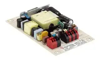
IDPV-25A-36
LED Driver, 25.2 W, 36 VDC, 700 mA, Constant Voltage, 90 V
⚠️ Reference pricing provided. In case of supply shortages, we will connect you with our trusted procurement partners to ensure your project's continuity.
- Manufacturer: MEAN WELL
- Product type: AC / DC LED Power Supplies
- SVHC: No SVHC (12-Jan-2017)
- Product Range: IDPV-25
- Output Current: 700mA
- LED Driver Mode: Constant Voltage
- Output Power Max: 25.2W
- Input Voltage Max: 295V
- Input Voltage Min: 90V
- Output Voltage Max: 36VDC
- Power Supply Applications: -
| Delivery and price | |
|---|---|
| Units per pack | 20 |
| Price | 14.61 € |
| Current stock | 10+ |
| Lead time | 30 days |
Datasheet

**- IDPV 25 series**

25W PWM Output LED Driver

**==> picture [13 x 11] intentionally omitted <==**

**----- Start of picture text -----**<br>
■<br>**----- End of picture text -----**<br>


**==> picture [121 x 29] intentionally omitted <==**

**----- Start of picture text -----**<br>
S&E<br>■<br>**----- End of picture text -----**<br>


**==> picture [13 x 11] intentionally omitted <==**

**----- Start of picture text -----**<br>
■<br>**----- End of picture text -----**<br>


~ the high ℃ ~+45 ℃

**==> picture [13 x 11] intentionally omitted <==**

**----- Start of picture text -----**<br>
■<br>**----- End of picture text -----**<br>


|«| A[2][in][1][dimming][and][Auxiliary] DC[output]

_File Name:IDPV-25-SPEC   2018-03-15_

**- IDPV 25 series**

25W PWM Output LED Driver

## **SPECIFICATION**

|**IDPV-25    -12**<br>**IDPV-25    -24**<br>**IDPV-25    -36**<br>**IDPV-25    -48**<br>**IDPV-25    -60**<br>**MODEL**<br>**OUTPUT**<br>**FREQUENCY RANGE**<br>**POWER FACTOR (Typ.)**<br>**EFFICIENCY (Typ.)**<br>**AC CURRENT (Typ.)**<br>**INPUT**<br>**INRUSH CURRENT(Typ.)**<br>**LEAKAGE CURRENT**<br>**SAFETY STANDARDS**<br>**WORKING HUMIDITY**<br>**STORAGE TEMP., HUMIDITY**<br>**TEMP. COEFFICIENT**<br>**VIBRATION**<br>**MTBF**<br>**DIMENSION**<br>**OTHERS**<br>**NOTE**<br>**PACKING**<br>**OVER CURRENT**<br>47 ~ 63Hz<br>105 ~ 120%<br>Protection type : Constant current limiting, recovers automatically after fault condition is removed<br>20 ~ 90% RH non-condensing<br>-40 ~ +80<br>, 10 ~ 95% RH<br>℃<br>±<br>℃<br>℃<br>0.03%/<br>(0 ~ 45<br>)<br>10 ~ 500Hz, 2G 10min./1cycle, period for  60min. each along X, Y, Z axes<br>**ENVIRONMENT**<br>**SAFETY &**<br>**EMC**<br>**PROTECTION**<br>**EMC IMMUNITY**<br>**EMC EMISSION**<br>**WITHSTAND VOLTAGE**<br>**ISOLATION RESISTANCE**<br>**TOTAL HARMONIC DISTORTION**<br>I/P-O/P:3.75KVAC<br>I/P-O/P:100M Ohms / 500VDC / 25<br>/ 70% RH<br>℃<br>±10%<br>0~100%<br>80%<br>81%<br>82%<br>83%<br>84%<br>0.4A / 115VAC       0.16A / 230VAC          0.13A / 277VAC<br><0.75mA / 277VAC<br>114.5*72.5*20mm (L*W*H)<br>0.145Kg;72pcs/11.44Kg/1.13CUFT<br>**SHORT CIRCUIT**<br>**DIMMING RANGE**<br>**DC VOLTAGE**<br>**CONSTANT CURRENT REGION**<br>**RATED POWER**<br>**SETUP TIME Note.3**<br>**VOLTAGE TOLERANCE**<br>**VOLTAGE RANGE Note.2**<br>1KHz (<br>20%)<br>±<br>500ms / 230VAC  1200ms/115VAC<br>12V<br>24V<br>36V<br>48V<br>60V<br>1.8A<br>1.05A<br>0.7A<br>0.52A<br>21.6W<br>25.2W<br>25.2W<br>24.96W<br>0.42A<br>25.2W<br>**PWM FREQUENCY (Typ.)**<br>**AUXILIARY DC OUTPUT Note.4**<br>Nominal 12V(deviation 11.4~12.6)@50mA for A-Type only<br>(Please refer to "STATIC CHARACTERISTIC" section)<br>90 ~ 295VAC          127 ~ 417VDC<br>PF>0.95/115VAC, PF>0.92/230VAC, PF>0.9/277VAC@full load<br>(Please refer to "POWER FACTOR (PF) CHARACTERISTIC" section)<br>THD< 20%(@load 70%/115VAC,230VAC; @load 75%/277VAC)<br>≧<br>≧<br>(Please refer to “TOTAL HARMONIC DISTORTION” section)<br>COLD START 30A(twidth=<br>s measured at 50% Ipeak) at 230VAC<br>150μ<br>;Per NEMA 410<br><0.5W for Blank-Type, <1.2W for A-Type<br>**NO LOAD POWER CONSUMPTION**<br>**WORKING TEMP.**<br>Ta=-20 ~ +45<br>(Please refer to “ OUTPUT LOAD vs TEMPERATURE” section)<br>℃<br>UL8750,CSA C22.2 NO.250.13-12;ENEC EN61347-1 & EN61347-2-13 independent, EN62384,GB19510.1,GB19510.14 approved<br>Compliance to EN55015, EN61000-3-2 Class C (<br>) ; EN61000-3-3,GB17743,GB17625.1<br>@load<br>70%<br>≧<br>Compliance to EN61000-4-2,3,4,5,6,8,11; EN61547, light industry level(<br>)<br>surge immunity:Line-Line:1KV<br>℃<br>℃<br>℃<br>**MAX. No. of PSUs on 16A**<br>**CIRCUIT BREAKER**<br>32 units (circuit breaker of type B) / 32 units  (circuit breaker of type C) at 230VAC<br>Shut down output voltage, re-power on to recover<br>382.7Khrs min.      MIL-HDBK-217F (25<br>)<br>℃<br>1. All parameters NOT specially mentioned are measured at230VAC input, rated current and 25 _of ambient temperature.<br>2. De-rating may be needed under low input voltages. Please refer to “STATIC CHARACTERISTIC” sections for details.<br>3. Length of set up time is measured at cold first start. Turning ON/OFF the driver may lead to increase of the set up time.<br>4. Aux. 12V will be damaged with short circuit; It will not be available with dimming off or output no load condition.<br>5. The driver is considered as a component that will be operated in combination with final equipment. Since EMC performance will be<br>affected by the complete installation, the final equipment manufacturers must re-qualify EMC Directive on the complete installation again.<br>6. The ambient temperature derating of 3.5<br>/1000m with fanless models and of<br>5<br>/1000m with fan models for operating altitude higher than 2000m(6500ft).<br>7. When the environment temperature is high, adding a heat sink at the bottom of the product can help cooling.<br>The<br>Part No of the heat sink is 1GG1HS-GZ236A.|**IDPV-25    -12**<br>**IDPV-25    -24**<br>**IDPV-25    -36**<br>**IDPV-25    -48**<br>**IDPV-25    -60**<br>**MODEL**<br>**OUTPUT**<br>**FREQUENCY RANGE**<br>**POWER FACTOR (Typ.)**<br>**EFFICIENCY (Typ.)**<br>**AC CURRENT (Typ.)**<br>**INPUT**<br>**INRUSH CURRENT(Typ.)**<br>**LEAKAGE CURRENT**<br>**SAFETY STANDARDS**<br>**WORKING HUMIDITY**<br>**STORAGE TEMP., HUMIDITY**<br>**TEMP. COEFFICIENT**<br>**VIBRATION**<br>**MTBF**<br>**DIMENSION**<br>**OTHERS**<br>**NOTE**<br>**PACKING**<br>**OVER CURRENT**<br>47 ~ 63Hz<br>105 ~ 120%<br>Protection type : Constant current limiting, recovers automatically after fault condition is removed<br>20 ~ 90% RH non-condensing<br>-40 ~ +80<br>, 10 ~ 95% RH<br>℃<br>±<br>℃<br>℃<br>0.03%/<br>(0 ~ 45<br>)<br>10 ~ 500Hz, 2G 10min./1cycle, period for  60min. each along X, Y, Z axes<br>**ENVIRONMENT**<br>**SAFETY &**<br>**EMC**<br>**PROTECTION**<br>**EMC IMMUNITY**<br>**EMC EMISSION**<br>**WITHSTAND VOLTAGE**<br>**ISOLATION RESISTANCE**<br>**TOTAL HARMONIC DISTORTION**<br>I/P-O/P:3.75KVAC<br>I/P-O/P:100M Ohms / 500VDC / 25<br>/ 70% RH<br>℃<br>±10%<br>0~100%<br>80%<br>81%<br>82%<br>83%<br>84%<br>0.4A / 115VAC       0.16A / 230VAC          0.13A / 277VAC<br><0.75mA / 277VAC<br>114.5*72.5*20mm (L*W*H)<br>0.145Kg;72pcs/11.44Kg/1.13CUFT<br>**SHORT CIRCUIT**<br>**DIMMING RANGE**<br>**DC VOLTAGE**<br>**CONSTANT CURRENT REGION**<br>**RATED POWER**<br>**SETUP TIME Note.3**<br>**VOLTAGE TOLERANCE**<br>**VOLTAGE RANGE Note.2**<br>1KHz (<br>20%)<br>±<br>500ms / 230VAC  1200ms/115VAC<br>12V<br>24V<br>36V<br>48V<br>60V<br>1.8A<br>1.05A<br>0.7A<br>0.52A<br>21.6W<br>25.2W<br>25.2W<br>24.96W<br>0.42A<br>25.2W<br>**PWM FREQUENCY (Typ.)**<br>**AUXILIARY DC OUTPUT Note.4**<br>Nominal 12V(deviation 11.4~12.6)@50mA for A-Type only<br>(Please refer to "STATIC CHARACTERISTIC" section)<br>90 ~ 295VAC          127 ~ 417VDC<br>PF>0.95/115VAC, PF>0.92/230VAC, PF>0.9/277VAC@full load<br>(Please refer to "POWER FACTOR (PF) CHARACTERISTIC" section)<br>THD< 20%(@load 70%/115VAC,230VAC; @load 75%/277VAC)<br>≧<br>≧<br>(Please refer to “TOTAL HARMONIC DISTORTION” section)<br>COLD START 30A(twidth=<br>s measured at 50% Ipeak) at 230VAC<br>150μ<br>;Per NEMA 410<br><0.5W for Blank-Type, <1.2W for A-Type<br>**NO LOAD POWER CONSUMPTION**<br>**WORKING TEMP.**<br>Ta=-20 ~ +45<br>(Please refer to “ OUTPUT LOAD vs TEMPERATURE” section)<br>℃<br>UL8750,CSA C22.2 NO.250.13-12;ENEC EN61347-1 & EN61347-2-13 independent, EN62384,GB19510.1,GB19510.14 approved<br>Compliance to EN55015, EN61000-3-2 Class C (<br>) ; EN61000-3-3,GB17743,GB17625.1<br>@load<br>70%<br>≧<br>Compliance to EN61000-4-2,3,4,5,6,8,11; EN61547, light industry level(<br>)<br>surge immunity:Line-Line:1KV<br>℃<br>℃<br>℃<br>**MAX. No. of PSUs on 16A**<br>**CIRCUIT BREAKER**<br>32 units (circuit breaker of type B) / 32 units  (circuit breaker of type C) at 230VAC<br>Shut down output voltage, re-power on to recover<br>382.7Khrs min.      MIL-HDBK-217F (25<br>)<br>℃<br>1. All parameters NOT specially mentioned are measured at230VAC input, rated current and 25 _of ambient temperature.<br>2. De-rating may be needed under low input voltages. Please refer to “STATIC CHARACTERISTIC” sections for details.<br>3. Length of set up time is measured at cold first start. Turning ON/OFF the driver may lead to increase of the set up time.<br>4. Aux. 12V will be damaged with short circuit; It will not be available with dimming off or output no load condition.<br>5. The driver is considered as a component that will be operated in combination with final equipment. Since EMC performance will be<br>affected by the complete installation, the final equipment manufacturers must re-qualify EMC Directive on the complete installation again.<br>6. The ambient temperature derating of 3.5<br>/1000m with fanless models and of<br>5<br>/1000m with fan models for operating altitude higher than 2000m(6500ft).<br>7. When the environment temperature is high, adding a heat sink at the bottom of the product can help cooling.<br>The<br>Part No of the heat sink is 1GG1HS-GZ236A.|**IDPV-25    -12**|**IDPV-25    -24**|**IDPV-25    -36**|**IDPV-25    -48**|**IDPV-25    -60**|
|---|---|---|---|---|---|---|
||**DC VOLTAGE**|12V|24V|36V|48V|60V|
||**CONSTANT CURRENT REGION**|1.8A|1.05A|0.7A|0.52A|0.42A|
||**RATED POWER**|21.6W|25.2W|25.2W|24.96W|25.2W|
||**DIMMING RANGE**|0~100%|||||
||**VOLTAGE TOLERANCE**|±10%|||||
||**PWM FREQUENCY (Typ.)**|1KHz (<br>20%)<br>±|||||
||**SETUP TIME Note.3**|500ms / 230VAC  1200ms/115VAC|||||
||**AUXILIARY DC OUTPUT Note.4**|Nominal 12V(deviation 11.4~12.6)@50mA for A-Type only|||||
||**VOLTAGE RANGE Note.2**|(Please refer to "STATIC CHARACTERISTIC" section)<br>90 ~ 295VAC          127 ~ 417VDC|||||
||**FREQUENCY RANGE**|47 ~ 63Hz|||||
||**POWER FACTOR (Typ.)**|PF>0.95/115VAC, PF>0.92/230VAC, PF>0.9/277VAC@full load<br>(Please refer to "POWER FACTOR (PF) CHARACTERISTIC" section)|||||
||**TOTAL HARMONIC DISTORTION**|THD< 20%(@load 70%/115VAC,230VAC; @load 75%/277VAC)<br>≧<br>≧<br>(Please refer to “TOTAL HARMONIC DISTORTION” section)|||||
||**EFFICIENCY (Typ.)**|80%|81%|82%|83%|84%|
||**AC CURRENT (Typ.)**|0.4A / 115VAC       0.16A / 230VAC          0.13A / 277VAC|||||
||**INRUSH CURRENT(Typ.)**|COLD START 30A(twidth=<br>s measured at 50% Ipeak) at 230VAC<br>150μ<br>;Per NEMA 410|||||
||**MAX. No. of PSUs on 16A**<br>**CIRCUIT BREAKER**|32 units (circuit breaker of type B) / 32 units  (circuit breaker of type C) at 230VAC|||||
||**LEAKAGE CURRENT**|<0.75mA / 277VAC|||||
||**NO LOAD POWER CONSUMPTION**|<0.5W for Blank-Type, <1.2W for A-Type|||||
||**SHORT CIRCUIT**|Shut down output voltage, re-power on to recover|||||
||**SHORT CIRCUIT**|Shut down output voltage, re-power on to recover|||||
||**OVER CURRENT**|105 ~ 120%<br>Protection type : Constant current limiting, recovers automatically after fault condition is removed|||||
||**WORKING TEMP.**|Ta=-20 ~ +45<br>(Please refer to “ OUTPUT LOAD vs TEMPERATURE” section)<br>℃|||||
||**WORKING HUMIDITY**|20 ~ 90% RH non-condensing|||||
||**STORAGE TEMP., HUMIDITY**|-40 ~ +80<br>, 10 ~ 95% RH<br>℃|||||
||**TEMP. COEFFICIENT**|±<br>℃<br>℃<br>0.03%/<br>(0 ~ 45<br>)|||||
||**VIBRATION**|10 ~ 500Hz, 2G 10min./1cycle, period for  60min. each along X, Y, Z axes|||||
||**SAFETY STANDARDS**|UL8750,CSA C22.2 NO.250.13-12;ENEC EN61347-1 & EN61347-2-13 independent, EN62384,GB19510.1,GB19510.14 approved|||||
||**WITHSTAND VOLTAGE**|I/P-O/P:3.75KVAC|||||
||**ISOLATION RESISTANCE**|I/P-O/P:100M Ohms / 500VDC / 25<br>/ 70% RH<br>℃|||||
||**EMC EMISSION**|Compliance to EN55015, EN61000-3-2 Class C (<br>) ; EN61000-3-3,GB17743,GB17625.1<br>@load<br>70%<br>≧|||||
||**EMC IMMUNITY**|Compliance to EN61000-4-2,3,4,5,6,8,11; EN61547, light industry level(<br>)<br>surge immunity:Line-Line:1KV|||||
||**MTBF**|382.7Khrs min.      MIL-HDBK-217F (25<br>)<br>℃|||||
||**DIMENSION**|114.5*72.5*20mm (L*W*H)|||||
||**PACKING**|0.145Kg;72pcs/11.44Kg/1.13CUFT|||||
||℃<br>℃<br>℃<br>1. All parameters NOT specially mentioned are measured at230VAC input, rated current and 25 _of ambient temperature.<br>2. De-rating may be needed under low input voltages. Please refer to “STATIC CHARACTERISTIC” sections for details.<br>3. Length of set up time is measured at cold first start. Turning ON/OFF the driver may lead to increase of the set up time.<br>4. Aux. 12V will be damaged with short circuit; It will not be available with dimming off or output no load condition.<br>5. The driver is considered as a component that will be operated in combination with final equipment. Since EMC performance will be<br>affected by the complete installation, the final equipment manufacturers must re-qualify EMC Directive on the complete installation again.<br>6. The ambient temperature derating of 3.5<br>/1000m with fanless models and of<br>5<br>/1000m with fan models for operating altitude higher than 2000m(6500ft).<br>7. When the environment temperature is high, adding a heat sink at the bottom of the product can help cooling.<br>The<br>Part No of the heat sink is 1GG1HS-GZ236A.||||||


_File Name:IDPV-25-SPEC   2018-03-15_

**- IDPV 25 series**

25W PWM Output LED Driver

## **DIMMING OPERATION**

**==> picture [151 x 113] intentionally omitted <==**

**----- Start of picture text -----**<br>
+<br>AC/LAC/L TB1<br>AC/NAC/N<br>DIM-<br>DIM+<br>Vo- TB2<br>Vo+<br>HS1<br>- -<br>-<br>+ +<br>**----- End of picture text -----**<br>


- ※ **Dimming principle for PWM style output**

- �Dimming is achieved by varying the duty cycle of the output current.

**==> picture [436 x 437] intentionally omitted <==**

**----- Start of picture text -----**<br>
ON<br>Output DC current TON<br>Duty cycle(%) = ×100%<br>T<br>OFF Output PWM frequency : 1KHz  (±20%)<br>Io=0A<br>TON<br>T<br> 2 in 1 dimming function<br>Applying additive 0 ~ 10VDC 100%<br>90%<br>80%<br>+<br>Vo+ + 70%<br>60%<br>-<br>Vo- - 50%<br>DIM+ 40%<br>+<br>Additive Voltage 30%<br>- 20%<br>DIM-<br>10%<br>“DO NOT connect "DIM- to Vo-” 0%<br>0V 1V 2V 3V 4V 5V 6V 7V 8V 9V 10V<br>Dimming input: Additive voltage<br>Applying additive 10V PWM signal (frequency range 300~3KHz): 100%<br>90%<br>80%<br>+<br>Vo+ + 70%<br>60%<br>-<br>Vo- - 50%<br>DIM+ 40%<br>Additive PWM signal 30%<br>20%<br>DIM-<br>10%<br>“DO NOT connect "DIM- to Vo-” 0%<br>0% 10% 20% 30% 40% 50% 60% 70% 80% 90% 100%<br>Duty cycle of additive 10V PWM signal dimming input<br>Duty cycle of output current (%)<br>Duty cycle of output current (%)<br>**----- End of picture text -----**<br>


※ **2 in 1 dimming function**

**==> picture [101 x 10] intentionally omitted <==**

**----- Start of picture text -----**<br>
◎ Applying additive 0 ~ 10VDC<br>**----- End of picture text -----**<br>


**==> picture [215 x 10] intentionally omitted <==**

**----- Start of picture text -----**<br>
◎ Applying additive 10V PWM signal (frequency range 300~3KHz):<br>**----- End of picture text -----**<br>


Note : 1. Min. duty cycle of output current is about 9% and the output current is not defined when 0%< Iout<9%. 2. The duty cycle of output current could drop down to 0% when dimming input is about 0Vdc, or 10V PWM signal with 0% duty cycle.

_File Name:IDPV-25-SPEC   2018-03-15_

**- IDPV 25 series**

25W PWM Output LED Driver

## **OUTPUT LOAD vs TEMPERATURE**

**==> picture [483 x 367] intentionally omitted <==**

**----- Start of picture text -----**<br>
100<br>80<br>60<br>for 12V only<br>40<br>20<br>-20 -10 0 5 15 25 35 40 45 (HORIZONTAL)<br>AMBIENT TEMPERATURE,Ta ( ℃ )<br>STATIC CHARACTERISTIC POWER FACTOR (PF) CHARACTERISTIC<br>1<br>100<br>90 0.98<br>80 0.96<br>277V<br>70 0.94 230V<br>60 115V<br>0.92<br>50<br>0.9<br>40<br>0.88<br>70% 80% 90% 100%<br>90 100 135 180 200 295<br>INPUT VOLTAGE (V) LOAD<br>LOAD (%)<br>PF<br>LOAD (%)<br>**----- End of picture text -----**<br>


- ※De-rating is needed under low input voltage.

## **TOTAL HARMONIC DISTORTION (THD)**

## **EFFICIENCY vs LOAD**

IDPV-25 series possess superior working efficiency that up to 84% can be reached in field applications.

## ※ 36V Model

**==> picture [227 x 148] intentionally omitted <==**

**----- Start of picture text -----**<br>
17%<br>15%<br>13%<br>277VAC<br>11%<br>230VAC<br>115VAC<br>9%<br>7%<br>5%<br>3%<br>70% 80% 90% 100%<br>LOAD<br>THD(%)<br>**----- End of picture text -----**<br>


※ 36V Model

**==> picture [233 x 144] intentionally omitted <==**

**----- Start of picture text -----**<br>
86<br>85<br>84<br>83 277V<br>82 230V<br>115V<br>81<br>80<br>79<br>78<br>70% 80% 90% 100%<br>LOAD<br>EFFICIENCY(%)<br>**----- End of picture text -----**<br>


_File Name:IDPV-25-SPEC   2018-03-15_

**- IDPV 25 series**

25W PWM Output LED Driver

## **BLOCK DIAGRAM**

**==> picture [473 x 248] intentionally omitted <==**

**----- Start of picture text -----**<br>
fosc :  70KHz<br>RECTIFIERS AUX+(for A-Type)<br>AUX-(for A-Type)<br>EMI FILTER POWER RECTIFIERS Vo+<br>I/P & SWITCHING &<br>RECTIFIERS FILTER Vo-<br>CURRENT DIM+<br>LIMIT DIM-<br>O.L.P. DETECTION<br>PWM&PFC CIRCUIT<br>CONTROL<br>MECHANICAL SPECIFICATION<br>※  Blank-Type Unit:mm<br>**----- End of picture text -----**<br>


**==> picture [361 x 306] intentionally omitted <==**

**----- Start of picture text -----**<br>
114.5<br>106.5 4<br>+<br>AC/LAC/L TB1<br>AC/NAC/N<br>DIM-<br>DIM+<br>Vo- TB2<br>Vo+<br>NOTE: Please use wires with a cross section of 0.75~1.5mm2 for TB1<br>and wires with a cross section of 0.5~1.5mm2 for TB2.<br>Terminal Pin No. Assignment(TB1) Terminal Pin No. Assignment(TB2)<br>Pin No. Assignment Pin No. Assignment<br>1 ACL 1 DIM-<br>2 ACL 2 DIM+<br>3 ACN 3 Vo-<br>4 ACN 4 Vo+<br>4<br>*ψ3.5<br>HS1<br>-<br>7<br>72.5 58.5<br>20<br>-<br>-<br>+ +<br>**----- End of picture text -----**<br>


_File Name:IDPV-25-SPEC   2018-03-15_

**- IDPV 25 series**

25W PWM Output LED Driver

**==> picture [383 x 204] intentionally omitted <==**

**----- Start of picture text -----**<br>
※  A-Type 114.5<br>106.5 4<br>+<br>AC/LAC/L TB1<br>AC/NAC/N<br>DIM-DIM+ TB2<br>Aux-Aux+<br>Vo-<br>Vo+<br>4<br>*ψ3.5<br>HS1<br>-<br>7<br>72.5 58.5<br>20<br>-<br>-<br>+ +<br>**----- End of picture text -----**<br>


NOTE: Please use wires with a cross section of 0.75~1.5mm2 for TB1 and wires with a cross section of 0.5~1.5mm2 for TB2.

|Terminal Pin No. Assignment(TB1)<br>Pin No.<br>1<br>2<br>Assignment<br>ACL<br>ACL<br>Terminal Pin No. Assignment(TB2)<br>Pin No.<br>Pin No.<br>1<br>2<br>3<br>4<br>5<br>6<br>Assignment<br>Assignment<br>DIM-<br>AUX+<br>Vo-<br>Vo+<br>DIM+<br>AUX-<br>3<br>4<br>ACN<br>ACN|Terminal Pin No. Assignment(TB1)<br>Pin No.<br>1<br>2<br>Assignment<br>ACL<br>ACL<br>Terminal Pin No. Assignment(TB2)<br>Pin No.<br>Pin No.<br>1<br>2<br>3<br>4<br>5<br>6<br>Assignment<br>Assignment<br>DIM-<br>AUX+<br>Vo-<br>Vo+<br>DIM+<br>AUX-<br>3<br>4<br>ACN<br>ACN|
|---|---|
|Pin No.|Assignment|
|1|ACL|
|2|ACL|
|3|ACN|
|4|ACN|


## **INSTALLATION MANUAL**

Please refer to : http://www.meanwell.com/manual.html

_File Name:IDPV-25-SPEC   2018-03-15_
Updated at April 17, 2026
About Novapart
Novapart is a B2B electronic component broker specialising in stock shortages and cost reduction. We source hard-to-find parts and identify compliant alternatives across a catalogue of 410,000+ components from 500+ manufacturers.
Learn more →Stock Shortage Specialist
When a component is unavailable, discontinued or has an unacceptable lead time, we tap into our network of vetted European and Asian distributors to source what you need — without compromising on quality or traceability.
Request a quote →Compliant Alternatives
We identify pin-to-pin, electrically equivalent substitutes that meet the same certifications (RoHS, AEC-Q100, REACH) as your original specification — validated against datasheets, not just part numbers. Often at a lower cost.
BOM Analysis service →