


ICL8002GXUMA1
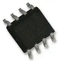
LED Driver Controller, 1 Output, Single Stage PFC, Flyback, 9.8 V to 26 V in, SOIC-8
- Manufacturer: INFINEON
- Product type: AC / DC LED Driver ICs
- Device Topology:Flyback; Input Voltage Min:9.8V; Input Voltage Max:26V; Output Voltage Max:10V; Output Current Max:-; Switching Frequency:-; No. of Outputs:1Outputs; IC Mounting:SMD;
- MSL: MSL 3 - 168 hours
- SVHC: No SVHC (25-Jun-2025)
- Topology: Flyback
- IC Mounting: Surface Mount
- No. of Pins: 8Pins
- Product Range: -
- Qualification: -
- No. of Outputs: 1Outputs
- Device Topology: Flyback
- LED Driver Type: Isolated
- Driver Case Style: SOIC
- IC Case / Package: SOIC
- Input Voltage Max: 26V
- Input Voltage Min: 9.8V
- Output Current Max: -
- Output Voltage Max: 10V
- Switching Frequency: -
- Switching Frequency Typ: -
- Operating Temperature Max: 130°C
- Operating Temperature Min: -25°C
- Automotive Qualification Standard: -
| Delivery and price | |
|---|---|
| Units per pack | 2500 |
| Price | 0.692 € |
| Current stock | 10+ |
| Lead time | 30 days |
## LED Controller IC

Single Stage PFC and Flyback LED Controller

ICL8002G

## Data Sheet

Rev1.0, 2012-02-28

Industrial and Multimarket ~~eee~~

## **Edition 2012-02-28**

**Published by Infineon Technologies AG 81726 Munich, Germany © 2012 Infineon Technologies AG All Rights Reserved.**

## **Legal Disclaimer**

The information given in this document shall in no event be regarded as a guarantee of conditions or characteristics. With respect to any examples or hints given herein, any typical values stated herein and/or any information regarding the application of the device, Infineon Technologies hereby disclaims any and all warranties and liabilities of any kind, including without limitation, warranties of non-infringement of intellectual property rights of any third party.

## **Information**

For further information on technology, delivery terms and conditions and prices, please contact the nearest Infineon Technologies Office ( **www.infineon.com** ).

## **Warnings**

Due to technical requirements, components may contain dangerous substances. For information on the types in question, please contact the nearest Infineon Technologies Office.

Infineon Technologies components may be used in life-support devices or systems only with the express written approval of Infineon Technologies, if a failure of such components can reasonably be expected to cause the failure of that life-support device or system or to affect the safety or effectiveness of that device or system. Life support devices or systems are intended to be implanted in the human body or to support and/or maintain and sustain and/or protect human life. If they fail, it is reasonable to assume that the health of the user or other persons may be endangered.

**Single Stage PFC and Flyback LED Controller ICL8002G**

**==> picture [131 x 63] intentionally omitted <==**

**Revision History Page or Item Subjects (major changes since previous revision) Rev1.0,2012-02-28**

## **<Revision X.Y>, <yyyy-mm-dd>**

## **Trademarks of Infineon Technologies AG**

AURIX™, BlueMoon™, C166™, CanPAK™, CIPOS™, CIPURSE™, COMNEON™, EconoPACK™, CoolMOS™, CoolSET™, CORECONTROL™, CROSSAVE™, DAVE™, EasyPIM™, EconoBRIDGE™, EconoDUAL™, EconoPIM™, EiceDRIVER™, eupec™, FCOS™, HITFET™, HybridPACK™, I²RF™, ISOFACE™, IsoPACK™, MIPAQ™, ModSTACK™, my-d™, NovalithIC™, OmniTune™, OptiMOS™, ORIGA™, PRIMARION™, PrimePACK™, PrimeSTACK™, PRO-SIL™, PROFET™, RASIC™, ReverSave™, SatRIC™, SIEGET™, SINDRION™, SIPMOS™, SMARTi™, SmartLEWIS™, SOLID FLASH™, TEMPFET™, thinQ!™, TRENCHSTOP™, TriCore™, X-GOLD™, X-PMU™, XMM™, XPOSYS™.

## **Other Trademarks**

Advance Design System™ (ADS) of Agilent Technologies, AMBA™, ARM™, MULTI-ICE™, KEIL™, PRIMECELL™, REALVIEW™, THUMB™, µVision™ of ARM Limited, UK. AUTOSAR™ is licensed by AUTOSAR development partnership. Bluetooth™ of Bluetooth SIG Inc. CAT-iq™ of DECT Forum. COLOSSUS™, FirstGPS™ of Trimble Navigation Ltd. EMV™ of EMVCo, LLC (Visa Holdings Inc.). EPCOS™ of Epcos AG. FLEXGO™ of Microsoft Corporation. FlexRay™ is licensed by FlexRay Consortium. HYPERTERMINAL™ of Hilgraeve Incorporated. IEC™ of Commission Electrotechnique Internationale. IrDA™ of Infrared Data Association Corporation. ISO™ of INTERNATIONAL ORGANIZATION FOR STANDARDIZATION. MATLAB™ of MathWorks, Inc. MAXIM™ of Maxim Integrated Products, Inc. MICROTEC™, NUCLEUS™ of Mentor Graphics Corporation. Mifare™ of NXP. MIPI™ of MIPI Alliance, Inc. MIPS™ of MIPS Technologies, Inc., USA. muRata™ of MURATA MANUFACTURING CO., MICROWAVE OFFICE™ (MWO) of Applied Wave Research Inc., OmniVision™ of OmniVision Technologies, Inc. Openwave™ Openwave Systems Inc. RED HAT™ Red Hat, Inc. RFMD™ RF Micro Devices, Inc. SIRIUS™ of Sirius Satellite Radio Inc. SOLARIS™ of Sun Microsystems, Inc. SPANSION™ of Spansion LLC Ltd. Symbian™ of Symbian Software Limited. TAIYO YUDEN™ of Taiyo Yuden Co. TEAKLITE™ of CEVA, Inc. TEKTRONIX™ of Tektronix Inc. TOKO™ of TOKO KABUSHIKI KAISHA TA. UNIX™ of X/Open Company Limited. VERILOG™, PALLADIUM™ of Cadence Design Systems, Inc. VLYNQ™ of Texas Instruments Incorporated. VXWORKS™, WIND RIVER™ of WIND RIVER SYSTEMS, INC. ZETEX™ of Diodes Zetex Limited.

Last Trademarks Update 2010-10-26

Data Sheet

3

Rev1.0, 2012-02-28

**Single Stage PFC and Flyback LED Controller ICL8002G**

**==> picture [131 x 63] intentionally omitted <==**

**Table of Contents**

## **Table of Contents**

||**Table of Contents**. . . . . . . . . . . . . . . . . . . . . . . . . . . . . . . . . . . . . . . . . . . . . . . . . . . . . . . . . . . . . . . .  4|
|---|---|
||**List of Figures**. . . . . . . . . . . . . . . . . . . . . . . . . . . . . . . . . . . . . . . . . . . . . . . . . . . . . . . . . . . . . . . . . . .  5|
||**List of Tables**. . . . . . . . . . . . . . . . . . . . . . . . . . . . . . . . . . . . . . . . . . . . . . . . . . . . . . . . . . . . . . . . . . . .  6|
|**1**|**Single Stage PFC and Flyback LED Controller**|
||**Product Highlight**. . . . . . . . . . . . . . . . . . . . . . . . . . . . . . . . . . . . . . . . . . . . . . . . . . . . . . . . . . . . . . . . 7|
|**2**|**Pin Configuration and Functionality**. . . . . . . . . . . . . . . . . . . . . . . . . . . . . . . . . . . . . . . . . . . . . . . . .  9|
|2.1|Pin Configuration with PG-DSO-8  . . . . . . . . . . . . . . . . . . . . . . . . . . . . . . . . . . . . . . . . . . . . . . . . . . . .  9|
|2.2|Package PG-DSO-8 . . . . . . . . . . . . . . . . . . . . . . . . . . . . . . . . . . . . . . . . . . . . . . . . . . . . . . . . . . . . . . .  9|
|2.3|Pin Functionality . . . . . . . . . . . . . . . . . . . . . . . . . . . . . . . . . . . . . . . . . . . . . . . . . . . . . . . . . . . . . . . . .  10|
|**3**|**Representative Block Diagram**. . . . . . . . . . . . . . . . . . . . . . . . . . . . . . . . . . . . . . . . . . . . . . . . . . . .  11|
|**4**|**Functional Description**. . . . . . . . . . . . . . . . . . . . . . . . . . . . . . . . . . . . . . . . . . . . . . . . . . . . . . . . . . .  12|
|4.1|VCC Pre-Charging and Typical VCC Voltage During Start-up . . . . . . . . . . . . . . . . . . . . . . . . . . . . . .  12|
|4.2|Soft-start . . . . . . . . . . . . . . . . . . . . . . . . . . . . . . . . . . . . . . . . . . . . . . . . . . . . . . . . . . . . . . . . . . . . . . .  13|
|4.3|Normal Operation . . . . . . . . . . . . . . . . . . . . . . . . . . . . . . . . . . . . . . . . . . . . . . . . . . . . . . . . . . . . . . . .  13|
|4.3.1|Zero Crossing  . . . . . . . . . . . . . . . . . . . . . . . . . . . . . . . . . . . . . . . . . . . . . . . . . . . . . . . . . . . . . . . . .  13|
|4.3.2|Ringing Suppression Time . . . . . . . . . . . . . . . . . . . . . . . . . . . . . . . . . . . . . . . . . . . . . . . . . . . . . . . .  14|
|4.3.2.1|Switch on Determination  . . . . . . . . . . . . . . . . . . . . . . . . . . . . . . . . . . . . . . . . . . . . . . . . . . . . . . .  14|
|4.3.3|Switch Off Determination . . . . . . . . . . . . . . . . . . . . . . . . . . . . . . . . . . . . . . . . . . . . . . . . . . . . . . . . .  14|
|4.4|Current Limitation . . . . . . . . . . . . . . . . . . . . . . . . . . . . . . . . . . . . . . . . . . . . . . . . . . . . . . . . . . . . . . . .  15|
|4.4.1|Foldback Point Correction . . . . . . . . . . . . . . . . . . . . . . . . . . . . . . . . . . . . . . . . . . . . . . . . . . . . . . . .  15|
|4.4.2|Additional Features in ICL8002G compare to ICL8001G . . . . . . . . . . . . . . . . . . . . . . . . . . . . . . . . . . 16|
|4.5|iProtection Functions  . . . . . . . . . . . . . . . . . . . . . . . . . . . . . . . . . . . . . . . . . . . . . . . . . . . . . . . . . . . . .  17|
|**5**|**Electrical Characteristics**. . . . . . . . . . . . . . . . . . . . . . . . . . . . . . . . . . . . . . . . . . . . . . . . . . . . . . . . .  18|
|5.1|Absolute Maximum Ratings  . . . . . . . . . . . . . . . . . . . . . . . . . . . . . . . . . . . . . . . . . . . . . . . . . . . . . . . .  18|
|5.2|Operating Range  . . . . . . . . . . . . . . . . . . . . . . . . . . . . . . . . . . . . . . . . . . . . . . . . . . . . . . . . . . . . . . . .  18|
|5.3|Characteristics  . . . . . . . . . . . . . . . . . . . . . . . . . . . . . . . . . . . . . . . . . . . . . . . . . . . . . . . . . . . . . . . . . .  19|
|5.3.1|Supply Section . . . . . . . . . . . . . . . . . . . . . . . . . . . . . . . . . . . . . . . . . . . . . . . . . . . . . . . . . . . . . . . . .  19|
|5.3.2|Internal Voltage Reference  . . . . . . . . . . . . . . . . . . . . . . . . . . . . . . . . . . . . . . . . . . . . . . . . . . . . . . .  19|
|5.3.3|PWM Section . . . . . . . . . . . . . . . . . . . . . . . . . . . . . . . . . . . . . . . . . . . . . . . . . . . . . . . . . . . . . . . . . .  20|
|5.3.4|Current Sense  . . . . . . . . . . . . . . . . . . . . . . . . . . . . . . . . . . . . . . . . . . . . . . . . . . . . . . . . . . . . . . . . .  20|
|5.3.5|Soft Start  . . . . . . . . . . . . . . . . . . . . . . . . . . . . . . . . . . . . . . . . . . . . . . . . . . . . . . . . . . . . . . . . . . . . .  20|
|5.3.6|Foldback Point Correction . . . . . . . . . . . . . . . . . . . . . . . . . . . . . . . . . . . . . . . . . . . . . . . . . . . . . . . .  21|
|5.3.7|Digital Zero Crossing . . . . . . . . . . . . . . . . . . . . . . . . . . . . . . . . . . . . . . . . . . . . . . . . . . . . . . . . . . . .  21|
|5.3.8|Protection . . . . . . . . . . . . . . . . . . . . . . . . . . . . . . . . . . . . . . . . . . . . . . . . . . . . . . . . . . . . . . . . . . . . .  22|
|5.3.9|Gate Drive  . . . . . . . . . . . . . . . . . . . . . . . . . . . . . . . . . . . . . . . . . . . . . . . . . . . . . . . . . . . . . . . . . . . .  22|
|**6**|**Outline Dimension**. . . . . . . . . . . . . . . . . . . . . . . . . . . . . . . . . . . . . . . . . . . . . . . . . . . . . . . . . . . . . .  23|
||**References**. . . . . . . . . . . . . . . . . . . . . . . . . . . . . . . . . . . . . . . . . . . . . . . . . . . . . . . . . . . . . . . . . . . .  24|
||**Terminology**. . . . . . . . . . . . . . . . . . . . . . . . . . . . . . . . . . . . . . . . . . . . . . . . . . . . . . . . . . . . . . . . . . .  25|


Data Sheet

Rev1.0, 2012-02-28

4

**Single Stage PFC and Flyback LED Controller ICL8002G**

**==> picture [131 x 63] intentionally omitted <==**

**Single Stage PFC and Flyback LED Controller Product Highlight**

## **1 Single Stage PFC and Flyback LED Controller Product Highlight**

- Quasi-Resonant Control For Highly Efficient LED Driving Solutions

- Primary Side Flyback Control With Integrated PFC And Phase-Cut Dimming

- Integrated HV Startup Cell For Short Time To Light

- Best In Class System BOM For Dimmable LED Bulb

- Continous Dimming curve for better diiming behaviour

## **Features**

- High, stable efficiency over wide operating range

- Optimized for trailing- and leading-edge dimmer

- Precise PWM for primary PFC and dimming control

- Power cell for Vcc pre-charging with constant current

- Built-in digital soft-start

- Foldback correction and cycle-by-cycle peak current limitation

- VCC over/ under-voltage lockout

- Auto restart mode for short circuit protection

- Adjustable latch-off mode for output overvoltage protection

- Minimize the light shimmering effect for better dimming behaviour.

- Enabling the input current shaping for higher PF and lower THD.

## **Description**

The ICL8002G employs quasi-resonant operation mode optimized for off-line LED lighting, especially dimmable LED bulbs for incandescent lamp replacement.

Precise PWM generation enables primary control for phase cut dimming and high power factor PF>98%. Significant improved driver efficiency, up to 90%, compared to other conventional solutions. Tthe product has a wide operation range (up to 26 V) of IC voltage supply and lower power consumption. Multiple safety functions ensure a full system protection in failure situations.

With its full feature set and simple application, the ICL8002G represents an outstanding choice for quasi-resonant flyback LED bulb designs combining feature set and performance at minimum BOM cost.

Data Sheet

Rev1.0, 2012-02-28

7

**Single Stage PFC and Flyback LED Controller ICL8002G**

**Single Stage PFC and Flyback LED Controller Product Highlight**

## **Application Circuit for Primary Control**

**Figure 1 Application Circuit Type Package** ICL8002G PG-DSO-8 ~~ee~~

Data Sheet

8

Rev1.0, 2012-02-28

**Single Stage PFC and Flyback LED Controller ICL8002G**

**==> picture [131 x 63] intentionally omitted <==**

**Pin Configuration and Functionality**

## **2 Pin Configuration and Functionality**

## **2.1 Pin Configuration with PG-DSO-8**

## **Table 1 Pin Description**

|**Ball No.**|**Name**|**Pin**<br>**Type**|**Buffer**<br>**Type**|**Function**|
|---|---|---|---|---|
|1|ZCV|–|–|**Zero Crossing**|
|2|VR|–|–|**Voltage Sense**|
|3|CS|–|–|**Current Sense**|
|4|GD|–|–|**Gate Drive Output**|
|5|HV|–|–|**High Voltage Input**|
|6|n.c.|–|–|**Not connected**|
|7|VCC|–|–|**Controller Supply Voltage**|
|8|GND|GND|–|**Controller Ground**|


## **2.2 Package PG-DSO-8**

**==> picture [173 x 197] intentionally omitted <==**

**----- Start of picture text -----**<br>
ZCV 1 8 GND<br>VR 2 7 VCC<br>CS 3 6 NC<br>GD 4 5 HV<br>PG_DSO_8_Top.vsd<br>**----- End of picture text -----**<br>


**Figure 2 Pin Configuration PG-DSO-8(top view)**

Data Sheet

9

Rev1.0, 2012-02-28

**Single Stage PFC and Flyback LED Controller ICL8002G**

**==> picture [131 x 63] intentionally omitted <==**

**Pin Configuration and Functionality**

## **2.3 Pin Functionality**

## **ZCV (Zero Crossing)**

At this pin, the voltage from the auxiliary winding after a time delay circuit is applied. Internally, this pin is connected to the zero-crossing detector for switch-on determination. Additionally, the output overvoltage detection is realized by comparing the voltage Vzc with an internal preset threshold.

## **VR (Voltage Sense)**

The rectified input mains voltage is sensed at this pin. The signal is used to set the peak current of the peak-current control and therefore allow for the PFC and phase-cut dimming functionality.

## **CS (Current Sense)**

This pin is connected to the shunt resistor for the primary current sensing, externally, and the PWM signal generator for switch-off determination (together with the feedback voltage), internally. Moreover, short-winding protection is realised by monitoring the voltage Vcs during on-time of the main power switch.

## **GD (Gate Drive Output)**

This output signal drives the external main power switch, which is a power MOSFET in most case.

## **HV (High Voltage)**

The pin HV is connected to the bus voltage, externally, and to the power cell, internally. The current through this pin pre-charges the VCC capacitor with constant current once the supply bus voltage is applied.

## **VCC (Power supply)**

VCC pin is the positive supply of the IC. The operating range is between VVCCoff and VVCCOVP.

## **GND (Ground)**

This is the common ground of the controller.

Data Sheet

10

Rev1.0, 2012-02-28

**Single Stage PFC and Flyback LED Controller ICL8002G**

**==> picture [131 x 63] intentionally omitted <==**

**Representative Block Diagram**

## **3**

## **Representative Block Diagram**

**==> picture [315 x 232] intentionally omitted <==**

**----- Start of picture text -----**<br>
VCC HV<br>Zero Crossing Power Managment Startup Cell<br>Zero  Over / Under- Voltage<br>ZCV Current Voltage Lockout Reference Depl. CoolMOS [®]<br>Detection & Biasing<br>GND<br>Over<br>Voltage  Protection Restart /  Gate Drive<br>Protection<br>LatchupControl ControlGate  GD<br>OTP<br>Foldback Short<br>Correction Winding<br>Detection<br>Current Mode Control<br>Softstart PWM<br>Comparator Leading<br>&  Edge  CS<br>VR PFC/ Blanking<br>Dimming<br>Control<br>BlockDiagram .vsd<br>**----- End of picture text -----**<br>


## **Figure 3 Representative Block Diagram**

Data Sheet

11

Rev1.0, 2012-02-28

**Single Stage PFC and Flyback LED Controller ICL8002G**

**==> picture [131 x 63] intentionally omitted <==**

**Functional Description**

## **4 Functional Description**

## **4.1 VCC Pre-Charging and Typical VCC Voltage During Start-up**

In ICL8002G, a high voltage startup cell is integrated. As shown in Figure 2, the start cell consists of a high voltage device and a controller, whereby the high voltage device is controlled by the controller. The startup cell provides a pre-charging of the VCC capacitor till VCC voltage reaches the VCC turned-on threshold VVCCon and the IC begins to operate.

Once the mains input voltage is applied, a rectified voltage shows across the capacitor Cbus. The high voltage device provides a current to charge the VCC capacitor Cvcc. Before the VCC voltage reaches a certain value, the amplitude of the current through the high voltage device is only determined by its channel resistance and can be as high as several mA. After the VCC voltage is high enough, the controller controls the high voltage device so that a constant current around 1mA is provided to charge the VCC capacitor further, until the VCC voltage exceeds the turned-on threshold VVCCon. As shown as the time phase I in Figure 3, the VCC voltage increase near linearly and the charging speed is independent of the mains voltage level.

**==> picture [400 x 175] intentionally omitted <==**

**----- Start of picture text -----**<br>
VVCC<br>i ii iii<br>V<br>VCCon<br>VVCCoff<br>t1 t2 t<br>**----- End of picture text -----**<br>


**Figure 4 VCC voltage at start up**

The time taking for the VCC pre-charging can then be approximately calculated as:

**==> picture [140 x 51] intentionally omitted <==**

**==> picture [14 x 10] intentionally omitted <==**

where IVCCcharge2 is the charging current from the startup cell which is 1.05mA, typically.

Exceeds the VCC voltage the turned-on threshold VVCCon of at time t1, the startup cell is switched off, and the IC begins to operate with a soft-start. Due to power consumption of the IC and the fact that still no energy from the auxiliary winding to charge the VCC capacitor before the output voltage is built up, the VCC voltage drops (Phase II). Once the output voltage is high enough, the VCC capacitor receives then energy from the auxiliary winding from the time point t2 on. The VCC then will reach a constant value depending on output load.

Data Sheet

12

Rev1.0, 2012-02-28

**Single Stage PFC and Flyback LED Controller ICL8002G**

**==> picture [131 x 63] intentionally omitted <==**

## **Functional Description**

## **4.2 Soft-start**

At the time ton, the IC begins to operate with a soft-start. By this soft-start the switching stresses for the switch, diode and transformer are minimised. The soft-start implemented in ICL8002G is a digital time-based function. The preset soft-start time is 12ms with 4 steps. If not limited by other functions, the peak voltage on CS pin will increase step by step from 0.32 V to 1 V finally.

**==> picture [433 x 245] intentionally omitted <==**

**----- Start of picture text -----**<br>
Vcs_sst<br>(V)<br>1.00<br>0.83<br>0.66<br>0.49<br>0.32<br>ton 3 6 9 12 Time(ms)<br>**----- End of picture text -----**<br>


## **Figure 5 Maximum current sense voltage during softstart**

## **4.3 Normal Operation**

The PWM controller during normal operation consists of a digital signal processing circuit including a comparator, and an analog circuit including a current measurement unit and a comparator. The switch-on and -off time points are each determined by the digital circuit and the analog circuit, respectively. As input information for the switchon determination, the zero-crossing input signal is needed, while the voltages sense signal at pin VR and the current sensing signal VCS are necessary for the switch-off determination. Details about the full operation of the PWM controller in normal operation are illustrated in the following paragraphs.

## **4.3.1 Zero Crossing**

In the system, the voltage from the auxiliary winding is applied to the zero-crossing pin through a RC network, which provides a time delay to the voltage from the auxiliary winding. Internally, this pin is connected to a clamping network, a zero-crossing detector, an output overvoltage detector and a ringing suppression time controller.

During on-state of the power switch a negative voltage applies to the ZCV pin. Through the internal clamping network, the voltage at the pin is clamped to -0.3V.

The voltage VZC is also used for the output overvoltage protection. Once the voltage at this pin is higher than the threshold VZCOVP during off-time of the main switch, the IC is latched off after a fixed blanking time.

To achieve the switch-on at voltage valley, the voltage from the auxiliary winding is fed to a time delay network (the RC network consists of Dzc, Rzc1, Rzc2 and Czc as shown in typical application circuit) before it is applied to the zero-crossing detector through the ZC pin. The needed time delay to the main oscillation signal Dt should be approximately one fourth of the oscillation period (by transformer primary inductor and drain-source capacitor)

Data Sheet

13

Rev1.0, 2012-02-28

**Single Stage PFC and Flyback LED Controller ICL8002G**

**==> picture [131 x 63] intentionally omitted <==**

**Functional Description**

minus the propagation delay from thedetected zero-crossing to the switch-on of the main switch tdelay, theoretically:

**==> picture [129 x 39] intentionally omitted <==**

**==> picture [14 x 11] intentionally omitted <==**

This time delay should be matched by adjusting the time constant of the RC network which is calculated as:

**==> picture [219 x 49] intentionally omitted <==**

**==> picture [14 x 11] intentionally omitted <==**

## **4.3.2 Ringing Suppression Time**

After MOSFET is turned off, there will be some oscillation on VDS, which will also appear on the voltage on ZC pin. To avoid that the MOSFET is turned on mistriggerred by such oscillations, a ringing suppression timer is implemented. The timer is dependent on the voltage VZC. When the voltage VZC is lower than the threshold VZCRS, a longer preset time applies, while a shorter time is set when the voltage VZC is higher than the threshold.

## **4.3.2.1 Switch on Determination**

After the gate drive goes to low, it can not be changed to high during ring suppression time.

After ring suppression time, the gate drive can be turned on when the zero crossing is detected.

However, it is also possible that the oscillation between primary inductor and drain-source capacitor damps very fast and IC can not detect a zero crossing. In this case, a maximum off time is implemented. After gate drive has been remained off for the period of tOffMax, the gate drive will be turned on again regardless. This function can effectively prevent the switching frequency from going lower than 20kHz, otherwise which will cause audible noise, during start up.

## **4.3.3 Switch Off Determination**

In the converter system, the primary current is sensed by an external shunt resistor, which is connected between low-side terminal of the main power switch and the common ground. The sensed voltage across the shunt resistor VCS is applied to an internal current measurement unit, and its output voltage V1 is compared with the voltage at pin VR. Once the voltage V1 exceeds the voltage VVR, the output flip-flop is reset. As a result, the main power switch is switched off. The relationship between the V1 and the VCS is described by:

**==> picture [137 x 18] intentionally omitted <==**

**==> picture [14 x 11] intentionally omitted <==**

To avoid mistriggering caused by the voltage spike across the shunt resistor at the turn on of the main power switch, a leading edge blanking time, tLEB, is applied to the output of the comparator. In other words, once the gate drive is turned on, the minimum on time of the gate drive is the leading edge blanking time.

In addition, there is a maximum on time, tOnMax, limitation implemented in the IC. Once the gate drive has been in high state longer than the maximum on time, it will be turned off to prevent the switching frequency from going too low because of long on time.

Data Sheet

14

Rev1.0, 2012-02-28

**Single Stage PFC and Flyback LED Controller ICL8002G**

**==> picture [131 x 63] intentionally omitted <==**

## **Functional Description**

## **4.4 Current Limitation**

There is a cycle by cycle current limitation realized by the current limit comparator to provide an overcurrent detection. The source current of the MOSFET is sensed via a sense resistor RCS. By means of RCS the source current is transformed to a sense voltage VCS which is fed into the pin CS. If the voltage VCS exceeds an internal voltage limit, adjusted according to the Mains voltage, the comparator immediately turns off the gate drive.

To prevent the Current Limitation process from distortions caused by leading edge spikes, a Leading Edge Blanking time (tLEB) is integrated in the current sensing path.

A further comparator is implemented to detect dangerous current levels (VCSSW) which could occur if one or more transformer windings are shorted or if the secondary diode is shorted. To avoid an accidental latch off, a spike blanking time of tCSSW is integrated in the output path of the comparator.

## **4.4.1 Foldback Point Correction**

When the main bus voltage increases, the switch on time becomes shorter and therefore the operating frequency is also increased. As a result, for a constant primary current limit, the maximum possible output power is increased, which the converter may have not been designed to support.

To avoid such a situation, the internal foldback point correction circuit varies the VCS voltage limit according to the bus voltage. This means the VCS will be decreased when the bus voltage increases. To keep a constant maximum input power of the converter, the required maximum VCS versus various input bus voltage can be calculated, which is shown in **Figure 6** .

**==> picture [475 x 290] intentionally omitted <==**

**----- Start of picture text -----**<br>
1<br>0.9<br>0.8<br>0.7<br>0.6<br>80 100 120 140 160 180 200 220 240 260 280 300 320 340 360 380 400<br>Vin(V)<br>Vcs-max(V)<br>**----- End of picture text -----**<br>


**Figure 6 Variation of the VCS limit voltage according to the IZC current**

Data Sheet

15

Rev1.0, 2012-02-28

**Single Stage PFC and Flyback LED Controller ICL8002G**

**==> picture [131 x 63] intentionally omitted <==**

## **Functional Description**

According to the typical application circuit, when MOSFET is turned on, a negative voltage proportional to bus voltage will be coupled to auxiliary winding. Inside ICL8002G, an internal circuit will clamp the voltage on ZC pin to nearly 0 V. As a result, the current flowing out from ZC pin can be calculated as

**==> picture [147 x 47] intentionally omitted <==**

**==> picture [14 x 10] intentionally omitted <==**

When this current is higher than IZC_1, the amount of current exceeding this threshold is used to generate an offset to decrease the maximum limit on VCS. Since the ideal curve shown in **Figure 6** is a nonlinear one, a digital block in ICL8002G is implemented to get a better control of maximum output power. Additional advantage to use digital circuit is the production tolerance is smaller compared to analog solutions. The typical maximum limit on VCS versus the ZC current is shown in **Figure 7** .

**==> picture [475 x 291] intentionally omitted <==**

**----- Start of picture text -----**<br>
1<br>0.9<br>0.8<br>0.7<br>0.6<br>300 500 700 900 1100 1300 1500 1700 1900 2100<br>Izc(uA)<br>Vcs-max(V)<br>**----- End of picture text -----**<br>


## **Figure 7 VCS-max versus IZCi**

## **4.4.2 Additonal Features in ICL8002G compare to ICL8001G**

1) New Valley Switching Sheme which minimizes light shimmer effect.

- 2) Helps for the continous dimming curve for smooth dimming.

- 3) Internal hold-up resistor value has been increased for better shaping of the input current.

- 4) Better shaping of the input current results in high PFC and stable dimming at higher LED current precision.

- 5) Better PFC leads to lower THD operation to meet the EN standards for hormonics.

Data Sheet

16

Rev1.0, 2012-02-28

**Single Stage PFC and Flyback LED Controller ICL8002G**

**==> picture [131 x 63] intentionally omitted <==**

## **Functional Description**

## **4.5 iProtection Functions**

The IC provides full protection functions. The following table summarizes these protection functions.

Table 2 Protection features

|Table 2<br>Protection features||
|---|---|
|VCC Overvoltage|Auto Restart Mode|
|VCC Undervoltage|Auto Restart Mode|
|Over temperature|Auto Restart Mode|
|Output Overvoltage|Latched Off Mode|
|Short Winding|Latched Off Mode|


During operation, the VCC voltage is continuously monitored. In case of an under- or an over-voltage, the IC is reset and the main power switch is then kept off. After the VCC voltage falls below the threshold VVCCoff, the startup cell is activated. The VCC capacitor is then charged up. Once the voltage exceeds the threshold VVCCon, the IC begins to operate with a new soft-start.

During off-time of the power switch, the voltage at the zero-crossing pin is monitored for output over-voltage detection. If the voltage is higher than the preset threshold VZCOVP, the IC is latched off after the preset blanking time.

> There is also the overvoltage protection being implemented at VR, when this voltage exceeds _V_ VROVP, the device goes into Auto Restart Mode.

If the junction temperature of IC exceeds 140[0] C, the IC enter into autorestart mode.

If the voltage at the current sensing pin is higher than the preset threshold VCSSW during on-time of the power switch, the IC is latched off. This is short-winding protection.

During latch-off protection mode, when the VCC voltage drops to 10.5 V,the startup cell is activated and the VCC voltage is charged to 18 V then the startup cell is shut down again and repeats the previous procedure.

There is also a maximum on time limitation inside ICL8002G. Once the gate voltage is high longer than tOnMAx, it is turned off immediately.

Data Sheet

17

Rev1.0, 2012-02-28

**Single Stage PFC and Flyback LED Controller ICL8002G**

**==> picture [131 x 63] intentionally omitted <==**

**Electrical Characteristics**

## **5 Electrical Characteristics**

_Note: All voltages are measured with respect to ground (Pin 8). The voltage levels are valid if other ratings are not violated._

## **5.1 Absolute Maximum Ratings**

_Note: Absolute maximum ratings are defined as ratings, which when being exceeded may lead to destruction of the integrated circuit. For the same reason make sure, that any capacitor that will be connected to pin 7 ( V CC) is discharged before assembling the application circuit._

## **Table 3 Absolute Maximum Ratings**

|**Parameter**|**Symbol**|**Values**|**Values**|**Unit**|**Note / Test Condition**|
|---|---|---|---|---|---|
|||**Min.**|**Max.**|||
|HV Voltage|_V_HV|–|500|V||
|_VCC_Supply Voltage|_V_VCC|-0.3|27|V||
|VR Voltage|_V_VR|-0.3|5.0|V||
|ZCV Voltage|_V_ZC|-0.3|5.0|V||
|CS Voltage|_V_CS|-0.3|5.0|V||
|GD Voltage|_V_OUT|-0.3|27|V||
|Maximum current out from ZC pin|_I_ZCMAX|3|–|mA||
|Junction Temperature|_T_J|-40|150|°C||
|Storage Temperature|_T_S|-55|150|°C||
|Thermal Resistance Junction - Ambient|_R_thJA|–|185|K/W|PG-DSO-8|
|ESD Capability (incl. Drain Pin)|_V_ESD|–|2|kV|Human body model1)|


1) According to EIA/JESD22-A114-B (discharging a 100pF capacitor through a 1.5 kOhm series resistor).

## **5.2 Operating Range**

_Note: Within the operating range the IC operates as described in the functional description._

## **Table 4 Operating Range**

|**Parameter**|**Symbol**|**Values**|**Values**|**Values**|**Unit**|**Note / Test Condition**|
|---|---|---|---|---|---|---|
|||**Min.**|**Typ.**|**Max.**|||
|_VCC_Supply Voltage|_V_VCC|_V_VCCoff|–|_V_VCCOP|V||
|Junction Temperature of Controller|_T_jCON|-25|–|130|°C|_T_jCON<_T_J, Limited by over<br>temperature protection|


Data Sheet

18

Rev1.0, 2012-02-28

**Single Stage PFC and Flyback LED Controller ICL8002G**

**==> picture [131 x 63] intentionally omitted <==**

## **Electrical Characteristics**

## **5.3 Characteristics**

## **5.3.1 Supply Section**

_Note: The electrical characteristics involve the spread of values within the specified supply voltage and junction temperature range T J from – 25_ ° _C to 130_ ° _C. Typical values represent the median values, which are related to 25_ ° _C. If not otherwise stated, a supply voltage of V CC = 18 V is assumed._

## **Table 5 Supply Section**

|**Table 5**<br>**Supply Section**|||||||
|---|---|---|---|---|---|---|
|**Parameter**|**Symbol**|**Values**|||**Unit**|**Note / Test Condition**|
|||**Min.**|**Typ.**|**Max.**|||
|Start Up Current|_I_VCCstart|–|300|550|µA|_V_VCC=_V_VCCon-0.2 V|
|VCC Charge Current|_I_VCCcharge1|–|5.0|–|mA|_V_VCC= 0 V|
||_I_VCCcharge2|0.8||–|mA|_V_VCC= 1 V|
||_I_VCCcharge3|–|1.0|–|mA|_V_VCC=_V_VCCon-0.2 V|
|Maximum Input Current ofStartup Cell<br>and CoolMOS®|_I_DrainIn|–|–|2|mA|_V_VCC=_V_VCCon-0.2 V|
|Leakage Current ofStartup Cell|_I_StartLeak|–|0.2|50|µA|_V_HV =_610_V_at T_j= 100°C|
|Supply Current in normal operation|_I_VCCNM|–|1.5|2.3|mA|_VVR=0 V and no switching_|
|Supply Current in Auto Restart Mode<br>with Inactive Gate|_I_VCCAR|–|300|–|µA|_I_VR= 0 A|
|Supply Current in Latch-off Mode|_I_VCClatch|–|300|–|µA||
|VCC Turn-On Threshold|_V_VCCon|17.0|18.0|19.0|V||
|VCC Turn-Off Threshold|_V_VCCoff|9.8|10.5|11.2|V||
|VCC Turn-On/Off Hysteresis|_V_VCChys|–|7.5|–|V||


## **5.3.2 Internal Voltage Reference**

## **Table 6 Internal Voltage Reference**

|**Parameter**|**Symbol**|**Values**|**Values**|**Values**|**Unit**|**Note / Test Condition**|
|---|---|---|---|---|---|---|
|||**Min.**|**Typ.**|**Max.**|||
|Internal Reference Voltage|_V_REF|4.80|5.00|5.20|V|Measured at pin VR_I_VR = 0|


Data Sheet

19

Rev1.0, 2012-02-28

**Single Stage PFC and Flyback LED Controller ICL8002G**

**==> picture [131 x 63] intentionally omitted <==**

## **Electrical Characteristics**

## **5.3.3 PWM Section**

## **Table 7 PWM Section**

|**Table 7**<br>**PWM Section**|||||||
|---|---|---|---|---|---|---|
|**Parameter**|**Symbol**|**Values**|||**Unit**|**Note / Test Condition**|
|||**Min.**|**Typ.**|**Max.**|||
|VR Refrence Pull-Up Resistor|_R_VR|76|100|150|kΩ||
|PWM-OP Gain|_G_PWM|3.23|3.3|3.33|–||
|Offset for Voltage Ramp|_V_PWM|0.636|0.7|0.786|V||
|Maximum on time in normal operation|_t_OnMax|22|30|41|µs||


## **5.3.4 Current Sense**

## **Table 8 Current Sense**

|**Table 8**<br>**Current Sense**|||||||
|---|---|---|---|---|---|---|
|**Parameter**|**Symbol**|**Values**|||**Unit**|**Note / Test Condition**|
|||**Min.**|**Typ.**|**Max.**|||
|Peak current limitation in normal<br>operation|_V_CSth|0.97|1.03|1.09|V||
|Leading Edge Blanking time|_t_LEB|200|330|460|ns||


## **5.3.5 Soft Start**

## **Table 9 Soft Start**

|**Table 9**<br>**Soft Start**|||||||
|---|---|---|---|---|---|---|
|**Parameter**|**Symbol**|**Values**|||**Unit**|**Note / Test Condition**|
|||**Min.**|**Typ.**|**Max.**|||
|Soft-Start time|_t_SS|8.5|12|–|ms||
|Soft-start time step|_t_SS_S<br>1)|–|3|–|ms||
|Internal regulation voltage<br>at first step|_V_CSth<br>1)|–|1.76|–|V||
|Internal regulation voltage<br>step at soft start|_V_CSth<br>1)|–|0.56|–|V||


1) The parameter is not subjected to production test - verified by design/characterization

Data Sheet

20

Rev1.0, 2012-02-28

**Single Stage PFC and Flyback LED Controller ICL8002G**

**==> picture [131 x 63] intentionally omitted <==**

## **Electrical Characteristics**

## **5.3.6 Foldback Point Correction**

## **Table 10 Foldback Point Correction**

|**Parameter**|**Symbol**|**Values**|**Values**|**Values**|**Unit**|**Note / Test Condition**|
|---|---|---|---|---|---|---|
|||**Min.**|**Typ.**|**Max.**|||
|ZCV current first step threshold|_I_ZC_FS|0.35|0.5|0.621|mA||
|ZCV current last step threshold|_I_ZC_LS|1.3|1.7|2.2|mA||
|CS threshold minimum|_V_CSMF|–|0.66|–|V|_I_ZC = 2.2 mA,_V_VR = 3.8 V|


## **5.3.7 Zero Crossing**

## **Table 11 Zero Crossing**

|**Table 11**<br>**Zero Crossing**|||||||
|---|---|---|---|---|---|---|
|**Parameter**|**Symbol**|**Values**|||**Unit**|**Note / Test Condition**|
|||**Min.**|**Typ.**|**Max.**|||
|Zero crossing threshold voltage|_V_ZCCT|50|100|170|mV||
|Ringing suppression threshold|_V_ZCRS|–|0.7|–|V||
|Minimum ringing suppression time|_t_ZCRS1|1.62|2.5|4.5|µs|_V_ZC _> V_ZCRS|
|Maximum ringing suppression time|_t_ZCRS2|–|25|–|µs|_V_ZC _< V_ZCRS|
|Maximum restart time in normal<br>operation|_t_OffMax|30|42|57.5|µs||


Data Sheet

21

Rev1.0, 2012-02-28

**Single Stage PFC and Flyback LED Controller ICL8002G**

**==> picture [131 x 63] intentionally omitted <==**

## **Electrical Characteristics**

## **5.3.8 Protection**

## **Table 12 Protection**

|**Table 12**<br>**Protection**|||||||
|---|---|---|---|---|---|---|
|**Parameter**|**Symbol**|**Values**|||**Unit**|**Note / Test Condition**|
|||**Min.**|**Typ.**|**Max.**|||
|VCC overvoltage threshold|_V_VCCOVP|24.0|25.0|26.0|V||
|Output Overvoltage detection<br>threshold at the ZCV pin|_V_ZCOVP|3.55|3.7|3.84|V||
|Overvoltage protection threshold at<br>the VR pin|_V_VROVP||4.5||V||
|Overvoltage protection threshold<br>Blanking time at VR pin|_t_OVP_B|20|30|44|ms||
|Blanking time for Output Overvoltage<br>protection|_t_ZCOVP|–|100|–|µs||
|Threshold for short winding protection|_V_CSSW|1.63|1.68|1.78|V||
|Blanking time for short-windding<br>protection|_t_CSSW|–|190|–|ns||
|Over temperature protection1)|_T_jCon|130|140|150|°C||


1) The parameter is not subjected to production test - verified by design/characterization

_Note: The trend of all the voltage levels in the Control Unit is the same regarding the deviation except VVCCOVP_

## **5.3.9 Gate Drive**

## **Table 13 Gate Drive**

|**Table 13**<br>**Gate Drive**|||||||
|---|---|---|---|---|---|---|
|**Parameter**|**Symbol**|**Values**|||**Unit**|**Note / Test Condition**|
|||**Min.**|**Typ.**|**Max.**|||
|Output voltage at logic low|_V_GATElow|–|–|1.0|V|_V_VCC= 18 V<br>_I_OUT = 10 mA|
|Output voltage at logic high|_V_GATEhigh|9.0|10.0|–|V|_V_VCC= 18 V<br>_I_OUT = -10 mA|
|Output voltage active shut down|_V_GATEasd|–|–|1.0|V|_V_VCC= 7 V<br>_I_OUT = 10 mA|
|Rise Time|_t_rise|–|117|–|ns|_C_OUT= 1.0 nF<br>_V_GATE = 2 V ... 8 V|
|Fall Time|_t_fall|–|27|–|ns|_C_OUT= 1.0 nF<br>_V_GATE = 8 V ... 2 V|


Data Sheet

22

Rev1.0, 2012-02-28

**Single Stage PFC and Flyback LED Controller ICL8002G**

**==> picture [131 x 63] intentionally omitted <==**

## **Outline Dimension**

## **6**

## **Outline Dimension**

**==> picture [482 x 569] intentionally omitted <==**

**Figure 8 PG-DSO-8 (Pb-free lead plating Plastic Dual Small Outline)**

Dimensions in mm.

Data Sheet

23

Rev1.0, 2012-02-28

w w w . i n f i n e o n . c o m

Published by Infineon Technologies AG
Updated at March 15, 2026
Infineon Technologies is a globally recognized leader in semiconductor solutions, renowned for driving innovation in power management, energy efficiency, and modern mobility. With a strong legacy of engineering excellence, the company provides highly reliable components designed to meet the rigorous demands of industrial, automotive, and advanced commercial applications. The core of our Infineon portfolio is centered on their industry-leading discrete semiconductors. We offer an extensive selection of single and dual MOSFETs, alongside a robust range of single IGBTs and advanced IGBT modules. These flagship power transistors are essential for high-efficiency power conversion and motor control, providing engineers with superior thermal performance and minimized switching losses. Beyond advanced field-effect transistors, the selection includes a comprehensive array of diodes and rectifiers, heavily featuring Schottky diodes, as well as fast-recovery and RF/PIN diodes. This power foundation is further supported by bipolar transistors, intelligent power modules, and thyristor SCR modules, delivering the critical building blocks required for complex power system designs. To support broader system integration, the portfolio also encompasses specialized solutions such as solid-state relays, AC/DC LED driver ICs, and Bluetooth communications modules. From high-power industrial rectifiers to wireless connectivity adapters, Infineon equips designers with the precision components needed to build efficient, scalable, and fully connected electronic systems.
About Novapart
Novapart is a B2B electronic component broker specialising in stock shortages and cost reduction. We source hard-to-find parts and identify compliant alternatives across a catalogue of 410,000+ components from 500+ manufacturers.
Learn more →Stock Shortage Specialist
When a component is unavailable, discontinued or has an unacceptable lead time, we tap into our network of vetted European and Asian distributors to source what you need — without compromising on quality or traceability.
Request a quote →Compliant Alternatives
We identify pin-to-pin, electrically equivalent substitutes that meet the same certifications (RoHS, AEC-Q100, REACH) as your original specification — validated against datasheets, not just part numbers. Often at a lower cost.
BOM Analysis service →