
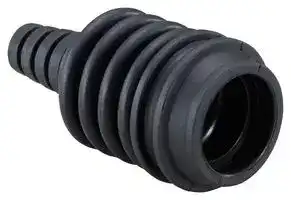


HW9Z-CZ1.
TERMINAL RUBBER BOOT, ILLUMINATED BUZZER
- Manufacturer: IDEC
- Product type: Signal Indicator Accessories
- For Use With: IDEC HW1Z Series 22mm Illuminated Buzzers
- Product Range: HW1Z Series
- Accessory Type: Terminal Rubber Boot
| Delivery and price | |
|---|---|
| Units per pack | 100 |
| Price | 4.91 € |
| Current stock | 10+ |
| Lead time | 30 days |
## **ø22mm HW1Z Illuminated Buzzer**

## Optimal illuminated buzzer for elevators and production sites

■ Combination buzzer and pilot light ■ Alerts workers of danger with sound and light ■ Waterproof construction

## HW1Z Illuminated Buzzer

## Complies with the new EU elevator safety standard

EN81-1/2, the safety rules for the construction and installation of lifts (electric and hydraulic) were revised to EN81-20/50 in July 2014 (effective in September 2017). As GB and JIS standards will follow suit, the requirements in the new rules must be taken into consideration when designing elevators.

EN81-20 (5.12.1.8.3 g)

An audible signal at the car and a flashing light under the car shall be activated during movement. The sound level of the audible warning shall be minimum 55 dB(A) below the car at 1 m distance.

## Can be used in semi-outdoor applications

With waterproof and dustproof construction, HW1Z can be used in semi-outdoor applications such as elevators exposed to rain and dust.

## Meets waterproof requirements for fireman’s elevator

**==> picture [74 x 47] intentionally omitted <==**

**----- Start of picture text -----**<br>
HW1Z’s IPX3 waterproof<br>characteristics can be<br>used in emergency<br>situations exposed to<br>water.<br>**----- End of picture text -----**<br>


## HW1Z Illuminated Buzzer

## Buzzer/lamp in one can be installed easy and quick

## Easy wiring and tight installation places

Wiring is accomplished with push-in terminals. No tightening of screw is required.

Short, 19.7 mm depth behind panel. Can be installed in tight places.

**==> picture [31 x 7] intentionally omitted <==**

**----- Start of picture text -----**<br>
19.7 mm<br>**----- End of picture text -----**<br>


Lamp and buzzer functions are integrated.

**==> picture [85 x 17] intentionally omitted <==**

**----- Start of picture text -----**<br>
Flashing light<br>**----- End of picture text -----**<br>


## Buzzer sound

## Waterproof construction

Panel front: IP65 waterproof

Installing an optional terminal rubber boot upgrades the terminal’s waterproof characteristics to IP54 without the need to use a rear enclosure.

—Other Applications—

01

## HW1Z Illuminated Buzzer

## [Automatic Storage]

Flashing lights and buzzer sounds alert workers of fast-moving parts in automatic storages.

## [Production Lines]

02

Installed in areas where robots operate, HW1Z alerts workers when they enter potentially hazardous locations.

## [AGV]

## [Control Station]

**==> picture [12 x 9] intentionally omitted <==**

**----- Start of picture text -----**<br>
03<br>**----- End of picture text -----**<br>


04

HW1Z can be used to alert workers of AGV movement. Also suitable for applications where multiple buzzers are required, such as in a control station.

ø22mm HW1Z Illuminated Buzzer

## **Model**

Shape Part No. Illumination Color HW1Z HW1Z-P1F2PQ4R Red HW1Z-P1F2PQ4Y Yellow ~~TT \o~~ **Accessories** Shape Material Part No. Package Quantity Notes Terminal Rubber Boot Applicable cable: ø4.5 to 8.5 mm Nitryl Rubber HW9Z-CZ1 1 Cut the end of rubber boot to fit the cable size (see dimensions). Weight: 10 g (approx.)

|**Specifications**<br>~~RO~~|**Specifications**<br>~~RO~~|**Specifications**<br>~~RO~~|**Specifications**<br>~~RO~~|**Specifications**<br>~~RO~~|
|---|---|---|---|---|
|RatedInsulation Voltage<br>RatedVoltage|30V<br>12 to24V DC||Operating<br>Temperature|–20 to +50ºC (no freezing)|
|VoltageRange<br>Rated Current(effective value)<br>InrushCurrent<br>Buzzer<br>Sound Pressure<br>(of HW1Z itself)<br>(at 25ºC)<br>Sound Frequency<br>(at 25ºC)<br>SoundType<br>Intermittent Cycle<br>(at 25ºC)<br>Illumination Type|10.8to26.4V DC<br>18mA(24V DC),8mA(12V DC)<br>100mA maximum<br>90dB min. at 0.1m (24VDC)<br>70dB min. at 1m (24V DC, equivalent value)<br>84dB min. at 0.1m (12V DC)<br>64dB min. at 1m (12VDC, equivalent value)<br>2,200 to 2,450Hz<br>Intermittentsound<br>105 cycles/minute approx. (1.75Hz approx.)<br>Flashing||OperatingHumidity<br>Storage<br>Temperature<br>Insulation<br>Resistance<br>Dielectric Strength<br>Vibration Resistance <br>Shock Resistance<br>Degree of Protection<br>Terminal Style|20% to 85% RH(no condensation)<br>–30 to +80ºC (no freezing)<br>100MΩ minimum (at 500V DC megger)<br>Between live and earthed metalparts: 1000V AC,1 minute<br> Operation extremes: 5 to 55Hz, amplitude 0.5mm<br>Damage limits: 5 to 55Hz, amplitude 0.5mm<br>Operation extremes: 100 m/s2<br>Damage limits: 1,000 m/s2<br>Panel front: IP65 (IEC 60529)<br>Terminal: IP40 (IEC 60529)<br>IP54 (with terminal rubber boot) (IEC 60529)<br>Push-in Terminals|
|Illumination<br>Flash Cycle<br>(at 25ºC)|105 cycles/minute approx. (1.75Hz approx.)||Applicable Wire<br>Weight(approx.)|Solid wire/ferrule (without sleeve): 0.2 to 1.5 mm2<br>Ferrule (with sleeve): 0.2 to 0.75 mm2<br>17g|


## Applicable Standards

UL508 File No.E68961 EN60947-5-1 EMC Directive ~~ee« ee~~

## Dimensions

## With terminal rubber boot

All dimensinos in mm.

**==> picture [484 x 120] intentionally omitted <==**

**----- Start of picture text -----**<br>
Cut here when cable size is ø5.5 to 6.5 (*1)<br>Rubber Gasket Panel Thickness 0.8 to 6 mm Cut here when cable size is ø6.5 to 7.5 (*1)<br>Locking i  Rin l g y plait Cut here when cable size is ø7.5 to 8.5 (*1) Afl ( CX<br>0.5 Bellows (*2)<br>19.7 17.6 17 to 22<br>54 to 59<br>58 to 63 *1: ø4.5-5.5 cable needs no cutting.<br>62 to 67 *2: The bellows must be 17 to 22mm long after installing<br>66 to 71 the terminal rubber boot.<br>SS<br>*3: Maintain a cable angle of 45° max. to the HW1Z axis.<br>ø33.3 ø30<br>45° max. (*3)<br>**----- End of picture text -----**<br>


## Terminal Arrangement (botom view)

**==> picture [43 x 32] intentionally omitted <==**

**----- Start of picture text -----**<br>
X2 X1<br>X1 and X2<br>have no polarity. =i<br>**----- End of picture text -----**<br>


## Mounting Hole Layout

**==> picture [154 x 70] intentionally omitted <==**

**----- Start of picture text -----**<br>
3.2 [+0.2] 0 [ ∗]<br>Panel cut-out ∗ 3.2       hole is for anti-rotation.+0.20<br>Not required when nameplate/anti-rotation is not used.<br>R0.8 max.<br>ø22.3+0.40<br>+0.4 0<br>24.1<br>**----- End of picture text -----**<br>


ø22mm HW1Z Illuminated Buzzer

## ~~aaa~~ ~~**Safety Precautions**~~

- Turn off the power to the HW1Z before installation, removal, wiring, maintenance, and inspection. Failure to turn power off may cause electrical shocks or fire hazard.

   - Prevent metal fragments and pieces of wire from dropping inside when installing or wiring the HW1Z. Otherwise fire, failure, or malfunction may be caused.

- For wiring, use wires of a proper gauge to meet the voltage and current requirements.

**Operating Instructions** ~~bo~~ Panel Mounting 4. Install the terminal rubber boot as shown below. • Insert the HW1Z into the panel cut-out from the front, and tighten the locking ring from the back.

- Insert the HW1Z into the panel cut-out from the front, and tighten the locking ring from the back. Panel

- Note for panel mounting • Use the optional locking ring wrench (MW9Z-T1) to tighten the locking ring to a recommended tightening torque of 1.5 to 2.0 N·m. Locking Ring

- • Do not use pliers and do not tighten excessively, otherwise the HW1Z may be damaged. 4,

**==> picture [227 x 366] intentionally omitted <==**

**----- Start of picture text -----**<br>
we<br>5. Cover part B with part A.<br>ee<br>Installed<br>Part B Part A (terminal rubber boot: cross section view)<br>bi ai<br>6. Make sure that the bellows is 17 to 22 mm long.<br>Bellows<br>Note for terminal rubber boot =<br>• After installing the terminal rubber boot, make sure that the bellows is 17<br>to 22 mm long. Waterproof characteristics cannot be achieved with longer<br>bellows.<br>• Maintain a cable angle of 45° maximum to the axis of the HW1Z, otherwise<br>the terminal rubber boot may come off.<br>45° Bent excessively<br>**----- End of picture text -----**<br>


## Wiring

- When using solid wire, strip the wire insulation 8 mm from the end. When using stranded wire, clamp a ferrule and insert into the terminal, and make sure that the wire does not loosen.

## Recommended Ferrules

## Phoenix Contact

|Without sleeve<br>~~—=~~|With sleeve|
|---|---|
|For 0.5mm2: A0,5-8<br>~~—=~~|For 0.25mm2: AI0,25-8YE|
|For 0.75mm2: A0,75-8<br>~~—=~~|For 0.5mm2: AI0,5-8WH|
|For 1.0mm2: A1-8<br>~~—=~~|For 0.75mm2: AI0,75-8GY|


## Wire removal

Wire Removal Part (white)

- After installing the terminal rubber boot, make sure that the bellows is 17 to 22 mm long. Waterproof characteristics cannot be achieved with longer bellows.

Push in the white wire removal part above the wire ports using a small flat screw driver, and pull out the wire.

- Maintain a cable angle of 45° maximum to the axis of the HW1Z, otherwise the terminal rubber boot may come off.

## Note for wiring

Make sure that the terminal is not constantly pulled by the wire. Wiring must be performed in environments of –5 to +50°C.

## Installing the terminal rubber boot

1. Cut the end of terminal rubber boot to fit the cable size.

2. Insert the cable into the terminal rubber boot in the direction of arrow shown below. Cut here when cable size is ø5.5 to 6.5 mm

Cut here when cable size is ø6.5 to 7.5 mm Cut here when cable size is ø7.5 to 8.5 mm ~~+~~ i

## Operating Conditions

Do not use the HW1Z in the following locations.

Cable insertion

   - Exposed to direct sunlight

   - Subject to corrosive or flammable gases

3. Strip the sheath of the cable 30 mm from the end. Solid wire: strip each wire 8 mm from the end

- Stranded wire: clamp the ferrule

- Insert the cable into the terminal.

## **Head Office** IDEC CORPORATION

## **www.idec.com**

6-64, Nishi-Miyahara-2-Chome, Yodogawa-ku, Osaka 532-0004, Japan

**USA** IDEC Corporation Tel: +1-408-747-0550 opencontact@idec.com **Hong Kong** IDEC Izumi (H.K.) Co., Ltd. Tel: +852-2803-8989 info@hk.idec.com **Germany** IDEC Elekrotechnik GmbH Tel: +49-40-25 30 54 - 0 service@eu.idec.com **China/Shanghai** IDEC (Shanghai) Corporation Tel: +86-21-6135-1515 idec@cn.idec.com **Singapore** IDEC Izumi Asia Pte. Ltd. Tel: +65-6746-1155 info@sg.idec.com **China/Shenzhen** IDEC (Shenzhen) Corporation Tel: +86-755-8356-2977 idec@cn.idec.com **Thailand** IDEC Asia (Thailand) Co., Ltd Tel: +66-2-392-9765 sales@th.idec.com **China/Beijing** IDEC (Beijing) Corporation Tel: +86-10-6581-6131 idec@cn.idec.com **Australia** IDEC Australia Pty. Ltd. Tel: +61-3-8523-5900 sales@au.idec.com **Japan** IDEC Corporation Tel: +81-6-6398-2527 marketing@idec.co.jp **Taiwan** IDEC Taiwan Corporation Tel: +886-2-2698-3929 service@tw.idec.com

Specifications and other descriptions in this brochure are subject to change without notice. 2017 IDEC Corporation, All Rights Reserved.

EP1616-1 DECEMBER 2017
Updated at February 9, 2023
Founded in 1945, IDEC is a globally recognized leader in industrial automation, machine safety, and control products. Renowned for pioneering innovations in Human-Machine Interface (HMI) systems, the company is dedicated to creating a safe and efficient harmony between advanced workplace technology and human operators. At the core of IDEC’s extensive portfolio is a comprehensive selection of high-performance relays designed for demanding industrial environments. This includes a broad range of electromechanical power relays, solid-state relays, contactors, and critical safety relays, supported by a wide array of specialized relay accessories to ensure reliable and efficient switching. Beyond switching components, IDEC provides complete solutions for modern control panels and automated systems. Their robust engineering extends to advanced panel displays and instrumentation, precision light sensors, and dependable AC/DC power converters. With additional offerings in industrial switches, visual signaling units, and DIN rail terminal blocks, IDEC equips engineers with the high-quality components required to build secure, next-generation automation infrastructure.
About Novapart
Novapart is a B2B electronic component broker specialising in stock shortages and cost reduction. We source hard-to-find parts and identify compliant alternatives across a catalogue of 410,000+ components from 500+ manufacturers.
Learn more →Stock Shortage Specialist
When a component is unavailable, discontinued or has an unacceptable lead time, we tap into our network of vetted European and Asian distributors to source what you need — without compromising on quality or traceability.
Request a quote →Compliant Alternatives
We identify pin-to-pin, electrically equivalent substitutes that meet the same certifications (RoHS, AEC-Q100, REACH) as your original specification — validated against datasheets, not just part numbers. Often at a lower cost.
BOM Analysis service →