
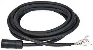


HT9Z-4PC110M-B
Stranded Cable Wire, Control Station, 10 m, HT4P Safety Commander Series
- Manufacturer: IDEC
- Product type: Industrial Switch Accessories
- SVHC: No SVHC (25-Jun-2025)
- For Use With: IDEC HT4P Safety Commander Series Control Station
- Product Range: HT4P Safety Commander Series
- Accessory Type: Stranded Cable Wire
| Delivery and price | |
|---|---|
| Units per pack | 1 |
| Price | 468.36 € |
| Current stock | 10+ |
| Lead time | 30 days |
## Tablet Mount Safety Device HT4P ## Safety Commander[™ ] Enable industrial tablets to provide operation safety Complies with safety requirements as required by the ISO 10218 series. ## Mechanical switches _NEW_ ~~-~~ • Up to 3 IDEC LB series switches can be installed. (*1) - Reliable operation. - Ideal for a wide range of applications. Complies with various standards. *1) The product will be shipped with requested switches. See P7 for custom products. Standard products Custom products (example) • Without mechanical switch • TS series joystick Custom products (example) • Illuminated pushbuttons (red) • Illuminated pushbuttons (green) • Key selector switch ~~==~~ ❚ E-stop switch with LED indicator Equipped with a safety lock mechanism, safe break action structure, and direct opening action. ## USB/LAN converter with built-in USB power delivery - Wired LAN enables stable communication regardless of the environment. - USB power delivery allows battery charge via USB while communicating. No need to worry about the battery running out. **==> picture [20 x 8] intentionally omitted <==** **----- Start of picture text -----**<br> NEW<br>**----- End of picture text -----**<br> ❚ Newly available with an emergency stop switch _NEW_ (button color: white, illuminated color: red) compliant with ISO 13850:2015 ) In addition to IDEC’s unique features, such as "Safety lock mechanism" and "Reverse energy structure", the illuminated E-stop switch allows intuitive visibility of the active/inactive status. Inactive (Non-illuminated) Active (Illuminated) Inactive (Non-illuminated) Active (Illuminated) (accessory) **HT4P** © a Mechanical Wired LAN 10 to 13 inches switch - ❚ Emergency stop switch guard (accessory) Retrofittable guards available. High performance 10 to 13 inches ❚ Safety device easily attaches to a _NEW_ 10- to 13-inch tablet - ❚ Vertical and horizontal operation for flexible use Ergonomic design for improved operability - The tablet can be readily equipped with a safety device. - Rotating grips allow the tablet to be used in vertical The tablet can be readily equipped with a safety device. or horizontal orientation. The emergency stop switch, which must be accessed instantly, can also be positioned for ease of use. + - • Easy to hold and operate, regardless of handedness. The ergonomic holder design and enabling switch position result in ease of holding and operability. Tablet - • Equipped with slide mechanism. • Fits large and rugged tablets. - valrp Vertical - left-hand use - QF, DM Horizontal Horizontal 10 inches 13 inches - right-hand use left-hand use **==> picture [169 x 53] intentionally omitted <==** **----- Start of picture text -----**<br> +<br>Tablet HT4P Safety Commander™<br>**----- End of picture text -----**<br> 2 Note: ISO 10218 series specifies the requirement for the installation of Note.) Excludes operation of enable switches. the three-position enabling switch on the teaching pendant. ## ❚ Three-position enabling switch Safety during work operations is assured by the ergonomically designed three-position action to avoid danger. _NEW_ ❚ Rotation unlock button Allows the grip to rotate only when the button is pressed, preventing unintentional rotation. - ❚ Hand strap or shoulder strap (accessories) ## ❚ Can be used set down Enables stable operation while placed on a desk. ❚ Rugged construction with drop resistance of 1.2m Designed for assurance, the product has passed drop tests assuming accidental drop or impact while carrying. (*) *) Drop resistance has been tested for tablet weights up to 1.1 kilogram. 1.2m Note: Drop protection of the product or tablet is not guaranteed. - Prevents the product from dropping during hand-held operation. - Reduces the burden when working long hours. ## ❚ IP54 protection Usable even in dusty environments or when exposed to splashing or spraying. - The shoulder strap has a safety feature that disengages when a certain load is applied. ## Safety Commander[™] Patent pending ## ❚ Expansion lock Prevents unintentional removal of the tablet. ❚ Expansion lock lever Locks the extension of the tablet holder. ## _NEW_ . ❚ Movable mounting hooks & spacers _NEW_ _NEW_ - ❚ Waterproof connector/ Wired LAN, switch contact, power supply cable (accessories) - Connector allows one-touch connection and disconnection of the cable. - Easy maintenance. The power and audio buttons on the tablet can be operated when mounted, as bracket and spacer positions can be changed. - Mounting bracket position can be changed. - Mounting spacer position can be changed. ❚ Wall mount Wall mount bracket (accessory) enables operation while fixed to the wall. Note: Only for operations that do not require an enabling switch. 3 Customer benefits ## Improved safety of tablets Eliminates the need to develop a dedicated device ## **BEFORE** - ❚ Devices can be controlled by only using tablets. - ❚ Safety is not ensured without safety devices. - ❚ Does not satisfy safety standards. ## **BEFORE** - ❚ Large development and production costs. - ❚ Difficult to handle discontinuation of parts. ❚ Complex operation due to too many buttons. - ❚ Wireless features are affected by noise. ## **AFTER** - ❚ Improved safety with safety devices. - ❚ Complies with international safety standards. - ❚ Wired LAN enables safe communication. ## **AFTER** - ❚ No hardware development required. Software only. - ❚ Low cost. - ❚ Easy to operate. ## Replacement for a touch panel on a control panel **BEFORE** Tl ❚ Individual touch panels are installed on multiple panel boards. ## **AFTER** Sa - ❚ One Safety Commander can be used in multiple locations. ❚ Cost reduction and space saving of control panel. ❚ Reduced number of touch panels. Enables operation close to the machine - **BEFORE** - | ❚ Fixed touch panels are used to control large machines. ❚ Multiple workers call out to each other during maintenance. ## **AFTER** Lg - ❚ By using the product together with a fixed touch panel, machines can be operated using the web browser and remote desktop functions. - ❚ Workers can operate close to the machine and the number of workers can be reduced. **==> picture [43 x 15] intentionally omitted <==** **----- Start of picture text -----**<br> Web browser or<br>remote desktop<br>**----- End of picture text -----**<br> 4 ## Applications 5 ## HT4P Safety Commander[™] |No.<br>Name<br>Description<br>(1) Emergency stop switch<br>XA1E-LV3SG02Q4R/<br>XA1E-LV3SG02Q4WR(IDEC)<br>(2) Enablingswitch<br>HE6B-M200Y(IDEC)<br>(3) Gripunit<br>Gripof theproduct<br>(4) Tablet holder unit<br>Secures the tablet<br>(5) Hook top<br>–<br>(6) Hook base<br>–<br>(7) Expansion lock lever<br>Extendable lever for tablet holder<br>(8) Expansion lock<br>Key lock for extendable lever<br>(includes2extendablelock releasekeys)<br>(9) Spacer<br>–<br>(10) USBport<br>Type-C<br>(11) Slide arm<br>–<br>(12) Hand strap<br>Supplied with theproduct<br>(13) Cable<br>Accessory (sold separately)<br>• See website for details on approvals and standards.<br>(1)<br>(10)<br>(11)<br>(5)<br>(2)<br>(3)<br>(4)<br>6)<br>(9)<br>(13)<br>(12)<br>(7)<br>(8)<br>cWAkus C€ CA<br>ess~~/o~~<br>~~Qk~~<br>)<br>~~-~~<br>(a|No.<br>Name<br>Description<br>(1) Emergency stop switch<br>XA1E-LV3SG02Q4R/<br>XA1E-LV3SG02Q4WR(IDEC)<br>(2) Enablingswitch<br>HE6B-M200Y(IDEC)<br>(3) Gripunit<br>Gripof theproduct<br>(4) Tablet holder unit<br>Secures the tablet<br>(5) Hook top<br>–<br>(6) Hook base<br>–<br>(7) Expansion lock lever<br>Extendable lever for tablet holder<br>(8) Expansion lock<br>Key lock for extendable lever<br>(includes2extendablelock releasekeys)<br>(9) Spacer<br>–<br>(10) USBport<br>Type-C<br>(11) Slide arm<br>–<br>(12) Hand strap<br>Supplied with theproduct<br>(13) Cable<br>Accessory (sold separately)<br>• See website for details on approvals and standards.<br>(1)<br>(10)<br>(11)<br>(5)<br>(2)<br>(3)<br>(4)<br>6)<br>(9)<br>(13)<br>(12)<br>(7)<br>(8)<br>cWAkus C€ CA<br>ess~~/o~~<br>~~Qk~~<br>)<br>~~-~~<br>(a|No.<br>Name<br>Description<br>(1) Emergency stop switch<br>XA1E-LV3SG02Q4R/<br>XA1E-LV3SG02Q4WR(IDEC)<br>(2) Enablingswitch<br>HE6B-M200Y(IDEC)<br>(3) Gripunit<br>Gripof theproduct<br>(4) Tablet holder unit<br>Secures the tablet<br>(5) Hook top<br>–<br>(6) Hook base<br>–<br>(7) Expansion lock lever<br>Extendable lever for tablet holder<br>(8) Expansion lock<br>Key lock for extendable lever<br>(includes2extendablelock releasekeys)<br>(9) Spacer<br>–<br>(10) USBport<br>Type-C<br>(11) Slide arm<br>–<br>(12) Hand strap<br>Supplied with theproduct<br>(13) Cable<br>Accessory (sold separately)<br>• See website for details on approvals and standards.<br>(1)<br>(10)<br>(11)<br>(5)<br>(2)<br>(3)<br>(4)<br>6)<br>(9)<br>(13)<br>(12)<br>(7)<br>(8)<br>cWAkus C€ CA<br>ess~~/o~~<br>~~Qk~~<br>)<br>~~-~~<br>(a|No.<br>Name<br>Description<br>(1) Emergency stop switch<br>XA1E-LV3SG02Q4R/<br>XA1E-LV3SG02Q4WR(IDEC)<br>(2) Enablingswitch<br>HE6B-M200Y(IDEC)<br>(3) Gripunit<br>Gripof theproduct<br>(4) Tablet holder unit<br>Secures the tablet<br>(5) Hook top<br>–<br>(6) Hook base<br>–<br>(7) Expansion lock lever<br>Extendable lever for tablet holder<br>(8) Expansion lock<br>Key lock for extendable lever<br>(includes2extendablelock releasekeys)<br>(9) Spacer<br>–<br>(10) USBport<br>Type-C<br>(11) Slide arm<br>–<br>(12) Hand strap<br>Supplied with theproduct<br>(13) Cable<br>Accessory (sold separately)<br>• See website for details on approvals and standards.<br>(1)<br>(10)<br>(11)<br>(5)<br>(2)<br>(3)<br>(4)<br>6)<br>(9)<br>(13)<br>(12)<br>(7)<br>(8)<br>cWAkus C€ CA<br>ess~~/o~~<br>~~Qk~~<br>)<br>~~-~~<br>(a|No.<br>Name<br>Description<br>(1) Emergency stop switch<br>XA1E-LV3SG02Q4R/<br>XA1E-LV3SG02Q4WR(IDEC)<br>(2) Enablingswitch<br>HE6B-M200Y(IDEC)<br>(3) Gripunit<br>Gripof theproduct<br>(4) Tablet holder unit<br>Secures the tablet<br>(5) Hook top<br>–<br>(6) Hook base<br>–<br>(7) Expansion lock lever<br>Extendable lever for tablet holder<br>(8) Expansion lock<br>Key lock for extendable lever<br>(includes2extendablelock releasekeys)<br>(9) Spacer<br>–<br>(10) USBport<br>Type-C<br>(11) Slide arm<br>–<br>(12) Hand strap<br>Supplied with theproduct<br>(13) Cable<br>Accessory (sold separately)<br>• See website for details on approvals and standards.<br>(1)<br>(10)<br>(11)<br>(5)<br>(2)<br>(3)<br>(4)<br>6)<br>(9)<br>(13)<br>(12)<br>(7)<br>(8)<br>cWAkus C€ CA<br>ess~~/o~~<br>~~Qk~~<br>)<br>~~-~~<br>(a| |---|---|---|---|---| |HT4P SafetyCommanderTM||||Quantity: 1| |Name<br>Tablet compatible size|Part No.||Emergency stop switch|Switch<br>Emergency stop switch<br>Mechanical switches(*1)| |HT4P Safety Commander™<br>Illuminated E-stop switch model<br>(button: red, illumination color: red)<br>HT4P-SLNPL<br>HT4P-SLSPL-R****|||XA1E-LV3SG02Q4R<br>(Button: red, illumination color: red)|–<br>•| |10 to 13 inches||||HE6B-M200Y| |HT4P Safety Commander™<br>Illuminated E-stop switch model<br>(button: white, illumination color: red)<br>HT4P-SLNPL-W<br>HT4P-SLSPL-W-R****|||XA1E-LV3SG02Q4WR<br>(Button: white, illumination color: red)|–<br>•| *1) See page 7 for details on models equipped with mechanical switches. |Name<br>~~i~~|Shape<br>~~.@~~|Specification<br>~~|.~~|Part No.<br>~~|.~~|Quantity<br>~~|.~~|Remarks<br>~~|.~~| |---|---|---|---|---|---| |Tablet thickness<br>adjustment kit A<br>~~i~~|~~.@~~|Spacer: aluminum<br>Rubber tube: rubber<br>~~|.~~|HT9Z-3PHB08<br>~~|.~~|1<br>~~|.~~|One pack contains 4 spacers and 4 rubber tubes.<br>Use with standard parts for tablet with thickness of 9 to 17mm.<br>~~|.~~| |Tablet thickness<br>adjustment kit B<br>~~i ~~<br>~~Ss~~<br>~~ee~~|~~.@~~<br>~~Ss~~<br>|Spacer: aluminum<br>Rubber tube: rubber<br>~~|.~~<br>~~[~~<br>|HT9Z-3PHB14<br>~~|.~~<br>~~[~~<br>~~Ff~~<br>|1<br>~~|.~~<br>~~Ff fo~~<br>|One pack contains 4 spacers and 4 rubber tubes.<br>Use with standard parts for tablet with thickness of 17 to 23mm.<br>~~|.~~<br>~~fo~~<br>| |Rubber tube<br>~~PIN;~~<br>~~ee~~|~~PIN;~~<br>|Rubber<br>~~PIN;~~<br>~~[~~<br>|HT9Z-3PHC10<br>~~PIN;~~<br>~~[~~<br>~~Ff~~<br>|1<br>~~PIN;~~<br>~~Ff fo~~<br>|For tablet thickness adjustment<br>Approx. 100mm (inside diameter ø6mm, external diameter ø9mm)<br>• Cut to length when aluminum spacers are provided by customer.<br>For details see the "12. Options/Maintenance parts" *16 and *17 on<br>the instruction sheet.<br>~~PIN;~~<br>~~fo~~<br>| |Shoulder strap<br>~~ee~~||PP, others<br>~~[~~<br>|HT9Z-4PS2<br>~~[~~<br>~~Ff~~<br>|1<br>~~Ff fo~~<br>|Shoulder strap<br>For safety reasons, if the strap holds more than a certain amount of<br>load, the strap will fall off.<br>~~fo~~<br>| |Cable (5m)<br>D-sub37p<br>~~eepe~~<br>~~aan~~|~~pe~~<br>~~aan~~|Double-shielded cable<br>25 cores<br>Power supply: AWG20<br>Ethernet: AWG26<br>Others: AWG28<br>~~[~~<br>~~pe~~<br>~~Se~~|HT9Z-4PC15MC-B<br>~~[~~<br>~~Ff~~<br>~~pe~~<br>~~es~~|1<br>~~Ff fo~~<br>~~pe~~|load, the strap will fall off.<br>D-sub37 pin (plug)<br>(mating screw: #4-40 inch screw)<br>~~fo~~<br>~~pe~~| |Cable stranded wire<br>~~pe~~<br>~~aan~~<br>~~fe,~~|~~pe~~<br>~~aan~~<br>~~fe, Se~~||HT9Z-4PC1*M-B<br>~~pe~~<br>~~es~~|1<br>~~pe~~|Stranded wire type, length (m)<br>* : 5 , 10, 15, 20<br>~~pe~~| |Emergency stop<br>switch<br>~~pe~~<br>~~aan~~<br>~~fe,~~<br>~~ee~~|~~pe~~<br>~~aan~~<br>~~fe, Se~~<br>~~ee~~|Plastic<br>~~pe~~<br>~~Se~~<br>~~es~~|HT9Z-4PG1<br>~~pe~~<br>~~es~~|1<br>~~pe~~|Screws for mounting emergency stop switch guards: Two M3 × 8 mm<br>countersunk tapping screws<br>~~pe~~| |Wall mount bracket<br>~~fe,~~<br>~~ee~~<br>~~we~~|~~fe, Se~~<br>~~ee~~<br>~~we~~|Aluminum<br>~~Se~~<br>~~es~~<br>|HT9Z-4PF1<br>|1<br>|The main unit can be fixed to a wall.<br>The mounting centers of the screws complies with VESA standard.<br>| |Hook (*2)<br>~~ee~~<br>~~we~~|~~ee~~<br>~~we~~|Hook top: Rubber<br>Hook base: Plastic<br>Spacer: Aluminum<br>Rubber tube: Rubber<br>~~es~~<br>|HT9Z-4PHZ<br>|1<br>|Hook to secure the tablet<br>(Hook top, hook base, 2 spacers (14mm) 2 rubber tubes (8mm), rivet)<br>| |Hook top (*2)<br>~~wea~~|~~wea~~|Rubber<br>~~a~~|HT9Z-4PHZ-F<br>~~a~~|1<br>~~a~~|Includes 2 pieces<br>~~a~~| - If the rivet is damaged, purchase the rivet from Hirosugi-Keiki, Part Number N-4060 6 HT4P Safety Commander™ ## Mechanical switch mount model (custom order) The following IDEC LB series mechanical switches can be installed on the HT4P as custom products. Quantity: 1 |Part No.|Emergency stop switch|Emergency stop switch|Mechanical switches|Mechanical switches|Mechanical switches|Mechanical switches| |---|---|---|---|---|---|---| ||XA1E-LV3SG02Q4R<br>(Button: red,<br>illumination color: red)|XA1E-LV3SG02Q4WR<br>(Button: white,<br>illumination color: red)|Mounting position|||Mounting image| ||||(1)|(2)|(3)|| |HT4P-SLSPL-R0001<br>~~Se.~~|•<br>~~Se.~~|–<br>~~Se.~~|–<br>~~Se.~~|–<br>~~Se.~~|Selector switch<br>2-position / 2NO contact /<br>maintained /<br>knob operator LB6S-2T2<br>~~Se.~~|~~Se.~~<br>~~.~~| |HT4P-SLSPL-W-R0001<br>~~Se.~~|–<br>~~Se.~~|•<br>~~Se.~~||||~~Se.~~<br>~~.~~| |HT4P-SLSPL-R0002<br>~~Se.~~<br>~~Sa~~|•<br>~~Se.~~<br>~~Sa~~|–<br>~~Se.~~<br>~~Sa~~|–<br>~~Se.~~<br>~~Sa~~|–<br>~~Se.~~<br>~~Sa~~|Selector switch<br>3-position / 2NO contact /<br>maintained /<br>knob operator LB6S-3T2<br>~~Se.~~<br>~~Sa~~|~~Se.~~<br>~~Sa~~<br>~~.~~| |HT4P-SLSPL-W-R0002<br>~~Sa~~|–<br>~~Sa~~|•<br>~~Sa~~||||~~Sa~~<br>~~.~~<br>~~°~~| |HT4P-SLSPL-R0003<br>~~Sa~~<br>~~eee~~|•<br>~~Sa~~<br>~~eee~~|–<br>~~Sa~~<br>~~eee~~|–<br>~~Sa~~<br>~~eee~~|–<br>~~Sa~~<br>~~eee~~|Key selector switch<br>2-position / 2NO contact /<br>maintained /<br>disk tumbler keyLB6K-2T2A<br>~~Sa~~<br>~~eee~~|~~Sa~~<br>~~.~~<br>~~eee~~<br>~~°~~| |HT4P-SLSPL-W-R0003<br>~~eee~~|–<br>~~eee~~|•<br>~~eee~~||||~~.~~<br>~~eee~~<br>~~°~~| |HT4P-SLSPL-R0004<br>~~eee~~<br>~~—~~|•<br>~~eee~~<br>~~—~~|–<br>~~eee~~<br>~~—~~|–<br>~~eee~~<br>~~—~~|–<br>~~eee~~<br>~~—~~|Key selector switch<br>3-position / 2NO contact /<br>maintained /<br>disk tumbler keyLB6K-3T2A<br>~~eee~~<br>~~—~~|~~eee~~<br>~~°~~<br>~~—~~| |HT4P-SLSPL-W-R0004<br>~~eee~~<br>~~—~~|–<br>~~eee~~<br>~~—~~|•<br>~~eee~~<br>~~—~~||||~~eee~~<br>~~°~~<br>~~—~~| |HT4P-SLSPL-R0005<br>~~—~~|•<br>~~—~~|–<br>~~—~~|Illuminated pushbuttons<br>Red / 1NO contact /<br>momentary LB6L-M1T14R<br>~~—~~|Illuminated pushbuttons<br>Green/1NO contact/<br>momentary LB6L-M1T14G<br>~~—~~|Key selector switch<br>3-position / 2NO contact /<br>maintained /<br>disk tumbler keyLB6K-3T2A<br>~~—~~|~~°~~<br>~~—~~| |HT4P-SLSPL-W-R0005|–|•||||~~°~~| |HT4P-SLSPL-R0006<br>~~eee~~|•<br>~~eee~~|–<br>~~eee~~|Illuminated pushbuttons<br>Red / 1NO contact /<br>momentary LB6L-M1T14R<br>~~eee~~|Illuminated pushbuttons<br>Green/1NO contact/<br>momentary LB6L-M1T14G<br>~~eee~~|Selector switch<br>2-position / 2NO contact /<br>maintained /<br>knob operator LB6S-2T2<br>~~eee~~|~~eee~~<br>~~°~~| |HT4P-SLSPL-W-R0006<br>~~eee~~|–<br>~~eee~~|•<br>~~eee~~||||~~eee~~<br>~~°~~| |HT4P-SLSPL-R0007<br>~~eee~~<br>~~eee~~|•<br>~~eee~~<br>~~eee~~|–<br>~~eee~~<br>~~eee~~|Illuminated pushbuttons<br>Green/1NO contact /<br>momentary LB6L-M1T14G<br>~~eee~~<br>~~eee~~|–<br>~~eee~~<br>~~eee~~|Key selector switch<br>3-position / 2NO contact /<br>maintained /<br>disk tumbler keyLB6K-3T2A<br>~~eee~~<br>~~eee~~|~~eee~~<br>~~°~~<br>~~eee~~| |HT4P-SLSPL-W-R0007<br>~~eee~~|–<br>~~eee~~|•<br>~~eee~~||||~~°~~<br>~~eee~~| |HT4P-SLSPL-R0008<br>~~eee~~|•<br>~~eee~~|–<br>~~eee~~|Illuminated pushbuttons<br>Green / 1NO contact /<br>momentary LB6L-M1T14G<br>~~eee~~|–<br>~~eee~~|Selector switch<br>2-position / 2NO contact /<br>maintained /<br>knob operator LB6S-2T2<br>~~eee~~|~~°~~<br>~~eee~~| |HT4P-SLSPL-W-R0008<br>~~eee~~|–<br>~~eee~~|•<br>~~eee~~||||~~eee~~| |HT4P-SLSPL-R0009<br>~~a:~~|•<br>~~a:~~|–<br>~~a:~~|Pushbuttons<br>White / 1NO contact /<br>momentary LB6B-M1T1W<br>~~a:~~|Pushbuttons<br>White / 1NO contact /<br>momentary LB6B-M1T1W<br>~~a:~~|Selector switch<br>2-position / 2NO contact /<br>maintained /<br>knob operator LB6S-2T2<br>~~a:~~|~~a:~~| |HT4P-SLSPL-W-R0009<br>~~a:~~|–<br>~~a:~~|•<br>~~a:~~||||~~a:~~| |HT4P-SLSPL-R0010<br>~~a:~~<br>~~Se.~~|•<br>~~a:~~<br>~~Se.~~|–<br>~~a:~~<br>~~Se.~~|Pushbuttons<br>Black /1NO contact/<br>momentary LB6B-M1T1B<br>~~a:~~<br>~~Se.~~|Illuminated pushbuttons<br>Green / 1NO contact/<br>momentary LB6L-M1T14G<br>~~a:~~<br>~~Se.~~|Selector switch<br>2-position / 2NO contact /<br>maintained /<br>knob operator LB6S-2T2<br>~~a:~~<br>~~Se.~~|~~a:~~<br>~~Se.~~| |HT4P-SLSPL-W-R0010<br>~~Se.~~|–<br>~~Se.~~|•<br>~~Se.~~||||~~Se.~~| 7 ~~EC~~ HT4P Safety Commander™ ## General specifications |Environmental Specifcations|Operating temperature (*3)|Operating temperature (*3)|-10 to +55°C<br>(when USB is not connected / product<br>is not held)<br>-10 to +40°C<br>(when connected to USB / product is<br>not held)<br>-10 to +35°C (*4)<br>(whenproductisheld) (nofreezing)||Structure Specifcation|Degree|Degree|ofprotection|IP54(*7)| |---|---|---|---|---|---|---|---|---|---| |||||||Co<br>ta||Compatible<br>tablet size|Tablet diagonal length :<br>290 to 380mm (270mm~ at reduced size)<br>Screen size: 10 to 13 inches| |||||||mpatible<br>blet (*8)||Compatible tablet<br>thickness|Standard : up to 9mm (*9)| |||||||||Compatible OS|(*11)| |||||||||Compatible<br>tablet weight|Max. 1.1kg (reference value)| ||Storage temperature||-20 to +55°C(no freezing)||||||| ||Storage humidity||30 to 85%RH(no condensation)|||<br>Weight (approx.) (*10)|||Approx. 880g<br>Approx. 2210g (Cable, including accessory<br>/ D-Sub type)| ||Operatinghumidity||30 to 85%RH(no condensation)||||||| ||Degree ofpollution||3||||||| |Electrical Specifcations<br>(*1)<br>(*2)|Rated insulation voltage||50V|||Gripunit rotation angle|||Approx. 120°(approx.)| ||Overvoltage category||II|||Housingcolor|||Black| ||Rated input voltage||Main power supply: 24V DC<br>(20.4V to 28.8V DC)||USB||Communication||USB 2.0 device<br>Highspeed (480Mbps)| ||||||||Power supply||USB PD Source<br>Output: 30W<br>5V-3A, 9V-3A, 15V-2A, 20V-1.5A| ||||Emergency stop switch<br>LED unit: 24V DC (21.6V to 26.4V DC)||||||| ||||<br>Mechanical switch LB series<br>LED unit: 24V DC (21.6V to 26.4V DC)||||||| ||||||||Cable||USB Type C connector<br>Cable length: 0.5m max.| ||Current draw||<br>Mainpower supply: 2.0A max.||||||| ||||||Ethernet<br>(*12)||Communication<br>method||<br>IEEE802.3i<br>10BASE-T, 100BASE-TX| ||||Emergency stop switch<br>LED unit: 11mA||||||| ||||||||Internal circuits and<br>insulation||<br>Pulse transformer| ||||Mechanical switch LB series<br>LED unit: 5mA||||||| ||||||Applicable standards||||IEC/EN 60947-5-1<br>IEC/EN 60947-5-5<br>(XA1E-LV3SG02Q4R, XA1E-LV3SG02Q4WR)<br>IEC/EN 60947-5-8(HE6B-M200Y)<br>UL 508<br>UL 60947-1<br>UL 60947-5-1<br>UL 60947-5-5<br>CSA C22.2 No.14| ||Allowable momentary power<br>interruption||1ms||||||| ||Dielectric strength||Main power supply 24V DC between<br>+/- terminals and FE terminal: 500V AC<br>for 1 min.||||||| ||Insulation resistance||Main power supply 24V DC between +/-<br>terminals and FE terminals: 100MΩ min.<br>(500V DC megger)||||||| ||Contact<br>ratings<br>(*5)|<br>Emergency stop switch (*6)<br>XA1E-LV3SG02Q4R<br>(Button: red, illumination<br>color: red)<br>XA1E-LV3SG02Q4WR<br>(Button: white, illumination<br>color: red)|2A / 30V DC (resistive load)<br>1A / 30V DC (inductive load)||||Safety standards||IEC/EN 61010-1<br>EN/IEC 61010-2-201| ||||||||Applicable<br>standards for use||ISO 12100<br>IEC 60204-1<br>ISO 10218-1<br>ISO 10218-2| |||<br>Enabling switch<br>HE6B-M200Y(*6)|1A / 30V DC (resistive load)<br>0.7A / 30V DC(inductive load)||||EMC standards||IEC/EN 61131-2| ||||||UL certifcation||||UL508<br>UL60947-5-5<br>CSA C22.2 No.14| |||Mechanical switch<br>LB series(*6)|0.1A / 30V DC (resistive load)||||||| |EMC<br>Specifcations||Immunity zone|Zone A (IEC/EN 61131-2)||||||| ||||||||||| |Mechanical<br>specifcation|Vibration resistance||5 to 8.4Hz: amplitude 3.5mm<br>8.4 to 150Hz : acceleration 9.8m/s2<br>(3 directions, 2 hours each)||||||| ||Shock resistance||147m/s211ms<br>(5 times each in 6 directions)||||||| - *1) If there is a risk of malfunction or destruction to the USB power supply or tablet due to noise from the connected power supply, use a dedicated USB power supply that is independent of other power supplies. Use Class2 or SELV power supply. This product does not support hot swap, so wiring should be done while the power supply to be connected is OFF. - *2) The emergency stop switch and LB series mechanical switch has a built-in current limiting resistor and a rectifier circuit. - *3) When using the product under operating temperature of more than 40oC, follow the instructions mentioned in "4. Specifications" *13 on the instruction sheet. - *4) The tablet holder unit generates heat when power is supplied for a long period of time. Do not supply power while holding the tablet holder unit for a long period of time as it may cause low-temperature burns. - *5) Specifications for components. - *6) UL certified rating Emergency stop switch / Enabling switch: 30VDC / 1A max. (Res), 30V / 0.7A max. (Pilot Duty) Mechanical switch: 30V / 0.1A max. (Res) - *7) Not when USB cable is connected. - *8) May not be applicable depending on the shape. Weight is not guaranteed. - *9) Tablet thickness can be adjusted up to 23mm with the accessory tablet thickness adjustment kit. Use HT9Z-3PHB08 for tablet thickness of 9mm to 17mm and HT9Z-3PHB14 for tablet thickness of 17mm to 23mm by adding them to the standard parts. - *10) Except hand straps and other accessories. - *11) See "USB to Ethernet Conversion Function" below for details. - *12) USB to Ethernet Conversion Function USB-Ethernet conversion function can be used by installing a dedicated software driver on a Windows tablet. This function is available using MAXLINEAR's dedicated IC (model number: XR22801). The dedicated software driver can be downloaded from the MAXLINEAR website below and should be used in accordance with the conditions of use described on the website. Check the following website for supported OS and versions. https://www.maxlinear.com/support/design-tools/software-drivers Before using the software, check the Errata information from the following website and handle the software according to the information. https://www.maxlinear.com/product/interface/bridges/usb-ethernet-bridges/xr22801#documentation 8 HT4P Safety Commander™ ## Dimensions All dimensions in mm. Main parts **==> picture [293 x 407] intentionally omitted <==** **----- Start of picture text -----**<br> Emergency stop switch<br>Part no.: XA1E-LV3SG02Q4R/ Enabling switch<br> XA1E-LV3SG02Q4WR (IDEC) Part no.: HE6B-M200Y(IDEC)<br>259 133<br>113<br>USB port<br>(Type-C)<br>Spacer<br>Minimum expansion<br>334<br>Minimum expansion<br>239<br>291<br>**----- End of picture text -----**<br> **==> picture [48 x 47] intentionally omitted <==** **==> picture [228 x 139] intentionally omitted <==** **----- Start of picture text -----**<br> Tablet holder unit<br>Connector<br>Part no. :RTS716N26P03<br> (Amphenol Corp.)<br>Expansion lock<br>Grip unit<br>Lock lever<br>Slide arm<br>**----- End of picture text -----**<br> 9 HT4P Safety Commander™ |HT4P side<br>connector code<br>~~Pot~~<br>~~cr~~|Cable core<br>color (*1)<br>~~Pot~~<br>~~|~~<br>~~cr~~|D-sub37p<br>pin no. (*2)|Function<br>name|HT4P-SLNPL<br>HT4P-SLNPL-W<br>(Standard)|HT4P-SLSPL-R*<br>HT4P-SLSPL-W-R*<br>(Mechanical switch installed)| |---|---|---|---|---|---| |A<br>~~Pot~~<br>~~cr~~|Black<br>~~Pot~~<br>~~|~~<br>~~cr~~|1|Main power<br>supply<br>~~ee~~|24V DC+|24V DC| |B<br>~~Pot~~<br>~~cr~~<br>~~ee~~|White<br>~~Pot~~<br>~~|~~<br>~~cr~~<br>~~ee~~<br>~~ee~~|2<br>~~ee~~<br>~~ee~~||24V DC-<br>~~ee~~|24V DC<br>~~ee~~| |C<br>~~Pot~~<br>~~cr~~<br>~~ee~~<br>~~a~~<br>~~Se~~|Shield<br>(External/Internal)<br>~~Pot~~<br>~~|~~<br>~~cr~~<br>~~ee~~<br>~~ee~~<br>~~ee~~<br>~~ee~~|21<br>~~ee~~<br>~~ee~~<br>~~ee~~||FE terminal<br>~~ee~~<br>~~ee~~<br>~~ee~~|FE terminal<br>~~ee~~| |D<br>~~cr~~<br>~~a~~<br>~~Se~~|Blue<br>~~cr~~<br>~~ee~~<br>~~ee~~<br>~~ee~~|5<br>~~ee~~<br>~~ee~~|Ethernet<br>~~ee~~<br>~~ee~~<br>~~ee~~|TPO +(sent data +)<br>~~ee~~<br>~~ee~~<br>~~ee~~|TPO +(sent data +)<br>~~ee~~| |D<br>E<br>~~a~~<br>~~Se~~|White/Blue<br>~~ee ~~<br>~~ee~~<br>~~ee~~|6<br> ~~ee~~<br>~~ee~~||TPO +(sent data +)<br>TPO-(sent data -)<br>~~ee~~<br>~~ee~~<br>~~ee~~|TPO +(sent data +)<br>TPO-(sent data-)<br>~~ee~~| |F<br>~~a~~<br>~~Se~~<br>~~ee~~|Orange<br>~~ee~~<br>~~ee~~<br>~~ee~~|7<br>~~ee~~<br>~~ee~~||TPI +(received data +)<br>~~ee~~<br>~~ee~~<br>~~ee~~|TPI +(received data +)| |F<br>G<br>~~Se ~~<br>~~ee~~<br>~~a~~|g<br>White/Orange<br> ~~ee~~<br>~~ee~~<br>~~ee~~|8<br>~~ee~~<br>~~ee~~<br>~~ee~~||TPI +(received data +) <br>TPI-(received data -)<br>~~ee~~<br>~~ee~~<br>~~ee~~|TPI +(received data +)<br>TPI-(received data -)| |H<br>~~ee~~<br>~~a~~<br>~~==S~~|Blue<br>~~ee ~~<br>~~ee~~<br>~~==S~~|11<br> ~~ee~~<br>~~ee~~<br>~~==S~~|Mechanical<br>switch<br>~~ee~~<br>~~ee~~<br>~~ee~~<br>~~ee~~<br>~~ee~~<br>~~ee~~|-<br>~~ee~~<br>~~ee~~|Switch(NO1)| |J<br>~~a~~<br>~~==S~~|Gray<br>~~ee~~<br>~~==S~~|12<br>~~ee~~<br>~~==S~~||-<br>~~ee~~|Switch (COM1)| |K<br>~~==S~~<br>~~ee~~|Orange<br>~~==S~~<br>~~ee~~|13<br>~~==S~~<br>~~ee~~||-<br>~~es~~|Switch (NO2)<br>~~es~~| |L<br>~~ee~~<br>~~ee~~|Purple<br>~~ee~~<br>~~ee~~|14<br>~~ee~~<br>~~ee~~||-<br>~~es~~<br>~~es~~|Switch (COM2)<br>~~es~~<br>~~es~~| |M<br>~~ee~~<br>~~ee~~<br>~~ee~~|Pink<br>~~ee~~<br>~~ee~~<br>~~ee~~|15<br>~~ee~~<br>~~ee~~<br>~~ee~~||-<br>~~es~~<br>~~es~~<br>~~ee~~|Switch (NO1)<br>~~es~~<br>~~es~~<br>~~ee~~| |N<br>~~ee~~<br>~~ee~~<br>~~ee~~|Light blue<br>~~ee~~<br>~~ee~~<br>~~ee~~|16<br>~~ee~~<br>~~ee~~<br>~~ee~~||-<br>~~es~~<br>~~ee~~<br>~~es~~|Switch (NO1)<br>~~es~~<br>~~ee~~<br>~~es~~| |P<br>~~ee ~~<br>~~ee~~<br>~~ee~~|White/Red<br> ~~ee~~<br>~~ee~~<br>~~ee~~|17<br>~~ee~~<br>~~ee~~||-<br>~~ee~~<br>~~es~~<br>~~es~~|For switch LED (24V DC)<br>~~ee~~<br>~~es~~<br>~~es~~| |R<br>~~ee~~<br>~~ee~~<br>~~ee~~|White/Green<br>~~ee~~<br>~~ee~~|18<br>~~ee~~||-<br>~~es~~<br>~~es~~<br>~~ee~~|For switch LED (24V DC)<br>~~es~~<br>~~es~~<br>~~ee~~| |S<br>~~ee~~<br>~~ee~~<br>~~ee~~<br>~~Po~~|White/Yellow<br>~~ee~~<br>~~ee~~<br>~~Po~~|19||-<br>~~es~~<br>~~ee~~<br>~~ee~~|Switch · LED commonCOM<br>~~es~~<br>~~ee~~<br>~~ee~~| |T<br>~~ee~~<br>~~ee~~<br>~~ee~~<br>~~Po~~|White/Brown<br>~~ee~~<br>~~ee~~<br>~~Po~~|27|Emergency<br>stop switch<br>~~ee~~|LED(X1)<br>~~ee~~<br>~~ee~~<br>~~ee~~|LED(X1)<br>~~ee~~<br>~~ee~~<br>~~ee~~| |U<br>~~ee ~~<br>~~ee~~<br>~~ee~~<br>~~Po~~|White/Blue<br> ~~ee~~<br>~~ee~~<br>~~ee~~<br>~~Po~~|28<br>~~ee~~||LED(X2)<br>~~ee~~<br>~~ee~~<br>~~es~~|LED(X2)<br>~~ee~~<br>~~ee~~<br>~~es~~| |V<br>~~ee~~<br>~~ee~~<br>~~ee~~<br>~~Po~~|White/Gray<br>~~ee~~<br>~~ee~~<br>~~ee~~<br>~~Po~~|29<br>~~ee~~||Contact 1(NC)<br>~~ee~~<br>~~es~~<br>~~es~~|Contact 1(NC)<br>~~ee~~<br>~~es~~<br>~~es~~| |W<br>~~ee ~~<br>~~ee~~<br>~~Po~~|White/Orange<br> ~~ee~~<br>~~ee~~<br>~~Po~~|30<br>~~ee~~||Contact 1(NC)<br>~~es~~<br>~~es~~|Contact 1(NC)<br>~~es~~<br>~~es~~| |X<br>~~ee~~<br>~~Po~~|White/Purple<br>~~ee~~<br>~~Po~~|31||Contact 2(NC)<br>~~es~~|Contact 2(NC)<br>~~es~~| |Y<br>~~Po~~<br>~~a~~<br>~~ee~~|White/Pink<br>~~Po~~<br>~~ee~~|32||Contact 2(NC)<br>~~ee~~<br>~~es~~|Contact 2(NC)<br>~~ee~~<br>~~es~~| |Z<br>~~Po~~<br>~~ee~~<br>~~ee~~<br>~~es~~|Red<br>~~Po~~<br>~~ee~~<br>~~ee~~|33|Enabling<br>switch<br>~~7~~<br>~~ee~~|Contact 1(COM)<br>~~es~~<br>~~ee~~|Contact 1(COM)<br>~~es~~<br>~~ee~~| |a<br>~~ee~~<br>~~ee~~<br>~~es~~|Green<br>~~ee~~<br>~~ee~~|34||Contact 1(NO)<br>~~es~~<br>~~ee~~|Contact 1(NO)<br>~~es~~<br>~~ee~~| |b<br>~~ee~~<br>~~es~~|Yellow<br>~~ee~~<br>~~ee~~|35<br>~~ee~~||Contact 2(COM)<br>~~ee~~<br>~~ee~~|Contact 2(COM)<br>~~ee~~<br>~~ee~~| |c<br>~~es~~|Brown<br>~~ee~~|36<br>~~ee~~||Contact 2(NO)<br>~~ee~~|Contact 2(NO)<br>~~ee~~| When preparing cables by the customer - 1) Cables smaller than AWG20 cannot be connected to the main power supply. Use cables larger than AWG20. - 2) Use cables with transmission characteristics equivalent to LAN cables of Category 5 or higher for Ethernet wiring, and shield the entire Ethernet cable with a shield. (Internal shield) - 3) In addition to the cables for the main power supply, the emergency stop switch and enabling switch, and the entire shielded Ethernet cable should be further shielded. - *1) Stranded wire core color for option cable HT9Z-4PC1*M-B. - *2) D-sub37p connector pin number for option cable HT9Z-4PC15MC-B. ## System configuration - •Wiring not available for pin number 3, 4, 9, 10, 20, 22 to 26 and 37. **==> picture [542 x 312] intentionally omitted <==** **----- Start of picture text -----**<br> HT4P Safety Commander™ Cable Controller<br>External shield<br>Emergency stop switch<br>LED Emergency stop switch<br>LED signal x 1<br>Emergency stop switch contact Emergency stop switch<br>contact signal x 2<br>Enabling switch Enabling switch<br>contact signal x 2<br>[<br>Mechanical switch (SW ) Mechanical switch LED signal ×2 (Max.)<br> contact signal × 2 (Max.)<br>Mechanical switch (SW ) Independent contact signal × 2<br>Internal shield<br>USB/LAN converter & Ethernet<br>USB Power Delivery<br>Main power supply Main power supply<br>FE terminal 3) Connect both the internal<br>(*3) (*4) shield and external shield to<br>the FE terminal.<br>4) Connect both the internal<br>shield and external shield<br>USB<br>Type-C to FE.<br>FE<br>Tablet<br>USB communication / power supply<br>a Safety Precautions a aaa<br>• Turn off the power to the product before starting installation, removal, wiring, maintenance, or inspection. Failure to turn power off may cause<br>electrical shock or fire.<br>**----- End of picture text -----**<br> ## Instructions ~~|~~ Be sure to read the instruction manual carefully before performing installation, wiring, or maintenance work. For details on mounting, wiring, and maintenance, see the instruction manual from the below URL. URL: https://product.idec.com/?product=HT4P https://product.idec.com/?product=HT4P-LB **==> picture [105 x 14] intentionally omitted <==** **----- Start of picture text -----**<br> HT4P HT4P mechanical<br>switch mount model<br>**----- End of picture text -----**<br> 10 ~~DEC~~ HT3P Safety Commander™ ## **HT3P** ## Lightweight, basic type 8 to 11 inches (Patent pending) ## ❚[Fits 8- to 11-inch tablets] The adjustable docking structure fits screen sizes of 8 to 11 inches. Safety Commander™ can also be attached to tablets with thicknesses of up to 24mm (*1) by using a spacer accessory. Thick and robust tablets can also be mounted. - *1) Standard thickness: up to 10mm. When accessory "tablet thickness adjustment kit A" is used: up to 18mm. When accessory "tablet thickness adjustment kit B" is used: up to 24mm Screen size: Thickness: 8 to 11 inches up to 24mm ## ❚[E-stop switch with LED indicator] Equipped with a safety lock mechanism, safe break action structure, and direct opening action. ❚[ Newly available with an emergency stop switch ] _NEW_ (button color: white, illuminated color: red) compliant with ISO 13850:2015 ) © In addition to IDEC’s unique features, such as "Safety lock mechanism" and "Reverse energy structure", the illuminated E-stop switch allows intuitive visibility Inactive (Non-illuminated) Active (Illuminated) of the active/inactive status. ## ❚[Rotating holder] Ease of holding and operability. Adapts to both vertical and horizontal use. Horizontal Vertical Horizontal right-hand use left-hand use left-hand use ## ❚[Three-position enabling switch] Safety during work operations is assured by the ergonomically designed three-position action to avoid danger. Note: ISO 10218 series specifies the requirement for the installation of the three-position enabling switch on the teaching pendant. ## ❚[USB charging port] No need to worry about the battering running out while communicating. Note: 5V DC-1.5A output ## ❚[Wall mount] Wall mount bracket (accessory) enables operation while fixed to the wall Note: Only for operations that do not require an enabling switch. ## ❚[Expansion lock] Prevents unintentional removal of the tablet. ## ❚[Expansion lock lever] 5m cable supplied (with nylon connector terminal) Locks the tablet holder from extending. ❚[Product] Quantity: 1 ❚[System configuration] Item Part No. HT3P Safety Commander™ Cable Contact ~~a~~ HT3P Safety Commander[TM] Emergency Stop ~~ho~~ Illuminated E-stop switch model (button: red, illumination color: red)[HT3P-SLNP-5M] SW 24V DC LED HT3P Safety Commander[TM] HT3P-SLNP-5M-W Illuminated E-stop switch model (button: white, illumination color: red) Enabling Contact SW ❚[Specification] 24V DC Controller Item Specification ~~ee a~~ Structure Degree of Protection IP54 USB power (7.5w) Compatible tablet size 8 to 11inch Emergency stop switch XA1E-LV3SG02Q4R/ XA1E-LV3SG02Q4WR (IDEC) Switch Enabling switch HE5B-M2PY (IDEC) Type-CUSB Tablet USB port: Type-C Power USB power supply ~~AL~~ USB power supply 7.5w External cable connection method 5m cable supplied 11 HT4P Safety Commander™ ## Ordering Terms and Conditions ## Thank you for using IDEC Products. By purchasing products listed in our catalogs, datasheets, and the like (hereinafter referred to as “Catalogs”) you agree to be bound by these terms and conditions. Please read and agree to the terms and conditions before placing your order. ## 1. Notes on contents of Catalogs - (1) Rated values, performance values, and specification values of IDEC products listed in this Catalog are values acquired under respective conditions in independent testing, and do not guarantee values gained in combined conditions. - Also, durability varies depending on the usage environment and usage conditions. - (2) Reference data and reference values listed in Catalogs are for reference purposes only, and do not guarantee that the product will always operate appropriately in that range. - (3) The specifications / appearance and accessories of IDEC products listed in Catalogs are subject to change or termination of sales without notice, for improvement or other reasons. - (4) The content of Catalogs is subject to change without notice. ## 2. Note on applications - (1) If using IDEC products in combination with other products, confirm the applicable laws / regulations and standards. - Also, confirm that IDEC products are compatible with your systems, machines, devices, and the like by using under the actual conditions. IDEC shall bear no liability whatsoever regarding the compatibility with IDEC products. - (2) The usage examples and application examples listed in Catalogs are for reference purposes only. Therefore, when introducing a product, confirm the performance and safety of the instruments, devices, and the like before use. Furthermore, regarding these examples, IDEC does not grant license to use IDEC products to you, and IDEC offers no warranties regarding the ownership of intellectual property rights or non-infringement upon the intellectual property rights of third parties. - (3) When using IDEC products, be cautious when implementing the following. i. Use of IDEC products with sufficient allowance for rating and performance - ii. Safety design, including redundant design and malfunction prevention design that prevents other danger and damage even in the event that an IDEC product fails - iii. Wiring and installation that ensures the IDEC product used in your system, machine, device, or the like can perform and function according to its specifications - (4) Continuing to use an IDEC product even after the performance has deteriorated can result in abnormal heat, smoke, fires, and the like due to insulation deterioration or the like. Perform periodic maintenance for IDEC products and the systems, machines, devices, and the like in which they are used. - (5) IDEC products are developed and manufactured as general-purpose products for general industrial products. They are not intended for use in the following applications, and in the event that you use an IDEC product for these applications, unless otherwise agreed upon between you and IDEC, IDEC shall provide no guarantees whatsoever regarding IDEC products. - i. Use in applications that require a high degree of safety, including nuclear power control equipment, transportation equipment (railroads / airplanes / ships / vehicles / vehicle instruments, etc.), equipment for use in outer space, elevating equipment, medical instruments, safety devices, or any other equipment, instruments, or the like that could endanger life or human health - ii. Use in applications that require a high degree of reliability, such as provision systems for gas / waterworks / electricity, etc., systems that operate continuously for 24 hours, and settlement systems ## 3. Inspections We ask that you implement inspections for IDEC products you purchase without delay, as well as thoroughly keep in mind management/maintenance regarding handling of the product before and during the inspection. ## 4. Warranty - (1) Warranty period The warranty period for IDEC products shall be one (1) year after purchase or delivery to the specified location. However, this shall not apply in cases where there is a different specification in the Catalogs or there is another agreement in place between you and IDEC. - (2) Warranty scope Should a failure occur in an IDEC product during the above warranty period for reasons attributable to IDEC, then IDEC shall replace or repair that product, free of charge, at the purchase location / delivery location of the product, or an IDEC service base. However, failures caused by the following reasons shall be deemed outside the scope of this warranty. - i. The product was handled or used deviating from the conditions / environment listed in the Catalogs - ii. The failure was caused by reasons other than an IDEC product - iii. Modification or repair was performed by a party other than IDEC - iv. The failure was caused by a software program of a party other than IDEC - v. The product was used outside of its original purpose - vi. Replacement of maintenance parts, installation of accessories, or the like was not performed properly in accordance with the user’s manual and Catalogs - vii. The failure could not have been predicted with the scientific and technical standards at the time when the product was shipped from IDEC - viii. The failure was due to other causes not attributable to IDEC (including cases of force majeure such as natural disasters and other disasters) - Furthermore, the warranty described here refers to a warranty on the IDEC product as a unit, and damages induced by the failure of an IDEC product are excluded from this warranty. ## 5. Limitation of liability The warranty listed in this Agreement is the full and complete warranty for IDEC products, and IDEC shall bear no liability whatsoever regarding special damages, indirect damages, incidental damages, or passive damages that occurred due to an IDEC product. ## 6. Service scope The prices of IDEC products do not include the cost of services, such as dispatching technicians. Therefore, separate fees are required in the following cases. - (1) Instructions for installation / adjustment and accompaniment at test operation (including creating application software and testing operation, etc.) - (2) Maintenance inspections, adjustments, and repairs - (3) Technical instructions and technical training - (4) Product tests or inspections specified by you The above content assumes transactions and usage within your region. Please consult with an IDEC sales representative regarding transactions and usage outside of your region. Also, IDEC provides no guarantees whatsoever regarding IDEC products sold outside your region. - iii. Use in applications where the product may be handled or used deviating from the specifications or conditions / environment listed in the Catalogs, such as equipment used outdoors or applications in environments subject to chemical pollution or electromagnetic interference If you would like to use IDEC products in the above applications, be sure to consult with an IDEC sales representative. **Head Office** 6-64, Nishi-Miyahara-2-Chome, Yodogawa-ku, Osaka 532-0004, Japan **USA** IDEC Corporation **Singapore** IDEC Izumi Asia Pte. Ltd. **EMEA** APEM SAS **Thailand** IDEC Asia (Thailand) Co., Ltd. **India** IDEC Controls India Private Ltd. Specifications and other descriptions in this brochure are subject to change without notice. Information in this brochure is current as of September, 2025. 2025 IDEC Corporation, All Rights Reserved. **China Taiwan** ## **www.idec.com** IDEC (Shanghai) Corporation **Japan** IDEC Corporation IDEC Hong Kong Co. Ltd. IDEC Taiwan Corporation **==> picture [95 x 33] intentionally omitted <==** EP1791-11 12
Updated at April 23, 2026
Founded in 1945, IDEC is a globally recognized leader in industrial automation, machine safety, and control products. Renowned for pioneering innovations in Human-Machine Interface (HMI) systems, the company is dedicated to creating a safe and efficient harmony between advanced workplace technology and human operators. At the core of IDEC’s extensive portfolio is a comprehensive selection of high-performance relays designed for demanding industrial environments. This includes a broad range of electromechanical power relays, solid-state relays, contactors, and critical safety relays, supported by a wide array of specialized relay accessories to ensure reliable and efficient switching. Beyond switching components, IDEC provides complete solutions for modern control panels and automated systems. Their robust engineering extends to advanced panel displays and instrumentation, precision light sensors, and dependable AC/DC power converters. With additional offerings in industrial switches, visual signaling units, and DIN rail terminal blocks, IDEC equips engineers with the high-quality components required to build secure, next-generation automation infrastructure.
About Novapart
Novapart is a B2B electronic component broker specialising in stock shortages and cost reduction. We source hard-to-find parts and identify compliant alternatives across a catalogue of 410,000+ components from 500+ manufacturers.
Learn more →Stock Shortage Specialist
When a component is unavailable, discontinued or has an unacceptable lead time, we tap into our network of vetted European and Asian distributors to source what you need — without compromising on quality or traceability.
Request a quote →Compliant Alternatives
We identify pin-to-pin, electrically equivalent substitutes that meet the same certifications (RoHS, AEC-Q100, REACH) as your original specification — validated against datasheets, not just part numbers. Often at a lower cost.
BOM Analysis service →