
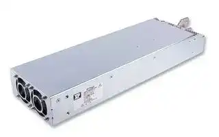


HPU1K5PS48-M
AC/DC Enclosed Power Supply (PSU), ITE, 1 Outputs, 1.5 kW, 48 VDC, 31 A
- Manufacturer: XP POWER
- Product type: AC / DC Enclosed Power Supplies
- No. of Outputs:1Outputs; Output Power Max:1.5kW; Output Voltage - Output 1:48V; Output Current - Output 1:31A; Output Voltage - Output 2:-; Output Current - Output 2:-; Output Volt
- SVHC: No SVHC (15-Jan-2018)
- Product Range: HPU1K5 Series
- No. of Outputs: 1Outputs
- Output Power Max: 1.5kW
- Input Voltage VAC: 85V AC to 264V AC
- Input Voltage AC Max: 264V
- Input Voltage AC Min: 85V
- Power Supply Output Type: Fixed
- Output Current - Output 1: 31A
- Output Current - Output 2: -
- Output Current - Output 3: -
- Output Current - Output 4: -
- Output Voltage - Output 1: 48VDC
- Output Voltage - Output 2: -
- Output Voltage - Output 3: -
- Output Voltage - Output 4: -
- Power Supply Applications: ITE
| Delivery and price | |
|---|---|
| Units per pack | 1 |
| Price | 925.65 € |
| Current stock | 10+ |
| Lead time | 30 days |
HPU1K5 series

## 1.5kW **Fancooled**

**AC-DC power supplies**

The HPU1K5 is a low profile 15kW AC-DC power supply with high power density that is designed for use in a wide range of industrial electronics and medical applications. The HPU1K5 delivers 1.2kW at Low Line and 1.5kW at High Line with three output models 12V, 24V & 48VDC.

The HPU1K5 is supplied with a range of signals and control, self cooling via integral fans and customer mounting options on three faces making it suitable for a variety of enclosures and applications where status reporting and control functions are increasingly required.

## **Features**

## **Applications**

## **Dimensions**

- f 1.5kW high line 1.2kW low line fan cooled

323.9 x 101.6 x 43.2mm (12.75” x 4.00” x 1.70”)

- f Single phase input 85 to 264VAC

- f Regulated single outputs 12V, 24V & 48VDC

- f Medical safety approvals (-M versions)

- f Variable fan speed to reduce audible noise

- f AC OK, DC OK & inhibit

- f Fault & overtemperature signals

- f SEMI F47 compliant

**==> picture [140 x 16] intentionally omitted <==**

**----- Start of picture text -----**<br>
Healthcare Industrial  Semiconductor<br>electronics manufacturing<br>**----- End of picture text -----**<br>


Technology

**==> picture [152 x 73] intentionally omitted <==**

**----- Start of picture text -----**<br>
Documentation<br>Ld<br>For further information click the link or scan<br>the code<br>xppower.com<br>**----- End of picture text -----**<br>


- f 5VDC standby

- f -20°C to +70°C operation

- f 3 year warranty

## **Models & ratings**

|Model number(1)|Output power(2)|Output voltage V1|Voltage Adjust V1|Output current V1|Output current V1|Standby Supply V2|
|---|---|---|---|---|---|---|
|||||<180VAC|>180VAC||
|HPU1K5PS12|1.2kW|12.0VDC|11-14VDC|100A|100A|5VDC/1A|
|HPU1K5PS24|1.5kW|24.0VDC|22-28VDC|50A|63A|5VDC/1A|
|HPU1K5PS48|1.5kW|48.0VDC|45-52VDC|25A|31A|5VDC/1A|


Notes: 1. For medical version, add suffix ‘-M’ to model number. 2. See derating curves.

1 [|

**AC-DC power supplies**

## HPU1K5 series

## **Input**

**==> picture [554 x 21] intentionally omitted <==**

**----- Start of picture text -----**<br>
Characteristic Minimum Typical Maximum Units Notes & conditions<br>**----- End of picture text -----**<br>


|Characteristc|Minimum|Typical|Maximum|Units|Notes & conditons|
|---|---|---|---|---|---|
|||||||
|Input voltage|85||264|VAC|See derating curve|
|Input frequency|47||63|Hz||
|Power factor||>0.9||||
|Input current||13/6.5||A|115/230VAC|
|Inrush current||35||A|264VAC|
|Earth leakage current|||1.1|mA|264VAC, 60Hz|
||||<300|µA|264VAC (-M version)|
|Input protection|Internal T20A/250 VAC fuse in line and neutral|||||


## **Output**

**==> picture [553 x 21] intentionally omitted <==**

**----- Start of picture text -----**<br>
Characteristic Minimum Typical Maximum Units Notes & conditions<br>**----- End of picture text -----**<br>


|Characteristc|Minimum|Typical|Maximum|Units|Notes & conditons|
|---|---|---|---|---|---|
|||||||
|Output voltage|See models and ratings table|||||
|Output voltage trim|Via potentiometer or external voltage, see model tables|||||
|Initial set accuracy||±1||%|Of nominal with 50% load|
|Minimum load|0|||A|No minimum load required|
|Start up delay||1||s||
|Line regulation|||±0.5|%||
|Load regulation|||±0.5|%|V1|
||||±5.0||V2|
|Transient response||4||%|Deviation recovery to within 2% in 500µs for 50-75-50% load change|
|Ripple & noise|||1|% max pk-pk|24-48V models, 20MHz bandwidth|
||||2||12V models, 20MHz bandwidth|
||||3||V standby, 20MHz bandwidth|
|Overvoltage protection|115||140|%|V1 nominal, recycle input|
|Overtemperature protection|Protects the unit against overtemperature, auto restart|||||
|Overcurrent protection|110||140|%|V1, V Standby power limited|
|Temperature coeffcient|||0.02|%/˚C|After 20 minute warm up|
|Short circuit protection|Continuous, trip and restart (hiccup mode)|||||
|Remote sense|Compensates for 0.5V total drop|||||
|Current share|Share upto 8 units maximum, units share current within 10% of each other at full load.|||||


## **General**

|Characteristc|Minimum|Typical|Maximum|Units|Notes & conditons|
|---|---|---|---|---|---|
|Effciency||90||%||
|Isolation:  Input to output<br>Input to ground<br>Output to ground|4000|||VAC|2 x MOPP|
||1500|||VAC|1 x MOPP|
||500|||VDC||
|Switching frequency||70||kHz|PFC|
|||130|||Main converter|
|Power density|||1.09 (18.0)|W/cm3(W/in3)||
|MTBF||470||khrs|Telecordia SR-332 at 25°C, GB|
|Signals|AC OK, DC OK, Inhibit, Fault at 25 °C, GB|||||


Specifications subject to change without notice.

2

**AC-DC power supplies**

## HPU1K5 series

## **Environmental**

**==> picture [554 x 17] intentionally omitted <==**

**----- Start of picture text -----**<br>
Characteristic Minimum Typical Maximum Units Notes & conditions<br>**----- End of picture text -----**<br>


|Characteristc|Minimum|Typical|Maximum|Units|Notes & conditons|
|---|---|---|---|---|---|
|||||||
|Operating temperature|-20||+70|°C|Derate linearly from +50°C at 2.5%/°C to 50% load at +70°C|
|Cooling|Internal load dependant variable speed fans|||||
|Humidity||95||%RH|RH, non-condensing|
|Operating altitude|||3000|m||
|Shock|±3 shocks in each axis (total 18 shocks) 30 g 11 ms (half sine). Compliant with EN60068-2-27.|||||
|Vibration|2 g 10-500 Hz 10 sweeps. Compliant with EN60068-2-6.|||||


## **EMC: emissions**

**==> picture [554 x 17] intentionally omitted <==**

**----- Start of picture text -----**<br>
Phenomenon Standard Test level Notes & conditions<br>**----- End of picture text -----**<br>


|Phenomenon|Standard|Test level|Notes & conditons|
|---|---|---|---|
|||||
|Conducted|EN55011/EN55032|A||
|Radiated|EN55011/EN55032|A||
|Harmonic currents|EN61000-3-2|Class A|(Class C for loads ≥10%)|
|Voltage ficker|EN61000-3-3|||


## **EMC:  immunity**

**==> picture [554 x 17] intentionally omitted <==**

**----- Start of picture text -----**<br>
Phenomenon Standard Test level Criteria Notes & conditions<br>**----- End of picture text -----**<br>


|Phenomenon|Standard|Test level|Criteria|Notes & conditons|
|---|---|---|---|---|
||||||
|ESD immunity|EN61000-4-2|4|A||
|Radiated immunity|EN61000-4-3|3|A||
|EFT/Burst|EN61000-4-4|3|A||
|Surge|EN61000-4-5|Installation class 3|A|SEMI F47|
|Conducted|EN61000-4-6|3|A||
|Dips and interruptions|EN61000-4-11|30%, 10ms|A||
|||60%, 100 ms|B||
|||100%, 5000ms|B||
||EN60601-1-2|30%, 500ms|A||
|||60%, 100ms|A||
|||100%, 10ms|A||
|||100%, 5000ms|B||
||SEMI F47-0706|>200VAC input|A||


## **Safety approvals**

|Certfcaton|Safety standard|Notes & conditons|
|---|---|---|
|CB report|IEC60950-1:2005 Ed 2||
||IEC62368-1:2014||
|UL|UL 62368-1 & CAN/CSA C22.2 No. 62368-1-14||
||ANSI/AAMI ES60601-1, CSA22.2 No.60601-1 per<br>cUL, Including Risk Management||
|EN|EN62368-1 2014/A11:2017||
||EN60601-1||
|CE|Meets all applicable directives||
|UKCA|Meets all applicable legislation||


3

**AC-DC power supplies**

## HPU1K5 series

## **Derating curves**

**==> picture [442 x 329] intentionally omitted <==**

**----- Start of picture text -----**<br>
Thermal Derating Curve<br>1600<br>1400<br>HPU1K5PS24, 48, >180VAC Input<br>1200<br>1000<br>800<br>HPU1K5PS12<br>600 & HPU1K5PS24, 48, <180VAC Input<br>400<br>-20 -10 0 10 20 30 40 50 60 70 80<br>Ambient (ºC)<br>Input Derating Curve 1500<br>1400<br>HPU1K5PS24 & 48<br>1300<br>1200<br>1100<br>1000<br>HPU1K5PS12<br>900<br>800<br>85 90 110 120 180 190 250 200 210 220 230 240 250 260 260 264<br>Input Voltage (VAC)<br>Output Power (W)<br>Output Power (W)<br>**----- End of picture text -----**<br>


**==> picture [157 x 22] intentionally omitted <==**

**----- Start of picture text -----**<br>
Signals & controls<br>**----- End of picture text -----**<br>


## AC OK/Power Fail

AC OK is an isolated signal providing a minimum of 3ms warning of loss of output regulation. The signal is fully isolated and the collector and emitter must be connected externally.

## DC OK

DC OK is an isolated signal providing warning that the output voltage has fallen below 90% of nominal. The signal is fully isolated and the collector and emitter must be connected externally.

Maximum sink current 2mA, maximum voltage 20V.

Maximum sink current 2mA, maximum voltage 20V.

**==> picture [545 x 154] intentionally omitted <==**

**----- Start of picture text -----**<br>
POWER SUPPLY<br>5 V Standby   POWER SUPPLY<br>Pin 20 5 V Standby<br>3300R Pin 20<br>3300R<br>AC OK Collector<br>Pin13 DC OK Collector<br>Pin 15<br>Transistor On (<0.8 V): AC OK<br>Transistor Off (>4.5 V): AC NOT OK Transistor On (<0.8 V): DC OK<br>Transistor Off (>4.5 V): DC NOT OK<br>AC OK Emitter<br>Pin 17 DC OK Emitter<br>Pin 17<br>5 V Standby<br>Return Pin 19 5 V Standby<br>Return Pin 19<br>J3 Connector<br>J3 Connector<br>**----- End of picture text -----**<br>


4

**AC-DC power supplies**

## HPU1K5 series

## **Signals & controls**

## Inhibit

Inhibit is an isolated control signal which can turn the power supply and fans off by supplying 2 to 5mA into the pin.

**==> picture [262 x 180] intentionally omitted <==**

**----- Start of picture text -----**<br>
800R<br>POWER SUPPLY<br>5V Standby<br>Pin 20<br>2-5mA 100R<br>Inhibit<br>0V or Floa�ng: Power Supply On Pin 9<br>2-5mA: Power Supply Off<br>Inhibit<br>Return Pin 17<br>5V Standby<br>Return Pin 19<br>J3 Connector<br>**----- End of picture text -----**<br>


## V Program

**==> picture [253 x 167] intentionally omitted <==**

**----- Start of picture text -----**<br>
V Program allows remote voltage adjustment<br>V Program V Output<br>within the range ±10%<br>0V -10%<br>5V +10%<br>Open  Factory set<br>POWER SUPPLY Circuit voltage<br>V Trim<br>Pin 7<br>- Sense<br>Pin 3 & 4<br>**----- End of picture text -----**<br>


## Fault

Fault is an isolated signal providing warning of either Power Fail or DC fail. The signal is fully isolated and the collector and emitter must be connected externally.

Maximum sink current 2mA, maximum voltage 20V.

**==> picture [265 x 158] intentionally omitted <==**

**----- Start of picture text -----**<br>
POWER SUPPLY<br>5V Standby<br>Pin 20<br>3300R<br>Fault Collector<br>Pin 11<br>Transistor On (<0.8V): FAULT<br>Transistor Off (>4.5V): OK<br>Fault Emi�er<br>Pin 17<br>5V Standby<br>Return Pin 19<br>J3 Connector<br>**----- End of picture text -----**<br>


## Current Share

Connecting pins 5 or 6 and 3 or 4 of like voltage units (8 maximum) will force the current to share between the outputs. Units share current within 10% of each other at full load. Derate output to 90% of total combined load.

**==> picture [214 x 85] intentionally omitted <==**

**----- Start of picture text -----**<br>
PSU 1 PSU 2 PSU 8<br>Pin  Pin  Pin  Pin  Pin  Pin<br>5 or 6 3 or 4 5 or 6 3 or 4 5 or 6 3 or 4<br>**----- End of picture text -----**<br>


**==> picture [43 x 7] intentionally omitted <==**

**----- Start of picture text -----**<br>
J3 Connector<br>**----- End of picture text -----**<br>


~~5~~

**AC-DC power supplies**

## HPU1K5 series

## **Signals & controls**

Parallel Load & Current Share Connections

Parallel Load & Current Share Connections

**==> picture [345 x 416] intentionally omitted <==**

**----- Start of picture text -----**<br>
HPU1K5PSXX(1) 5V Standby   330R HPU1K5PSXX  (1)<br>Pin 20 V1 Output<br>AC OK Collector  - +<br>Pin 13<br>AC OK Emi�er<br>Pin 17<br>5V Standby<br>Return Pin 19<br>J3 Connector<br>HPU1K5PSXX(2)<br>OK Collector<br>Pin 13<br>OK Emi�er<br>Pin 17<br>J3 Connector<br>HPU1K5PSXX(3)<br>AC OK<br>Collector<br>Pin 13<br>AC OK Emi�er  Transistor On (<0.8V): AC OR DC OK<br>Pin 17 Transistor Off (>4.5V): AC OR DC NOT OK<br>- Sense<br>**----- End of picture text -----**<br>


**==> picture [274 x 191] intentionally omitted <==**

**----- Start of picture text -----**<br>
HPU1K5PSXX  (1) HPU1K5PSXX  (2) HPU1K5PSXX  (3)<br>V1 Output V1 Output V1 Output<br>- + Current - + Current - +<br>Share Share<br>- +<br>Load<br>+ Sense - Sense<br>- Sense + Sense<br>- Sense + Sense<br>**----- End of picture text -----**<br>


J3 Connector

6

**AC-DC power supplies**

## HPU1K5 series

## **Mechanical details**

**==> picture [528 x 409] intentionally omitted <==**

**----- Start of picture text -----**<br>
43.2 (1.70)  2.5 (0.10) 323.9 (12.75) 39.4 Voltage Adj.<br>(1.55)<br>+V BUSS BAR<br>-V BUSS BAR<br> 101.6<br>(4.00)<br>E<br>L<br>N<br>Logic J3 Connector<br>19 20<br> 25.4 (1.00) 266.7 (10.50)<br>4X M3 THD on both side faces 2.8 (0.11) max screw penetra�on ø6.4 (0.25)<br>1 2<br>25.4 (1.00)<br>ø6.4 (0.25)<br> 8.9 (0.35)<br>73.7<br>203.2 (8.00)<br>(2.90)<br> 13.3 (0.53)<br>AIR FLOW<br> 74.9 (2.95)<br>AIR FLOW<br>4X M3 THD<br>2.8 (0.11) Max Screw Penetra�on<br>**----- End of picture text -----**<br>


**==> picture [553 x 37] intentionally omitted <==**

**----- Start of picture text -----**<br>
Logic Connector: J3, JST, PN S20B-PHDSS (LF) SN)<br>Pin Function Pin Function Pin Function<br>**----- End of picture text -----**<br>


|Logic Connector: J3, JST, PN S20B-PHDSS (LF) SN)|Logic Connector: J3, JST, PN S20B-PHDSS (LF) SN)|Logic Connector: J3, JST, PN S20B-PHDSS (LF) SN)|Logic Connector: J3, JST, PN S20B-PHDSS (LF) SN)|Logic Connector: J3, JST, PN S20B-PHDSS (LF) SN)|
|---|---|---|---|---|
|Pin|Functon|Pin|Functon<br>Pin|Functon|
||||||
|1|+ Sense|8|NC<br>15|DC OK|
|2|+ Sense|9|Inhibit<br>16|NC|
|3|- Sense|10|NC<br>17|Signal GND|
|4|- Sense|11|Fault<br>18|NC|
|5|Current Share|12|NC<br>19|5V Standby Rtn (V2)|
|6|Current Share|13|AC OK<br>20|5V Standby (V2)|
|7|V Trim|14|NC||


Mates with JST PN PHDR-20VS, Crimp contacts JST PN SPHD-00IT-P0.5

Notes:

1. All dimensions are in mm (inches).

2. Weight 2.35kg (5.2lb)

20 May 2025

7
Updated at June 10, 2026
XP Power is a globally recognized leader in the design and manufacture of critical power solutions for the electronics industry. With a steadfast commitment to total quality and in-house engineering expertise, the company delivers highly reliable components that support complex applications across the industrial, healthcare, and technology sectors. Their extensive manufacturing capabilities provide engineers with a broad and dependable source for innovative power products. Our extensive portfolio of XP Power components is heavily focused on robust power and line protection. The core of this offering features a vast selection of high-performance AC/DC converters, designed to meet the rigorous efficiency and footprint demands of modern electronic systems. Complementing these are numerous reliable DC/DC converters, providing versatile options for precise voltage regulation and seamless system integration. Beyond their primary power conversion ranges, XP Power manufactures specialized components to address specific design challenges. Our selection includes essential passive components, such as power line filters for effective EMC and RFI suppression, ensuring signal integrity and strict regulatory compliance. Additionally, we provide dedicated AC/DC LED power supplies tailored for reliable, long-lasting performance in advanced commercial and industrial lighting applications.
About Novapart
Novapart is a B2B electronic component broker specialising in stock shortages and cost reduction. We source hard-to-find parts and identify compliant alternatives across a catalogue of 410,000+ components from 500+ manufacturers.
Learn more →Stock Shortage Specialist
When a component is unavailable, discontinued or has an unacceptable lead time, we tap into our network of vetted European and Asian distributors to source what you need — without compromising on quality or traceability.
Request a quote →Compliant Alternatives
We identify pin-to-pin, electrically equivalent substitutes that meet the same certifications (RoHS, AEC-Q100, REACH) as your original specification — validated against datasheets, not just part numbers. Often at a lower cost.
BOM Analysis service →