
Image not available
Illustrative purposes only

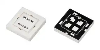
HP2356.A
Patch Antenna, 1.603GHz, GPS / GNSS / Glonass / Galileo / BeiDou / LNA / QZSS / SBAS, -1.6dBi
⚠️ Reference pricing provided. In case of supply shortages, we will connect you with our trusted procurement partners to ensure your project's continuity.
- Manufacturer: TAOGLAS
- Product type:
- Gain: -1.6dBi
- VSWR: 1.5
- Frequency Max: 1.603GHz
- Input Impedance: 50ohm
| Delivery and price | |
|---|---|
| Units per pack | 250 |
| Price | 7.39 € |
| Current stock | 100+ |
| Lead time | 30 days |
Datasheet

## AS a” KK TAOGLAS. + 5 Qd i Y) (O + a0) a ; ¢ aN | **==> picture [107 x 38] intentionally omitted <==** **----- Start of picture text -----**<br> y |<br>**----- End of picture text -----**<br> Inception Series **Part No: HP2356.A** **Description** Inception Series Low Profile High Precision GNSS L1/L2 Passive Patch Antenna **Features:** Compact, 6mm thick Innovative ‘patch within a patch’ design Bands Covered: • BeiDou (B1I) •GPS/QZSS (L1/L2) •Galileo E5b • GLONASS (G1) Dual Feed SDM Configuration Dimensions: 35mm x 35mm x 6mm RoHS & Reach Compliant SPE-24-8-343-B www.taoglas.com **==> picture [358 x 218] intentionally omitted <==** **----- Start of picture text -----**<br> 1. Introduction 3<br>2. Specification 3<br>3. Mechanical Drawing 6<br>4. Antenna Integration Guide 7<br>5. Packaging 15<br>6. Antenna Characteristics 16<br>7. Radiation Patterns 20<br>Changelog 26<br>**----- End of picture text -----**<br> Taoglas makes no warranties based on the accuracy or completeness of the contents of this document and reserves the right to make changes to specifications and product descriptions at any time without notice. Taoglas reserves all rights to this document and the information contained herein. Reproduction, use or disclosure to third parties without express permission is strictly prohibited. 2 www.taoglas.com SPE-24-8-343-B The Taoglas Inception Series HP2356.A, is a multi-band GNSS passive patch antenna designed for optimum positional accuracy and positioning. It utilizes an innovative ceramic patch within a patch antenna design with optimized gain for GPS L1/L2, Galileo, GLONASS and BeiDou bands and measures just 35*35*6mm. This ground-breaking design allows customers to integrate a multi-band L1/L2 GNSS patch into devices where this would not have been possible before due to height constraints. At only 6mm in height, the HP2356,A can be used in a variety of applications where typical stacked patch designs are too tall for the device. Typical Applications Include: - Wearables - Compact Asset Trackers - Precision Agriculture - Navigation - Industrial Tracking - Autonomous Vehicles & Robotics The HP2356.A has been tuned and tested on a 70 x 70mm ground plane and exhibits excellent radiation patterns. It is optimized to cover the bands required for the next generation of L1/L2 Multiband GNSS receivers that are currently available on the market. If you require an easy to integrate active electronic circuit for the HP2356.A, the Taoglas TFM.100A can be designed onto the device PCB alongside the antenna. The module features a SAW/LNA/SAW/LNA topology in both the low and high band signal paths to prevent unwanted out-of-band interference from overdriving the GNSS LNAs or receiver. The SAW filters have been carefully selected and placed to provide excellent out-of band rejection while also maintaining low noise figure. Care should be taken when integrating this antenna into a customer device. Patch antennas can be specifically tuned to customer-specific device environments, subject to NRE and MOQ. Contact your regional Taoglas customer support team to request these services or additional support to integrate and test this antenna’s performance in your device. 3 www.taoglas.com SPE-24-8-343-B |**GNSS Frequency Bands**|**GNSS Frequency Bands**|**GNSS Frequency Bands**|**GNSS Frequency Bands**|**GNSS Frequency Bands**|**GNSS Frequency Bands**| |---|---|---|---|---|---| |**GPS**|**L1**<br>**1575.42 MHz**|**L2**<br>**1227.6 MHz**|**L5**<br>**1176.45 MHz**||| ||◼||||| |**GLONASS**|**G1**<br>**1602 MHz**|**G2**<br>**1248 MHz**|**G3**<br>**1207 MHz**||| ||◼||||| |**Galileo**|**E1**<br>**1575.24 MHz**|**E5a**<br>**1176.45 MHz**|**E5b**<br>**1207 MHz**|**E6**<br>**1278.75 MHz**|| ||◼||◼||| |**BeiDou**|**B1C**<br>**1575.42 MHz**|**B1I**<br>**1561 MHz**|**B2a**<br>**1176.45 MHz**|**B2b**<br>**1207.14 MHz**|**B3**<br>**1268.52 MHz**| ||◼|◼|||| |**L-Band**|**L-Band**<br>**1542 MHz**||||| ||||||| |**QZSS (Regional)**|**L1**<br>**1575.42 MHz**|**L2C**<br>**1227.6 MHz**|**L5**<br>**1176.45 MHz**|**L6**<br>**1278.75e6**|| ||◼||||| |**IRNSS (Regional)**|**L5**<br>**1176.45 MHz**||||| ||||||| |**SBAS**|**L1/E1/B1**<br>**1575.42 MHz**|**L5/B2a/E5a**<br>**1176.45 MHz**|**G1**<br>**1602 MHz**|**G2**<br>**1248 MHz**|**G3**<br>**1207 MHz**| ||◼||◼||| GNSS Bands and Constellations 4 www.taoglas.com SPE-24-8-343-B ||||||| |---|---|---|---|---|---| ||**GNSS Electrical**||||| ||||||| ||||||| |**Frequency (MHz)**|**1207**|**1227.6**|**1561**|**1575.42**|**1603**| ||||||| ||||||| |**VSWR (max.)**|1.5:1|1.5:1|1.5:1|1.5:1|1.5:1| ||||||| ||||||| |**Efficiency (%)**|15|36.5|24.9|55.2|26.0| ||||||| ||||||| |**Average Gain (dB)**|-8.32|-4.38|-6.03|-2.58|-5.84| ||||||| ||||||| |**Peak Gain (dBi)**|-2.69|1.25|-1.80|1.60|-1.6| ||||||| ||||||| |**Axial Ratio (dB)**|2.07|3.34|2.59|2.86|1.77| ||||||| ||||||| |**Polarization**|RHCP||||| ||||||| ||||||| |**Impedance**|50 Ω||||| ||||||| ## **Mechanical** |**Mechanical**|**Mechanical**| |---|---| ||| |**Dimensions**|35 x 35 x 6mm| ||| ||| |**Weight**|30g| ||| ||| |**Material**|Ceramic| ||| ||**Environmental**| |---|---| ||| |**Operation Temperature**|-40 - +85°C| ||| ||| |**Storage Temperature**|-40 - +85°C| ||| ||| |**Humidity**|Non-condensing 65°C 95% RH| ||| ||| |**Moisture Sensitivity Level (MSL)**|3| ||| 5 www.taoglas.com SPE-24-8-343-B 6 www.taoglas.com SPE-24-8-343-B The following is an example on how to integrate the HP2356.A into a design. This antenna has twelve pins, two pins are used for the L1 band, and the other two pins are used for the L2 band. Hybrid couplers (HC125A) are used to combine the feeds for the L1 & L2 bands, to create a Right Hand Circular Polarized (RHCP) signal at the output of the hybrid couplers. Taoglas recommends using a minimum of 70x70mm ground plane (PCB) to ensure optimal performance before being presented to the GNSS Module. Taoglas recommends our TFM.100A, a high-performance GNSS Module specifically engineered for use with our multi feed patch antennas. Top and bottom view of reference design board. Please find the Integration files in Altium, 2D formats and the 3D model for the HP2356.A here: https://www.taoglas.com/product/inception-series-multi-band-gnss-l1-l2-low-profile-patch-antenna/ 7 www.taoglas.com SPE-24-8-343-B ## Schematic Symbol and Pin Definitions **==> picture [101 x 27] intentionally omitted <==** **----- Start of picture text -----**<br> Hybrid Couplers<br>(HC125A) on the PCB.<br>**----- End of picture text -----**<br> Above are the 3D models of the HP2356.A and HC125A on the reference design board. The circuit symbol for the HP2356.A is shown below. The schematic symbol for the antenna has 12 pins as indicated below. |**Feed**|**Description**| |---|---| |1|L1 (90˚ )| |2|L1 (0˚ )| |3-10|Ground| |11|L2 (90˚ )| |12|L2 (0°˚)| Above is a schematic symbol of HP2356.A and a table of the pin definitions. 8 www.taoglas.com SPE-24-8-343-B ## Schematic Layout The HP2356.A uses two orthogonal feeds that need to be combined in a hybrid coupler to ensure optimal axial ratio and RHCP Gain is achieved. Taoglas recommends our HC125A, a high-performance hybrid coupler specifically engineered for use with our multi feed patches. The HC125A is required for the high GNSS band of operation (1559- 1610MHz) for this antenna. This hybrid coupler should be placed close to the antenna feed pads and terminated correctly using a 49.9 Ohm resistor. |**Designator**|**Type**|**Value**|**Manufacturer**|**Manufacturer Part**<br>**Number**| |---|---|---|---|---| |R1|Resistor|49.9 Ohms|Panasonic|ERJ-2RKF49R9X| 9 www.taoglas.com SPE-24-8-343-B ## Antenna Footprint **==> picture [34 x 60] intentionally omitted <==** **----- Start of picture text -----**<br> Lh<br>**----- End of picture text -----**<br> 10 www.taoglas.com SPE-24-8-343-B ## Top Solder Paste 11 www.taoglas.com SPE-24-8-343-B ## Copper Clearance for HP2356.A The footprint and clearance on the PCB must comply with the antenna’s specification. The PCB layout shown in the diagrams below demonstrates the HP2356.A clearance area for Pin 1 (L1P2(90˚ ) Pad), Pin 2 (L1P1(0˚ ) Pad), Pin 11 (L2P2(90˚ ) Pad) and Pin 12 (L2P1(0˚ ) Pad). The copper keep out area only applies to the top layer. There should be a 3x2.5mm copper clearance area around the antenna pins on the PCB. 3D Image of Copper Clearances for HP2356.A. Copper Clearances Pad Details of the HP2356.A. 12 www.taoglas.com SPE-24-8-343-B ## Antenna Integration The HP5354.A should be placed in the centre of the final design board to take advantage of the ground plane. The RF traces must maintain a 50 Ohm transmission line. From the hybrid coupler a “Pi” Matching Network is recommended for the RF transmission lines, the values and components for the matching circuit will depend on the tuning needed. Also shown is the 49.9 Ohm terminating resistor necessary for the hybrid coupler (HC125A). Ground vias should be placed around the transmission lines and the copper clearance area. Bottom view of the reference design board, showing “Pi” matching network. Bottom view of the reference design board, showing transmission lines and integration notes. 13 www.taoglas.com SPE-24-8-343-B ## Final Integration The bottom side image shown below highlights the antenna connection to the hybrid couplers (HC125A). It shows the 49.9 Ohm terminating resistors necessary for the hybrid coupler (HC125A). Taoglas recommends using a minimum of 70x70mm ground plane (PCB) to ensure optimal performance. Top Side (HP2356.A placement on 70x70mm reference design board) Bottom side (TFM.100A) placement including HC125A) 14 www.taoglas.com SPE-24-8-343-B 100pcs HP2356.A per Reel 2pcs 3g Desiccant 1pcs Humidity test paper **==> picture [74 x 77] intentionally omitted <==** **----- Start of picture text -----**<br> 330mm<br>330mm<br>**----- End of picture text -----**<br> 100pcs HP2356.A per Vacuum bag 100pcs HP2356.A per Inner Carton Dimensions: 350 x 340 x 65mm Weight: 3.3Kg 400pcs HP2356.A per Box Dimensions: 370 x 360 x 275mm Weight: 14Kg **==> picture [202 x 254] intentionally omitted <==** **----- Start of picture text -----**<br> 50m, _ - aso<br>275mm<br>370mm 360mm<br>60mm<br>**----- End of picture text -----**<br> 15 www.taoglas.com SPE-24-8-343-B ## Test Setup VNA Test Set-up 16 www.taoglas.com SPE-24-8-343-B ## Return Loss ## VSWR 17 www.taoglas.com SPE-24-8-343-B ## Efficiency ## Average Gain 18 www.taoglas.com SPE-24-8-343-B ## Peak Gain ## Axial Ratio 19 www.taoglas.com SPE-24-8-343-B ## Test Setup Chamber Test Set-up 20 www.taoglas.com SPE-24-8-343-B ## L2 Patterns at 1200 MHz ## XZ Plane ## YZ Plane ## XY Plane 21 www.taoglas.com SPE-24-8-343-B ## L2 Patterns at 1228 MHz ## XZ Plane ## YZ Plane ## XY Plane 22 www.taoglas.com SPE-24-8-343-B ## L1 Patterns at 1561 MHz ## XZ Plane ## YZ Plane ## XY Plane 23 www.taoglas.com SPE-24-8-343-B ## L1 Patterns at 1575 MHz ## XZ Plane ## YZ Plane ## XY Plane 24 www.taoglas.com SPE-24-8-343-B ## L1 Patterns at 1603 MHz ## XZ Plane ## YZ Plane ## XY Plane 25 www.taoglas.com SPE-24-8-343-B ## Changelog for the datasheet **SPE-24-8-343 - HP2356.A** ## **Revision: B (Current Version)** Date: 2026-03-30 Changes: Full pad numbering on footprint drawing. Changes Made by: Gary West ## **Previous Revisions** **Revision: A (Original First Release)** Date: 2024-12-20 Notes: Initial Release. Author: Gary West 26 www.taoglas.com SPE-24-8-343-B 27 www.taoglas.com SPE-24-8-343-B
Updated at June 9, 2026
About Novapart
Novapart is a B2B electronic component broker specialising in stock shortages and cost reduction. We source hard-to-find parts and identify compliant alternatives across a catalogue of 410,000+ components from 500+ manufacturers.
Learn more →Stock Shortage Specialist
When a component is unavailable, discontinued or has an unacceptable lead time, we tap into our network of vetted European and Asian distributors to source what you need — without compromising on quality or traceability.
Request a quote →Compliant Alternatives
We identify pin-to-pin, electrically equivalent substitutes that meet the same certifications (RoHS, AEC-Q100, REACH) as your original specification — validated against datasheets, not just part numbers. Often at a lower cost.
BOM Analysis service →