
Image not available
Illustrative purposes only

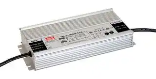
HLG-480H-24
LED Driver, 480 W, 24 VDC, 20 A, Constant Current, Constant Voltage, 90 V
⚠️ Reference pricing provided. In case of supply shortages, we will connect you with our trusted procurement partners to ensure your project's continuity.
- Manufacturer: MEAN WELL
- Product type: AC / DC LED Power Supplies
- Output Power Max:480W; Output Voltage Max:24V; Output Current:20A; LED Driver Mode:Constant Current, Constant Voltage; Input Voltage Min:90V; Input Voltage Max:305V; Product Range:HLG-480
- SVHC: No SVHC (25-Jun-2025)
- Product Range: HLG-480H
- Output Current: 20A
- LED Driver Mode: Constant Current, Constant Voltage
- Output Power Max: 480W
- Input Voltage Max: 305V
- Input Voltage Min: 90V
- Output Voltage Max: 24VDC
- Power Supply Applications: -
| Delivery and price | |
|---|---|
| Units per pack | 10 |
| Price | 114.0 € |
| Current stock | 10+ |
| Lead time | 30 days |
Datasheet

> 480W  Constant Voltage + Constant Current LED Driver **HLG - 480H series**

## ■

## **IP65 IP67**

> (except for AB,Dx,D2-type) [© GWType HL &: @ HI CBCe ■

Metal housing with class I design Built-in active PFC function

Ⅰ,

## ■

current output. HLG-480H operates from 90~305VAC and offers models with different rated voltage ranging between 24V and 54V. Thanks to the high efficiency up to 95.5%, with the fanless design, the entire series is able to operate for -40℃ ~ +90℃ case temperature under free air convection. The design of metal housing and IP67/IP65 ingress protection level allows this series to fit both indoor and outdoor applications.HLG-480H is equipped with various function options, such as dimming methodologies, so as to provide the optimal design flexibility for LED lighting system.

## ■

IPLevel | IP67 I o I B **IP6** 57 | 3oin AB I o IP65 | 3 in Dx

_File Name:HLG-480H-SPEC   2018-08-27_

> 480W  Constant Voltage + Constant Current LED Driver **HLG - 480H series**

## **SPECIFICATION**

|**CONSTANT CURRENT REGION Note.4**<br>**MODEL**<br>**DC VOLTAGE**<br>**OUTPUT**<br>**CURRENT ADJ. RANGE**<br>**LINE REGULATION**<br>**LOAD REGULATION**<br>**SETUP, RISE TIME**<br>**Note.6**<br>**HOLD UP TIME (Typ.)**<br>**VOLTAGE RANGE**<br>**Note.5**<br>**FREQUENCY RANGE**<br>**POWER FACTOR (Typ.)**<br>**AC CURRENT (Typ.)**<br>**INPUT**<br>**INRUSH CURRENT(Typ.)**<br>**LEAKAGE CURRENT**<br>**MAX. NO. of PSUs on 16A**<br>**CIRCUIT BREAKER**<br>**SAFETY STANDARDS**<br>**WORKING TEMP.**<br>**WORKING HUMIDITY**<br>**MAX. CASE TEMP.**<br>**STORAGE TEMP., HUMIDITY**<br>**VIBRATION**<br>**MTBF**<br>**DIMENSION**<br>**OTHERS**<br>**OVER CURRENT**<br>**OVER VOLTAGE**<br>**OVER TEMPERATURE**<br>47 ~ 63Hz<br>PF<br>0.98/115VAC, PF<br>0.97/230VAC, PF<br>0.95/277VAC @ full load<br>≧<br>≧<br>≧<br>5A / 115VAC          2.45A / 230VAC          2A / 277VAC<br><0.75mA / 277VAC<br>2unit(circuit breaker of type B) / 3units(circuit breaker of type C) at 230VAC<br>95 ~ 108%<br>Constant current limiting, recovers automatically after fault condition is removed<br>20 ~ 95% RH non-condensing<br>Tcase=+90℃<br>-40 ~ +80<br>, 10 ~ 95% RH<br>℃<br>non-condensing<br>10 ~ 500Hz, 5G 12min./1cycle, period for  72min. each along X, Y, Z axes<br>345.5K hrs min.<br>Telcordia SR-332(Bellcore) ; 95.3K hrs min.      MIL-HDBK-217F (25<br>)<br>℃<br>262*125*43.8mm (L*W*H)<br>**VOLTAGE TOLERANCE Note.3**<br>**ENVIRONMENT**<br>**SAFETY &**<br>**EMC**<br>**PROTECTION SHORT CIRCUIT**<br>Constant current limiting, recovers automatically after fault condition is removed<br>94%<br>94.5%<br>94.5%<br>95%<br>95%<br>95.5%<br>95%<br>95.5%<br>94.5%<br>95%<br>95%<br>95%<br>±1.0%<br>±1.0%<br>±1.0%<br>±1.0%<br>±1.0%<br>±1.0%<br>10 ~ 20A<br>8 ~ 16A<br>6.6 ~ 13.3A<br>5.7 ~ 11.4A<br>5 ~ 10A<br>4.4 ~ 8.9A<br>±0.5%<br>±0.5%<br>±0.5%<br>±0.5%<br>±0.5%<br>±0.5%<br>±0.5%<br>±0.5%<br>±0.5%<br>±0.5%<br>±0.5%<br>±0.5%<br>24V<br>**HLG-480H-24**<br>**HLG-480H-30**<br>**HLG-480H-36**<br>**HLG-480H-42**<br>**HLG-480H-48**<br>**HLG-480H-54**<br>30V<br>36V<br>42V<br>48V<br>54V<br>12 ~ 24V<br>15 ~ 30V<br>18 ~ 36V<br>21 ~ 42V<br>24 ~ 48V<br>27 ~ 54V<br>**EMC IMMUNITY**<br>**EMC EMISSION**<br>COLD START 35A(t<br>=1800  s measured at 50% I<br>) at 230VAC; Per NEMA 410<br>width<br>peak<br>**TOTAL HARMONIC DISTORTION**<br>THD< 20% (@ load<br>40% / 115VAC,230VAC,277VAC)<br>≧<br>(Please refer to TOTAL HARMONIC DISTORTION (THD) section)<br>"<br>"<br>I/P-O/P:3.75KVAC     I/P-FG:2KVAC     O/P-FG:1.5KVAC<br>UL8750(type”HL”), CSA C22.2 No. 250.13-12; ENEC EN61347-1, EN61347-2-13 independent, EN62384; GB19510.14,GB19510.1;<br>IP65 or IP67<br>;<br>approved<br>,<br>,<br>(except for AB,Dx,D2-type)<br>EAC TP TC 004<br>KC KN61347 1 KN61347 2 13<br>- ,<br>- -<br>AS/NZS 60950.1(by CB)<br>I/P-O/P, I/P-FG, O/P-FG:100M Ohms / 500VDC / 25<br>/ 70% RH<br>℃<br>16ms     115VAC/230VAC<br>500ms, 80ms 115VAC/230VAC<br>90 ~ 305VAC          127 ~ 431VDC<br>(Please refer to "STATIC CHARACTERISTIC" section)<br>Tcase=-40 ~ +90℃(Please refer to "OUTPUT LOAD vs TEMPERATURE" section)<br>Shut down output voltage, re-power on to recovery<br>Shut down output voltage, re-power on to recovery<br>**RATED CURRENT**<br>**RATED POWER**<br>**VOLTAGE ADJ. RANGE**<br>**RIPPLE & NOISE (max.) Note.2**<br>20A<br>16A<br>13.3A<br>11.4A<br>10A<br>8.9A<br>480W<br>480W<br>478.8W<br>478.8W<br>480W<br>480.6W<br>200mVp-p<br>200mVp-p<br>250mVp-p<br>250mVp-p<br>250mVp-p<br>350mVp-p<br>Adjustable for A/AB-Type only (via built-in potentiometer)<br>Adjustable for A/AB-Type only (via built-in potentiometer)<br>20.4 ~ 25.2V<br>25.5 ~ 31.5V<br>30.6 ~ 37.8V<br>35.7 ~ 44.1V<br>40.8 ~ 50.4V<br>45.9 ~ 56.7V<br>27 ~ 33V<br>33 ~ 40V<br>40 ~ 50V<br>46 ~ 55V<br>53 ~ 63V<br>60 ~ 70V<br>(Please refer to "<br>" section)<br>POWER FACTOR (PF) CHARACTERISTIC<br>**ISOLATION RESISTANCE**<br>**WITHSTAND VOLTAGE**<br>**TEMP. COEFFICIENT**<br>±<br>℃<br>℃<br>0.02%/<br>(0 ~ 60<br>)<br>**PACKING**<br>2.8Kg;4pcs/12.2Kg/0.55CUFT<br>**NOTE**<br>℃<br>℃<br>℃<br>℃<br>μ<br>**EFFICIENCY**<br>**(Typ.)**<br>230VAC<br>277VAC<br>Compliance to EN55032 (CISPR32) Class B EN55015, EN61000-3-2  Class C (@ load<br>50%) ; EN61000-3-3;<br>,<br>≧<br>GB17743, GB17625.1 EAC TP TC 020<br>,<br>;KC KN15,KN61547(<br>)<br>except for AB,Dx,D2-type<br>Compliance to<br>,<br>EN61000-4-2,3,4,5,6,8,11, EN61547, light industry level (surge immunity Line-Earth 4KV, Line-Line 2KV)<br>EAC TP TC 020;KC KN15,KN61547(<br>)<br>except for AB,Dx,D2-type<br>a ~~GC~~<br>~~ee~~ GG<br>~~GG~~<br>Re~~GG~~<br>a ~~GC~~<br>~~Ce~~<br>Rs<br>~~Re~~<br>es<br>GQ<br>~~GG~~<br>Re ~~GO~~<br>a~~I~~<br>a<br>ars~~GO~~<br>Po<br>a<br>rs<br>eeCn<br>Ce<br>~~ee~~<br>~~se~~<br>Ge<br>~~Re~~<br>~~ee~~<br>es<br>a~~ee~~<br>~~ee~~<br>a<br>a<br>a<br>~~ee~~<br>es<br>a<br>1. All parameters NOT specially mentioned are measured at230VAC input, rated current and 25 _—_of ambient temperature.<br>2. Ripple & noise are measured at 20MHz of bandwidth by using a 12" twisted pair-wire terminated with a 0.1uf & 47uf parallel capacitor.<br>3. Tolerance<br>: includes set up tolerance, line regulation and load regulation.<br>4. Please refer to "DRIVING METHODS OF LED MODULE".<br>5. De-rating may be needed under low input voltages. Please refer to “STATIC CHARACTERISTIC” sections for details.<br>6. Length of set up time is measured at first cold start. Turning ON/OFF the driver may lead to increase of the set up time.<br>7. The driver is considered as a component that will be operated in combination with final equipment. Since EMC performance will be affected by the<br>complete installation, the final equipment manufacturers must re-qualify EMC Directive on the complete installation again.<br>8. To fulfill requirements of the latest ErP regulation for lighting fixtures, this LED driver can only be used behind a switch without permanently<br>connected to the mains.<br>9. This series meets the typical lifeexpectancy of>62,000 hours of operationwhen Tcase, particularlyto)point (orTMP, per DLC), isabout 75<br>or less.<br>10. Please refer to the warranty statement on MEAN WELL's website at http:/Avwww.meanwell.com<br>11. The ambient temperature derating of 3.5<br>/1000m with fanless models and of<br>5<br>=/1000m with fan models for operating altitude higher than 2000m(6500ft)||**CONSTANT CURRENT REGION Note.4**<br>**MODEL**<br>**DC VOLTAGE**<br>**OUTPUT**<br>**CURRENT ADJ. RANGE**<br>**LINE REGULATION**<br>**LOAD REGULATION**<br>**SETUP, RISE TIME**<br>**Note.6**<br>**HOLD UP TIME (Typ.)**<br>**VOLTAGE RANGE**<br>**Note.5**<br>**FREQUENCY RANGE**<br>**POWER FACTOR (Typ.)**<br>**AC CURRENT (Typ.)**<br>**INPUT**<br>**INRUSH CURRENT(Typ.)**<br>**LEAKAGE CURRENT**<br>**MAX. NO. of PSUs on 16A**<br>**CIRCUIT BREAKER**<br>**SAFETY STANDARDS**<br>**WORKING TEMP.**<br>**WORKING HUMIDITY**<br>**MAX. CASE TEMP.**<br>**STORAGE TEMP., HUMIDITY**<br>**VIBRATION**<br>**MTBF**<br>**DIMENSION**<br>**OTHERS**<br>**OVER CURRENT**<br>**OVER VOLTAGE**<br>**OVER TEMPERATURE**<br>47 ~ 63Hz<br>PF<br>0.98/115VAC, PF<br>0.97/230VAC, PF<br>0.95/277VAC @ full load<br>≧<br>≧<br>≧<br>5A / 115VAC          2.45A / 230VAC          2A / 277VAC<br><0.75mA / 277VAC<br>2unit(circuit breaker of type B) / 3units(circuit breaker of type C) at 230VAC<br>95 ~ 108%<br>Constant current limiting, recovers automatically after fault condition is removed<br>20 ~ 95% RH non-condensing<br>Tcase=+90℃<br>-40 ~ +80<br>, 10 ~ 95% RH<br>℃<br>non-condensing<br>10 ~ 500Hz, 5G 12min./1cycle, period for  72min. each along X, Y, Z axes<br>345.5K hrs min.<br>Telcordia SR-332(Bellcore) ; 95.3K hrs min.      MIL-HDBK-217F (25<br>)<br>℃<br>262*125*43.8mm (L*W*H)<br>**VOLTAGE TOLERANCE Note.3**<br>**ENVIRONMENT**<br>**SAFETY &**<br>**EMC**<br>**PROTECTION SHORT CIRCUIT**<br>Constant current limiting, recovers automatically after fault condition is removed<br>94%<br>94.5%<br>94.5%<br>95%<br>95%<br>95.5%<br>95%<br>95.5%<br>94.5%<br>95%<br>95%<br>95%<br>±1.0%<br>±1.0%<br>±1.0%<br>±1.0%<br>±1.0%<br>±1.0%<br>10 ~ 20A<br>8 ~ 16A<br>6.6 ~ 13.3A<br>5.7 ~ 11.4A<br>5 ~ 10A<br>4.4 ~ 8.9A<br>±0.5%<br>±0.5%<br>±0.5%<br>±0.5%<br>±0.5%<br>±0.5%<br>±0.5%<br>±0.5%<br>±0.5%<br>±0.5%<br>±0.5%<br>±0.5%<br>24V<br>**HLG-480H-24**<br>**HLG-480H-30**<br>**HLG-480H-36**<br>**HLG-480H-42**<br>**HLG-480H-48**<br>**HLG-480H-54**<br>30V<br>36V<br>42V<br>48V<br>54V<br>12 ~ 24V<br>15 ~ 30V<br>18 ~ 36V<br>21 ~ 42V<br>24 ~ 48V<br>27 ~ 54V<br>**EMC IMMUNITY**<br>**EMC EMISSION**<br>COLD START 35A(t<br>=1800  s measured at 50% I<br>) at 230VAC; Per NEMA 410<br>width<br>peak<br>**TOTAL HARMONIC DISTORTION**<br>THD< 20% (@ load<br>40% / 115VAC,230VAC,277VAC)<br>≧<br>(Please refer to TOTAL HARMONIC DISTORTION (THD) section)<br>"<br>"<br>I/P-O/P:3.75KVAC     I/P-FG:2KVAC     O/P-FG:1.5KVAC<br>UL8750(type”HL”), CSA C22.2 No. 250.13-12; ENEC EN61347-1, EN61347-2-13 independent, EN62384; GB19510.14,GB19510.1;<br>IP65 or IP67<br>;<br>approved<br>,<br>,<br>(except for AB,Dx,D2-type)<br>EAC TP TC 004<br>KC KN61347 1 KN61347 2 13<br>- ,<br>- -<br>AS/NZS 60950.1(by CB)<br>I/P-O/P, I/P-FG, O/P-FG:100M Ohms / 500VDC / 25<br>/ 70% RH<br>℃<br>16ms     115VAC/230VAC<br>500ms, 80ms 115VAC/230VAC<br>90 ~ 305VAC          127 ~ 431VDC<br>(Please refer to "STATIC CHARACTERISTIC" section)<br>Tcase=-40 ~ +90℃(Please refer to "OUTPUT LOAD vs TEMPERATURE" section)<br>Shut down output voltage, re-power on to recovery<br>Shut down output voltage, re-power on to recovery<br>**RATED CURRENT**<br>**RATED POWER**<br>**VOLTAGE ADJ. RANGE**<br>**RIPPLE & NOISE (max.) Note.2**<br>20A<br>16A<br>13.3A<br>11.4A<br>10A<br>8.9A<br>480W<br>480W<br>478.8W<br>478.8W<br>480W<br>480.6W<br>200mVp-p<br>200mVp-p<br>250mVp-p<br>250mVp-p<br>250mVp-p<br>350mVp-p<br>Adjustable for A/AB-Type only (via built-in potentiometer)<br>Adjustable for A/AB-Type only (via built-in potentiometer)<br>20.4 ~ 25.2V<br>25.5 ~ 31.5V<br>30.6 ~ 37.8V<br>35.7 ~ 44.1V<br>40.8 ~ 50.4V<br>45.9 ~ 56.7V<br>27 ~ 33V<br>33 ~ 40V<br>40 ~ 50V<br>46 ~ 55V<br>53 ~ 63V<br>60 ~ 70V<br>(Please refer to "<br>" section)<br>POWER FACTOR (PF) CHARACTERISTIC<br>**ISOLATION RESISTANCE**<br>**WITHSTAND VOLTAGE**<br>**TEMP. COEFFICIENT**<br>±<br>℃<br>℃<br>0.02%/<br>(0 ~ 60<br>)<br>**PACKING**<br>2.8Kg;4pcs/12.2Kg/0.55CUFT<br>**NOTE**<br>℃<br>℃<br>℃<br>℃<br>μ<br>**EFFICIENCY**<br>**(Typ.)**<br>230VAC<br>277VAC<br>Compliance to EN55032 (CISPR32) Class B EN55015, EN61000-3-2  Class C (@ load<br>50%) ; EN61000-3-3;<br>,<br>≧<br>GB17743, GB17625.1 EAC TP TC 020<br>,<br>;KC KN15,KN61547(<br>)<br>except for AB,Dx,D2-type<br>Compliance to<br>,<br>EN61000-4-2,3,4,5,6,8,11, EN61547, light industry level (surge immunity Line-Earth 4KV, Line-Line 2KV)<br>EAC TP TC 020;KC KN15,KN61547(<br>)<br>except for AB,Dx,D2-type<br>a ~~GC~~<br>~~ee~~ GG<br>~~GG~~<br>Re~~GG~~<br>a ~~GC~~<br>~~Ce~~<br>Rs<br>~~Re~~<br>es<br>GQ<br>~~GG~~<br>Re ~~GO~~<br>a~~I~~<br>a<br>ars~~GO~~<br>Po<br>a<br>rs<br>eeCn<br>Ce<br>~~ee~~<br>~~se~~<br>Ge<br>~~Re~~<br>~~ee~~<br>es<br>a~~ee~~<br>~~ee~~<br>a<br>a<br>a<br>~~ee~~<br>es<br>a<br>1. All parameters NOT specially mentioned are measured at230VAC input, rated current and 25 _—_of ambient temperature.<br>2. Ripple & noise are measured at 20MHz of bandwidth by using a 12" twisted pair-wire terminated with a 0.1uf & 47uf parallel capacitor.<br>3. Tolerance<br>: includes set up tolerance, line regulation and load regulation.<br>4. Please refer to "DRIVING METHODS OF LED MODULE".<br>5. De-rating may be needed under low input voltages. Please refer to “STATIC CHARACTERISTIC” sections for details.<br>6. Length of set up time is measured at first cold start. Turning ON/OFF the driver may lead to increase of the set up time.<br>7. The driver is considered as a component that will be operated in combination with final equipment. Since EMC performance will be affected by the<br>complete installation, the final equipment manufacturers must re-qualify EMC Directive on the complete installation again.<br>8. To fulfill requirements of the latest ErP regulation for lighting fixtures, this LED driver can only be used behind a switch without permanently<br>connected to the mains.<br>9. This series meets the typical lifeexpectancy of>62,000 hours of operationwhen Tcase, particularlyto)point (orTMP, per DLC), isabout 75<br>or less.<br>10. Please refer to the warranty statement on MEAN WELL's website at http:/Avwww.meanwell.com<br>11. The ambient temperature derating of 3.5<br>/1000m with fanless models and of<br>5<br>=/1000m with fan models for operating altitude higher than 2000m(6500ft)||**CONSTANT CURRENT REGION Note.4**<br>**MODEL**<br>**DC VOLTAGE**<br>**OUTPUT**<br>**CURRENT ADJ. RANGE**<br>**LINE REGULATION**<br>**LOAD REGULATION**<br>**SETUP, RISE TIME**<br>**Note.6**<br>**HOLD UP TIME (Typ.)**<br>**VOLTAGE RANGE**<br>**Note.5**<br>**FREQUENCY RANGE**<br>**POWER FACTOR (Typ.)**<br>**AC CURRENT (Typ.)**<br>**INPUT**<br>**INRUSH CURRENT(Typ.)**<br>**LEAKAGE CURRENT**<br>**MAX. NO. of PSUs on 16A**<br>**CIRCUIT BREAKER**<br>**SAFETY STANDARDS**<br>**WORKING TEMP.**<br>**WORKING HUMIDITY**<br>**MAX. CASE TEMP.**<br>**STORAGE TEMP., HUMIDITY**<br>**VIBRATION**<br>**MTBF**<br>**DIMENSION**<br>**OTHERS**<br>**OVER CURRENT**<br>**OVER VOLTAGE**<br>**OVER TEMPERATURE**<br>47 ~ 63Hz<br>PF<br>0.98/115VAC, PF<br>0.97/230VAC, PF<br>0.95/277VAC @ full load<br>≧<br>≧<br>≧<br>5A / 115VAC          2.45A / 230VAC          2A / 277VAC<br><0.75mA / 277VAC<br>2unit(circuit breaker of type B) / 3units(circuit breaker of type C) at 230VAC<br>95 ~ 108%<br>Constant current limiting, recovers automatically after fault condition is removed<br>20 ~ 95% RH non-condensing<br>Tcase=+90℃<br>-40 ~ +80<br>, 10 ~ 95% RH<br>℃<br>non-condensing<br>10 ~ 500Hz, 5G 12min./1cycle, period for  72min. each along X, Y, Z axes<br>345.5K hrs min.<br>Telcordia SR-332(Bellcore) ; 95.3K hrs min.      MIL-HDBK-217F (25<br>)<br>℃<br>262*125*43.8mm (L*W*H)<br>**VOLTAGE TOLERANCE Note.3**<br>**ENVIRONMENT**<br>**SAFETY &**<br>**EMC**<br>**PROTECTION SHORT CIRCUIT**<br>Constant current limiting, recovers automatically after fault condition is removed<br>94%<br>94.5%<br>94.5%<br>95%<br>95%<br>95.5%<br>95%<br>95.5%<br>94.5%<br>95%<br>95%<br>95%<br>±1.0%<br>±1.0%<br>±1.0%<br>±1.0%<br>±1.0%<br>±1.0%<br>10 ~ 20A<br>8 ~ 16A<br>6.6 ~ 13.3A<br>5.7 ~ 11.4A<br>5 ~ 10A<br>4.4 ~ 8.9A<br>±0.5%<br>±0.5%<br>±0.5%<br>±0.5%<br>±0.5%<br>±0.5%<br>±0.5%<br>±0.5%<br>±0.5%<br>±0.5%<br>±0.5%<br>±0.5%<br>24V<br>**HLG-480H-24**<br>**HLG-480H-30**<br>**HLG-480H-36**<br>**HLG-480H-42**<br>**HLG-480H-48**<br>**HLG-480H-54**<br>30V<br>36V<br>42V<br>48V<br>54V<br>12 ~ 24V<br>15 ~ 30V<br>18 ~ 36V<br>21 ~ 42V<br>24 ~ 48V<br>27 ~ 54V<br>**EMC IMMUNITY**<br>**EMC EMISSION**<br>COLD START 35A(t<br>=1800  s measured at 50% I<br>) at 230VAC; Per NEMA 410<br>width<br>peak<br>**TOTAL HARMONIC DISTORTION**<br>THD< 20% (@ load<br>40% / 115VAC,230VAC,277VAC)<br>≧<br>(Please refer to TOTAL HARMONIC DISTORTION (THD) section)<br>"<br>"<br>I/P-O/P:3.75KVAC     I/P-FG:2KVAC     O/P-FG:1.5KVAC<br>UL8750(type”HL”), CSA C22.2 No. 250.13-12; ENEC EN61347-1, EN61347-2-13 independent, EN62384; GB19510.14,GB19510.1;<br>IP65 or IP67<br>;<br>approved<br>,<br>,<br>(except for AB,Dx,D2-type)<br>EAC TP TC 004<br>KC KN61347 1 KN61347 2 13<br>- ,<br>- -<br>AS/NZS 60950.1(by CB)<br>I/P-O/P, I/P-FG, O/P-FG:100M Ohms / 500VDC / 25<br>/ 70% RH<br>℃<br>16ms     115VAC/230VAC<br>500ms, 80ms 115VAC/230VAC<br>90 ~ 305VAC          127 ~ 431VDC<br>(Please refer to "STATIC CHARACTERISTIC" section)<br>Tcase=-40 ~ +90℃(Please refer to "OUTPUT LOAD vs TEMPERATURE" section)<br>Shut down output voltage, re-power on to recovery<br>Shut down output voltage, re-power on to recovery<br>**RATED CURRENT**<br>**RATED POWER**<br>**VOLTAGE ADJ. RANGE**<br>**RIPPLE & NOISE (max.) Note.2**<br>20A<br>16A<br>13.3A<br>11.4A<br>10A<br>8.9A<br>480W<br>480W<br>478.8W<br>478.8W<br>480W<br>480.6W<br>200mVp-p<br>200mVp-p<br>250mVp-p<br>250mVp-p<br>250mVp-p<br>350mVp-p<br>Adjustable for A/AB-Type only (via built-in potentiometer)<br>Adjustable for A/AB-Type only (via built-in potentiometer)<br>20.4 ~ 25.2V<br>25.5 ~ 31.5V<br>30.6 ~ 37.8V<br>35.7 ~ 44.1V<br>40.8 ~ 50.4V<br>45.9 ~ 56.7V<br>27 ~ 33V<br>33 ~ 40V<br>40 ~ 50V<br>46 ~ 55V<br>53 ~ 63V<br>60 ~ 70V<br>(Please refer to "<br>" section)<br>POWER FACTOR (PF) CHARACTERISTIC<br>**ISOLATION RESISTANCE**<br>**WITHSTAND VOLTAGE**<br>**TEMP. COEFFICIENT**<br>±<br>℃<br>℃<br>0.02%/<br>(0 ~ 60<br>)<br>**PACKING**<br>2.8Kg;4pcs/12.2Kg/0.55CUFT<br>**NOTE**<br>℃<br>℃<br>℃<br>℃<br>μ<br>**EFFICIENCY**<br>**(Typ.)**<br>230VAC<br>277VAC<br>Compliance to EN55032 (CISPR32) Class B EN55015, EN61000-3-2  Class C (@ load<br>50%) ; EN61000-3-3;<br>,<br>≧<br>GB17743, GB17625.1 EAC TP TC 020<br>,<br>;KC KN15,KN61547(<br>)<br>except for AB,Dx,D2-type<br>Compliance to<br>,<br>EN61000-4-2,3,4,5,6,8,11, EN61547, light industry level (surge immunity Line-Earth 4KV, Line-Line 2KV)<br>EAC TP TC 020;KC KN15,KN61547(<br>)<br>except for AB,Dx,D2-type<br>a ~~GC~~<br>~~ee~~ GG<br>~~GG~~<br>Re~~GG~~<br>a ~~GC~~<br>~~Ce~~<br>Rs<br>~~Re~~<br>es<br>GQ<br>~~GG~~<br>Re ~~GO~~<br>a~~I~~<br>a<br>ars~~GO~~<br>Po<br>a<br>rs<br>eeCn<br>Ce<br>~~ee~~<br>~~se~~<br>Ge<br>~~Re~~<br>~~ee~~<br>es<br>a~~ee~~<br>~~ee~~<br>a<br>a<br>a<br>~~ee~~<br>es<br>a<br>1. All parameters NOT specially mentioned are measured at230VAC input, rated current and 25 _—_of ambient temperature.<br>2. Ripple & noise are measured at 20MHz of bandwidth by using a 12" twisted pair-wire terminated with a 0.1uf & 47uf parallel capacitor.<br>3. Tolerance<br>: includes set up tolerance, line regulation and load regulation.<br>4. Please refer to "DRIVING METHODS OF LED MODULE".<br>5. De-rating may be needed under low input voltages. Please refer to “STATIC CHARACTERISTIC” sections for details.<br>6. Length of set up time is measured at first cold start. Turning ON/OFF the driver may lead to increase of the set up time.<br>7. The driver is considered as a component that will be operated in combination with final equipment. Since EMC performance will be affected by the<br>complete installation, the final equipment manufacturers must re-qualify EMC Directive on the complete installation again.<br>8. To fulfill requirements of the latest ErP regulation for lighting fixtures, this LED driver can only be used behind a switch without permanently<br>connected to the mains.<br>9. This series meets the typical lifeexpectancy of>62,000 hours of operationwhen Tcase, particularlyto)point (orTMP, per DLC), isabout 75<br>or less.<br>10. Please refer to the warranty statement on MEAN WELL's website at http:/Avwww.meanwell.com<br>11. The ambient temperature derating of 3.5<br>/1000m with fanless models and of<br>5<br>=/1000m with fan models for operating altitude higher than 2000m(6500ft)||**HLG-480H-24**|**HLG-480H-30**|**HLG-480H-36**|**HLG-480H-42**|**HLG-480H-48**|**HLG-480H-54**|
|---|---|---|---|---|---|---|---|---|
||**DC VOLTAGE**<br>a<br>~~ee~~||24V<br>~~GC~~<br>~~ee~~|30V<br>~~GC~~<br>GG|36V<br>~~GC~~<br>GG|42V<br>~~GC~~<br>GG|48V<br>~~GC~~|54V<br>~~GC~~|
||**CONSTANT CURRENT REGION Note.4**<br>a <br>~~ee~~||12 ~ 24V<br> ~~GC~~<br>~~ee~~|15 ~ 30V<br>~~GC~~<br>GG|18 ~ 36V<br>~~GC~~<br>GG|21 ~ 42V<br>~~GC~~<br>GG|24 ~ 48V<br>~~GC~~|27 ~ 54V<br>~~GC~~|
||**RATED CURRENT**<br>~~ee~~<br>~~GG~~<br>Re||20A<br>~~ee~~ <br>~~GG~~<br>~~GG~~|16A<br> GG<br>~~GG~~<br>~~GG~~|13.3A<br>GG<br>~~GG~~<br>~~GG~~|11.4A<br>GG<br>~~GG~~<br>~~GG~~|10A<br>~~GG~~<br>~~GG~~|8.9A<br>~~GG~~<br>~~GG~~|
||**RATED POWER**<br>~~GG~~<br>Re||480W<br>~~GG~~<br>~~GG~~|480W<br>~~GG~~<br>~~GG~~|478.8W<br>~~GG~~<br>~~GG~~|478.8W<br>~~GG~~<br>~~GG~~|480W<br>~~GG~~<br>~~GG~~|480.6W<br>~~GG~~<br>~~GG~~|
||**RIPPLE & NOISE (max.) Note.2**<br>Re<br>a||200mVp-p<br>~~GG~~<br>~~GC~~|200mVp-p<br>~~GG~~<br>~~GC~~|250mVp-p<br>~~GG~~<br>~~GC~~|250mVp-p<br>~~GG~~<br>~~GC~~|250mVp-p<br>~~GG~~<br>~~GC~~|350mVp-p<br>~~GG~~<br>~~GC~~|
||**VOLTAGE ADJ. RANGE**<br>a||Adjustable for A/AB-Type only (via built-in potentiometer)<br>20.4 ~ 25.2V<br>25.5 ~ 31.5V<br>30.6 ~ 37.8V<br>35.7 ~ 44.1V<br>40.8 ~ 50.4V<br>45.9 ~ 56.7V<br> ~~GC~~<br>~~Ce~~<br>Rs||||||
||**CURRENT ADJ. RANGE**||10 ~ 20A<br>8 ~ 16A<br>6.6 ~ 13.3A<br>5.7 ~ 11.4A<br>5 ~ 10A<br>4.4 ~ 8.9A<br>Adjustable for A/AB-Type only (via built-in potentiometer)<br>Rs<br>~~Re~~<br>es||||||
||**VOLTAGE TOLERANCE Note.3**<br>GQ||±1.0%<br>es<br>GQ|±1.0%<br>GQ|±1.0%<br>GQ|±1.0%<br>GQ|±1.0%<br>GQ|±1.0%<br>GQ|
||**LINE REGULATION**<br>GQ<br>~~GG~~<br>Re||±0.5%<br>GQ<br>~~GG~~<br>~~GO~~|±0.5%<br>GQ<br>~~GG~~<br>~~GO~~|±0.5%<br>GQ<br>~~GG~~<br>~~GO~~|±0.5%<br>GQ<br>~~GG~~<br>~~GO~~|±0.5%<br>GQ<br>~~GG~~<br>~~GO~~|±0.5%<br>GQ<br>~~GG~~<br>~~GO~~|
||**LOAD REGULATION**<br>~~GG~~<br>Re<br>a||±0.5%<br>~~GG~~<br>~~GO~~|±0.5%<br>~~GG~~<br>~~GO~~|±0.5%<br>~~GG~~<br>~~GO~~|±0.5%<br>~~GG~~<br>~~GO~~|±0.5%<br>~~GG~~<br>~~GO~~|±0.5%<br>~~GG~~<br>~~GO~~|
||**SETUP, RISE TIME**<br>**Note.6**<br>Re <br>a~~I~~||500ms, 80ms 115VAC/230VAC<br> ~~GO~~||||||
||**HOLD UP TIME (Typ.)**<br>a~~I~~||16ms     115VAC/230VAC||||||
||**VOLTAGE RANGE**<br>**Note.5**<br>~~I~~||90 ~ 305VAC          127 ~ 431VDC<br>(Please refer to "STATIC CHARACTERISTIC" section)||||||
||**FREQUENCY RANGE**<br>a||47 ~ 63Hz||||||
||**POWER FACTOR (Typ.)**||PF<br>0.98/115VAC, PF<br>0.97/230VAC, PF<br>0.95/277VAC @ full load<br>≧<br>≧<br>≧<br>(Please refer to "<br>" section)<br>POWER FACTOR (PF) CHARACTERISTIC||||||
||**TOTAL HARMONIC DISTORTION**<br><br>Po||THD< 20% (@ load<br>40% / 115VAC,230VAC,277VAC)<br>≧<br>(Please refer to TOTAL HARMONIC DISTORTION (THD) section)<br>"<br>"<br>rs~~GO~~||||||
||**EFFICIENCY**<br>**(Typ.)**<br>Po|230VAC<br>277VAC<br>a<br>Po|94%<br>94.5%<br>ars|94.5%<br>95%<br>~~GO~~|95%<br>95.5%<br>~~GO~~|95%<br>95.5%<br>~~GO~~|94.5%<br>95%<br>~~GO~~|95%<br>95%<br>~~GO~~|
||**AC CURRENT (Typ.)**<br><br>Po<br>a<br>rs||5A / 115VAC          2.45A / 230VAC          2A / 277VAC<br>rs~~GO~~||||||
||**INRUSH CURRENT(Typ.)**<br>a<br>rs<br>ee||COLD START 35A(t<br>=1800  s measured at 50% I<br>) at 230VAC; Per NEMA 410<br>width<br>peak<br>μ<br>||||||
||**LEAKAGE CURRENT**<br>rs<br>ee||<0.75mA / 277VAC<br>||||||
||**MAX. NO. of PSUs on 16A**<br>**CIRCUIT BREAKER**<br>ee||2unit(circuit breaker of type B) / 3units(circuit breaker of type C) at 230VAC<br>||||||
||**OVER CURRENT**<br>||95 ~ 108%<br>Constant current limiting, recovers automatically after fault condition is removed<br>Cn<br>Ce||||||
||**SHORT CIRCUIT**<br>~~ee~~||Constant current limiting, recovers automatically after fault condition is removed<br>Ce<br>~~ee~~<br>Ge||||||
||**OVER VOLTAGE**<br> <br>~~ee~~||Shut down output voltage, re-power on to recovery<br>27 ~ 33V<br>33 ~ 40V<br>40 ~ 50V<br>46 ~ 55V<br>53 ~ 63V<br>60 ~ 70V<br>~~ee~~<br>~~se~~<br>Ge<br>~~Re~~||||||
||**OVER TEMPERATURE**<br>~~ee~~<br>es||Shut down output voltage, re-power on to recovery<br>~~ee~~||||||
||**WORKING TEMP.**<br>~~ee~~<br>es||Tcase=-40 ~ +90℃(Please refer to "OUTPUT LOAD vs TEMPERATURE" section)<br>~~ee~~||||||
||**MAX. CASE TEMP.**<br>es<br>a||Tcase=+90℃<br>||||||
||**WORKING HUMIDITY**<br>a~~ee~~<br>~~ee~~||20 ~ 95% RH non-condensing<br>~~ee~~<br>~~ee~~||||||
||**STORAGE TEMP., HUMIDITY**<br>~~ee~~<br>a||-40 ~ +80<br>, 10 ~ 95% RH<br>℃<br>non-condensing<br>~~ee~~||||||
||**TEMP. COEFFICIENT**<br>a<br>a||±<br>℃<br>℃<br>0.02%/<br>(0 ~ 60<br>)||||||
||**VIBRATION**<br>a<br>a||10 ~ 500Hz, 5G 12min./1cycle, period for  72min. each along X, Y, Z axes||||||
||**SAFETY STANDARDS**<br>a||UL8750(type”HL”), CSA C22.2 No. 250.13-12; ENEC EN61347-1, EN61347-2-13 independent, EN62384; GB19510.14,GB19510.1;<br>IP65 or IP67<br>;<br>approved<br>,<br>,<br>(except for AB,Dx,D2-type)<br>EAC TP TC 004<br>KC KN61347 1 KN61347 2 13<br>- ,<br>- -<br>AS/NZS 60950.1(by CB)||||||
||**WITHSTAND VOLTAGE**<br>a||I/P-O/P:3.75KVAC     I/P-FG:2KVAC     O/P-FG:1.5KVAC||||||
||**ISOLATION RESISTANCE**<br>a<br>~~ee~~||I/P-O/P, I/P-FG, O/P-FG:100M Ohms / 500VDC / 25<br>/ 70% RH<br>℃<br>~~ee~~||||||
||**EMC EMISSION**||Compliance to EN55032 (CISPR32) Class B EN55015, EN61000-3-2  Class C (@ load<br>50%) ; EN61000-3-3;<br>,<br>≧<br>GB17743, GB17625.1 EAC TP TC 020<br>,<br>;KC KN15,KN61547(<br>)<br>except for AB,Dx,D2-type||||||
||**EMC IMMUNITY**<br>es||Compliance to<br>,<br>EN61000-4-2,3,4,5,6,8,11, EN61547, light industry level (surge immunity Line-Earth 4KV, Line-Line 2KV)<br>EAC TP TC 020;KC KN15,KN61547(<br>)<br>except for AB,Dx,D2-type||||||
||**MTBF**<br>es||345.5K hrs min.<br>Telcordia SR-332(Bellcore) ; 95.3K hrs min.      MIL-HDBK-217F (25<br>)<br>℃||||||
||**DIMENSION**<br>es<br>a||262*125*43.8mm (L*W*H)||||||
||**PACKING**<br>a||2.8Kg;4pcs/12.2Kg/0.55CUFT||||||
||℃<br>℃<br>℃<br>℃<br>a<br>1. All parameters NOT specially mentioned are measured at230VAC input, rated current and 25 _—_of ambient temperature.<br>2. Ripple & noise are measured at 20MHz of bandwidth by using a 12" twisted pair-wire terminated with a 0.1uf & 47uf parallel capacitor.<br>3. Tolerance<br>: includes set up tolerance, line regulation and load regulation.<br>4. Please refer to "DRIVING METHODS OF LED MODULE".<br>5. De-rating may be needed under low input voltages. Please refer to “STATIC CHARACTERISTIC” sections for details.<br>6. Length of set up time is measured at first cold start. Turning ON/OFF the driver may lead to increase of the set up time.<br>7. The driver is considered as a component that will be operated in combination with final equipment. Since EMC performance will be affected by the<br>complete installation, the final equipment manufacturers must re-qualify EMC Directive on the complete installation again.<br>8. To fulfill requirements of the latest ErP regulation for lighting fixtures, this LED driver can only be used behind a switch without permanently<br>connected to the mains.<br>9. This series meets the typical lifeexpectancy of>62,000 hours of operationwhen Tcase, particularlyto)point (orTMP, per DLC), isabout 75<br>or less.<br>10. Please refer to the warranty statement on MEAN WELL's website at http:/Avwww.meanwell.com<br>11. The ambient temperature derating of 3.5<br>/1000m with fanless models and of<br>5<br>=/1000m with fan models for operating altitude higher than 2000m(6500ft)|||||||||


℃ MEAN WELL's website at http:/Avwww.meanwell.com ℃ /1000m with fanless models and of 5 ℃ = /1000m with fan models for operating altitude higher than

_File Name:HLG-480H-SPEC   2018-08-27_

## 480W  Constant Voltage + Constant Current LED Driver **HLG - 480H series**

## **BLOCK DIAGRAM**

**==> picture [485 x 137] intentionally omitted <==**

**----- Start of picture text -----**<br>
PFC fosc : 45KHz<br>PWM fosc : 55KHz<br>EMI FILTER PFC POWER RECTIFIERS Vo+<br>I/P & CIRCUIT SWITCHING & Vo-<br>RECTIFIERS FILTER<br>O.L.P. DIM+<br>DIM-<br>(B Type)<br>DETECTION<br>FG O.L.P.<br>PWM CIRCUIT<br>PFC CONTROL<br>CONTROL<br>O.T.P. O.V.P.<br>**----- End of picture text -----**<br>


## **DRIVING METHODS OF LED MODULE**

- ※ This series is able to work in either Constant Current mode (a direct drive way) or Constant Voltage mode (usually through additional DC/DC driver) to drive the LEDs.

**==> picture [442 x 148] intentionally omitted <==**

**----- Start of picture text -----**<br>
In the constant current region, the highest voltage at the output of the driver<br>100<br>depends on the configuration of the end systems.<br>Should there be any compatibility issues, please contact MEAN WELL.<br>(A) Constant (B)<br>Voltage area Constant<br>Current area<br>50<br>50 100 Io (%)<br>Typical output current normalized by rated current (%)<br>Vo(%)<br>**----- End of picture text -----**<br>


_File Name:HLG-480H-SPEC   2018-08-27_

## 480W  Constant Voltage + Constant Current LED Driver **HLG - 480H series**

## **DIMMING OPERATION**

**==> picture [505 x 304] intentionally omitted <==**

**----- Start of picture text -----**<br>
For 24V,30V,36V,42V<br>Vo+(Red)<br>FG   (Green/Yellow) Vo-(Black)<br>Vo+(Red)<br>AC/L(Brown)<br>AC/N(Blue) Vo-(Black)<br>DIM+(Blue)<br>DIM-(White)<br>* DIM+ for B/AB-Type<br>PROG+ for D2-Type<br>* *DIM- for B/AB-Type<br>PROG- for D2-Type<br>For 48V,54V<br>FG   (Green/Yellow)<br>Vo+(Red)<br>AC/L(Brown)<br>AC/N(Blue) Vo-(Black)<br>DIM+(Blue)<br>DIM-(White)<br>* DIM+ for B/AB-Type<br>PROG+ for D2-Type<br>* *DIM- for B/AB-Type<br>PROG- for D2-Type<br>**----- End of picture text -----**<br>


## ※ **3 in 1 dimming function (for B/AB-Type)**

- �Output constant current level can be adjusted by applying one of the three methodologies between DIM+ and DIM-: 0 ~ 10VDC, or 10V PWM signal or resistance.

- �Direct connecting to LEDs is suggested. It is not suitable to be used with additional drivers. �Dimming source current from power supply: 100μA (typ.) ◎ Applying additive 0 ~ 10VDC

**==> picture [157 x 146] intentionally omitted <==**

**----- Start of picture text -----**<br>
100%<br>90%<br>80%<br>70%<br>60%<br>50%<br>40%<br>30%<br>20%<br>10%<br>0%<br>0V 1V 2V 3V 4V 5V 6V 7V 8V 9V 10V<br>Dimming input: Additive voltage<br>Output current (%)<br>**----- End of picture text -----**<br>


**==> picture [215 x 96] intentionally omitted <==**

**----- Start of picture text -----**<br>
+<br>Vo+ +<br>-<br>Vo- -<br>DIM+<br>+<br>Additive Voltage<br>-<br>DIM-<br>“DO NOT connect "DIM- to Vo-"<br>**----- End of picture text -----**<br>


_File Name:HLG-480H-SPEC   2018-08-27_

## 480W  Constant Voltage + Constant Current LED Driver **HLG - 480H series**

**==> picture [227 x 129] intentionally omitted <==**

**----- Start of picture text -----**<br>
◎ Applying additive 10V PWM signal (frequency range 100Hz ~ 3KHz):<br>+<br>Vo+ +<br>-<br>Vo- -<br>DIM+<br>Additive PWM signal<br>DIM-<br>“DO NOT connect "DIM- to Vo+"<br>**----- End of picture text -----**<br>


**==> picture [224 x 125] intentionally omitted <==**

**----- Start of picture text -----**<br>
◎ Applying additive resistance:<br>+<br>Vo+ +<br>-<br>Vo- -<br>DIM+<br>Additive Resistance<br>DIM-<br>“DO NOT connect "DIM- to Vo-"<br>**----- End of picture text -----**<br>


**==> picture [172 x 383] intentionally omitted <==**

**----- Start of picture text -----**<br>
100%<br>90%<br>80%<br>70%<br>60%<br>50%<br>40%<br>30%<br>20%<br>10%<br>0%<br>0% 10% 20% 30% 40% 50% 60% 70% 80% 90% 100%<br>Duty cycle of additive 10V PWM signal dimming input<br>100%<br>90%<br>80%<br>70%<br>60%<br>50%<br>40%<br>30%<br>20%<br>10%<br>0%<br>Short 10K/N 20K/N 30K/N 40K/N 50K/N 60K/N 70K/N 80K/N 90K/N 100K/N<br>(N=driver quantity for synchronized dimming operation)<br>Dimming input: Additive resistance<br>Output current (%)<br>Output current (%)<br>**----- End of picture text -----**<br>


Note : 1. Min. dimming level is about 6% and the output current is not defined when 0%< Iout<6%. 2. The output current could drop down to 0% when dimming input is about 0kΩ or 0Vdc, or 10V PWM signal with 0% duty cycle.

_File Name:HLG-480H-SPEC   2018-08-27_

## 480W  Constant Voltage + Constant Current LED Driver **HLG - 480H series**

※ **Smart timer dimming function (for Dxx-Type  by User definition)** MEAN WELL Smart timer dimming primarily provides the adaptive proportion dimming profile for the output constant current level to perform up to 14 consecutive hours. 3 dimming profiles hereunder are defined accounting for the most frequently seen applications. If other options may be needed, please contact MEAN WELL for details.

**==> picture [209 x 122] intentionally omitted <==**

**----- Start of picture text -----**<br>
Ex : ◎ D01-Type: the profile recommended for residential lighting<br>100iere |<br>||<br>ue |<br>60 ||<br>40<br>30<br>Dimming Level(%)<br>**----- End of picture text -----**<br>


||T1|T2|T3|T4|
|---|---|---|---|---|
|TIME**|06:00|07:00|11:00|---|
|LEVEL**|100%|70%|50%|70%|


Operating Time(HH:MM)

- **: TIME matches Operating Time in the diagram whereas LEVEL matches Dimming Level.

Example: If a residential lighting application adopts D01-Type, when turning on the power supply at 6:00pm, for instance:

- [1] The power supply will switch to the constant current level at 100% starting from 6:00pm.

- [2] The power supply will switch to the constant current level at 70% in turn, starting from 0:00am, which is 06:00 after the power supply turns on.

- [3] The power supply will switch to the constant current level at 50% in turn, starting from 1:00am, which is 07:00 after the power supply turns on.

- [4] The power supply will switch to the constant current level at 70% in turn, starting from 5:00am, which is 11:00 after the power supply turns on. The constant current level remains till 8:00am, which is 14:00 after the power supply turns on.

Ex: ◎ D02-Type: the profile recommended for street lighting

Set up for D02-Type in Smart timer dimming software program:

**==> picture [9 x 59] intentionally omitted <==**

**----- Start of picture text -----**<br>
Dimming Level(%)<br>**----- End of picture text -----**<br>


||T1|T2|T3|T4|T5|
|---|---|---|---|---|---|
|TIME**|01:00|03:00|8:00|11:00|---|
|LEVEL**|50%|80%|100%|60%|80%|


Operating Time(HH:MM)

- **: TIME matches Operating Time in the diagram whereas LEVEL matches Dimming Level.

Example: If a street lighting application adopts D02-Type, when turning on the power supply at 5:00pm, for instance:

- [1] The power supply will switch to the constant current level at 50% starting from 5:00pm.

- [2] The power supply will switch to the constant current level at 80% in turn, starting from 6:00pm, which is 01:00 after the power supply turns on.

- [3] The power supply will switch to the constant current level at 100% in turn, starting from 8:00pm, which is 03:00 after the power supply turns on.

- [4] The power supply will switch to the constant current level at 60% in turn, starting from 1:00am, which is 08:00 after the power supply turns on.

- [5] The power supply will switch to the constant current level at 80% in turn, starting from 4:00am, which is 11:00 after the power supply turns on. The constant current level remains till 6:30am, which is 14:00 after the power supply turns on.

_File Name:HLG-480H-SPEC   2018-08-27_

> 480W  Constant Voltage + Constant Current LED Driver **HLG - 480H series**

|Ex:|◎|D03-Type: the profile recommended for tunnel lighting|D03-Type: the profile recommended for tunnel lighting|D03-Type: the profile recommended for tunnel lighting|D03-Type: the profile recommended for tunnel lighting|D03-Type: the profile recommended for tunnel lighting|D03-Type: the profile recommended for tunnel lighting|D03-Type: the profile recommended for tunnel lighting||||||||
|---|---|---|---|---|---|---|---|---|---|---|---|---|---|---|---|
||100|||||||||||||||
|||90||||||||Set up for D03-Type in Smart timer dimming software program:||||||
|||80||||||||||||||
|Dimming Level(%)||70<br>60<br>50<br>40<br>30|||||||||TIME**<br>LEVEL**|01:30<br>T1<br>70%|T2<br>11:00<br>100%|T3<br>---<br>70%||
|||20||||||||||||||
|||10||||||||||||||
|||0||||||||||||||
|||00:00|02:00|04:00|06:00|08:00|10:00|12:00|14:00|||||||
||||||Operating Time(HH:MM)|Operating Time(HH:MM)||||||||||


**: TIME matches Operating Time in the diagram whereas LEVEL matches Dimming Level. Example: If a tunnel lighting application adopts D03-Type, when turning on the power supply at 4:30pm, for instance: [1] The power supply will switch to the constant current level at 70% starting from 4:30pm. [2] The power supply will switch to the constant current level at 100% in turn, starting from 6:00pm, which is 01:30 after the power supply turns on. [3] The power supply will switch to the constant current level at 70% in turn, starting from 5:00am, which is 11:00 after the power supply turns on. The constant current level remains till 6:30am, which is 14:00 after the power supply turns on.

_File Name:HLG-480H-SPEC   2018-08-27_

## 480W  Constant Voltage + Constant Current LED Driver **HLG - 480H series**

## **OUTPUT LOAD vs TEMPERATURE(Note.10)**

**==> picture [493 x 401] intentionally omitted <==**

**----- Start of picture text -----**<br>
Above 230VAC<br>100 100<br>80 80<br>60 110VAC 60<br>40 40<br>20 20<br>-40 -25 -10 0 15 30 50 60 65 70 (HORIZONTAL) -40 -25 0 20 45 55 65 75 90 (HORIZONTAL)<br>AMBIENT TEMPERATURE,Ta ( ℃ ) Tcase ( ℃ )<br>◎ If HLG-480H operates in constant current mode with the rated<br>current, the maximum workable Ta is 60 ℃ .(Typ. 230VAC)<br>STATIC CHARACTERISTICS POWER FACTOR(PF) CHARACTERISTIC<br>※ Tcase at 75 ℃<br>100<br>Constant Current Mode<br>90<br>1.05<br>80 1.00<br>0.95<br>70 0.90<br>0.85<br>60<br>0.80 277VAC<br>50 0.75<br>230VAC<br>0.70<br>40 0.65 115VAC<br>0.60<br>90 110 125 135 145 155 165 175 180 200 230 305 0.55<br>10% 20% 30% 40% 50% 60% 70% 80% 90% 100%<br>INPUT VOLTAGE (V) 60Hz (480W)<br>LOAD<br>LOAD (%) LOAD (%)<br>LOAD (%)<br>PF<br>**----- End of picture text -----**<br>


## **TOTAL HARMONIC DISTORTION (THD)**

※ 42V Model, Tcase at 75℃

**==> picture [235 x 112] intentionally omitted <==**

**----- Start of picture text -----**<br>
35<br>30<br>25<br>20<br>277VAC<br>15<br>230VAC<br>10<br>115VAC<br>5<br>0<br>10% 20% 30% 40% 50% 60% 70% 80% 90% 100%<br>THD(%)<br>**----- End of picture text -----**<br>


## **EFFICIENCY vs LOAD**

**==> picture [241 x 146] intentionally omitted <==**

**----- Start of picture text -----**<br>
HLG-480H series possess superior working efficiency that up to 95.5%<br>can be reached in field applications.<br>※ 42V Model, Tcase at 75℃<br>98<br>96<br>94<br>92<br>90<br>277VAC<br>88<br>86 230VAC<br>84 115VAC<br>82<br>80<br>10% 20% 30% 40% 50% 60% 70% 80% 90% 100%<br>EFFICIENCY (%)<br>**----- End of picture text -----**<br>


**==> picture [20 x 7] intentionally omitted <==**

**----- Start of picture text -----**<br>
LOAD<br>**----- End of picture text -----**<br>


**==> picture [20 x 7] intentionally omitted <==**

**----- Start of picture text -----**<br>
LOAD<br>**----- End of picture text -----**<br>


_File Name:HLG-480H-SPEC   2018-08-27_

> 480W  Constant Voltage + Constant Current LED Driver **HLG - 480H series**

## **LIFE TIME**

**==> picture [307 x 219] intentionally omitted <==**

**----- Start of picture text -----**<br>
120<br>100<br>80<br>60<br>40<br>20<br>0<br>25 30 35 40 45 50 55 60 65 70 75 80 85 90<br>Tcase  ( ℃ )<br>LIFETIME(Kh)<br>**----- End of picture text -----**<br>


_File Name:HLG-480H-SPEC   2018-08-27_

## 480W  Constant Voltage + Constant Current LED Driver **HLG - 480H series**

**==> picture [511 x 668] intentionally omitted <==**

**----- Start of picture text -----**<br>
MECHANICAL SPECIFICATION Case No. 251           Unit:mm<br>※ Blank-Type<br>For 24V,30V,36V,42V<br>262<br>13.4 235.2<br>8.9<br>ψ4.5×4PL<br>300±20<br>tc 113.8 Vo+(Red)<br>FG   (Green/Yellow) 300±20 SJOW 17AWG×2C & 05RN-F 2×1.0mm2 Vo-(Black)<br>Vo+(Red)<br>AC/L(Brown)AC/N(Blue) SJOW 17AWG×3C & H05RN-F 3×1.0mm2 SJOW 17AWG×2C & 05RN-F 2×1.0mm2 Vo-(Black)<br>�tc : Max. Case Temperature<br>For 48V,54V<br>262<br>13.4 235.2<br>8.9<br>ψ4.5×4PL<br>tc 113.8<br>300±20<br>300±20<br>FG   (Green/Yellow)<br>Vo+(Red)<br>AC/L(Brown)<br>AC/N(Blue) SJOW 17AWG×3C & H05RN-F 3×1.0mm2 SJOW 17AWG×2C & 05RN-F 2×1.0mm2 Vo-(Black)<br>�tc : Max. Case Temperature<br>15<br>78 125<br>15<br>15<br>78 125<br>15<br>43.8<br>43.8<br>58<br>58<br>**----- End of picture text -----**<br>


_File Name:HLG-480H-SPEC   2018-08-27_

## 480W  Constant Voltage + Constant Current LED Driver **HLG - 480H series**

**==> picture [511 x 668] intentionally omitted <==**

**----- Start of picture text -----**<br>
※ A-Type<br>For 24V,30V,36V,42V<br>262<br>13.4 235.2<br>8.9<br>ψ4.5×4PL<br>300±20<br>tc 113.8 Vo+(Red)<br>FG   (Green/Yellow) 300±20 Vo Io SJOW 17AWG×2C & 05RN-F 2×1.0mm2 Vo-(Black)Vo+(Red)<br>AC/L(Brown)AC/N(Blue) SJOW 17AWG×3C & H05RN-F 3×1.0mm2 ADJ. ADJ. SJOW 17AWG×2C & 05RN-F 2×1.0mm2 Vo-(Black)<br>�tc : Max. Case Temperature<br>For 48V,54V<br>262<br>13.4 235.2<br>8.9<br>ψ4.5×4PL<br>tc 113.8<br>300±20<br>300±20<br>FG   (Green/Yellow) Vo Io Vo+(Red)<br>AC/L(Brown)AC/N(Blue) SJOW 17AWG×3C & H05RN-F 3×1.0mm2 ADJ. ADJ. SJOW 17AWG×2C & 05RN-F 2×1.0mm2 Vo-(Black)<br>�tc : Max. Case Temperature<br>15<br>78 125<br>15<br>15<br>78 125<br>15<br>43.8<br>43.8<br>58<br>58<br>**----- End of picture text -----**<br>


_File Name:HLG-480H-SPEC   2018-08-27_

## 480W  Constant Voltage + Constant Current LED Driver **HLG - 480H series**

**==> picture [511 x 668] intentionally omitted <==**

**----- Start of picture text -----**<br>
※ B/D2-Type<br>For 24V,30V,36V,42V<br>262<br>13.4 235.2<br>8.9<br>ψ4.5×4PL<br>300±20<br>tc 113.8 Vo+(Red)<br>FG   (Green/Yellow) 300±20 SJOW 17AWG×2C & 05RN-F 2×1.0mm2 Vo-(Black)<br>Vo+(Red)<br>AC/L(Brown)AC/N(Blue) SJOW 17AWG×3C & H05RN-F 3×1.0mm2 SJOW 17AWG×2C & 05RN-F 2×1.0mm2 Vo-(Black)DIM+(Blue)<br>UL2517 20AWG*2C DIM-(White)<br>330±20<br>�tc : Max. Case Temperature<br>For 48V,54V<br>262<br>13.4 235.2<br>8.9<br>ψ4.5×4PL<br>tc 113.8<br>300±20<br>300±20<br>FG   (Green/Yellow)<br>Vo+(Red)<br>AC/L(Brown)AC/N(Blue) SJOW 17AWG×3C & H05RN-F 3×1.0mm2 SJOW 17AWG×2C & 05RN-F 2×1.0mm2 Vo-(Black)DIM+(Blue)<br>UL2517 20AWG*2C DIM-(White)<br>330±20<br>�tc : Max. Case Temperature<br>15<br>78 125<br>15<br>15<br>78 125<br>15<br>43.8<br>43.8<br>58<br>58<br>**----- End of picture text -----**<br>


_File Name:HLG-480H-SPEC   2018-08-27_

## 480W  Constant Voltage + Constant Current LED Driver **HLG - 480H series**

**==> picture [511 x 668] intentionally omitted <==**

**----- Start of picture text -----**<br>
※ AB-Type<br>For 24V,30V,36V,42V<br>262<br>13.4 235.2<br>8.9<br>ψ4.5×4PL<br>300±20<br>tc 113.8 Vo+(Red)<br>FG   (Green/Yellow) 300±20 Vo Io SJOW 17AWG×2C & 05RN-F 2×1.0mm2 Vo-(Black)Vo+(Red)<br>AC/L(Brown)AC/N(Blue) SJOW 17AWG×3C & H05RN-F 3×1.0mm2 ADJ. ADJ. SJOW 17AWG×2C & 05RN-F 2×1.0mm2 Vo-(Black)DIM+(Blue)<br>UL2517 20AWG*2C DIM-(White)<br>330±20<br>�tc : Max. Case Temperature<br>For 48V,54V<br>262<br>13.4 235.2<br>8.9<br>ψ4.5×4PL<br>tc 113.8<br>300±20<br>300±20<br>FG   (Green/Yellow) Vo Io Vo+(Red)<br>AC/L(Brown)AC/N(Blue) SJOW 17AWG×3C & H05RN-F 3×1.0mm2 ADJ. ADJ. SJOW 17AWG×2C & 05RN-F 2×1.0mm2 Vo-(Black)DIM+(Blue)<br>UL2517 20AWG*2C DIM-(White)<br>330±20<br>�tc : Max. Case Temperature<br>15<br>78 125<br>15<br>15<br>78 125<br>15<br>43.8<br>43.8<br>58<br>58<br>**----- End of picture text -----**<br>


_File Name:HLG-480H-SPEC   2018-08-27_

## 480W  Constant Voltage + Constant Current LED Driver **HLG - 480H series**

**==> picture [490 x 287] intentionally omitted <==**

**----- Start of picture text -----**<br>
※  Junction Box Option<br>235.2 76 10<br>397.2 5<br>FG Vo+<br>AC/L Vo-<br>AC/N<br>2-ψ5<br>3- PF 1/2" 3- PF 1/2"<br>150±20 150±20<br>86<br>◎ Junction box option is available for all types. Please contact MEAW WELL for details.<br>6<br>125<br>35 43.8<br>8.5<br>61 32<br>8.5<br>**----- End of picture text -----**<br>


## **INSTALLATION MANUAL**

Please refer to : http://www.meanwell.com/manual.html

_File Name:HLG-480H-SPEC   2018-08-27_
Updated at April 17, 2026
About Novapart
Novapart is a B2B electronic component broker specialising in stock shortages and cost reduction. We source hard-to-find parts and identify compliant alternatives across a catalogue of 410,000+ components from 500+ manufacturers.
Learn more →Stock Shortage Specialist
When a component is unavailable, discontinued or has an unacceptable lead time, we tap into our network of vetted European and Asian distributors to source what you need — without compromising on quality or traceability.
Request a quote →Compliant Alternatives
We identify pin-to-pin, electrically equivalent substitutes that meet the same certifications (RoHS, AEC-Q100, REACH) as your original specification — validated against datasheets, not just part numbers. Often at a lower cost.
BOM Analysis service →