
Image not available
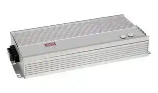
Illustrative purposes only

HEP-1000-100
AC/DC Enclosed Power Supply (PSU), 250 to 431VDC, ITE, 1 Outputs, 1 kW, 100 VDC, 10 A
⚠️ Reference pricing provided. In case of supply shortages, we will connect you with our trusted procurement partners to ensure your project's continuity.
- Manufacturer: MEAN WELL
- Product type: AC / DC Enclosed Power Supplies
- SVHC: No SVHC (25-Jun-2025)
- Product Range: HEP-1000 Series
- No. of Outputs: 1Outputs
- Output Power Max: 1kW
- Input Voltage VAC: 90V AC to 305V AC
- Power Supply Output Type: Adjustable, Fixed
- Output Current - Output 1: 10A
- Output Current - Output 2: -
- Output Current - Output 3: -
- Output Current - Output 4: -
- Output Voltage - Output 1: 100VDC
- Output Voltage - Output 2: -
- Output Voltage - Output 3: -
- Output Voltage - Output 4: -
- Power Supply Applications: ITE
| Delivery and price | |
|---|---|
| Units per pack | 5 |
| Price | 411.26 € |
| Current stock | 10+ |
| Lead time | 30 days |
Datasheet

1000W Switching Power Supply for Harsh Environment **HEP - 1000 series**

**==> picture [254 x 46] intentionally omitted <==**

**----- Start of picture text -----**<br>
IP67 www.IDBauarSicherheitbeegelod2000000000wacmatuv.comt geprufto ges g<br>(Optional) [&®]  cA UL62368-1 [ US] E EN62368-1 N E TPTC004 EAL C IEC62368-1  B C €<br>■ Features<br>**----- End of picture text -----**<br>


## ■

■

℃

Industrial automation machinery Industrial control system Mechanical and electrical equipment Electronic instruments, equipments or apparatus Household appliances

## ■

HEP-1000 is a 1000W industrial AC/DC power supply featuring the outstanding capability to operate under highly humid, dusty, oily, and high-vibration harsh environment. The entire series is housed with the aluminum case and fully potted with heat-conducted silicone.Adopting the full range 90~305VAC input, the entire series provides an output voltage line of 24V, 48V and 100V. In addition to the high efficiency up to 96%, that the whole series operates from -40℃~ 70℃ under air convection without fan. HEP-1000 has the complete protection functions and 10G anti-vibration capability ; It is complied with the international safety regulations such as TUV EN62368-1 UL62368-1, and the design refers to EN61558-1 and EN60335-1 HEP-1000 series serves as a high performance power supply solution for various industrial applications.

## ■

_File Name:HEP-1000-SPEC   2019-11-15_

**- HEP 1000 series**

1000W Switching Power Supply for Harsh Environment

## **SPECIFICATION FOR POWER SUPPLY**

|105~125% rated output power<br>**OVER TEMPERATURE**<br>**DIMENSION**<br>**OTHERS**<br>**NOTE**<br>**OVERLOAD**<br>**OVER VOLTAGE**<br>197.9K hrs min.<br>Telcordia SR-332 (Bellcore) ; 52.32K hrs min.      MIL-HDBK-217F (25<br>)<br>℃<br>℃<br>ncludes set up tolerance,<br>derating curve<br>℃<br>℃<br>**PROTECTION**<br>310*144*48.5mm (L*W*H)<br>Protection type :Shut down O/P voltage,re-power on to recover<br>Protection type :Shut down O/P voltage, recovers automatically after temperature goes down<br>4Kg;4pcs/17Kg/1.04CUFT<br>Protection type : Constant current limiting, unit will shutdown after 5 sec, re-power on to recover.<br>**FUNCTION**<br>**REMOTE ON/OFF CONTROL**<br>**AUXILIARY POWER**<br>**DC-OK SIGNAL**<br>Power ON :  Short circuit          Power OFF : Open circuit<br>12V @ 0.5A tolerance 10%, ripple=150mVp-p<br>±<br>The TTL signal out, PSU turn on = 4.4 ~ 5.5V ; PSU turn off = -0.5 ~ 0.5V. Please refer to the Function Manual.<br>**SAFETY STANDARDS**<br>**SAFETY &**<br>**EMC**<br>**(Note.6)**<br>**WITHSTAND VOLTAGE**<br>**ISOLATION RESISTANCE**<br>I/P-O/P:3KVAC     I/P-FG:2KVAC     O/P-FG:1.25KVAC<br>I/P-O/P, I/P-FG,O/P-FG:100M Ohms/500VDC/25<br>/ 70%RH<br>℃<br>UL62368-1,TUV EN62368-1, EAC TP TC 004 approved; design refer to EN61558-1, EN60335-1(by request)<br>**MTBF**<br>**PACKING**<br>Adjustment of output voltage is allowable to 50 ~ 125% of nominal output voltage<br>Please refer to the Function Manual.<br>Adjustment of constant current level is allowable to 20 ~ 100% of rated current.<br>Please refer to the Function Manual.<br>**OUTPUT VOLTAGE**<br>**PROGRAMMABLE(PV) Note 5**<br>**OUTPUT CURRENT**<br>**PROGRAMMABLE(PC) Note 5**<br>**SHORT CIRCUIT**<br>Constant current limiting, unit will shutdown after 5 sec, re-power on to recover.<br>**MODEL**<br>**DC VOLTAGE**<br>**RATED CURRENT**<br>**RATED POWER**<br>**OUTPUT**<br>**VOLTAGE ADJ. RANGE**<br>**LINE REGULATION**<br>**LOAD REGULATION**<br>**SETUP, RISE TIME**<br>**HOLD UP TIME (Typ.)**<br>**VOLTAGE RANGE**<br>**Note.4**<br>**FREQUENCY RANGE**<br>**POWER FACTOR (Typ.)**<br>**EFFICIENCY (Typ.)**<br>**AC CURRENT (Typ.)**<br>**INPUT**<br>**INRUSH CURRENT(Typ.)**<br>**LEAKAGE CURRENT**<br>1800ms, 80ms at full load         230VAC /115VAC<br>16ms / 230VAC at 75% load      12ms / 230VAC at full load<br>90 ~ 305VAC          250 ~ 431VDC<br>47 ~ 63Hz<br>PF>0.99/115VAC, PF>0.95/230VAC, PF>0.93/277VAC at full load<br>10.1A / 115VAC          5.3A / 230VAC          4.5A / 277VAC<br><0.75mA / 240VAC<br>**RIPPLE & NOISE (max.) Note.2**<br>**VOLTAGE TOLERANCE Note.3**<br>95%<br>96%<br>±1.0%<br>±1.0%<br>±1.0%<br>±0.5%<br>±0.5%<br>±0.5%<br>±0.5%<br>±0.5%<br>±0.5%<br>**HEP-1000-24**<br>**HEP-1000-100**<br>**HEP-1000-48**<br>24V<br>100V<br>48V<br>42A<br>10A<br>21A<br>1008W<br>1000W<br>1008W<br>200mVp-p<br>24 ~ 30V<br>500mVp-p<br>250mVp-p<br>100 ~ 125V<br>48 ~ 60V<br>Cold start 40A at 230VAC<br>96%<br>**WORKING TEMP.**<br>**WORKING HUMIDITY**<br>**STORAGE TEMP., HUMIDITY**<br>**TEMP. COEFFICIENT**<br>**VIBRATION**<br>-40 ~ +70<br>(Refer to "Derating Curve")<br>℃<br>20 ~ 95% RH non-condensing<br>-40 ~ +80<br>, 10 ~ 95% RH<br>℃<br>non-condensing<br>±<br>℃<br>℃<br>0.03%/<br>(0 ~ 50<br>)<br>20 ~ 500Hz, 10G 12min./1cycle, period for  72min. each along X, Y, Z axes<br>**ENVIRONMENT**<br>By built-in potentiometer, SVR<br>125 ~ 145V<br>30 ~ 35V<br>60 ~ 70V<br>**EMC IMMUNITY**<br>**EMC EMISSION**<br>**Parameter**<br>**Parameter**<br>ESD<br>Radiated<br>EFT / Burst<br>Surge<br>Conducted<br>Magnetic Field<br>Voltage Dips and Interruptions<br>Conducted<br>Radiated<br>Harmonic Current<br>Voltage Flicker<br>EN55024 , EN61000-6-2<br>**Standard**<br>**Standard**<br>EN55032 (CISPR32)<br>EN55032 (CISPR32)<br>EN61000-3-2<br>EN61000-3-3<br>EN61000-4-2<br>EN61000-4-3<br>EN61000-4-4<br>EN61000-6-2<br>EN61000-4-6<br>EN61000-4-8<br>EN61000-4-11<br>**Test Level / Note**<br>**Test Level / Note**<br>Level 3, 8KV air ; Level 2, 4KV contact<br>Level 3<br>Level 3<br>2KV/Line-Line 4KV/Line-Earth<br>Level 3<br>Level 4<br>>95% dip 0.5 periods, 30% dip 25 periods,<br>>95% interruptions 250 periods<br>Class B<br>Class B<br>Class A<br>-----<br>~~ee~~<br>1. All parameters NOT specially mentioned are measured at230VAC input, rated load and 25 _ ofambient temperature.<br>2. Ripple & noise are measured at 20MHz of bandwidth by using a 12" twisted pair-wire terminated with a 0.1uf & 47uf parallel capacitor.<br>3. Tolerance<br>line regulation and load regulation.<br>4. Derating may be needed under low input voltages. Please check the<br>for more details.<br>5. PV/PC functions when users do not use SVR.<br>6. The power supply is considered a component which will be installed into a final equipment. All the EMC tests are been executed by mounting the unit on<br>a 720mm*360mm metal plate with 1mm of thickness. The final equipment must be re-confirmed that it still meets EMC directives. For guidance on how to<br>perform these EMC tests, please refer to “EMI testing of component power supplies.” (as available on http://www.meanwell.com)<br>7. The ambient temperature derating of 3.5<br>/1000m with fanless models and of<br>5<br>/1000m with fan models for operating altitude higher than 2000m(6500ft).|105~125% rated output power<br>**OVER TEMPERATURE**<br>**DIMENSION**<br>**OTHERS**<br>**NOTE**<br>**OVERLOAD**<br>**OVER VOLTAGE**<br>197.9K hrs min.<br>Telcordia SR-332 (Bellcore) ; 52.32K hrs min.      MIL-HDBK-217F (25<br>)<br>℃<br>℃<br>ncludes set up tolerance,<br>derating curve<br>℃<br>℃<br>**PROTECTION**<br>310*144*48.5mm (L*W*H)<br>Protection type :Shut down O/P voltage,re-power on to recover<br>Protection type :Shut down O/P voltage, recovers automatically after temperature goes down<br>4Kg;4pcs/17Kg/1.04CUFT<br>Protection type : Constant current limiting, unit will shutdown after 5 sec, re-power on to recover.<br>**FUNCTION**<br>**REMOTE ON/OFF CONTROL**<br>**AUXILIARY POWER**<br>**DC-OK SIGNAL**<br>Power ON :  Short circuit          Power OFF : Open circuit<br>12V @ 0.5A tolerance 10%, ripple=150mVp-p<br>±<br>The TTL signal out, PSU turn on = 4.4 ~ 5.5V ; PSU turn off = -0.5 ~ 0.5V. Please refer to the Function Manual.<br>**SAFETY STANDARDS**<br>**SAFETY &**<br>**EMC**<br>**(Note.6)**<br>**WITHSTAND VOLTAGE**<br>**ISOLATION RESISTANCE**<br>I/P-O/P:3KVAC     I/P-FG:2KVAC     O/P-FG:1.25KVAC<br>I/P-O/P, I/P-FG,O/P-FG:100M Ohms/500VDC/25<br>/ 70%RH<br>℃<br>UL62368-1,TUV EN62368-1, EAC TP TC 004 approved; design refer to EN61558-1, EN60335-1(by request)<br>**MTBF**<br>**PACKING**<br>Adjustment of output voltage is allowable to 50 ~ 125% of nominal output voltage<br>Please refer to the Function Manual.<br>Adjustment of constant current level is allowable to 20 ~ 100% of rated current.<br>Please refer to the Function Manual.<br>**OUTPUT VOLTAGE**<br>**PROGRAMMABLE(PV) Note 5**<br>**OUTPUT CURRENT**<br>**PROGRAMMABLE(PC) Note 5**<br>**SHORT CIRCUIT**<br>Constant current limiting, unit will shutdown after 5 sec, re-power on to recover.<br>**MODEL**<br>**DC VOLTAGE**<br>**RATED CURRENT**<br>**RATED POWER**<br>**OUTPUT**<br>**VOLTAGE ADJ. RANGE**<br>**LINE REGULATION**<br>**LOAD REGULATION**<br>**SETUP, RISE TIME**<br>**HOLD UP TIME (Typ.)**<br>**VOLTAGE RANGE**<br>**Note.4**<br>**FREQUENCY RANGE**<br>**POWER FACTOR (Typ.)**<br>**EFFICIENCY (Typ.)**<br>**AC CURRENT (Typ.)**<br>**INPUT**<br>**INRUSH CURRENT(Typ.)**<br>**LEAKAGE CURRENT**<br>1800ms, 80ms at full load         230VAC /115VAC<br>16ms / 230VAC at 75% load      12ms / 230VAC at full load<br>90 ~ 305VAC          250 ~ 431VDC<br>47 ~ 63Hz<br>PF>0.99/115VAC, PF>0.95/230VAC, PF>0.93/277VAC at full load<br>10.1A / 115VAC          5.3A / 230VAC          4.5A / 277VAC<br><0.75mA / 240VAC<br>**RIPPLE & NOISE (max.) Note.2**<br>**VOLTAGE TOLERANCE Note.3**<br>95%<br>96%<br>±1.0%<br>±1.0%<br>±1.0%<br>±0.5%<br>±0.5%<br>±0.5%<br>±0.5%<br>±0.5%<br>±0.5%<br>**HEP-1000-24**<br>**HEP-1000-100**<br>**HEP-1000-48**<br>24V<br>100V<br>48V<br>42A<br>10A<br>21A<br>1008W<br>1000W<br>1008W<br>200mVp-p<br>24 ~ 30V<br>500mVp-p<br>250mVp-p<br>100 ~ 125V<br>48 ~ 60V<br>Cold start 40A at 230VAC<br>96%<br>**WORKING TEMP.**<br>**WORKING HUMIDITY**<br>**STORAGE TEMP., HUMIDITY**<br>**TEMP. COEFFICIENT**<br>**VIBRATION**<br>-40 ~ +70<br>(Refer to "Derating Curve")<br>℃<br>20 ~ 95% RH non-condensing<br>-40 ~ +80<br>, 10 ~ 95% RH<br>℃<br>non-condensing<br>±<br>℃<br>℃<br>0.03%/<br>(0 ~ 50<br>)<br>20 ~ 500Hz, 10G 12min./1cycle, period for  72min. each along X, Y, Z axes<br>**ENVIRONMENT**<br>By built-in potentiometer, SVR<br>125 ~ 145V<br>30 ~ 35V<br>60 ~ 70V<br>**EMC IMMUNITY**<br>**EMC EMISSION**<br>**Parameter**<br>**Parameter**<br>ESD<br>Radiated<br>EFT / Burst<br>Surge<br>Conducted<br>Magnetic Field<br>Voltage Dips and Interruptions<br>Conducted<br>Radiated<br>Harmonic Current<br>Voltage Flicker<br>EN55024 , EN61000-6-2<br>**Standard**<br>**Standard**<br>EN55032 (CISPR32)<br>EN55032 (CISPR32)<br>EN61000-3-2<br>EN61000-3-3<br>EN61000-4-2<br>EN61000-4-3<br>EN61000-4-4<br>EN61000-6-2<br>EN61000-4-6<br>EN61000-4-8<br>EN61000-4-11<br>**Test Level / Note**<br>**Test Level / Note**<br>Level 3, 8KV air ; Level 2, 4KV contact<br>Level 3<br>Level 3<br>2KV/Line-Line 4KV/Line-Earth<br>Level 3<br>Level 4<br>>95% dip 0.5 periods, 30% dip 25 periods,<br>>95% interruptions 250 periods<br>Class B<br>Class B<br>Class A<br>-----<br>~~ee~~<br>1. All parameters NOT specially mentioned are measured at230VAC input, rated load and 25 _ ofambient temperature.<br>2. Ripple & noise are measured at 20MHz of bandwidth by using a 12" twisted pair-wire terminated with a 0.1uf & 47uf parallel capacitor.<br>3. Tolerance<br>line regulation and load regulation.<br>4. Derating may be needed under low input voltages. Please check the<br>for more details.<br>5. PV/PC functions when users do not use SVR.<br>6. The power supply is considered a component which will be installed into a final equipment. All the EMC tests are been executed by mounting the unit on<br>a 720mm*360mm metal plate with 1mm of thickness. The final equipment must be re-confirmed that it still meets EMC directives. For guidance on how to<br>perform these EMC tests, please refer to “EMI testing of component power supplies.” (as available on http://www.meanwell.com)<br>7. The ambient temperature derating of 3.5<br>/1000m with fanless models and of<br>5<br>/1000m with fan models for operating altitude higher than 2000m(6500ft).|**HEP-1000-24**|**HEP-1000-48**|**HEP-1000-100**|
|---|---|---|---|---|
||**DC VOLTAGE**|24V|48V|100V|
||**RATED CURRENT**|42A|21A|10A|
||**RATED POWER**|1008W|1008W|1000W|
||**RIPPLE & NOISE (max.) Note.2**|200mVp-p|250mVp-p|500mVp-p|
||**VOLTAGE ADJ. RANGE**|24 ~ 30V<br>100 ~ 125V<br>48 ~ 60V<br>By built-in potentiometer, SVR|||
||**VOLTAGE TOLERANCE Note.3**|±1.0%|±1.0%|±1.0%|
||**LINE REGULATION**|±0.5%|±0.5%|±0.5%|
||**LOAD REGULATION**|±0.5%|±0.5%|±0.5%|
||**SETUP, RISE TIME**|1800ms, 80ms at full load         230VAC /115VAC|||
||**HOLD UP TIME (Typ.)**|16ms / 230VAC at 75% load      12ms / 230VAC at full load|||
||**VOLTAGE RANGE**<br>**Note.4**|90 ~ 305VAC          250 ~ 431VDC|||
||**FREQUENCY RANGE**|47 ~ 63Hz|||
||**POWER FACTOR (Typ.)**|PF>0.99/115VAC, PF>0.95/230VAC, PF>0.93/277VAC at full load|||
||**EFFICIENCY (Typ.)**|95%|96%|96%|
||**AC CURRENT (Typ.)**|10.1A / 115VAC          5.3A / 230VAC          4.5A / 277VAC|||
||**INRUSH CURRENT(Typ.)**|Cold start 40A at 230VAC|||
||**LEAKAGE CURRENT**|<0.75mA / 240VAC|||
||**OVERLOAD**|105~125% rated output power<br>Protection type : Constant current limiting, unit will shutdown after 5 sec, re-power on to recover.|||
||**SHORT CIRCUIT**|Constant current limiting, unit will shutdown after 5 sec, re-power on to recover.|||
||**OVER VOLTAGE**|Protection type :Shut down O/P voltage,re-power on to recover<br>125 ~ 145V<br>30 ~ 35V<br>60 ~ 70V|||
||**OVER TEMPERATURE**|Protection type :Shut down O/P voltage, recovers automatically after temperature goes down|||
||**OUTPUT VOLTAGE**<br>**PROGRAMMABLE(PV) Note 5**|Adjustment of output voltage is allowable to 50 ~ 125% of nominal output voltage<br>Please refer to the Function Manual.|||
||**OUTPUT CURRENT**<br>**PROGRAMMABLE(PC) Note 5**|Adjustment of constant current level is allowable to 20 ~ 100% of rated current.<br>Please refer to the Function Manual.|||
||**REMOTE ON/OFF CONTROL**|Power ON :  Short circuit          Power OFF : Open circuit|||
||**AUXILIARY POWER**|12V @ 0.5A tolerance 10%, ripple=150mVp-p<br>±|||
||**DC-OK SIGNAL**|The TTL signal out, PSU turn on = 4.4 ~ 5.5V ; PSU turn off = -0.5 ~ 0.5V. Please refer to the Function Manual.|||
||**WORKING TEMP.**|-40 ~ +70<br>(Refer to "Derating Curve")<br>℃|||
||**WORKING HUMIDITY**|20 ~ 95% RH non-condensing|||
||**STORAGE TEMP., HUMIDITY**|-40 ~ +80<br>, 10 ~ 95% RH<br>℃<br>non-condensing|||
||**TEMP. COEFFICIENT**|±<br>℃<br>℃<br>0.03%/<br>(0 ~ 50<br>)|||
||**VIBRATION**|20 ~ 500Hz, 10G 12min./1cycle, period for  72min. each along X, Y, Z axes|||
||**SAFETY STANDARDS**|UL62368-1,TUV EN62368-1, EAC TP TC 004 approved; design refer to EN61558-1, EN60335-1(by request)|||
||**WITHSTAND VOLTAGE**|I/P-O/P:3KVAC     I/P-FG:2KVAC     O/P-FG:1.25KVAC|||
||**ISOLATION RESISTANCE**<br>**EMC IMMUNITY**<br>**EMC EMISSION**<br>~~ee~~|I/P-O/P, I/P-FG,O/P-FG:100M Ohms/500VDC/25<br>/ 70%RH<br>℃|||
|||**Parameter**|**Standard**|**Test Level / Note**|
|||Conducted|EN55032 (CISPR32)|Class B|
|||Radiated|EN55032 (CISPR32)|Class B|
|||Harmonic Current|EN61000-3-2|Class A|
|||Voltage Flicker|EN61000-3-3|-----|
|||EN55024 , EN61000-6-2|||
|||**Parameter**|**Standard**|**Test Level / Note**|
|||ESD|EN61000-4-2|Level 3, 8KV air ; Level 2, 4KV contact|
|||Radiated|EN61000-4-3|Level 3|
|||EFT / Burst|EN61000-4-4|Level 3|
|||Surge|EN61000-6-2|2KV/Line-Line 4KV/Line-Earth|
|||Conducted|EN61000-4-6|Level 3|
|||Magnetic Field|EN61000-4-8|Level 4|
|||Voltage Dips and Interruptions<br>~~ee~~|EN61000-4-11<br>~~ee~~|>95% dip 0.5 periods, 30% dip 25 periods,<br>>95% interruptions 250 periods<br>~~ee~~|
||**MTBF**<br>~~ee~~|197.9K hrs min.<br>Telcordia SR-332 (Bellcore) ; 52.32K hrs min.      MIL-HDBK-217F (25<br>)<br>℃<br>~~ee~~|||
||**DIMENSION**<br>~~ee~~|310*144*48.5mm (L*W*H)<br>~~ee~~|||
||**PACKING**<br>~~ee~~|4Kg;4pcs/17Kg/1.04CUFT<br>~~ee~~|||
||℃<br>ncludes set up tolerance,<br>derating curve<br>℃<br>℃<br>~~ee~~<br>1. All parameters NOT specially mentioned are measured at230VAC input, rated load and 25 _ ofambient temperature.<br>2. Ripple & noise are measured at 20MHz of bandwidth by using a 12" twisted pair-wire terminated with a 0.1uf & 47uf parallel capacitor.<br>3. Tolerance<br>line regulation and load regulation.<br>4. Derating may be needed under low input voltages. Please check the<br>for more details.<br>5. PV/PC functions when users do not use SVR.<br>6. The power supply is considered a component which will be installed into a final equipment. All the EMC tests are been executed by mounting the unit on<br>a 720mm*360mm metal plate with 1mm of thickness. The final equipment must be re-confirmed that it still meets EMC directives. For guidance on how to<br>perform these EMC tests, please refer to “EMI testing of component power supplies.” (as available on http://www.meanwell.com)<br>7. The ambient temperature derating of 3.5<br>/1000m with fanless models and of<br>5<br>/1000m with fan models for operating altitude higher than 2000m(6500ft).||||


derating curve

℃ /1000m with fanless models and of 5 ℃

_File Name:HEP-1000-SPEC   2019-11-15_

1000W Switching Power Supply for Harsh Environment **HEP - 1000 series** ~~seen~~ ee ee ree rere ee ee ee ee

## **SPECIFICATION FOR CHARGER**

|**HEP-1000-24**<br>**HEP-1000-48**<br>**HEP-1000-100**<br>**MODEL**<br>**BOOST CHARGE  VOLTAGE Vboost**<br>**FLOAT CHARGE  VOLTAGE Vfloat**<br>**OUTPUT CURRENT**<br>**BATTERY TYPE**<br>**RECOMMENDED BATTERY**<br>**CAPACITY(AMP HOURS)(Note 2)**<br>**OUTPUT**<br>28.8V<br>57.6V<br>115.2V<br>27.6V<br>35A<br>Open & Sealed Lead Acid<br>120 ~ 350AH<br>55.2V<br>110.4V<br>17.5A<br>8.7A<br>60 ~ 175AH<br>30 ~ 85AH<br>30 ~ 35V<br>60 ~ 70V<br>**EMC IMMUNITY**<br>**EMC EMISSION**<br>**Parameter**<br>**Parameter**<br>ESD<br>Radiated<br>EFT / Burst<br>Surge<br>Conducted<br>Magnetic Field<br>Voltage Dips and Interruptions<br>Conducted<br>Radiated<br>Harmonic Current<br>Voltage Flicker<br>EN55024 , EN61000-6-2<br>**Standard**<br>**Standard**<br>EN55032 (CISPR32)<br>EN55032 (CISPR32)<br>EN61000-3-2<br>EN61000-3-3<br>EN61000-4-2<br>EN61000-4-3<br>EN61000-4-4<br>EN61000-6-2<br>EN61000-4-6<br>EN61000-4-8<br>EN61000-4-11<br>**Test Level / Note**<br>**Test Level / Note**<br>Level 3, 8KV air ; Level 2, 4KV contact<br>Level 3<br>Level 3<br>2KV/Line-Line 4KV/Line-Earth<br>Level 3<br>Level 4<br>>95% dip 0.5 periods, 30% dip 25 periods,<br>>95% interruptions 250 periods<br>Class B<br>Class A<br>Class A<br>-----<br>**OVER TEMPERATURE**<br>**DIMENSION**<br>**OTHERS**<br>**NOTE**<br>**OVER VOLTAGE**<br>197.9K hrs min.<br>Telcordia SR-332 (Bellcore) ; 52.32K hrs min.      MIL-HDBK-217F (25<br>)<br>℃<br>℃<br>derating curve<br>℃<br>℃<br>**PROTECTION**<br>310*144*48.5mm (L*W*H)<br>Protection type :Shut down O/P voltage,re-power on to recover<br>Protection type :Shut down O/P voltage, recovers automatically after temperature goes down<br>4Kg;4pcs/17Kg/1.04CUFT<br>**FUNCTION**<br>**REMOTE ON/OFF CONTROL**<br>**AUXILIARY POWER**<br>**DC-OK SIGNAL**<br>Power ON :  Short circuit          Power OFF : Open circuit<br>12V @ 0.5A tolerance 10%, ripple=150mVp-p<br>±<br>The TTL signal out, PSU turn on = 4.4 ~ 5.5V ; PSU turn off = -0.5 ~ 0.5V. Please refer to the Function Manual.<br>**SAFETY STANDARDS**<br>**SAFETY &**<br>**EMC**<br>**(Note.4)**<br>**WITHSTAND VOLTAGE**<br>**ISOLATION RESISTANCE**<br>I/P-O/P:3KVAC     I/P-FG:2KVAC     O/P-FG:1.25KVAC<br>I/P-O/P, I/P-FG,O/P-FG:100M Ohms/500VDC/25<br>/ 70%RH<br>℃<br>UL62368-1,TUV EN62368-1, EAC TP TC 004 approved; design refer to EN61558-1, EN60335-1(by request)<br>**MTBF**<br>**PACKING**<br>**VOLTAGE RANGE**<br>**Note 3**<br>**FREQUENCY RANGE**<br>**POWER FACTOR (Typ.)**<br>**EFFICIENCY (Typ.)**<br>**AC CURRENT (Typ.)**<br>**INPUT**<br>**INRUSH CURRENT(Typ.)**<br>**LEAKAGE CURRENT**<br>90 ~ 305VAC          250 ~ 431VDC<br>47 ~ 63Hz<br>PF>0.99/115VAC, PF>0.95/230VAC, PF>0.93/277VAC at full load<br>10.1A / 115VAC          5.3A / 230VAC          4.5A / 277VAC<br><0.75mA / 240VAC<br>95%<br>96%<br>Cold start 40A at 230VAC<br>96%<br>**WORKING TEMP.**<br>**WORKING HUMIDITY**<br>**STORAGE TEMP., HUMIDITY**<br>**TEMP. COEFFICIENT**<br>**VIBRATION**<br>-40 ~ +70<br>(Refer to "Derating Curve")<br>℃<br>20 ~ 95% RH non-condensing<br>-40 ~ +80<br>, 10 ~ 95% RH<br>℃<br>non-condensing<br>±<br>℃<br>℃<br>0.03%/<br>(0 ~ 50<br>)<br>20 ~ 500Hz, 10G 12min./1cycle, period for  72min. each along X, Y, Z axes<br>**ENVIRONMENT**<br>125 ~ 145V<br>**SHORT CIRCUIT**<br>Constant current limiting, unit will shutdown after 5 sec, re-power on to recover.<br>1. All parameters NOT specially mentioned are measured at230VAC input, rated load and 25 _ ofambient temperature.<br>2. This is Mean Well's suggested range. Please consult your battery manufacturer for their suggestions about maximum charging current limitation.<br>3. Derating may be needed under low input voltages. Please check the<br>for more details.<br>4. The power supply is considered a component which will be installed into a final equipment. All the EMC tests are been executed by mounting the unit on<br>a 720mm*360mm metal plate with 1mm of thickness. The final equipment must be re-confirmed that it still meets EMC directives. For guidance on how to<br>perform these EMC tests, please refer to “EMI testing of component power supplies.” (as available on http://www.meanwell.com)<br>5. The ambient temperature derating of 3.5<br>/1000m with fanless models and of<br>5<br>/1000m with fan models for operating altitude higher than 2000m(6500ft).|**HEP-1000-24**<br>**HEP-1000-48**<br>**HEP-1000-100**<br>**MODEL**<br>**BOOST CHARGE  VOLTAGE Vboost**<br>**FLOAT CHARGE  VOLTAGE Vfloat**<br>**OUTPUT CURRENT**<br>**BATTERY TYPE**<br>**RECOMMENDED BATTERY**<br>**CAPACITY(AMP HOURS)(Note 2)**<br>**OUTPUT**<br>28.8V<br>57.6V<br>115.2V<br>27.6V<br>35A<br>Open & Sealed Lead Acid<br>120 ~ 350AH<br>55.2V<br>110.4V<br>17.5A<br>8.7A<br>60 ~ 175AH<br>30 ~ 85AH<br>30 ~ 35V<br>60 ~ 70V<br>**EMC IMMUNITY**<br>**EMC EMISSION**<br>**Parameter**<br>**Parameter**<br>ESD<br>Radiated<br>EFT / Burst<br>Surge<br>Conducted<br>Magnetic Field<br>Voltage Dips and Interruptions<br>Conducted<br>Radiated<br>Harmonic Current<br>Voltage Flicker<br>EN55024 , EN61000-6-2<br>**Standard**<br>**Standard**<br>EN55032 (CISPR32)<br>EN55032 (CISPR32)<br>EN61000-3-2<br>EN61000-3-3<br>EN61000-4-2<br>EN61000-4-3<br>EN61000-4-4<br>EN61000-6-2<br>EN61000-4-6<br>EN61000-4-8<br>EN61000-4-11<br>**Test Level / Note**<br>**Test Level / Note**<br>Level 3, 8KV air ; Level 2, 4KV contact<br>Level 3<br>Level 3<br>2KV/Line-Line 4KV/Line-Earth<br>Level 3<br>Level 4<br>>95% dip 0.5 periods, 30% dip 25 periods,<br>>95% interruptions 250 periods<br>Class B<br>Class A<br>Class A<br>-----<br>**OVER TEMPERATURE**<br>**DIMENSION**<br>**OTHERS**<br>**NOTE**<br>**OVER VOLTAGE**<br>197.9K hrs min.<br>Telcordia SR-332 (Bellcore) ; 52.32K hrs min.      MIL-HDBK-217F (25<br>)<br>℃<br>℃<br>derating curve<br>℃<br>℃<br>**PROTECTION**<br>310*144*48.5mm (L*W*H)<br>Protection type :Shut down O/P voltage,re-power on to recover<br>Protection type :Shut down O/P voltage, recovers automatically after temperature goes down<br>4Kg;4pcs/17Kg/1.04CUFT<br>**FUNCTION**<br>**REMOTE ON/OFF CONTROL**<br>**AUXILIARY POWER**<br>**DC-OK SIGNAL**<br>Power ON :  Short circuit          Power OFF : Open circuit<br>12V @ 0.5A tolerance 10%, ripple=150mVp-p<br>±<br>The TTL signal out, PSU turn on = 4.4 ~ 5.5V ; PSU turn off = -0.5 ~ 0.5V. Please refer to the Function Manual.<br>**SAFETY STANDARDS**<br>**SAFETY &**<br>**EMC**<br>**(Note.4)**<br>**WITHSTAND VOLTAGE**<br>**ISOLATION RESISTANCE**<br>I/P-O/P:3KVAC     I/P-FG:2KVAC     O/P-FG:1.25KVAC<br>I/P-O/P, I/P-FG,O/P-FG:100M Ohms/500VDC/25<br>/ 70%RH<br>℃<br>UL62368-1,TUV EN62368-1, EAC TP TC 004 approved; design refer to EN61558-1, EN60335-1(by request)<br>**MTBF**<br>**PACKING**<br>**VOLTAGE RANGE**<br>**Note 3**<br>**FREQUENCY RANGE**<br>**POWER FACTOR (Typ.)**<br>**EFFICIENCY (Typ.)**<br>**AC CURRENT (Typ.)**<br>**INPUT**<br>**INRUSH CURRENT(Typ.)**<br>**LEAKAGE CURRENT**<br>90 ~ 305VAC          250 ~ 431VDC<br>47 ~ 63Hz<br>PF>0.99/115VAC, PF>0.95/230VAC, PF>0.93/277VAC at full load<br>10.1A / 115VAC          5.3A / 230VAC          4.5A / 277VAC<br><0.75mA / 240VAC<br>95%<br>96%<br>Cold start 40A at 230VAC<br>96%<br>**WORKING TEMP.**<br>**WORKING HUMIDITY**<br>**STORAGE TEMP., HUMIDITY**<br>**TEMP. COEFFICIENT**<br>**VIBRATION**<br>-40 ~ +70<br>(Refer to "Derating Curve")<br>℃<br>20 ~ 95% RH non-condensing<br>-40 ~ +80<br>, 10 ~ 95% RH<br>℃<br>non-condensing<br>±<br>℃<br>℃<br>0.03%/<br>(0 ~ 50<br>)<br>20 ~ 500Hz, 10G 12min./1cycle, period for  72min. each along X, Y, Z axes<br>**ENVIRONMENT**<br>125 ~ 145V<br>**SHORT CIRCUIT**<br>Constant current limiting, unit will shutdown after 5 sec, re-power on to recover.<br>1. All parameters NOT specially mentioned are measured at230VAC input, rated load and 25 _ ofambient temperature.<br>2. This is Mean Well's suggested range. Please consult your battery manufacturer for their suggestions about maximum charging current limitation.<br>3. Derating may be needed under low input voltages. Please check the<br>for more details.<br>4. The power supply is considered a component which will be installed into a final equipment. All the EMC tests are been executed by mounting the unit on<br>a 720mm*360mm metal plate with 1mm of thickness. The final equipment must be re-confirmed that it still meets EMC directives. For guidance on how to<br>perform these EMC tests, please refer to “EMI testing of component power supplies.” (as available on http://www.meanwell.com)<br>5. The ambient temperature derating of 3.5<br>/1000m with fanless models and of<br>5<br>/1000m with fan models for operating altitude higher than 2000m(6500ft).|**HEP-1000-24**|**HEP-1000-48**|**HEP-1000-100**|
|---|---|---|---|---|
||**BOOST CHARGE  VOLTAGE Vboost**|28.8V|57.6V|115.2V|
||**FLOAT CHARGE  VOLTAGE Vfloat**|27.6V|55.2V|110.4V|
||**RECOMMENDED BATTERY**<br>**CAPACITY(AMP HOURS)(Note 2)**|120 ~ 350AH|60 ~ 175AH|30 ~ 85AH|
||**BATTERY TYPE**|Open & Sealed Lead Acid|||
||**OUTPUT CURRENT**|35A|17.5A|8.7A|
||**VOLTAGE RANGE**<br>**Note 3**|90 ~ 305VAC          250 ~ 431VDC|||
||**FREQUENCY RANGE**|47 ~ 63Hz|||
||**POWER FACTOR (Typ.)**|PF>0.99/115VAC, PF>0.95/230VAC, PF>0.93/277VAC at full load|||
||**EFFICIENCY (Typ.)**|95%|96%|96%|
||**AC CURRENT (Typ.)**|10.1A / 115VAC          5.3A / 230VAC          4.5A / 277VAC|||
||**INRUSH CURRENT(Typ.)**|Cold start 40A at 230VAC|||
||**LEAKAGE CURRENT**|<0.75mA / 240VAC|||
||**SHORT CIRCUIT**|Constant current limiting, unit will shutdown after 5 sec, re-power on to recover.|||
||**OVER VOLTAGE**|30 ~ 35V<br>60 ~ 70V<br>Protection type :Shut down O/P voltage,re-power on to recover<br>125 ~ 145V|||
||**OVER TEMPERATURE**|Protection type :Shut down O/P voltage, recovers automatically after temperature goes down|||
||**REMOTE ON/OFF CONTROL**|Power ON :  Short circuit          Power OFF : Open circuit|||
||**AUXILIARY POWER**|12V @ 0.5A tolerance 10%, ripple=150mVp-p<br>±|||
||**DC-OK SIGNAL**|The TTL signal out, PSU turn on = 4.4 ~ 5.5V ; PSU turn off = -0.5 ~ 0.5V. Please refer to the Function Manual.|||
||**WORKING TEMP.**|-40 ~ +70<br>(Refer to "Derating Curve")<br>℃|||
||**WORKING HUMIDITY**|20 ~ 95% RH non-condensing|||
||**STORAGE TEMP., HUMIDITY**|-40 ~ +80<br>, 10 ~ 95% RH<br>℃<br>non-condensing|||
||**TEMP. COEFFICIENT**|±<br>℃<br>℃<br>0.03%/<br>(0 ~ 50<br>)|||
||**VIBRATION**|20 ~ 500Hz, 10G 12min./1cycle, period for  72min. each along X, Y, Z axes|||
||**SAFETY STANDARDS**|UL62368-1,TUV EN62368-1, EAC TP TC 004 approved; design refer to EN61558-1, EN60335-1(by request)|||
||**WITHSTAND VOLTAGE**|I/P-O/P:3KVAC     I/P-FG:2KVAC     O/P-FG:1.25KVAC|||
||**EMC IMMUNITY**<br>**EMC EMISSION**<br>**ISOLATION RESISTANCE**|I/P-O/P, I/P-FG,O/P-FG:100M Ohms/500VDC/25<br>/ 70%RH<br>℃|||
|||**Parameter**|**Standard**|**Test Level / Note**|
|||Conducted|EN55032 (CISPR32)|Class B|
|||Radiated|EN55032 (CISPR32)|Class A|
|||Harmonic Current|EN61000-3-2|Class A|
|||Voltage Flicker|EN61000-3-3|-----|
|||EN55024 , EN61000-6-2|||
|||**Parameter**|**Standard**|**Test Level / Note**|
|||ESD|EN61000-4-2|Level 3, 8KV air ; Level 2, 4KV contact|
|||Radiated|EN61000-4-3|Level 3|
|||EFT / Burst|EN61000-4-4|Level 3|
|||Surge|EN61000-6-2|2KV/Line-Line 4KV/Line-Earth|
|||Conducted|EN61000-4-6|Level 3|
|||Magnetic Field|EN61000-4-8|Level 4|
|||Voltage Dips and Interruptions|EN61000-4-11|>95% dip 0.5 periods, 30% dip 25 periods,<br>>95% interruptions 250 periods|
||**MTBF**|197.9K hrs min.<br>Telcordia SR-332 (Bellcore) ; 52.32K hrs min.      MIL-HDBK-217F (25<br>)<br>℃|||
||**DIMENSION**|310*144*48.5mm (L*W*H)|||
||**PACKING**|4Kg;4pcs/17Kg/1.04CUFT|||
||℃<br>derating curve<br>℃<br>℃<br>1. All parameters NOT specially mentioned are measured at230VAC input, rated load and 25 _ ofambient temperature.<br>2. This is Mean Well's suggested range. Please consult your battery manufacturer for their suggestions about maximum charging current limitation.<br>3. Derating may be needed under low input voltages. Please check the<br>for more details.<br>4. The power supply is considered a component which will be installed into a final equipment. All the EMC tests are been executed by mounting the unit on<br>a 720mm*360mm metal plate with 1mm of thickness. The final equipment must be re-confirmed that it still meets EMC directives. For guidance on how to<br>perform these EMC tests, please refer to “EMI testing of component power supplies.” (as available on http://www.meanwell.com)<br>5. The ambient temperature derating of 3.5<br>/1000m with fanless models and of<br>5<br>/1000m with fan models for operating altitude higher than 2000m(6500ft).||||


_File Name:HEP-1000-SPEC   2019-11-15_

**- HEP 1000 series**

## 1000W Switching Power Supply for Harsh Environment

## **BLOCK DIAGRAM**

**==> picture [500 x 433] intentionally omitted <==**

**----- Start of picture text -----**<br>
PFC fosc : 70KHz<br>PWM fosc : 65KHz<br>I/P FILTEREMI CURRENTLIMITINGINRUSHACTIVE RECTIFIERSPFC& SWITCHINGPOWER RECTIFIERSFILTER& -V+V<br>O.V.P.<br>DETECTION PV<br>PFC PWM CIRCUIT<br>CONTROL CONTROL PC<br>O.T.P.<br>DETECTION MCU MCU DATA DC OK<br>CIRCUIT ISOLATION Remote ON-OFF<br>O.T.P.<br>PM BUS<br>AUX RECTIFIERS ISOLATIONDATA or<br>POWER & 12V/0.5A CAN BUS<br>FILTER AUX POWER<br>DERATING CURVE STATIC CHARACTERISTICS<br>100<br>100<br>90<br>80 80<br>70<br>60 65<br>60<br>40<br>50<br>40<br>20<br>30<br>-40 -25 -10 0 15 30 50 60 70 (HORIZONTAL) 90 100 115 180 305<br>AMBIENT TEMPERATURE ( ℃ ) INPUT VOLTAGE (V) 60Hz<br>※ For 100V model charging mode, output current is 20% rated min. when operating tempature at -40℃,  and can reach 100% above -30℃.<br>LOAD (%) LOAD (%)<br>**----- End of picture text -----**<br>


_File Name:HEP-1000-SPEC   2019-11-15_

1000W Switching Power Supply for Harsh Environment **HEP - 1000 series**

## **FUNCTION MANUAL**

## **1.Charging Curve**

**==> picture [483 x 274] intentionally omitted <==**

**----- Start of picture text -----**<br>
※ By default, the HEP-1000 operates in power supply mode, and it can be configured to charger mode by PMBus, CANBus, or SBP-001.<br>※ By factory default, this charger performs the default curve which can be programmed via PMBus and CANBus.<br>※ To accommodate the parameters of the charging curve, SBP-001, the smart battery charging programmer designed by MEAN WELL, and a personal<br>computer are needed. Please contact MEAN WELL for details.<br>※ Default 2 stage charging curve ※ Default 3 stage charging curve<br>Start Start<br>Vboost Vboost<br>Vfloat<br>Charge Voltage Charge Voltage<br>100% 100%<br>10% 10%<br>Charge Current Constant Current Constant Voltage Charge Current Constant Current Constant Voltage Float<br>stage 1 stage 2 Battery Full stage 1 stage 2 stage 3<br>Color of LED Color of LED<br>Orange Green Orange Green<br>Loading Indicator Loading Indicator<br>Status Indicator Charger fail if charging time Status Indicator Charger fail if charging time<br>exceed charging timeout exceed charging timeout<br>State HEP-1000-24 HEP-1000-48 HEP-1000-100 State HEP-1000-24 HEP-1000-48 HEP-1000-100<br>ConstantCurrent 35A 17.5A 8.7A ConstantCurrent 35A 17.5A 8.7A<br>Vboost 28.8V 57.6V 115.2V Vboost 28.8V 57.6V 115.2V<br>◎ Suitable for lead-acid batteries (flooded, Gel and AGM) and Vfloat 27.6V 55.2V 110.4V<br>Li-ion batteries (lithium iron and lithium manganese). ◎ Suitable for lead-acid batteries (flooded, Gel and AGM) and<br>Li-ion batteries (lithium iron and lithium manganese).<br>**----- End of picture text -----**<br>


## **2. Front Panel LED Indicators & Corresponding Signal at Function Pins**

**==> picture [440 x 61] intentionally omitted <==**

**----- Start of picture text -----**<br>
LED Description<br>Green Float (stage 3)<br>Orange Charging (stage 1 or stage 2)<br>Red Abnormal status (OTP, OLP, Charging timeout.)<br>The LED will flash with the red light when the internal temperature reaches 95℃; under this condition, the unit still operates normally<br>Red (Flashing)<br>without entering OTP. (In the meantime, an alarm signal will be sent out through the PMBus interface.)<br>**----- End of picture text -----**<br>


- **3.Output Voltage Programming (or, PV / remote voltage programming / remote adjust / margin programming / dynamic voltage trim)** ※ In addition to the adjustment via the built-in potentiometer, the output voltage can be trimmed by applying EXTERNAL VOLTAGE.

**==> picture [479 x 146] intentionally omitted <==**

**----- Start of picture text -----**<br>
Vout<br>125<br>100<br>Non-Linear<br>PIN1 PV<br>EXTERNAL<br>CN71 VOLTAGE (DC)<br>PIN3 & 4 -GND-signal 50<br>V<br>V<br>0 0.4 1 4.74.8<br>EXTERNAL VOLTAGE (DC)<br>OUTPUT  VOLTAGE(%)<br>**----- End of picture text -----**<br>


_File Name:HEP-1000-SPEC   2019-11-15_

1000W Switching Power Supply for Harsh Environment **HEP - 1000 series**

## **4.Output Current Programming (or, PC / remote current programming / dynamic current trim)**

※ The output current can be trimmed to 20~100% of the rated current by applying EXTERNAL VOLTAGE.

**==> picture [66 x 52] intentionally omitted <==**

**----- Start of picture text -----**<br>
CN71<br>**----- End of picture text -----**<br>


**==> picture [315 x 146] intentionally omitted <==**

**----- Start of picture text -----**<br>
Iout<br>110<br>100<br>PIN2 PC<br>EXTERNAL Non-Linear<br>VOLTAGE (DC)<br>PIN3 & 4 -GND-signal<br>20<br>V<br>0 0.4 1 4.7 4.8<br>EXTERNAL VOLTAGE (DC)<br>OUTPUT  CURRENT(%)<br>**----- End of picture text -----**<br>


## **5.Remote ON-OFF Control**

The power supply can be turned ON/OFF individually or along with other units in parallel by using the "Remote ON-OFF" function.

**==> picture [66 x 52] intentionally omitted <==**

**----- Start of picture text -----**<br>
CN71<br>**----- End of picture text -----**<br>


|_PIN5 Remote ON-OFF_<br>_PIN7 & 8 +12V-AUX_<br>Remote ON-OFF<br>Power Supply Status<br>Short circuit<br>Open circuit<br>ON<br>OFF|Remote ON-OFF<br>Short circuit|Power Supply Status<br>ON|
|---|---|---|
||Open circuit|OFF|


## **6.DC-OK Signal**

DC-OK signal is a TTL level signal. The maximum source current is 10mA and the maximum external voltage is 5.5V.

**==> picture [66 x 51] intentionally omitted <==**

**----- Start of picture text -----**<br>
CN71<br>**----- End of picture text -----**<br>


|_PIN6 DC OK_<br>_PIN9 & 10 GND-AUX_<br>DC-OKsignal<br>Power Supply Status<br>“High” >4.4~5.5V<br>“Low” <-0.5~0.5V<br>ON<br>OFF|DC-OKsignal|Power Supply Status|
|---|---|---|
||“High” >4.4~5.5V|ON|
||<br>“Low” <-0.5~0.5V|OFF|


## **7.Temperature Compensation**

**==> picture [460 x 64] intentionally omitted <==**

**----- Start of picture text -----**<br>
PIN13 RTH+<br>◎ To exploit the temperature compensation function, please attach<br>CN71 NTC the temperature sensor, NTC, which is enclosed with the charger,to the battery or the battery's vicinity.<br>◎ The charger is able to work normally without the NTC.<br>PIN14 RTH-<br>**----- End of picture text -----**<br>


## **8.PMBus Communication Interface**

HEP-1000 supports PMBus Rev. 1.1 with maximum 100KHz bus speed, allowing information reading, status monitoring, output trimming, etc. For details, please refer to the User’s Manual.

_File Name:HEP-1000-SPEC   2019-11-15_

1000W Switching Power Supply for Harsh Environment **HEP - 1000 series**

**==> picture [486 x 704] intentionally omitted <==**

**----- Start of picture text -----**<br>
MECHANICAL SPECIFICATION Case No.228F                Unit:mm<br>310<br>13.4 283.2<br>8.9<br>5.7<br>1<br>1<br>2<br>I/P 2 O/P<br>3<br>3<br>4<br>44-ψ-ψ64.5 Address1 2 3 4 Vo Adj. LED<br>1 13<br>CN71<br>2 14<br>5.7<br>19.3 max. 19.3 max.<br>※ Output voltage current level can be adjusted through internal potentiometer.(Vo Adj.)<br>(Can access by removing the rubber stopper on the case.)<br>※ PMBus interface address selection.(Address)<br>AC Input Terminal Pin No. Assignment DC Output Terminal Pin No. Assignment<br>Pin No. Assignment Pin No. Assignment<br>1 FG 1,2 -V<br>2 AC/L 3,4 +V<br>3 AC/N<br>※Control Pin No. Assignment(CN71) : JST S14B-PHDKS-B or equivalent<br>2 1<br>Mating Housing JST PHDR-14VS or equivalent<br>Terminal JST SPHD-001T-P0.5 or equivalent<br>14 13<br>Pin No. Function Description<br>1 PV Connection for output voltage programming.(Note1)<br>2 PC Connection for constant current level programming.(Note.1)<br>3,4 GND (Signal) Negative output voltage signal.<br>Remote The unit can turn the output ON/OFF by dry contact between Remote ON/OFF and +12-AUX.(Note.2)<br>5<br>ON-OFF Short (10.8 ~ 13.2V) : Power ON ; Open(0 ~ 0.5V) : Power OFF ; The maximum input voltage is 13.2V<br>Low (-0.5 ~ 0.5V) : When Vout≦77%±6% at power mode. Vout≦66%±6% at charger mode.<br>6 DC-OK High (4.4 ~ 5.5V) : When Vout≧80%±6% at power mode. Vout≧67%±6% at charger mode.<br>The maximum sourcing current is 10mA and only for output.(Note.2)<br>Auxiliary voltage output, 10.8~13.2V, referenced to GND-AUX (pin9 & 10).<br>7,8 +12V-AUX<br>The maximum load current is 0.5A. This output is not controlled by “Remote ON-OFF”.<br>Auxiliary voltage output GND.<br>9,10 GND-AUX<br>The signal return is isolated from the output terminals (+V & -V).<br>SDA For PMBus model: Serial Data used in the PMBus interface. (Note.2)<br>11<br>CANH For CANBus model: Data line used in CANBus interface. (Note.2)<br>SCL For PMBus model: Serial Clock used in the PMBus interface. (Note.2)<br>12<br>CANL For CANBus model: Data line used in CANBus interface. (Note.2)<br>13 RTH+ Temperature sensor(NTC, 5KOhm) comes along with the charger can be connected to the unit to allow temperature<br>14 RTH- compensation of the charging voltage.<br>Note1: Non-isolated signal, referenced to [GND(signal)].<br>Note2: Isolated signal, referenced to GND-AUX.<br>7<br>15<br>11<br>97 144<br>9.25<br>15 7<br>48.5<br>**----- End of picture text -----**<br>


## **INSTALLATION MANUAL**

Please refer to : http://www.meanwell.com/manual.html

_File Name:HEP-1000-SPEC   2019-11-15_
Updated at June 6, 2026
About Novapart
Novapart is a B2B electronic component broker specialising in stock shortages and cost reduction. We source hard-to-find parts and identify compliant alternatives across a catalogue of 410,000+ components from 500+ manufacturers.
Learn more →Stock Shortage Specialist
When a component is unavailable, discontinued or has an unacceptable lead time, we tap into our network of vetted European and Asian distributors to source what you need — without compromising on quality or traceability.
Request a quote →Compliant Alternatives
We identify pin-to-pin, electrically equivalent substitutes that meet the same certifications (RoHS, AEC-Q100, REACH) as your original specification — validated against datasheets, not just part numbers. Often at a lower cost.
BOM Analysis service →