


HC72AY-1
Fuse, Thermal Cutoff, Komatsulite HC, 25 A, 72 °C, Blade, 40 °C
- Manufacturer: BOURNS
- Product type:
- Product Range:Komatsulite HC Series; Fuse Current:25A; Voltage Rating VAC:-; Functioning Temperature:72°C; Fuse Terminals:Blade; Holding Temperature:40°C; SVHC:No SVHC (15-Jan-20
- SVHC: No SVHC (25-Jun-2025)
- Fuse Current: 25A
- Product Range: Komatsulite HC
- Fuse Terminals: Blade
- Voltage Rating VAC: -
- Holding Temperature: 40°C
- Functioning Temperature: 72°C
| Delivery and price | |
|---|---|
| Units per pack | 500 |
| Price | 0.654 € |
| Current stock | 500+ |
| Lead time | 30 days |
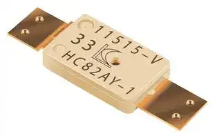
**==> picture [96 x 55] intentionally omitted <==**

**----- Start of picture text -----**<br>
1 1 5 1 5 – V<br>3 3<br>H C 8 2 AY– 1<br>&<br>**HALOGEN FREE<br>**----- End of picture text -----**<br>


## **Features**

■ High current type

- Overtemperature and overcurrent protection

- for lithium polymer and prismatic cells

- Controls abnormal, excessive current instantaneously

- ■ Wide range of temperature options

## **Applications**

Battery cell protection for: ■ Notebook PCs

- Tablet PCs

- Smart phones

■ Mobile phones

## **Komatsulite[™] HC Series Breaker** ____ZZ

## ~~**Ratings**~~

|**Specifi cation**|**Model**|**Model**|**Model**|**Model**|**Model**|
|---|---|---|---|---|---|
||**HC72AY-1**|**HC77AY-1**|**HC82AY-1**|**HC85AY-1**|**HC90AY-1**|
|Trip Temperature|72 °C ± 5 °C|77 °C ± 5 °C|82 °C ± 5 °C|85 °C ± 5 °C|90 °C ± 5 °C|
|Reset Temperature|40 °C min.|||||
|Contact Rating|DC9V / 25 A, 6000 cycles|||||
|Maximum BreakingCurrent|DC5V / 80 A, 100 cycles|||||
|Maximum Voltage|DC28V / 25 A, 100 cycles|||||
|Minimum HoldingVoltage|3 V @ 25 °C for 1 minute|||||
|Maximum Leakage Current|200 mA max. @ 25 °C|||||
|Resistance|5 milliohms max.|||||


**==> picture [499 x 284] intentionally omitted <==**

**----- Start of picture text -----**<br>
Product Dimensions Agency Recognition<br>5.8 ± 0.1 Description<br>2.7 ± 0.1 (.228 ± .004) 2.7 ± 0.1<br>(.106 ± .004) (.106 ± .004) 0.1 ± 0.01 UL, cUL File Number: E215638<br>(.004 ± .0004)<br>TUV File Number: R50203147<br>Se JS<br>1.15 How to Order<br>2.5 ± 0.1 2.5 ± 0.1 (.045) [MAX.]<br>(.098 ± .004) (.098 ± .004) HC  72  A  Y  -  1<br>(ay— (.148 ± .004)3.75 ± 0.1 [=;] DIMENSIONS: (INCHES)MM Series Designator =<br>Trip Temperature (±5 °C)<br>• 72  • 85<br>• 77  • 90<br>Product Structure • 82<br>Arm Material<br>A = Cu Alloy<br>COVER Manufacturer’s Internal Code<br>PLATE COVER - Terminal Type  —|<br>ARM<br>(with/without Projection & Terminal Length)<br>ARM CONTACT<br>TERMINAL<br> PROJECTION PTC PROJECTION<br>BASE<br>BIMETAL DISC<br>BASE<br>TERMINAL<br>**----- End of picture text -----**<br>


AVAILABLE WITH AND WITHOUT PROJECTIONS.

- RoHS Directive 2002/95/EC Jan. 27, 2003 including annex and RoHS Recast 2011/65/EU June 8, 2011.

**Bourns considers a product to be “halogen free” if (a) the Bromine (Br) content is 900 ppm or less; (b) the Chlorine (Cl) content is 900 ppm or less; and (c) the total Bromine (Br) and Chlorine (Cl) content is 1500 ppm or less.

Specifi cations are subject to change without notice.

The device characteristics and parameters in this data sheet can and do vary in different applications and actual device performance may vary over time. Users should verify actual device performance in their specifi c applications.

**==> picture [251 x 20] intentionally omitted <==**

**----- Start of picture text -----**<br>
[Komatsulite™ HC Series Breaker]<br>MF-NSMF Series - PTC Resettable Fuses<br>**----- End of picture text -----**<br>


## ~~**Typical Performance**~~

**==> picture [309 x 180] intentionally omitted <==**

**----- Start of picture text -----**<br>
Current vs. Temperature Curves<br>HC72AY-1 (Low 67 °C average)<br>21 HC77AY-1 (Low 72  ° C average)<br>2019 HC82AY-1 (Low 77  ° C average)<br>1817 HC85AY-1 (Low 80  ° C average)<br>1615 HC90AY-1 (Low 85  ° C average)<br>14<br>13<br>12<br>11<br>10<br>9<br>8<br>7<br>6<br>5<br>4<br>3<br>2<br>1<br>0<br>20                           30                          40                            50                           60                          70                           80<br>Temperature (°C)<br>Current (A)<br>**----- End of picture text -----**<br>


The above curves were derived from placing test samples in an oven at 25 ℃, 40 ℃, 60 ℃ and 70℃, increasing current fl ow through the sample at a rate of 0.1 A/minute and recording the current value when the sample trips.

## ~~**Operation**~~

**==> picture [64 x 8] intentionally omitted <==**

**----- Start of picture text -----**<br>
NORMAL CIRCUIT<br>**----- End of picture text -----**<br>


**==> picture [160 x 128] intentionally omitted <==**

**----- Start of picture text -----**<br>
CURRENT<br>EXCESSIVE<br>CURRENT<br>AND/OR<br>CIRCUIT  HEAT<br>AFTER OPENING<br>VERY LOW CURRENT<br>**----- End of picture text -----**<br>


Specifi cations are subject to change without notice. The device characteristics and parameters in this data sheet can and do vary in different applications and actual device performance may vary over time. Users should verify actual device performance in their specifi c applications.

## **[Komatsulite™ HC Series Breaker] MF-NSMF Series - PTC Resettable Fuses**

## ~~**Wiring Recommendations**~~

This is not a surface mount device for refl ow soldering. Therefore, Ni tab wiring should be accomplished by either resistance or laser welding. Solder connections should be avoided.

## ~~**Typical Part Marking**~~

**==> picture [266 x 136] intentionally omitted <==**

**----- Start of picture text -----**<br>
DATE CODE:<br>MONTH (1~9, X, Y, Z)<br>DATE<br>YEAR<br>MACHINE NO.<br>ROMAN NUMERAL (I, II, III, ETC.) = OKAYAMA FACTORY<br>12510-I ARABIC NUMERAL (1, 2, 3, ETC.) = SHIGA FACTORY<br>DIRECTION MARK ** MANUFACTURER’S TRADEMARK<br>(ALPHANUMERICCHARACTER) HC72AY-1<br>TERMINAL TYPE<br>MANUFACTURER’S INTERNAL CODE<br>ARM MATERIAL<br>(A = Cu ALLOY)<br>TRIP TEMPERATURE - °C<br>(72, 77, 82, 85, 90)<br>SERIES DESIGNATOR<br>**----- End of picture text -----**<br>


## ~~**Standard Packaging Specif cations**~~

Plastic Bag.......................................................................................................................................................................5,000 pcs. (fi xed) Inner Box .........................................................................................................................................................................5,000 pcs. (fi xed) Outer Box ....................................................................................................................................50,000 pcs. max. (up to 10 inner boxes)

**==> picture [129 x 36] intentionally omitted <==**

**Japan:** Tel: +81-6 6319 2281 • Fax: +81-6 6319 2284 **Asia-Pacifi c:** Tel: +886-2 2562-4117 • Fax: +886-2 2562-4116 **EMEA:** Tel: +36 88 520 390 • Fax: +36 88 520 211 **The Americas:** Tel: +1-951 781-5500 • Fax: +1-951 781-5700 **www.bourns.com/komatsulite**

Specifi cations are subject to change without notice. The device characteristics and parameters in this data sheet can and do vary in different applications and actual device performance may vary over time. Users should verify actual device performance in their specifi c applications.

## **[Komatsulite™ HC Series Breaker]**

## ~~**Caution when using Breaker**~~

Before using the breaker, please fully read the _DESIGN AND HANDLING CAUTIONS_ stated below so that there will be no breaker performance deterioration and/or damage to the breaker body or terminal.

## **DESIGN CAUTIONS**

1. Use within the electrical ratings specifi ed in this data sheet. If used over the rating of voltage or current, ON-OFF life might be impacted and contact may be deteriorated due to breaker arm damage.

2. If used over the electrical rating, the circuit may not open safely. Please test your device for any abnormalities and confi rm that the breaker will open the circuit safely in your device.

3. Mount the breaker on your device where heat is the highest in order to transfer it effectively to the breaker.

4. After the breaker is mounted, affi x it so that the breaker body and terminals will not move. If not affi xed, breaker resistance could increase or contact open due to stress during handling or vibration/shock during transportation.

5. Mount the breaker body and terminals in a straight and fl at direction. If the body and terminals are mounted in a twisted condition, breaker resistance could increase or create body damage.

6. If breaker is to be resin-molded, test and evaluate to determine whether the breaker can be used effectively.

7. The breaker cannot be used as a repetitive ON-OFF thermostat.

8.  The breaker is not washable. Do not wash.

9.  The breaker is not designed nor guaranteed for fl ow, refl ow or hand-soldering applications. If such application is required, test and evaluate in your specifi c application to confi rm that the breaker can be used.

10. When mounting and after mounting the breaker, do not apply supersonic vibration. Vibration and heat may cause the breaker resistance to increase or may cause body damage. If you apply supersonic vibration after mounting the breaker, test and evaluate in your specifi c application to confi rm that the breaker can be used.

11. Do not use the breaker in the following abnormal environments:

   - a) Water, oil, chemicals or organic solutions

   - b) Direct sunlight, outdoor exposure, dust

   - c) Dew condensation, allowing the breaker to get wet

   - d) Salt breeze, chlorine, hydrogen sulfi de, ammonium, sulfi de-oxidation, hydrogen chloride, and anywhere there is a possibility of generating corrosive gas such as ulfurous acid gas

   - e) Strong static electric charge or electromagnetic wave

12. Thie breaker is not designed or tested for, and should not be used in aerospace, airplane, nuclear, military, life-sustaining medical and other related equipment.

Specifi cations are subject to change without notice. The device characteristics and parameters in this data sheet can and do vary in different applications and actual device performance may vary over time. Users should verify actual device performance in their specifi c applications.

## **[Komatsulite™ HC Series Breaker]**

## ~~**Caution when using Breaker (Continued)**~~

## **HANDLING CAUTIONS**

1. Since the breaker body is composed of plastic parts, do not clamp or dent with tools as this could cause a resistance increase or body damage.

2. Breaker terminals are thin copper-alloy with right angle edges. Handle carefully to avoid injury to fi ngers. Handling while wearing fi nger cots and tweezers is recommended.

3. When welding breaker terminals or mounting the breaker on a cell or PCM board, be careful to avoid placing excessive stress on the breaker body and terminals. Excessive stress may cause a resistance increase or body damage. Please refer to the following cautions:

   - a) Do not apply more than 10 N moment to the breaker body (refer to Figure 1)

   - b) Do not apply more than 1.5 cN-m twist torque to the breaker body (refer to Figure 2)

   - c) Do not apply more than 20 N bending force to the breaker body (refer to Figure 3)

   - d) Do not apply more than 0.6 cN-m twist torque to the breaker terminals (refer to Figure 4)

   - e) Do not apply more than 2 N force to the breaker terminals (refer to Figure 5)

   - f) Do not bend terminals more than 45 ° at root (refer to Figure 6)

   - g) Do not twist terminals more than 20 ° with the breaker body affi xed.

4. In breaker body welding, normally there is direct welding (Figure 7) and series welding (Figure 8). In either case, use a suitable jig so that there will be no stress as stated above.

5. Pull-and-detach strength of the terminal welding should be to your own specifi cation. If the welding result is controlled by resistance, measurement should be made at close point to the breaker body by “4-point clip method” using a milliohm meter to ensure accuracy (refer to Figure 9).

6. Avoid putting stress as shown above in 3-a) to 3-g) when the jig is used for welding/additional processing.

**==> picture [503 x 206] intentionally omitted <==**

**----- Start of picture text -----**<br>
Figure 1 Figure 2 Figure 3 Figure 4<br>Rod A<br>Rod B<br>Figure 5 Figure 6 Figure 7 Figure 8<br>Rod A<br>45 ° 45 °<br>45 ° 45 °<br>Rod B<br>Figure 9 Due to possible updates to safety standards and other reasons, there may be changes in<br>specifi cations for this data sheet without prior notifi cation. Therefore, before design-in for<br>your application, please contact us for the most up-to-date specifi cations.<br>milliohm meter<br>**----- End of picture text -----**<br>


Specifi cations are subject to change without notice.

The device characteristics and parameters in this data sheet can and do vary in different applications and actual device performance may vary over time. Users should verify actual device performance in their specifi c applications.

06/08/15
Updated at March 31, 2026
Bourns, Inc. is a globally recognized manufacturer of high-reliability electronic components, headquartered in Riverside, California. Renowned for its engineering excellence, the company delivers critical solutions across a diverse range of demanding markets, including automotive, industrial, consumer electronics, telecommunications, and medical equipment. The Bourns product portfolio is anchored by an industry-leading selection of passive components and circuit protection devices. The brand is particularly dominant in magnetic components, offering thousands of high-performance power inductors, alongside specialized RF and toroidal inductors engineered for optimized power management and signal integrity. Equally prominent is their comprehensive suite of circuit protection solutions. This robust lineup features a vast array of standard and resettable fuses, transient voltage suppressors (including TVS varistors and diodes), and gas discharge tubes (GDTs) designed to rigorously safeguard sensitive electronics against overvoltage and overcurrent faults. Beyond its core passives and protection technologies, Bourns manufactures highly effective EMC and RFI suppression components, such as common mode chokes and power line filters. The company's offering also extends into discrete semiconductors and power management, including Schottky diodes, fast recovery rectifiers, bridge rectifiers, and board-level transformers. This expansive breadth of quality components provides design engineers with a trusted foundation for developing resilient, efficient, and long-lasting electronic systems.
About Novapart
Novapart is a B2B electronic component broker specialising in stock shortages and cost reduction. We source hard-to-find parts and identify compliant alternatives across a catalogue of 410,000+ components from 500+ manufacturers.
Learn more →Stock Shortage Specialist
When a component is unavailable, discontinued or has an unacceptable lead time, we tap into our network of vetted European and Asian distributors to source what you need — without compromising on quality or traceability.
Request a quote →Compliant Alternatives
We identify pin-to-pin, electrically equivalent substitutes that meet the same certifications (RoHS, AEC-Q100, REACH) as your original specification — validated against datasheets, not just part numbers. Often at a lower cost.
BOM Analysis service →