
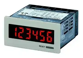


H7HP-C8D
Total Counter, 8-Digit, 12 mm, 12 VDC to 24 VDC
- Manufacturer: OMRON INDUSTRIAL AUTOMATION
- Product type:
- SVHC: To Be Advised
- Digit Height: 12mm
- Product Range: H7HP Series
- Panel Cutout Width: 68mm
- Supply Voltage Max: 24VDC
- Supply Voltage Min: 12VDC
- Panel Cutout Height: 33mm
- No. of Digits / Alpha: 8
- Operating Temperature Max: 55°C
- Operating Temperature Min: -10°C
| Delivery and price | |
|---|---|
| Units per pack | 1 |
| Price | 206.3 € |
| Current stock | 10+ |
| Lead time | 30 days |
**Total Counter/Time Counter (DIN 72 x 36) H7HP**

CSM_H7HP_DS_E_5_3

## **DIN 72 x 36-mm Total Counter/Time Counter with Easy-to-read Displays and Water and Oil Resistance Equivalent to IP66**

- Large, easy-to-read displays: 15-mm-high characters for 6-digit models; 12-mm-high characters for 8-digit models.

- High-visibility, negative transmissive LCD display with built-in red LED backlight at low power consumption.

- IP66 with oil resistance and NEMA4 are achieved by unifying the front with the casing case and using oil-resistant materials and parts.

- Compact (66 mm) body.

- Switch 6-digit models between total counter and time counter operation.

- Just change a switch setting for either an NPN or PNP input.

For the most recent information on models that have been certified for safety standards, refer to your OMRON website.

- Supports both external resetting and manual resetting.

- Finger-protection terminal block cover prevents electrical shock and conforms to VDE0106, Part 100.

- Safety standards: UL, CSA, EMC (EN 61326), CE Marking.

## **Model Number Structure**

## ■ **Model Number Legend**

## **H7HP-** @@@@

**1   2  3  4**

## **1. Classification**

- A: Total counter/time counter

C: Total counter

**2. Digits** None: 6 digits

- 8: 8 digits

## **3. Supply Voltage**

None: 100 to 240 VAC

   - D: 12 to 24 VDC

**4. Case Color**

None: Light gray (Munsell 5Y7/1)

B: Black

## **Orderin Information g**

## ■ **List of Models**

|**Supply voltage**|**6-digit total counter/time counter**|**6-digit total counter/time counter**|**8-digit total counter**|**8-digit total counter**|
|---|---|---|---|---|
||**Lightgray**|**Black**|**Lightgray**|**Black**|
|100 to 240 VAC|H7HP-A|H7HP-AB|H7HP-C8|H7HP-C8B|
|12 to 24 VDC|H7HP-AD|H7HP-ADB|H7HP-C8D|H7HP-C8DB|


**1**

**H7HP**

## **S ecifications p**

## ■ **Ratings**

|■**Ratings**|■**Ratings**|||||
|---|---|---|---|---|---|
|**Item**||**6-digit total counter/time counter**||**8-digit total counter**||
|||**H7HP-A**|**H7HP-AD**|**H7HP-C8**|**H7HP-C8D**|
|**Rated supply voltage**||100 to 240 VAC (50/60 Hz)|12 to 24 VDC (see note 1)|100 to 240 VAC (50/60 Hz)|12 to 24 VDC (see note 1)|
|**External power supply**||50 mA at 12 VDC|---|50 mA at 12 VDC|---|
|**Operating voltage range**||85% to 110% of rated supply voltage||||
|**Power consumption**||100 to 240 VAC: 6.5 VA max.<br>12 to 24 VDC:<br>0.6 W max.||||
|**Dimensions**||72 x 36 x 66 mm (W x H x D)||||
|**Mounting method**||Flush mounting||||
|**External connections**||Screw terminals||||
|**Degree of protection**||Panel surface: IP66 with oil resistance, NEMA 4 (indoors). Panel surface only: IEC IP66. IEC IP66||||
|**Display**||7-segment, negative transmissive LCD (with red backlight)||||
|**Digits**||6 digits (15-mm-high characters)||8 digits (12-mm-high characters)||
|**Function**||Total counter/time counter (selected via DIP switch)||Total counter||
|**Input mode**||Up/down (individual) (total counter), or accumulative<br>(time counter)||Up/down (individual)||
|**Max. counting speeds**||30 Hz or 5 kHz (selected via DIP switch)||||
|**Counting range**||–99999 to 999999||–9999999 to 99999999||
|**Time specification**||0.1 to 99999.9 h/1 s to 99 h 59 min 59 s<br>(selected via DIP switch)||---||
|**Timing accuracy**||±100ppm(–10°C to 55°C)||---||
|**Memory backup**||EEP-ROM(overwrites: 200,000 times min.)that can store data for 20years min.||||
|**Input**|**Input signals**|Count 1/start, count 2/gate, reset, and key protection(see note 2)||||
||**Input method**|No-voltage input(NPN transistor input)or voltage input(PNP transistor input) (selected via DIP switch)||||
||**Count, start,**<br>**gate, reset**|No-voltage input (NPN transistor input)<br>Short-circuit (ON) impedance:<br>1 kΩmax.<br>Short-circuit (ON) residual voltage: 2 VDC max.<br>Open (OFF) impedance:<br>100 kΩmin.<br>Voltage input (PNP transistor input)<br>Short-circuit (ON) impedance:<br>1 kΩmax.<br>ON voltage:<br>9 to 24 VDC<br>OFF voltage:<br>5 VDC max.<br>Open(OFF)impedance:<br>100 kΩmin.||||
||**Key protection**|No-voltage input (NPN transistor input)<br>Short-circuit (ON) impedance:<br>1 kΩmax.<br>Short-circuit (ON) residual voltage: 0.5 VDC max.<br>Open(OFF)impedance:<br>100 kΩmin.||||
|**Input re-**<br>**sponse**<br>**speed**|**Reset**|Time counter: 20 ms; total counter: 20 ms or 1 ms(automaticallyswitched accordingto countingspeed)||||
||**Start**|Time counter: 20 ms||||
||**Key protection**|Approx. 1 s||Approx. 1 s||
|**Reset system**||External and manual resets||||


- **Note: 1.** Contains 20% ripple (p-p) max.

**2.** Only a non-voltage input (NPN transistor) is possible for the key protection input. The key protection input will be a non-voltage input even if the NPN/PNP input mode is set to PNP. Key protection is used to prohibit operating the Reset Key. The reset input terminals will still be functional.

**==> picture [539 x 34] intentionally omitted <==**

**2**

**H7HP**

## ■ **Characteristics**

|**Insulation resistance**|100 MΩmin. (at 500 VDC)|
|---|---|
|**Dielectric strength**|2,000 VAC, 50/60 Hz for 1 min between current-carrying terminal and exposed non-current-carrying metal parts<br>(AC model)<br>1,000 VAC, 50/60 Hz for 1 min between current-carrying terminal and exposed non-current-carrying metal parts<br>(DC model)<br>2,000 VAC, 50/60 Hz for 1 min between power terminals and control input terminals (AC model)|
|**Impulse withstand voltage**|3 kV (between power terminals) (1 kV for 12-to-24-VDC models)<br>4.5 kV (between current-carrying terminal and exposed non-current-carrying metal parts) (1.5 kV for 12-to-24-VDC<br>models)|
|**Noise immunity**|±1.5 kV (between AC power terminals),±480 V (between DC power terminals),<br>±480 V (between input terminals);<br>square-wave noise bynoise simulator(pulse width: 100 ns/1μs, 1-ns rise)|
|**Static immunity**|Display:<br>Malfunction: 8 kV<br>Destruction: 15 kV<br>DIP switch: Malfunction: 4 kV<br>Destruction: 8 kV|
|**Vibration resistance**|Destruction: 10 to 55 Hz with 0.75-mm single amplitude, 2 hours each in three directions<br>Malfunction: 10 to 55 Hz with 0.5-mm single amplitude, 10 minutes each in three directions|
|**Shock resistance**|Destruction: 294 m/s2each in three directions<br>Malfunction: 196 m/s2each in three directions|
|**Ambient temperature**|Operating: –10°C to 55°C (with no icing)<br>Storage:<br>–25°C to 65°C (with no icing)|
|**Ambient humidity**|Operating: 35% to 85%|
|**EMC**|(EMI)<br>EN61326-1 (note 1.)<br>Emission Enclosure:<br>EN55011 Group 1 class A<br>Emission AC Mains:<br>EN55011 Group 1 class A<br>(EMS)<br>EN61326-1 (note 1.)<br>Immunity ESD:<br>EN61000-4-2:<br>4 kV contact discharge (level 2)<br>8 kV air discharge (level 3)<br>Immunity RF-interference:<br>EN61000-4-3:<br>10 V/m (Amplitude-modulated, 80 MHz to 1 GHz) (level 3);<br>10 V/m (Pulse-modulated, 900 MHz±5 MHz) (level 3)<br>Immunity Conducted Disturbance:<br>EN61000-4-6:<br>10 V (0.15 to 80 MHz) (according to EN61000-6-2)<br>Immunity Burst:<br>EN61000-4-4:<br>2 kV power-line (level 3);<br>2 kV I/O signal-line (level 4)<br>Immunity Surge:<br>EN61000-4-5:<br>1 kV line to lines (power and output lines) (level 2);<br>2 kV line to ground (power and output lines) (level 3)<br>ImmunityVoltage Dip/Interruption:<br>EN61000-4-11: 0.5 cycle, 100%(rated voltage)|
|**Approved standards**|UL508(note 2), CSA C22.2 No.14(note 2), conforms to EN61010-1, VDE0106/P100|
|**Case color**|Rear section: Graysmoke; Front section: 5Y7/1(lightgray)or N1.5(black)|
|**Weight**|Approx. 115g|


- **Note: 1.** Industrial electromagnetic environment (EN/IEC 61326-1 Table 2)

   **2.** UL508 and CAN/CSA-C22.2 No.14 certification conditions

      - Power supply 100 to 240VAC types Ambient temperature 30 ° C Single mounting

      - Power supply 12 to 24VDC types Ambient temperature 40 ° C Single mounting

**==> picture [539 x 34] intentionally omitted <==**

**3**

**H7HP**

## **Connections**

## ■ **Terminal Arrangement**

**Note: 1.** Incremented for count 1 (CP1) inputs; decremented for count 2 (CP2) inputs. **2.** Non-contact input is also available.

## **AC Models**

## **H7HP-A**

**==> picture [460 x 343] intentionally omitted <==**

**----- Start of picture text -----**<br>
H7HP-C8<br>100 to 240 VAC External power supply  100 to 240 VAC External power supply<br>12 VDC 50 mA max. 12 VDC 50 mA max.<br>Power supply Power supply Unused Unused Unused 0 V 12 VDC Power supply Power supply Unused Unused Unused 0 V 12 VDC<br>5 6 7 8 9 10 11 5 6 7 8 9 10 11<br>1 2 3 4 1 2 3 4<br>Key protectioninput Reset input Count 1 input or start input Count 2 input or gate input Key protection input Reset input Count 1 input Count 2 input<br>b re |<br>NPN mode NPN mode<br>PNP mode<br>PNP mode<br>DC Models<br>H7HP-AD<br>H7HP-C8D<br>12 to 24 VDC 12 to 24 VDC<br>0 V Power supply Unused Unused Unused Unused Unused 0 V Power supply Unused Unused Unused Unused Unused<br>5 6 7 8 9 10 11 5 6 7 8 9 10 11<br>1 2 3 4 1 2 3 4<br>Key  Count 1  Count 2  Key  Reset  Count 1  Count 2<br>protectioninput Reset input input or start input input or gate input protectioninput input input input<br>NPN mode<br>NPN mode PNP mode<br>PNP mode<br>**----- End of picture text -----**<br>


## **DC Models**

**==> picture [41 x 7] intentionally omitted <==**

**----- Start of picture text -----**<br>
H7HP-AD<br>**----- End of picture text -----**<br>


## **O eration p**

## ■ **DIP Switch Settings**

Switches 1 to 4 are all set to OFF before shipping.

## **H7HP-A** @

|**Pin no.**|**Item**|**OFF**|**ON**|
|---|---|---|---|
|1<br>Function|Function|Total counter|Time counter|
|2<br>Counting speed<br>(note)<br>Time ran|Counting speed<br>(note)|30 Hz|5 kHz|
||Time range (note)|99999.9 h|99 h 59 min 59 s|
|3<br>Input mode (note)|Input mode (note)|NPN|PNP|
|4<br>Unused|Unused|---|---|


## **H7HP-C** @

|**Pin no.**|**Item**|**OFF**|**ON**|
|---|---|---|---|
|1|Unused|---|---|
|2|Counting speed<br>(note)|30 Hz|5 kHz|
|3|Input mode (note)|NPN|PNP|
|4|Input mode (note)<br>Unused|---|---|


**Note:** When the setting has been changed, turned power off and on to continue. The display will show “0” when the power is turned back on.

**4** omrRONn ~~a~~

**H7HP**

## ■ **Operating Modes**

## **Total Counters**

**==> picture [45 x 110] intentionally omitted <==**

**----- Start of picture text -----**<br>
Reset input<br>CP1<br>CP2<br>999999<br>(see note)<br>Display  0<br>**----- End of picture text -----**<br>


−99999 (see note) display **Note:** Display values are shown for a 6-digit model. The count value will return to "0" when "999999" is exceeded. The display and output are turned OFF when the power supply turns OFF, but the count value is stored internally.

## **Time Counters**

**==> picture [56 x 114] intentionally omitted <==**

**----- Start of picture text -----**<br>
Reset input<br>Gate input<br>Start input<br>99999.9h *<br>Display<br>0.0 h<br>**----- End of picture text -----**<br>


- Display values are shown for full scale set to 99999.9 h.

**Note:** The count value will return to "0" when "99999.9" is exceeded. The display and output are turned OFF when the power supply turns OFF, but the count value is stored internally.

## **Nomenclature**

**==> picture [5 x 7] intentionally omitted <==**

**----- Start of picture text -----**<br>
2<br>**----- End of picture text -----**<br>


(The figure shows the DIP switch label stuck to the rear of the case.)

## 1

**==> picture [5 x 6] intentionally omitted <==**

**----- Start of picture text -----**<br>
3<br>**----- End of picture text -----**<br>


1. **Reset Key**

Resets the count value, but will not operate while the keys are protected.

2. **Key Protection Indicator**

Lit while the keys are protected (Reset Key is disabled.).

3. **DIP Switch**

Use to change a setting. Refer to _DIP Switch Settings_ for details.

**5**

**H7HP**

## **Dimensions**

**Note:** All units are in millimeters unless otherwise indicated.

**H7HP-A H7HP-C8** r 677 M3.5 terminal screw ealeall JUL Jkalegtt oe oO | oO Terminal cover (provided) | —— 36 7 = — 7 as sgl ie 65.8 _ **Panel Cutouts** Panel cutouts are as shown below (according to DIN43700). ) **Note: 1.** The mounting panel thickness should be 1 to 6 mm. 3377" **2.** Water resistance will be lost if Counters are mounted side-by-side.

**With Flush Mounting Bracket**

Y92S-33 rubber Panel Y92F-33 flush mounting packing (provided) adaptor (provided)

**6**

**H7HP**

**Connections (Common)**

## ■ **Input Connections**

**Note:** The following is common for all H7GP/H7HP models.

## **No-voltage Input (NPN Input Mode)**

## **Reset, Count 1, Count 2, Start, and Gate Inputs**

**==> picture [195 x 107] intentionally omitted <==**

**----- Start of picture text -----**<br>
Open Collector Output  Voltage Output<br>H7GP/H7HP  H7GP/H7HP<br>12 VDC C) 12 VDC<br>Sensor  Sensor<br>7 Reset input  R, Reset input<br>Count 1 input  Count 1 input<br>| a<br>Count 2 input  Count 2 input<br>Start input  Start input<br>Gate input  Gate input<br>0 V  a5C) 0 V<br>**----- End of picture text -----**<br>


12 VDC (12 to 24 VDC)

## **Reset, Count 1, Count 2, Start, and Gate Inputs Specification**

Short-circuit (ON) impedance: 1 kΩ max. Short-circuit (ON) residual voltage: 2 VDC max. Current flow for 0-Ω short-circuit: Approx. 2 mA Open (OFF) impedance: 100 kΩ min. **Note:** Two-wired sensors cannot be used.

## **Key Protection Input**

**==> picture [189 x 106] intentionally omitted <==**

**----- Start of picture text -----**<br>
Open Collector Output  Voltage Output<br>H7GP/H7HP  H7GP/H7HP<br>12 VDC C) 12 VDC<br>Sensor  Sensor<br>' Ry<br>Key  Key<br>| protection  aa protection<br>input  input<br>0 V  a3© 0 V<br>**----- End of picture text -----**<br>


## **Key Protection Inputs Specification**

Short-circuit (ON) impedance: 1 kΩ max. Short-circuit (ON) residual voltage: 0.5 VDC max. Current flow for 0-Ω short-circuit: Approx. 0.5 mA Open (OFF) impedance: 100 kΩ min. **Note:** Two-wired sensors cannot be used.

## **Voltage Input (PNP Input Mode)**

## **Reset, Count 1, Count 2, Start, and Gate Inputs**

**==> picture [86 x 77] intentionally omitted <==**

**----- Start of picture text -----**<br>
12 VDC<br>Sensor<br>Reset input<br>Count 1 input<br>|,C) Count 2 input Start input<br>e 3 Gate input<br>O 0 V<br>**----- End of picture text -----**<br>


## **Reset, Count 1, Count 2, Start, and Gate Inputs Specification**

Short-circuit (ON) impedance: 1 kΩ max. ON voltage: 9 to 24 VDC OFF voltage: 5 VDC max. Open (OFF) impedance: 100 kΩ min. Input impedance: Approx. 3.8 kΩ **Note:** Two-wired sensors cannot be used.

**7** omRon ~~a~~

**H7HP**

## **Safety Precautions (Common)**

Refer to _Safety Precautions for All Counters_ .

**Note:** The following is common for all H7GP/H7HP models.

## ! **CAUTION**

This may occasionally cause electric shock, fire, or malfunction. Never disassemble, repair, or modify the H7GP/H7HP.

This may occasionally cause electric shock, fire, or malfunction. Do not allow metal fragments or lead wire scraps to fall inside the H7GP/H7HP.

## ■ **Precautions for Safe Use**

Observe the following items to ensure the safe use of this product.

## **Environmental Precautions**

- Store the H7GP/H7HP within the specified ratings. If the H7GP/ H7HP has been stored at temperatures −10°C or lower, let it stand for 3 hours or longer at room temperature before turning ON the power supply.

- Use the H7GP/H7HP within the specified ratings for operating temperature and humidity.

- Do not operate the H7GP/H7HP in locations subject to sudden or extreme changes in temperature, or locations where high humidity may result in condensation.

- Do not use the H7GP/H7HP in locations subject to vibrations or shock. Extended use in such locations may result in damage due to stress.

- Do not use the H7GP/H7HP in locations subject to excessive dust, corrosive gas, or direct sunlight.

- Install the H7GP/H7HP well away from any sources of static electricity, such as pipes transporting molding materials, powders, or liquids.

- The H7GP/H7HP is not waterproof or oil resistant. Do not use it in locations subject to water or oil.

- The life expectancy of internal components may be reduced if the H7GP/H7HP is mounted side-by-side.

- Do not use organic solvents (such as paint thinner or benzine), strong alkaline, or strong acids because they will damage the external finish.

## **Usage Precautions**

- Although the H7GP/H7HP power supply (primary side) is isolated from control circuits (secondary side) by a transformer, the primary and secondary sides of the transformer are linked by a capacitor, making it possible for high-frequency components to leak to the secondary side. Take adequate precautions against electrical shock. Do not connect input circuits to exposed parts (such as the machine body) and be sure that the power supply is turned off before wiring.

**==> picture [70 x 52] intentionally omitted <==**

**----- Start of picture text -----**<br>
Control  Display<br>circuit circuit<br>Input<br>circuit<br>T<br>**----- End of picture text -----**<br>


## **Flush Mounting**

The panel surface is water-resistive (conforming to NEMA 4 and IP66). In order to prevent the internal circuit from water penetration through the space between the counter and operating panel, attach a rubber packing between the counter and operating panel and secure the rubber packing with the Y92F-3@ flush-mounting adaptor.

Be sure the rubber packing is installed in the correct direction. The wider portion must be facing the panel when installed, as shown in the following illustration. Using a flat-head screwdriver, press in the Mounting Adapter until it cannot be pressed in any further in order to ensure water-resistive performance.

**==> picture [87 x 73] intentionally omitted <==**

**----- Start of picture text -----**<br>
Wider portion  Adapter<br>facing panel<br>Panel<br>**----- End of picture text -----**<br>


## **Other**

Oil resistance is not applicable to all types of oil. Be sure to test any specific oils before actual application.

- Install a switch or circuit breaker that allows the operator to immediately turn OFF the power, and label it to clearly indicate its function.

- Be sure to wire the terminals correctly.

- Do not install input lines in the same duct or conduit as power supply or other high-voltage lines. Doing so may result in malfunction due to noise. Separate the input lines from highvoltage lines.

- Internal elements may be destroyed if a voltage outside the rated voltage is applied.

- Maintain voltage fluctuations in the power supply within the specified range.

- Use a switch, relay, or other contact so that the rated power supply voltage will be reached within 0.1 s. If the power supply voltage is not reached quickly enough, the H7GP/H7HP may malfunction or outputs may be unstable.

**8**

**H7HP**

## ■ **Precaution for Correct Use**

## **Power Supplies**

When turning the power ON and OFF, input signal reception is possible, unstable, or impossible as shown in the diagram below. Apply the power supply voltage through a relay or switch in such a way that the voltage reaches a fixed value immediately.

Power ON supply OFF 200 ms 0 to 90 ms 0 to 2 s 5 ms Input Impossible Possible Unstable Impossible Unstable

## **- Self diagnostic Function**

The following displays will appear if an error occurs.

|**Display**|**Error**|**Correction**|
|---|---|---|
|----|Less than –99999<br>(H7HP, 6-digit model)<br>Less than –99999999<br>(H7HP, 8-digit model)|Press RST Key or reset<br>input|
|e1|CPU|Press RST Key or turn<br>power OFF and then ON|
|e2|Memory||


## **Labels**

Unit labels are included with the H7GP/H7HP and DIP switch labels are included with the H7HP. Attach these labels as shown in the following illustrations.

## **Unit Labels**

**==> picture [25 x 60] intentionally omitted <==**

**----- Start of picture text -----**<br>
H7GP<br>H7HP<br>**----- End of picture text -----**<br>


## **DIP Switch Labels**

**H7HP**

ALL DIMENSIONS SHOWN ARE IN MILLIMETERS.

In the interest of product improvement, specifications are subject to change without notice.

To convert millimeters into inches, multiply by 0.03937. To convert grams into ounces, multiply by 0.03527.

**9** omRon ~~a~~

## Terms and Conditions Agreement

## Read and understand this catalog.

Please read and understand this catalog before purchasing the products.  Please consult your OMRON representative if you have any questions or comments.

## Warranties.

(a) Exclusive Warranty. Omron’s exclusive warranty is that the Products will be free from defects in materials and workmanship for a period of twelve months from the date of sale by Omron (or such other period expressed in writing by Omron). Omron disclaims all other warranties, express or implied.

(b) Limitations. OMRON MAKES NO WARRANTY OR REPRESENTATION, EXPRESS OR IMPLIED, ABOUT NON-INFRINGEMENT, MERCHANTABILITY OR FITNESS FOR A PARTICULAR PURPOSE OF THE PRODUCTS. BUYER ACKNOWLEDGES THAT IT ALONE HAS DETERMINED THAT THE

PRODUCTS WILL SUITABLY MEET THE REQUIREMENTS OF THEIR INTENDED USE.

Omron further disclaims all warranties and responsibility of any type for claims or expenses based on infringement by the Products or otherwise of any intellectual property right. (c) Buyer Remedy. Omron’s sole obligation hereunder shall be, at Omron’s election, to (i) replace (in the form originally shipped with Buyer responsible for labor charges for removal or replacement thereof) the non-complying Product, (ii) repair the non-complying Product, or (iii) repay or credit Buyer an amount equal to the purchase price of the non-complying Product; provided that in no event shall Omron be responsible for warranty, repair, indemnity or any other claims or expenses regarding the Products unless Omron’s analysis confirms that the Products were properly handled, stored, installed and maintained and not subject to contamination, abuse, misuse or inappropriate modification. Return of any Products by Buyer must be approved in writing by Omron before shipment. Omron Companies shall not be liable for the suitability or unsuitability or the results from the use of Products in combination with any electrical or electronic components, circuits, system assemblies or any other materials or substances or environments. Any advice, recommendations or information given orally or in writing, are not to be construed as an amendment or addition to the above warranty.

See http://www.omron.com/global/ or contact your Omron representative for published information.

## Limitation on Liability; Etc.

OMRON COMPANIES SHALL NOT BE LIABLE FOR SPECIAL, INDIRECT, INCIDENTAL, OR CONSEQUENTIAL DAMAGES, LOSS OF PROFITS OR PRODUCTION OR COMMERCIAL LOSS IN ANY WAY CONNECTED WITH THE PRODUCTS, WHETHER SUCH CLAIM IS BASED IN CONTRACT, WARRANTY, NEGLIGENCE OR STRICT LIABILITY. Further, in no event shall liability of Omron Companies exceed the individual price of the Product on which liability is asserted.

## Suitability of Use.

Omron Companies shall not be responsible for conformity with any standards, codes or regulations which apply to the combination of the Product in the Buyer’s application or use of the Product. At Buyer’s request, Omron will provide applicable third party certification documents identifying ratings and limitations of use which apply to the Product. This information by itself is not sufficient for a complete determination of the suitability of the Product in combination with the end product, machine, system, or other application or use. Buyer shall be solely responsible for determining appropriateness of the particular Product with respect to Buyer’s application, product or system. Buyer shall take application responsibility in all cases.

NEVER USE THE PRODUCT FOR AN APPLICATION INVOLVING SERIOUS RISK TO LIFE OR PROPERTY OR IN LARGE QUANTITIES WITHOUT ENSURING THAT THE SYSTEM AS A WHOLE HAS BEEN DESIGNED TO ADDRESS THE RISKS, AND THAT THE OMRON PRODUCT(S) IS PROPERLY RATED AND INSTALLED FOR THE INTENDED USE WITHIN THE OVERALL EQUIPMENT OR SYSTEM.

## Programmable Products.

Omron Companies shall not be responsible for the user’s programming of a programmable Product, or any consequence thereof.

## Performance Data.

Data presented in Omron Company websites, catalogs and other materials is provided as a guide for the user in determining suitability and does not constitute a warranty. It may represent the result of Omron’s test conditions, and the user must correlate it to actual application requirements. Actual performance is subject to the Omron’s Warranty and Limitations of Liability.

## Change in Specifications.

Product specifications and accessories may be changed at any time based on improvements and other reasons. It is our practice to change part numbers when published ratings or features are changed, or when significant construction changes are made. However, some specifications of the Product may be changed without any notice. When in doubt, special part numbers may be assigned to fix or establish key specifications for your application. Please consult with your Omron’s representative at any time to confirm actual specifications of purchased Product.

## Errors and Omissions.

Information presented by Omron Companies has been checked and is believed to be accurate; however, no responsibility is assumed for clerical, typographical or proofreading errors or omissions.

**In the interest of product improvement, specifications are subject to change without notice.**

## **OMRON Corporation**

## **Industrial Automation Company**

2016.7

**http://www.ia.omron.com/**

(c)Copyright OMRON Corporation 2016 All Right Reserved.
Updated at April 29, 2026
With a legacy spanning over 80 years, Omron Industrial Automation is a globally recognized leader in the manufacture of advanced industrial control and automation components. Renowned for their reliability and engineering excellence, Omron delivers comprehensive solutions that enhance efficiency, machine safety, and precision across a wide range of manufacturing environments. Our extensive portfolio of Omron products is heavily focused on their industry-leading sensing and switching technologies. We offer a vast selection of sensors, excelling specifically in high-performance proximity sensors, light sensors, and temperature sensors. Complementing this range are robust switching solutions, featuring a deep inventory of power relays, solid-state relays, safety relays, and essential relay accessories designed for demanding operational requirements. Beyond sensing and switching, Omron is highly regarded for its precision automation and process control equipment. Our selection features highly accurate temperature controllers, versatile process controllers, and sophisticated panel displays and instrumentation. To support these fundamental systems, we also supply dependable Omron power supplies, notably AC/DC converters, alongside vital connectivity components like DIN rail terminal blocks to ensure secure, efficient, and complete industrial setups.
About Novapart
Novapart is a B2B electronic component broker specialising in stock shortages and cost reduction. We source hard-to-find parts and identify compliant alternatives across a catalogue of 410,000+ components from 500+ manufacturers.
Learn more →Stock Shortage Specialist
When a component is unavailable, discontinued or has an unacceptable lead time, we tap into our network of vetted European and Asian distributors to source what you need — without compromising on quality or traceability.
Request a quote →Compliant Alternatives
We identify pin-to-pin, electrically equivalent substitutes that meet the same certifications (RoHS, AEC-Q100, REACH) as your original specification — validated against datasheets, not just part numbers. Often at a lower cost.
BOM Analysis service →