
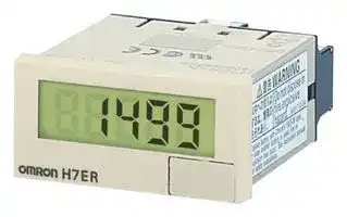


H7ER-N
Tachometer, 4-Digit, 8.6 mm, 7-Segment LCD
- Manufacturer: OMRON INDUSTRIAL AUTOMATION
- Product type:
- SVHC: To Be Advised
- Digit Height: 8.6mm
- Product Range: H7ER Series
- Panel Cutout Width: 45mm
- Supply Voltage Max: -
- Supply Voltage Min: -
- Panel Cutout Height: 22.2mm
- No. of Digits / Alpha: 4
- Operating Temperature Max: 55°C
- Operating Temperature Min: -10°C
| Delivery and price | |
|---|---|
| Units per pack | 1 |
| Price | 84.75 € |
| Current stock | 10+ |
| Lead time | 30 days |
**Self-powered Totalizer New H7E**

CSM_H7E_-N_DS_E_9_3

## **Compact Economical Totalizer with High Visibility Available with Backlit LCD Display**

- Large display with 8.6-mm character height.

- Includes new models with backlight for improved visibility in dimly lit places. (Requires 24-VDC power supply.)

- Black and light-gray cases now available.

- PNP/NPN universal DC voltage input types now available.

- Battery is replaceable for Totalizer reuse and conservation of the environment.

- Key-protect switch to prevent faulty reset key operation.

- Dual operation mode.

- Front face compatible with NEMA4/IP66.

- Short body, all models have a depth of 48.5 mm.

- Finger protection terminal block conforms to VDE0106, Part100.

- Conforms to UL, CSA, and CE marking.

- Conforms to EN61010-1 (pollution degree 2/overvoltage category III .)

- Conforms to EMC standards and EN61326, thus allowing use in residential, commercial and light- and heavy-industry environments.

- Six-language instruction manual provided.

- PCB-mounting models available. (Requires 3-V power supply.)

## ■ **Broad Line-up of the New H7E Series**

## **New H7E**

**==> picture [482 x 203] intentionally omitted <==**

**----- Start of picture text -----**<br>
New H7EC New H7ET New H7ER New H7E @ -N @ P<br>Total Counter Time Counter Tachometer PCB-mounting Counter<br>•   8-digit •   999999.9h/  •   1,000 s [-1]  with  •   Total Counter (8-digit)<br>3999d23.9h •   Time Counter (999999.9h)<br>     1 pulse/rev. encoder<br>•   999h59min59s/  •   1,000.0 s [-1]  with<br>9999h59.9min      10 pulse/rev. encoder<br>•   1,000 min [-1]  with<br>     60 pulse/rev. encoder<br>•   10,000 min [-1]  with<br>     60 pulse/rev. encoder<br>•   1,000.0 min [-1]  with<br>     600 pulse/rev. encoder<br>**----- End of picture text -----**<br>


## **Contents**

## **Self-powered Totalizers**

|**Contents**<br>**Self-powered Totalizers**<br>600 pulse/rev. encoder||
|---|---|
|H7EC.....................................................................................................................|2|
|H7ET .....................................................................................................................|9|
|H7ER.....................................................................................................................|16|
|H7E@-N@P ...........................................................................................................|22|
|**Common to All Totalizers**||
|Accessories...........................................................................................................|27|
|Precautions ...........................................................................................................|29|


**1** ~~a~~

**Self-powered Total Counter New H7EC**

- Eight-digits, counting range 0 to 99999999.

- Dual input speed: 30 Hz ←→ 1 kHz (except for AC/DC multivoltage input models)

For the most recent information on models that have been certified for safety standards, refer to your OMRON website.

## **Model Number Structure**

## ■ **Model Number Legend**

**Note:** Some configurations are not available.

> **H7EC - N      -** oOo **1 2 3**

## **1. Count Input**

None:   No-voltage input V: PNP/NPN universal DC voltage input FV: AC/DC multi-voltage input **2. Case Color** None: Light gray B: Black

## **3. Display**

None: 7-segment LCD without backlight H: 7-segment LCD with backlight

**Note:** Estimates can be provided for coatings and other specifications that are not given in the datasheet. Ask your OMRON representative for details.

## **Orderin Information g**

## ■ **Total Counters**

|**Count input**|**Max. counting speed**|**Display**|**Model**|**Model**|
|---|---|---|---|---|
||||**Light-gray body**|**Black body**|
|PNP/NPN universal DC<br>voltage input<br>(4.5 to 30 VDC)|30 Hz←→1 kHz<br>(switchable)|7-segment LCD with<br>backlight|H7EC-NV-H|H7EC-NV-BH|
|||7-segment LCD|H7EC-NV|H7EC-NV-B|
|AC/DC multi-voltage input<br>(24 to 240 VAC/VDC)|20 Hz|7-segment LCD|H7EC-NFV|H7EC-NFV-B|
|No-voltage|30 Hz←→1 kHz<br>(switchable)|7-segment LCD|H7EC-N|H7EC-N-B|


## ■ **Accessories (Order Separately)**

|**Name**|**Model**|
|---|---|
|**Compact Flush Mounting Bracket**|Y92F-35|
|**Flush Mounting Bracket (See note 1)**|Y92F-34|
|**Wire-wrap Terminal (set of two Terminals)**|Y92S-37|
|**Lithium Battery (See note 2)**|Y92S-36|
|**Waterproof Packing (See note 1)**|Y92S-32|


**Note: 1.** Provided with H7EC. (Order additional Brackets separately as required.)

**2.** Built into H7EC. Order replacements using the above model number before the service life expires.

**2** ~~—~~

**New H7EC**

## **S ecifications p**

## ■ **General**

|■**General**||||
|---|---|---|---|
|**Item**|**H7EC-NV-**@<br>**H7EC-NV-**@**H**|**H7EC-NFV-**@|**H7EC-N-**@|
|**Operating mode**|Uptype|||
|**Mounting method**|Flush mounting|||
|**External connections**|Screw terminals, optional Wire-wrapTerminals(see note 1)|||
|**Reset**|External/Manual reset|||
|**Number of digits**|8|||
|**Count input**|PNP/NPN universal DC voltage in-<br>put|AC/DC multi-voltage input|No-voltage input|
|**Display**|7-segment LCD with or without backlight, zero suppression(character height: 8.6 mm) (see note 2)|||
|**Max. counting speed**|30 Hz/1 kHz|20 Hz|30 Hz/1 kHz|
|**Case color**|Lightgrayor black(-B models)|||
|**Attachment**|Waterproofpacking, Y92F-34 Flush MountingBracket|||
|**Approved standard**|UL863, CSA C22.2 No.14, Lloyds<br>Conforms to EN61010-1/IEC61010-1 (Pollution degree2/overvoltage categoryIII)<br>Conforms to VDE0106/P100|||


**Note: 1.** Separately ordered Wire-wrap Terminals (Y92S-37) are required.

**2.** Only PNP/NPN universal DC voltage input models (-H models) have a backlight.

## ■ **Ratings**

|■**Ratings**||||
|---|---|---|---|
|**Item**|**H7EC-NV-**@<br>**H7EC-NV-**@**H**|**H7EC-NFV-**@|**H7EC-N-**@|
|**Supply voltage**|Backlight model: 24 VDC (0.3 W max.)<br>(only for backlight)<br>No-backlight model: Not required<br>(powered bybuilt-in battery)|Not required (powered by built-in battery)||
|**Count input**|High (logic) level: 4.5 to 30 VDC<br>Low (logic) level: 0 to 2 VDC<br>(Input impedance: Approx. 4.7 kΩ)|High (logic) level: 24 to 240 VAC/VDC,<br>50/60 Hz<br>Low (logic) level: 0 to 2.4 VAC/VDC, 50/<br>60 Hz|No voltage input<br>Maximum short-circuit impedance:<br>10 kΩmax.<br>Short-circuit residual voltage: 0.5 V max.<br>Minimum open impedance: 750 kΩmin.|
|**Reset input**||No voltage input<br>Maximum short-circuit impedance:<br>10 kΩmax.<br>Short-circuit residual voltage: 0.5 V max.<br>Minimum open impedance: 750 kΩmin.||
|**Max. counting**<br>**speed (see note)**|30 Hz or 1 KHz<br>(Switchable with switch)|20 Hz|30 Hz or 1 KHz<br>(Switchable with switch)|
|**Minimum signal**<br>**width**|20 Hz: 25 ms<br>30 Hz: 16.7 ms<br>1 KHz: 0.5 ms|||
|**Reset system**|External reset and manual reset: Minimum signal width of 20 ms|||
|**Terminal screw**<br>**tightening torque**|0.98 N·m max.|||
|**Ambient tempera-**<br>**ture**|Operating: –10°C to 55°C (with no condensation or icing)<br>Storage:<br>–25°C to 65°C(with no condensation or icing)|||
|**Ambient humidity**|Operating 25% to 85%|||


**Note:** ON/OFF ratio 1:1

**3**

**New H7EC**

## ■ **Characteristics**

|**Item**|**H7EC-NV-**@<br>**H7EC-NV-**@**H**|**H7EC-NFV-**@|**H7EC-N-**@|
|---|---|---|---|
|**Insulation resistance**|100 MΩmin. (at 500 VDC) between<br>current-carrying metal parts and ex-<br>posed non-current-carrying metal<br>parts, and between the backlight power<br>supply terminal and count input termi-<br>nals/reset terminals for backlight mod-<br>els|100 MΩmin. (at 500 VDC) between<br>current-carrying metal parts and ex-<br>posed non-current-carrying metal parts<br>and between count input terminals and<br>reset terminals|100 MΩmin. (at 500 VDC) between<br>current-carrying metal parts and ex-<br>posed non-current-carrying metal parts|
|**Dielectric strength**|1,000 VAC, 50/60 Hz for 1 min between<br>current-carrying metal parts and ex-<br>posed non-current-carrying metal parts<br>and between the backlight power sup-<br>ply terminal and count input terminals/<br>reset terminals for backlight models|3,700 VAC, 50/60 Hz for 1 min between<br>current-carrying metal parts and ex-<br>posed non-current-carrying metal parts<br>2,200 VAC, 50/60 Hz for 1 min between<br>reset terminals and exposed non-cur-<br>rent-carrying metal parts and between<br>count input terminals and reset termi-<br>nals|1,000 VAC, 50/60 Hz for 1 min between<br>current-carrying metal parts and ex-<br>posed non-current-carrying metal parts|
|**Impulse withstand**<br>**voltage**|4.5 kV between current-carrying termi-<br>nal and exposed non-current-carrying<br>metal parts|4.5 kV between current-carrying termi-<br>nal and exposed non-current-carrying<br>metal parts<br>3 kV between input terminals and reset<br>terminals|4.5 kV between current-carrying termi-<br>nal and exposed non-current-carrying<br>metal parts|
|**Noise immunity**|Square-wave noisegenerated bynoise simulator(pulse width: 100 ns/1μs, 1-ns rise)|||
||±600 V (Between count input terminals/<br>Between reset terminals)<br>±480 V (Between the backlight power<br>supplyterminals for backlight models)|±1.5 kV (Between count input termi-<br>nals)<br>±500 V (Between reset terminals)|±500 V (Between count input terminals/<br>Between reset terminals)|
|**Static immunity**|±8 kV(malfunction)|||
|**Vibration resistance**|Malfunction: 0.15-mm single amplitude at 10 to 55 Hz for 10 min each in 3 directions<br>Destruction: 0.375-mm single amplitude at 10 to 55 Hz for 2 hrs each in 3 directions|||
|**Shock resistance**|Malfunction: 200 m/s23 times each in 6 directions<br>Destruction: 300 m/s23 times each in 6 directions|||
|**EMC**|(EMI)<br>EN61326-1 (See note 1.)<br>Emission Enclosure:<br>EN55011 Group 1 class B<br>(EMS)<br>EN61326-1 (See note 1.)<br>Immunity ESD:<br>EN61000-4-2:<br>4 kV contact discharge (level 2)<br>8 kV air discharge (level 3)<br>Immunity RF-interference from AM Radio Waves:<br>EN61000-4-3:<br>10 V/m (80 MHz to 1 GHz) (level 3)<br>Immunity RF-interference from Pulse-modulated Radio Waves:<br>EN61000-4-3:<br>10 V/m (900 MHz±5 MHz) (level 3)<br>Immunity Conducted Disturbance:<br>EN61000-4-6:<br>10 V (0.15 to 80 MHz) (level 3)<br>Immunity Burst:<br>EN61000-4-4:<br>2 kV power line (level 3)<br>2 kV I/O signal line(level 4)|||
|**Degree of protection**|Front panel:<br>IP66, NEMA4<br>Terminal block: IP20|||
|**Weight (see note 2.)**|No-backlight model: Approx. 60 g<br>Backlight model: Approx. 65g|Approx. 60 g|Approx. 60 g|


**Note: 1.** Industrial electromagnetic environment (EN/IEC 61326-1 Table 2)

**2.** Weight includes waterproof packing and flush mounting bracket.

## ■ **Reference Value**

|**Item**|**Value**|**Note**|
|---|---|---|
|Battery life|7 years min. with continuous input at 25°C<br>(lithium battery)|The battery life is calculated according to the conditions in the left column and<br>therefore is not a guaranteed value. Use these value as reference for mainte-<br>nance or replacement.|


**4**

**New H7EC**

## **Connections**

## ■ **Terminal Arrangement**

Bottom view: View of the Total Counter rotated horizontally 180 °

**==> picture [202 x 82] intentionally omitted <==**

**----- Start of picture text -----**<br>
Backlight Model No-backlight Model<br>Backlight<br>24 VDC<br>Count  Reset<br>Count  Reset  input input<br>ZaPL input input ne! | am<br>**----- End of picture text -----**<br>


## ■ **Connections**

## **H7EC Total Counter**

**PNP/NPN Universal DC Voltage Input Model With Backlight**

1.   Contact Input (Input by a Relay or Switch Contact)

**==> picture [147 x 94] intentionally omitted <==**

**----- Start of picture text -----**<br>
Relay Relay<br>Backlight<br>24 VDC<br>Input Reset<br>or Switch or Switch<br>**----- End of picture text -----**<br>


2.   Solid-state Input

**==> picture [178 x 133] intentionally omitted <==**

**----- Start of picture text -----**<br>
Open collector of a  Open collector of a<br>PNP transistor PNP transistor<br>Backlight<br>24 VDC<br>Input Reset<br>_ _<br>or Open collector of an  or Open collector of an<br>NPN transistor NPN transistor<br>**----- End of picture text -----**<br>


**Note: 1.** Terminals 2 and 4 (input circuit and reset circuit) are functionally isolated.

**2.** Select input transistors according to the following: Dielectric strength of the collector ≥ 50 V Leakage current < 100 µ A

**5**

**New H7EC**

## **PNP/NPN Universal DC Voltage Input Model Without Backlight**

1.   Contact Input (Input by a Relay or Switch Contact)

**==> picture [167 x 197] intentionally omitted <==**

**----- Start of picture text -----**<br>
Relay Relay<br>Input Reset<br>{sy}<br>or Switch or Switch<br>Open collector of a  Open collector of a<br>PNP transistor PNP transistor<br>Input Reset<br>**----- End of picture text -----**<br>


2.   Solid-state Input

## **No-voltage Input Model**

1.   Contact Input (Input by a Relay or Switch Contact)

**==> picture [177 x 70] intentionally omitted <==**

**----- Start of picture text -----**<br>
Relay Relay<br>Input Reset<br>coBaD Terminals 2 and 4 are  re<br>internally connected.<br>or Switch or Switch<br>**----- End of picture text -----**<br>


**Note:** Use Relays and Switches that have high contact reliability because the current flowing from terminals 1 or 3 is small. It is recommended that OMRON's G3TA-IA/ID be used as the SSR.

2.   Solid-state Input

(Open Collector Input of an NPN Transistor)

|or Open collector of an<br>NPN transistor|or Open collector of an<br>NPN transistor|
|---|---|


**==> picture [184 x 71] intentionally omitted <==**

**----- Start of picture text -----**<br>
Open collector of an  Open collector of an<br>NPN transistor Input Reset NPN transistor<br>“a<br>Terminals 2 and 4 are<br>internally connected. or Switch<br>**----- End of picture text -----**<br>


**Note: 1.** Residual voltage in the output section of Proximity Sensors or Photoelectric Sensors becomes less than 0.5 V because the current flowing from terminals 1 or 3 is small thus allowing easy connection.

**Note: 1.** Terminals 2 and 4 (input circuit and reset circuit) are functionally isolated.

   **2.** Select input transistors according to the following: Dielectric strength of the collector ≥ 50 V Leakage current < 1 µ A

**2.** Select input transistors according to the following: Dielectric strength of the collector ≥ 50 V Leakage current < 100 µ A

## **AC/DC Multi-voltage Input Model**

**==> picture [171 x 172] intentionally omitted <==**

**----- Start of picture text -----**<br>
Relay<br>Relay<br>Input Reset<br>or Switch or Switch<br>or Open collector of<br>an NPN transistor<br>**----- End of picture text -----**<br>


**Note:** Select input transistors according to the following: Dielectric strength of the collector ≥ 50 V Leakage current < 1 µ A

**6**

**New H7EC**

## **O eration p**

## ■ **Operating Modes**

## **H7EC Total Counter**

Incrementing Operation (Up)

**==> picture [158 x 87] intentionally omitted <==**

**----- Start of picture text -----**<br>
Reset<br>Count input 1 1 i — Full-scale<br>(Full-scale<br>− 1)<br>Counting display values<br>**----- End of picture text -----**<br>


## **Nomenclature**

**==> picture [395 x 267] intentionally omitted <==**

**----- Start of picture text -----**<br>
Front view<br>CoSS H7EC Reset Key<br>Reset the count value. Not operable<br>_ under key-protect.<br>Counting speed switch Key-protect Switch<br>Bo on<br>For all models except for H7EC-NFV- @ . The Reset Key is not operable while the<br>If the counting speed setting is changed,  = key-protect switch is set to ON.<br>the present value will not be held and so<br>press the Reset Key on the front panel. | 8 a |<br>Setting<br>Key-protect<br>Setting  (see note)<br>Counting speed<br>(see note) Bottom view Front panel<br>Front panel Concave  OFF<br>Concave  30 Hz  side (default setting)<br>side (default setting)<br>Concave side ON<br>Concave  1 kHz<br>side Terminal block<br>Terminal block<br>**----- End of picture text -----**<br>


**Note: 1.** Perform switch setting before mounting to a control panel.

**2.** If the counting speed setting is changed, the present value will not be held. Press the Reset Key on the front panel.

**3.** Key protection is used to prohibit operating the Reset Key. The reset input terminals will still be functional.

**7** ~~a~~

**New H7EC**

## **Dimensions**

**Note:** All units are in millimeters unless otherwise indicated.

## **H7EC-N**

**==> picture [258 x 244] intentionally omitted <==**

**----- Start of picture text -----**<br>
M3.5 terminal screw<br>Panel Cutout<br>Separate mounting<br>40 min.<br>45 [+0.5] 0<br>22.2 [+0.5] 0<br>tot i<br>Dense mounting<br>(48 Units  −  2.5) [+1.0] 0<br>22.2 [+0.5] 0<br>Waterproofing is not possible for<br>dense mounting<br>**----- End of picture text -----**<br>


**Dimensions with Y92F-34 Flush Mounting Bracket**

   - When mounting, insert the Counter into the cutout, insert the adapter from the back and push in the Counter while making the gap between the front panel and the cutout panel as small as possible. Use screws to secure the Counter. If waterproofing is desired, insert the waterproof packing.

- 3

   - When several Counters are installed, ensure that the ambient temperature will not exceed specifications.

   - The appropriate thickness of the panel is 1 to 5 mm.

**Note:** A Compact Flush Mounting Bracket (Y92F-35) can also be used. Refer to _Accessories_ for details.

**8**

**Self-powered Time Counter New H7ET**

- Seven digits, time range 0 to 3999d23.9h.

- Dual time range: 999999.9 ←→ 3999d23.9h or 999h59m59s ←→ 9999h59.9m

For the most recent information on models that have been certified for safety standards, refer to your OMRON website.

## **Model Number Structure**

## ■ **Model Number Legend**

**Note:** Some configurations are not available.

> **H7ET - N            -** HU

**1 2 3 4**

## **1. Count Input**

None: No-voltage input

V: PNP/NPN universal DC voltage input FV: AC/DC multi-voltage input **2. Time Range** None: 999999.9h/3999d23.9h 1: 999h59m59s/9999h59.9m

## **2. Time Range**

## **3. Case Color**

None: Light gray B: Black

## **4. Display**

None: 7-segment LCD without backlight H: 7-segment LCD with backlight

**Note:** Estimates can be provided for coatings and other specifications that are not given in the datasheet. Ask your OMRON representative for details.

## **Orderin Information g**

## ■ **Time Counters**

|**Timer input**|**Display**|**Time range**|**Time range**|**Time range**|**Time range**|
|---|---|---|---|---|---|
|||**999999.9h**←→**3999d23.9h**<br>**(switchable)**||**999h59min59s**←→**9999h59.9min**<br>**(switchable)**||
|||**Light-gray body**|**Black body**|**Light-gray body**|**Black body**|
|PNP/NPN universal DC volt-<br>age input<br>(4.5 to 30 VDC)|7-segment LCD with back-<br>light|H7ET-NV-H|H7ET-NV-BH|H7ET-NV1-H|H7ET-NV1-BH|
||7-segment LCD|H7ET-NV|H7ET-NV-B|H7ET-NV1|H7ET-NV1-B|
|AC/DC multi-voltage input<br>(24 to 240 VAC/VDC)|7-segment LCD|H7ET-NFV|H7ET-NFV-B|H7ET-NFV1|H7ET-NFV1-B|
|No-voltage input|7-segment LCD|H7ET-N|H7ET-N-B|H7ET-N1|H7ET-N1-B|


## ■ **Accessories (Order Separately)**

|**Name**|**Model**|
|---|---|
|**Compact Flush Mounting Bracket**|Y92F-35|
|**Flush Mounting Bracket (See note 1)**|Y92F-34|
|**Wire-wrap Terminal (set of two terminals)**|Y92S-37|
|**Lithium Battery (See note 2)**|Y92S-36|
|**Waterproof Packing (See note 1)**|Y92S-32|


**Note: 1.** Provided with H7ET. (Order additional Brackets separately as required.)

**2.** Built into H7ET. Order replacements using the above model number before the service life expires.

**9**

**New H7ET**

## **S ecifications p**

## ■ **General**

|■**General**|||||||
|---|---|---|---|---|---|---|
|**Item**|**H7ET-NV-**@<br>**H7ET-NV-**@**H**|**H7ET-NFV-**@|**H7ET-N-**@|**H7ET-NV1-**@<br>**H7ET-NV1-**@**H**|**H7ET-NFV1-**@|**H7ET-N1-**@|
|**Operating mode**|Accumulating||||||
|**Mounting method**|Flush mounting||||||
|**External connections**|Screw terminals||||||
|**Reset**|External/Manual reset||||||
|**Display**|7-segment LCD with or without backlight, zero suppression(character height: 8.6 mm) (see note 1)||||||
|**Number of digits**|7||||||
|**Time range**|0.0h to 999999.9h←→0.0h to 3999d23.9h<br>(switchable with switch)|||0s to 999h59min59s←→0.0min to 9999h59.9min<br>(switchable with switch)|||
|**Timer input**|PNP/NPN univer-<br>sal DC voltage in-<br>put|AC/DC multi-volt-<br>age input|No-voltage input<br>(see note 2)|PNP/NPN univer-<br>sal DC voltage in-<br>put|AC/DC multi-volt-<br>age input|No-voltage input|
|**Case color**|Lightgrayor black(-B models)||||||
|**Attachment**|Waterproofpacking, Y92F-34 Flush MountingBracket, time unit labels(see note 3)||||||
|**Approved standard**|UL863, CSA C22.2 No.14, Lloyds<br>Conforms to EN61010-1/IEC61010-1 (pollution degree2/overvoltage categoryIII)<br>Conforms to VDE0106/P100||||||


**Note: 1.** Only PNP/NPN universal DC voltage input models (-H models) have a backlight.

**2.** The frequency range for an AC voltage is 50 to 60 Hz.

**3.** “-hours”, “-d-h”, “-h-m”, and “-h-m-s” labels are included.

**4.** Zero suppression: Zeros are not displayed to increase readability. For example, "000008.2" is displayed as "8.2" if zero suppression is set. If the range is set to 3999d23.9h, the value is "008.2".

## ■ **Ratings**

|■**Ratings**||||
|---|---|---|---|
|**Item**|**H7ET-NV**@**-**@<br>**H7ET-NV**@**-**@**H**|**H7ET-NFV**@**-**@|**H7ET-N**@**-**@|
|**Supply voltage**|Backlight model: 24 VDC (0.3 W max.)<br>(for backlight)<br>No-backlight model: Not required (pow-<br>ered bybuilt-in battery)|Not required (powered by built-in battery)||
|**Timer input**|High (logic) level: 4.5 to 30 VDC<br>Low (logic) level: 0 to 2 VDC<br>(Input impedance: Approx. 4.7 kΩ)|High (logic) level: 24 to 240 VAC/VDC,<br>50/60 Hz<br>Low (logic) level: 0 to 2.4 VAC/VDC, 50/<br>60 Hz|No voltage input<br>Maximum short-circuit impedance:<br>10 kΩmax.<br>Short-circuit residual voltage: 0.5 V max.<br>Minimum open impedance: 750 kΩmin.|
|**Reset input**||No voltage input<br>Maximum short-circuit impedance:<br>10 kΩmax.<br>Short-circuit residual voltage: 0.5 V max.<br>Minimum open impedance: 750 kΩmin.||
|**Minimum pulse**<br>**width**|1 s|||
|**Reset system**|External reset and manual reset: Minimum signal width of 20 ms|||
|**Terminal screw**<br>**tightening torque**|0.98 N·m max.|||
|**Ambient tempera-**<br>**ture**|Operating: –10°C to 55°C (with no condensation or icing)<br>Storage:<br>–25°C to 65°C(with no condensation or icing)|||
|**Ambient humidity**|Operating: 25% to 85%|||


**10**

**New H7ET**

## ■ **Characteristics**

|**Item**|**H7ET-NV**@**-**@<br>**H7ET-NV**@**-H**@|**H7ET-NFV**@**-**@|**H7ET-N**@**-**@|
|---|---|---|---|
|**Time accuracy**|±100 ppm (25°C)|||
|**Insulation resistance**|100 MΩmin. (at 500 VDC) between<br>current-carrying metal parts and ex-<br>posed non-current-carrying metal<br>parts, and between the backlight pow-<br>er supply and timer input terminals/re-<br>set terminals for backlight models|100 MΩmin. (at 500 VDC) between<br>current-carrying metal parts and ex-<br>posed non-current-carrying metal<br>parts and between timer input termi-<br>nals and reset terminals|100 MΩmin. (at 500 VDC) between<br>current-carrying metal parts and ex-<br>posed non-current-carrying metal<br>parts|
|**Dielectric strength**|1,000 VAC, 50/60 Hz for 1 min between<br>current-carrying metal parts and ex-<br>posed non-current-carrying metal<br>parts and between the backlight power<br>supply and timer input terminals/reset<br>terminals for backlight models|3,700 VAC, 50/60 Hz for 1 min between<br>timer input terminals and exposed non-<br>current-carrying metal parts<br>2,200 VAC, 50/60 Hz for 1 min between<br>reset terminals and exposed non-cur-<br>rent-carrying metal parts and between<br>timer input terminals and reset termi-<br>nals|1,000 VAC, 50/60 Hz for 1 min between<br>current-carrying metal parts and ex-<br>posed non-current-carrying metal<br>parts|
|**Impulse withstand**<br>**voltage**|4.5 kV between current-carrying termi-<br>nal and exposed non-current-carrying<br>metal parts|4.5 kV between current-carrying termi-<br>nal and exposed non-current-carrying<br>metal parts<br>3 kV between timer input terminals and<br>reset terminals|4.5 kV between current-carrying termi-<br>nal and exposed non-current-carrying<br>metal parts|
|**Noise immunity**|Square-wave noisegenerated bynoise simulator(pulse width: 100 ns/1μs, 1-ns rise)|||
||±600 V (Between timer input terminals/<br>Between reset terminals)<br>±480 V (Between the backlight power<br>supplyterminals for backlight models)|±1.5 kV (Between timer input termi-<br>nals)<br>±500 V (Between reset terminals)|±500 V (Between timer input terminals/<br>Between reset terminals)|
|**Static immunity**|±8 kV(malfunction)|||
|**Vibration resistance**|Malfunction: 0.15-mm single amplitude at 10 to 55 Hz for 10 min each in 3 directions<br>Destruction: 0.375-mm single amplitude at 10 to 55 Hz for 2 hrs each in 3 directions|||
|**Shock resistance**|Malfunction: 200 m/s23 times each in 6 directions<br>Destruction: 300 m/s23 times each in 6 directions|||
|**EMC**|(EMI)<br>EN61326-1 (See note 1.)<br>Emission Enclosure:<br>EN55011 Group 1 class B<br>(EMS)<br>EN61326-1 (See note 1.)<br>Immunity ESD:<br>EN61000-4-2:<br>4 kV contact discharge (level 2)<br>8 kV air discharge (level 3)<br>Immunity RF-interference from AM Radio Waves:<br>EN61000-4-3:<br>10 V/m (80 MHz to 1 GHz) (level 3)<br>Immunity RF-interference from Pulse-modulated Radio Waves:<br>EN61000-4-3:<br>10 V/m (900 MHz±5 MHz) (level 3)<br>Immunity Conducted Disturbance:<br>EN61000-4-6:<br>10 V (0.15 to 80 MHz) (level 3)<br>Immunity Burst:<br>EN61000-4-4:<br>2 kV power line (level 3)<br>2 kV I/O signal line(level 4)|||
|**Degree of protection**|Front panel:<br>IP66, NEMA4 with waterproof packing<br>Terminal block: IP20|||
|**Weight (see note 2.)**|No-backlight model: Approx. 60 g<br>Backlight model: Approx. 65g|Approx. 60 g|Approx. 60 g|


**Note: 1.** Industrial electromagnetic environment (EN/IEC 61326-1 Table 2)

**2.** Weight includes waterproof packing and flush mounting bracket.

## ■ **Reference Value**

|**Item**|**Value**|**Note**|
|---|---|---|
|Battery life|10 years min. with continuous input at<br>25°C (lithium battery)|The battery life is calculated according to the conditions in the left column and<br>therefore is not a guaranteed value. Use these value as reference for mainte-<br>nance or replacement.|


**11**

**New H7ET**

## **Connections**

## ■ **Terminal Arrangement**

Bottom view: View of the Time Counter rotated horizontally 180 °

**==> picture [192 x 79] intentionally omitted <==**

**----- Start of picture text -----**<br>
Backlight Model No-backlight Model<br>Backlight<br>24 VDC<br>Timer  Reset<br>Timer  Reset  input input<br>te input input oC<br>**----- End of picture text -----**<br>


## ■ **Connections**

## **H7ET Time Counter**

**PNP/NPN Universal DC Voltage Input Model With Backlight**

1.   Contact Input (Input by a Relay or Switch Contact)

2.   Solid-state Input

**==> picture [421 x 133] intentionally omitted <==**

**----- Start of picture text -----**<br>
Open collector of a  Open collector of a<br>Relay Relay PNP transistor Backlight  PNP transistor<br>Backlight  24 VDC<br>24 VDC<br>Input Reset<br>Input Reset<br>or Switch or Switch<br>or Open collector of an  or Open collector of an<br>NPN transistor NPN transistor<br>**----- End of picture text -----**<br>


**Note: 1.** Terminals 2 and 4 (input circuit and reset circuit) are functionally isolated.

**2.** Select input transistors according to the following: Dielectric strength of the collector ≥ 50 V Leakage current < 1 µ A

**12**

**New H7ET**

## **PNP/NPN Universal DC Voltage Input Model Without Backlight**

1.   Contact Input (Input by a Relay or Switch Contact)

**==> picture [193 x 285] intentionally omitted <==**

**----- Start of picture text -----**<br>
Relay Relay<br>a Input Reset ~<br>or Switch or Switch<br>2.   Solid-state Input<br>Open collector of a  Open collector of a<br>PNP transistor PNP transistor<br>Input Reset<br>or Open collector of an  or Open collector of an<br>NPN transistor NPN transistor<br>**----- End of picture text -----**<br>


## **No-voltage Input Model**

1.   Contact Input (Input by a Relay or Switch Contact)

**==> picture [153 x 69] intentionally omitted <==**

**----- Start of picture text -----**<br>
Relay Relay<br>Input Reset<br>ot [ERE] Terminals 2 and 4 are<br>internally connected.<br>or Switch or Switch<br>**----- End of picture text -----**<br>


- **Note:** Use Relays and Switches that have high contact reliability because the current flowing from terminals 1 or 3 is as small as approx. 10 µ A. It is recommended that OMRON's G3TA-IA/ID be used as the SSR.

2.   Solid-state Input

(Open Collector Input of an NPN Transistor)

**==> picture [185 x 72] intentionally omitted <==**

**----- Start of picture text -----**<br>
Open collector of an  Open collector of an<br>NPN transistor Input Reset NPN transistor<br>Terminals 2 and 4 are<br>internally connected.<br>or Switch<br>**----- End of picture text -----**<br>


**Note: 1.** Residual voltage in the output section of Proximity Sensors or Photoelectric Sensors becomes less than 0.5 V because the current flowing from terminals 1 or 3 is as small as approx. 10 µ A, thus allowing easy connection.

- **Note: 1.** Terminals 2 and 4 (input circuit and reset circuit) are functionally isolated.

- **2.** Select input transistors according to the following: Dielectric strength of the collector ≥ 50 V Leakage current < 1 µ A

**2.** Select input transistors according to the following: Dielectric strength of the collector ≥ 50 V Leakage current < 1 µ A

## **AC/DC Multi-voltage Input Model**

Relay

**==> picture [145 x 67] intentionally omitted <==**

**----- Start of picture text -----**<br>
Relay<br>Input Reset<br>or Switch or Switch<br>**----- End of picture text -----**<br>


or Open collector of an NPN transistor

**13**

**New H7ET**

## **O eration p**

## ■ **Operating Modes**

## **H7ET Time Counter**

**==> picture [197 x 126] intentionally omitted <==**

**----- Start of picture text -----**<br>
Incrementing Operation<br>(Up) Reset<br>es<br>Timer input<br>Internal clock<br>timer value<br>Full-scale<br>(Full-scale<br>− 0.1 (1))<br>1 i0.3°="<br>i)<br>} 0.2<br>Timer display values<br>**----- End of picture text -----**<br>


## **Nomenclature**

**==> picture [472 x 282] intentionally omitted <==**

**----- Start of picture text -----**<br>
Front view<br>Location to Attach<br>Unit Label<br>Attach the correct unit<br>label for the time range that is set. H7ET  Reset Key<br>Reset the count value. Not operable<br>om a ame under key-protect.<br>[2] ik<br>Time-range switch  A O O A Key-protect Switch<br>If the time-range setting is  The Reset Key is not operable while the<br>changed, the present  = key-protect switch is set to ON.<br>value will not be held and<br>so press the Reset Key on  Setting<br>the front panel.  (see note)  Key-protect<br>Logs |<br>Front panel<br>Setting  Time range  Bottom view  Concave side  OFF<br>(see note)  H7ET-N @@ - @@ H7ET-N @@ 1- @@ (default setting)<br>i Front panel  eee Le<br>Concave side  0.0h to 3999d23.9h  0s to 999h59min59s (default setting)  Concave  ON<br>side<br>Terminal block<br>Concave side  0.0h to 999999.9h (default setting)  0.0min to 9999h59.9min<br>Terminal block<br>**----- End of picture text -----**<br>


## **Display Values for a Time Range of ”0.0h to 3999d23.9h”**

If the time-range switch is set to ”0.0h to 3999d23.9h,” the four leftmost digits are the number of days and the three rightmost digits are the number of hours.

The initial value after resetting is 000.00 (0 days, 00.0 hours).

After ”023.9” (0 days, 23.9 hours), the display will change to ”100.0” (1 days, 00.0 hours).

LCD Examples for ”0.0h to 3999d23.9h” Range

**==> picture [407 x 37] intentionally omitted <==**

**----- Start of picture text -----**<br>
d h d h d h<br>After 24  mmr<br>After 24<br>hours, 54<br>hours<br>minutes<br>**----- End of picture text -----**<br>


**Note:** Perform switch setting before mounting to a control panel.

**14**

**New H7ET**

## **Dimensions**

**Note:** All units are in millimeters unless otherwise indicated.

## **H7ET-N**

## **Dimensions with Y92F-34 Flush Mounting Bracket**

**==> picture [124 x 170] intentionally omitted <==**

**----- Start of picture text -----**<br>
Panel Cutout<br>Separate mounting<br>40 min.<br>45 [+0.5] 0<br>| —a 22.2 [+0.5] 0<br>Lt i<br>Dense mounting<br>(48 Units  −  2.5) [+1.0] 0<br>22.2 f [+0.5] 0<br>Waterproofing is not possible<br>for dense mounting<br>**----- End of picture text -----**<br>


- When mounting, insert the Counter into the cutout, insert the adapter from the back and push in the Counter while making the gap between the front panel and the cutout panel as small as possible. Use screws to secure the Counter. If waterproofing is desired, insert the waterproof packing.

- When several Counters are installed, ensure that the ambient temperature will not exceed specifications.

- • The appropriate thickness of the panel is 1 to 5 mm.

**Note:** A Compact Flush Mounting Bracket (Y92F-35) can also be used. Refer to _Accessories_ for details.

**15**

**Self-powered Tachometer New H7ER**

- Revolutions displayed up to five digits.

- Dual revolution display according to encoder resolution used; 1000 s[–1] /1000 min[–1] or 1000.0 s[–1] /1000.0 min[–1]

- Switchable dual revolution display type available (-NV1 models); extended up to 10000 min[–1]

For the most recent information on models that have been certified for safety standards, refer to your OMRON website.

## **Model Number Structure**

## ■ **Model Number Legend**

**Note:** Some configurations are not available.

> **H7ER - N            -** O09 oo **1 2 3 4**

## **1. Count Input**

## **3. Case Color**

None: No-voltage input None: Light gray V: PNP/NPN universal DC voltage input B: Black **2. Number of Digits 4. Display** None: 4 digits None: 7-segment LCD without backlight 1: 5 digits H: 7-segment LCD with backlight

**Note:** Estimates can be provided for coatings and other specifications that are not given in the datasheet. Ask your OMRON representative for details.

## **Orderin Information g**

## ■ **Tachometers**

|**Count input**|**Display**|**Max. revolutions displayed (applicable encoder resolution)**|**Max. revolutions displayed (applicable encoder resolution)**|**Max. revolutions displayed (applicable encoder resolution)**|**Max. revolutions displayed (applicable encoder resolution)**|
|---|---|---|---|---|---|
|||**1000 s–1 (1 pulse/rev.),**<br>**1000 min–1 (60 pulse/rev.)**||**1000.0 s–1 (10 pulse/rev.),**<br>**1000.0 min–1 (600 pulse/rev.)**←→<br>**10000 min–1 (60pulse/rev.) (switchable)**||
|||**Light-gray body**|**Black body**|**Light-gray body**|**Black body**|
|PNP/NPN universal<br>DC voltage input<br>(4.5 to 30 VDC)|7-segment LCD<br>with backlight|H7ER-NV-H|H7ER-NV-BH|H7ER-NV1-H|H7ER-NV1-BH|
||7-segment LCD|H7ER-NV|H7ER-NV-B|H7ER-NV1|H7ER-NV1-B|
|No-voltage input|7-segment LCD|H7ER-N|H7ER-N-B|---|---|


## ■ **Accessories (Order Separately)**

|**Name**|**Model**|
|---|---|
|**Compact Flush Mounting Bracket**|Y92F-35|
|**Flush Mounting Bracket (See note 1)**|Y92F-34|
|**Wire-wrap Terminal (set of two terminals)**|Y92S-37|
|**Lithium Battery (See note 2)**|Y92S-36|
|**Waterproof Packing (See note 1)**|Y92S-32|


**Note: 1.** Provided with H7ER. (Order additional Brackets separately as required.)

**2.** Built into H7ER. Order replacements using the above model number before the service life expires.

**16**

**New H7ER**

## **S ecifications p**

## ■ **General**

|■**General**||||
|---|---|---|---|
|**Item**|**H7ER-NV-**@<br>**H7ER-NV-**@**H**|**H7ER-N-**@|**H7ER-NV1-**@<br>**H7ER-NV1-**@**H**|
|**Operating mode**|Uptype|||
|**Mounting method**|Flush mounting|||
|**External connections**|Screw terminals, Wire-wrapTerminals(see note 3)|||
|**Display**|7-segment LCD with or without backlight, zero suppression(character height: 8.6 mm) (see note 4)|||
|**Number of digits**|4||5|
|**Count input**|PNP/NPN universal DC<br>voltage input|No-voltage input|PNP/NPN universal DC voltage input|
|**Max. counting speed**|1 kHz||10 kHz|
|**Max. revolutions displayed**<br>**(see note 5, 6)**|1,000 s–1(When encoder resolution of 1 pulse/rev is<br>used.)<br>1,000 min–1(When encoder resolution of 60 pulse/<br>rev is used.)||1,000.0 s–1(When encoder resolution of 10 pulse/rev<br>is used.)<br>1,000.0 min–1(When encoder resolution of<br>600 pulse/rev is used.)<br>←→10,000 min–1(When encoder resolution of<br>60 pulse/rev is used.)<br>(Switchable with switch)|
|**Attachment**|Waterproofpacking, Y92F-34 Flush MountingBracket, revolution unit labels (see note 5)|||
|**Approved standard**|UL863, CSA C22.2 No.14, Lloyds<br>Conforms to EN61010-1/IEC61010-1 (Pollution degree2/overvoltage categoryIII)<br>Conforms to VDE0106/P100|||


- **Note: 1.** Reset is not available.

   **2.** When there is no input, the display will be 0.0 or 0.

   **3.** Separately ordered Wire-wrap Terminals (Y92S-37) are required.

   **4.** Only PNP/NPN Universal DC voltage input models have a backlight.

   **5.** “rpm”, “rps”, “s[–1] ” and “min[–1] ” labels are included.

   **6.** "s[-1] " in "1,000 s[-1] " means the same thing as RPS. "min[-1] " means the same thing as RPM.

## ■ **Ratings**

|■**Ratings**|||
|---|---|---|
|**Item**|**H7ER-NV**@**-**@<br>**H7ER-NV**@**-**@**H**|**H7ER-N-**@|
|**Supply voltage**|Backlight model: 24 VDC (0.3 W max.) (for backlight<br>lit)<br>No-backlight model: Not required (powered by built-<br>in battery)|Not required (powered by built-in battery)|
|**Count input**|High (logic) level: 4.5 to 30 VDC<br>Low (logic) level: 0 to 2 VDC<br>(Input impedance: Approx. 4.7 kΩ)|No voltage input<br>Maximum short-circuit impedance: 10 kΩmax.<br>Short-circuit residual voltage: 0.5 V max.<br>Minimum open impedance: 750 kΩmin.|
|**Max. counting speed**|4-digit models:1 kHz<br>5-digit models:10 kHz|1 kHz|
|**Minimum signal width**|10 kHz: 0.05 ms<br>1 kHz: 0.5 ms(See note.)||
|**Terminal screw tightening torque**|0.98 N·m max.||
|**Ambient temperature**|Operating: –10°C to 55°C (with no condensation or icing)<br>Storage:<br>–25°C to 65°C(with no condensation or icing)||
|**Ambient humidity**|Operating: 25% to 85%||


**Note:** 5-digit models :1 kHz/10 kHz switchable.

**17**

**New H7ER**

## ■ **Characteristics**

|■**Characteristics**|||
|---|---|---|
|**Item**|**H7ER-NV**@**-**@<br>**H7ER-NV**@**-**@**H**|**H7ER-N-**@|
|**Insulation resistance**|100 MΩmin. (at 500 VDC) between current-carrying<br>metal parts and exposed non-current-carrying metal<br>parts, and between the backlight power supply and<br>count input terminals/reset terminals for backlight<br>models|100 MΩmin. (at 500 VDC) between current-carrying<br>metal parts and exposed non-current-carrying metal<br>parts|
|**Dielectric strength**|1,000 VAC, 50/60 Hz for 1 min between current-car-<br>rying metal parts and exposed non-current-carrying<br>metal parts and between the backlight power supply<br>and count input terminals/reset terminals for back-<br>light models|1,000 VAC, 50/60 Hz for 1 min between current-car-<br>rying metal parts and exposed non-current-carrying<br>metal parts|
|**Impulse withstand voltage**|4.5 kV between current-carryingterminal and exposed non-current-carryingmetal parts||
|**Noise immunity**|Square-wave noisegenerated bynoise simulator (pulse width: 100 ns/1μs, 1-ns rise)||
||±600 V (Between count input terminals)<br>±480 V (Between the backlight power supply termi-<br>nals for backlight models)|±500 V (Between count input terminals)|
|**Static immunity**|±8 kV (malfunction)||
|**Vibration resistance**|Malfunction: 0.15-mm single amplitude at 10 to 55 Hz for 10 min each in 3 directions<br>Destruction: 0.375-mm single amplitude at 10 to 55 Hz for 2 hrs each in 3 directions||
|**Shock resistance**|Malfunction: 200 m/s23 times each in 6 directions<br>Destruction: 300 m/s23 times each in 6 directions||
|**EMC**|(EMI)<br>EN61326-1 (See note 1.)<br>Emission Enclosure:<br>EN55011 Group 1 class B<br>(EMS)<br>EN61326-1 (See note 1.)<br>Immunity ESD:<br>EN61000-4-2:<br>4 kV contact discharge (level 2)<br>8 kV air discharge (level 3)<br>Immunity RF-interference from AM Radio Waves:<br>EN61000-4-3:<br>10 V/m (80 MHz to 1 GHz) (level 3)<br>Immunity RF-interference from Pulse-modulated Radio Waves:<br>EN61000-4-3:<br>10 V/m (900 MHz±5 MHz) (level 3)<br>Immunity Conducted Disturbance:<br>EN61000-4-6:<br>10 V (0.15 to 80 MHz) (level 3)<br>Immunity Burst:<br>EN61000-4-4:<br>2 kV power line (level 3)<br>2 kV I/O signal line(level 4)||
|**Degree of protection**|Front panel:<br>IP66, NEMA4 with waterproof packing<br>Terminal block: IP20||
|**Weight (see note 2.)**|No-backlight model:Approx. 60 g<br>Backlight model:<br>Approx. 65g||


**Note: 1.** Industrial electromagnetic environment (EN/IEC 61326-1 Table 2)

**2.** Weight includes waterproof packing and flush mounting bracket.

## ■ **Reference Value**

|**Item**|**Value**|**Note**|
|---|---|---|
|Battery life|7 years min. with continuous input at 25°C<br>(lithium battery)|The battery life is calculated according to the conditions in the left column and<br>therefore is not a guaranteed value. Use these value as reference for mainte-<br>nance or replacement.|


**18**

**New H7ER**

## **Connections**

## ■ **Terminal Arrangement**

Bottom view: View of the Tachometer rotated horizontally 180 °

**==> picture [206 x 75] intentionally omitted <==**

**----- Start of picture text -----**<br>
Backlight Model No-backlight Model<br>Backlight<br>24 VDC<br>abanaE<br>| 7 Pulse<br>tI Pulse input input<br>**----- End of picture text -----**<br>


## ■ **Connections**

## **H7ER Tachometer**

**Note:** Select input transistors according to the following: Dielectric strength of the collector ≥ 50 V Leakage current < 100 µ A (1 µ A for no-voltage input model)

**PNP/NPN Universal DC Voltage Input Models With Backlight** Transistor Input

**==> picture [180 x 40] intentionally omitted <==**

**----- Start of picture text -----**<br>
Open collector of  or Open collector of<br>an NPN transistor an PNP transistor<br>Backlight<br>24 VDC<br>Input<br>**----- End of picture text -----**<br>


## **No-voltage Input Model**

Transistor Input (Open Collector of an NPN Transistor)

**==> picture [73 x 18] intentionally omitted <==**

**----- Start of picture text -----**<br>
Open collector of<br>an NPN transistor<br>Input<br>**----- End of picture text -----**<br>


**PNP/NPN Universal DC Voltage Input Models Without Backlight**

Transistor Input

**==> picture [128 x 40] intentionally omitted <==**

**----- Start of picture text -----**<br>
Open collector of an NPN transistor or Open collector of an PNP transistor<br>Input<br>**----- End of picture text -----**<br>


**19**

**New H7ER**

## **O eration p**

## ■ **Operating Modes**

## **H7ER Tachometer**

Incrementing Operation Within Unit Time (Up)

**==> picture [192 x 112] intentionally omitted <==**

**----- Start of picture text -----**<br>
Count period 0.25 sCount period<br>a (1 s) (1 s)<br>Internal gate ht hy F<br>Display refreshed Refresh<br>Counter reset<br>Internal count value<br>Number display se Previous count value display ee ee<br>Display refreshed  Display refreshed<br>every 1.25 s every 1.25 s<br>**----- End of picture text -----**<br>


## **Nomenclature**

**==> picture [384 x 144] intentionally omitted <==**

**----- Start of picture text -----**<br>
Front view<br>Applicable<br>unit label<br>H7ER<br>jf<br>A a<br>Counting speed switch  Not used<br>For H7ER-NV1- @@ Fe o §<br>|82|<br>**----- End of picture text -----**<br>


Bottom view

## **Counting Speed Switch Settings and Unit Label Application**

**==> picture [320 x 162] intentionally omitted <==**

**----- Start of picture text -----**<br>
Counting speed<br>Model  switch setting  Max. revolutions  Applicable encoder  Applicable unit<br>displayed  resolution  label<br>(see note)<br>Front panel<br>H7ER-NV1- @@ Concave side  10000 min [-1] 60 pulse/rev.  "min [-1] " or "rpm"<br>(default setting)<br>1000.0 min [-1 ] 600 pulse/rev.  "min [-1] " or "rpm"<br>Concave<br>side<br>a Terminal block  1000.0 s [-1 ] 10 pulse/rev.  "s [-1] " or "rps"<br>1000 min [-1 ] 60 pulse/rev.  "min [-1] " or "rpm"<br>H7ER-N- @  No setting is<br>H7ER-NV- @@ required<br>1000 s [-1 ] 1 pulse/rev.  "s [-1] " or "rps"<br>**----- End of picture text -----**<br>


**Note:** Perform switch setting before mounting to a control panel.

**20**

**New H7ER**

## **Dimensions**

**Note:** All units are in millimeters unless otherwise indicated.

## **H7ER-N**

**Panel Cutout**

## **Dimensions with Y92F-34 Flush Mounting Bracket**

**==> picture [124 x 162] intentionally omitted <==**

**----- Start of picture text -----**<br>
Separate mounting<br>40 min.<br>fro: 45 [+0.5] 0 od<br>22.2 [+0.5] 0<br>LEE<br>Dense mounting<br>- (48 Units  −  2.5) [+1.0] 0 :<br>22.2 [+0.5] 0<br>Waterproofing is not possible  t \Y t|<br>for dense mounting<br>**----- End of picture text -----**<br>


- When mounting, insert the Counter into the cutout, insert the adapter from the back and push in the Counter while making the gap between the front panel and the cutout panel as small as possible. Use screws to secure the Counter. If waterproofing is desired, insert the waterproof packing.

- When several Counters are installed, ensure that the ambient temperature will not exceed specifications.

- The appropriate thickness of the panel is 1 to 5 mm.

**Note:** A Compact Flush Mounting Bracket (Y92F-35) can also be used. Refer to _Accessories_ for details.

**21**

**PCB-mounting Counters H7E** @-N@P

- Dedicated for use on PCB.

- Total Counters and Time Counter available.

For the most recent information on models that have been certified for safety standards, refer to your OMRON website.

## **Model Number Structure**

## ■ **Model Number Legend**

## **H7E     - N      P** Oo **1 2**

## **1. Function**

- C: Total Counter T: Time Counter

## **2. Max. Counting Speed for H7EC Models**

None: 1 kHz

- L: 30 Hz

## **Orderin Information g**

## ■ **PC Board-use Counters**

|**Count input**|**Display**|**Total counter**|**Total counter**|**Time counter**|
|---|---|---|---|---|
|||**Max. counting speed**|||
|||**1 kHz**|**30 Hz**||
|No-voltage input|7-segment LCD|H7EC-NP|H7EC-NLP|H7ET-NP|


## ■ **Accessory (Order Separately)**

~~a~~ **Connecting Socket (28-pin)** XR2A-2801-N

**22**

**H7E** @-N@P

## **S ecifications p**

## ■ **General**

|**Item**|**Total Counter**|**Total Counter**|**Time Counter**|
|---|---|---|---|
||**H7EC-NP**|**H7EC-NLP**|**H7ET-NP**|
|**Operating mode**|Up type|||
|**Mounting method**|Direct mountingon PC Board or mountingon 28-pin socket|||
|**Reset**|External reset, Power-OFF reset|||
|**Number of digits**|8||7|
|**Time range**|---||0.0h to 999999.9h|
|**Max. counting speed**|1 kHz|30 Hz|---|
|**Count/Timer input**|No-voltage input|||
|**Display**|7-segment LCD (character height: 8.6 mm)|||
|**Case color**|Transparent|||
|**Approved standard**|UL863, CSA C22.2 No.14|||


## ■ **Ratings**

|**Item**|**H7EC-NP**<br>**H7EC-NLP**|**H7ET-NP**|
|---|---|---|
|**Supply voltage**|3 VDC (2.7 to 3.3 VDC)||
|**Count/Timer input**|No voltage input<br>Maximum short-circuit impedance: 10 kΩmax.<br>Short-circuit residual voltage: 0.5 V max.<br>Minimum open impedance: 750 kΩmin.||
|**Reset input**|||
|**Max. counting speed (see note)**|1 kHz: Minimum signal width of 0.5 ms<br>30 Hz: Minimum signal width of 16.7 ms|---|
|**Minimum signal input width**|---|1 s|
|**Reset system**|External reset: Minimum signal width of 20 ms<br>Power-OFF reset: Minimum power OFF time of 500 ms||
|**Ambient temperature**|Operating: –10°C to 55°C (with no condensation or icing)<br>Storage:<br>–25°C to 65°C (with no condensation or icing)||
|**Ambient humidity**|Operating: 25% to 85%||


**Note:** ON/OFF ratio 1:1

## ■ **Characteristics**

|**Item**|**H7EC-NP**<br>**H7EC-NLP**|**H7ET-NP**|
|---|---|---|
|**Time accuracy**|---|±100 ppm (25°C)|
|**Noise immunity**|Square-wave noise generated by noise simulator (pulse width: 100 ns/1μs, 1-ns rise)<br>±500 V (Between count or timer input terminals/Between reset terminals)||
|**Static immunity**|±8 kV (malfunction)||
|**Vibration resistance**|Malfunction:0.15-mm single amplitude at 10 to 55 Hz for 10 min each in 3 directions<br>Destruction:0.375-mm single amplitude at 10 to 55 Hz for 2 hrs each in 3 directions||
|**Shock resistance**|Malfunction:200 m/s23 times each in 6 directions<br>Destruction:300 m/s23 times each in 6 directions||
|**EMC**|(EMI)<br>EN61326-1 (See note 1.)<br>Emission Enclosure:<br>EN55011 Group 1 class B<br>(EMS)<br>EN61326-1 (See note 1.)<br>Immunity ESD:<br>EN61000-4-2: 4-kV contact discharge (level 2)<br>8-kV air discharge (level 3)<br>Immunity RF-interference from AM Radio Waves:<br>EN61000-4-3: 10 V/m (80 MHz to 1 GHz) (level 3)<br>Immunity RF-interference from Pulse-modulated Radio Waves:<br>EN61000-4-3: 10 V/m (900 MHz±5 MHz) (level 3)<br>Immunity Conducted Disturbance (see note):EN61000-4-6: 10 V (0.15 to 80 MHz) (level 3)<br>ImmunityBurst (see note 2.):<br>EN61000-4-4: 2-kV I/O signal line (level 4)||
|**Weight**|Approx. 20g||


**Note: 1.** Industrial electromagnetic environment (EN/IEC 61326-1 Table 2)

**2.** The power supply terminals of the H7E @ -N @ P are considered as 3-VDC control terminals.

**23**

**H7E** @-N@P

## **Connections**

## ■ **Terminal Arrangement**

**==> picture [155 x 139] intentionally omitted <==**

**----- Start of picture text -----**<br>
H7EC-N @ P 3-VDC external<br>power supply<br>ie 3 iam id<br>Reset  Bottom view Count<br>input input<br>28m 2G17 15<br>28 26 17 15<br>Top view<br>omronH7EC COUNTS<br>1 3 12 14<br>**----- End of picture text -----**<br>


**==> picture [148 x 139] intentionally omitted <==**

**----- Start of picture text -----**<br>
H7ET-NP  3-VDC external<br>power supply<br>Tes ioe mid<br>Reset  Bottom view Timer<br>input input<br>28m 2G 17h iS<br>28 26 17 15<br>Top view<br>omronH7ET COUNTS<br>1 3 12 14<br>**----- End of picture text -----**<br>


## ■ **Connections**

## **Power Supply and Battery Connections**

## **Battery Connections**

**==> picture [43 x 37] intentionally omitted <==**

**----- Start of picture text -----**<br>
3-V battery<br>H7E @ -N @ P<br>The3 12m<br>**----- End of picture text -----**<br>


When designing a circuit, keep the power wiring connections shorter than 50 mm. Refer to the connection diagram above for the proper wiring polarity.

The life expectancy of a battery power supply can be calculated by the following formula:

t = A/lc

Where,

t: Life expectancy of battery (h) A: Battery capacity (mAh)

lc: H7E @ -N @ P current consumption (mA)

## **Backup Circuit for Protection Against Power Failure**

**==> picture [109 x 53] intentionally omitted <==**

**----- Start of picture text -----**<br>
H7E @ -N @ P<br>thes 12m 14<br>3-V<br>velih2g 17 d15 bat- Backup<br>tery circuit<br>**----- End of picture text -----**<br>


Use a diode (D) having a forward voltage as small as possible (0.1 V max. at IF of 20 μ A).

Determine the ratio of R1 to R2 in accordance with the forward voltage of the diode to be used. Be aware that when the power supplied to the H7E @ -N @ P has dropped to less than the voltage of the backup circuit, the battery will discharge.

To protect the circuit against a momentary power failure, an aluminum electrolyte capacitor can be used in place of a battery, as shown below:

Example:

Battery life when using a 3-V lithium battery with a capacity of 1,200 mAh for the H7E @ -N @ P.

t = 1,200 [mAh]/20 × 10[–3] [mA] = 60,000 hours (approx. 6.8 years)

The battery capacity varies depending on the type of battery used; oxidized silver, mercury, or lithium battery.

## **Voltage Division of Power Supply Circuit**

When necessary, the voltage from the battery may be divided by resistances:

**==> picture [107 x 54] intentionally omitted <==**

**----- Start of picture text -----**<br>
H7E @ -N @ P<br>Ihe3 12— bI4<br>HI<br>Backup<br>circuit<br>hog 17h 15<br>**----- End of picture text -----**<br>


When a capacitor is used, its backup time can be calculated by the following formula:

t = C (V1 – V2) / Ic

**==> picture [43 x 23] intentionally omitted <==**

**----- Start of picture text -----**<br>
H7E @ -N @ P<br>ibee3 12m<br>**----- End of picture text -----**<br>


Where,

t: Backup time (s)

- C: Capacitance ( μ F)

- V1: Supply voltage before power failure (V)

- V2: Minimum operating voltage of H7E @ -N @ P (V)

Ic: H7E @ -N @ P current consumption ( μ A)

When doing so, however, ensure that the following equation balances:

E (V) × R2 / (R1 + R2) = 3 V

|E (V)×R2 / (R1 + R2) = 3 V2 / (R1 + R2) = 3 V/ (R1 + R2) = 3 V1 + R2) = 3 V+ R2) = 3 V|R2 / (R1 + R2) = 3 V2 / (R1 + R2) = 3 V/ (R1 + R2) = 3 V1 + R2) = 3 V+ R2) = 3 V2) = 3 V) = 3 V|R2 / (R1 + R2) = 3 V2 / (R1 + R2) = 3 V/ (R1 + R2) = 3 V1 + R2) = 3 V+ R2) = 3 V2) = 3 V) = 3 V|R2 / (R1 + R2) = 3 V2 / (R1 + R2) = 3 V/ (R1 + R2) = 3 V1 + R2) = 3 V+ R2) = 3 V2) = 3 V) = 3 V|
|---|---|---|---|
|**R**|**E**|||
||**5 V**|**12 V**|**24 V**|
|R1|2 kΩ|9.1 kΩ|33 kΩ|
|R2|3 kΩ|3 kΩ|4.7 kΩ|


Allow a current high enough to flow through R1 so that the H7E @ - N @ P receives sufficient current.

C is a film capacitor, of about 0.1 μ F, and is intended to absorb noise induced by the power lines.

Example:

Backup time by an aluminum electrolytic capacitor of 100 μ F. (Minimum operating voltage of H7E @ -N @ P is 2.6 V.)

t = 100 μ F × (3–2.6 V)/20 μ A = 100 × 0.40/20 = 2.0 seconds

Note that the above calculation provides an approximate value, which varies depending on the environment under which the Counter is used and also on the type of capacitors used. Provide some allowance in selecting capacitors.

Keep the wiring between the H7E @ -N @ P and R2 or C as short as possible (within 50 mm).

Keep the wiring between the H7E @ -N @ P and R2 or C as short as possible (within 50 mm).

**24** ~~a~~

**H7E** @-N@P

## **Input Connections**

## **Input Connection Contact Input**

**==> picture [244 x 139] intentionally omitted <==**

**----- Start of picture text -----**<br>
eessence Relay H7E @ -N @ P — Relay<br>to 3\ 28[ites260 17tae pa]IS F ee7<br>Reset input Count/Timer input<br>Or Or<br>qh gt<br>When the H7EC-NP is used, relay chattering may be counted. Use<br>the H7EC-NLP, one of the low-speed input models. er L---4<br>**----- End of picture text -----**<br>


## **Solid State Input**

## **Open-collector Transistor Input**

**==> picture [212 x 147] intentionally omitted <==**

**----- Start of picture text -----**<br>
H7E @ -N @ P<br>Thy3 12— pi4<br>uu |}<br>Reset input Count/Timer input<br>TTL or C-MOS IC Input<br>TTL or C-MOS IC TTL or C-MOS IC<br>| hes H7E @ -N 12 @ P ld [<br>a Se ; rs<br>Reset input Count/Timer input<br>**----- End of picture text -----**<br>


Use a transistor for input that satisfies the following conditions: Collector breakdown voltage ≥ 50 V Leakage current < 1 µ A

Use a diode (D) having a forward voltage as small as possible (0.1 V max. at IF of 20 µ A).

## **O eration p**

## ■ **Operating Modes**

## **H7EC Total Counter**

## **H7ET Time Counter**

**==> picture [445 x 129] intentionally omitted <==**

**----- Start of picture text -----**<br>
Incrementing Operation  Incrementing Operation<br>(Up) (Up)<br>Reset Reset<br>[ee fl [__-]<br>Count input Timer input<br>Full-scale<br>(Full-scale  − 1) Internal clock timer value<br>Full-scale<br>(Full-scale<br>Counting display values A 4 | : − i0.3--" 0.1 |<br>0 0 tt oo}<br>Timer display values<br>**----- End of picture text -----**<br>


**25**

**H7E** @-N@P

## **Dimensions**

**Note:** All units are in millimeters unless otherwise indicated.

## **H7EC-N** @ **P**

## **DIP Terminal**

**PCB Processing Dimensions (Soldering Surface)**

**==> picture [504 x 122] intentionally omitted <==**

**----- Start of picture text -----**<br>
Prag30S 5.08 5.08 0.6 Section occupied<br>DIP terminal x 8 by the Counter Eight, 0.8 dia.<br>,“Seuweel SYAl| 17.3 max. 1 fan t=0. Base 08 ry COCHacspancestasrseee) anism<br>ep 0.5 —t 254 COOP eee<br>Bee FocceeeeeereeeereeiFREER SEEEE 19.24<br>Cac cee reer errrr eo<br>tteetsteeeeseceesess<br>H7ET-NP 22.4 a 8.3443 - 03 F SiodosceskeancaaseoCOPE er raics<br>Hi——— | 20.6 Ia+ H iw 15.24 §.915.08 33.02 §.08/5.9<br>eedCoa 37.4<br>LL ' 43 Note:  Processing dimensions are<br>~, 44.8<br>for 28-pin IC socket.<br>**----- End of picture text -----**<br>


**26**

**H7E** @-N@P

## **Accessories (Order Separately) (Common)**

## ■ **New H7E (Except for PCB-mounting Counter)**

**==> picture [515 x 171] intentionally omitted <==**

**----- Start of picture text -----**<br>
The New H7E models are supplied with a mounting bracket (Y92F-34) and nut. Additionally, the Y92F-75/-76/-77B Flush Mounting Adapters shown<br>here allow the New H7E models to be fitted to existing panel cutouts.<br>Y92F-35 Compact Flush Mounting Bracket Panel Cutout<br>Single mounting  Dense mounting<br>47.6 2.4 18.6 4 (48  −  2.5) ×  No. of units +1.00<br>26 22.2+0.50<br>an ao 30 min. eh<br>22.2+0.50<br>ach yp = Ez 45+0.50<br>Degree of protection (front): IP40 (not waterproof) a n • The minimum mounting interval is 30 mm. —<br>The DIP switch of the H7E @ -N can be operated in mounted condi- Note: An interval of 40 mm is recommended for easier wiring.<br>tion. Vibration resistance and shock resistant are the same level as • Do not allow the ambient temperature of the H7E @- N to exceed the<br>the H7E @ -N series. °<br>RST<br>**----- End of picture text -----**<br>


- Do not allow the ambient temperature of the H7E @- N to exceed the specifications (55 ° C).

- Mounting is possible onto panels with a thickness of 1 to 5 mm.

## **Y92F-75 Flush Mounting Adapter for 26** × **45.3 Rectangular Cutout**

Use mounting bracket supplied with the Counter (Color: light gray)

**==> picture [271 x 83] intentionally omitted <==**

**----- Start of picture text -----**<br>
Two 3.5 dia. mounting holes Panel Cutout<br>Two, M3<br>31 24.2 22.2 26<br>26<br>45.2 4 45.3<br>48.2 63<br>63<br>72<br>**----- End of picture text -----**<br>


## **Y92F-76 Flush Mounting Adapter for 27.5** × **52.5 Rectangular Cutout**

**==> picture [449 x 110] intentionally omitted <==**

**----- Start of picture text -----**<br>
Panel Cutout<br>Two 4.5 dia. countersunk holes<br>Two, M4<br>50 38 24.2 22.2 38 27.5<br>52.5<br>(Color: light gray) 45.2 4<br>Use the Y92F-76 together with the Y92F-35 Compact  48.2<br>Flush Mounting Bracket. | 60 ee<br>RST<br>**----- End of picture text -----**<br>


Do not use the Flush Mounting Adapter supplied with the Counter.

## **Y92F-77B Flush Mounting Adapter for 24.8** × **48.8 Rectangular Cutout**

Use mounting bracket supplied with the Counter (Color: light gray)

**==> picture [145 x 48] intentionally omitted <==**

**----- Start of picture text -----**<br>
28.8 24.2 22.2<br>45.2 4<br>48.2<br>53.8<br>**----- End of picture text -----**<br>


**==> picture [65 x 54] intentionally omitted <==**

**----- Start of picture text -----**<br>
Panel cutout<br>24.8<br>48.8<br>**----- End of picture text -----**<br>


**Note:** The mounting panel thickness should be between 1 and 5 mm.

**27**

**H7E** @-N@P

**==> picture [469 x 153] intentionally omitted <==**

**----- Start of picture text -----**<br>
Y92S-37 Wire-wrap Terminal (Set of Two Terminals) 44.8 Wire-wrap terminal<br>(1  ×  1 mm)<br>| _ I<br>?<br>24 22<br>[ot——) 48 2 (erI 48.5 17.1 i"<br>5<br>**----- End of picture text -----**<br>


When using the Wire-wrap Terminal, be sure to use the correct wires and peripheral devices. (The correct wires, bits and sleeves are shown in the table on the right.)

|**Wire**|**Bit**|**Sleeve**|**Wrapped state**|
|---|---|---|---|
|AWG22|2-A|2-B|Normal|
|AWG24|1-A|1-B|Normal|
|AWG26|3-A|1-B|Normal|


**Y92S-36 Lithium Battery (3 V)** 24.5 dia. a 7.7 ,__—

**28** ~~a~~

**H7E** @-N@P

**Precautions (Common)**

Refer to _Safety Precautions for All Counters_ .

## ■ **New H7E (Except for PCB-mounting Counter)**

## ~~I~~ ! **WARNING**

This product has a built-in lithium battery. Do not short-circuit the + and − terminals, charge, disassemble, deform, or expose the battery to fire. The battery may explode (break), catch fire, or cause liquid leakage.

Do not use any battery other than the specified one (Y92S-36). Using another battery may cause liquid leakage or breakage, resulting in malfunction or injury.

## ! **CAUTION**

If a voltage other than the rated one is applied, internal elements may be damaged.

Do not use the Counter in the following places:

- Locations subject to direct sunlight.

- Locations subject to corrosive gases.

- Locations subject to dust.

## **Before Use**

Be sure to remove this sheet before attempting to use the product.

- An insulation sheet has been inserted to maintain the quality of the Totalizer in the event of a long period without use. Be sure to remove this sheet before attempting to use the product. Remove the insulation sheet and press the Reset Key on the front panel of the Counter. (With the H7ER-N,-NV(-H),-NV1(-H), models, “0” or “0.0” will be displayed after 1 s.)

**==> picture [150 x 68] intentionally omitted <==**

**----- Start of picture text -----**<br>
AaGo > Insulation Sheet <5Le<br>Reset Key<br>**----- End of picture text -----**<br>


- Switch settings on the Counter must be performed before mounting it to a control panel.

- Do not use the Counter in the following locations:

   - Locations subject to severe changes in temperature.

   - Locations subject to condensation as the result of high humidity.

## **Mounting Precautions for Flush Mounting**

Although the operating section is watertight (conforming to NEMA4, IP66), rubber packing is provided to avoid water leakage through the gap between the Counter and panel cutout. Unless this rubber packing is tightly squeezed on, water may permeate inside the panel. Therefore, be sure to tighten the screws for fixing the Y92F-34 Flush Mounting Bracket. (Excessive tightening may also deform the rubber packing.)

## **Reset Input and Count/Timer Input**

- The H7E operates using its built-in Battery. If the H7E is connected to a device that has +V and OUT terminals that are connected with a diode as shown in the circuit diagram, the circuit indicated by the arrow 1 or 2 will be formed when the device is turned OFF. As a result, the H7E may be reset or count by one. It is recommended that such devices not be connected to the H7E.

**==> picture [148 x 60] intentionally omitted <==**

**----- Start of picture text -----**<br>
Devices<br>~ as H7E@-N<br>Count/Timer<br>if a four | input or reset  a<br>input<br>Internal  circuit<br>**----- End of picture text -----**<br>


- If an excessive voltage is applied to the count/timer input or reset input terminals, the internal elements may be damaged. Ensure that the following voltages are not exceeded:

   - PNP/NPN universal voltage input model: 30 VDC

**•** AC/DC voltage input model: At count/timer input: 240 VAC (peak voltage: 338V) 240 VDC

At reset input: No voltage can be applied. (No-voltage input)

   - No-voltage input model: No voltage can be applied.

- Avoid wiring close to high-tension or large-current lines.

- Do not remove the outer case when voltage is being applied to the power supply terminals or the input terminals.

- The input for the H7E @ -NFV- @ is a high-impedance circuit and so influence from an induced voltage may result in malfunction. Therefore, when the input signal wiring is longer than 10 m (line capacitance of 120 pF/m, at room temperature), it is recommended that a CR filter or a bleeder resistor is connected.

## **Screw for the Flush Mounting Bracket**

**==> picture [116 x 72] intentionally omitted <==**

**----- Start of picture text -----**<br>
The wider side must  Y92F-34 Adapter<br>face the panel. [ ra<br>Panel<br>**----- End of picture text -----**<br>


**29** ~~a~~

**H7E** @-N@P

## **Count Input, Timer Input or Reset Input to More than One H7E Counter at a Time**

## **AC/DC Multi-voltage Input Models**

   - When connecting count/timer input from an SSR to the Counter that operates with AC/DC voltage input, use OMRON’s G3TA-IA/ID SSR (for DC) whose leakage current is 0.1 mA max. or connect a bleeder resistor in parallel to the input circuit of the Counter.

- PNP/NPN Universal DC Voltage Input

**==> picture [17 x 55] intentionally omitted <==**

**----- Start of picture text -----**<br>
or<br>or<br>**----- End of picture text -----**<br>


**==> picture [137 x 78] intentionally omitted <==**

**----- Start of picture text -----**<br>
or Leakage current:<br>0.1 mA max.<br>or<br>or<br>*Bleeder resistor<br> The voltage between terminals 1 and 2 must be<br>1.5 V maximum when the SSR is OFF.<br>**----- End of picture text -----**<br>


## **Backlight Power Supply**

- To reduce variation in the brightness of the backlight when using more than one H7E with a backlight, use the same power supply for all the backlights.

**Note:** H (Reset ON) level must be 4.5 V minimum.

   - H =[4.7 ][(][k][Ω][)][/N + V] 4.7 (k Ω )/N + R

- No-voltage Input

- When connecting the DC power supply for the backlights, be sure to connect the polarities correctly.

> or **Input Verification with the H7ET Time** i Cap} ~~———____~~ **Counter Note: 1.** The leakage current of the transistor used for input must be less than 1 µ A.

## **Input Verification with the H7ET Time Counter**

## **(When the time range is not set to 0s to 999h59min59s)**

**2.** The forward voltage of the diode must be as low as possible (i.e., 0.1 V maximum with an IF of 20 µ A) so that the voltage between terminals 3 and 4 will be 0.5 V when the reset input is ON.

The decimal point of the LCD blinks every other second while an input signal is being applied. If the decimal point is not blinking, the input signal is not being received correctly. Check the input signal connections.

## **Input and Power Supply**

## **Unit Label for Time Counter and Tachometer**

## **No-voltage Input Models**

- Do not impose voltage on the Counter if the Counter is a model that operates with no-voltage input, otherwise the internal circuit of the Counter may be damaged.

A unit label has been packed with the Counter. Use in accordance with the application.

Do not connect any single input signal in parallel to Counter models operating with no-voltage input and those operating with voltage input, otherwise the Counters may malfunction.

- When connecting a sensor to the Counter that operates with novoltage input, make sure that the sensor has open collector output.

**==> picture [96 x 47] intentionally omitted <==**

**----- Start of picture text -----**<br>
Sensor<br>1 2 3 4<br>**----- End of picture text -----**<br>


- When connecting an open collector input from a transistor to the Counter that operates with no-voltage input, make sure that the leakage current of the transistor is 1 µ A maximum.

## **No-voltage Input and PNP/NPN Universal DC Voltage Input Models**

- The operation of the Counter may be affected if the capacitance of input lines exceeds 500 pF (about 10 m, with parallel wires of 2 x 2 mm).

Keep all wires as short as possible. When using shielded wire, line capacitance may occur.

## ~~a~~ **Battery Replacement**

## ~~a~~

Remove the wiring when replacing the Battery. Do not come in contact with any item to which high voltage is being applied. Doing so may result in electric shock.

Before changing the Battery, the person should ensure that they are not carrying any static electric charge.

Procedure for replacing the Battery (refer to the diagrams below):

**1.** Using the tool, pry open the lift-tab on the case. (1)

**2.** Pull the body out of its outer case. (2)

**3.** Lift the Battery up by the edge and remove it. (3) When removing the Battery, do not come in contact with the display area or any internal parts.

**4.** Wipe the back of the new Battery before inserting it.

**5.** Ensure that the + and – terminals are correctly oriented.

**6.** After replacing the Battery, re-insert the body into its case. (4) Check that the case is securely held in by the lift-tab.

**30**

**H7E** @-N@P

**7.** Press the Reset Key before use (not necessary for H7ER-N,-NV,NV1). (5)

**==> picture [159 x 200] intentionally omitted <==**

**----- Start of picture text -----**<br>
Tool<br>(2)<br>(1) y<br>(1)<br>Battery<br>(3)<br>(4)<br>(5)<br>**----- End of picture text -----**<br>


## **EN/IEC Standards**

The count or timer input, reset input, and backlight power supply terminals of the no-voltage input or PNP/NPN universal DC voltage input models (H7E @ -N,-N1, H7E @ -NV(-H),-NV1(-H)) are not isolated.

A SELV power supply conforming to Appendix H of IEC61010-1 should be used for the count or timer input, reset input and backlight power supply terminals. A SELV power supply is a power supply for which the input and output have double or reinforced insulation, and for which the output voltage is 30 Vrms with 42.4 V peak or 60 VDC max. (Only the H7E @ -NV @ -H has a backlight.)

The terminals for count or timer input and reset input for AC/DC multi-voltage input models have basic insulation.

Connect the reset input terminals to a device that does not have exposed current-carrying parts and has basic insulation for 240 VAC.

## **Others**

If the indicator keeps flickering or is OFF, the internal battery may be close to the end of its service life. In such a case, it is suggested that the battery be replaced.

## ■ **PCB-mounting Counter**

## **Power Supply**

- Use the power supply within the applicable range indicated by the following waveform, while considering the ripple and voltage fluctuations of the circuit power source.

**==> picture [192 x 27] intentionally omitted <==**

**----- Start of picture text -----**<br>
Voltage 3.6 V<br>2.6 V<br>**----- End of picture text -----**<br>


- The H7E @ -N @ P changes its mode as shown below depending on the applied supply voltage.

**==> picture [206 x 97] intentionally omitted <==**

**----- Start of picture text -----**<br>
Internal circuit<br>— LCD  operation<br>(V)<br>Beyond supply voltage<br>3.6<br>3 Looks darker Normal operation Applicable<br>Looks normal range<br>Approx. 2.6<br>Flashes Normal operation Battery life<br>Approx. 2.2 guideline<br>No display No operation<br>0<br>**----- End of picture text -----**<br>


## **Battery Replacement**

To prevent unwanted reset when replacing the battery, connect the new battery before disconnecting the old one. Otherwise, the voltage supplied to the counter circuit drops, causing the present count value to reset.

When designing the circuit board, providing two extra terminals for battery connection will make the switch must simpler. See the schematic diagram below:

H7E @ -N @ P 1,3 Sel

Wiring polarity must be carefully observed, in order to prevent permanent damage to the Counters. Exercise caution when inserting the Counter in the socket, to prevent reversed polarity.

**31** —_

**H7E** @-N@P

## **Inputs**

Do not route the wiring of the count, timer, or reset inputs in the vicinity of, or in parallel to the wiring of high-voltage or inductive load circuits (such as motors and relays). Also, keep the wiring as short as possible.

**==> picture [34 x 15] intentionally omitted <==**

**----- Start of picture text -----**<br>
H7E @ -N @ mint P<br>**----- End of picture text -----**<br>


Be careful not to apply voltages exceeding the following values to the count, timer, or reset terminals, otherwise the internal circuit may be damaged.

No-voltage input: 3 VDC

## **General Information**

Finish soldering under the conditions below.

Solder the terminals within 5 seconds, at a solder iron tip temperature of 250 ° C ± 10 ° C when using lead solder, and within 3 seconds, at a solder iron tip temperature of 350 ° C ± 10 ° C when using leadfree solder.

Since the Counter is not flux-tight, do not use flux when soldering.

Avoid automatic and dip soldering. Manually solder the Counter onto a PC board, and avoid cleaning as much as possible.

When mounting the Counter on a PC board with components which consume higher current than the H7E @ -N @ P, observe the following precautions.

**1.** Minimize the wiring (less than 50 mm) from the H7E @ -N @ P to the power supply section.

**==> picture [203 x 164] intentionally omitted <==**

**----- Start of picture text -----**<br>
PC Board (Bad Example) PC Board (Good Example)<br>H7E @ -N @ P<br>Placed far away from  Large-current-<br>the power supply. consuming<br>components<br>Large-current-<br>consuming<br>components<br>Wired in parallel<br>with large-<br>current-carrying  H7E @ -N @ P<br>components.<br>Bypass  Bypass<br>capacitor capacitor<br>= * = .<br>Power supply Power supply<br>**----- End of picture text -----**<br>


When using the Counter in an environment where the Counter is subject to frequent occurrences of vibration or shock, or when mounting the Counter facing downwards or sideways, it is suggested that the Counter be directly soldered to a PCB instead of using sockets.

## **To Conform to EN/IEC Standards**

Input terminals have no insulation from power supply terminals. The power supply terminals must be supplied from a SELV source in accordance with IEC61010-1 Annex H. SELV (separated extra-low voltage) source is a power supply having double or reinforced insulation between the primary and the secondary circuit and having output voltage of 30 V rms max. and 42.4 V peak max. or 60 VDC max.

## **Cleaning**

To prevent damage, the exterior of the Counter must not be exposed to organic solvents (3.g. paint thinner or benzine), strong alkalis, or strong acids.

## **Others**

   - No user-serviceable parts.

   - Return to OMRON for all repairs.

**2.** Avoid placing the H7E @ -N @ P power, timer, counter, or reset input circuit in parallel with circuits that consume large currents, particularly on the positive side.

ALL DIMENSIONS SHOWN ARE IN MILLIMETERS.

To convert millimeters into inches, multiply by 0.03937. To convert grams into ounces, multiply by 0.03527.

In the interest of product improvement, specifications are subject to change without notice.

**32** ~~a~~

## Terms and Conditions Agreement

## Read and understand this catalog.

Please read and understand this catalog before purchasing the products.  Please consult your OMRON representative if you have any questions or comments.

## Warranties.

(a) Exclusive Warranty. Omron’s exclusive warranty is that the Products will be free from defects in materials and workmanship for a period of twelve months from the date of sale by Omron (or such other period expressed in writing by Omron). Omron disclaims all other warranties, express or implied.

(b) Limitations. OMRON MAKES NO WARRANTY OR REPRESENTATION, EXPRESS OR IMPLIED, ABOUT NON-INFRINGEMENT, MERCHANTABILITY OR FITNESS FOR A PARTICULAR PURPOSE OF THE PRODUCTS. BUYER ACKNOWLEDGES THAT IT ALONE HAS DETERMINED THAT THE

PRODUCTS WILL SUITABLY MEET THE REQUIREMENTS OF THEIR INTENDED USE.

Omron further disclaims all warranties and responsibility of any type for claims or expenses based on infringement by the Products or otherwise of any intellectual property right. (c) Buyer Remedy. Omron’s sole obligation hereunder shall be, at Omron’s election, to (i) replace (in the form originally shipped with Buyer responsible for labor charges for removal or replacement thereof) the non-complying Product, (ii) repair the non-complying Product, or (iii) repay or credit Buyer an amount equal to the purchase price of the non-complying Product; provided that in no event shall Omron be responsible for warranty, repair, indemnity or any other claims or expenses regarding the Products unless Omron’s analysis confirms that the Products were properly handled, stored, installed and maintained and not subject to contamination, abuse, misuse or inappropriate modification. Return of any Products by Buyer must be approved in writing by Omron before shipment. Omron Companies shall not be liable for the suitability or unsuitability or the results from the use of Products in combination with any electrical or electronic components, circuits, system assemblies or any other materials or substances or environments. Any advice, recommendations or information given orally or in writing, are not to be construed as an amendment or addition to the above warranty.

See http://www.omron.com/global/ or contact your Omron representative for published information.

## Limitation on Liability; Etc.

OMRON COMPANIES SHALL NOT BE LIABLE FOR SPECIAL, INDIRECT, INCIDENTAL, OR CONSEQUENTIAL DAMAGES, LOSS OF PROFITS OR PRODUCTION OR COMMERCIAL LOSS IN ANY WAY CONNECTED WITH THE PRODUCTS, WHETHER SUCH CLAIM IS BASED IN CONTRACT, WARRANTY, NEGLIGENCE OR STRICT LIABILITY. Further, in no event shall liability of Omron Companies exceed the individual price of the Product on which liability is asserted.

## Suitability of Use.

Omron Companies shall not be responsible for conformity with any standards, codes or regulations which apply to the combination of the Product in the Buyer’s application or use of the Product. At Buyer’s request, Omron will provide applicable third party certification documents identifying ratings and limitations of use which apply to the Product. This information by itself is not sufficient for a complete determination of the suitability of the Product in combination with the end product, machine, system, or other application or use. Buyer shall be solely responsible for determining appropriateness of the particular Product with respect to Buyer’s application, product or system. Buyer shall take application responsibility in all cases.

NEVER USE THE PRODUCT FOR AN APPLICATION INVOLVING SERIOUS RISK TO LIFE OR PROPERTY OR IN LARGE QUANTITIES WITHOUT ENSURING THAT THE SYSTEM AS A WHOLE HAS BEEN DESIGNED TO ADDRESS THE RISKS, AND THAT THE OMRON PRODUCT(S) IS PROPERLY RATED AND INSTALLED FOR THE INTENDED USE WITHIN THE OVERALL EQUIPMENT OR SYSTEM.

## Programmable Products.

Omron Companies shall not be responsible for the user’s programming of a programmable Product, or any consequence thereof.

## Performance Data.

Data presented in Omron Company websites, catalogs and other materials is provided as a guide for the user in determining suitability and does not constitute a warranty. It may represent the result of Omron’s test conditions, and the user must correlate it to actual application requirements. Actual performance is subject to the Omron’s Warranty and Limitations of Liability.

## Change in Specifications.

Product specifications and accessories may be changed at any time based on improvements and other reasons. It is our practice to change part numbers when published ratings or features are changed, or when significant construction changes are made. However, some specifications of the Product may be changed without any notice. When in doubt, special part numbers may be assigned to fix or establish key specifications for your application. Please consult with your Omron’s representative at any time to confirm actual specifications of purchased Product.

## Errors and Omissions.

Information presented by Omron Companies has been checked and is believed to be accurate; however, no responsibility is assumed for clerical, typographical or proofreading errors or omissions.

**In the interest of product improvement, specifications are subject to change without notice.**

## **OMRON Corporation**

## **Industrial Automation Company**

2019.7

**http://www.ia.omron.com/**

(c)Copyright OMRON Corporation 2019 All Right Reserved.
Updated at April 29, 2026
With a legacy spanning over 80 years, Omron Industrial Automation is a globally recognized leader in the manufacture of advanced industrial control and automation components. Renowned for their reliability and engineering excellence, Omron delivers comprehensive solutions that enhance efficiency, machine safety, and precision across a wide range of manufacturing environments. Our extensive portfolio of Omron products is heavily focused on their industry-leading sensing and switching technologies. We offer a vast selection of sensors, excelling specifically in high-performance proximity sensors, light sensors, and temperature sensors. Complementing this range are robust switching solutions, featuring a deep inventory of power relays, solid-state relays, safety relays, and essential relay accessories designed for demanding operational requirements. Beyond sensing and switching, Omron is highly regarded for its precision automation and process control equipment. Our selection features highly accurate temperature controllers, versatile process controllers, and sophisticated panel displays and instrumentation. To support these fundamental systems, we also supply dependable Omron power supplies, notably AC/DC converters, alongside vital connectivity components like DIN rail terminal blocks to ensure secure, efficient, and complete industrial setups.
About Novapart
Novapart is a B2B electronic component broker specialising in stock shortages and cost reduction. We source hard-to-find parts and identify compliant alternatives across a catalogue of 410,000+ components from 500+ manufacturers.
Learn more →Stock Shortage Specialist
When a component is unavailable, discontinued or has an unacceptable lead time, we tap into our network of vetted European and Asian distributors to source what you need — without compromising on quality or traceability.
Request a quote →Compliant Alternatives
We identify pin-to-pin, electrically equivalent substitutes that meet the same certifications (RoHS, AEC-Q100, REACH) as your original specification — validated against datasheets, not just part numbers. Often at a lower cost.
BOM Analysis service →