
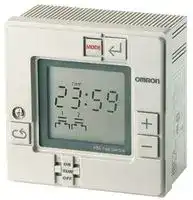


H5L-A
DIGITAL 24 HOUR TIMER
- Manufacturer: OMRON INDUSTRIAL AUTOMATION
- Product type: Hour Meters
- Supply Voltage Min:100VAC; Supply Voltage Max:240VAC; Time Min:24h; Time Max:7Days; Panel Cutout Height:92mm; Panel Cutout Width:92mm; Product Range:-; Power Consumption:4VA 52F4158
- Time Max: 7Days
- Time Min: 24h
- Product Range: -
- Panel Cutout Width: 92mm
- Supply Voltage Max: 240VAC
- Supply Voltage Min: 100VAC
- Panel Cutout Height: 92mm
| Delivery and price | |
|---|---|
| Units per pack | 1 |
| Price | 399.5 € |
| Current stock | 10+ |
| Lead time | 30 days |
**Daily Time Switch H5L**
|**Daily Time Switch**<br>**H5L**||||||
|---|---|---|---|---|---|
|||||CSM_H5L_DS_E_2_2||
|**Weekly Control with a Large Time Display**||||||
|**Easy Programming with Large Display and Interactive**<br>**Functions.**<br>• Easy operation with five keys.<br>• Up to 24 steps of ON/OFF operations can be set.<br>• Power supply freely selectable from 100 to 240 VAC.<br>• Memory protection during power failure for up to 10 years.<br>• Certified for UL and CSA safety standards.<br>• The same setting can be used for multiple-day operation and<br>timer operation.<br>Refer to_Safety Precautions for All Timers_.<br>Refer to_Safety Precautions_onpage 12<br>96 mm<br>96 mm<br>~~a ~~=<br>J||||||
|||For the most recent information on models that have been certified for||||
|||safety standards, refer to your OMRON website.||||
|**Ordering Information**||||||
|||||||
|**Wiring**<br>**Backup power supply function for memory**||**No. of program steps**||**Model**||
|**protection**||||||
|Screw terminals<br>Provided (approx. 10years at 25°C)||24 (Each ON or OFF is considered to be one step.)||H5L-A||
## **S ecifications p**
## ■ **Time Ranges**
|■**Time Ranges**|||
|---|---|---|
|**Rated time**<br>24 hrs x 7 days<br>~~{_~~|**Time setting range**<br>00:00 to 23:59|**Time division**<br>1 min|
|■**Ratings**|||
|**Rated supply voltage**|100 to 240 VAC (50/60 Hz)||
|**Operating voltage range**|85% to 110% of rated supplyvoltage||
|**Power consumption**|Approx. 4 VA at 240 VAC||
|**Control outputs**|15 A at 250 VAC, resistive load at 50°C||
||12 A at 250 VAC, resistive load at 55°C||
||Minimum applied load: 100 mA at 5 VDC (failure level: P, reference value)||
**1**
**H5L**
## ■ **Characteristics**
|■**Characteristics**||
|---|---|
|**Accuracy of operating time**|±0.01%±0.05 s max. (see note 1)|
|**Setting error**||
|**Influence of voltage**||
|**Influence of temperature**||
|**Time accuracy**|±15 s per month (at 25°C)|
|**Insulation resistance**|100 MΩmin.|
|**Dielectric strength**|2,000 VAC, 50/60 Hz for 1 min (between current-carrying terminals and exposed non-current-carrying<br>metal parts and between control power supply circuit and contact control output circuits)<br>1,000 VAC, 50/60 Hz for 1 min (between non-continuous contacts)|
|**Vibration resistance**|Destruction: 10 to 55 Hz with 0.75-mm double amplitude<br>Malfunction: 10 to 55 Hz with 0.5-mm double amplitude|
|**Shock resistance**|Destruction: 300 m/s2(approx. 30G)<br>Malfunction: 100 m/s2(approx. 10G)|
|**Ambient temperature**|Operating:<br>–10°C to 55°C|
|**Ambient humidity**|Operating:<br>35% to 85%|
|**Life expectancy**|100,000 operations min. (15 A at 250 VAC, resistive load)|
|**Approved standards**|UL (File No. E52800), CSA (File No. LR22310)|
|**Weight**|Approx. 350g|
**Note:** The overall error, which includes repeat accuracy, setting error, and variations due to changes in voltage and temperature, is ±0.01% or ±0.05 s max. The accuracy of ±0.01% also indicates the error in the time interval of the set time.
## **En ineerin Data g g**
## **Ambient Operating Temperature and Carry Current**
Note that the upper limit of the ambient operating temperature lowers when a large carry current is being applies as shown below.
**==> picture [147 x 160] intentionally omitted <==**
**----- Start of picture text -----**<br>
l T<br>55 - ot<br>When both circuits are<br>50 energizedeesimultaneously<br>| |<br>| [|]<br>| |<br>40-—_+_________1- 1<br>0 5 10 12 15<br>Carry current AC/DC (A)<br>C)<br>°<br>Upper limit of ambient temperature (<br>**----- End of picture text -----**<br>
**2**
**H5L**
## **Nomenclature**
**==> picture [441 x 147] intentionally omitted <==**
**----- Start of picture text -----**<br>
LCD Mode Key<br>Write Key<br>L sum [iat Tut Pwo teu [Fm] sar J<br>.<br>o-oo Plus Key<br>Note: This figure shows the LCD section with all display items<br>Minus Key being displayed on the screen.<br>es, mts | [=]<br>OO<br>ae<br>Ly<br>Cycle Key Manual override switch<br>**----- End of picture text -----**<br>
## **Key Operation**
|**Key**|**Name**|**Function**|
|---|---|---|
||Mode Key|Changes program mode<br>Curre**n**ttime<br>Firstcircuitoperation<br>[runmace} [i g<br>moce_~[Sningmode”<br>| |Second circuit<br>Second circuit<br>"<br>“1 weekday setting[+]Operation<br>comne node<br>mode<br>setting mode<br>ew|
||Write Key|To write the set data using the Plus and/or Minus Key.<br>Reads out the set program.|
|~~Ce~~|Plus Key<br>~~Ce~~|Changes “day of week” while setting day of week.<br>Changes “hours” or “minutes” while setting current time.<br>When the Plus Key is held down, the displayed digit increments continuously; when the Minus Key is held<br>down, it decrements continuously.<br>When specifying output.<br>The Plus Key specifies output ON while the Minus Key specifies output OFF.<br>Note that if the same key is pressed twice, the output specification becomes invalid; neither ON nor OFF is<br>set.<br>~~Ce~~<br>~~ee~~|
|~~Ce~~<br>~~Be~~|Minus Key<br>~~Ce~~||
|~~Be~~<br>~~ee~~|Cycle Key<br>~~ee~~|Specifies the cycle program. Pressing this key twice causes the set cycle program to be cleared.<br>~~ee~~<br>~~ee~~|
|~~Be~~<br>~~ee~~|Manual override<br>switch<br>~~ee~~|ON:<br>Turns ON output regardless of program<br>RUN: Executes program<br>OFF:<br>Turns OFF output regardless of program<br>First and second circuit can be operated independently.<br>~~ee~~<br>~~ee~~|
**3**
**H5L**
## **O eration p**
## ■ **Programming**
The H5L Weekly Timer has the following six program modes. Use the Mode Key to change the modes. Use the Write Key, Plus Key, Minus Key, and Cycle Key for programming in each mode.
## **Mode Change Sequence**
## **Programming Details**
- To set the current time in the order of "day of week",
- Current "hour" and "minute". time setting 1. Press the Mode Key for longer than 1 s to put the H5L in "TIM ADJ" mode.
- 2. Set "DAY OF WEEK" using the Plus and/or Minus Keys. Then press the Write Key to write the set weekday.
- 3. Set "hour" using the Plus and/or Minus Keys. Then press the Write Key to write the set hour.
- 4. Set "minute" using Plus and/or Minus Keys. Then press the Write Key to write the set minute.
- First To specify first circuit operation in the order of circuit "hour", "minute", and "output ON or OFF" operation setting 1. Press the Mode Key to put the H5L in "PROG 1" mode.
- 2. Set "hour" using the Plus and/or Minus Keys. Then press the Write Key to write the set hour.Set minute" using the Plus and/or Minus Keys. Then press the Write Key to write the set minute.
- 3. Specify "ON" or "OFF" of output using the Plus or Minus Key and press the Write Key to write the set output specification.
- In this manner, set ON time and OFF time as many times as necessary.
- First To set for each weekday whether the program for the first circuit circuit set in the previous step is to be executed or not. weekday 1. Press the Mode Key to put the H5L in "PROG 1" setting "DAY SET" mode. 2. Press the Plus Key to run the first circuit and press the Minus Key for it not to run.
3. Press the Write Key to change day of week. Repeat steps 2 and 3 for Sunday to Saturday.
- Second To specify second circuit operation in the order of "hour", circuit "minute", and "output ON or OFF" operation setting 1. Press the Mode Key to put the H5L in "PROG 2" mode.
- 2. Proceed with the settings in the same manner as in the first circuit operation setting above.
- Second To set for each weekday whether the program for the circuit second circuit set in the previous steps is to be executed weekday or not. setting 1. Press the Mode Key to put the H5L in "PROG 2" "DAY SET" mode.
- 2. Proceed with the settings in the same manner as in the first circuit operation setting above.
- Run the H5L using the set program. In RUN mode, the
- RUN current time and output status are displayed but the operation mode is not displayed. After starting the H5L, the colon between the hour" and minute" blinks to indicate that time count is in execution.
**Note:** The H5L operates in accordance with the program already set even while another program is being set. The output status display ( etc.) during programming displays the setting being rye1 2 programmed. Therefore, note that the output status displayed on the LCD may not agree with the actual output status.
## **Setting Multiple-day Operation**
Example for Turning ON Circuit 1 Every Day from Monday to Friday at 11:50 pm and Turning Circuit 1 OFF at 3:00 am the Next Morning
**==> picture [244 x 67] intentionally omitted <==**
**----- Start of picture text -----**<br>
Sun Mon Tue Wed Thu Fri Sat<br>| LM mi mf.<br>23:50 3:00<br>1. Use the procedure First circuit operation setting given at the left to<br>set the ON time to 23:50 and the OFF time to 3:00.<br>**----- End of picture text -----**<br>
**2.** Use the procedure _First circuit weekday setting_ given at the left to set Monday, Tuesday, Wednesday, Thursday, and Friday.
## **Cycle Program**
In the H5L, the cycle program can be used to repeat ON and OFF of output for a certain period in a predetermined cycle. A cycle program consists of the following four steps: Start time, ON time, OFF time, Stop time
## **Setting A Cycle Program**
Set the four steps of the cycle program in the following procedure.
|Setting<br>start|Setting<br>start|Set the "hour" and "minute" of start<br>time using the Plus and/or Minus Key.|
|---|---|---|
|time<br>Setting<br>ON<br>time<br>|||Set the ON time of the cycle frequency<br>in the order of "hour" and "minute".|
|Setting||Set the OFF time of the cycle frequency|
|OFF<br>time||in the order of "hour" and "minute".|
|Setting<br>stop<br>time||Set the stop time of the cycle program.|
||||
|Normal<br>program<br>mode||On completing settings for the four<br>steps, the H5L returns automatically<br>to normal program mode.|
## **Cautions on Using Cycle Programs**
**1.** When the current time is included within the set cycle period, the cycle operation starts (output turns ON) on completing the cycle program setting (when stop time is written).
**2.** When any of the following occurs during a cycle period, the cycle operation restarts from output ON. Recovery after power failure Current time adjustment
Change of start or stop time of the cycle program during operation. For this reason, if the cycle programs for the first and second circuits are set in such a manner that outputs 1 and 2 have a phase difference, note that the phase difference is changed when any of the conditions above occur as shown in the example below. (Therefore, it is recommended that cycle programs are used sequentially.)
**4**
**H5L**
**==> picture [221 x 68] intentionally omitted <==**
**----- Start of picture text -----**<br>
Recovery after<br>power failure<br>Output 1 Cc] Cc] Power failure KS z=<br>t_<br>Note: Refer to "Programming Output 1 and 2 start<br>simultaneously<br>Example".<br>**----- End of picture text -----**<br>
**3.** The cycle period (from start time to stop time) does not need to be a multiple of the cycle frequency (ON time plus OFF time). The cycle period can be set within a range of 1 min to 24 hrs.
**4.** ON time as well as OFF time can be set within a range of 1 min to 23 hrs 59 min.
**5**
**H5L**
## **Deleting Programming**
## **1. Deleting from Normal Operation Programs (ON Time/OFF Time)**
Call up the output display for the program to be deleted by pressing the Write Key. The minus sign (–) for the output point will flash.
## **2. Deleting from Cyclic Programs**
Four steps will be simultaneously deleted from the cyclic program if the program is called up and then the Cycle and Write Keys are pressed in order. The start time display will remain, but the program will be deleted.
Next, change the display to disable the output using the Plus and Minus Keys. For NC contacts, press the Plus Key and for NO contacts, press the Minus Key. The connecting bar above the contacts will disappear and the display will flash to indicate that the output has been displayed. If the Write Key is pressed at this time, the step will be deleted.
## ■ **LCD Display**
## **LCD Display (Display Example in Each Mode)**
Since the H5L employs interactive programming, the program mode and setting data are displayed on the LCD.
|**Display**|**Mode**|**Display data**|**Display**|**Mode**|**Display data**|
|---|---|---|---|---|---|
|voM<br>'<br>Liam,<br>(tte et<br>ES<br>ears|RUN|Current day of week:<br>Monday<br>Current time:10:11<br>First circuit: OFF<br>Second circuit: ON|!<br>a<br>~<br>i<br>3594<br>on, ~<br>;<br>ae|Second<br>operation time<br>setting|The second circuit turns ON<br>Sunday to Thursday<br>(operation by the set<br>program is executed). It<br>turns OFF on Friday and<br>Saturday (operation by the<br>set program stops).|
|ora<br>|<br>ae!<br>f|Current time<br>setting|Current day of week:<br>Tuesday<br>Current time: 9:31|'<br>2<br>aati||Second<br>Weekday<br>setting|The second circuit turns ON<br>Sunday to Thursday<br>(operation by the set<br>program is executed). It<br>turns OFF on Friday and<br>Saturday (operation by the<br>set program stops).|
|Oe<br>1<br>-Lj-<br>1<br>or<br>eal|First operation<br>time setting|The first circuit turns on at<br>8:15|-e46nm<br>te ty<br>1<br>dal<br>STOP<br>pig<br>Las|Cycle Program<br>setting|The first circuit starts cycle<br>operation at 1:10 (for<br>details, refer to Cycle<br>Program).|
|pest<br>ue [wilh [esi ed<br>.<br>a<br>a|First weekday<br>setting|The first circuit turns OFF<br>on Sunday and Saturday<br>(operation by the set<br>program stops). It turns ON<br>Monday to Friday (operation<br>by the set program is<br>executed).|'<br>\7<br>°<br>§<br>“B25<br>71»<br>ia||Memory over|Indicates that all 24<br>program steps have been<br>written (on writing the 24th<br>step, the data set for the first<br>step is displayed on the<br>LCD).|
**Note:** Meaning of output status indications
:Output ON, ; Output OFF, : Invalid (if an invalid instruction is written to a step, that step will be cleared.)
## ■ **Programming Example**
Be sure to create a timing chart before programming.
## **Operating Timing Chart**
## **First Circuit**
## **Second Circuit**
**6**
**H5L**
## **Example**
## **ON and OFF Programs Cyclic Programs**
In this example, the first circuit is programmed to turn ON at 7:40 and OFF at 19:30. This circuit is operated from Monday through Friday and stopped on Saturday and Sunday.
The second circuit is cyclically operated with each parameter set as follows:
Start time: 6:50 ON time: 5 min OFF time: 20 min Stop time: 20:30
The second circuit is stopped from operating on Sunday and operated from Monday through Saturday. The current time is assumed to be 11:15 a.m. on Tuesday.
## **Writing Program**
Even while being programmed, the timer generates output according to the previous program. If you don’t want an unexpected operation of output relay, turn on (or off) the manual switch.
In the figure, the indicators and digits shown in are blinking.
## **1. Setting Current Time**
To set the current time, "day of the week", "hour", and "minute" must be specified. First, turn on the power to the H5L.
The contents of the memory are cleared on power-up and the TIM ADJ indicator is displayed as shown on the left.As an example, set the time to 11:15 on Tuesday.
Start by setting the day of the week. The blinking indicator indicates the parameter that can be set. Set the current day of the week to Tuesday by pressing the Plus or Minus Key.
When "TUE" is displayed, press the Write Key to store the current day of the week in memory. The "hour" indicator will begin to flash and the day of the week" indicator will stop flashing.
Set the current hour to 11 by pressing the Plus or Minus Key, followed by the Write Key.
At this time, the "minute" indicator will blink. Set the current minute to 15 by pressing the Plus or Minus Key, followed by the Write Key.
This completes the current time setting.
**7**
**H5L**
## **2. First Circuit Operation Setting**
To program the operation of the first circuit, "hour", "minute", and "output" must be specified. Press the Mode Key to place the H5L into PROG 1 mode. The display will be as shown on the left.
Since the first circuit is to be turned ON at 7:40, set the "hour" to 7 by pressing the Plus or Minus Key and then store it in memory by using the Write Key.
The "minute" will start blinking. Set it to 40 by using the Plus or Minus Key and store it in memory by pressing the Write Key.
Now, the output status indicator will blink. Set the output to the ON state with the Plus Key followed by the Write Key. (If the Plus Key is pressed twice at this time, the display will give an invalid indication, and if the Write Key is pressed, this program will be deleted.)
The display returns to the initial state as shown on the left and waits for the next program command to be input.
Since the first circuit should be turned OFF at 19:30, set the hour to 19 and the minute to 30 by using the Plus or Minus Key and then the Write Key.
The output status indicator starts blinking. Set the output to the OFF state using the Minus Key and store it in memory by pressing the Write Key. The display returns to the initial state and waits for the next program command to be input. Now let us turn to the setting of the "day of the week".
## **3. Fist Circuit Day-of-the-week Setting**
By pressing the Mode Key, place the H5L into DAY SET mode. The display will be as shown on the left. Press the Plus Key to operate the first circuit on a particular day of the week and press the Minus Key to stop it. The reverse video (i.e., white characters on a black background) of the day-of-the-week indicators means that the first circuit is operated on that day. The day on which circuit operation is stopped is indicated by bold indicators. Initially, the circuit is set to operates on all the days of the week and the SUN indicator blinks.
In this example, since circuit operation is to be stopped on Sunday, select SUN and press the Minus Key, then store the setting in memory by pressing the Write Key.
The MON indicator will start blinking. Press the Write Key, until the SAT indicator blinks.
Since the first circuit is not to be operated on Saturday, press the Minus Key followed by the Write Key.
The SUN indicator will start blinking again. This completes the setting of all the days of the week for the first circuit.
**8**
**H5L**
## **4. Second Circuit Operation Setting**
Press the Mode Key to place the H5L into PROG 2 mode. The display appears as shown on the left.
In this example, as the second circuit is to be cyclically operated, specify the cycle program by pressing the Cycle Key.
Select the start time by setting the hour to 6 and the minute to 50 using pressing the Plus or Minus Key. Write each set value by pressing the Write Key. The timer will now wait for you to set the ON time (5 min in this example). Press the Write Key to select 0 hrs, then use the Plus or Minus Keys followed by the Write Key to select 5 min. The timer will now wait for the OFF time to be set (20 min in this example). Press the Write Key to select 0 hrs, then use the Plus or Minus Keys followed by the Write Key to select 20 min. The timer will now wait for the cyclic circuit operation stop time to be set (20:30 in this example). Set the hour to 20 using the Plus or Minus Keys, then press the Write Key. Set the minutes to 30 and press the Write Key again.
The programming of the cyclic operation is now complete. The timer will wait for input of a new program as shown. We will now have to set the day of the week for the second circuit.
## **5. Second Circuit Day-of-the Week Setting**
Press the Mode Key to place the H5L into PROG 2, DAY WET mode. Initially, all days of the week are selected (shown by reverse video) and the SUN indicator will be flashing.
In our example, the second circuit is to be operated on all days except Sunday. To inhibit Sunday operation, press the Minus Key while the SUN indicator is flashing. The circuit will now be operated only from Monday to Saturday.
All of the parameters have now been programmed for this example. Press the Mode Key to place the timer into RUN mode. The display will be as shown (assuming five minutes have elapsed while programming). The output status indicators indicate the status of each of the circuit.
**Note:** Set manual override switches 1 and 2 to RUN.
**9**
**H5L**
## **Dimensions**
**Note:** All units are in millimeters unless otherwise indicated.
## **H5L-A**
**==> picture [278 x 118] intentionally omitted <==**
**----- Start of picture text -----**<br>
56.5<br>96<br>42<br>6 14.5<br>4<br>| in—<br>96 12<br>i 35.3 91.9<br>Wu<br>M3.5<br>terminal<br>i screws<br>**----- End of picture text -----**<br>
**==> picture [199 x 7] intentionally omitted <==**
**----- Start of picture text -----**<br>
Dimensions Panel Cutout<br>**----- End of picture text -----**<br>
**Mounting Bracket (Included)**
## **Dimensions**
**==> picture [429 x 287] intentionally omitted <==**
**----- Start of picture text -----**<br>
59.8 (See note 1)<br>68.5 (See note 2)<br>Note: 1. When using mounting track<br>PFP-100N or PFP-50N.<br> 2. When using mounting track<br>PFP-100N2.<br>Mounting track<br>Panel<br>Dimensions Panel Cutout Mounting Bracket (Included)<br>Two, M4 taps<br>_- —_<br>Mounting bracket 1_/ © | Tea<br>|}~————104+0.2————114 ——— |<br>Panel<br>**----- End of picture text -----**<br>
**10**
**H5L**
## ■ **Accessories (Order Separately)**
## **Front Cover**
**Y92A-96A**
**==> picture [62 x 22] intentionally omitted <==**
**----- Start of picture text -----**<br>
16<br>[T 42 WL.<br>**----- End of picture text -----**<br>
## **Mounting Track (Meets DIN EN 50022)**
**PFP-100N/PFP-50N**
> (See note) 25g = 25~ cn (See note 2) ma (See note)
**PFP-100N2**
> Twelve,-25 × 4.5 elliptic holes (See note 2) —,, eS -==>—} 25-1 , (See note) |25~ 9 25S
- **Note:** 1. This dimension is 15 mm on both ends in the case of the PFP-100N but on one end in the case of the PFP-50N.
2. The length l of each mounting track is shown in this table.
3. A total of twelve 25 × 4.5 elliptic holes are provided, with six holes cut from each end of the track at a pitch of 10 mm between holes.
|**PFP-100N**|1 m|
|---|---|
|**PFP-50N**|50 cm|
|**PFP-100N2**|1 m|
## **Installation**
## ■ **Connections**
Connect the power supply between terminals A and B, the load for the first circuit between terminals G and H, and the load for the second circuit between terminals E and F. Terminals C and D are no connects.
**Note:** To each load, connect the power supply for load.
**11**
**H5L**
## **Safet Precautions y**
Refer to _Safety Precautions for All Timers_ .
~~yy~~ ! **CAUTION** Tighten terminal screws to the specified torque of approx. 0.8 N·m (maximum torque: 0.98 N·m). Loose screws may occasionally cause fires or malfunction. ~~en~~ The Time Switch contains a lithium battery (explosion- ~~| )~~ proof). Do not disassemble the Time Switch, deform the Time Switch under pressure, heat the Time Switch to above 100°C, or incinerate the Time Switch. Doing any of these may result in fire or battery rupture.
## **Surface Mounting**
- Use a straight mounting bracket to surface mount the unit.
## ■ **Precautions for Safe Use**
Observe all of the following precautions to maintain safety.
**1.** The Time Switch is not waterproof or oil resistant. Do not use it in locations subject to water or oil.
**2.** Use the following wire to wire the Time Switch: 600-V vinylinsulated wire (solid wire or twisted wire, copper), 14 to 24 AWG
**3.** Do not connect more than two crimp terminals to each Time Switch terminal.
**4.** None of the Time Switch components are user-replaceable, including the battery.
## ■ **Precautions for Correct Use**
Be sure that the capacity of the power supply is large enough, otherwise the Time Switch may not start due to the inrush current (approx. 3 A) that flows for an instant when the power to the Time Switch is turned ON.
## **ON Current and Ambient Temperature (Reference Values)**
**==> picture [245 x 198] intentionally omitted <==**
**----- Start of picture text -----**<br>
If the ON current is too large, the upper limit to the ambient operating<br>temperature must be reduced as shown in the following diagram.<br>a 60<br>55<br>Both circuits ON simultaneously<br>50<br>40<br>0 5 10 12 15 20<br>ON Current (A AC or DC)<br>C)Upper limit to ambient operating temperature (°<br>**----- End of picture text -----**<br>
## **Track Mounting**
- Hook the upper part on the rear surface to the upper edge of the mounting track and press the unit down.
**==> picture [109 x 52] intentionally omitted <==**
**----- Start of picture text -----**<br>
(1) (2)<br>i<br>**----- End of picture text -----**<br>
- To remove the Timer Switch from the DIN Track, pull down on the yellow lever at the back of the Timer Switch.
## **Wiring**
**==> picture [33 x 5] intentionally omitted <==**
**----- Start of picture text -----**<br>
Yellow lever<br>**----- End of picture text -----**<br>
## **Wiring From the Rear**
- Perform wiring from the rear of the unit when the unit is flush mounted. Rage M3.5 terminal screws
- %
## **Wiring From the Front**
- Perform wiring from the front of the unit when the unit is track or surface mounted.
## **Mounting Dimensions**
## **Flush Mounting**
**•** Use a U-shaped mounting bracket to flush mount the unit.
## **Wiring Procedure**
**1.** Loosen the screw on the left side of the front.
**2.** Slide the upper part of the unit approx. 15 mm upward.
**3.** After the terminals appear, perform wiring.
**4.** Return the upper part of the unit to the original position and tighten the screw.
**Note:** Screw tightening torque: 0.98 N·m max.
**12**
**H5L**
ALL DIMENSIONS SHOWN ARE IN MILLIMETERS.
To convert millimeters into inches, multiply by 0.03937. To convert grams into ounces, multiply by 0.03527.
In the interest of product improvement, specifications are subject to change without notice.
**13**
## **Read and Understand This Catalog**
Please read and understand this catalog before purchasing the products. Please consult your OMRON representative if you have any questions or comments.
## **Warranty and Limitations of Liability**
- **WARRANTY** OMRON's exclusive warranty is that the products are free from defects in materials and workmanship for a period of one year (or other period if specified) from date of sale by OMRON.
**==> picture [481 x 31] intentionally omitted <==**
**----- Start of picture text -----**<br>
OMRON MAKES NO WARRANTY OR REPRESENTATION, EXPRESS OR IMPLIED, REGARDING NON-INFRINGEMENT, MERCHANTABILITY, OR<br>FITNESS FOR PARTICULAR PURPOSE OF THE PRODUCTS. ANY BUYER OR USER ACKNOWLEDGES THAT THE BUYER OR USER ALONE HAS<br>DETERMINED THAT THE PRODUCTS WILL SUITABLY MEET THE REQUIREMENTS OF THEIR INTENDED USE. OMRON DISCLAIMS ALL OTHER<br>WARRANTIES, EXPRESS OR IMPLIED.<br>**----- End of picture text -----**<br>
**==> picture [479 x 33] intentionally omitted <==**
**----- Start of picture text -----**<br>
LIMITATIONS OF LIABILITY<br>OMRON SHALL NOT BE RESPONSIBLE FOR SPECIAL, INDIRECT, OR CONSEQUENTIAL DAMAGES, LOSS OF PROFITS OR COMMERCIAL LOSS<br>IN ANY WAY CONNECTED WITH THE PRODUCTS, WHETHER SUCH CLAIM IS BASED ON CONTRACT, WARRANTY, NEGLIGENCE, OR STRICT<br>LIABILITY.<br>**----- End of picture text -----**<br>
In no event shall the responsibility of OMRON for any act exceed the individual price of the product on which liability is asserted. IN NO EVENT SHALL OMRON BE RESPONSIBLE FOR WARRANTY, REPAIR, OR OTHER CLAIMS REGARDING THE PRODUCTS UNLESS OMRON'S ANALYSIS CONFIRMS THAT THE PRODUCTS WERE PROPERLY HANDLED, STORED, INSTALLED, AND MAINTAINED AND NOT SUBJECT TO CONTAMINATION, ABUSE, MISUSE, OR INAPPROPRIATE MODIFICATION OR REPAIR.
## **Application Considerations**
**==> picture [508 x 457] intentionally omitted <==**
**----- Start of picture text -----**<br>
SUITABILITY FOR USE<br>OMRON shall not be responsible for conformity with any standards, codes, or regulations that apply to the combination of products in the customer's<br>application or use of the products.<br>At the customer's request, OMRON will provide applicable third party certification documents identifying ratings and limitations of use that apply to the<br>products. This information by itself is not sufficient for a complete determination of the suitability of the products in combination with the end product,<br>machine, system, or other application or use.<br>The following are some examples of applications for which particular attention must be given. This is not intended to be an exhaustive list of all possible<br>uses of the products, nor is it intended to imply that the uses listed may be suitable for the products:<br> Outdoor use, uses involving potential chemical contamination or electrical interference, or conditions or uses not described in this catalog.<br> Nuclear energy control systems, combustion systems, railroad systems, aviation systems, medical equipment, amusement machines, vehicles,<br>safety equipment, and installations subject to separate industry or government regulations.<br> Systems, machines, and equipment that could present a risk to life or property.<br>Please know and observe all prohibitions of use applicable to the products.<br>NEVER USE THE PRODUCTS FOR AN APPLICATION INVOLVING SERIOUS RISK TO LIFE OR PROPERTY WITHOUT ENSURING THAT THE<br>SYSTEM AS A WHOLE HAS BEEN DESIGNED TO ADDRESS THE RISKS, AND THAT THE OMRON PRODUCTS ARE PROPERLY RATED AND<br>INSTALLED FOR THE INTENDED USE WITHIN THE OVERALL EQUIPMENT OR SYSTEM.<br>PROGRAMMABLE PRODUCTS<br>OMRON shall not be responsible for the user's programming of a programmable product, or any consequence thereof.<br>Disclaimers<br>CHANGE IN SPECIFICATIONS<br>Product specifications and accessories may be changed at any time based on improvements and other reasons.<br>It is our practice to change model numbers when published ratings or features are changed, or when significant construction changes are made.<br>However, some specifications of the products may be changed without any notice. When in doubt, special model numbers may be assigned to fix or<br>establish key specifications for your application on your request. Please consult with your OMRON representative at any time to confirm actual<br>specifications of purchased products.<br>DIMENSIONS AND WEIGHTS<br>Dimensions and weights are nominal and are not to be used for manufacturing purposes, even when tolerances are shown.<br>PERFORMANCE DATA<br>Performance data given in this catalog is provided as a guide for the user in determining suitability and does not constitute a warranty. It may represent the<br>result of OMRON’s test conditions, and the users must correlate it to actual application requirements. Actual performance is subject to the OMRON<br>Warranty and Limitations of Liability.<br>ERRORS AND OMISSIONS<br>The information in this document has been carefully checked and is believed to be accurate; however, no responsibility is assumed for clerical,<br>typographical, or proofreading errors, or omissions.<br>2012.8<br>In the interest of product improvement, specifications are subject to change without notice.<br>**----- End of picture text -----**<br>
## **OMRON Corporation Industrial Automation Company**
**http://www.ia.omron.com/**
(c)Copyright OMRON Corporation 2012 All Right Reserved.
Updated at April 22, 2026
With a legacy spanning over 80 years, Omron Industrial Automation is a globally recognized leader in the manufacture of advanced industrial control and automation components. Renowned for their reliability and engineering excellence, Omron delivers comprehensive solutions that enhance efficiency, machine safety, and precision across a wide range of manufacturing environments. Our extensive portfolio of Omron products is heavily focused on their industry-leading sensing and switching technologies. We offer a vast selection of sensors, excelling specifically in high-performance proximity sensors, light sensors, and temperature sensors. Complementing this range are robust switching solutions, featuring a deep inventory of power relays, solid-state relays, safety relays, and essential relay accessories designed for demanding operational requirements. Beyond sensing and switching, Omron is highly regarded for its precision automation and process control equipment. Our selection features highly accurate temperature controllers, versatile process controllers, and sophisticated panel displays and instrumentation. To support these fundamental systems, we also supply dependable Omron power supplies, notably AC/DC converters, alongside vital connectivity components like DIN rail terminal blocks to ensure secure, efficient, and complete industrial setups.
About Novapart
Novapart is a B2B electronic component broker specialising in stock shortages and cost reduction. We source hard-to-find parts and identify compliant alternatives across a catalogue of 410,000+ components from 500+ manufacturers.
Learn more →Stock Shortage Specialist
When a component is unavailable, discontinued or has an unacceptable lead time, we tap into our network of vetted European and Asian distributors to source what you need — without compromising on quality or traceability.
Request a quote →Compliant Alternatives
We identify pin-to-pin, electrically equivalent substitutes that meet the same certifications (RoHS, AEC-Q100, REACH) as your original specification — validated against datasheets, not just part numbers. Often at a lower cost.
BOM Analysis service →