


H5FB
TIMER
- Manufacturer: OMRON INDUSTRIAL AUTOMATION
- Product type: Hour Meters
- Time Max: 7Days
- Time Min: 24h
- Panel Cutout Width: 45mm
- Supply Voltage Max: 240VAC
- Supply Voltage Min: 100VAC
- Panel Cutout Height: 45mm
| Delivery and price | |
|---|---|
| Units per pack | 5 |
| Price | 282.81 € |
| Current stock | 10+ |
| Lead time | 30 days |
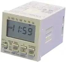
**Digital Daily Time Switch H5F**

CSM_H5F_DS_E_3_3

## **Daily Time Control with Simple Operations**

- Specify the operation days. (However, you can set only one pattern of operation days and specified days.)

**P S E** < C E

- Up to 12 ON/OFF operations (24 for pulse-output operation).

- Special holidays can be handled easily with the holiday setting function.

- Adjustments for sudden schedule changes can be made easily using output override and automatic return operation.

- The operation program can be checked easily with the program check function.

- Enables pulse output operation and summer time setting.

- Incorporates finger-safe terminals.

- Conforms to UL, CSA, and CE marking.

- Meets a variety of mounting requirements: flush mounting, surface mounting, and DIN track mounting.

For the most recent information on models that have been certified for safety standards, refer to your OMRON website.

## **Model Number Structure**

## ■ **Model Number Legend**

## **H5F-** @ **B**

**1 2**

## **1. Mounting method**

None: Flush mounting

- F: Surface mounting

- K: Surface mounting/track mounting

## **2. Language**

B: English

## **Orderin Information g**

## ■ **List of Models**

|■**List of Models**|||
|---|---|---|
|**Wiring**|**Mounting method**|**Model**|
|Screw terminals|Flush mounting|H5F-B|
||Surface mounting|H5F-FB|
||Surface mounting/track mounting|H5F-KB|


## ■ **Accessories (Order Separately)**

|■**Accessories (Order Separately)**|■**Accessories (Order Separately)**||
|---|---|---|
|**Name**||**Models**|
|**Soft cover**||Y92A-48F1|
|**Hard cover**|**For H5F-B**|Y92A-48|
||**For H5F-FB/-KB**|Y92A-48E (See note 1.)|
|**Flush Mounting Adapter(See note 2.)**||Y92F-30|
|**Mounting Track**|**50 cm(l)**×**7.3 mm(t)**|PFP-50N|
||**1 m(l)**×**7.3 mm(t)**|PFP-100N|
||**1 m(l) **×**16 mm(t)**|PFP-100N2|
|**End Plate**||PFP-M|
|**Spacer**||PFP-S|


- **Note: 1.** Supplied with H5F-KB model.

   **2.** Supplied with H5F-B (flush-mounting) model.

**1**

**H5F**

## **S ecifications p**

## ■ **Ratings**

|**Rated supply voltage**|100 to 240 VAC (50/60 Hz)|
|---|---|
|**Operating voltage range**|85% to 110% of rated supplyvoltage|
|**Power consumption**|Approx. 2.4 VA at 264 VAC|
|**Control outputs**|Contact output: SPST-NO, 15 A at 250 VAC, resistive load, 10 A at 24 VDC, resistive load<br>Minimum applied load: 100 mA at 5 VDC (failure level: P, reference value)|
||NEMA A300 Pilot Duty, 1/3 HP at 120 VAC|
|**External connections**|Screw terminals (M3.5 screw)|
|**Terminal screw tightening torque**|0.98 to 1.17 N · m|


## ■ **Characteristics**

|**Accuracy of operating time**|±0.01%±0.05 s max. (see note 1)|
|---|---|
|**Setting error**||
|**Influence of voltage**||
|**Influence of temperature**||
|**Influence of EMS. (at EN61326-1)**||
|**Time accuracy**|±15 s per month(at 25°C)|
|**Memory protection**|Continuous use: 5 years min. (at 25°C); Power-interruption rate of 50%: 10 years min. (at 25°C) (see note 2)<br>(lithium battery)|
|**Insulation resistance**|100 MΩmin. (between current-carrying terminals and exposed non-current-carrying metal parts, between operating<br>power supply circuit and control output circuit and between non-continuous contacts)|
|**Dielectric strength**|2,000 VAC, 50/60 Hz for 1 min (between current-carrying terminals and exposed non-current-carrying metal parts and<br>between operating power supply circuit and control output circuit)<br>1,000 VAC, 50/60 Hz for 1 min (between non-continuous contacts)|
|**Noise immunity**|1.5 kV (between power terminals)<br>Square-wave noise by noise simulator (pulse width: 100 ns/1μs, 1-ns rise)|
|**Vibration resistance**|Destruction:10 to 55 Hz with 0.375-mm single amplitude, four cycles each in three directions (8 minutes per cycle)<br>Malfunction:10 to 55 Hz with 0.25-mm single amplitude for 10 minutes each in three directions|
|**Shock resistance**|Destruction:300 m/s23 times each in 6 directions<br>Malfunction:100 m/s23 times each in 6 directions|
|**Ambient temperature**|Operating:–10°C to 55°C (with no icing)<br>Storage: –25°C to 65°C (with no icing)|
|**Ambient humidity**|Operating: 35% to 85%|
|**Life expectancy**|Mechanical (at 20°C):<br>100,000 operations min.<br>Electrical (at 20°C):<br>50,000 operations min. (15 A, 250 VAC, resistive load)<br>50,000 operations min. (1 HP, 250 VAC, motor load)<br>50,000 operations min. (10 A, 250 VAC, inductive load (cosφ= 0.7))<br>50,000 operations min. (100 W, 100 VAC, lamp load)<br>10,000 operations min. (300 W, 100 VAC, lamp load)|
|**Approved safety standards**|UL508/Listing, CSA C22.2 No. 14, conforms to EN61010-1 (Pollution degree 2/overvoltage category II)<br>Conforms to VDE0106/P100 (finger protection).<br>Conforms to Electrical Appliance and Material Safety Law (for Japan)|
|**EMC**|(EMI)<br>EN61326-1 (See note 3.)<br>Emission Enclosure:<br>EN55011 Group 1 class A<br>Emission AC mains:<br>EN55011 Group 1 class A<br>(EMS)<br>EN61326-1 (See note 3.)<br>Immunity ESD:<br>EN61000-4-2:<br>4 kV contact discharge (level 2)<br>8 kV air discharge (level 3)<br>Immunity RF-interference:<br>EN61000-4-3:<br>10 V/m (Amplitude-modulated, 80 MHz to 1 GHz,<br>1.4 to 2 GHz) (level 3)<br>Immunity Conducted<br>Disturbance:<br>EN61000-4-6:<br>10 V (0.15 to 80 MHz) (according to EN61000-6-2)<br>Immunity Burst:<br>EN61000-4-4:<br>2 kV power-line (level 3)<br>1 kV I/O signal-line (level 4)<br>Immunity Surge:<br>EN61000-4-5:<br>1 kV line to lines (power and output lines) (level 2);<br>2 kV line to ground (power and output lines) (level 3)<br>Immunity Voltage Dip/Interruption:<br>EN61000-4-11: 0.5 cycle, 100% (rated voltage)<br>Immunity Magnetic Power Field:<br>EN61000-4-8:<br>30 A/m|
|**Case color**|Lightgray (Munsell 5Y7/1)|
|**Weight**|H5F-B: approx. 115g; H5F-KB: approx. 160g; H5F-FB: approx. 130g|


- **Note: 1.** The total error including the repeat accuracy, setting error, variation due to voltage change, and variation due to temperature change is ± 0.01% ± 0.05 s max. ± 0.01% also indicates an error in the time interval of a set time.

   **2.** The total time when power is not being supplied.

   **3.** Industrial electromagnetic environment (EN/IEC 61326-1 Table 2)

**2**

**H5F**

## **Connections**

## ■ **Terminal Arrangement**

**==> picture [424 x 222] intentionally omitted <==**

**----- Start of picture text -----**<br>
Flush Mounting Models Surface Mounting Models Surface Mounting/Track Mounting Models<br>H5F-B H5F-FB H5F-KB<br>(Front View) (Front View)<br>(Rear View)<br>Power source H5F TIME SWITCH<br>100 to 240 VAC SU   MO   TU   WE   TH    FR    SA<br>PM 3 00<br>POWEROUT ONPW PM  5 00 SU   MO   TU   WE   TH    FR    SA H5F TIME SWITCH<br>OUT TMR/ [P] MODE h m/    WDP<br>ON<br>AUTOOFF CLR+1h HOLIDAYSELECT TESTd WRITE POWEROUT PMONPW 3 PM00 5 00<br>OUT TMR/ [P] MODE h m/    WDP<br>ON<br>AUTO CLR SELECT d WRITE<br>OFF<br>+1h HOLIDAY TEST<br>Load Power supply<br>of load<br>Power source Load Power supplyof load<br>100 to 240 VAC<br>Power source Load Power supplyof load<br>100 to 240 VAC<br>**----- End of picture text -----**<br>


## **Note: 1.** The Time Switch uses M3.5 terminals.

**2.** The Time Switch output is no-voltage contact output. An external power supply is required to drive the load.

**3.** Applicable wire: 600-V vinyl-insulated wire (solid wire or twisted wire, copper), 14 to 24 AWG, 2 wires max. per terminal.

**4.** Applicable tightening torque: 0.98 to 1.17 N·m.

**5.** Recommended fuse: T2A, 250 VAC, time delay, low breaking capacity.

## **O eration p**

## ■ **Operation**

|■**Operation**||
|---|---|
|**Operation method**|Digital quartz|
|**Time range**|24 h×7 days (Operation days can be specified.)|
|**Operation**|1. Daily operation (Multiple-day operation possible.)<br>2. Pulse-output operation (Pulse width can be set in units of 1 s from 1 to 59 s and in units of 1 min<br>from 1 to 60 min.)<br>3. Partial operation on specified day (One or some of the operations for certain days can also be<br>executed on other days.)<br>4. Forced ON/OFF operation<br>5. Holiday operation<br>6. Output override and automatic return operation|
|**Display**|1. Day, hours (12-hour (am/pm) or 24-hour clock), minutes (0:00 to 11:59 a.m./ 0:00 to 11:59 p.m.,<br>0:00 to 23:59)<br>2. Digital display by LCD. Character height: 8 mm<br>3. Digital display of present time and time schedules for operation<br>4. Timingchart displayof present time and time schedules for operation|
|**Other functions**|Program check function, summer time function|
|**Number of circuits**|1 independent circuit|
|**Minimum setting unit**|1 min|
|**Minimum set interval**|1 min|
|**Number of operations that can be set**|24 (see note)|


**Note:** Up to 12 ON/OFF operations are possible per day. (For pulse-output operation, the number is 24.)

**3**

**H5F**

## ■ **Operation Functions**

|■**Operation Functions**|■**Operation Functions**|■**Operation Functions**||
|---|---|---|---|
|**Timer operation (ON/OFF operation)**<br>ON time<br>OFF time|||Controls the output according to preset of ON and OFF times<br>**•** Minimum setting unit: 1 min<br>**•** Up to 12 ON/OFF operations are possible per day.|
|**Pulse-output operation**<br>ON time<br>Pulse width|||Output turns ON for a fixed period (pulse width) at the set time.<br>**•** Pulse width: 1 to 59 s, or 1 to 60 min. (The same pulse width setting is used for all types of<br>output operation.)<br>**•** The pulse width can be set in units of 1 s or 1 min.<br>**•** Up to 24 pulse-output operations are possible per day.|
|||||
|||||
|**Forced**|**ON/OFF operation**||Forcibly turns ON/OFF the output by the output ON/OFF switch.|
|**Override and automatic return operation**<br>Output<br>operation<br>Regular<br>program<br>Start of override and<br>automatic return operation|||Using the output ON/OFF switch and the Write Key, control output is held in the ON state until<br>the next OFF time.<br>**•** It is also possible to hold the control output in the OFF state until the next ON time.<br>**•** Operation after the output turns OFF (or ON) will be based on the regular program.<br>**•** This function can be used with pulse-output operation.|
|**Partial operation on specified day**<br>Operation on<br>operation day<br>Operation on<br>specified day<br>Regular<br>program<br>Program 1<br>(special)<br>Program 2|||The Time Switch operates according to only some of the programs on a user-specified day.<br>(Convenient, for example, for executing a half-day operation on Saturday.)<br>**•** It is not possible to set operation to be executed only on the specified day.<br>**•** Only one pattern of specified days can be set.<br>**•** This function can be used with pulse-output operation.|
|**Holiday setting**<br>Operation from<br>next week<br>Operation in<br>present week<br>Operation on<br>operation day<br>Regular<br>program<br>Operation<br>on holiday|||It is possible to set a day in the present week as a holiday (i.e., a non-operation day: output<br>OFF regardless of the settings). When that day has passed, operation will continue according<br>to the regular program, and operation will be executed as normal on that day from the follow-<br>ing week<br>**•** This function can be used with pulse-output operation.|


**Note:** Both the timer operation and the pulse-output operation cannot be programmed together.

## ■ **Operation When Power Turns OFF**

**1.** The time and settings are backed up using a lithium battery.

**2.** The display stays ON but the output turns OFF.

**3.** Settings for all types of operation except override and automatic return operation are possible.

**4**

**H5F**

## **Nomenclature**

## **Front Panel**

|**Front Panel**|**Front Panel**|**Front Panel**||||||||||||
|---|---|---|---|---|---|---|---|---|---|---|---|---|---|
|HOutput ON/OFF<br>Switch<br>GCLR/+1h Key<br>ITMR/     Key<br>P|||||AMode Key<br>Bh Key<br>Cm/    WD Key<br>DWrite Key<br>Ed/Test Key<br>FSelect/Holiday Key<br>P<br>(Actual Size)<br>**H5F TIME SWITCH**<br>SU MO TU WE TH FR SA<br>WRITE<br>m/ WD<br>d<br>h<br>SELECT<br>MODE<br>CLR<br>TEST<br>HOLIDAY<br>+1h<br>TMR/<br>P<br>P|||||||||
|||||OUT<br>POWER|**H5F TIME SWITCH**<br>SU MO TU WE TH FR SA|||||||||
|||||||||||||||
||Key<br>P|||ON<br>OUT|TMR||h<br>MODE<br>/<br>P||||m/ WD<br>P||Bh Ke<br>Cm/<br>P|
|||||||||||||||
||||<br>e|AUTO<br>OFF|WRITE<br>d<br>SELECT<br>CLR<br>TEST<br>HOLIDAY<br>+1h|||||||||
|||||||||||||||
|||||||||||||||
|||||||||||||||
|**No.**||||**Name**|||||||||**Function**|
|A||Mode Key|||||||||Switches between time adjustment mode, the operation settingmodes, and run mode.|||
|B||h (Hour) Key|||||||||Sets hours or switches between 12-hour (am/pm) and 24-hour display.|||
|C||m/    WD (Minute/Pulse Time Width) Key<br>P|||||||||Sets minutes or a pulse time width.|||
|D||Write Key|||||||||Writes the set data to memoryor confirms settings with the program check function.|||
|E||d/Test (DayShift/Program Test) Key|||||||||Moves the cursor to specifya dayor starts the program check function.|||
|F||Select/HolidayKey|||||||||Specifies or cancels a specified dayor switches to holidaysettingmode.|||
|G||CLR/+1h (Clear/Summer Time) Key|||||||||Erases the set data and initializes the dayof operation or sets/clears summer time.|||
|H||Output ON/OFF switch|||||||||ON:<br>Turns on the output regardless of the setting.<br>AUTO: Turns on/off the output according to the setting.<br>OFF:<br>Turns off the output regardless of the setting.<br>Override and automatic return operation can be executed by using this key in combina-<br>tion with the Write Key.|||
|I||TMR/      (Timer/Pulse output) Key<br>P|||||||||Selects timer operation or pulse-output operation.|||


## **Display**

**==> picture [436 x 193] intentionally omitted <==**

**----- Start of picture text -----**<br>
Time Adjustment Mode Indicator Present Day Indicator<br>Operation Day Indicator<br>SU MO TU WE TH FR SA Lit: Operation day<br>Not lit: Non-operation day<br>Displays the Present Time,  Flashing: Specified operation day<br>Operation Time, and Time Width   S Partial Operation on Specified Day Indicator<br>AM<br>Output Indicator PM sm Pulse Width Unit Indicator<br>Power Indicator Lit when control output is ON. PWON P AMPM +1hP Summer Time Indicator Lit when set to summer time.<br>Lit when power is supplied<br>Operation Setting Mode Indicator<br>to the Time Switch.<br>Next Operation Indicators<br>Pulse Operation Indicator Run mode:  Displays the direction (i.e., ON or<br>Lit: Pulse-output operation OFF) and time of the next output<br>Not lit: Timer operation operation.<br>Operation time setting mode: Displays the program number for<br>the setting.<br>Holiday setting mode:  Displays hday (hday) when the<br>Time Switch is in holiday setting<br>mode.<br>Program check:  Displays test (test) during<br>program check.<br>**----- End of picture text -----**<br>


**5**

**H5F**

## **Dimensions**

## **Note:** All units are in millimeters unless otherwise indicated.

## **H5F-B (provided with Y92F-30 Flush Mounting Adapter) (Flush Mounting)**

**==> picture [497 x 592] intentionally omitted <==**

**----- Start of picture text -----**<br>
Y92A-48 Hard Cover (sold separately)<br>63.7 Panel Cutout Dimensions<br>48 6 14 Terminal cover (provided) (according to DIN43700)<br>48 50.6 37.7 44.8 45+0.5<br>P P<br>84.8 Note:  The Time Switch  45 [+0.5]<br>88.7 uses M3.5  Note:  Recommended panel thickness: 1 to 5 mm.<br>terminals.<br>H5F-FB<br>(Surface Mounting)<br>49<br>50 42.1 Mounting Dimensions 1.5<br>5<br>50<br>(50)<br>P P<br>92 76<br>(92)<br>Y92A-48E<br>Hard Cover<br>(sold separately)<br>M4 tapping screws provided.<br>Terminal cover(provided) 31 Note:  The Time Switch uses M3.5     Approximate pilot hole dimensions:   Panel thickness of 0.8 to 1.2 mm: 3.6-mm dia.<br>terminals.    Panel thickness of 1.6 to 4.0 mm: 3.7-mm dia.<br>Wiring cutout sections:<br>   Cut out as required for wiring.<br>H5F-KB<br>(Surface/Track Mounting)<br>Mounting Hole Cutout Dimensions<br>73 25<br>50 42<br>Y92A-48E<br>Hard Cover<br>(provided)<br>(101.2) 117.4<br>101.2 68 50 35.3 90 104 to 106<br>P P<br>(50.5)<br>50.5 43.1<br>60<br>Terminal cover (provided) M4 tapping screws provided.<br>   Approximate pilot hole dimensions:<br>   Panel thickness of 0.8 to 1.2 mm: 3.6-mm dia.<br>   Panel thickness of 1.6 to 4.0 mm: 3.7-mm dia.<br>H5F TIME  SWITCH<br>PM 5 00<br>ONPW  3 00<br>PM<br>H5F TIME  SWITCH<br>ONPW<br>PM  3 00<br>PM  5 00<br>1 2 100 to 240VAC2.4VA max.50/60Hz 3 4 15A10ARES.250VAC24VDC<br>1 2 2.4VA max. 3 4 RES.<br>SU MO TU WE TH FR SA<br>SU MO TU WE TH FR SA<br>SU MO TU WE TH FR SA<br>H5F TIME  SWITCH<br>PM  3 00<br> 5 00<br>ONPW PM<br>AUTOOFFON<br>AUTOOFFON<br>OUT<br>OUT CLR+1h HOLIDAYSELECTMODE TESTdh m/    WDSET<br>OUT<br>OUT CLR+1h HOLIDAYSELECTMODE TESTdh m/    WDSET<br>TMR/<br>TMR/<br>POWER<br>POWER<br>m/    WD<br>SET<br>TEST<br>TMR/<br>OUT<br>OUT MODE h<br>CLR SELECT d<br>+1h HOLIDAY<br>AUTOOFFON<br>POWER<br>**----- End of picture text -----**<br>


## **H5F-FB (Surface Mounting)**

## **H5F-KB (Surface/Track Mounting)**

**6**

**H5F**

## ■ **Accessories (Order Separately)**

**Note:** Depending on the operating environment, resin products may deteriorate, contract, or harden. They must be replaced on a regular basis.

## **Soft Cover**

## **Y92A-48F1**

## **Hard Cover (provided with H5F-KB)**

**Y92A-48 (for H5F-B) Y92A-48E (for H5F-FB/-KB)** =

Settings can be changed by pressing on the front of the Cover. The settings are harder to change, however, with the Cover mounted. Confirm that this does not hamper operation. Although the Soft Cover provides protection equivalent to IP54F, do not use the Time Switch in locations where it may be directly subject to splashes of oil.

## **Flush Mounting Adapter (provided with H5F-B)**

## **Y92F-30**

The Flush Mounting Adapter can be purchased individually if it is lost or damaged.

**==> picture [471 x 136] intentionally omitted <==**

**----- Start of picture text -----**<br>
Mounting Track<br>PFP-100N, PFP-50N PFP-100N2<br>16<br>7.3±0.15<br>4.5<br>4.5<br>35±0.3 27±0.15 35±0.3 27 24 29.2<br>15 25 10 25 1,000 (500) 25 10 25 * £ 1 15 25 10 25 1,000 25 10 25 15 nee 1 1.5<br>(see note)<br>**----- End of picture text -----**<br>


**==> picture [218 x 8] intentionally omitted <==**

**----- Start of picture text -----**<br>
Note:  The values shown in parentheses are for the PFP-50N.<br>**----- End of picture text -----**<br>


**==> picture [443 x 121] intentionally omitted <==**

**----- Start of picture text -----**<br>
End Plate Spacer<br>PFP-M PFP-S<br>16<br>10 5 12<br>6.2<br>1.8<br>rt tr Ty<br>1<br>50 35.5 35.3 34.8<br>1.8 44.3<br>11.5 1.3<br>10 M4 x 8<br>pan head  4.8 16.5<br>screw<br>**----- End of picture text -----**<br>


**7**

**H5F**

## **Precautions**

Refer to _Safety Precautions for All Timers_ .

## ! **CAUTION**

Do not touch any of the terminals while power is being supplied. Doing so may result in electric shock. Be sure to mount the terminal cover after wiring.

Do not use the Time Switch in locations subject to flammable or explosive gases. Doing so may result in explosion.

Do not disassemble, repair, or modify the Time Switch. Doing so may result in electric shock, fire, or malfunction.

⋅ Tighten terminal screws to the specified torque (approx. 0.98 N m). Loose screws may occasionally cause fires or malfunction. (Maximum ⋅ torque: 1.17 N m)

Before changing times or other settings while power is being supplied, either turn OFF the power on the load side or set the output ON/OFF switch to OFF and confirm the safety of the system.

The life expectancy of the output relays depends on the switching capacity and switching conditions. Consider the actual application conditions and use the Time Switch within the rated load and electrical service life. If using the Time Switch beyond its ratings is unavoidable, use it together with an electromagnetic switch or contactor as shown in the following diagram.

**==> picture [130 x 94] intentionally omitted <==**

**----- Start of picture text -----**<br>
Electromagnetic Power supply Power supply<br>contactor or<br>electromagnetic<br>switch<br>Circuit<br>H5F<br>Load<br>Crossover<br>**----- End of picture text -----**<br>


Using the Time Switch beyond its life expectancy may result in contact deposition or burning.

Do not disassemble the Time Switch, deform the Time Switch by applying pressure, heat the Time Switch to temperatures above 100°C, or incinerate the Time Switch. Doing any of these may cause the built-in lithium battery to ignite or rupture.

## ■ **Wiring**

- Be sure to wire the terminals correctly.

- Do not connect more than two crimp terminals to each Time Switch terminal. Faulty contact may result in burn injury or fire.

- Perform wiring using appropriate wires of the type specified in this document. Using a different type of wire may result in burn injury or fire due to abnormal heat generation.

## ■ **Power Supplies**

- Make sure that the fluctuation of the supply voltage is within the permissible range.

- Make sure that the voltage applied is within the specified range, otherwise the internal elements of the Time Switch may be damaged.

- Apply the power supply voltage through a breaker, relay or switch in such a way that the voltage reaches a fixed value immediately, otherwise they may not be reset or a Time Switch error may result.

## ■ **Operating Environment**

- Do not use the Time Switch in locations where condensation may occur due to high humidity or where temperature changes are severe.

- Do not leave the Time Switch for long periods (i.e., one month or longer) at a high temperature with output current in the ON state. Doing so may result in the premature deterioration of internal components (e.g., electrolytic capacitors).

- Separate the Time Switch from any potential sources of noise, such as high-voltage lines. When using inductive loads (e.g., electromagnetic relays), connect noise-absorbing elements (resistor and capacitor) to both ends of the coil.

- Separate the Time Switch from the source of static electricity when using the Time Switch in an environment where a large amount of static electricity is produced (e.g., forming compounds, powders, or fluid materials being transported by pipe).

- Use the Time Switch within the ratings specified for temperature and humidity.

- Do not use the Time Switch in environments subject to shocks or vibration beyond the ranges specified in this document.

- Do not use the Time Switch in locations subject to dust, corrosive gases, or direct sunlight.

- Store at the specified temperature. If the H5F has been stored at a temperature of less than −10°C, allow the H5F to stand at room temperature for at least 3 hours before use.

- This Time Switch is not waterproof or oil-proof. Do not use it in locations where water or oil may enter the Time Switch interior.

- Organic solvents (such as paint thinner), as well as very acidic or basic solutions might damage the outer casing of the H5F.

## ■ **Installation**

- Mounting the Time Switches side-by-side may reduce the life expectancies of internal components.

- When using heaters, be sure to use a thermal switch for the load circuit.

- When driving an inductive load (e.g., coil), a surge voltage is generated when the contacts (i.e., Time Switch output) are switched, and in some cases this may damage other devices connected to the Time Switch or the same line. Absorb the surge with a capacitor and resistor as shown in the following diagram.

**==> picture [100 x 58] intentionally omitted <==**

**----- Start of picture text -----**<br>
Time Switch output<br>C<br>Power supply Inductiveload<br>R<br>**----- End of picture text -----**<br>


As a rough guide, the capacitor (C) and resistor (R) should have the following specifications:

- C: 0.5 to 1 µF for a switching current of 1 A

- R: 0.5 to 1 Ω for a switching voltage of 1 V

Use a capacitor with a dielectric strength appropriate for the power supply voltage. Use an AC-type capacitor with AC circuits. There may be cases where, due to inconsistencies in the nature and characteristics of the load, delays in restoring the load may cause problems. Be sure to confirm that correct operation is possible under the actual operating conditions.

- When the power is turned ON, an inrush current will flow for a short time (approx. 2 A for 0.3 ms at 264 VAC). Depending on the power supply capacity, operation may not start. Be sure to use a power supply with a sufficient capacity and a breaker.

**8**

**H5F**

## ■ **Precautions for EN61010-1 Conformance**

The H5F Time Switch conforms to EN61010-1 provided that the following conditions are satisfied:

Basic insulation is provided between the power supply and output terminals of the H5F.

- Output terminals are connected to devices without exposed charged parts.

- Output terminals are connected to devices with basic insulation that is suitable for the maximum operating voltage.

## ■ **Others**

None of the Time Switch components are user-replaceable, including the battery.

**9**

**H5F**

## **O eratin Method p g**

## ■ **Operating Method**

## **Selecting the Mode**

All of the modes can be selected using MODE , HOLIDAY , and TEST Keys.

**==> picture [233 x 310] intentionally omitted <==**

**----- Start of picture text -----**<br>
• The days and times  • Set a special day<br>when output will  when the Time<br>actually turn  Switch will not<br>ON/OFF are  operate temporarily<br>displayed<br>chronologically.<br>Program check<br>function Holiday Setting Mode<br>test hday<br>TEST TEST (2 s min.) HOLIDAY HOLIDAY (2 s min.)<br>(See note 1.)<br>Run Mode • Control output<br>operates according<br>(See note 2.) to the settings.<br>MODE (1 s min.)<br>Time Adjustment Mode • Set the present day<br>and time.<br>MODE<br>Operation Time Setting Mode P • Set, confirm, change, or clear the operation<br>time setting. Also, set<br>the pulse width for<br>MODE pulse-output<br>operation.<br>Operation Date Setting Mode P • Set, confirm, change,<br>or clear the operation<br>MODE day and specified day<br>settings.<br>**----- End of picture text -----**<br>


- **Note: 1.** After the last item is displayed, the mode automatically returns to run mode.

   **2.** At the time of delivery, the mode is the run mode.

## **Setting the Time**

## **Example: Changing the current time setting from Wednesday 10:30 am to Monday 4:00 am.**

**1.** Press the MODE Key for 1 s min. to The color indicates flashing enter time adjustment mode. The SU MO TU WE TH FR SA symbol flashes. AM 10 30

ON PW

**2.** Move the symbol to Monday using the d Key. Change the SU MO TU WE TH FR SA time to 4:00 am using the h and m/   WDP Keys. AM 4 00 ON PW

**3.** Press the WRITE Key. The colon SU MO TU WE TH FR SA will flash and the clock will start (from 0 s).

**==> picture [69 x 31] intentionally omitted <==**

**----- Start of picture text -----**<br>
AM<br> 4 00<br>PW<br>**----- End of picture text -----**<br>


**4.** Press the MODE Key 3 times to return to the run mode.

**==> picture [82 x 53] intentionally omitted <==**

**----- Start of picture text -----**<br>
SU MO TU WE TH FR SA<br>AM<br> 4 00<br>PW AM 8 30<br>**----- End of picture text -----**<br>


## **Factory Setting**

At the time of delivery, the mode is run mode and there is no current time setDisplay of factory setting ting. Before making any other settings, SU MO TU WE TH FR SA press the MODE Key for 1 s min. to enter time adjustment mode and set -- -- the current time using the above procedure. -- -- **Note: 1.** The set time is enabled when the WRITE Key is pressed.

**2.** The time can be displayed in either 12-hour (am/pm) or 24hour display. (Refer to page 14.)

## **Setting Timer Operation**

**Example: Setting the Time Switch to operate from Monday to Friday between 8:30 am and 5:15 pm**

**==> picture [247 x 315] intentionally omitted <==**

**----- Start of picture text -----**<br>
Non-operation Operation Operation Operation Operation Operation Non-operation<br>Sunday Monday Tuesday Wednesday Thursday Friday Saturday<br>8:30 am 5:15 pm<br>1. Enter operation time setting mode SU The color indicates flashingMO TU WE TH FR SA<br>using the  MODE  Key. The  P  sym-<br>bol flashes.<br>-- --<br>PW  1 P<br>2. Set the ON time to 8:30 am using<br>SU MO TU WE TH FR SA<br>the  h  and  m/   WDP  Keys.<br>AM<br> 8 30<br>PW  1 P<br>3. Press the  WRITE  Key. SU MO TU WE TH FR SA<br>(If only the hour or the minute (but<br>not both) is set, the operation set-<br>ting time display will flash to indi- -- --<br>cate an error.)<br>PW  1 P<br>4. Set the OFF time to 5:15 pm using<br>SU MO TU WE TH FR SA<br>the  h  and  m/   WDP  Keys.<br>PM 5 15<br>PW  1 P<br>**----- End of picture text -----**<br>


**10**

**H5F**

**5.** Press the WRITE Key. (Repeat steps 2 to 5 to make other settings if necessary.)

**==> picture [244 x 209] intentionally omitted <==**

**----- Start of picture text -----**<br>
SU MO TU WE TH FR SA<br>(Repeat steps 2 to 5 to make other<br>settings if necessary.)<br>-- --<br>PW  2 P<br>6. Press the  MODE  Key to enter oper- SU MO TU WE TH FR SA<br>ation date setting mode.<br>PW P<br>7. Move the   symbol to Saturday (or<br>SU MO TU WE TH FR SA<br>Sunday) using the  d  Key.<br>Clear the operation day indicator<br>( ) by pressing the  WRITE  Key.<br>PW P<br>WRITE Lit (operation day) WRITE<br>Not lit (non-operation day)<br>**----- End of picture text -----**<br>


**==> picture [244 x 53] intentionally omitted <==**

**----- Start of picture text -----**<br>
SU MO TU WE TH FR SA<br>8. Press the  MODE  Key.<br>The Time Switch will enter run<br>mode and operation based on thesettings will start. AM10 30<br>ON<br>PW PM 5 15<br>**----- End of picture text -----**<br>


- **Note: 1.** Up to 12 sets of ON-OFF settings are possible.

   **2.** Be sure to set both ON and OFF times. If only the ON time is set, the setting will be invalid.

   **3.** At the time of delivery, all days are set as operation days.

   **4.** Multiple-day operation is possible.

   **5.** Continuous operation for more than 24 hours is possible by combining 2 or more sets of settings. (Refer to page 16.)

   **6.** Both the timer operation and the pulse-output operation cannot be programmed together.

## **- Setting Pulse output Operation**

Using pulse-output operation, the Time Switch can be set to operate at the same time every day for a fixed period.

## **Example: Setting the Time Switch to turn ON for 30 s from 8:25 am, Monday to Friday**

**==> picture [253 x 186] intentionally omitted <==**

**----- Start of picture text -----**<br>
Non-operation Operation Operation Operation Operation Operation Non-operation<br>Sunday Monday Tuesday Wednesday Thursday Friday Saturday<br>30 s<br>8:25 am<br>The color indicates flashing<br>1. Enter operation time setting mode SU MO TU WE TH FR SA<br>using the  MODE  Key. The  P  sym-<br>bol flashes.<br>-- --<br>PW  1 P<br>2. Press the  TMR/ P  Key to set the SU MO TU WE TH FR SA<br>Time Switch for pulse-output opera-<br>tion. The  P  symbol flashes. (The<br>Time Switch is set for timer opera- --<br>tion at the time of delivery.) P<br>PW P<br>**----- End of picture text -----**<br>


**==> picture [244 x 419] intentionally omitted <==**

**----- Start of picture text -----**<br>
3. Set the pulse width to 30 s using SU MO TU WE TH FR SA<br>the  m/   WDP  Key. (The pulse width<br>can be set in the range 1 to 59 s or<br>1 to 60 min.) 30 s<br>P<br>PW P<br>4. Press the  WRITE  Key. SU MO TU WE TH FR SA<br>-- --<br>P<br>PW  1 P<br>5. Set the ON time (the time when<br>pulse-output operation starts) to The color indicates flashing<br>8:25 am using the  h  and SU MO TU WE TH FR SA<br>m/   WDP  Keys.<br>AM<br> 8 25<br>P<br>PW  1 P<br>6. Press the  WRITE  Key. SU MO TU WE TH FR SA<br>(Repeat steps 5 and 6 to make<br>other settings if necessary.) -- --<br>P<br>PW  2 P<br>7. Press the  MODE  Key to enter the SU MO TU WE TH FR SA<br>operation date setting mode.<br>P<br>PW P<br>8. Move the   symbol to Saturday (or SU MO TU WE TH FR SA<br>Sunday) using the  d  Key.<br>Clear the operation day indicator<br>( ) by pressing the  WRITE  Key.<br>P<br>PW P<br>WRITE Lit (operation day) WRITE<br>Not lit (non-operation day)<br>**----- End of picture text -----**<br>


**==> picture [241 x 53] intentionally omitted <==**

**----- Start of picture text -----**<br>
9. Press the  MODE  Key. The Time SU MO TU WE TH FR SA<br>Switch will enter run mode and<br>operation based on the settings will<br>start. AM<br> 7 30<br>PW P AM  8 25<br>**----- End of picture text -----**<br>


**Note: 1.** Up to 24 sets of settings are possible.

**2.** Switching between timer operation and pulse-output operation will clear the operation start time, operation day, and pulse width settings.

**3.** Both the timer operation and pulse-output operation cannot be programmed together.

**11**

**H5F**

## **Setting Partial Operation on Specified**

## **Day**

The Time Switch can be set to operate according to only some of the settings on a user-specified day.

## **Example:**

**Monday to Friday: ON at 8:30 am; OFF at 0:30 pm ON at 1:15 pm; OFF at 5:15 pm Saturday: ON at 8:30 am; OFF at 0:30 pm**

**==> picture [245 x 559] intentionally omitted <==**

**----- Start of picture text -----**<br>
Non-operation Operation Operation Operation Operation Operation Specified day<br>Sunday Monday Tuesday Wednesday Thursday Friday Saturday<br>8:30 am to 0:30 pm (Specified Day Operation)<br>1:15 pm to 5:15 pm<br>1. Enter operation time setting mode<br>The color indicates flashing<br>using the  MODE  Key. SU MO TU WE TH FR SA<br>-- --<br>PW  1 P<br>2. Press the  SELECT  Key. The  S<br>symbol will be displayed. Set the<br>ON time for the specified day to SU MO TU WE TH FR SA<br>8:30 am using the  h  and S<br>m/   WDP  Keys. AM 8 30<br>PW  1 P<br>3. Press the  WRITE  Key. SU MO TU WE TH FR SA<br>S<br>-- --<br>PW  1 P<br>4. Set the OFF time for the specified<br>SU MO TU WE TH FR SA<br>day to 0:30 pm using the  h<br>and  m/   WDP  Keys. S<br>PM 0 30<br>PW  1 P<br>The color indicates flashing<br>5. Press the  WRITE  Key. SU MO TU WE TH FR SA<br>Set the time to 1:15 pm using the<br>h  and  m/   WDP  Keys.<br>PM 1 15<br>PW  2 P<br>6. Press the  WRITE  Key. SU MO TU WE TH FR SA<br>Set the time to 5:15 pm using the<br>h  and  m/   WDP  Keys.<br>PM 5 15<br>PW  2 P<br>7. Press the  WRITE  Key. SU MO TU WE TH FR SA<br>Press the  MODE  Key to enter oper-<br>ation date setting mode.<br>PW P<br>**----- End of picture text -----**<br>


**8.** Move the symbol to Saturday SU MO TU WE TH FR SA using the d Key. Make the operation day indicator flash by pressing the WRITE Key. Move the present day indicator to Sunday PW P using the d Key. Clear the operation day indicator by pressing the WRITE Key.

WRITE Lit: Operation day Not lit: Non-operation day WRITE WRITE Flashing: Specified operation day

**9.** Press the MODE Key. SU MO TU WE TH FR SA The Time Switch will enter run mode and operation based on the settings will start. The operation AM 10 30

day indicator ( ) of the specified ON day will flash. PW PM 0 30

- **Note: 1.** Partial operation on specified day can be set for two or more programs. For each program, however, the S must be displayed by pressing the SELECT Key.

   **2.** Two or more days can be specified as specified days.

   **3.** Partial operation on specified day can also be set for pulseoutput operation.

## **Changing Timer Operation Settings**

## **Example: Changing the ON time for program 1 from 8:30 am to 7:45 am**

- The color indicates flashing

- **1.** Enter operation time setting mode SU MO TU WE TH FR SA using the MODE Key. The ON time for program 1 will be displayed. AM 8 30

- ON PW 1 P

- **2.** Change the ON time to 7:45 am SU MO TU WE TH FR SA using the h and m/   WDP Keys. AM 7 45

- ON PW 1 P

- **3.** Press the WRITE Key. The OFF SU MO TU WE TH FR SA time for program 1 will be displayed. (Make changes, if necessary, using the same procedure as for ON PM 6 30

- time.) ON PW 1 P

- **4.** Press the MODE Key to enter operSU MO TU WE TH FR SA

- ation date setting mode. The operation dates will be displayed. (Make changes, if necessary, using the d and WRITE Keys.) ON PW P

- **5.** Press the MODE Key. SU MO TU WE TH FR SA The Time Switch will enter run mode and operation will start. AM 10 30

- ON PW PM 6 30

**Note:** Operation based on the changed settings will start as soon as the Time Switch returns to run mode.

**12**

**H5F**

## **- Changing Pulse output Operation Settings**

## **Example: Changing the pulse width from 30 s to 20 s**

**==> picture [243 x 348] intentionally omitted <==**

**----- Start of picture text -----**<br>
1. Enter operation time setting mode<br>The color indicates flashing<br>using  MODE  Key. The pulse width SU MO TU WE TH FR SA<br>is displayed.<br>s<br>30<br>P<br>PW P<br>2. Change the pulse width to 20 s<br>SU MO TU WE TH FR SA<br>using  m/   WDP  Key.<br>s<br>20<br>P<br>PW P<br>3. Press the  WRITE  Key. The ON time<br>for program 1 will be displayed. SU MO TU WE TH FR SA<br>(Make changes, if necessary, using<br>the  h ,  m/   WDP  and  WRITE AM<br> 7 40<br>Key.) P<br>PW  1 P<br>4. Press the  MODE  Key to enter oper-<br>ation date setting mode. The opera- SU MO TU WE TH FR SA<br>tion dates will be displayed. (Make<br>changes, if necessary, using the<br>d  and  WRITE  Keys.) P<br>PW P<br>5. Press the  MODE  Key. The Time SU MO TU WE TH FR SA<br>Switch will enter run mode and<br>operation will start. AM<br> 7 30<br>PW P AM  7 40<br>**----- End of picture text -----**<br>


**Note:** Operation based on the changed settings will start as soon as the Time Switch returns to run mode.

## **Clearing the ON/OFF Settings for Individual Programs**

## **Example: Clearing the settings for program 2**

**==> picture [243 x 287] intentionally omitted <==**

**----- Start of picture text -----**<br>
1. Enter operation time setting mode The color indicates flashing<br>SU MO TU WE TH FR SA<br>using  MODE  Key. The ON time for<br>program 1 will be displayed.<br>S<br>AM<br> 8 30<br>ON<br>PW  1 P<br>2. Press the  WRITE  Key twice. The<br>ON time for program 2 will be dis- SU MO TU WE TH FR SA<br>played.<br>PM 1 15<br>ON<br>PW  2 P<br>3. Press the  CLR  Key. (Both the ON SU MO TU WE TH FR SA<br>and OFF settings are cleared with<br>just one operation. If this operation<br>is performed while output is ON, -- --<br>output stays ON until the Time ON<br>Switch returns to run mode.) PW  2 P<br>4. Press the  MODE  Key twice. The SU MO TU WE TH FR SA<br>Time Switch will enter run mode<br>and operation based on the new<br>settings (i.e. without the cleared AM<br>10 30<br>programs) will start. ON<br>PW PM 0 30<br>**----- End of picture text -----**<br>


- **Note:** Settings for pulse-output operation can be cleared for individual programs in the same way.

## **Clearing all Settings**

**==> picture [243 x 205] intentionally omitted <==**

**----- Start of picture text -----**<br>
1. Enter operation time setting mode<br>or operation date setting mode SU MOThe color indicates flashingTU WE TH FR SA<br>using the  MODE  Key.<br>S<br>AM<br> 8 30<br>ON<br>PW  1 P<br>2. Press the  CLR  Key for  3 s min.<br>The clearing process will be com- SU MO TU WE TH FR SA<br>pleted 3 s has elapsed. Output will<br>turn OFF immediately.<br>c lr<br>ON<br>PW<br>3. When all the settings have been SU MO TU WE TH FR SA<br>cleared, the operation time, opera-<br>tion day, pulse width, holiday, partial<br>operation on specified day, and -- --<br>override and automatic return oper-<br>ation settings will be returned to PW  1 P<br>their factory settings.<br>**----- End of picture text -----**<br>


**Note:** The clearing process will be canceled if the CLR Key is released while clr is still flashing and only the settings for the display program will be cleared.

**Note:** The current time cannot be deleted.

**13**

**H5F**

## **Holiday Setting Function**

The following example shows how to stop operation for a certain day in the present week and restore normal operation from the following week using the holiday setting function.

## **Example: Stopping operation for Friday and Saturday in the current week and resuming normal operation from the following week**

**==> picture [244 x 189] intentionally omitted <==**

**----- Start of picture text -----**<br>
1. Press the  HOLIDAY  Key for 2 s min. The color indicates flashing<br>in run mode to enter holiday setting SU MO TU WE TH FR SA<br>mode. hday will flash and the oper-<br>ation day indicator ( ) will light<br>under the days set for operation<br>day. PWON hd ay<br>2. Move the   symbol to Friday using<br>d  Key. Clear the operation day SU MO TU WE TH FR SA<br>indicator ( ) by pressing the<br>WRITE  Key. Repeat the procedure<br>for Saturday. (Press the  WRITE  Key ON<br>again to clear the holiday setting.) PW hd ay<br>3. Press the  HOLIDAY  Key. The Time SU MO TU WE TH FR SA<br>Switch will enter run mode and the<br>operation day indicator under the<br>days set as holidays will turn OFF. AM10 30<br>(When a day set as a holiday has ON<br>passed, the ( ) indicator under PW PM 5 15<br>**----- End of picture text -----**<br>


**3.** Press the HOLIDAY Key. The Time Switch will enter run mode and the operation day indicator under the days set as holidays will turn OFF. (When a day set as a holiday has passed, the ( ) indicator under that day will automatically turn ON again.)

- **Note: 1.** Any day in the 7-day period starting from the present day can be set as a holiday.

   **2.** Operation based on the new settings (i.e., including the holiday setting) will start as soon as the Time Switch returns to run mode.

   **3.** Holiday setting mode can be entered from run mode only.

   **4.** If the present day setting in time adjustment mode is changed, all holiday settings will be cleared.

   **5.** If a day set as a holiday is changed in operation date setting mode, the holiday setting for that day will be cleared.

## **Summer Time (DST) Function**

The summer time function allows the Time Switch to be used in regions that observe daylight saving time during the summer.

Each time the +1h Key is pressed in run mode, the present time will switch between the (standard) present time and the present time + 1 hour (summer time).

**==> picture [238 x 60] intentionally omitted <==**

**----- Start of picture text -----**<br>
The color indicates flashing<br>SU MO TU WE TH FR SA SU MO TU WE TH FR SA<br>PMON 3 30 +1h PMON 4 30+1h<br>PW PM 5 15 PW PM 5 15<br>**----- End of picture text -----**<br>


- **Note: 1.** The summer time indicator ( +1h ) is displayed while summer time is set.

   **2.** The contents of the programs are not changed.

   **3.** The summer time setting can only be set or cleared in run mode.

## **- Switching between 12 hour (am/pm) and 24-hour Display**

Each time the h Key is pressed for 2 s min. in run mode, the time display switches between 12-hour (am/pm) and 24-hour display.

**==> picture [238 x 70] intentionally omitted <==**

**----- Start of picture text -----**<br>
12-hour (am/pm) Display 24-hour Display<br>The color indicates flashing<br>SU MO TU WE TH FR SA SU MO TU WE TH FR SA<br>PM 3 30 h (2 s min.) 15 30<br>ON ON<br>PW PM 5 15 PW 17 15<br>**----- End of picture text -----**<br>


**Note: 1.** Switching is possible only in run mode.

**2.** The factory setting is 12-hour (am/pm) display.

## **Override and Automatic Return Operation**

Override and automatic return operation can be used to handle sudden schedule changes without making changes to the program. The output status can be set to ON or OFF directly using the output ON/ OFF switch. This output status is then held until the next ON/OFF operation time.

## **Example 1: Starting operation earlier than the scheduled time on the present day only**

## **Regular setting: ON at 8:30 am; OFF at 5:15 pm**

## **Use the following procedure to start operation at 7:00 am for the present day only.**

|**for the**|**for the**|**for the**|**for the**|**for the**|**for the**|**for the**|**for the**|**for the**|**for the**|
|---|---|---|---|---|---|---|---|---|---|
|Regular||||||||||
|Output<br><br>program<br>Override an<br>automatic re<br>operation O||||||||||
||d<br>turn<br>N||8:30 am 5:15 pm<br>8:30 am 5:15 pm|||||||
|||||||||||
|||||||||||


**1.** Change the setting of the output ON/OFF switch from AUTO to ON.

**2.** Return the setting of the output ON/OFF switch from Switch ON to AUTO while holding down the WRITE Key. ON The ON state will be held from the point at which this AUTO operation is performed (indicated by the arrow) until OFF the next (regular) OFF time.

## **Example 2: Stopping operation earlier than the scheduled time on the present day only**

**Regular setting: ON at 8:30 am; OFF at 5:15 pm**

**Use the following procedure to stop operation at 3:00 pm for the present day only.**

|Output<br>Regular<br>program<br>Override<br>automati<br>operation|8:30 am<br>8:30 am<br>5:15 pm<br>8:30 am<br>5:15 pm<br>8:30 am<br>5:15 pm<br>3:00 pm<br>3:00 pm<br>Next day<br>From the next day, output<br>operates according to the<br>regular program.<br>and<br>c return<br>ON<br>Present day|
|---|---|


**1.** Change the setting of the output ON/OFF switch from AUTO to OFF.

**14**

**H5F**

**2.** Return the setting of the output ON/OFF switch from Switch

OFF to AUTO while holding down the WRITE Key. ON The OFF state will be held from the point at which this AUTO operation is performed (indicated by the arrow) until OFF the next (regular) ON time.

- **Note: 1.** This operation is possible in run mode only.

   **2.** Override and automatic return operation can be cleared by setting the output ON/OFF switch to the opposite of the present status. For example, if the output is ON, override and automatic return operation can be cleared by setting the output ON/OFF switch to OFF.

   **3.** Override and automatic return operation cannot be set or cleared if power is not being supplied to the Time Switch.

   **4.** Override and automatic return operation is cleared if any of the settings are changed.

## **Using Override and Automatic Return Operation for Pulse-output Operation**

Override and automatic return operation proceeds in the following way when used for pulse-output operation.

- If override and automatic return operation starts with a forced ON, output is turned ON for the time corresponding to the set pulse width.

- If override and automatic return operation starts from a forced OFF, output remains OFF until the pulse output ends.

The operation method is the same as for timer operation.

## **Example 1: Override and automatic return operation starting with a forced ON while output is ON (pulse width: 30 min)**

Regular program Output 30 min From the next time onwards, output operates according to the regular program. Point at which the Output ON/OFF Key changes from AUTO to ON. Point at which the Output ON/OFF Key changes from ON to AUTO with the           Key held down.WRITE

## **Example 2: Override and automatic return operation starting with a forced ON while output is OFF (pulse width: 30 min)**

Regular program Output 30 min From the next time onwards, output operates according to the regular program.

## **Example 3: Override and automatic return operation starting from a forced OFF while output is ON (pulse width: 30 min)**

Regular program Output

From the next time onwards, output operates according to the regular program.

- Point at which the Output ON/OFF Key changes from AUTO to OFF. Point at which the Output ON/OFF Key changes from OFF to AUTO with the           Key held down.WRITE

## **Program Check Function**

The days and times at which output turns ON or OFF over the course of one week can be displayed continuously in the actual order in which they will occur.

**1.** Press the TEST Key for 2 s min. in run mode to start the program check. The display will flash test and the day and time of the next change in output status will be displayed.

**==> picture [95 x 80] intentionally omitted <==**

**----- Start of picture text -----**<br>
The color          indicates flashing items.<br>SU MO TU WE TH FR SA<br>PM 1 15<br>PW te st<br>In the above example, output will<br>turn ON at 1:15 pm on Monday.<br>**----- End of picture text -----**<br>


**2.** Press the WRITE Key. The display will change to the day SU MO TU WE TH FR SA and time of the next change in output status. (Continue pressing the PM 5 30

WRITE Key to display the days and

times for one week.) PW te st In the above example, output will turn OFF at 5:30 pm on Monday.

**3.** If the WRITE Key is pressed with the last setting for the week displayed, end is displayed for 2 s and then the Time Switch automatically returns to run mode.

- SU MO TU WE TH FR SA

**==> picture [82 x 45] intentionally omitted <==**

**----- Start of picture text -----**<br>
 e nd<br>PW<br>**----- End of picture text -----**<br>


- **Note: 1.** The program check can be started from run mode only. **2.** Press the TEST Key again to return to run mode before reaching the end of the program check function display sequence.

   **3.** The ON and OFF symbols ( / ) displayed during program check have no effect on the present operation.

   **4.** Only ON times are displayed for pulse-output operation.

Point at which the Output ON/OFF Key changes from AUTO to ON. Point at which the Output ON/OFF Key changes from ON to AUTO with the           Key held down.WRITE

**15**

**H5F**

## ■ **Setting Examples**

As shown in the following examples, continuous operation for more than 24 hours is possible by combining two or more settings. Refer to Setting Precautions for more details.

## **Example 1: Use the settings given below to turn ON output from 8:30 am on Monday right through to 0:30 pm on Saturday.**

**==> picture [242 x 75] intentionally omitted <==**

**----- Start of picture text -----**<br>
SU MO TU WE TH FR SA<br>1:00 pm 0:30 pm<br>8:30 am 2:00 pm 0:30 pm<br>Operation time settings:<br>1:00 pm to 0:30 pm<br>8:30 am to 2:00 pm<br>**----- End of picture text -----**<br>


Operation day settings:

Operation day (        ): Monday, Tuesday, Wednesday, Thursday, Friday

## **Example 2: Use the settings given below to turn ON output from 1:00 pm on Monday right through to 8:00 am on Saturday.**

**==> picture [242 x 44] intentionally omitted <==**

**----- Start of picture text -----**<br>
SU MO TU WE TH FR SA<br>7:00 am 2:00 pm<br>1:00 pm 8:00 am 8:00 am<br>**----- End of picture text -----**<br>


- Operation time settings: 1:00 pm to 8:00 am (specified day operation) 7:00 am to 2:00 pm

**Example 3: Use the settings given below to turn ON output from 8:00 pm to 7:00 am from Monday to Thursday and from 8:00 pm on Friday right through to 7:00 am on Monday.**

**==> picture [242 x 82] intentionally omitted <==**

**----- Start of picture text -----**<br>
SU MO TU WE TH FR SA<br>7:00 am 2:00 pm<br>1:00 pm 8:00 am 8:00 am<br>Operation time settings:<br>1:00 pm to 8:00 am (specified day operation)<br>7:00 am to 2:00 pm<br>**----- End of picture text -----**<br>


Operation day settings: Specified day (       ): Monday Operation day (        ): Tuesday, Wednesday, Thursday, Friday

## ■ **Setting Precautions**

**1.** If settings overlap, the earliest ON time and the latest OFF time will be used.

**==> picture [123 x 53] intentionally omitted <==**

Program 1 + Program 2 Output

   - Output will stay ON continuously without interruption.

   - If an ON and OFF setting are made for the same time, the output status will not change at that time.

**2.** If there is a switch between timer operation and pulse-output operation, the operation time, operation day, and pulse width settings will all be cleared.

Operation day settings: Specified day (       ): Monday Operation day (        ): Tuesday, Wednesday, Thursday, Friday

ALL DIMENSIONS SHOWN ARE IN MILLIMETERS.

In the interest of product improvement, specifications are subject to change without notice.

To convert millimeters into inches, multiply by 0.03937. To convert grams into ounces, multiply by 0.03527.

**16**

## Terms and Conditions Agreement

## Read and understand this catalog.

Please read and understand this catalog before purchasing the products.  Please consult your OMRON representative if you have any questions or comments.

## Warranties.

(a) Exclusive Warranty. Omron’s exclusive warranty is that the Products will be free from defects in materials and workmanship for a period of twelve months from the date of sale by Omron (or such other period expressed in writing by Omron). Omron disclaims all other warranties, express or implied.

(b) Limitations. OMRON MAKES NO WARRANTY OR REPRESENTATION, EXPRESS OR IMPLIED, ABOUT NON-INFRINGEMENT, MERCHANTABILITY OR FITNESS FOR A PARTICULAR PURPOSE OF THE PRODUCTS. BUYER ACKNOWLEDGES THAT IT ALONE HAS DETERMINED THAT THE

PRODUCTS WILL SUITABLY MEET THE REQUIREMENTS OF THEIR INTENDED USE.

Omron further disclaims all warranties and responsibility of any type for claims or expenses based on infringement by the Products or otherwise of any intellectual property right. (c) Buyer Remedy. Omron’s sole obligation hereunder shall be, at Omron’s election, to (i) replace (in the form originally shipped with Buyer responsible for labor charges for removal or replacement thereof) the non-complying Product, (ii) repair the non-complying Product, or (iii) repay or credit Buyer an amount equal to the purchase price of the non-complying Product; provided that in no event shall Omron be responsible for warranty, repair, indemnity or any other claims or expenses regarding the Products unless Omron’s analysis confirms that the Products were properly handled, stored, installed and maintained and not subject to contamination, abuse, misuse or inappropriate modification. Return of any Products by Buyer must be approved in writing by Omron before shipment. Omron Companies shall not be liable for the suitability or unsuitability or the results from the use of Products in combination with any electrical or electronic components, circuits, system assemblies or any other materials or substances or environments. Any advice, recommendations or information given orally or in writing, are not to be construed as an amendment or addition to the above warranty.

See http://www.omron.com/global/ or contact your Omron representative for published information.

## Limitation on Liability; Etc.

OMRON COMPANIES SHALL NOT BE LIABLE FOR SPECIAL, INDIRECT, INCIDENTAL, OR CONSEQUENTIAL DAMAGES, LOSS OF PROFITS OR PRODUCTION OR COMMERCIAL LOSS IN ANY WAY CONNECTED WITH THE PRODUCTS, WHETHER SUCH CLAIM IS BASED IN CONTRACT, WARRANTY, NEGLIGENCE OR STRICT LIABILITY. Further, in no event shall liability of Omron Companies exceed the individual price of the Product on which liability is asserted.

## Suitability of Use.

Omron Companies shall not be responsible for conformity with any standards, codes or regulations which apply to the combination of the Product in the Buyer’s application or use of the Product. At Buyer’s request, Omron will provide applicable third party certification documents identifying ratings and limitations of use which apply to the Product. This information by itself is not sufficient for a complete determination of the suitability of the Product in combination with the end product, machine, system, or other application or use. Buyer shall be solely responsible for determining appropriateness of the particular Product with respect to Buyer’s application, product or system. Buyer shall take application responsibility in all cases.

NEVER USE THE PRODUCT FOR AN APPLICATION INVOLVING SERIOUS RISK TO LIFE OR PROPERTY OR IN LARGE QUANTITIES WITHOUT ENSURING THAT THE SYSTEM AS A WHOLE HAS BEEN DESIGNED TO ADDRESS THE RISKS, AND THAT THE OMRON PRODUCT(S) IS PROPERLY RATED AND INSTALLED FOR THE INTENDED USE WITHIN THE OVERALL EQUIPMENT OR SYSTEM.

## Programmable Products.

Omron Companies shall not be responsible for the user’s programming of a programmable Product, or any consequence thereof.

## Performance Data.

Data presented in Omron Company websites, catalogs and other materials is provided as a guide for the user in determining suitability and does not constitute a warranty. It may represent the result of Omron’s test conditions, and the user must correlate it to actual application requirements. Actual performance is subject to the Omron’s Warranty and Limitations of Liability.

## Change in Specifications.

Product specifications and accessories may be changed at any time based on improvements and other reasons. It is our practice to change part numbers when published ratings or features are changed, or when significant construction changes are made. However, some specifications of the Product may be changed without any notice. When in doubt, special part numbers may be assigned to fix or establish key specifications for your application. Please consult with your Omron’s representative at any time to confirm actual specifications of purchased Product.

## Errors and Omissions.

Information presented by Omron Companies has been checked and is believed to be accurate; however, no responsibility is assumed for clerical, typographical or proofreading errors or omissions.

**In the interest of product improvement, specifications are subject to change without notice.**

## **OMRON Corporation**

## **Industrial Automation Company**

2015.7

**http://www.ia.omron.com/**

(c)Copyright OMRON Corporation 2015 All Right Reserved.
Updated at February 9, 2023
With a legacy spanning over 80 years, Omron Industrial Automation is a globally recognized leader in the manufacture of advanced industrial control and automation components. Renowned for their reliability and engineering excellence, Omron delivers comprehensive solutions that enhance efficiency, machine safety, and precision across a wide range of manufacturing environments. Our extensive portfolio of Omron products is heavily focused on their industry-leading sensing and switching technologies. We offer a vast selection of sensors, excelling specifically in high-performance proximity sensors, light sensors, and temperature sensors. Complementing this range are robust switching solutions, featuring a deep inventory of power relays, solid-state relays, safety relays, and essential relay accessories designed for demanding operational requirements. Beyond sensing and switching, Omron is highly regarded for its precision automation and process control equipment. Our selection features highly accurate temperature controllers, versatile process controllers, and sophisticated panel displays and instrumentation. To support these fundamental systems, we also supply dependable Omron power supplies, notably AC/DC converters, alongside vital connectivity components like DIN rail terminal blocks to ensure secure, efficient, and complete industrial setups.
About Novapart
Novapart is a B2B electronic component broker specialising in stock shortages and cost reduction. We source hard-to-find parts and identify compliant alternatives across a catalogue of 410,000+ components from 500+ manufacturers.
Learn more →Stock Shortage Specialist
When a component is unavailable, discontinued or has an unacceptable lead time, we tap into our network of vetted European and Asian distributors to source what you need — without compromising on quality or traceability.
Request a quote →Compliant Alternatives
We identify pin-to-pin, electrically equivalent substitutes that meet the same certifications (RoHS, AEC-Q100, REACH) as your original specification — validated against datasheets, not just part numbers. Often at a lower cost.
BOM Analysis service →