


H5CX-A-N OMI
Panel Mount Timer, 100 VAC, 240 VAC, 0.001 s, 9999 h, 45 mm, 45 mm
- Manufacturer: OMRON INDUSTRIAL AUTOMATION
- Product type: Hour Meters
- Supply Voltage Min:100VAC; Supply Voltage Max:240VAC; Time Min:0.001s; Time Max:9999h; Panel Cutout Height:45mm; Panel Cutout Width:45mm; Product Range:H5CX-N Series; SVHC:No SVHC
- Time Max: 9999h
- Time Min: 0.001s
- Product Range: H5CX-N Series
- Panel Cutout Width: 45mm
- Supply Voltage Max: 240VAC
- Supply Voltage Min: 100VAC
- Panel Cutout Height: 45mm
| Delivery and price | |
|---|---|
| Units per pack | 1 |
| Price | 190.2 € |
| Current stock | 10+ |
| Lead time | 30 days |
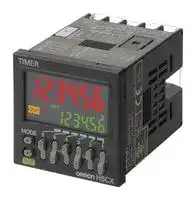
**Digital Timer H5CX**

CSM_H5CX_DS_E_3_1

Please read and understand this catalog before purchasing the products. Please consult your OMRON representative if you have any questions or comments. Refer to _Safety Precautions (Common)_ on page 47.

## **DIN 48** × **48-mm Multifunction Digital Timer/2-stage Digital Timer**

- Highly visible display with backlit negative transmissive LCD.

- Finger-safe terminals (screw terminal block models).

- Complies with IP66, NEMA4, and UL Type 4X (when using the Y92S-29 Waterproof Packing and Y92F-30 Flush Mounting Adapter).

## **H5CX Series**

**==> picture [62 x 11] intentionally omitted <==**

**----- Start of picture text -----**<br>
H5CX-A/-L<br>**----- End of picture text -----**<br>


**==> picture [81 x 72] intentionally omitted <==**

**----- Start of picture text -----**<br>
H5CX-B<br>Lamia<br>21<br>**----- End of picture text -----**<br>


**Multifunction Digital Timer with 4-digit display** H5CX-A (standard type) H5CX-L (economy type)

**2-stage Digital Timer with 6-digit display** H5CX-B

## **Contents**

## **Multifunction Digital Timer**

H5CX-A/-L........................................................ 2 **2-stage Digital Timer** H5CX-B............................................................ 35 **Common to All Models** Safety Precautions........................................... 50

**1**

**Multifunction Digital Timer H5CX-A/-L**

## **DIN 48** × **48-mm Multifunction Digital Timer with a Bright, Easy-to-view, Negative Transmissive LCD.**

- Programmable PV color to visually alert when output status changes (screw terminal block models).

- Intuitive setting enabled using DIP switch (H5CX-A/-A11 models) and ergonomic up/down digit keys.

- Twin timer in one body to meet a broader range of cyclic control application requirements as well as ON/OFF duty adjustable flicker mode.

- PNP/NPN switchable DC-voltage input (H5CX-A/-A11 models).

- Meet a variety of mounting requirements: Screw terminal block models, and pin-style terminal models.

- Six-language instruction manual.

## **Contents**

Model Number Structure .................................................................3 Ordering Information........................................................................3 Specifications ..................................................................................4 Connections.....................................................................................7 Nomenclature ..................................................................................11 Dimensions......................................................................................12 Operating Procedures .....................................................................17 Setting Procedure Guide...........................................................17 Operating Procedures (Timer Function)....................................18 Operating Procedures (Twin Timer Function)............................26 Operation in Timer/Twin Timer Selection Mode ........................31 Additional Information......................................................................32

**2**

**H5CX-A/-L**

## **Model Number Structure**

## ■ **Model Number Legend**

## **H5CX-** @@@@ **-** @

**1 2 3 4    5**

## **1. Type classifier**

   - A: Standard type

   - L: Economy type

**2. External connection** None: Screw terminals

   - 8: 8-pin socket

   - 11: 11-pin socket

## **3. Output type**

   - None: Contact output

   - S: Transistor output

**4. Supply voltage**

   - None: 100 to 240 VAC 50/60 Hz

   - D: 12 to 24 VDC/24 VAC 50/60 Hz

**5. Case color**

None: Black

- G: Light gray (Munsell 5Y7/1): Produced upon request.

## **Orderin Information g**

## ■ **List of Models**

|■**List of Models**|||||
|---|---|---|---|---|
|**Output type**|**Supply voltage**|**Models**|||
|||**Standard type**||**Economy type**|
|||**Screw terminals**|**11-pin socket**|**8-pin socket**|
|Contact output|100 to 240 VAC|H5CX-A|H5CX-A11|H5CX-L8|
||12 to 24 VDC/24 VAC|H5CX-AD|H5CX-A11D|H5CX-L8D|
|Transistor output|100 to 240 VAC|H5CX-AS|H5CX-A11S|H5CX-L8S|
||12 to 24 VDC/24 VAC|H5CX-ASD|H5CX-A11SD|H5CX-L8SD|


**Note:** Depending on the wiring, unwanted current from the AC power supply may occasionally burn out internal parts. H5CX-A/-L (except for H5CXA11/-A11S) models do not have a transformer. Therefore, the power supply and input circuit are not insulated. Refer to _Safety Precautions (H5CX-A/-L)_ on page 49 for wiring details. The power supply and input circuit for H5CX-A11/-A11S models have basic insulation.

## ■ **Accessories (Order Separately)**

|**Name**|**Name**|**Models**|
|---|---|---|
|Flush MountingAdapter (See note 1.)||Y92F-30|
|Waterproof Packing(See note 1.)||Y92S-29|
|Track Mounting/<br>Front Connecting Socket|8-pin|P2CF-08|
||8-pin, finger-safe type|P2CF-08-E|
||11-pin|P2CF-11|
||11-pin, finger-safe type|P2CF-11-E|
|Back Connecting Socket|8-pin|P3G-08|
||8-pin, finger-safe type|P3G-08 with Y92A-48G (See note 2.)|
||11-pin|P3GA-11|
||11-pin, finger-safe type|P3GA-11 with Y92A-48G (See note 2.)|
|Hard Cover||Y92A-48|
|Soft Cover||Y92A-48F1|
|Mounting Track|50 cm (l)×7.3 mm (t)|PFP-50N|
||1 m (l)×7.3 mm (t)|PFP-100N|
||1 m (l)×16 mm (t)|PFP-100N2|
|End Plate||PFP-M|
|Spacer||PFP-S|


**Note 1.** Supplied with H5CX-A@ models (except for H5CX-A11@ and H5CX-L8@ models).

**2.** Y92A-48G is a finger-safe terminal cover attached to the P3G-08 or P3GA-11 Socket.

**3**

**H5CX-A/-L**

## **S ecifications p**

## ■ **Ratings**

|■**Ratings**||||
|---|---|---|---|
|**Item**|**H5CX-A**@|**H5CX-A11**@|**H5CX-L8**@|
|Classification|Digital timer|||
|Rated supplyvoltage|100 to 240 VAC (50/60 Hz), 24 VAC (50/60 Hz)/12 to 24 VDC (permissible ripple: 20% (p-p) max.)|||
|Operatingvoltage range|85% to 110% rated supply voltage (12 to 24 VDC: 90% to 110%)|||
|Power consumption<br>(See note 1.)|Approx. 6.2 VA at 264 VAC<br>Approx. 5.1 VA at 26.4 VAC<br>Approx. 2.4 W at 12 VDC|||
|Mountingmethod|Flush mounting|Flush mounting, surface mounting, DIN track mounting||
|External connections|Screw terminals|11-pin socket|8-pin socket|
|Terminal screw tightening<br>torque|0.5 N·m max.|---||
|Display<br>(See note 2.)|7-segment, negative transmissive LCD;<br>Present value:<br>11.5-mm-high characters,<br>red or green (programmable)<br>Set value: 6-mm-high characters,green|7-segment, negative transmissive LCD<br>Present value:<br>11.5-mm-high characters, red<br>Set value: 6-mm-high characters,green||
|Digits|4 digits|||
|Time ranges|9.999 s (0.001-s unit), 99.99 s (0.01-s unit), 999.9 s (0.1-s unit), 9999 s (1-s unit), 99 min 59 s (1-s unit)<br>999.9 min (0.1-min unit), 9999 min (1-min unit), 99 h 59 min (1-min unit), 999.9 h (0.1-h unit), 9999 h (1-h unit)|||
|Timer mode|Elapsed time (Up), remainingtime (Down) (selectable)|||
|Input signals|Signal, reset,gate||Signal, reset|
|Input method|No-voltage input/voltage input (switchable)<br>No-voltage Input<br>ON impedance: 1 kΩmax. (Leakage current: 5 to 20 mA when 0Ω)<br>ON residual voltage: 3 V max.<br>OFF impedance: 100 kΩmin.<br>Voltage Input<br>High (logic) level: 4.5 to 30 VDC<br>Low (logic) level: 0 to 2 VDC<br>(Input resistance: approx. 4.7 kΩ)||No-voltage Input<br>ON impedance: 1 kΩmax. (Leak-<br>age current: 5 to 20 mA when 0Ω)<br>ON residual voltage: 3 V max.<br>OFF impedance: 100 kΩmin.|
|Signal, reset,gate|Minimum input signal width: 1 or 20 ms (selectable, same for all input)|||
|Reset system|Power resets (except for A-3, b-1, and F modes), external and manual reset|||
|Power reset|Minimum power-openingtime: 0.5 s (except for A-3, b-1, and F mode)|||
|Reset voltage|10% max. of rated supplyvoltage|||
|Sensor waitingtime|250 ms max. (Control output is turned OFF and no input is accepted duringsen||sor waitingtime.)|
|Output modes|A, A-1, A-2, A-3, b, b-1, d, E, F, Z, ton or toff|||
|One-shot output time|0.01 to 99.99 s|||
|Control output|SPDT contact output: 5 A at 250 VAC/30 VDC, resistive load (cosφ=1)<br>Minimum applied load: 10 mA at 5 VDC (failure level: P, reference value)<br>Transistor output: NPN open collector, 100 mA at 30 VDC max.<br>residual voltage: 1.5 VDC max. (Approx. 1 V)<br>Leakage current: 0.1 mA max.|||
||Output category according to EN60947-5-1 for Timers with Contact Outputs (AC-15; 250 V 3 A/AC-13; 250 V 5 A/<br>DC-13; 30 V 0.5 A)<br>Output category according to EN60947-5-2 for Timers with Transistor Outputs (DC-13; 30 V 100 mA)<br>NEMA B300 Pilot Duty, 1/4 HP 5-A resistive load at 120 VAC, 1/3 HP 5-A resistive load at 240 VAC|||
|Keyprotection|Yes|||
|Memorybackup|EEPROM (overwrites: 100,000 times min.) that can store data for 10years min.|||
|Ambient temperature|Operating:<br>−10 to 55°C (−10 to 50°C if timers are mounted side by side) (with no icing or condensation)<br>Storage:<br>−25 to 65°C (with no icingor condensation)|||
|Ambient humidity|25% to 85%|||
|Case color|Black (N1.5)|||
|Attachments|Waterproof packing,<br>flush mounting adapter,<br>label for DIP switch settings|Label for DIP switch settings|None|


**Note 1.** Inrush current will flow for a short time when the power supply is turned ON. Refer to _Inrush Current (Reference Values)_ on page 6.

**2.** The display is lit only when the power is ON.

**4**

**H5CX-A/-L**

## ■ **Characteristics**

|**Item**|**H5CX-A**@**/-A11**@**/-L8**@|
|---|---|
|Accuracy of operating time<br>and setting error (including<br>temperature and voltage in-<br>fluences) (See note 1.)|Power-ON start:±0.01%±50 ms max. Rated against set value<br>Signal start:±0.005%±30 ms max. Rated against set value<br>Signal start for transistor output model:±0.005%±3 ms max. (See note 2.)<br>If the set value is within the sensor waiting time at startup the control output of the H5CX will not turn ON until the<br>sensor waitingtime passes.|
|Insulation resistance|100 MΩmin. (at 500 VDC) between current-carrying terminal and exposed non-current-carrying metal parts, and<br>between non-continuous contacts|
|Dielectric strength|2,000 VAC, 50/60 Hz for 1 min between current-carrying metal parts and non-current-carrying metal parts<br>1,000 VAC (for H5CX-@SD), 50/60 Hz for 1 min between control output, power supply, and input circuit (2,000 VAC<br>for models other than H5CX-@SD)<br>1,000 VAC, 50/60 Hz for 1 min between non-continuous contacts|
|Impulse withstand voltage|3 kV (between power terminals) for 100 to 240 VAC, 1 kV for 24 VAC/12 to 24 VDC<br>4.5 kV (between current-carrying terminal and exposed non-current-carrying metal parts) for 100 to 240 VAC<br>1.5 kV for 24 VAC/12 to 24 VDC|
|Noise immunity|±1.5 kV (between power terminals) and±600 V (between input terminals), square-wave noise by noise simulator<br>(pulse width: 100 ns/1µs, 1-ns rise)|
|Static immunity|Destruction: 15 kV<br>Malfunction: 8 kV|
|Vibration resistance|Destruction: 10 to 55 Hz with 0.75-mm single amplitude each in three directions, 2 hours each<br>Malfunction: 10 to 55 Hz with 0.35-mm single amplitude each in three directions, 10 min each|
|Shock resistance|Destruction: 294 m/s2each in three directions<br>Malfunction: 196 m/s2each in three directions|
|Life expectancy|Mechanical: 10,000,000 operations min. (under no load at 18,000 operations/h)<br>Electrical:<br>100,000 operations min. (5 A at 250 VAC, resistive load at 1,800 operations/h)<br>See_Life-test Curve_on page 6.|
|Approved safety standards<br>(See notes 3 and 4.)|UL508/Listing, UL50 Type 4X for indoor use (enclosure rating), CSA C22.2 No. 14, conforms to EN61812-1 (Pollution<br>degree 2/overvoltage category III)<br>Conforms to VDE0106/P100 (finger protection).|
|EMC|(EMI)<br>EN61812-1<br>Emission Enclosure:<br>EN55011 Group 1 class A<br>Emission AC mains:<br>EN55011 Group 1 class A<br>(EMS)<br>EN61812-1<br>Immunity ESD:<br>EN61000-4-2:<br>6 kV contact discharge (level 2)<br>8 kV air discharge (level 3)<br>Immunity RF-interference:<br>EN61000-4-3:<br>10 V/m (Amplitude-modulated, 80 MHz to 1 GHz) (level 3);<br>10 V/m (Pulse-modulated, 900 MHz±5 MHz) (level 3)<br>Immunity Conducted<br>Disturbance:<br>EN61000-4-6:<br>10 V (0.15 to 80 MHz) (level 3)<br>Immunity Burst:<br>EN61000-4-4:<br>2 kV power-line (level 3);<br>1 kV I/O signal-line (level 4)<br>Immunity Surge:<br>EN61000-4-5:<br>1 kV line to lines (power and output lines) (level 3);<br>2 kV line to ground (power and output lines) (level 3)<br>ImmunityVoltage Dip/Interruption EN61000-4-11:<br>0.5 cycle, 100% (rated voltage)|
|Degree of protection|Panel surface: IP66 and NEMA4 (indoors), and UL Type 4X (indoors) (See note 4.)|
|Weight|H5CX-A@: Approx. 135g, H5CX-A11@/-L8@: Approx. 105g|


**Note 1.** The values are based on the set value.

**2.** The value is applied for a minimum pulse width of 1 ms.

**3.** To meet UL listing requirements with H5CX-L8@/-A11@ models, an OMRON P2CF-08-@ or P3G-08 Socket must be mounted on the Timer. Otherwise, H5CX-L8@/-A11@ models are considered to meet UL508 recognition requirements.

**4.** The Y92S-29 Waterproof Packing and Y92F-30 Flush Mounting Adapter are necessary to ensure IP66, NEMA4, and UL Type 4X waterproofing between the H5CX and installation panel.

**5**

**H5CX-A/-L**

## ■ **Life-test Curve (Reference Values)**

**==> picture [171 x 159] intentionally omitted <==**

**----- Start of picture text -----**<br>
1,000<br>500<br>100<br>30 VDC L/R=7 ms<br>50<br>250 VDC/30 VDC<br>cosφ=1<br>10<br>250 VAC cosφ=0.4<br>0 1 2 3 4 5<br>Load current (A)<br>4)10<br>×<br>Switching operations (<br>**----- End of picture text -----**<br>


Reference: A maximum current of 0.15 A can be switched at 125 VDC (cosφ=1) and a maximum current of 0.1 A can be switched if L/R is 7 ms. In both cases, a life of 100,000 operations can be expected. The minimum applicable load is 10 mA at 5 VDC (failure level: P).

## ■ **Inrush Current (Reference Values)**

|**Voltage**|**Applied voltage**|**Inrush current**<br>**(peak value)**|**Time**|
|---|---|---|---|
|100 to 240 VAC|264 VAC|5.3 A|0.4 ms|
|24 VAC/<br>12 to 24 VDC|26.4 VAC|6.4 A|1.4 ms|
||26.4 VDC|4.4 A|1.7 ms|


**6**

**H5CX-A/-L**

## **Connections**

## ■ **Block Diagram**

**==> picture [232 x 108] intentionally omitted <==**

**----- Start of picture text -----**<br>
(Basic insulation)<br>Output circuit Power supply<br>circuit<br>(Basic insulation) (See note.)<br>Display circuit<br>Input circuit Internal control<br>circuit<br>Key switch<br>circuit<br>**----- End of picture text -----**<br>


**Note:** Power circuit is not insulated from the input circuit, except for H5CX-A11/-A11S, which have basic insulation.

## ■ **I/O Functions**

|**Inputs**|**Start signal**|Stops timing in A-2 and A-3 (power ON delay) modes.<br>Starts timingin other modes.|
|---|---|---|
||**Reset**|Resets present value. (In elapsed time mode, the present value returns to 0; in remaining time<br>mode, the present value returns to the set value.)<br>Count inputs are not accepted and control output turns OFF while reset input is ON.<br>Reset indicator is lit while reset input is ON.|
||**Gate**|Inhibits timer operation. (The timer will be reset if the reset input turns ON while the gate input is<br>ON.)|
|**Outputs**|**Control output (OUT)**|Outputs take place according to designated operating mode when timer reaches corresponding set<br>value.|


**7**

**H5CX-A/-L**

## ■ **Terminal Arrangement**

Confirm that the power supply meets specifications before use.

## **H5CX-A/-AD**

**==> picture [102 x 130] intentionally omitted <==**

**----- Start of picture text -----**<br>
Input use 0 V<br>Unused<br>6 7 8 9 10<br>Unused Unused Unused<br>11 12 13<br>1 2 3 4 5<br>Contact output<br>(−) (+)<br>Reset Signal Gate<br>**----- End of picture text -----**<br>


The power supply and input circuit are not insulated. (See note 2.) Terminals 1 and 6 of the H5CX-AD are connected internally.

## **H5CX-A11/-A11D**

**==> picture [157 x 104] intentionally omitted <==**

**----- Start of picture text -----**<br>
Reset<br>Signal<br>Gate Internal circuit<br>5 6 7<br>Unused 4 8<br>0 V 3 9<br>2 1 11 10 Contact output<br>Unused<br>(−) (+)<br>**----- End of picture text -----**<br>


The power supply and input circuit of the H5CX-A11 have basic insulation. The power supply and input circuit of the H5CX-A11D are not insulated. (See note 2.) Terminals 2 and 3 of the H5CX-A11D are connected internally.

## **H5CX-L8/-L8D**

**==> picture [158 x 93] intentionally omitted <==**

**----- Start of picture text -----**<br>
Internal circuit<br>Signal<br>4 5<br>Reset<br>3 6<br>2 7 Contact output<br>1 8<br>0 V<br>(−) (+)<br>**----- End of picture text -----**<br>


The power supply and input circuit are not insulated. (See note 2.) Terminals 1 and 2 of the H5CX-L8D are connected internally.

## **H5CX-AS/-ASD**

**==> picture [102 x 131] intentionally omitted <==**

**----- Start of picture text -----**<br>
Input use 0 V<br>Unused<br>6 7 8 9 10<br>Unused Unused Unused<br>11 12 13<br>1 2 3 4 5<br>Transistor output<br>(−) (+)<br>Reset Signal Gate<br>**----- End of picture text -----**<br>


The power supply and input circuit are not insulated. (See note 2.)

Terminals 1 and 6 of the H5CX-ASD are connected internally.

## **H5CX-A11S/-A11SD**

**==> picture [163 x 105] intentionally omitted <==**

**----- Start of picture text -----**<br>
Reset<br>Signal<br>Gate Internal circuit<br>5 6 7<br>Unused 4 8<br>0 V 3 9<br>2 1 11 10 Transistor output<br>Unused<br>(−) (+)<br>**----- End of picture text -----**<br>


The power supply and input circuit of the H5CX-A11S have basic insulation. The power supply and input circuit of the H5CX-A11SD are not insulated. (See note 2.) Terminals 2 and 3 of the H5CX-A11SD are connected internally.

## **H5CX-L8S/-L8SD**

**==> picture [161 x 92] intentionally omitted <==**

**----- Start of picture text -----**<br>
Internal circuit<br>Signal  Unused<br>4 5<br>Reset<br>3 6<br>2 7 Transistor output<br>1 8<br>0 V<br>(−) (+)<br>**----- End of picture text -----**<br>


The power supply and input circuit are not insulated. (See note 2.) Terminals 1 and 2 of the H5CX-L8SD are connected internally.

- **Note 1.** Do not connect unused terminals as relay terminals.

   **2.** The power supply and input circuit are not insulated, so unwanted current from the AC power supply may burn out internal parts. Refer to _Safety Precautions (H5CX-A/-L)_ on page 49 for wiring details.

**8**

**H5CX-A/-L**

## ■ **Input Circuits**

## **Signal, Reset, and Gate Input**

**==> picture [146 x 71] intentionally omitted <==**

**----- Start of picture text -----**<br>
+14 V<br>1 kΩ<br>IN Internal circuit<br>**----- End of picture text -----**<br>


**Note:** When using no-voltage input (NPN input).

## ■ **Input Connections**

The inputs of the H5CX-A@/-A11@ are no-voltage (short-circuit or open) inputs or voltage inputs.

The input of the H5CX-L8@ is no-voltage input only.

**Note:** Power circuit is not insulated from the input circuit, except for H5CX-A11/-A11S, which have basic insulation. For wiring, refer to _Safety Precautions (H5CX-A/-L)_ on page 49 _._

## **No-voltage Inputs (NPN Inputs)**

**==> picture [506 x 159] intentionally omitted <==**

**----- Start of picture text -----**<br>
Open Collector Voltage Output Contact Input DC Two-wire Sensor<br>PC or sensor<br>Sensor<br>0 V 0 V 0 V 0 V<br>H5CX-A@ H5CX-A@ H5CX-A@ H5CX-A@<br>H5CX-A11@ H5CX-A11@ H5CX-A11@ H5CX-A11@<br>H5CX-L8@ H5CX-L8@ H5CX-L8@ H5CX-L8@<br>Operate with transistor ON Operate with transistor ON Operate with relay ON Operate with transistor ON<br>(Connection to NPN open  (Connection to a voltage output<br>collector output sensor) sensor)<br>Input Reset input Signal input Gate input Input Reset input Signal input Gate input Input Reset input Signal input Gate input Input Reset input Signal input Gate input<br>**----- End of picture text -----**<br>


## **No-voltage Input Signal Levels**

|No-contact input|Short-circuit level<br>Transistor ON<br>Residual voltage: 3 V max.<br>Impedance when ON: 1 kΩmax.<br>(the leakage current is about 12 mA when the<br>impedance is 0Ω)|
|---|---|
||Open level<br>Transistor OFF<br>Impedance when OFF: 100 kΩmin.|
|Contact input|Use contact which can adequately switch<br>5 mA at 10 V|


## **Applicable Two-wire Sensor**

Leakage current: 1.5 mA max. Switching capacity: 5 mA min. Residual voltage: 3.0 VDC max. Operating voltage: 10 VDC

**Note:** The DC voltage must be 30 VDC max.

**9**

**H5CX-A/-L**

## **Voltage Inputs (PNP Inputs)**

## **No-contact Input (NPN Transistor)**

(Connection to NPN open collector output sensor)

## **No-contact Input (PNP Transistor)**

(Connection to PNP open collector output sensor)

## **Contact Input**

**==> picture [398 x 109] intentionally omitted <==**

**----- Start of picture text -----**<br>
Sensor Sensor<br>0 V 0 V 0 V<br>H5CX-A@ H5CX-A@ H5CX-A@<br>H5CX-A11@ H5CX-A11@ H5CX-A11@<br>Operate with transistor OFF Operate with transistor ON Operate with relay ON<br>Input Reset input Signal input Gate input Input Reset input Signal input Gate input Input Reset input Signal input Gate input<br>**----- End of picture text -----**<br>


## **Voltage Input Signal Levels**

High level (Input ON): 4.5 to 30 VDC Low level (Input OFF): 0 to 2 VDC Input resistance: Approx. 4.7 kΩ **Note:** The DC voltage must be 30 VDC max.

**10**

**H5CX-A/-L**

## **Nomenclature**

**==> picture [495 x 264] intentionally omitted <==**

**----- Start of picture text -----**<br>
Indicator Operation Key<br> Reset Indicator (orange)  Mode Key<br>(Changes modes and setting items)<br> Key Protection Indicator (orange)<br>Reset Key<br> Control Output Indicator (orange) (Resets present value and output)<br> Present Value Up Keys 1 to 4<br>(red or green (programmable) for<br>H5CX-A models, red for H5CX-A11<br>Down Keys 1 to 4<br>/-L models)<br>Character height: 11.5 mm<br>Front View Front color: Black<br> Time Unit Display (Color is same as<br>present value and set value.): Switches<br>(If the time range is 0 min, 0 h, 0.0 h, or<br>0 h 0 min, this display flashes to  Key-protect Switch<br>indicate timing operation.) (Default setting) OFF    ON<br> Set Value (green)<br>Character height: 6 mm<br> Set Value 1, 2 Display<br>DIP Switch<br>Case color: Black 1 2 3 4 5 6 7 8<br>ON<br>OFF<br>**----- End of picture text -----**<br>


**Note 1:** All the pins are factory-set to OFF. **2:** There is no DIP switch on the H5CX-L8@.

**11**

**H5CX-A/-L**

## **Dimensions**

**Note:** All units are in millimeters unless otherwise indicated.

## ■ **Dimensions without Flush Mounting Adapter**

## **H5CX-A/-AS (Flush Mounting Models)**

**==> picture [390 x 95] intentionally omitted <==**

**----- Start of picture text -----**<br>
48x48 6 100<br>44.8x44.8<br>Note:  M3.5 terminal screw (effective length: 6 mm)<br>**----- End of picture text -----**<br>


## **H5CX-AD/-ASD (Flush Mounting Models)**

**==> picture [183 x 67] intentionally omitted <==**

**----- Start of picture text -----**<br>
48x48 6 64<br>44.8x44.8<br>**----- End of picture text -----**<br>


**Note:** M3.5 terminal screw (effective length: 6 mm)

## **H5CX-A11/-A11S (Flush Mounting/Surface Mounting Models)**

**==> picture [320 x 82] intentionally omitted <==**

**----- Start of picture text -----**<br>
14.4<br>48x48 6 72.5<br>44.8x44.8<br>**----- End of picture text -----**<br>


## **H5CX-A11D/-A11SD (Flush Mounting/Surface Mounting Models)**

**==> picture [309 x 80] intentionally omitted <==**

**----- Start of picture text -----**<br>
14.4<br>48x48 6 63.7<br>44.8x44.8<br>H5CX-A11D<br>**----- End of picture text -----**<br>


## **H5CX-L8** @ **(Flush Mounting/Surface Mounting Models)**

**==> picture [311 x 82] intentionally omitted <==**

**----- Start of picture text -----**<br>
14.3<br>48x48 6 63.7<br>44.8x44.8<br>**----- End of picture text -----**<br>


**12**

**H5CX-A/-L**

## ■ **Dimensions with Flush Mounting Adapter**

## **H5CX-A/-AS (Provided with Adapter and Waterproof Packing)**

**==> picture [314 x 124] intentionally omitted <==**

**----- Start of picture text -----**<br>
Panel Y92S-29 (provided) Waterproof Packing<br>Y92F-30 (provided)<br>Flush Mounting Adapter<br>+= 58 Don (51)<br>234 @ = i}<br>48 7.5 98.5<br>H5CX-AD/-ASD (Provided with Adapter and Waterproof Packing)<br>**----- End of picture text -----**<br>


**==> picture [399 x 268] intentionally omitted <==**

**----- Start of picture text -----**<br>
Y92S-29 (provided)  Panel<br>Waterproof Packing<br>Y92F-30 (provided)<br>Flush Mounting Adapter<br>58 (51) Panel Cutouts<br>Panel cutouts areas<br>shown below.<br>(according to DIN43700).<br>48 7.5 62.5 60 min.<br>45− [+0.6] 0<br>Y92S-29 (order separately)  Panel 45− [+0.6] 0<br>Waterproof Packing Y92F-30 (order separately)  T<br>Flush Mounting Adapter 60 min. 15 min.<br>P3GA-11<br>(order separately)<br>Rear Surface<br>Connection<br>Socket<br>7 58 [ oS (51) mi\g r(<br>Note 1.   The mounting panel thickness<br>should be 1 to 5 mm.<br>2.  To allow easier operability, it is<br>recommended that Adapters are<br>48 7.5 98.7 mounted so that the gap between<br>sides with hooks is at least 15 mm.<br>3.  It is possible to mount timers side<br>by side, but only in the direction<br>without the hooks.<br>**----- End of picture text -----**<br>


## **H5CX-A11/-A11S  (Adapter and Waterproof Packing Ordered Separately)**

## **H5CX-A11D/-A11SD (Adapter and Waterproof Packing Ordered Separately)**

**==> picture [261 x 102] intentionally omitted <==**

**----- Start of picture text -----**<br>
Y92S-29 (order separately)  Panel<br>Waterproof Packing Y92F-30 (order separately)<br>Flush Mounting Adapter<br>eT \6 L<br>P3GA-11<br>(order separately)<br>Rear Surface<br>58 (51) Connection<br>Socket<br>48 7.5 89.9<br>**----- End of picture text -----**<br>


n side by side mounting A − +1 A = (48n 2.5) 0 With Y92A-48F1 attached. − − A = {48n 2.5 + (n 1) x 4} 0 With Y92A-48 attached. A = (51n−5.5) +10 +1

## **H5CX-L8** @ **(Adapter and Waterproof Packing Ordered Separately)**

**==> picture [256 x 101] intentionally omitted <==**

**----- Start of picture text -----**<br>
Y92S-29 (order separately)  Panel<br>Waterproof Packing) Y92F-30 (order separately)<br>Flush Mounting Adapter<br>P3G-08<br>(order separately)<br>Rear Surface<br>Connection<br>Socket<br>58 (51)<br>| A , va<br>48 7.5 84.8<br>**----- End of picture text -----**<br>


**13**

**H5CX-A/-L**

## ■ **Dimensions with Front Connecting Socket**

**==> picture [284 x 75] intentionally omitted <==**

**----- Start of picture text -----**<br>
H5CX- H5CX-<br>H5CX-<br>A11/ A11D/<br>112 -A11S 109.7 103.2 -A11SD 100.9 92.3 L8@ 90<br>P2CF-11-@ P2CF-11-@ P2CF-08-@<br>**----- End of picture text -----**<br>


**Note:** These dimensions vary with the kind of DIN track (reference value).

## ■ **Accessories (Order Separately)**

**Note:** All units are in millimeters unless otherwise indicated.

## **Track Mounting/Front Connecting Socket**

**==> picture [247 x 103] intentionally omitted <==**

**----- Start of picture text -----**<br>
P2CF-08 Eight, M3.5 x 7.5 sems 7.8 3 4.5<br>maetiae oH<br>wm<br>hAcn one |<br>70 max. 35.4<br>Two, 4.5 dia.<br>holes<br>ne ay See ( o<br>4<br>50 max.<br>a<br>20.3 max.<br>**----- End of picture text -----**<br>


## **P2CF-08-E (Finger Safe Terminal Type) Conforming to VDE0106/P100**

**==> picture [176 x 112] intentionally omitted <==**

**----- Start of picture text -----**<br>
Eight,<br>M3.5 x 7.5 sems 5 4.5<br>7.8<br>3<br>70 max. 1.3 35.4<br>Two, 4.5 dia.  e e<br>holes<br>4<br>40±0.2 19<br>50 max. 20.3<br>21.5 max.<br>**----- End of picture text -----**<br>


**Terminal Arrangement/ Internal Connections (Top View) Surface Mounting Holes** 6R5 R403 Two, 4.5 dia. or two, M4 40±0.2 i ~~i~~

**14**

**H5CX-A/-L**

## **Track Mounting/Front Connecting Socket**

## **P2CF-11**

**==> picture [362 x 423] intentionally omitted <==**

**----- Start of picture text -----**<br>
Eleven,  3 4.5<br>M3.5 x 7.5 sems 7.8<br>Rn Uy Re _<br>eK | 70 max. CONS +E 35.4 Terminal Arrangement/ Internal Connections Internal Connections<br>Two, 4.5 dia.  (Top View)<br>holes<br>YT sy C\S|| Z cee n<br>4<br>50 max.<br>31.2 max.<br>| WZ oe O A<br>a<br>P2CF-11-E (Finger Safe Terminal Type) 9 3<br>Conforming to VDE0106/P100 0 @OO@<br>Eleven,<br>M3.5 x 7.5 sems 7.8 5 4.5<br>3<br>Po ee 1.2 Lb T<br>70 max. 35.4<br>ae fe ay/7 BeOaIey 5<br>Two, 4.5 dia.<br>holes<br>4<br>40±0.2 3 0<br>50 max.<br>31.2 max.<br>Back Connecting Socket Terminal Arrangement/<br>P3G-08 27 dia. Internal Connections<br>a (Bottom View)<br>hes3) 9 45 | EeSo | ! 150<br>a Sore<br>45 4.9 17<br>+ (4 it | YOO G<br>P3GA-11 Terminal Arrangement/<br>27 dia. Internal Connections<br>C7 (Bottom View)<br>45 25.6<br>(UE A)<br>( J d es<br>iin 45 4.5 TEL 6.2 a D<br>16.3<br>**----- End of picture text -----**<br>


**==> picture [197 x 67] intentionally omitted <==**

**----- Start of picture text -----**<br>
Terminal Arrangement/ Internal Connections Internal Connections<br>(Top View) Surface Mounting Holes<br>Two, 4.5 dia. or two, M4<br>A fo—-¢ 40±0.2<br>**----- End of picture text -----**<br>


**Finger Safe Terminal Cover Conforming to VDE0106/P100**

## **Y92A-48G**

**(Attachment for P3G-08/P3GA-11 Socket)**

**==> picture [147 x 120] intentionally omitted <==**

**----- Start of picture text -----**<br>
Twelve, 6.4 dia. holes<br>1S OO OF tI |<br>34 47.7 x 47.7 48 x 48<br>Ses! ac<br>OO 019.01O L<br>16.5<br>—t 24.6 27.6<br>ana|<br>— 47.4<br>**----- End of picture text -----**<br>


**15**

**H5CX-A/-L**

**Hard Cover Y92A-48**

**Soft Cover Y92A-48F1**

- **Note: 1.** Depending on the operating environment, the condition of resin products may deteriorate, and may shrink or become harder. Therefore, it is recommended that resin products are replaced regularly.

   **2.** The H5CX’s panel surface is water-resistive (conforming to IP66) and so even if drops of water penetrate the gaps between the keys, there will be no adverse effect on internal circuits. If, however, there is a possibility of oil being present on the operator’s hands, use the Soft Cover. The Soft Cover ensures protection equivalent to IP54 against oil. Do not, however, use the H5CX in locations where it would come in direct contact with oil.

**Flush Mounting Adapter (provided with models with H5CX-A/AD/AS/ASD) Y92F-30**

**Waterproof Packing (provided with models with H5CX-A/AD/AS/ASD) Y92S-29**

**Note:** Order the Flush Mounting Adapter separately if it is lost or damaged.

**Note:** Use Waterproof Packing to provide a level of water protection that complies with NEMA4, UL Type 4X, or IP66 standards. Order the Waterproof Packing separately if it is lost or damaged. Depending on the operating environment, the Waterproof Packing may deteriorate, contract, or harden and so regular replacement is recommended.

**==> picture [471 x 152] intentionally omitted <==**

**----- Start of picture text -----**<br>
Mounting Track<br>PFP-100N, PFP-50N PFP-100N2<br>a<_ ——————<br>16<br>7.3±0.15<br>4.5<br>4.5<br>35±0.3 27±0.15 35±0.3 27 24 29.2<br>15 25 25 25 25 * 15 25 25 25 25 15 1 1.5<br>oe 10 1,000 (500) 10 1 10 1,000 10 Tah<br>(See note.)<br>Note:  The values shown in parentheses are for the PFP-50N.<br>**----- End of picture text -----**<br>


**==> picture [443 x 117] intentionally omitted <==**

**----- Start of picture text -----**<br>
End Plate Spacer<br>PFP-M PFP-S<br>16<br>10 5 12<br>6.2<br>1.8<br>1<br>50 35.5 35.3 34.8<br>1.8 44.3<br>11.5 1.3<br>10 M4 x 8<br>pan head screw 4.8 16.5<br>**----- End of picture text -----**<br>


**16**

**H5CX-A/-L**

## **O eratin Procedures p g**

## ■ **Setting Procedure Guide**

## **Settings for Timer Operation**

Use the following settings for all models except the H5CX-L8@. Refer to page 19 for the H5CX-L8@.

**==> picture [434 x 190] intentionally omitted <==**

**----- Start of picture text -----**<br>
When Using Basic Functions Only<br>Basic Functions The settings can be performed easily with the DIP switch. ➡For details on the setting methods, refer to page 18.<br>•  Time range (0.001 s to 999.9 h,<br>except 9999 h and 9999min) 1 2 3 4 5 6 7 8<br>•  Output mode (A, A-2, E, F) ON<br>•  Timer mode (UP/DOWN)<br>•  Input signal width (20 ms/1 ms) OFF<br>When Using Other Time Ranges  When Using More Detailed Setting Items<br>(9999 h, 9999 min) and Output  (Output Time, NPN/PNP Input Mode,<br>Modes (A-1, A-3, b, b-1, d, and Z) Display Color, Key Protect Level)<br>All the functions can be set with the operation keys.  Setting for items other than the basic functions can be<br>➡For details on the setting methods, refer to page 19. performed with the operation keys.<br>➡For details on the setting methods, refer to page 19.<br>**----- End of picture text -----**<br>


**Note:** At the time of delivery, the H5CX is set for timer operation.

## **Settings for Twin Timer Operation**

Use the following settings for all models except the H5CX-L8@. Refer to page 27 for the H5CX-L8@.

**==> picture [434 x 190] intentionally omitted <==**

**----- Start of picture text -----**<br>
When Using Basic Functions Only<br>Basic Functions The settings can be performed easily with the DIP switch. ➡For details on the setting methods, refer to page 26.<br>•  Time range (0.01 s to 99 min 59 s)<br>•  ON/OFF start mode 1 2 3 4 5 6 7 8<br> (flicker OFF start/flicker ON start) ON<br>•  Timer mode (UP/DOWN)<br>•  Input signal width (20 ms/1 ms) OFF<br>When Using Other Time Ranges  When Using More Detailed Setting Items<br>(999.9 min, 9999 min, 99 h 59 min,  (NPN/PNP Input Mode, Display Color, Key<br>999.9 h, 9999 h, 9.999 s) Protect Level)<br>All the functions can be set with the operation keys.  Setting for items other than the basic functions can be<br>➡For details on the setting methods, refer to page 27. performed with the operation keys.<br>➡For details on the setting methods, refer to page 27.<br>**----- End of picture text -----**<br>


**Note:** At the time of delivery, the H5CX is set for timer operation.

**17**

**H5CX-A/-L**

## ■ **Operating Procedures (Timer Function)**

## **Settings for Basic Functions**

## **Settings for basic functions can be performed with just the DIP switch.**

||1<br>2<br>3<br>4<br>5<br>6<br>7<br>8<br>OFF<br>ON<br>Be sure to set pin 1 to ON when using the DIP switch.|1<br>2<br>3<br>4<br>5<br>6<br>7<br>8<br>OFF<br>ON<br>Be sure to set pin 1 to ON when using the DIP switch.|1<br>2<br>3<br>4<br>5<br>6<br>7<br>8<br>OFF<br>ON<br>Be sure to set pin 1 to ON when using the DIP switch.|1<br>2<br>3<br>4<br>5<br>6<br>7<br>8<br>OFF<br>ON<br>Be sure to set pin 1 to ON when using the DIP switch.|1<br>2<br>3<br>4<br>5<br>6<br>7<br>8<br>OFF<br>ON<br>Be sure to set pin 1 to ON when using the DIP switch.|1<br>2<br>3<br>4<br>5<br>6<br>7<br>8<br>OFF<br>ON<br>Be sure to set pin 1 to ON when using the DIP switch.|1<br>2<br>3<br>4<br>5<br>6<br>7<br>8<br>OFF<br>ON<br>Be sure to set pin 1 to ON when using the DIP switch.|1<br>2<br>3<br>4<br>5<br>6<br>7<br>8<br>OFF<br>ON<br>Be sure to set pin 1 to ON when using the DIP switch.|1<br>2<br>3<br>4<br>5<br>6<br>7<br>8<br>OFF<br>ON<br>Be sure to set pin 1 to ON when using the DIP switch.|||||
|---|---|---|---|---|---|---|---|---|---|---|---|---|---|
|||||||||||||||
||All the pins are factory-set to OFF.<br>**Item**<br>**OFF**<br>**ON**<br>DIP switch set-<br>tings enable/<br>disable<br>Disabled<br>Enabled<br>Time range<br>Refer to the table on the right.<br>Output mode<br>Refer to the table on the right.<br>Timer mode<br>Elapsed time<br>(UP)<br>Remaining time<br>(DOWN)<br>Input signal<br>width<br>20 ms<br>1 ms|||||||||||||
|||**Item**|**OFF**|**ON**|||**Pin 2**|**Pin 3**|||**Pin 4**||**Time range**|
|1|<br> <br>|DIP switch<br>tings enabl<br>disable|set-<br>e/<br>Disabled|Enabled|||ON|ON|||ON||0.001 s to 9.999 s|
||||||||OFF|OFF|||OFF||0.01 s to 99.99 s|
||||||||ON|OFF|||OFF||0.1 s to 999.9 s|
|2||Time range<br>|<br>Refer to the table on the right.<br> <br>|||||||||||
||||||||OFF|ON|||OFF||1 s to 9999 s|
|3||||||||||||||
||||||||ON|ON|||OFF||0 min 01 s to 99 min<br>59 s|
|4||||||||||||||
|5||Output mo|de<br>Refer to the table on the right.||||OFF|OFF|||ON||0.1 min to<br>999.9 min|
|6||||||||||||||
|7||Timer mod|e<br>Elapsed time<br>(UP)|Remaining time<br>(DOWN)|||ON|OFF|||ON||0 h 01 min to<br>99 h 59 min|
|8|<br>|Input signa<br>width|l<br>20 ms|1 ms|||OFF|ON|||ON||0.1 h to 999.9 h|
|||||||||||||||
|**Note:**||||||||||||||
||||||||**Pin 5**||**Pin 6**|||**Output mode**||
||||||||OFF||OFF|||A mode (signal ON delay<br>(I): power reset operation)||
||||||||ON||OFF|||A-2 mode: (power ON de-<br>lay (I): power reset opera-<br>tion)||
|**Easy Confirmation of Switch Settings Using Indicators**<br>The ON/OFF status of the DIP switch pins can be<br>confirmed using the front display. For details, refer to page 31.||||||||||||||
||||||||OFF||ON|||E mode (interval: power<br>reset operation)||
||||||||ON||ON|||F mode (accumulative:<br>power hold operation)||


**Note 1.** Be sure to set pin 1 of the DIP switch to ON. If it is set to OFF, the DIP switch settings will not be enabled.

**2.** Changes to DIP switch settings are enabled when the power is turned ON. (Perform DIP switch settings while the power is OFF.)

**3.** There is no DIP switch on the H5CX-L8@. For details on the setting methods, refer to page 19.

**4.** When using time ranges or output modes that cannot be set with the DIP switch, all of the settings have to be made using the operation keys. For details on the setting methods, refer to page 19.

## **Detailed Settings**

After making DIP switch settings for basic functions, detailed settings (see note) can be added using the operation keys. For details, refer to page 19.

**Note** : Output time, NPN/PNP input mode, display color, key protect level.

**18**

**H5CX-A/-L**

## **Settings for Advanced Functions**

## **Settings that cannot be performed with the DIP switch are performed with the operation keys.**

**==> picture [485 x 627] intentionally omitted <==**

**----- Start of picture text -----**<br>
|||||||||||
|---|---|---|---|---|---|---|---|---|---|
|Power ON|
|For details on operations in run mode, refer to page 21.|
|Note 1.|If the mode is switched to the function setting mode during operation,|
|operation will continue.|
|2.|Changes made to settings in function setting mode are enabled for the|
|first time when the mode is changed to run mode. Also, when settings|
|are changed, the timer is reset (time initialized and output turned OFF).|
|See note 1.|See note 2.|
|The characters displayed in reverse video are the default settings.|
|3 s min.|3 s min.|When performing settings with operation keys only, set pin1 of the|
|DIP switch to OFF (factory setting). If pin 1 of the DIP switch is set|
|to ON, the setting items indicated in|will not be displayed.|
|Set the time range using the                 keys.|
|Time range|
|s|s|s|......|h|s|
|For details, refer to|Time Range List|below.|
|Set the timer mode using the                 keys.|
|Timer mode|
|(Elapsed|(Remaining|
|time)|time)|
|Output mode|Set the output mode using the                 keys.|
|(A)|(A-1)|(A-2)|(A-3)|(b)|(b-1)|(d)|(E)|(F)|(Z)|
|Set each digit for the output time using the corresponding                keys.|
|Output time|
|: Output hold/0.01 to 99.99 s|Time Range List|
|(If the output time is set to 0.00,              is displayed.)|Display|Set Value|
|Displayed for modes A, A-1, A-2, A-3, b, and b-1 only.|
|Input signal|Set the input signal width using the                 keys.|0.01 s to 99.99 s (default setting)|
|width|
|0.1 s to 999.9 s|
|(20 ms)|(1 ms)|
|1 s to 9999 s|
|NPN/PNP|Set the NPN/PNP input mode using the                keys.|0 min 01 s to 99 min 59 s|
|input mode|
|(NPN input)|(PNP input)|0.1 min to 999.9 min|
|Only displayed for H5CX-A@ and H5CX-A11@ models.|
|1 min to 9999 min|
|Display color|Set the display color using the                keys.|
|0 h 01 min to 99 h 59 min|
|(Red)|(Green)|Red-green|Green-red|
|0.1 h to 999.9 h|
|Displayed for terminal-block models (H5CX-A@) only.|
|Key protect|Set the key protect level using the                keys.|1 h to 9999 h|
|level|
|0.001 s to 9.999 s|
|(KP-1)|(KP-2)|(KP-3)|(KP-4)|(KP-5)|

**----- End of picture text -----**<br>


**19**

**H5CX-A/-L**

## **Explanation of Functions**

## **Time Range (** timr **) (Setting possible using DIP switch.)**

Set the range to be timed in the range 0.000 s to 9,999 h. Settings of type ---- h (9,999 h) and ---- min (9,999 min) cannot, however, be made with the DIP switch. Use the operation keys if these settings are required.

## **Timer Mode (** timm **) (Setting possible using DIP switch.)**

Set either the elapsed time (UP) or remaining time (DOWN) mode.

## **Output Mode (** outm **) (Setting possible using DIP switch.)**

Set the output mode. The possible settings are A, A-1, A-2, A-3, b, b- 1, d, E, F, and Z. Only output modes A, A-2, E, and F can be set using the DIP switch. Use the operation keys if a different setting is required. (For details on output mode operation, refer to _Timing Charts_ on page 22.)

## **Output Time (** otim **)**

When using one-shot output, set the output time for one-shot output (0.01 to 99.99 s). One-shot output can be used only if the selected output mode is A, A-1, A-2, b, or b-1. If the output time is set to 0.00, hold is displayed, and the output is held.

## **Input Signal Width (** iflt **) (Setting possible using DIP switch.)**

Set the minimum signal input width (20 ms or 1 ms) for signal, reset, and gate inputs. The same setting is used for all external inputs (signal, reset, and gate inputs). If contacts are used for the input signal, set the input signal width to 20 ms. Processing to eliminate chattering is performed for this setting.

## **NPN/PNP Input Mode (** imod **)**

Select either NPN input (no-voltage input) or PNP input (voltage input) as the input format. The same setting is used for all external inputs. For details on input connections, refer to _Input Connections_ on page 9.

## **Display Color (** colr **)**

Set the color used for the present value.

||**Output OFF**|**Output ON**|
|---|---|---|
|red|Red (fixed)||
|grn|Green (fixed)||
|r-g|Red|Green|
|g-r|Green|Red|


## **Key Protect Level (** kypt **)**

Set the key protect level.

When the key-protect switch is set to ON, it is possible to prevent setting errors by prohibiting the use of certain operation keys by specifying the key protect level (KP-1 to KP-5). The key protect indicator is lit while the key-protect switch is set to ON.

**==> picture [218 x 103] intentionally omitted <==**

**----- Start of picture text -----**<br>
(See note) OFF ON<br>Note:  Factory-set to OFF<br>Key protect indicator<br>**----- End of picture text -----**<br>


|**Level**<br>|||**Meaning**<br>|**Meaning**<br>|**Details**|**Details**|**Details**|**Details**|
|---|---|---|---|---|---|---|---|---|
||||||**Changing mode**<br>**(See note.)**<br>|**Switching display**<br>**during operation**<br>|**Reset key**<br>|**Up/down key**<br>|
|KP-1<br>(default setting)|||||No|Yes|Yes|Yes|
|KP-2|||||No|Yes|No|Yes|
|KP-3|||||No|Yes|Yes|No|
|KP-4|||||No|Yes|No|No|
|KP-5|||||No|No|No|No|
|**Note:**Changing mode to timer/twin timer selection mode (<br>+<br>1 s min.) or function setting mode (<br>3 s min.).<br>**MODE**<br>1<br>**MODE**|||||||||


**20**

**H5CX-A/-L**

## **Operation in Run Mode**

**When Output Mode Is Not Z**

**==> picture [67 x 39] intentionally omitted <==**

**==> picture [247 x 30] intentionally omitted <==**

**----- Start of picture text -----**<br>
Set each digit for the set value using the corresponding                   keys.<br>Present value<br>Set value<br>**----- End of picture text -----**<br>


## **When Output Mode Z Is Selected**

**==> picture [97 x 115] intentionally omitted <==**

**==> picture [264 x 117] intentionally omitted <==**

**----- Start of picture text -----**<br>
Set each digit for the ON duty ratio using the corresponding                   keys.<br>Present value (The                  keys for the 4th digit cannot be used.)<br>ON duty ratio<br>Set each digit for the cycle time using the corresponding                  keys.<br>Present value<br>Cycle time<br>**----- End of picture text -----**<br>


## **Present Value and Set Value**

These items are displayed when the power is turned ON. The present value is displayed in the main display and the set value is displayed in the sub-display. The values displayed will be determined by the settings made for the time range and the timer mode in function setting mode.

## **Present Value and ON Duty Ratio (Output Mode = Z)**

The present value is displayed in the main display and the ON duty ratio is displayed in the sub-display. “SET1” lights at the same time.

Set the ON duty ratio used in ON/OFF-duty adjustable flicker mode (Z) as a percentage.

If a cycle time is set, cyclic control can be performed in ON/OFF-duty adjustable flicker mode simply by changing the ON duty ratio.

ON time = Cycle time ×[ON duty ratio (%)]

100

The output accuracy will vary with the time range, even if the ON duty ratio setting is the same. Therefore, if fine output time adjustment is required, it is recommended that the time range for the cycle time is set as small as possible.

## **Present Value and Cycle Time (Output Mode = Z)**

The present value is displayed in the main display and the cycle time is displayed in the sub-display. “SET2” lights at the same time. Set the cycle time used in ON/OFF-duty adjustable flicker mode (Z).

**==> picture [241 x 160] intentionally omitted <==**

**----- Start of picture text -----**<br>
Elapsed cycle time<br>ON duty set as a percentage<br>Up/down keys used for analog<br>adjustment of the ON duty<br>Cycle time<br>Close Open<br>ON duty (%)<br>Output control<br>Opening/closing valve Fully closed↔Fully open<br>ON duty 0%↔100%<br>**----- End of picture text -----**<br>


## Examples:

**1.** If the cycle time is 20 s, the ON duty ratio is 31%, and the time range is 1 s to 9999 s, the ON time is given by the following:

   - 20 (s) × 31 (%) = 6.2 (s) → Rounded off to the nearest integer 100

   - (because of the time range setting) → ON time = 6 s

**2.** If the cycle time is 20.00 s, the ON duty ratio is 31%, and the time range is 0.01 s to 99.99 s, the ON time is given by the following:

20.00 (s) × 31 (%) = 6.200 (s) → Rounded off to 2 decimal places 100

- (because of the time range setting) → ON time = 6.20 s

**21**

**H5CX-A/-L**

## **Timing Charts**

## **Timer Operation**

The gate input is not included in the H5CX-L8@ models.

**==> picture [497 x 632] intentionally omitted <==**

**----- Start of picture text -----**<br>
One-shot output<br>t<br>Sustained output Either one-shot output or sustained output can be selected.<br>Output mode A: Signal ON delay 1 (Timer resets when power comes ON.)<br>Power Timing starts when the start signal goes ON.<br>i ot rot While the start signal is ON, the timer starts when the<br>ot rotrot power comes ON or when the reset input goes OFF.<br>Start signal rot The control output is controlled using a sustained or<br>1 —— one-shot time period.<br>Gate 'f1 ' ' iItotot1 rot'hotti !I<br>1 fl try 1 1 1 ! iat Basic Operation<br>Reset 1 f rititt Pootrt<br>1 t 1 Pop op tg f ot tt t Power<br>Control output A Prog tte g y robot 7] ** =<br>Timing  Set valueUP re! 4 SBPion btn 4 pePoparot it1 | Start signal input Timing<br>diagram 0 ' ! \ Por py 1 H rorr Output ee<br>Set value <----t---] it<br>DOWN 0 > tH | NOS ™“Cha elnieiera<alaiant' ~ rotrttet f~ee rid1 * **  [Output is instantaneous when setting is 0.][Start signal input is disabled during timing.]<br>Output mode A-1: Signal ON delay 2 (Timer resets when power comes ON.)<br>Power Timing starts when the start signal goes ON, and is<br>it rt reset when the start signal goes OFF.<br>Lt Lt While the start signal is ON, the timer starts when the<br>Start signal rt power comes ON or when the reset input goes OFF.<br>i t I itVy i t —trt The control output is controlled using a sustained or<br>H I ' it f 1 14 one-shot time period.<br>Gate } bor i<br>Basic Operation<br>Reset t — rer ttn——ft : I 1t Power ————<br>Timing diagramControl outputSet valueUP 0 —an iZ|' Fi ro—poo reyA=rr———14 |it771i: tZ|it4i Start signal inputOutput oo Timing Go<br>Set value ! uieieiel I ete ' e = ee eeoptee No ' ! SOs‘oa *  [Output is instantaneous when setting is 0.]<br>DOWN 1 '<br>0<br>Output mode A-2: Power ON delay 1 (Timer resets when power comes ON.)<br>Power Timing starts when the reset input goes OFF.<br>1 rt rot The start signal disables the timing function (i.e., same<br>II odod rotrot function as the gate input).<br>Start signal ' rot rot The control output is controlled using a sustained or<br>1 mt 1 I one-shot time period.<br>Gate f i rot ' rotI<br>I : + + — Basic Operation<br>Reset I ri t bo ioporro 4 i I!I !vt! ] !'! Lotio Power Timing GY seeeseeresaee<br>Control output i 1 iee 1 fiy f' ' Output 4<br>Timing  Set valueUP -----}----yIH eeenn1 nee ees eera a en ' trota *  [Output is instantaneous when setting is 0.]<br>diagram 0 1 1 1 tt 1! 1 1<br>Set value<br>DOWN 1! No! } t ret1 i)<br>0<br>Output mode A-3: Power ON delay 2 (Timer does not reset when power comes ON.)<br>Power Timing starts when the reset input goes OFF.<br>t rot rt ro The start signal disables the timing function (i.e.,<br>1! rot1 1 itre io1 i) same function as the gate input).<br>Start signal I rot rt rot The control output is controlled using a sustained or<br>rI it —rot Irt Ttrot one-shot time period.<br>1 ' ' 1 ! iat 1 1<br>Gate ! ' ' 1 ! re I I Basic Operation<br>f —! rt rt To :<br>Control outputReset 1!I1 Z t i1 'ee''porp'ty 1og itbh I1yg11 Y t rtPre 1m !'! AI11 It7 t OutputPower TimingSustained 49Gapopcnncne ce<br>I ee rr ot<br>Timing  Set valueUP a 1Darr capa 1 D i D as i fee ! cant' ra  ay hao t * Output is instantaneous when setting is 0.<br>diagram 0 1 ' 1 ! ' ty i} an 1 1 ! ree ' 14 1<br>Set value a<br>DOWN H1 oa boro ! oadre hit1y 1<br>0<br>**----- End of picture text -----**<br>


**22**

**H5CX-A/-L**

.

**==> picture [510 x 644] intentionally omitted <==**

**----- Start of picture text -----**<br>
OOOO Output mode b: Repeat cycle 1 (Timer resets when power comes ON.) “<br>Timing starts when the start signal goes ON.<br>Sustained  Power<br>_—innEEE The status of the control output is reversed when time<br>Output is up (OFF at start).<br>While the start signal is ON, the timer starts when the<br>Start signal power comes ON or when the reset input goes OFF.<br>Basic Operation<br>Gate 7 : : [| 7 | 3 3 7 Power CC<br>Reset<br>! Bi m<br>Start signal **<br>Control output input Timing Timing Timing Timing<br>Set value Output<br>Timing diagram UP 0 *   [Normal output operation will not be possible if the ]<br>Set value set time is too short.<br>DOWN Set the value to at least 100 ms (contact output<br>0 type).<br>**  [Start signal input is disabled during timing.]<br>Timing starts when the start signal goes ON.<br>One-shot  Power<br>Output _—EEee The control output is turned ON when time is up.While the start signal is ON, the timer starts when the<br>power comes ON or when the reset input goes OFF.<br>Start signal<br>Basic Operation<br>Gate<br>Power<br>Reset Start signal **<br>t t input Timing Timing Timing Timing<br>Control output<br>Output<br>Set value<br>Timing  UP<br>diagram 0 *  set time is too short. [Normal output operation will not be possible if the ]<br>Set value Set the value to at least 100 ms (contact output<br>DOWN type).<br>0 **  [Start signal input is disabled during timing.]<br>OOOOOOOOOOCOSOOOOSOSCSC“S*Ss“‘“‘*sts~*Y Output mode b-1: Repeat cycle 2 (Timer does not reset when power comes ON.)<br>Sustained  Power Timing starts when the start signal goes ON.<br>Ex Oe The status of the control output is reversed when time<br>Output is up (OFF at start).<br>While the start signal is ON, the timer starts when the<br>Start signal<br>power comes ON or when the reset input goes OFF.<br>Gate Basic Operation<br>Power<br>Reset Timing Sustained Timing<br>Start signal **<br>Control output input<br>Set value m = i on le Output ee<br>Timing diagram UP 0 *  [Normal output operation will not be possible if the ]<br>Set value set time is too short.<br>DOWN 0 type).Set the value to at least 100 ms (contact output<br>**  [Start signal input is disabled during timing.]<br>One-shot  Timing starts when the start signal goes ON.<br>Output Power The control output comes ON when time is up.<br>_ HSS), SSS, SS SS While the start signal is ON, the timer starts when<br>power comes ON or when the reset input goes OFF.<br>Start signal<br>Basic Operation<br>Gate<br>Power<br>Reset Timing Sustained Timing<br>t t t t t Start signal **<br>Control output input<br>Set value Output<br>Timing diagram Set valueUP 0 *   [Normal output operation will not be possible if the ]<br>DOWN set time is too short.<br>0 Set the value to at least 100 ms (contact output<br>type).<br>**  [Start signal input is disabled during timing.]<br>**----- End of picture text -----**<br>


**23**

**H5CX-A/-L**

**==> picture [510 x 617] intentionally omitted <==**

**----- Start of picture text -----**<br>
[OO Output mode d: Signal OFF delay (Timer resets when power comes ON.) OO<br>Power The control output is ON when the start signal is ON<br>_nnn)[| fa (except when the power is OFF or the reset is ON).<br>The timer is reset when the time is up.<br>Start signal Basic Operation<br>Gate<br>Power<br>Reset Start signal **<br>input Timing<br>Control output<br>Output<br>Set value<br>Timing diagram UP 0 *  setting is 0. [Output functions only during start signal input when ]<br>Set value **  [Start signal input is enabled during timing.]<br>DOWN<br>0<br>POO Output mode E: Interval (Timer resets when power comes ON.)<br>Power _ ESS)ESS SS Timing starts when the start signal comes ON.The control output is reset when time is up.<br>Start signal While the start signal is ON, the timer starts when power comes ON or when the reset input goes OFF.<br>Gate Basic Operation<br>Power<br>Reset<br>Control output Start signal **<br>input<br>Set value Timing<br>Timing diagram UP 0 Output ——  ae<br>Set value<br>DOWN 0 * **  [Output is disabled when the setting is 0.][Start signal input is enabled during timing.]<br>| Output mode F: Cumulative (Timer does not reset when power comes ON.)<br>Power Start signal enables timing (timing is stopped when the<br>_ nn Ln i | [a start signal is OFF or when the power is OFF).<br>A sustained control output is used.<br>Start signal<br>Basic Operation<br>Gate Power<br>es ee ee<br>Reset Start signal<br>input<br>Timing Timing<br>Control output Sustained<br>Output<br>Set value *  [Output is instantaneous when setting is 0.]<br>Timing  UP 0<br>diagram<br>Set value<br>DOWN<br>0<br>POO Z mode: ON/OFF-duty adjustable flicker<br>Power  _bhLo The status of the control output is reversedTiming starts when the start signal goes ON.<br>when time is up (ON at start).<br>While the start signal is ON, the timer starts when power<br>Start signal comes ON or when the reset input goes OFF.<br>Gate Basic Operation<br>Power<br>Reset<br>: = ee eee<br>Start signal **<br>Control output input Timing  Timing<br>(cycle time) (cycle time)<br>Cycle time<br>UP Timing  Timing<br>ON duty setting  ON duty (%) ON duty (%)<br>(%) ON time<br>Timing  0 Output<br>diagram Cycle time<br>ON duty setting  *  [Normal output operation will not be possible if the set ]<br>(%) ON time  time is too short.<br>DOWN Set the value to at least 100 ms (contact output type).<br>0 **  [Start signal input is disabled during timing.]<br>**----- End of picture text -----**<br>


## **Z Mode**

Output quantity can be adjusted by changing the cycle time set in the adjustment level to 1 and by changing the ON duty (%) set value. The set value shows the ON duty (%) and can be set to a value between 0 and 100 (%). When the cycle time is 0, the output will always be OFF. When the cycle time is not 0 and when ON duty has been set to 0 (%), the output will always be OFF. When ON duty has been set to 100 (%), the output will always be ON.

**24**

**H5CX-A/-L**

## **- Self diagnostic Function**

The following displays will appear if an error occurs.

|**Main display**|**Sub-display**|**Error**|**Output status**|**Correction method**|**Set value after**<br>**reset**|
|---|---|---|---|---|---|
|e1|Not lit|CPU|OFF|Either press the reset key or reset the<br>power supply.|No change|
|e2|Not lit|Memoryerror (RAM)|OFF|Reset the power supply.|No change|
|e2|sum|Memory error (EEP)<br>(See note)|OFF|Reset to the factory settings using<br>the reset key.|0|


**Note:** This includes times when the life of the EEPROM has expired.

**25**

**H5CX-A/-L**

## ■ **Operating Procedures (Twin Timer Function)**

## **Switching from Timer to Twin Timer**

The H5CX is factory-set for timer operation. To switch to twin timer operation, use the procedure given below. For details, refer to page 32.

**==> picture [350 x 118] intentionally omitted <==**

**----- Start of picture text -----**<br>
Power ON<br>Timer/twin timer selection mode Run mode<br>Timer/<br>twin timer  Hold down for 1 s<br>selection + 1 min. (See note.)<br>Note:  The         key must be pressed<br>Switch from timer operation (           ) to  before the         key.1<br>twin timer (            ) operation using the<br>               keys.<br>**----- End of picture text -----**<br>


## **Settings for Basic Functions**

## **Settings for basic functions can be performed with just the DIP switch.**

|1<br>2<br>3<br>4<br>5<br>6<br>7<br>8<br>OFF<br>ON<br>Be sure to set pin 1 to ON when using the DIP switch.|1<br>2<br>3<br>4<br>5<br>6<br>7<br>8<br>OFF<br>ON<br>Be sure to set pin 1 to ON when using the DIP switch.|1<br>2<br>3<br>4<br>5<br>6<br>7<br>8<br>OFF<br>ON<br>Be sure to set pin 1 to ON when using the DIP switch.|1<br>2<br>3<br>4<br>5<br>6<br>7<br>8<br>OFF<br>ON<br>Be sure to set pin 1 to ON when using the DIP switch.|1<br>2<br>3<br>4<br>5<br>6<br>7<br>8<br>OFF<br>ON<br>Be sure to set pin 1 to ON when using the DIP switch.|1<br>2<br>3<br>4<br>5<br>6<br>7<br>8<br>OFF<br>ON<br>Be sure to set pin 1 to ON when using the DIP switch.|1<br>2<br>3<br>4<br>5<br>6<br>7<br>8<br>OFF<br>ON<br>Be sure to set pin 1 to ON when using the DIP switch.|||||
|---|---|---|---|---|---|---|---|---|---|---|
||||||||||||
|**Item**<br>**OFF**<br>**ON**<br>DIP switch set-<br>tings enable/<br>disable<br>Disabled<br>Enabled|||||||||||
|**Ite**|**m**<br>**OFF**|**ON**|||**Pin 2**|**Pin 3**|||**OFF time range**||
|DIP swit<br>tings en<br>disable|ch set-<br>able/<br>Disabled|Enabled|||OFF|OFF|||0.01 s to 99.99 s||
||||||ON|OFF|||0.1 s to 999.9 s||
||||||OFF|ON|||1 s to 9999 s||
|OFF tim|e range Refer to the table on the right.||||||||||
||||||ON|ON|||0 min 01 s to 99 min 59 s||
||||||||||||
|ON time|range<br>Refer to the table on the right.||||||||||
||||||**Pin 4**|||**Pin 5**||**ON time range**|
|ON/OFF<br>mode|start<br>Flicker OFF<br>start|Flicker ON start|||||||||
||||||OFF|||OFF||0.01 s to 99.99 s|
|Timer m|ode<br>UP|DOWN|||ON|||OFF||0.1 s to 999.9 s|
||||||||||||
|Input sig<br>width|nal<br>20 ms|1 ms|||OFF|||ON||1 s to 9999 s|
||||||ON|||ON||0 min 01 s to 99 min 59 s|


**Note:** All the pins are factory-set to OFF.

## **Easy Confirmation of Switch Settings Using Indicators**

The ON/OFF status of the DIP switch pins can be confirmed using the front display. For details, refer to page 31.

**Note 1.** Be sure to set pin 1 of the DIP switch to ON. If it is set to OFF, the DIP switch settings will not be enabled.

**2.** Changes to DIP switch settings are enabled when the power is turned ON. (Perform DIP switch settings while the power is OFF.)

**3.** There is no DIP switch on the H5CX-L8@. For details on the setting methods, refer to page 27.

**4.** When using time ranges that cannot be set with the DIP switch, all of the settings have to be made using the operation keys. For details on the setting methods, refer to page 27.

## **Detailed Settings**

After making DIP switch settings for basic functions, detailed settings (see note) can be added using the operation keys. For details, refer to page 27.

**Note** : NPN/PNP input mode, display color, key protect level.

**26**

**H5CX-A/-L**

## **Settings for Advanced Functions**

**==> picture [502 x 651] intentionally omitted <==**

**----- Start of picture text -----**<br>
|||||||
|---|---|---|---|---|---|
|Settings that cannot be performed with the DIP switch are performed with the operation keys.|
|Power ON|
|For details on operations in run mode, refer to page 29.|
|Note 1.|If the mode is switched to the function setting mode during operation, operation will|
|continue.|
|2.|Changes made to settings in function setting mode are enabled for the first time when|
|the mode is changed to run mode. Also, when settings are changed, the timer is reset|
|(time initialized and output turned OFF).|
|(See note 1.)|(See note 2.)|
|The characters displayed in reverse video are the initial values.|
|3 s min.|3 s min.|When performing settings with operation keys only, set pin1 of the|
|DIP switch to OFF (factory setting). If pin 1 of the DIP switch is set|
|to ON, the setting items indicated by|will not be displayed.|
|Set the OFF time range using the                 keys.|
|OFF time|
|range|
|s|s|s|......|h|s|
|For details, refer to|Time Range List|below.|
|ON time|Set the ON timer range using the                 keys.|
|range|
|s|s|s|......|h|s|
|For details, refer to|Time Range List|below.|
|Timer mode|Set the timer mode using the                 keys.|
|(Elapsed|(Remaining|
|time)|time)|
|ON/OFF|Set the twin timer output mode using the                keys.|
|start mode|
|(Flicker OFF|(Flicker ON|
|Time Range List|
|start)|start)|
|Display|Set Value|
|Set the input signal width using the                 keys.|0.01 s to 99.99 s (default setting)|
|Input signal|
|width|
|0.1 s to 999.9 s|
|(20 ms)|(1 ms)|
|1 s to 9999 s|
|NPN/PNP|Set the NPN/PNP input mode using the                keys.|0 min 01 s to 99 min 59 s|
|input mode|
|(NPN input)|(PNP input)|0.1 min to 999.9 min|
|Only displayed for H5CX-A@ and H5CX-A11@ models.|
|1 min to 9999 min|
|Display color|Set the display color using the                keys.|
|0 h 01 min to 99 h 59 min|
|(Red)|(Green)|(Red-green) (Green-red)|
|0.1 h to 999.9 h|
|Displayed for terminal-block models (H5CX-A@) only.|
|Key protect|Set the key protect level using the                keys.|1 h to 9999 h|
|level|
|0.001 s to 9.999 s|
|(KP-1)|(KP-2)|(KP-3)|(KP-4)|(KP-5)|

**----- End of picture text -----**<br>


**27**

**H5CX-A/-L**

## **Explanation of Functions**

## **OFF Time Range (** oftr **) (Setting possible using DIP switch.)**

Set the time range for the OFF time in the range 0.000 s to 9,999 h. Only settings of type --.-- s (99.99 s), ---.- s (999.9 s), ---- s (9,999 s), and -- min -- s (99 min 59 s), however, can be made with the DIP switch. Use the operation keys if another type of setting is required.

## **ON Time Range (** ontr **) (Setting possible using DIP switch.)**

Set the time range for the ON time in the range 0.001 s to 9,999 h. Only settings of type --.-- s (99.99 s), ---.- s (999.9 s), ---- s (9,999 s), and -- min -- s (99 min 59 s), however, can be made with the DIP switch. Use the operation keys if another type of setting is required.

## **Timer Mode (** timm **) (Setting possible using DIP switch.)**

Set either UP (incremental) or DOWN (decremental) timer mode. In UP mode, the elapsed time is displayed, and in DOWN mode, the remaining time is displayed.

## **ON/OFF Start Mode (** totm **) (Setting possible using DIP switch.)**

Set the output mode. Set either flicker OFF start or flicker ON start. (For details on output mode operation, refer to _Timing Charts_ on page 30.)

## **Input Signal Width (** iflt **) (Setting possible using DIP switch.)**

Set the minimum signal input width (20 ms or 1 ms) for signal, reset, and gate inputs. The same setting is used for all external inputs (signal, reset, and gate inputs). If contacts are used for the input signal, set the input signal width to 20 ms. Processing to eliminate chattering is performed for this setting.

## **NPN/PNP Input Mode (** imod **)**

Select either NPN input (no-voltage input) or PNP input (voltage input) as the input format. The same setting is used for all external inputs. For details on input connections, refer to _Input Connections_ on page 9.

## **Display Color (** colr **)**

Set the color used for the present value.

||**Output OFF**|**Output ON**|
|---|---|---|
|red|Red (fixed)||
|grn|Green (fixed)||
|r-g|Red|Green|
|g-r|Green|Red|


## **Key Protect Level (** kypt **)**

Set the key protect level.

When the key-protect switch is set to ON, it is possible to prevent setting errors by prohibiting the use of certain operation keys by specifying the key protect level (KP-1 to KP-5). The key protect indicator is lit while the key-protect switch is set to ON.

**==> picture [218 x 103] intentionally omitted <==**

**----- Start of picture text -----**<br>
(See note) OFF ON<br>Note:  Factory-set to OFF<br>Key protect indicator<br>**----- End of picture text -----**<br>


|**Level**<br>|||**Meaning**<br>|**Meaning**<br>|**Details**|**Details**|**Details**|**Details**|
|---|---|---|---|---|---|---|---|---|
||||||**Changing mode**<br>**(See note.)**<br>|**Switching display**<br>**during operation**<br>|**Reset key**<br>|**Up/down key**<br>|
|KP-1<br>(default setting)|||||No|Yes|Yes|Yes|
|KP-2|||||No|Yes|No|Yes|
|KP-3|||||No|Yes|Yes|No|
|KP-4|||||No|Yes|No|No|
|KP-5|||||No|No|No|No|


**Note:** Changing mode to timer/twin timer selection mode ( **MODE** + 1 1 s min.) or function setting mode ( **MODE** 3 s min.).

**28**

**H5CX-A/-L**

## **Operation in Run Mode**

**==> picture [468 x 161] intentionally omitted <==**

**----- Start of picture text -----**<br>
Present value Set the digits for the OFF set time using the corresponding                keys.<br>OFF set time<br>Present value Set the digits for the ON set time using the corresponding                 keys.<br>ON set time<br>**----- End of picture text -----**<br>


## **Present Value and OFF Set Time**

The present value is displayed in the main display and the OFF set time is displayed in the sub-display. “SET1” lights at the same time.

## **Present Value and ON Set Time**

The present value is displayed in the main display and the ON set time is displayed in the sub-display. “SET2” lights at the same time.

**29**

**H5CX-A/-L**

## **Timing Charts**

## **Twin Timer Operation**

The gate input is not included in the H5CX-L8@ models.

**==> picture [510 x 368] intentionally omitted <==**

**----- Start of picture text -----**<br>
OCOCSC“‘C*dCS Output mode toff: Flicker OFF start<br>Sustained  Power Timing starts when the start signal goes ON.<br>Output The status of the control output is reversed when time<br>is up (OFF at start).<br>While the start signal is ON, the timer starts when the<br>Start signal power comes ON or when the reset input goes OFF.<br>Gate Basic Operation<br>Reset Power<br>Start signal ** Timing  Timing<br>Control output input Timing  ON Timing  ON<br>OFF OFF<br>OFF time<br>UP Output<br>ON time<br>Timing diagram 0 *  ON/OFF set time is too short. [Normal output operation will not be possible if the ]<br>OFF time Set the value to at least 100 ms (contact output<br>DOWN type).<br>ON time **  [Start signal input is disabled during timing.]<br>0<br>OO Output mode ton: Flicker ON start<br>Sustained  Power Timing starts when the start signal goes ON.<br>The status of the control output is reversed when time<br>Output _ eeeEE is up (ON at start).<br>While the start signal is ON, the timer starts when the<br>Start signal power comes ON or when the reset input goes OFF.<br>Basic Operation<br>Gate<br>Power<br>Reset<br>Start signal **<br>Control output<br>input Timing  Timing  Timing  Timing<br>ON OFF ON OFF<br>OFF time Output<br>UP<br>ON time *  [Normal output operation will not be possible if the ]<br>Timing diagram 0 ON/OFF set time is too short.<br>Set the value to at least 100 ms (contact output<br>OFF time type).<br>DOWN **  [Start signal input is disabled during timing.]<br>ON time<br>0<br>**----- End of picture text -----**<br>


## **- Self diagnostic Function**

The following displays will appear if an error occurs.

|**Main display**|**Sub-display**|**Error**|**Output status**|**Correction method**|**Set value after**<br>**reset**|
|---|---|---|---|---|---|
|e1|Not lit|CPU|OFF|Either press the reset key or reset the<br>power supply.|No change|
|e2|Not lit|Memoryerror (RAM)|OFF|Reset the power supply.|No change|
|e2|sum|Memory error (EEP)<br>(See note)|OFF|Reset to the factory settings using<br>the reset key.|0|


**Note:** This includes times when the life of the EEPROM has expired.

**30**

**H5CX-A/-L**

## ■ **Operation in Timer/Twin Timer Selection Mode**

Select whether the H5CX is used as a timer or a twin timer in timer/twin timer selection mode. The H5CX is also equipped with a DIP switch monitor function, a convenient function that enables the settings of the DIP switch pins to be confirmed using the front display.

**==> picture [465 x 307] intentionally omitted <==**

**----- Start of picture text -----**<br>
Power ON<br>1<br>To change the mode to timer/twin timer selection mode, hold<br>+ down the             key for 1 s min. with the           key held down. 1 MODE<br>1 The          key must be pressed before the          key.  MODE 1<br>1 s min. If the           key is pressed first, the mode will not change.1<br>Timer/Twin  Select either timer operation or twin timer operation<br>timer selection using the                keys.<br>(Timer) (Twin timer)<br>Note:  The H5CX is factory-set for timer operation.<br>DIP switch<br>monitor Confirm the status of DIP switch pins 1 to 8 using<br>the                keys.<br>Note 1.  This display is not supported with H5CX-L8@.@..<br>Run Mode<br>Timer/Twin Timer Selection Mode<br>**----- End of picture text -----**<br>


**==> picture [286 x 196] intentionally omitted <==**

**----- Start of picture text -----**<br>
Note 1.  This display is not supported with H5CX-L8@.@..<br>2.  This display is only possible when DIP switch pin 1<br>(DIP switch settings enable/disable) is set to ON<br>(enable).<br>Example<br>1 2 3 4 5 6 7 8<br>ON<br>OFF<br>Indicates that DIP switch pin 8 is ON.<br>Indicates that DIP switch pin 7 is OFF.<br>Indicates that DIP switch pin 6 is ON.<br>Indicates that DIP switch pin 5 is OFF.<br>Indicates that DIP switch pin 4 is ON.<br>Indicates that DIP switch pin 3 is OFF.<br>Indicates that DIP switch pin 2 is ON.<br>Indicates that DIP switch pin 1 is ON.<br>**----- End of picture text -----**<br>


- **Note 1.** When the mode is changed to timer/twin timer selection mode, the present value is reset and output turns OFF. Timing operation is not performed in timer/twin timer selection mode.

   **2.** Setting changes made in timer/twin timer selection mode are enabled when the mode is changed to run mode. If settings are changed, the HC5X is automatically reset (present value initialized, output turned OFF).

**31**

**H5CX-A/-L**

## **Additional Information**

## ■ **Using the Operation Keys**

## **Timer Operation**

**==> picture [470 x 254] intentionally omitted <==**

**----- Start of picture text -----**<br>
Operation stopped<br>Power ON<br>Can be in operation<br>+ 1<br>1 s min. 3 s min.<br>Timer/twin timer selection mode Run mode Function setting mode<br>1 s min.+ 1 Timer (Except for Z mode) 3 s min.<br>Timer/twin timer selection Time range<br>PV/SV<br>DIP switch monitor Timer mode<br>Timer (Z mode)<br>Output mode<br>PV/ON duty ratio<br>Output time<br>PV/cycle time<br>Input signal width<br>NPN/PNP input mode<br>Display color<br>Key protect level<br>**----- End of picture text -----**<br>


## **Twin Timer Operation**

**==> picture [472 x 261] intentionally omitted <==**

**----- Start of picture text -----**<br>
Operation stopped<br>Power ON<br>Can be in operation<br>+ 1<br>1 s min. 3 s min.<br>Timer/twin timer selection mode Run mode Function setting mode<br>+ 1<br>1 s min. 3 s min.<br>Timer/twin timer selection PV/OFF set time OFF time range<br>DIP switch monitor PV/ON set time ON time range<br>Timer mode<br>Twin timer output mode<br>Input signal width<br>NPN/PNP input mode<br>Display color<br>Key protect level<br>**----- End of picture text -----**<br>


**Note 1.** All setting changes are performed using the and keys.

**2.** The above flowcharts outline the procedure for all models. For details on specific models, refer to page 19 (timer operation) or page 27 (twin timer operation).

**32**

**H5CX-A/-L**

## ■ **List of Settings**

Fill in your set values in the set value column of the following tables and utilize the tables for quick reference.

## **Timer/Twin Timer Selection Mode**

|**Parameter**<br>**name**|**Parameter**|**Setting range**|**Default value**|**Unit**|**Set value**|
|---|---|---|---|---|---|
|Timer/Twin Tim-<br>er selection|func|tim/twin|tim|---||
|DIP switch moni-<br>tor|<br>dip|on/off|off|---||


## **Settings for Timer Operation**

## **Run Mode when Output Mode Is Not Z**

|**Parameter name**|**Parameter name**|**Parameter**|**Setting range**|**Default value**|**Unit**|**Set value**|
|---|---|---|---|---|---|---|
|Present value,<br>set value|Set value|---|0.00to99.99(Time range: --,--s)|0.00|s||
|||---|0.0to999.9(Time range: ---,-s)|0.0|s||
|||---|0to9999(Time range: ----s)|0|s||
|||---|0:00to99:59(Time range: --min--s)|0:00|min; s||
|||---|0.0to999.9(Time range: ---,-min)|0.0|min||
|||---|0to9999(Time range: ----min)|0|min||
|||---|0:00to99:59(Time range: --h--min)|0:00|h; min||
|||---|0.0to999.9(Time range: ---,-h)|0.0|h||
|||---|0to9999(Time range: ----h)|0|h||
|||---|0.000to9.999(Time range: -,---s)|0.000|s||
||Present value|---|Same as set value|Same as left|Same as left||


## **Run Mode when Output Mode = Z**

|**Parameter name**|**Parameter name**|**Parameter**|**Setting range**|**Default value**|**Unit**|**Set value**|
|---|---|---|---|---|---|---|
|Present value,<br>ON duty ratio|Cycle time|---|0.00to99.99(Time range: --,--s)|0.00|s||
|||---|0.0to999.9(Time range: ---,-s)|0.0|s||
|||---|0to9999(Time range: ----s)|0|s||
|||---|0:00to99:59(Time range: --min--s)|0:00|min; s||
|||---|0.0to999.9(Time range: ---,-min)|0.0|min||
|||---|0to9999(Time range: ----min)|0|min||
|||---|0:00to99:59(Time range: --h--min)|0:00|h; min||
|||---|0.0to999.9(Time range: ---,-h)|0.0|h||
|||---|0to9999(Time range: ----h)|0|h||
|||---|0.000to9.999(Time range: -,---s)|0.000|s||
||ON dutyratio|---|0to100|0|%||
|Present value,<br>cycle time|Present value|---|Same as cycle time above|Same as left|Same as left||
||Present value|---|Same as cycle time above|Same as left|Same as left||


## **Function Setting Mode**

|**Function Setting Mode**||||||
|---|---|---|---|---|---|
|**Parameter name**|**Parameter**|**Setting range**|**Default**<br>**value**|**Unit**|**Set value**|
|Time range|timr|--.--s/---.-s/----s/--min--s/---.-min/----min/--<br>h--min/---.-h/----h/-.---s|--.--s|---||
|Timer mode|timm|up/down|up|---||
|Output mode|outm|a/a-1/a-2/a-3/b/b-1/d/e/f/=|a|---||
|Output time|otim|hold/0.01to99.99|hold|s||
|Input signal width|iflt|20ms/1ms|20ms|---||
|NPN/PNP input mode|imod|npn/pnp|npn|---||
|Displaycolor|colr|red/org/r-o/o-r|red|---||
|Keyprotect level|kypt|kp-1/kp-2/kp-3/kp-4/kp-5|kp-1|---||


**33**

**H5CX-A/-L**

## **Settings for Twin Timer Operation**

## **Run Mode**

|**Run Mode**|**Run Mode**||||||
|---|---|---|---|---|---|---|
|**Parameter name**||**Parameter**|**Setting range**|**Default value**|**Unit**|**Set value**|
|Present value,<br>OFF set time|OFF set time|---|0.00to99.99(Time range: --,--s)|0.00|s||
|||---|0.0to999.9(Time range: ---,-s)|0.0|s||
|||---|0to9999(Time range: ----s)|0|s||
|||---|0:00to99:59(Time range: --min--s)|0:00|min; s||
|||---|0.0to999.9(Time range: ---,-min)|0.0|min||
|||---|0to9999(Time range: ----min)|0|min||
|||---|0:00to99:59(Time range: --h--min)|0:00|h; min||
|||---|0.0to999.9(Time range: ---,-h)|0.0|h||
|||---|0to9999(Time range: ----h)|0|h||
|||---|0.000to9.999(Time range: -,---s)|0.000|s||
||Present value|---|Same as OFF set time above|Same as left|Same as left||
|Present value,<br>ON set time|ON set time|---|Same as OFF set time above|Same as left|Same as left||
||Present value|---|Same as OFF set time above|Same as left|Same as left||


## **Function Setting Mode**

|**Function Setting Mode**||||||
|---|---|---|---|---|---|
|**Parameter name**|**Parameter**|**Setting range**|**Default**<br>**value**|**Unit**|**Set value**|
|OFF time range|oftr|--.--s/---.-s/----s/--min--s/---.-min/----min/<br>--h--min/---.-h/----h/-.---s|--.--s|---||
|ON time range|ontr|--.--s/---.-s/----s/--min--s/---.-min/----min/<br>--h--min/---.-h/----h/-.---s|--.--s|---||
|Timer mode|timm|up/down|up|---||
|ON/OFF start mode|totm|toff/ton|toff|---||
|Input signal width|iflt|20ms/1ms|20ms|---||
|NPN/PNP input mode|imod|npn/pnp|npn|---||
|Displaycolor|colr|red/grn/r-g/g-r|red|---||
|Keyprotect level|kypt|kp-1/kp-2/kp-3/kp-4/kp-5|kp-1|---||


**34**

## **2-stage Digital Timer H5CX-B**

## **DIN 48** × **48-mm Digital Timer with 6-digit Display and Forecast Output**

- Times the daily operating hours of machinery and tools, predicting and notifying when maintenance is required.

- The 2-stage settings and forecast output are ideal for maintenance applications.

- All settings can be performed easily with a DIP switch.

- PNP/NPN switchable DC-voltage input.

## **Contents**

Model Number Structure ............................................................. 36 Ordering Information.................................................................... 36 Specifications .............................................................................. 37 Connections................................................................................. 39 Nomenclature .............................................................................. 42 Dimensions.................................................................................. 43 Operating Procedures ................................................................. 44

**35**

**H5CX-B**

## **Model Number Structure**

## ■ **Model Number Legend**

## **H5CX-BWSD**

**1 2 3 4**

## **1. Type classifier**

- B: 6-digit display type

## **2. Stage setting**

- W: 2-stage setting

## **3. Output type**

S: Transistor output

**4. Supply voltage**

D: 12 to 24 VDC

## **Orderin Information g**

## ■ **List of Models**

|■**List of Models**|||
|---|---|---|
|**Output type**|**Supply voltage**|**6-digit display**|
|||**Screw terminals**|
|Transistor|12 to 24 VDC|H5CX-BWSD|


## ■ **Accessories (Order Separately)**

|**Name**|**Models**|
|---|---|
|Flush MountingAdapter (See note.)|Y92F-30|
|Waterproof Packing(See note.)|Y92S-29|
|Hard Cover|Y92A-48|
|Soft Cover|Y92A-48F1|


**Note:** Supplied with H5CX-BWSD.

**36**

**H5CX-B**

## **S ecifications p**

## ■ **Ratings**

|■**Ratings**||
|---|---|
|**Item**|**H5CX-BWSD**|
|Classification|Digital timer|
|Rated supplyvoltage|12 to 24 VDC (permissible ripple: 20% (p-p) max.)|
|Operatingvoltage range|90% to 110% rated supply voltage|
|Power consumption<br>(See note 1.)|Approx. 2.3 W at 12 VDC|
|Mountingmethod|Flush mounting|
|External connections|Screw terminals|
|Terminal screw tightening<br>torque|0.5 N·m max.|
|Display (See note 2.)|7-segment, negative transmissive LCD;<br>Present value: 9-mm-high characters, red<br>Set value: 6-mm-high characters,green|
|Digits|6 digits|
|Time ranges|9999.99 s (0.01-s unit), 99 h 59 min 59 s (1-s unit), 99999.9 min (0.1-min unit), 99999.9 h (0.1-h unit)|
|Timer mode|Elapsed time (Up)|
|Input signals|Signal, reset,gate|
|Input method|No-voltage input/voltage input (switchable)<br>No-voltage Input<br>ON impedance: 1 kΩmax. (Leakage current: 5 to 20 mA when 0Ω)<br>ON residual voltage: 3 V max.<br>OFF impedance: 100 kΩmin.<br>Voltage Input<br>High (logic) level: 4.5 to 30 VDC<br>Low (logic) level: 0 to 2 VDC<br>(Input resistance: approx. 4.7 kΩ)|
|Signal, reset,gate|Minimum input signal width: 1 or 20 ms (selectable, same for all input)|
|Reset system|Power resets (onlyfor A mode), external and manual reset|
|Power reset|Minimum power-openingtime: 0.5 s (except for F-1 mode)|
|Reset voltage|10% max. of rated supplyvoltage|
|Sensor waitingtime|250 ms max. (Control output is turned OFF and no input is accepted duringsensor waitingtime.)|
|Output modes|A, F-1|
|Control output|Transistor output: NPN open collector, 100 mA at 30 VDC max.<br>residual voltage: 1.5 VDC max. (Approx. 1 V)<br>Leakage current: 0.1 mA max.|
||Output categoryaccordingto EN60947-5-2 (DC-13; 30 V 100 mA)|
|Keyprotection|Yes|
|Memorybackup|EEPROM (overwrites: 100,000 times min.) that can store data for 10years min.|
|Ambient temperature|Operating:<br>−10 to 55°C (−10 to 50°C if timers are mounted side by side) (with no icing or condensation)<br>Storage:<br>−25 to 65°C (with no icingor condensation)|
|Ambient humidity|25% to 85%|
|Case color|Black (N1.5)|
|Attachments|Waterproof packing, flush mountingadapter, unit label|


**Note 1.** Inrush current will flow for a short time when the power supply is turned ON. Refer to _Inrush Current (Reference Values)_ on page 38. **2.** The display is lit only when the power is ON.

**37**

**H5CX-B**

## ■ **Characteristics**

|**Item**|**H5CX-BWSD**|
|---|---|
|Accuracy of operating time<br>and setting error (including<br>temperature and voltage in-<br>fluences) (See note 1.)|Power-ON start:±0.02%±0.05 s max. Rated against set value<br>Signal start (minimum pulse width of 20 ms):±0.01%±0.03 s max. Rated against set value<br>Signal start (minimum pulse width of 1 ms):±0.01%±3 ms max.<br>If the set value is within the sensor waiting time at startup the control output of the H5CX will not turn ON until the<br>sensor waitingtime passes.|
|Insulation resistance|100 MΩmin. (at 500 VDC) between current-carryingterminal and exposed non-current-carryingmetal parts|
|Dielectric strength|2,000 VAC, 50/60 Hz for 1 min between current-carrying metal parts and non-current-carrying metal parts<br>1,000 VAC, 50/60 Hz for 1 min between control output, power supply, and input circuit|
|Impulse withstand voltage|1.0 kV (between power terminals)<br>1.5 kV (between current-carryingterminal and exposed non-current-carryingmetal parts)|
|Noise immunity|±480 V (between power terminals) and±600 V (between input terminals), square-wave noise by noise simulator<br>(pulse width: 100 ns/1µs, 1-ns rise)|
|Static immunity|Destruction: 15 kV<br>Malfunction: 8 kV|
|Vibration resistance|Destruction: 10 to 55 Hz with 0.75-mm single amplitude each in three directions, 2 hours each<br>Malfunction: 10 to 55 Hz with 0.35-mm single amplitude each in three directions, 10 min each|
|Shock resistance|Destruction: 294 m/s2each in three directions<br>Malfunction: 196 m/s2each in three directions|
|Approved safety<br>standards (See note 2.)|UL508/Listing, UL50 Type 4X for indoor use (enclosure rating), CSA C22.2 No. 14, conforms to EN61812-1 (Pollution<br>degree 2/overvoltage category III)<br>Conforms to VDE0106/P100 (finger protection).|
|EMC|(EMI)<br>EN61812-1<br>Emission Enclosure:<br>EN55011 Group 1 class A<br>(EMS)<br>EN61812-1<br>Immunity ESD:<br>EN61000-4-2:<br>6 kV contact discharge (level 2)<br>8 kV air discharge (level 3)<br>Immunity RF-interference:<br>EN61000-4-3:<br>10 V/m (Amplitude-modulated, 80 MHz to 1 GHz) (level 3);<br>10 V/m (Pulse-modulated, 900 MHz±5 MHz) (level 3)<br>Immunity Conducted<br>Disturbance:<br>EN61000-4-6:<br>10 V (0.15 to 80 MHz) (level 3)<br>Immunity Burst:<br>EN61000-4-4:<br>2 kV power-line (level 3);<br>1 kV I/O signal-line (level 4)<br>Immunity Surge:<br>EN61000-4-5:<br>1 kV line to lines (power and output lines) (level 3);<br>2 kV line toground (power and output lines) (level 3)|
|Degree of protection|Panel surface: IP66 and NEMA4 (indoors), and UL Type 4X (indoors) (See note 2.)|
|Weight|Approx. 140 g|


- **Note 1.** The values are based on the set value.

   **2.** The Y92S-29 Waterproof Packing and Y92F-30 Flush Mounting Adapter are necessary to ensure IP66, NEMA4, and UL Type 4X waterproofing between the H5CX and installation panel.

## ■ **Inrush Current (Reference Values)**

|**Voltage**|**Applied voltage**|**Inrush current**<br>**(peak value)**|**Time**|
|---|---|---|---|
|12 to 24 VDC|26.4 VDC|6 A|1.2 ms|


**38**

**H5CX-B**

## **Connections**

## ■ **Block Diagram**

**==> picture [232 x 108] intentionally omitted <==**

**----- Start of picture text -----**<br>
Output circuit Power supply circuit<br>(Basic insulation)<br>Display circuit<br>Input circuit Internal control<br>circuit<br>Key switch<br>circuit<br>**----- End of picture text -----**<br>


## ■ **I/O Functions**

|**Inputs**|**Start signal**||Starts timing.|
|---|---|---|---|
||**Reset**||Resets present value. (The present value returns to 0.)<br>Timing stops and control output turns OFF while reset input is ON.<br>Reset indicator is lit while reset input is ON.|
||**Gate**||Inhibits timer operation.|
|**Outputs**|**Forecast value**<br>**setting**|**Control output**<br>**(OUT2)**|Turns ON when the present value reaches the set value.|
|||**Forecast output**<br>**(OUT1)**|Turns ON when the present value reaches the forecast value.<br>The forecast value = set value−forecast set value|
||**Absolute value**<br>**setting**|**Control output 2**<br>**(OUT2)**|Turns ON when the present value reaches set value 2.|
|||**Control output 1**<br>**(OUT1)**|Turns ON when the present value reaches set value 1.|


**39**

**H5CX-B**

## ■ **Terminal Arrangement**

**==> picture [120 x 142] intentionally omitted <==**

**----- Start of picture text -----**<br>
Input use 0 V<br>6 7 8 9 10<br>Unused<br>11 12 13 OUT1<br>1 2 3 4 5<br>OUT2<br>(−) (+)<br>Reset Signal Gate Reset<br>**----- End of picture text -----**<br>


**Note 1.** Do not connect unused terminals as relay terminals.

**2.** The power supply and input circuit are not isolated.

**3.** Terminals 1 and 6 are connected internally.

**4.** Terminals 7 and 10 have the same reset function. The same function will be performed whichever terminal is connected. Terminals 7 and 10 are not connected internally, however, so do not use them for cross-over wiring.

**5.** Recommended lead wires: AWG18 to AWG24 (cross-sectional area: 0.205 to 0.823 mm[2] ), single line or twisted-pair cable, made of copper or aluminum.

## ■ **Input Circuits**

## **Signal, Reset, and Gate Input**

## **No-voltage Input (NPN Inputs)**

## **Voltage Inputs (PNP Inputs)**

**==> picture [510 x 49] intentionally omitted <==**

**----- Start of picture text -----**<br>
+14 V Approx. 4.7 kΩ Internal<br>IN circuit<br>1 kΩ<br>Internal<br>IN circuit<br>**----- End of picture text -----**<br>


**40**

**H5CX-B**

## ■ **Input Connections**

The inputs of the H5CX-B are no-voltage (short-circuit or open) inputs or voltage inputs.

## **No-voltage Inputs (NPN Inputs)**

**==> picture [485 x 137] intentionally omitted <==**

**----- Start of picture text -----**<br>
Open Collector Voltage Output Contact Input DC Two-wire Sensor<br>PLC or sensor<br>Sensor<br>0 V 0 V 0 V 0 V<br>Operate with transistor ON Operate with transistor ON Operate with relay ON Operate with transistor ON<br>(Connection to NPN open  (Connection to a voltage output<br>collector output sensor) sensor)<br>Input Reset input Signal input Gate input Reset input Input Reset input Signal input Gate input Reset input Input Reset input Signal input Gate input Reset input Input Reset input Signal input Gate input Reset input<br>**----- End of picture text -----**<br>


## **Applicable Two-wire Sensor**

Leakage current: 1.5 mA max. Switching capacity: 5 mA min. Residual voltage: 3.0 VDC max. Operating voltage: 10 VDC

## **No-voltage Input Signal Levels**

|No-contact input|Short-circuit level<br>Transistor ON<br>Residual voltage: 3 V max.<br>Impedance when ON: 1 kΩmax.<br>(the leakage current is about 12 mA when the<br>impedance is 0Ω)<br>Open level<br>Transistor OFF<br>Impedance when OFF: 100 kΩmin.|
|---|---|
|Contact input|Use contact which can adequately switch<br>5 mA at 10 V|


**Note:** The DC voltage must be 30 VDC max.

## **Voltage Inputs (PNP Inputs)**

**No-contact Input No-contact Input (NPN Transistor) (PNP Transistor)** (Connection to NPN open (Connection to PNP open collector output sensor) collector output sensor)

## **Contact Input**

**==> picture [395 x 102] intentionally omitted <==**

**----- Start of picture text -----**<br>
Sensor Sensor<br>0 V 0 V 0 V<br>Operate with transistor OFF Operate with transistor ON Operate with relay ON<br>Input Reset input Signal input Gate input Reset input Input Reset input Signal input Gate input Reset input Input Reset input Signal input Gate input Reset input<br>**----- End of picture text -----**<br>


## **Voltage Input Signal Levels**

High level (Input ON): 4.5 to 30 VDC Low level (Input OFF): 0 to 2 VDC Input resistance: Approx. 4.7 kΩ **Note:** The DC voltage must be 30 VDC max.

**41**

**H5CX-B**

## **Nomenclature**

## **Indicator**

- Reset Indicator (orange)

- Lit when the reset input or Reset Key is ON.

- Key Protection Indicator (orange)

- Lit when the Key-protect Switch is ON.

- Control Output Indicator (orange) Forecast value setting: Forecast output ON: 1  is lit Control output ON: 2  is lit

- Absolute value setting:

- Control output 1 ON: 1  is lit Control output 2 ON: 2  is lit

- Present Value (red)

- Character height: 9 mm

- If the time range is 0.0 min or 0.0 h, the decimal point flashes to indicate timing operation.

- Set Value (green) Character height: 6 mm

- Set Value 1, 2 Display (green)

**==> picture [135 x 96] intentionally omitted <==**

**==> picture [78 x 16] intentionally omitted <==**

**----- Start of picture text -----**<br>
Sixth digit First digit<br>Front View<br>**----- End of picture text -----**<br>


**==> picture [105 x 84] intentionally omitted <==**

## **Operation Key**

- Mode Key (Changes setting items)

- Reset Key (Resets present value and output)

- Up Keys 1 to 6

## **Switches**

Key-protect Switch

When the Key-protect Switch is ON, key operations are prohibited according to the settings for DIP switch pins 6 to 8, thus preventing setting errors. The Key-protect Switch can be turned ON and OFF while the power is ON. The Key Protection Indicator is lit orange when the Key-protect Switch is ON.

**==> picture [159 x 147] intentionally omitted <==**

**----- Start of picture text -----**<br>
(Default setting) OFF    ON<br>DIP Switch<br>Refer to  DIP Switch Settings  on<br>page 45 for details on setting the<br>DIP switch.<br>1 2 3 4 5 6 7 8<br>ON<br>OFF<br>(Default setting)<br>**----- End of picture text -----**<br>


## ■ **Unit Label**

The unit label is included with the Unit. Affix the unit label in the position shown in the following diagram to match the time range to be used.

**==> picture [196 x 93] intentionally omitted <==**

**----- Start of picture text -----**<br>
Align the right edge of the label with the<br>right edge of the display window.<br>Unit label<br>**----- End of picture text -----**<br>


**42**

**H5CX-B**

## **Dimensions**

**Note:** All units are in millimeters unless otherwise indicated.

## ■ **Dimensions without Flush Mounting Adapter**

## **H5CX-BWSD (Flush Mounting Models)**

**==> picture [385 x 322] intentionally omitted <==**

**----- Start of picture text -----**<br>
Panel Cutouts<br>48x48 6 64 Panel cutouts areas<br>shown below.<br>(according to DIN43700).<br>60 min.<br>44.8x44.8 45− [+0.6] 0<br>45− [+0.6] 0<br>Note:  M3.5 terminal screw (effective length: 6 mm) 60 min. 15 min.<br>Note 1.   The mounting panel thickness<br>should be 1 to 5 mm.<br>Y92S-29 (provided)  Panel<br>Waterproof Packing 2.  To allow easier operability, it is<br>Y92F-30 (provided)  recommended that Adapters are<br>Flush Mounting Adapter mounted so that the gap between<br>sides with hooks is at least 15 mm.<br>3.  It is possible to mount timers side<br>by side, but only in the direction<br>without the hooks.<br>58 (51)<br>or — n side by side mounting<br>48 7.5 62.5 A<br>− +1<br>A = (48n   2.5)  0<br>With Y92A-48F1 attached.<br>− −<br>A = {48n 2.5 + (n 1) x 4} 0<br>With Y92A-48 attached.<br>A = (51n−5.5)  +10<br>+1<br>**----- End of picture text -----**<br>


## ■ **Dimensions with Flush Mounting Adapter**

## **H5CX-BWSD (Provided with Adapter and Waterproof Packing)**

## ■ **Accessories (Order Separately)**

- **Note: 1.** Depending on the operating environment, the condition of resin products may deteriorate, and may shrink or become harder. Therefore, it is recommended that resin products are replaced regularly.

**==> picture [200 x 21] intentionally omitted <==**

**----- Start of picture text -----**<br>
Hard Cover Soft Cover<br>Y92A-48 Y92A-48F1<br>**----- End of picture text -----**<br>


**2.** The H5CX’s panel surface is water-resistive (conforming to IP66) and so even if drops of water penetrate the gaps between the keys, there will be no adverse effect on internal circuits. If, however, there is a possibility of oil being present on the operator’s hands, use the Soft Cover. The Soft Cover ensures protection equivalent to IP54F against oil. Do not, however, use the H5CX in locations where it would come in direct contact with oil.

**==> picture [123 x 31] intentionally omitted <==**

**----- Start of picture text -----**<br>
Flush Mounting Adapter<br>(provided with H5CX-BWSD)<br>Y92F-30<br>**----- End of picture text -----**<br>


**==> picture [122 x 31] intentionally omitted <==**

**----- Start of picture text -----**<br>
Waterproof Packing<br>(provided with H5CX-BWSD)<br>Y92S-29<br>**----- End of picture text -----**<br>


**Note:** Order the Flush Mounting Adapter separately if it is lost or damaged.

**Note:** Use Waterproof Packing to provide a level of water protection that complies with NEMA4, UL Type 4X, or IP66 standards. Order the Waterproof Packing separately if it is lost or damaged. Depending on the operating environment, the Waterproof Packing may deteriorate, contract, or harden and so regular replacement is recommended.

**43**

**H5CX-B**

**O eratin Procedures p g**

## ■ **Setting Set Values**

Set values can be set either as offset values (forecast value setting) or absolute values. Set values are factory-set to forecast value setting.

**==> picture [259 x 109] intentionally omitted <==**

**----- Start of picture text -----**<br>
Turn ON the power while<br>pressing the        Key and     Timing stopped<br>       4 Key.<br>Timing possible<br>Change the setting method<br>Setting Method  using       Keys 1 to 6.<br>Selection Mode<br>(Forecast value setting) (Absolute value setting)<br>**----- End of picture text -----**<br>


**==> picture [168 x 69] intentionally omitted <==**

**----- Start of picture text -----**<br>
Turn ON the power again.<br>Run Mode<br>**----- End of picture text -----**<br>


**1.** Move to Setting Method Selection Mode by turning ON the power while pressing both the Key and 4 Key at the same time.

**2.** Select forecast value setting ( ) or absolute value setting ( ) using the Keys.

**3.** When the power is turned ON again, the Timer will start with the selected setting method.

- **Note 1:** In Setting Method Selection Mode, outputs are OFF and the timer is stopped.

   - **2:** When the setting method is changed, the set values and present value are reset to 0, and outputs are OFF.

## **Forecast Value Setting**

## **Example: F-1 Mode**

**==> picture [202 x 90] intentionally omitted <==**

**----- Start of picture text -----**<br>
Present value<br>Set value<br>Forecast<br>set value<br>Forecast value<br>0<br>Forecast output (OUT1)<br>**----- End of picture text -----**<br>


Control output (OUT 2)

- OUT1 (forecast output) turns ON when the present value reaches the forecast value. The forecast value = set value − forecast set value The forecast set value is used to set the deviation for the set value.

- OUT2 (control output) turns ON when the present value reaches the set value.

- If the forecast set value ≥ set value, OUT1 (forecast output) will turn ON as soon as timing starts.

## **Absolute Value Setting**

**==> picture [194 x 96] intentionally omitted <==**

**----- Start of picture text -----**<br>
Example: F-1 Mode Present value<br>Set value 2<br>Set value 1<br>0<br>Control output 1 (OUT1)<br>**----- End of picture text -----**<br>


Control output 2 (OUT 2)

- OUT1 (control output 1) turns ON when the present value reaches set value 1.

- OUT2 (control output 2) turns ON when the present value reaches set value 2.

**44**

**H5CX-B**

## ■ **DIP Switch Settings**

All functions are set using the DIP switch.

**==> picture [216 x 137] intentionally omitted <==**

**----- Start of picture text -----**<br>
|||||
|---|---|---|---|
|Item|OFF|ON|
|1|Time range|Refer to the table on the right.|
|2|
|3|Output mode|F-1 mode|A mode|
|4|Input signal width|20 ms|1 ms|
|5|NPN/PNP input|NPN|PNP|
|mode|
|6|Reset Key protec-|Disabled|Enabled|
|tion|
|7|Up Key protection|Disabled|Enabled|
|8|Mode Key protec-|Disabled|Enabled|
|tion|

**----- End of picture text -----**<br>


- **Note 1:** All the pins are factory-set to OFF.

   - **2:** DIP switch settings are effective when the power is turned ON again. (Set the DIP switch before installation and powerup.)

**==> picture [234 x 159] intentionally omitted <==**

**----- Start of picture text -----**<br>
|||||||||
|---|---|---|---|---|---|---|---|
|Pin 1|Pin 2|Time range|
|OFF|OFF|0.1 h to 99999.9 h|
|ON|OFF|0.01 s to 9999.99 s|
|OFF|ON|0 h 00 min 01 s to 99 h 59 min 59 s|
|ON|ON|0.1 min to 99999.9 min|
|1|2|3|4|5|6|7|8|
|ON|
|OFF|
|(Default setting)|

**----- End of picture text -----**<br>


- **3:** The characters displayed in reverse video are the default settings.

## ■ **Operation in Run Mode**

Set each digit for the set value using the corresponding Keys.

## **Forecast Value Setting**

**==> picture [76 x 84] intentionally omitted <==**

Present value Set value Each time the        Key is pressed, the sub-display will switch between the set value (“SET” is lit) and the Present value forecast set value (“1” is lit). Forecast set value

## **Absolute Value Setting**

**==> picture [76 x 84] intentionally omitted <==**

Present value Set value 1 Each time the        Key is pressed, the sub-display will switch between set value 1 (“SET 1” is lit) and Present value set value 2 (“SET 2” is lit). Set value 2

**45**

**H5CX-B**

## ■ **Timing Charts**

## **A Mode: Signal ON delay (Timer resets when power comes ON.)**

**==> picture [513 x 359] intentionally omitted <==**

**----- Start of picture text -----**<br>
Power • Timing starts when the start signal turns ON.<br>• While the start signal is ON, the timer starts when the power<br>turns ON or when the reset input turns OFF.<br>Start signal • A sustained control output is used.<br>• Timing stops when the time is up.<br>Gate<br>Basic Operation<br>Reset Power<br>999999<br>Set value (SV 2) Start signal input**<br>Forecast value (SV 1)<br>0 Forecast output  Timing<br>OUT1 (Control output 1)OUT1<br>Control output<br>OUT2 (Control output 2)OUT2<br>The names in parentheses are used for the absolute value setting. The names in parentheses are used for the<br>absolute value setting.<br>*   [Output is instantaneous when the set value is 0.]<br>**  [Start signal input is disabled during timing. ]<br>F-1 mode: Cumulative (Timer does not reset when power comes ON.)<br>Power • Start signal enables timing (timing is stopped when the<br>start signal is OFF or when the power is OFF).<br>• A sustained control output is used.<br>Start signal • Timing continues even after the time is up.<br>Gate Basic Operation<br>Power<br>Reset<br>999999 Start signal input<br>Forecast value (SV 1)Set value (SV 2) Forecast output Timing Sustained Timing<br>0 (Control output 1)<br>OUT1<br>OUT1 Control output<br>(Control output 2)<br>OUT2<br>OUT2 The names in parentheses are used for<br>the absolute value setting.<br>The names in parentheses are used for the absolute value setting. *  [Output is instantaneous when the set value is 0.]<br>Timing diagram<br>Timing diagram<br>**----- End of picture text -----**<br>


**Note:** Forecast Value = Set Value − Forecast Set Value The forecast set value is used to set the deviation for the set value.

## ■ **Self-diagnostic Function**

The following displays will appear if an error occurs.

|**Main display**|**Sub-display**|**Error**|**Output status**|**Correction method**|**Set value after**<br>**reset**|
|---|---|---|---|---|---|
|e1|Not lit|CPU|OFF|Either press the reset key or reset the<br>power supply.<br>|No change|
|e2|Not lit|Memoryerror (RAM)|OFF|Reset the power supply.<br>|No change|
|e2|sum|Memory error (EEP)<br>(See note)|OFF|Reset to the factory settings using<br>the reset key.<br>|0|


**Note:** This includes times when the life of the EEPROM has expired.

**46**

**H5CX-B**

**Safety Precautions (Common)**

## Refer to _Safety Precautions for All Timers_ .

**Note:** The following precautions are common for all H5CX models.

## **CAUTION**

Loose screws may occasionally result in fire or malfunction. Tighten the terminal screws securely. The recommended tightening torque is 0.5 N·m.

There may occasionally be a risk of explosion. Do not use the product where flammable or combustion gases are present.

This may occasionally cause electric shock, fire or malfunction. Never disassemble, repair or modify the product.

This may occasionally cause electric shock, fire or malfunction. Do not allow metal fragments or lead wire scraps to fall inside this product.

If both the power supply for the input device and that for the timer are not insulated, unwanted current from the AC power supply may occasionally burn out or damage the internal parts. Always use an insulated power supply for the timer.

## ■ **Precautions for Safe Use**

The following precautions must be observed to ensure safety.

## **Operating and Storage Conditions**

- Do not use in locations affected by excessive vibration or shock, or in locations subject to exposure to water or oil.

- Do not use the product in locations subject to dust, corrosive gases, or direct sunlight.

- Separate the input signal devices, input signal cables, and the product from the source of noise or high-tension cables producing noise.

- Separate the product from the source of static electricity when using the product in an environment where a large amount of static electricity is produced (e.g., forming compounds, powders, or fluid materials being transported by pipe).

**==> picture [209 x 62] intentionally omitted <==**

**----- Start of picture text -----**<br>
X2/b T/a X1/a X1/a<br>T X1 X2 X Auxiliary relay<br>(e.g., MY Relay)<br>**----- End of picture text -----**<br>


- When the product is operated with no-voltage input (NPN input), approximately 14 V is output from the input terminals, so connect a diode if the external power supply is less than 14 V.

**==> picture [63 x 55] intentionally omitted <==**

**----- Start of picture text -----**<br>
Sensor<br>0 V Input<br>**----- End of picture text -----**<br>


- Install a switch or circuit-breaker that allows the operator to immediately turn OFF the power, and make sure it is labeled clearly.

- The H5CX’s panel surface is water-resistive (conforming to NEMA 4, UL Type 4X, and IP66). In order to prevent the internal circuit from water penetration through the space between the H5CX and operating panel, attach a waterproof packing (Y92S-29) between the H5CX and installation panel and secure the waterproof packing with the Y92F-30 Flush-mounting Adapter.

0.5 to 1 mm

It is recommended that the space between the screw head and the adapter should be 0.5 to 1 mm.

   - Tighten the two mounting screws on the Adapter. Tighten them alternately, a little at a time, so as to keep them at an equal tightness. If the panel screws are tightened unequally, water may ingress inside the panel.

- Organic solvents (such as paint thinner), as well as very acidic or basic solutions might damage the outer casing of the H5CX.

- Use the product within the ratings specified for temperature and humidity.

- Do not use the product in locations where condensation may occur due to high humidity or where temperature changes are severe.

- Store at the specified temperature. If the H5CX has been stored at a temperature of less than –10°C, allow the H5CX to stand at room temperature for at least 3 hours before use.

## **Usage Precautions**

- Make sure that the voltage applied is within the specified range, otherwise the internal elements of the counter may be damaged.

- The load current must be within the rated current.

- Ensure that the power is turned OFF before changing DIP switch settings. Changing DIP switch settings with the power turned ON may result in electric shock due to contact with terminals subject to high voltages.

- Pay attention to terminal polarity to ensure correct wiring.

- Make sure that the fluctuation of the supply voltage is within the permissible range.

- Apply the power supply voltage through a relay or switch in such a way that the voltage reaches the rated value within 2 s. If the voltage is applied gradually, the power may not be reset or unstable output operations may result.

- Leaving the H5CX with outputs ON at a high temperature for a long time may hasten the degradation of internal parts (such as electrolytic capacitors). Therefore, use the product in combination with relays and avoid leaving the product as long as more than 1 month with the output turned ON.

**47**

**H5CX-B**

## ■ **Precautions for Correct Use**

## **Power Supplies**

Turn the power ON and OFF using a relay with a rated capacity of 10 A minimum to prevent contact deterioration due to inrush current caused by turning the power ON and OFF.

Be sure that the capacity of the power supply is large enough, otherwise the Timer may not start due to inrush current that may flow for an instant when the Timer is turned on.

When turning the power ON and OFF, input signal reception is possible, unstable, or impossible as shown in the diagram below.

Power ON supply OFF 200 ms 0 to 50 ms 5 ms 0 to 500 ms Input Impossible Possible Unstable Impossible Unstable

## **Timer Control with Power Start**

To allow for the startup time of peripheral devices (sensors, etc.), the H5CX starts timing operation between 200 ms to 250 ms after power is turned ON. For this reason, in operations where timing starts from power ON, the time display will actually start from 250 ms. If the set value is 249 ms or less, the time until output turns ON will be a fixed value between 200 and 250. (Normal operation is possible for set value of 250 ms or more.) In applications where a set value of 249 ms or less is required, use start timing with signal input.

When the H5CX is used with power start in F mode or F-1 mode (i.e., accumulative operation with output on hold), there will be a timer error (approximately 100 ms each time the H5CX is turned ON) due to the characteristics of the internal circuitry. Use the H5CX with signal start if timer accuracy is required.

## **Response Delay Time When Resetting (Transistor Output)**

The following table shows the delay from when the reset signal is input until the output is turned OFF.

|The following table shows the delay from when the reset signal is<br>input until the output is turned OFF.|The following table shows the delay from when the reset signal is<br>input until the output is turned OFF.|
|---|---|
|(Reference value)||
|**Minimum reset signal width**|**Output delay time**|
|1 ms|0.8 to 1.2 ms|
|20 ms|15 to 25 ms|


## **Power Failure Backup**

All data is stored in the EEPROM when there is a power failure. The EEPROM can be overwritten more than 100,000 times.

|**Operating mode**|**Overwriting timing**|
|---|---|
|A-3, b-1, F, F-1 mode|When power is turned OFF.|
|Other mode|When settings are changed.|


## ■ **Conformance to EN/IEC Standards**

There is no insulation between power supply and input terminals (except for H5CX-A11/-A11S).

Basic insulation between power supply and output terminals, and between input terminals and output terminals.

When double insulation or reinforced insulation is required, apply double insulation or reinforced insulation defined in IEC 60664 that is suitable for the maximum operating voltage with clearances or solid insulation.

## **Transistor Output**

The transistor output of the H5CX is insulated from the internal circuitry by a photocoupler, so the transistor output can be used as both NPN and PNP output.

**==> picture [148 x 91] intentionally omitted <==**

**----- Start of picture text -----**<br>
NPN Output PNP Output<br>Load Load<br>+ +<br>Power for load Power for load<br>**----- End of picture text -----**<br>


The diode connected to the collector of the output transistor is used to absorb inverted voltage that is generated when an inductive load is connected to the H5CX.

**==> picture [96 x 70] intentionally omitted <==**

**----- Start of picture text -----**<br>
Timer<br>Inductive load<br>+<br>Power for load<br>**----- End of picture text -----**<br>


**48**

**H5CX-B**

## **Safety Precautions (H5CX-A/-L)**

## **CAUTION**

If the output relay is used beyond its life expectancy, its contacts may occasionally become fused or there may occasionally be a risk of fire. The life expectancy of the output relay varies considerably according to its usage. Use the output relay within its rated load and electrical life expectancy.

Depending on the wiring, unwanted current from the AC power supply may occasionally burn out (damage) the internal parts.

The H5CX-A/-L (except for H5CX-A11/-A11S) do not have transformers. Therefore, there is no insulation between the power supply and input terminals, so make sure that wiring is correct before use.

For the power supply of an input device of the H5CX (except for H5CX-A11/-A11S), use an isolating transformer with the primary and secondary windings mutually isolated and the secondary winding not grounded.

## **Correct Wiring Example**

**==> picture [168 x 81] intentionally omitted <==**

**----- Start of picture text -----**<br>
H5CX<br>Power supply<br>Input<br>terminals<br>Circuit<br>Isolation transformer is required.<br>Rectifier<br>**----- End of picture text -----**<br>


## ■ **Precautions for Safe Use**

## **Usage Precautions**

Do not touch the input terminals while power is supplied. The H5CX (except for H5CX-A11/-A11S) has a transformerless power supply and so touching the input terminals with power supplied may result in electric shock.

## **Changing the Set Values**

When changing the set value during a timing operation, the output will turn ON if the set value is changed as follows because of the use of a constant read-in system:

Elapsed time (UP) mode: Present value ≥ set value

Remaining time (DOWN) mode: Elapsed time ≥ set value (The present value is set to 0.)

**Note:** When in the remaining time mode, the amount the set value is changed is added to or subtracted from the present value.

## ■ **Precautions for Correct Use**

## **Operation with a Set Value of 0**

Operation with a set value of 0 will vary with the output mode. Refer to the _Timing Charts_ .

## **Incorrect Wiring Example 1**

Do not ground the secondary winding. If the secondary wiring is grounded, as shown in the following diagram, unwanted current may occasionally burn out or damage the internal parts.

**==> picture [143 x 81] intentionally omitted <==**

**----- Start of picture text -----**<br>
H5CX Power supply<br>Input<br>terminals<br>Circuit<br>Rectifier<br>**----- End of picture text -----**<br>


## **Incorrect Wiring Example 2**

Do not simultaneously input signals from a single input contact or a transistor to two or more timers that have independent power supplies. Otherwise, the internal parts may occasionally be burnt out or damaged by unwanted current, as shown in the following diagram.

**==> picture [142 x 77] intentionally omitted <==**

**----- Start of picture text -----**<br>
H5CX Power supply<br>Input<br>terminals<br>Input<br>terminals<br>**----- End of picture text -----**<br>


**49**

**H5CX-B**

## **Safety Precautions (H5CX-B)**

## ■ **Precautions for Safe Use**

## **Changing the Set Value**

When changing the set value during a timing operation, the output will turn ON if the set value is changed as follows because of the use of a constant read-in system:

## **Forecast Value Setting**

When the present value ≥ the set value, OUT2 (control output) turns ON. When the present value ≥ the forecast value (forecast value = set value − forecast set value) OUT1 (forecast output) turns ON.

## **Absolute Value Setting**

When the present value ≥ set value 2, OUT2 (control output 2) turns ON. When the present value ≥ set value 1, OUT1 (control output 1) turns ON.

## ■ **Precautions for Correct Use**

## **Operation with a Set Value of 0**

When the set value is 0, the output turns ON the moment the signal is input. The reset operation turns OFF the output.

ALL DIMENSIONS SHOWN ARE IN MILLIMETERS.

To convert millimeters into inches, multiply by 0.03937. To convert grams into ounces, multiply by 0.03527.

In the interest of product improvement, specifications are subject to change without notice.

**50**

## **Read and Understand This Catalog**

Please read and understand this catalog before purchasing the products. Please consult your OMRON representative if you have any questions or comments.

## **Warranty and Limitations of Liability**

- **WARRANTY** OMRON's exclusive warranty is that the products are free from defects in materials and workmanship for a period of one year (or other period if specified) from date of sale by OMRON.

OMRON MAKES NO WARRANTY OR REPRESENTATION, EXPRESS OR IMPLIED, REGARDING NON-INFRINGEMENT, MERCHANTABILITY, OR FITNESS FOR PARTICULAR PURPOSE OF THE PRODUCTS.  ANY BUYER OR USER ACKNOWLEDGES THAT THE BUYER OR USER ALONE HAS DETERMINED THAT THE PRODUCTS WILL SUITABLY MEET THE REQUIREMENTS OF THEIR INTENDED USE.  OMRON DISCLAIMS ALL OTHER WARRANTIES, EXPRESS OR IMPLIED.

**==> picture [479 x 32] intentionally omitted <==**

**----- Start of picture text -----**<br>
LIMITATIONS OF LIABILITY<br>OMRON SHALL NOT BE RESPONSIBLE FOR SPECIAL, INDIRECT, OR CONSEQUENTIAL DAMAGES, LOSS OF PROFITS OR COMMERCIAL LOSS<br>IN ANY WAY CONNECTED WITH THE PRODUCTS, WHETHER SUCH CLAIM IS BASED ON CONTRACT, WARRANTY, NEGLIGENCE, OR STRICT<br>LIABILITY.<br>**----- End of picture text -----**<br>


In no event shall the responsibility of OMRON for any act exceed the individual price of the product on which liability is asserted. IN NO EVENT SHALL OMRON BE RESPONSIBLE FOR WARRANTY, REPAIR, OR OTHER CLAIMS REGARDING THE PRODUCTS UNLESS OMRON'S ANALYSIS CONFIRMS THAT THE PRODUCTS WERE PROPERLY HANDLED, STORED, INSTALLED, AND MAINTAINED AND NOT SUBJECT TO CONTAMINATION, ABUSE, MISUSE, OR INAPPROPRIATE MODIFICATION OR REPAIR.

## **Application Considerations**

- **SUITABILITY FOR USE** OMRON shall not be responsible for conformity with any standards, codes, or regulations that apply to the combination of products in the customer's application or use of the products. At the customer's request, OMRON will provide applicable third party certification documents identifying ratings and limitations of use that apply to the products.  This information by itself is not sufficient for a complete determination of the suitability of the products in combination with the end product, machine, system, or other application or use.

- The following are some examples of applications for which particular attention must be given.  This is not intended to be an exhaustive list of all possible uses of the products, nor is it intended to imply that the uses listed may be suitable for the products: • Outdoor use, uses involving potential chemical contamination or electrical interference, or conditions or uses not described in this catalog. • Nuclear energy control systems, combustion systems, railroad systems, aviation systems, medical equipment, amusement machines, vehicles, safety equipment, and installations subject to separate industry or government regulations.

   - Systems, machines, and equipment that could present a risk to life or property.

Please know and observe all prohibitions of use applicable to the products. NEVER USE THE PRODUCTS FOR AN APPLICATION INVOLVING SERIOUS RISK TO LIFE OR PROPERTY WITHOUT ENSURING THAT THE SYSTEM AS A WHOLE HAS BEEN DESIGNED TO ADDRESS THE RISKS, AND THAT THE OMRON PRODUCTS ARE PROPERLY RATED AND INSTALLED FOR THE INTENDED USE WITHIN THE OVERALL EQUIPMENT OR SYSTEM.

## **PROGRAMMABLE PRODUCTS**

OMRON shall not be responsible for the user's programming of a programmable product, or any consequence thereof.

## **Disclaimers**

**==> picture [508 x 188] intentionally omitted <==**

**----- Start of picture text -----**<br>
CHANGE IN SPECIFICATIONS<br>Product specifications and accessories may be changed at any time based on improvements and other reasons.<br>It is our practice to change model numbers when published ratings or features are changed, or when significant construction changes are made.<br>However, some specifications of the products may be changed without any notice.  When in doubt, special model numbers may be assigned to fix or<br>establish key specifications for your application on your request.  Please consult with your OMRON representative at any time to confirm actual<br>specifications of purchased products.<br>DIMENSIONS AND WEIGHTS<br>Dimensions and weights are nominal and are not to be used for manufacturing purposes, even when tolerances are shown.<br>PERFORMANCE DATA<br>Performance data given in this catalog is provided as a guide for the user in determining suitability and does not constitute a warranty. It may represent the<br>result of OMRON’s test conditions, and the users must correlate it to actual application requirements. Actual performance is subject to the OMRON<br>Warranty and Limitations of Liability.<br>ERRORS AND OMISSIONS<br>The information in this document has been carefully checked and is believed to be accurate; however, no responsibility is assumed for clerical,<br>typographical, or proofreading errors, or omissions.<br>2008.11<br>**----- End of picture text -----**<br>


**In the interest of product improvement, specifications are subject to change without notice.**

## **OMRON Corporation Industrial Automation Company**

**http://www.ia.omron.com/**

(c)Copyright OMRON Corporation 2008 All Right Reserved.
Updated at April 22, 2026
With a legacy spanning over 80 years, Omron Industrial Automation is a globally recognized leader in the manufacture of advanced industrial control and automation components. Renowned for their reliability and engineering excellence, Omron delivers comprehensive solutions that enhance efficiency, machine safety, and precision across a wide range of manufacturing environments. Our extensive portfolio of Omron products is heavily focused on their industry-leading sensing and switching technologies. We offer a vast selection of sensors, excelling specifically in high-performance proximity sensors, light sensors, and temperature sensors. Complementing this range are robust switching solutions, featuring a deep inventory of power relays, solid-state relays, safety relays, and essential relay accessories designed for demanding operational requirements. Beyond sensing and switching, Omron is highly regarded for its precision automation and process control equipment. Our selection features highly accurate temperature controllers, versatile process controllers, and sophisticated panel displays and instrumentation. To support these fundamental systems, we also supply dependable Omron power supplies, notably AC/DC converters, alongside vital connectivity components like DIN rail terminal blocks to ensure secure, efficient, and complete industrial setups.
About Novapart
Novapart is a B2B electronic component broker specialising in stock shortages and cost reduction. We source hard-to-find parts and identify compliant alternatives across a catalogue of 410,000+ components from 500+ manufacturers.
Learn more →Stock Shortage Specialist
When a component is unavailable, discontinued or has an unacceptable lead time, we tap into our network of vetted European and Asian distributors to source what you need — without compromising on quality or traceability.
Request a quote →Compliant Alternatives
We identify pin-to-pin, electrically equivalent substitutes that meet the same certifications (RoHS, AEC-Q100, REACH) as your original specification — validated against datasheets, not just part numbers. Often at a lower cost.
BOM Analysis service →