
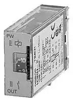


H3RN-2 24VAC
Analogue Timer, Socket, 8-Pin, 24 VAC, DPST-NO, 0.1s - 1s, IP40
- Manufacturer: OMRON INDUSTRIAL AUTOMATION
- Product type: Analogue Timers
- SVHC: To Be Advised
| Delivery and price | |
|---|---|
| Units per pack | 1 |
| Price | 44.63 € |
| Current stock | 10+ |
| Lead time | 30 days |
**Solid-state timer H3RN**

CSM_H3RN_DS_E_3_2

## **Ultra-slim Timer for G2R Relay Socket**

- Pin configuration compatible with G2R Relay and mounts to the P2R/P2RF Socket.

- Standard multiple time ranges and multiple operating modes.

- Conforms to EN61812-1 and IEC60664-1 4 kV/2 for Low Voltage, and EMC Directives.

For the most recent information on models that have been certified for safety standards, refer to your OMRON website.

## **Model Number Structure**

## ■ **Model Number Legend**

## **H3RN-** @@

**1  2**

## **1. Output**

1: SPDT 2: DPST-NO

## **2. Time Range**

None: Short-time range (0.1 s to 10 min)

- 1: Long-time range (0.1 min to 10 hrs)

## **Orderin Information g**

## ■ **List of Models**

|**Supply voltage**|**Time-limit contact**|**Short-time range model**<br>**(0.1 s to 10 min)**|**Long-time range model**<br>**(0.1 min to 10 h)**|
|---|---|---|---|
|24 VAC;<br>12, 24 VDC|SPDT|H3RN-1|H3RN-11|
||DPST-NO|H3RN-2|H3RN-21|


**Note:** Specify both the model number and supply voltage when ordering. Example: H3RN-1   24 VAC

Supply voltage

## ■ **Accessories (Order Separately)**

## **Connecting Socket**

|**Connecting Socket**|||
|---|---|---|
|**Timer**|**Track mounting/Front connecting socket**|**Back connecting socket**|
|H3RN-1/-11|P2RF-05-E|P2R-057P|
|H3RN-2/-21|P2RF-08-E|P2R-087P|


**1**

**H3RN**

## **S ecifications p**

## ■ **Ratings**

|■**Ratings**|||
|---|---|---|
|**Item**|**H3RN-1/H3RN-2**|**H3RN-11/H3RN-21**|
|**Time ranges**|0.1 s to 10 min (1 s, 10 s, 1 min, or 10 min max.<br>selectable)|0.1 min to 10 h (1 min, 10 min, 1 h, or 10 hrs max.<br>selectable)|
|**Rated supply voltage (See note 2.)**|24 VAC (50/60 Hz); 12, 24 VDC||
|**Pin type**|Plug-in||
|**Operating mode**|ON-delay, interval, flicker OFF-start, or flicker-ON start selectable byDIP switch||
|**Operating voltage range**|85% to 110% of rated supply voltage (12 VDC: 90% to 110% of rated supply voltage)<br>(See note 1.)||
|**Reset voltage**|10% max. of rated supplyvoltage||
|**Power consumption**|24 VAC: Relay ON: approx. 0.8 VA<br>12 VDC: Relay ON: approx. 0.5 W<br>24 VDC: RelayON: approx. 0.4 W||
|**Control outputs**|3 A at 250 VAC, resistive load (cosφ= 1) (G6B-2@14P-FD-US used (Contact materials : AgSnIn))<br>The minimum applicable load is 10 mA at 5 VDC (P reference value).||


- **Note: 1.** When using the H3RN in any place where the ambient temperature is more than 50°C, supply 90% to 110% of the rated voltages (12 VDC: 95% to 110% of the rated voltage).

   **2.** Refer to _Safety Precautions for All Times_ when combining the Timer with an AC 2-wire proximity sensor.

## ■ **Characteristics**

|■**Characteristics**|||
|---|---|---|
|**Item**|**H3RN-1/H3RN-2**|**H3RN-11/H3RN-21**|
|**Accuracy of operating time**|±1% FS max. (1 s range:±1%±10 ms max.)||
|**Setting error**|±15%±50 ms FS max.||
|**Reset time**|Min. power-opening time: 12, 24 VDC: 0.1 s max. (including halfway reset)<br>24 VAC:<br>0.5 s max. (includinghalfwayreset)||
|**Influence of voltage**|±2% FS max.||
|**Influence of temperature**|±2% FS max.||
|**Insulation resistance**|100 MΩmin. (at 500 VDC)||
|**Dielectric strength**|2,000 VAC, 50/60 Hz for 1 min (between operating circuit and control output, or contacts of different<br>poles)<br>1,000 VAC, 50/60 Hz for 1 min(between non-continuous contacts)||
|**Vibration resistance**|Destruction: 10 to 55 Hz, 0.75-mm single amplitude for 1 h each in 3 directions<br>Malfunction: 10 to 55 Hz, 0.5-mm single amplitude for 10 min each in 3 directions||
|**Shock resistance**|Destruction: 300 m/s2<br>Malfunction: 100 m/s2||
|**Ambient temperature**|Operating:<br>−10°C to 55°C (with no icing)<br>Storage:<br>−25°C to 65°C (with no icing)||
|**Ambient humidity**|Operating:<br>35% to 85%||
|**Life expectancy**|Mechanical: 10,000,000 operations min. (under no load at 1,800 operations/h)<br>Electrical:<br>100,000 operations min. (3 A at 250 VAC, resistive load at 1,800 operations/h)||
|**Impulse withstand voltage**|Between power terminals: 1 kV||
|**Noise immunity**|±1.5 kV, square-wave noise bynoise simulator (pulse width: 100 ns/1μs, 1-ns rise)||
|**Static immunity**|Destruction: 8 kV<br>Malfunction: 4 kV||
|**Degree ofprotection**|IP40(Terminal screw sections are excluded.)||
|**Weight**|Approx. 18g||
|**EMC**|(EMI)<br>EN61812-1<br>Emission Enclosure:<br>EN55011 Group 1 class A<br>Emission AC Mains:<br>EN55011 Group 1 class A<br>(EMS)<br>EN61812-1<br>Immunity ESD:<br>IEC61000-4-2<br>Immunity RF-interference:<br>IEC61000-4-3<br>Immunity Burst:<br>IEC61000-4-4<br>Immunity Surge:<br>IEC51000-4-5<br>Immunity Conducted Disturbance:<br>IEC61000-4-6<br>ImmunityVoltage Dip/Interruption:<br>IEC61000-4-11||
|**Approved standards**|UL508, CSA C22.2 No. 14<br>Conforms to EN61812-1, IEC60664-1 4 kV/2.<br>Output categoryaccordingto IEC60947-5-1.||


**2**

**H3RN**

## **Connections**

## ■ **Connection**

**H3RN-1/H3RN-11**

**H3RN-2/H3RN-21**

**==> picture [415 x 114] intentionally omitted <==**

**----- Start of picture text -----**<br>
DIN Indication DIN Indication<br>ea st, ee' 1] e:at _<br>Time r  Time r<br>circuit circuit<br>OUT PW OUT PW<br>ons ak<br>Bottom View Bottom View<br>**----- End of picture text -----**<br>


## **Pulse Operation**

A pulse output for a certain period can be obtained with a random external input signal. Use the H3RN in interval mode as shown in the following timing charts.

## **H3RN-2/H3RN-21**

**==> picture [352 x 112] intentionally omitted <==**

**----- Start of picture text -----**<br>
Power (3-8)<br>External short circuit (1-4)<br>50 ms<br>External input (1-3) min.<br>ioe Thal po<br>Time limit contact<br>Ft Timer  NO (6-5) —<br>circuit<br>Run/Power indicator (PW)<br>Output indicator (OUT)<br>External input Note:  t:  Set time<br>Rt:  Reset time<br>“ “2<br>**----- End of picture text -----**<br>


## ~~!Caution~~

Be careful when connecting wires.

|**Mode**|**Terminals**|
|---|---|
|**Pulse operation**|Power supply between 3 and 8<br>Short-circuit between 4 and 1<br>Input signal between 3 and 1|
|**Operating mode; interval and all other**<br>**modes**|Power supply between 1 and 8|


**3** ~~a~~

**H3RN**

## **O eration p**

## ■ **Timing Chart**

|■**Timing Chart**|||
|---|---|---|
|**Operating mode**<br>~~a~~|**Timing chart**||
|~~a~~<br>~~Ge~~|**H3RN-1/H3RN-11**<br>~~Ge~~|**H3RN-2/H3RN-21**<br>~~Ge~~|
|**ON-delay**<br>Power<br>Output|Power (1-5)<br>Time limit contact<br>NC (4-2)<br>Time limit contact<br>NO (4-3)<br>Run/Power<br>indicator (PW)<br>Output indicator<br>(OUT)<br>————=<br>fp &|Power (1-8)<br>Time limit contact<br>NO (4-3, 5-6)<br>Run/Power<br>indicator (PW)<br>Output indicator<br>(OUT)<br>nt<br>mse<br>fl _ia|
|**Interval**<br>Power<br>Output|Power (1-5)<br>Time limit contact<br>NC (4-2)<br>Time limit contact<br>NO (4-3)<br>Run/Power<br>indicator (PW)<br>Output indicator<br>(OUT)|Power (1-8)<br>Time limit contact<br>NO (4-3, 5-6)<br>Run/Power<br>indicator (PW)<br>Output indicator<br>(OUT)<br>=|
|**Flicker OFF-start**<br>Power<br>Output|Power (1-5)<br>Time limit contact<br>NC (4-2)<br>Time limit contact<br>NO (4-3)<br>Run/Power<br>indicator (PW)<br>Output indicator<br>(OUT)<br>t<br>~~i~~<br>t|Power (1-8)<br>Time limit contact<br>NO (4-3, 5-6)<br>Run/Power<br>indicator (PW)<br>Output indicator<br>(OUT)|
|**Flicker ON-start**<br>Power<br>Output|Power (1-5)<br>Time limit contact<br>NC (4-2)<br>Time limit contact<br>NO (4-3)<br>Run/Power<br>indicator (PW)<br>Output indicator<br>(OUT)|Power (1-8)<br>Time limit contact<br>NO (4-3, 5-6)<br>Run/Power<br>indicator (PW)<br>Output indicator<br>(OUT)|


**Note:** t: Set time Rt:Reset time

**4** ~~a~~

**H3RN**

## ■ **DIP Switch Settings**

The 1-s range and ON-delay mode for H3RN-1/-2, 1-min range and ON-delay mode for H3RN-11/-21 are factory-set before shipping.

## **Time Ranges**

|**Model**<br>~~ee~~|**Time range**<br>~~ee~~|**Time setting**<br>**range**<br>~~ee~~|**Setting**|**Factory-set**|
|---|---|---|---|---|
|H3RN-1,<br>H3RN-2<br>~~ee~~|1 s<br>~~ee~~<br>~~|~~|0.1 to 1 s<br>~~ee~~<br>~~|~~|~~|~~|Yes<br>~~|~~|
||10 s<br>~~|~~<br>~~ft~~<br>~~ee~~|1 to 10 s<br>~~|~~<br>~~ft~~<br>~~ee ee~~|~~|~~<br>~~ft~~<br>~~ee~~|No<br>~~|~~<br>~~ft~~<br>~~ee~~|
||1 min<br>~~ee~~|0.1 to 1 min<br>~~ee ee~~|~~ee~~|No<br>~~ee~~<br>~~ee~~|
||10 min<br>~~ee ~~<br>~~ee~~|1 to 10 min<br> ~~ee ee~~<br>~~ee~~|~~ee~~<br>~~ee~~|No<br>~~ee~~<br>~~ee~~<br>~~ee~~|
|H3RN-11,<br>H3RN-21|1 min|0.1 to 1 min||Yes<br>~~ee~~|
||10 min|1 to 10 min||No|
||1 h<br>~~ee~~|0.1 to 1 h||No|
||10 h<br>~~ee~~|1 to 10 h||No|


**Note:** The left two DIP switch pins are used to select the time ranges.

~~a~~ **Operating Modes Operating mode Setting Factory-set** ON-delay Yes ~~a=]~~ Bp) ~~pe~~ Interval No ~~eeee~~ Flicker OFF-startFlicker ON-start ~~ee~~ NoNo

**Note:** The right two DIP switch pins are used to select the operating modes.

## **Nomenclature**

**Run/Power Indicator (Green)** (Lit: Power ON) **Output Indicator (Orange)** (Lit: Output ON)

**Main Dial**

Set the desired time according to time range selectable by DIP switch.

**5**

**H3RN**

## **Dimensions**

**Note:** All units are in millimeters unless otherwise indicated.

## ■ **Timers**

## **H3RN-1/H3RN-11 Front Mounting**

## **H3RN-2/H3RN-21 Front Mounting**

## **Mounting Height**

Use the P2RF-@-E or P2R-@7P to mount the H3RN. When ordering any one of these sockets, replace "@" with "05" for SPDT or "08" for DPST-NO. The P2RF-@ cannot be used because the hook is a different shape.

## **P2RF-** @ **-E P2R-** @ **7P**

**==> picture [228 x 55] intentionally omitted <==**

**----- Start of picture text -----**<br>
H3RN Series<br>80.9 (see note 1)<br>P2RF-@-E  (84.9) (see note 2)<br>Socket<br>79.5 (see note 1)<br>(83.5) (see note 2)<br>**----- End of picture text -----**<br>


**==> picture [38 x 61] intentionally omitted <==**

**----- Start of picture text -----**<br>
H3RN Series<br>P2R-@7P<br>Socket<br>**----- End of picture text -----**<br>


**Note:** 1. The value shown indicates the dimension for the P2RF-05-E with the PFP-@N Mounting Rail.

**Note:** There are no restrictions to the mounting direction.

- The value is 71.5 mm when using the PFP-N@2.

- 2. The value shown in parentheses indicates the dimension for the P2RF-08-E with the PFP-@N Mounting Rail.

   - The value is 75.5 mm when using the PFP-N@2.

**6** ~~a~~

**H3RN**

## **Safet Precautions y**

## ■ **Correct Use**

When using the H3RN in any place where the ambient temperature is more than 50°C, supply 90% to 110% of the rated voltages (at 12 VDC: 95% to 110%).

Do not leave the H3RN in time-up condition (i.e., with the internal relay in an ON state) for a long period of time (for example, more than one month in any place where the ambient temperature is high), otherwise the internal parts may become damaged. Therefore, the use of the H3RN with a relay as shown in the following circuit diagram is recommended.

**==> picture [149 x 63] intentionally omitted <==**

**----- Start of picture text -----**<br>
X2/b T/a X1/a X1/a<br>re ee ee ee<br>T X1 X2<br>**----- End of picture text -----**<br>


X : Auxiliary relay such as G2R Relay

The H3RN must be disconnected from the socket when setting the DIP switch, otherwise the user may touch a terminal imposed with a high voltage and get an electric shock.

Do not connect the H3RN as shown in the following circuit diagram on the right hand side, otherwise the H3RN’s internal contacts different from each other in polarity may become short-circuited.

**==> picture [243 x 95] intentionally omitted <==**

**----- Start of picture text -----**<br>
Correct  Incorrect<br>L2<br>L1  L2  L1<br>a<br>Use the following safety circuit when building a self-holding circuit<br>with the H3RN and an auxiliary relay, such as a G2R Relay, in combi-<br>nation.<br>**----- End of picture text -----**<br>


Do not use the SPDT contact in a circuit which may cause short-circuiting at three points (otherwise, short-circuiting of the power supply may occur) because the SPDT contact of H3RN-1/-11 is composed of an SPST-NC contact.

**==> picture [104 x 96] intentionally omitted <==**

**----- Start of picture text -----**<br>
3<br>Short-circuit current 4<br>yo tSS<br>Power supply<br>for load<br>2<br>1 5<br>ais<br>**----- End of picture text -----**<br>


Do not set to the minimum setting in the flicker modes, otherwise the contact may be damaged.

Do not use the H3RN in places where there is excessive dust, corrosive gas, or direct sunlight.

Make sure that there is a space of 3 mm or more between any H3RN Models next to each other. (When using the P2RF-@-E Socket, a space of 3 mm or more will be secured.) If a space of 3 mm or more is not secured, the ambient temperature must be less than 50°C.

The internal parts may become damaged if a supply voltage other than the rated ones is imposed on the H3RN.

## ■ **Precautions for EN61812-1 Conformance**

The H3RN as a built-in timer conforms to EN61812-1 provided that the following conditions are satisfied.

## **Handling**

Do not touch the DIP switch while power is supplied to the H3RN. Before dismounting the H3RN from the socket, make sure that no voltage is imposed on any terminal of the H3RN.

## **Wiring**

Basic insulation is ensured between the H3RN’s operating circuit and control output.

**==> picture [31 x 7] intentionally omitted <==**

**----- Start of picture text -----**<br>
G2R Relay<br>**----- End of picture text -----**<br>


In the case of the above circuit, the H3RN will be in pulse operation. Therefore, if the circuit shown on page 3 is used, no auxiliary relay will be required.

Overvoltage category III, pollution degree 2 (with a clearance of 3.0 mm and a creepage distance of 3.0 mm at 240 VAC)

Basic insulation:

The clearance from the edge of the P2R-087P Socket to internal, current-carrying metal parts is 1.3 mm. Position the H3RN to provide the necessary clearance for the voltage used.

When using the P2RF-@-E or P2R-057P Socket, basic insulation is ensured in the mounted condition for a voltage of 250 VAC max.

ALL DIMENSIONS SHOWN ARE IN MILLIMETERS.

To convert millimeters into inches, multiply by 0.03937. To convert grams into ounces, multiply by 0.03527.

In the interest of product improvement, specifications are subject to change without notice.

**7**

## Terms and Conditions Agreement

## Read and understand this catalog.

Please read and understand this catalog before purchasing the products.  Please consult your OMRON representative if you have any questions or comments.

## Warranties.

(a) Exclusive Warranty. Omron’s exclusive warranty is that the Products will be free from defects in materials and workmanship for a period of twelve months from the date of sale by Omron (or such other period expressed in writing by Omron). Omron disclaims all other warranties, express or implied.

(b) Limitations. OMRON MAKES NO WARRANTY OR REPRESENTATION, EXPRESS OR IMPLIED, ABOUT NON-INFRINGEMENT, MERCHANTABILITY OR FITNESS FOR A PARTICULAR PURPOSE OF THE PRODUCTS. BUYER ACKNOWLEDGES THAT IT ALONE HAS DETERMINED THAT THE

PRODUCTS WILL SUITABLY MEET THE REQUIREMENTS OF THEIR INTENDED USE.

Omron further disclaims all warranties and responsibility of any type for claims or expenses based on infringement by the Products or otherwise of any intellectual property right. (c) Buyer Remedy. Omron’s sole obligation hereunder shall be, at Omron’s election, to (i) replace (in the form originally shipped with Buyer responsible for labor charges for removal or replacement thereof) the non-complying Product, (ii) repair the non-complying Product, or (iii) repay or credit Buyer an amount equal to the purchase price of the non-complying Product; provided that in no event shall Omron be responsible for warranty, repair, indemnity or any other claims or expenses regarding the Products unless Omron’s analysis confirms that the Products were properly handled, stored, installed and maintained and not subject to contamination, abuse, misuse or inappropriate modification. Return of any Products by Buyer must be approved in writing by Omron before shipment. Omron Companies shall not be liable for the suitability or unsuitability or the results from the use of Products in combination with any electrical or electronic components, circuits, system assemblies or any other materials or substances or environments. Any advice, recommendations or information given orally or in writing, are not to be construed as an amendment or addition to the above warranty.

See http://www.omron.com/global/ or contact your Omron representative for published information.

## Limitation on Liability; Etc.

OMRON COMPANIES SHALL NOT BE LIABLE FOR SPECIAL, INDIRECT, INCIDENTAL, OR CONSEQUENTIAL DAMAGES, LOSS OF PROFITS OR PRODUCTION OR COMMERCIAL LOSS IN ANY WAY CONNECTED WITH THE PRODUCTS, WHETHER SUCH CLAIM IS BASED IN CONTRACT, WARRANTY, NEGLIGENCE OR STRICT LIABILITY. Further, in no event shall liability of Omron Companies exceed the individual price of the Product on which liability is asserted.

## Suitability of Use.

Omron Companies shall not be responsible for conformity with any standards, codes or regulations which apply to the combination of the Product in the Buyer’s application or use of the Product. At Buyer’s request, Omron will provide applicable third party certification documents identifying ratings and limitations of use which apply to the Product. This information by itself is not sufficient for a complete determination of the suitability of the Product in combination with the end product, machine, system, or other application or use. Buyer shall be solely responsible for determining appropriateness of the particular Product with respect to Buyer’s application, product or system. Buyer shall take application responsibility in all cases.

NEVER USE THE PRODUCT FOR AN APPLICATION INVOLVING SERIOUS RISK TO LIFE OR PROPERTY OR IN LARGE QUANTITIES WITHOUT ENSURING THAT THE SYSTEM AS A WHOLE HAS BEEN DESIGNED TO ADDRESS THE RISKS, AND THAT THE OMRON PRODUCT(S) IS PROPERLY RATED AND INSTALLED FOR THE INTENDED USE WITHIN THE OVERALL EQUIPMENT OR SYSTEM.

## Programmable Products.

Omron Companies shall not be responsible for the user’s programming of a programmable Product, or any consequence thereof.

## Performance Data.

Data presented in Omron Company websites, catalogs and other materials is provided as a guide for the user in determining suitability and does not constitute a warranty. It may represent the result of Omron’s test conditions, and the user must correlate it to actual application requirements. Actual performance is subject to the Omron’s Warranty and Limitations of Liability.

## Change in Specifications.

Product specifications and accessories may be changed at any time based on improvements and other reasons. It is our practice to change part numbers when published ratings or features are changed, or when significant construction changes are made. However, some specifications of the Product may be changed without any notice. When in doubt, special part numbers may be assigned to fix or establish key specifications for your application. Please consult with your Omron’s representative at any time to confirm actual specifications of purchased Product.

## Errors and Omissions.

Information presented by Omron Companies has been checked and is believed to be accurate; however, no responsibility is assumed for clerical, typographical or proofreading errors or omissions.

**In the interest of product improvement, specifications are subject to change without notice.**

## **OMRON Corporation**

## **Industrial Automation Company**

2015.9

**http://www.ia.omron.com/**

(c)Copyright OMRON Corporation 2015 All Right Reserved.
Updated at April 29, 2026
With a legacy spanning over 80 years, Omron Industrial Automation is a globally recognized leader in the manufacture of advanced industrial control and automation components. Renowned for their reliability and engineering excellence, Omron delivers comprehensive solutions that enhance efficiency, machine safety, and precision across a wide range of manufacturing environments. Our extensive portfolio of Omron products is heavily focused on their industry-leading sensing and switching technologies. We offer a vast selection of sensors, excelling specifically in high-performance proximity sensors, light sensors, and temperature sensors. Complementing this range are robust switching solutions, featuring a deep inventory of power relays, solid-state relays, safety relays, and essential relay accessories designed for demanding operational requirements. Beyond sensing and switching, Omron is highly regarded for its precision automation and process control equipment. Our selection features highly accurate temperature controllers, versatile process controllers, and sophisticated panel displays and instrumentation. To support these fundamental systems, we also supply dependable Omron power supplies, notably AC/DC converters, alongside vital connectivity components like DIN rail terminal blocks to ensure secure, efficient, and complete industrial setups.
About Novapart
Novapart is a B2B electronic component broker specialising in stock shortages and cost reduction. We source hard-to-find parts and identify compliant alternatives across a catalogue of 410,000+ components from 500+ manufacturers.
Learn more →Stock Shortage Specialist
When a component is unavailable, discontinued or has an unacceptable lead time, we tap into our network of vetted European and Asian distributors to source what you need — without compromising on quality or traceability.
Request a quote →Compliant Alternatives
We identify pin-to-pin, electrically equivalent substitutes that meet the same certifications (RoHS, AEC-Q100, REACH) as your original specification — validated against datasheets, not just part numbers. Often at a lower cost.
BOM Analysis service →