
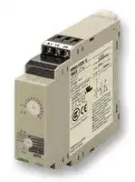


H3DK-GE AC240-440
Analogue Timer, Star-Delta, 1 s, 120 s, 2 Ranges, Solid State
- Manufacturer: OMRON INDUSTRIAL AUTOMATION
- Product type: Analogue Timers - DIN Rail
- Product Range:-; Timer Functions:Star-Delta; Time Min:1s; Time Max:120s; No. of Timing Ranges:2Ranges; Timer Output:Solid State; Supply Voltage Max:440VAC; Current Rating Nom:5A; Conne
- SVHC: No SVHC (17-Dec-2014)
- Time Max: 120s
- Time Min: 1s
- Timer Output: Solid State
- Product Range: -
- Timer Functions: Star-Delta
- Current Rating Nom: 5A
- Supply Voltage Max: 440VAC
- No. of Timing Ranges: 2Ranges
- Connection / Termination: Screw Terminals
| Delivery and price | |
|---|---|
| Units per pack | 1 |
| Price | 50.68 € |
| Current stock | 10+ |
| Lead time | 30 days |
**New Product News** ~~|~~

## **Solid-state Timers H3DK**

## **DIN Track-mounted, 22.5-mm-width Standard Timer Series**

## LR

- **A wide AC/DC power supply range (24 to 240 VAC/DC).*[1]**

- **All sub-series include models with 12-VDC power supply.*[1]**

- **G-type Models (H3DK-G) now include model with 240 to 440VAC power supply.**

- **UL*[2] , CSA*[3] , and CCC certification and EN 61812-1 compliance. CE Marking.**

- **EMC (EN 61812-1) compliance for application in heavy industrial, residential, commercial, or light industrial environments.**

- **Finger-safe terminal block and captive screws according to EN 50274.**

- *1. Except for the H3DK-H.

- *2. Except for the H3DK-GE.

- *3. Scheduled to obtain certification in April 2012.

For the most recent information on models that have been certified for safety standards, refer to your OMRON website.

## **Model Number Structure**

■ **The Entire H3DK Series**

H3DK Series ~~|~~

**==> picture [497 x 265] intentionally omitted <==**

**----- Start of picture text -----**<br>
H3DK-M/-S Multi-range,  H3DK-F  H3DK-G  H3DK-H Power<br>Multi-mode Timers Twin Timers Star-delta Timers OFF-delay Timers<br>aoe Ce £ me<br>Page 2 Page 11 Page 15 Page 21<br>■ Eight-mode Timer  ● Operating Modes ● Operating Modes  ● Operating Modes<br>H3DK-M1/M2 Flicker-OFF Start/ Star-delta Timer Power  OFF-delay<br>● Operating Modes Flicker-ON Start Timer<br>A: ON Delay<br>B: Flicker OFF Start<br>B2: Flicker ON Start<br>C: Signal ON/OFF Delay<br>D: Signal OFF Delay<br>E: Interval<br>G: Signal ON/OFF Delay<br>J: One-shot Output<br>■ Four-mode Timer<br>H3DK-S1/S2<br>● Operating Modes<br>A: ON Delay<br>B2: Flicker ON Start<br>E: Interval<br>J: One-shot Output<br>**----- End of picture text -----**<br>


■ **Model Number Legend** (Not all models that can be represented with the model number legend can necessarily be produced.)

## **H3DK-** @@@@

**1 2 3 4**

## **2. Control Output**

## **1. Type**

|Symbol|Meaning||Symbol|Meaning|
|---|---|---|---|---|
|M|Eight-mode Timer||1|SPDT|
|S|Four-mode Timer||2|DPDT|
|F<br>G|Twin Timer<br>Star-delta Timer||* M- and S-type models only.||
|H|Power OFF-delayTimer||||


## **3. Supply Voltage**

|Symbol|Meaning|
|---|---|
|Blank|24 to 240 VAC/DC|
|A|12 VDC|
|B|24 to 48 VAC/DC|
|C *1|100 to 120 VAC|
|D *1|200 to 240 VAC|
|E *1|240 to 440 VAC *2|


**4. Time Ranges (H-type Models Only)**

|Symbol|Meaning|
|---|---|
|S|0.1 to 1.2 s or 1 to 12 s|
|L|1 to 12 s or 10 to 120 s|


- *1 H-type models only.

- *2 G-type models only.

**1** omrRON ~~a~~

**New Product News** ~~|~~

## **Multi-range, Multi-mode Timer H3DK-M/H3DK-S**

- **Multiple time ranges and operating modes let you cover a wide range of applications.**

## LR

- **The time-limit DPDT output contacts can be changed to time-limit SPDT and instantaneous SPDT output contacts using a switch.**

- **Sequence checks are easily performed by setting an instantaneous output to 0.**

- **Start signal control for the H3DK-M.**

For the most recent information on models that have been certified for safety standards, refer to your OMRON website.

## **Ordering Information**

## ■ **List of Models**

|Supply voltage<br>Control output|Supply voltage<br>Control output|Supply voltage<br>Control output|Eight-mode Timer|Four-mode Timer|
|---|---|---|---|---|
|24 to 240 VAC/DC|Contact output, DPDT (time-limit DPDT, or time-limit<br>SPDT + instantaneous SPDT)<br>Changed using a switch.|Model|**H3DK-M2**|**H3DK-S2**|
||Contact output, SPDT (time-limit SPDT)|Model|**H3DK-M1**|**H3DK-S1**|
|12 VDC|Contact output, DPDT (time-limit DPDT, or time-limit<br>SPDT + instantaneous SPDT)<br>Changed using a switch.|Model|**H3DK-M2A**|**H3DK-S2A**|
||Contact output, SPDT (time-limit SPDT)|Model|**H3DK-M1A**|**H3DK-S1A**|


## ■ **Accessories (Order Separately)**

|Item|Specification|Model|
|---|---|---|
|Mounting Track|50 cm (l) x 7.3 mm (t)|**PFP-50N**|
||1 m (l) x 7.3 mm (t)|**PFP-100N**|
||1 m (l) x 16 mm (t)|**PFP-100N2**|
|End Plate|---|**PFP-M**|
|Spacer|---|**PFP-S**|


## ■ **Model Structure**

|Model|Operating modes|Terminal block|Input type|Output type|Mounting method|Safety standards|Accessories|
|---|---|---|---|---|---|---|---|
|H3DK-M2|A: ON Delay<br>B: Flicker OFF start<br>B2: Flicker ON start<br>C: Signal ON/OFF Delay<br>D: Signal OFF Delay<br>E: Interval<br>G: Signal ON/OFF Delay<br>J: One-shot Output|9 terminals|Voltage input|Relay, DPDT|DIN Track mounting|cURus (UL 508<br>CSA C22.2 No. 14)<br>EN 61812-1<br>IEC 60664-1 4 kV/2<br>EN 50274|User label|
|H3DK-M1||||Relay, SPDT||||
|H3DK-S2|A: ON Delay<br>B2: Flicker ON start<br>E: Interval<br>J: One-shot Output||---|Relay, DPDT||||
|H3DK-S1||6 terminals||Relay, SPDT||||


**2** ~~a~~

**H3DK-M/H3DK-S**

**Specifications**

## ■ **Time Ranges**

|■**Time Ranges**|■**Time Ranges**||||||||||
|---|---|---|---|---|---|---|---|---|---|---|
|Time range setting||0.1 s||1 s|10 s|1 min|10 min|1 h|10 h|100 h|
|Set time range||0.1 to 1.2 s||1 to 12 s|10 to 120 s|1 to 12 min|10 to 120 min|1 to 12 h|10 to 120 h|100 to 1,200 h|
|Scale numbers||12|||||||||
|■**Ratings**<br>Power supply voltage*1<br>• 24 to 240 VAC/DC, 50/60 Hz*2<br>• 12 VDC*2<br>Allowable voltage fluctuation<br>range<br>• 24 to 240 VAC/DC: 85% to 110% of rated voltage<br>• 12 VDC: 90% to 110% of rated voltage<br>Power reset<br>Minimum power-OFF time: 0.1 s<br>Reset voltage<br>10% of rated voltage<br>Voltage input<br>• 24 to 240 VAC/DC<br>High level: 20.4 to 264 VAC/DC, Low level: 0 to 2.4 VAC/DC<br>• 12 VDC<br>High level: 10.8 to 13.2 VDC, Low level: 0 to 1.2 VDC<br>*3<br>Power con-<br>sumption<br>H3DK-M2/-S2<br>At 240 VAC: 6.6 VA max.*4<br>H3DK-M1/-S1<br>At 240 VAC: 4.5 VA max.*4<br>H3DK-M2A/-S2A<br>At 12 VDC: 0.9 W max.<br>H3DK-M1A/-S1A<br>At 12 VDC: 0.6 W max.<br>Control output<br>Contact output, 5 A at 250 VAC with resistive load (cosφ= 1),<br>5 A at 30 VDC with resistive load*4, *5<br>Ambient operating temperature<br>−20 to 55°C (with no icing)<br>Storage temperature<br>−40 to 70°C (with no icing)<br>Ambient operating humidity<br>25% to 85%<br>*1.<br>When using a 24-VDC power supply voltage, there will<br>be an inrush current of approximately 0.25 A. Allow for<br>this inrush current when turning ON and OFF the<br>power supply to the Timer with device with a solid-<br>state output, such as a sensor.<br>*2.<br>DC ripple: 20% max.<br>*3.<br>The power consumption is for mode A after the Timer<br>times out.<br>For the H3DK-M@, the maximum power consumption<br>is given, including the current consumed by the input<br>circuit.<br>*4.<br>Refer to_DC Power Consumptions (Reference Infor-_<br>_mation)_on page 27 for DC power consumptions.<br>*5.<br>The control output ratings are for one H3DK operating<br>alone. If you operate two or more Timers side by side,<br>refer to_Installation Pitch and Output Switching Capac-_<br>_ity (Reference Values)_on the next page.<br>*6.<br>125 VDC: 0.15 A max. with resistive load, 125 VDC:<br>0.1 A with L/R of 7 ms.<br>Minimum load: 10 mA at 5 VDC (P level, reference<br>value)|||||||||||
|Power supply voltage*1|||• 24 to 240 VAC/DC, 50/60 Hz*2<br>• 12 VDC*2||||||||
|Allowable voltage fluctuation<br>range|||• 24 to 240 VAC/DC: 85% to 110% of rated voltage<br>• 12 VDC: 90% to 110% of rated voltage||||||||
|Power reset|||Minimum power-OFF time: 0.1 s||||||||
|Reset voltage|||10% of rated voltage||||||||
|Voltage input|||• 24 to 240 VAC/DC<br>High level: 20.4 to 264 VAC/DC, Low level: 0 to 2.4 VAC/DC<br>• 12 VDC<br>High level: 10.8 to 13.2 VDC, Low level: 0 to 1.2 VDC||||||||
|*3<br>Power con-<br>sumption|H3DK-M2/-S2||At 240 VAC: 6.6 VA max.*4||||||||
||H3DK-M1/-S1||At 240 VAC: 4.5 VA max.*4||||||||
||H3DK-M2A/-S2A||At 12 VDC: 0.9 W max.||||||||
||H3DK-M1A/-S1A||At 12 VDC: 0.6 W max.||||||||
|Control output|||Contact output, 5 A at 250 VAC with resistive load (cosφ= 1),<br>5 A at 30 VDC with resistive load*4, *5||||||||
|Ambient operating temperature|||−20 to 55°C (with no icing)||||||||
|Storage temperature|||−40 to 70°C (with no icing)||||||||
|Ambient operating humidity|||25% to 85%||||||||


**3**

**H3DK-M/H3DK-S**

## ■ **Characteristics**

## ● **Installation Pitch and Output Switching Capacity (Reference Values)**

|||||||
|---|---|---|---|---|---|
|Accuracy of operating<br>time||±1% of FS max. (±1%±10 ms max. at 1.2-s range)*||●**Installation Pitch and Output**<br>**Switching Capacity (Reference Val-**||
|Setting error||±10% of FS±0.05 s max.*||**ues)**||
|Minimum input signal<br>width||50 ms* (start input)||The relation between the installation pitch||
|Influence of voltage||±0.5% of FS max. (±0.5%±10 ms max. at 1.2-s range)||and the load current is shown in the follow-||
|Influence of tempera-<br>ture||±2% of FS max. (±2%±10 ms max. at 1.2-s range)||ing graph. (Except for the H3DK-GE)<br>If Timer is used under load conditions that||
|Insulation resistance||100 MΩmin. at 500 VDC||exceed the specified values, the tempera-||
|||Between current-carrying metal parts and exposed non-current-carrying metal||ture inside the Timer will increase, reducing||
|Dielectric strength<br>Impulse withstand volt-<br>age<br>Noise immunity<br>Static immunity<br>Vibration<br>resistance<br>Destruction<br>Malfunction<br>Shock re-<br>sistance<br>Destruction<br>Malfunction||parts: 2,000 VAC 50/60 Hz for 1 min.<br>Between control output terminals and operating circuit: 2,000 VAC 50/60 Hz for<br>1 min.<br>Between contacts not located next to each other: 1,000 VAC 50/60 Hz for<br>1 min.<br>24 to 240 VAC/VDC: 3 kV between power terminals, 4.5 kV between current-<br>carrying metal parts and exposed non-current-carrying metal parts<br>12 VDC: 1 kV between power terminals, 1.5 kV between current-carrying metal<br>parts and exposed non-current-carrying metal parts<br>Square-wave noise generated by noise simulator (pulse width: 100 ns/1μs,<br>1-ns rise):±1.5 kV<br>Malfunction: 4 kV, Destruction: 8 kV<br>0.75-mm single amplitude at 10 to 55 Hz for 2 h each in 3 directions<br>0.5-mm single amplitude at 10 to 55 Hz for 10 min each in 3 directions<br>1,000 m/s23 times each in 6 directions<br>100 m/s23 times each in 6 directions||the life expectancy of internal parts.<br>0<br>1<br>2<br>3<br>4<br>5<br>6<br>80<br>70<br>60<br>50<br>40<br>30<br>20<br>10<br>d = 5 mm<br>d=0 mm<br>d = 10 mm<br>d = 50 mm<br>Ambient temperature (°C)<br>Maximum ambient operating<br>temperature in specifications||
|Life ex-<br>Mechanical||10 million operations min. (under no load at 1,800 operations/h)||Load current (A)||
|pectancy<br>Electrical||100,000 operations min. (5 A at 250 VAC, resistive load at 360 operations/h)||Testing Method||
|||||Tested Timer: H3DK-M/-S||
|Degree of protection||IP30 (Terminal block: IP20)||Applied voltage: 240 VAC||
|Weight||Approx. 120 g||Installation pitch: 0, 5, 10, and 50 mm||
|* With the H3DK-M@, if the voltage exceeds 26.4 VAC/DC in mode C, D, or G, the OFF trigger signal char-||||Test<br>Test<br>Test<br>Test<br>Test||
|acteristics are as follows:||||timer<br>timer<br>timer<br>timer<br>timer||
|Accuracy of operating time:±1%±50 ms max.<br>Setting error:±10%<br>max.<br>Minimum input signal width: 100 ms<br>+100 ms<br>−50 ms||||DIN Track<br>Timer installation pitch: d<br>1<br>2<br>3<br>4<br>5||


## ■ **Applicable standards**

|Safety standards|cURus: UL 508/CSA C22.2 No. 14<br>EN 50274: Finger protection, back-of-hand proof<br>EN 61812-1: Pollution degree 2, Overvoltage category III<br>CCC: Pollution degree 2, Overvoltage category II, section DB14048.5-2008 part 5-1<br>LR: Test Specification No. 1-2002 Category ENV 1.2|
|---|---|
|EMC|(EMI)<br>EN61812-1<br>Radiated Emissions:<br>EN 55011 class B<br>Emission AC Mains:<br>EN 55011 class B<br>Harmonic Current:<br>EN 61000-3-2<br>Voltage Fluctuations and Flicker: EN61000-3-3<br>(EMS)<br>EN61812-1<br>ESD Immunity:<br>EN 61000-4-2: 6 kV contact discharge,<br>8 kV air discharge<br>Radiated Radio-Frequency Electromagnetic Field Immunity (AM Radio Waves):<br>EN 61000-4-3: 10 V/m (80 MHz to 1 GHz)<br>Burst Immunity:<br>EN 61000-4-4: 2 kV power line,<br>1 kV I/O signal line<br>Surge Immunity:<br>EN 61000-4-5: 2 kV common mode,<br>1 kV differential mode|


## ■ **I/O**

|Item<br>Model|Item<br>Model|Item<br>Model|H3DK-M1/-M2|H3DK-S1/-S2|
|---|---|---|---|---|
||Input|Start|Functions to start timing.|There is no start input.|
||Output|Control<br>output|The output is turned ON/OFF according to the operating mode when the value<br>that is set on the dial is reached. *||
|*|If the INST/TIME switch on the front of the Timer is set to INST on the H3DK-M2/-S2, relay R2 will<br>operate as instantaneous contacts and will turn ON/OFF in synchronization with the power supply.||||


**4**

**H3DK-M/H3DK-S**

## **Connections**

## ■ **Block Diagrams**

## **H3DK-M1/-M2**

**==> picture [340 x 188] intentionally omitted <==**

**----- Start of picture text -----**<br>
Time setting  Time specification  Operating mode<br>AC (DC) input detection circuit switches switch<br>ROM RAM Clock<br>Power supply circuit Output circuit<br>One-chip microcomputer<br>Start input Input circuit Indicator circuit<br>Power  Output<br>indicator indicator<br>**----- End of picture text -----**<br>


## **H3DK-S1/-S2**

**==> picture [340 x 188] intentionally omitted <==**

**----- Start of picture text -----**<br>
AC (DC) input detection circuitTime setting  Time specification switches mode switchOperating<br>ROM RAM Clock<br>Power supply circuit Output circuit<br>One-chip microcomputer<br>Indicator circuit<br>Power  Output<br>indicator indicator<br>**----- End of picture text -----**<br>


**5**

**H3DK-M/H3DK-S**

## ■ **Terminal Arrangement**

**==> picture [482 x 178] intentionally omitted <==**

**----- Start of picture text -----**<br>
H3DK-M1 H3DK-M2 H3DK-S1 H3DK-S2<br>A1 15 A1 15 25/21 A1 15 A1 15 25/21<br>* *<br>R1 R1 R2 R1 R1 R2<br>15 15 25/21 15 15 25/21<br>18 16 18 16 28/24 26/22 18 16 18 16 28/24 26/22<br>B1 28/24 26/22 B1 28/24 26/22<br>Start Start<br>18 16 A2 18 16 A2 18 16 A2 18 16 A2<br>See note 3.  See note 3.  See note 3.  See note 3.<br>**----- End of picture text -----**<br>


Note 1: The time-limit contact symbol for previous models of Timers was      . The time-limit contact symbol for the H3DK is      .  A different symbol is used because the H3DK supports multiple operating modes.

Note 2: *The relay R2 can be set to either instantaneous or time-limit contacts using the switch on the front of the Timer. Note 3: The power supply terminals do not have polarity.

**==> picture [450 x 63] intentionally omitted <==**

**----- Start of picture text -----**<br>
(DIN notation) (DIN notation) (DIN notation) (DIN notation)<br>(21)<br>15 15 (21)25 A1 15 A1 15 25<br>A1 B1 A1 B1<br>A2 A2<br>A2 A2 16 18 16 18 26 28<br>16 18 16 18 26 28 (22)(24)<br>(22)(24)<br>**----- End of picture text -----**<br>


## ■ **Input Connections**

The start input of the H3DK-M1/-M2 is a voltage input.

**PNP Transistor Input**

**NPN Transistor Input**

## **Relay Input**

## **Voltage Input Signal Levels**

**==> picture [513 x 235] intentionally omitted <==**

**----- Start of picture text -----**<br>
Sensor 1. Transistor ON<br>Sensor 24 VDC (sensor  Timer 24 VDC (sensor  Timer Timer • Residual voltage: 1 V max.<br>power supply) A1 (+) power supply) A1 (−) A1 Voltage between terminals B1<br>and A2 must be equal to or<br>24 VDC (+)(−) B1  24 VDC ((+)−) B1  B1  Tran-sistor  higher than the rated high level voltage (20.4 VDC min.).<br>Start Start Start input 2. Transistor OFF<br>A2 (−) A2 (+) A2 • Leakage current: 0.01 mA max.<br>Voltage between terminals B1<br>Operates when PNP transistor turns ON. Operates when NPN transistor turns ON. Operates when relay turns ON. and A2 must be equal to or<br>Consider the minimum load  below the rated low level voltage<br>(2.4 VDC min.).<br>of the relay. (See signal<br>levels on the right.)  Use relays that can adequately<br>switch 0.1 mA at the imposed<br>voltage.<br>When the relay is ON or OFF, the<br>voltage between terminals B1 and<br>A2 must be within the following<br>Relay  ranges:<br>input • 24 to 240 VAC/DC<br>When relay is ON: 20.4 to 264<br>VAC/DC<br>When relay is OFF: 0 to 2.4 V<br>• 12 VDC<br>When relay is ON: 10.8 to 13.2 V<br>When relay is OFF: 0 to 1.2 V<br>**----- End of picture text -----**<br>


**6**

**H3DK-M/H3DK-S**

## **Nomenclature**

## **H3DK-M2 H3DK-S2**

**==> picture [35 x 6] intentionally omitted <==**

**----- Start of picture text -----**<br>
Front View<br>**----- End of picture text -----**<br>


## Bottom View

**==> picture [511 x 189] intentionally omitted <==**

**----- Start of picture text -----**<br>
Note 1. Use solid wire (2.5 mm [2]  max.) or fer-<br>rules with insulative sleeves to connect<br>User label  to the terminals.<br>attachment location Terminal Block To maintain the withstand voltage after<br>Time range switch (See notes 1 and 2.)  connecting the terminals, insert no<br>more than 8 mm of exposed conductor<br>Output indicator (orange)  Main dial (for  into the terminal.<br>(Lit while Timer gives output.) setting the time)<br>Using Solid Wire  Using Ferrule with<br>(2.5 mm [2]  Max.) Insulative Sleeve<br>Operation/power indicator (green)<br>(Lit while the power is ON.)<br>Operating mode switch 8 mm max. 8 mm max.<br>Recommended Ferrules<br>Phoenix Contact<br>INIT/TIME switch for relay R2<br>(Default setting is for time-limit  • AI@@@ Series<br>output.)* • AI-TWIN@@@ Series<br>Note 2. Screw Tightening Torque<br>Recommended torque: 0.49 N·m<br>Maximum torque: 0.98 N·m<br>*If the switch is left between settings, proper operation may not be possible.<br>**----- End of picture text -----**<br>


*If the switch is left between settings, proper operation may not be possible. Make sure that the switch is set properly.

Note: The default settings are for 0.1 s in mode A.

## **H3DK-M1**

**==> picture [235 x 197] intentionally omitted <==**

**----- Start of picture text -----**<br>
Front View<br>User label attachment<br>location<br>Time range switch<br>Output indicator (orange)  Main dial<br>(Lit while Timer gives output.) (for setting the time)<br>Operation/power indicator (green)<br>(Lit while the power is ON.)<br>Operating mode switch<br>**----- End of picture text -----**<br>


*If the switch is left between settings, proper operation may not be possible. Make sure that the switch is set properly. Note: The default settings are for 0.1 s in mode A.

## **H3DK-S1**

**==> picture [34 x 6] intentionally omitted <==**

**----- Start of picture text -----**<br>
Front View<br>**----- End of picture text -----**<br>


**==> picture [237 x 179] intentionally omitted <==**

**----- Start of picture text -----**<br>
User label attachment<br>location<br>Time range switch*<br>Output indicator (orange)  Main dial<br>(Lit while Timer gives output.) (for setting the time)<br>Operation/power indicator (green)<br>(Lit while the power is ON.)<br>Operating mode switch*<br>**----- End of picture text -----**<br>


*If the switch is left between settings, proper operation may not be possible. Make sure that the switch is set properly.

Note: The default settings are for 0.1 s in mode A.

**7**

**H3DK-M/H3DK-S**

**Dimensions**

**(Unit: mm)**

## ■ **Timers**

## **H3DK-M H3DK-S**

**==> picture [454 x 144] intentionally omitted <==**

**----- Start of picture text -----**<br>
100<br>88.2<br>22.5 22.5 22.5 69.1<br>4<br>f “Ge wB e ee @a  ae£5 ieCE, iane, =LHe, o qr e i 4<br>fe ee 79 65.6 52 - a g. 89.4<br>ae Hi cho, ho, Es}<br>H3DK-M2 H3DK-M1<br>H3DK-S2 H3DK-S1<br>H3DK-M2 H3DK-M1 H3DK-S1<br>H3DK-S2<br>**----- End of picture text -----**<br>


## ■ **Track Mounting Products (Sold Separately)**

Refer to page 28 for details.

## **Operating Procedures**

## ■ **Basic Operation**

## ● **Setting Switches**

- Each switch has a snap mechanism that secures the switch at given positions. Set the switch to one of these positions. Do not set it midway between two positions. Malfunction could result from an improper setting.

## **Setting the Operating Mode**

## ● **Setting the Operating Mode**

The H3DK-M can be set to any of eight operating modes. The H3DK-S can be set to any of four operating modes. Turn the operating mode switch with a flatblade or Phillips screwdriver. The H3DKM can be set to any of eight modes; the H3DK-S, to any of four modes.

## **Setting the INIT/TIME Switch**

## ● **Switching Relay R2 between Instantaneous and Time-limit Contacts (H3DK-M2/-S2 Only)**

The INIT/TIME switch can be used to switch relay R2 between instantaneous and time-limit operation.

## **Setting the Time Range**

## ● **Setting the Time Range**

The time range switch can be used to set the time range. Turn the switch with a flat-blade or Phillips screwdriver.

**==> picture [29 x 12] intentionally omitted <==**

**----- Start of picture text -----**<br>
Time range<br>switch<br>**----- End of picture text -----**<br>


**==> picture [32 x 12] intentionally omitted <==**

**----- Start of picture text -----**<br>
Operating<br>mode switch<br>**----- End of picture text -----**<br>


**==> picture [27 x 12] intentionally omitted <==**

**----- Start of picture text -----**<br>
INIT/TIME<br>switch<br>**----- End of picture text -----**<br>


**8**

**H3DK-M/H3DK-S**

## ■ **Timing Charts**

- There is no start input with the H3DK-S. Timer operation starts when the power is turned ON.

- There is no instantaneous output with the H3DK-@1.

**==> picture [512 x 652] intentionally omitted <==**

**----- Start of picture text -----**<br>
A: ON Delay<br>t t−a t Basic Operation<br>Power (A1 and A2)<br>Start (B1 and A1)<br>Power<br>Time-limit contacts: NC * **<br>15 and 16 (25 and 26) Start input<br>Time-limit contacts: NO Timing<br>(output indicator)<br>Output<br>15 and 18 (25 and 28)<br>Instantaneous contacts: NC *  For power ON-delay operation, connect start input<br>(21 and 22) terminals B1 and A1.  The Timer starts operating<br>as soon as the power turns ON.<br>Instantaneous contacts: NO ** The start input is ignored while the Timer is in<br>(21 and 24) operation.<br>Power indicator<br>B: Flicker OFF Start<br>t t t−a t t t t−a Basic Operation<br>Power (A1 and A2)<br>Start (B1 and A1) Power<br>Time-limit contacts: NC * **<br>15 and 16 (25 and 26) Start input<br>Time-limit contacts: NO Timing Timing Timing Timing<br>(output indicator) Output<br>15 and 18 (25 and 28)<br>Instantaneous contacts: NC *  To start with the power supply, connect start input<br>(21 and 22) terminals B1 and A1. The Timer starts operating<br>as soon as the power turns ON.<br>Instantaneous contacts: NO ** The start input is ignored while the Timer is in<br>(21 and 24) operation.<br>Power indicator<br>B2: Flicker ON start<br>t t t−a t t t t−a Basic Operation<br>Power (A1 and A2)<br>Start (B1 and A1) Power<br>Time-limit contacts: NC * **<br>15 and 16 (25 and 26) Start input<br>Time-limit contacts: NO Timing Timing Timing Timing<br>(output indicator) Output<br>15 and 18 (25 and 28)<br>Instantaneous contacts: NC *  To start with the power supply, connect start input<br>(21 and 22) terminals B1 and A1. The Timer starts operating<br>as soon as the power turns ON.<br>Instantaneous contacts: NO ** The start input is ignored while the Timer is in<br>(21 and 24) operation.<br>Power indicator<br>C: Signal ON/ OFF Delay<br>t t t t−a t t−a Basic Operation<br>Power (A1 and A2)<br>Start (B1 and A1)<br>Power<br>Time-limit contacts: NC *<br>15 and 16 (25 and 26) Start input<br>Time-limit contacts: NO T imin g T imin g T iming<br>(output indicator)<br>Output<br>15 and 18 (25 and 28)<br>Instantaneous contacts: NC Timin g<br>(21 and 22) *  The start input is valid while the Timer is in<br>operation.<br>Instantaneous contacts: NO<br>(21 and 24)<br>Power indicator<br>**----- End of picture text -----**<br>


Note 1.The reset time is 0.1 s min. Make sure the signal input time is 0.05 s or longer. Note 2.“t” is the set time. “t−a” is a time that is less that the set time.

**9**

## **H3DK-M/H3DK-S**

**==> picture [512 x 652] intentionally omitted <==**

**----- Start of picture text -----**<br>
D: Signal OFF delay<br>t t−a t−a t t−a Basic Operation<br>Power (A1 and A2)<br>Start (B1 and A1)<br>Power<br>Time-limit contacts: NC15 and 16 (25 and 26) *<br>Time-limit contacts: NO Start input<br>(output indicator) T imin g<br>15 and 18 (25 and 28) Output<br>Instantaneous contacts: NC<br>(21 and 22) *  The start input is valid while the Timer is in<br>operation.<br>Instantaneous contacts: NO<br>(21 and 24)<br>Power indicator<br>E: Interval<br>t t t−a t−a t Basic Operation<br>Power (A1 and A2)<br>Start (B1 and A1)<br>Power<br>Time-limit contacts: NC * **<br>15 and 16 (25 and 26) Start input<br>Time-limit contacts: NO<br>(output indicator) T iming<br>15 and 18 (25 and 28) Output<br>Instantaneous contacts: NC<br>*  For power ON-delay operation, connect start input<br>(21 and 22) terminals B1 and A1.  The Timer starts operating<br>Instantaneous contacts: NO ** The start input is valid while the Timer is in as soon as the power turns ON.<br>(21 and 24) operation.<br>Power indicator<br>G: Signal ON/ OFF Delay<br>t t t t−a t t−a Basic Operation<br>Power (A1 and A2)<br>Start (B1 and A1) Power<br>Time-limit contacts: NC *<br>15 and 16 (25 and 26) Start input<br>Time-limit contacts: NO T iming T iming Timin g T iming<br>(output indicator)<br>15 and 18 (25 and 28) Output<br>Instantaneous contacts: NC<br>(21 and 22) *  The start input is valid while the Timer is in<br>operation.<br>Instantaneous contacts: NO<br>(21 and 24)<br>Power indicator<br>J: One-shot Output (ON delay)<br>t t t−a t−a t Basic Operation<br>Power (A1 and A2)<br>Start (B1 and A1)<br>Power<br>Time-limit contacts: NC * **<br>15 and 16 (25 and 26) Start input<br>Time-limit contacts: NO(output indicator) 1 s(fixed)±0.6 s 1  s(fixed)±0.6 s 1 s(fixed)±0.6 s Output Timing 1 s(fixed)±0.6 s<br>15 and 18 (25 and 28)<br>Instantaneous contacts: NC<br>*  To start with the power supply, connect start input<br>(21 and 22) terminals B1 and A1. The Timer starts operating<br>Instantaneous contacts: NO ** The start input is valid while the Timer is in as soon as the power turns ON.<br>(21 and 24) operation.<br>Power indicator<br>**----- End of picture text -----**<br>


Note 1.The reset time is 0.1 s min. Make sure the signal input time is 0.05 s or longer. Note 2.“t” is the set time. “t−a” is a time that is less that the set time.

**10**

**New Product News** ~~=~~

## **Twin Timer**

## **H3DK-F**

- **Switch between flicker-OFF or flicker-ON start mode.**

## LR

- **Independent ON time and OFF time settings.**

- **Eight time ranges from 0.1 s to 1,200 h.**

For the most recent information on models that have been certified for safety standards, refer to your OMRON website.

## **Ordering Information**

## ■ **List of Models**

||Operating modes||Supply voltage|Control output|||H3DK-F|
|---|---|---|---|---|---|---|---|
|Flicker OFF start/flicker ON start|Flicker OFF start/flicker ON start|24 to 240 VAC/DC||Contact output: SPDT|Model||**H3DK-F**|
|||12 VDC||Contact output: SPDT|Model||**H3DK-FA**|
|■**Accessories**|**Accessories(Order Separately)**|||||||
||Item|||Specification|||Model|
||||50 cm (l) x 7.3 mm (t)||||**PFP-50N**|
|Mounting Track|||1 m (l) x 7.3 mm (t)||||**PFP-100N**|
||||1 m (l) x 16 mm (t)||||**PFP-100N2**|
|End Plate|||---||||**PFP-M**|
|Spacer|||---||||**PFP-S**|


## ■ **Accessories (Order Separately)**

## ■ **Model Structure**

|Model|Operating modes|Terminal block|Output type|Mounting method|Safety standards|Accessories|
|---|---|---|---|---|---|---|
|H3DK-F|Flicker OFF start/flicker ON<br>start|6 terminals|Relay, SPDT|DIN Track mounting|cURus<br>(UL508<br>CSA C22.2 No. 14)<br>EN 61812-1<br>IEC 60664-1 4 kV/2<br>EN 50274|User label|


## **Specifications**

## ■ **Time Ranges**

|■**Time Ranges**|||||||||
|---|---|---|---|---|---|---|---|---|
|Time range setting|0.1 s|1 s|10 s|1 min|10 min|1 h|10 h|100 h|
|Set time range|0.1 to 1.2 s|1 to 12 s|10 to 120 s|1 to 12 min|10 to 120 min|1 to 12 h|10 to 120 h|100 to 1,200 h|
|Scale numbers|12||||||||


## ■ **Ratings**

|■**Ratings**|■**Ratings**||
|---|---|---|
|Power supply voltage*1||• 24 to 240 VAC/DC, 50/60 Hz*2<br>• 12 VDC*2|
|Allowable voltage fluctuation range||• 24 to 240 VAC/DC: 85% to 110% of rated voltage<br>• 12 VDC: 90% to 110% of rated voltage|
|Power reset||Minimum power-OFF time: 0.1 s|
|Reset voltage||10% of rated voltage|
|Power consumption|H3DK-F|At 240 VAC: 4.5VA max.*3|
||H3DK-FA|At 12 VDC: 0.6 W max.|
|Control output||Contact output (SPDT): 5 A at 250 VAC with resistive load (cosφ= 1)<br>5 A at 24 VDC with resistive load*3, *4|
|Ambient operating temperature||−20 to 55°C (with no icing)|
|Storage temperature||−40 to 70°C (with no icing)|
|Ambient operating humidity||25% to 85%|


**11** omrRONn ~~a~~

## **H3DK-F**

- *1. When using a 24-VDC power supply voltage, there will be an inrush current of approximately 0.25 A. Allow for this inrush current when turning ON and OFF the power supply to the Timer with device with a solid-state output, such as a sensor.

- *2. DC ripple: 20% max.

- *3. Refer to _DC Power Consumptions (Reference Information)_ on page 27 for DC power consumptions.

- *4. The control output ratings are for one H3DK operating alone. If you operate two or more Timers side by side, refer to _Installation Pitch and Output Switching Capacity (Reference Values)_ on the next page.

- *5. 125 VDC: 0.15 A max. with resistive load, 125 VDC: 0.1 A with L/R of 7 ms.

   - Minimum load: 10 mA at 5 VDC (P level, reference value)

## ■ **Characteristics**

## ● **Installation Pitch and Output Switching Capacity (Reference Values)**

||||||||||||||||||
|---|---|---|---|---|---|---|---|---|---|---|---|---|---|---|---|---|
|Accuracy<br>time|of operating<br>±1% of FS max. (±1%±10 ms max. at 1.2-s range)|●|**Installation Pitch an**<br>**Switching Capacity**|||||**d Output**<br>**(Reference**|||||||||
|Setting error<br>±10% of FS±0.05 s max.|||**Values)**||||||||||||||
|Influence|of voltage<br>±0.5% of FS max. (±0.5%±10 ms max. at 1.2-s range)|The relation between the||||||installation pitch|||||||||
|Influence<br>ture|of tempera-<br>±2% of FS max. (±2%±10 ms max. at 1.2-s range)|and the load current is||||shown in the follow-|||||||||||
|Insulation|resistance<br>100 MΩmin. at 500 VDC|ing graph. (Except|||for the|||H3DK-GE)|||||||||
||Between current-carrying metal parts and exposed non-current-carrying metal|If|Timer is used under load||||||conditions that||||||||
||parts: 2,000 VAC 50/60 Hz for 1 min.|exceed the specified values,||||||||the||tempera-|||||
|Dielectric|strength<br>Between control output terminals and operating circuit: 2,000 VAC 50/60 Hz for<br>1 min.|ture inside the Timer will increase,|||||||||||reduc-||||
||Between contacts not located next to each other: 1,000 VAC 50/60 Hz for|ing the life expectancy||||of||internal parts.|||||||||
|1 min.<br>Impulse withstand volt-<br>age<br>24 to 240 VAC/VDC: 3 kV between power terminals, 4.5 kV between current-<br>carrying metal parts and exposed non-current-carrying metal parts<br>12 VDC: 1 kV between power terminals, 1.5 kV between current-carrying metal<br>parts and exposed non-current-carrying metal parts<br>Noise immunity<br>Square-wave noise generated by noise simulator (pulse width: 100 ns/1μs,<br>1-ns rise):±1.5 kV<br>Static immunity<br>Malfunction: 4 kV, Destruction: 8 kV<br>Vibration<br>resistance<br>Destruction<br>0.75-mm single amplitude at 10 to 55 Hz for 2 h each in 3 directions<br>Malfunction<br>0.5-mm single amplitude at 10 to 55 Hz for 10 min each in 3 directions<br>Shock re-<br>sistance<br>Destruction<br>1,000 m/s23 times each in 6 directions<br>Malfunction<br>100 m/s23 times each in 6 directions<br>Life ex-<br>pectancy<br>Mechanical<br>10 million operations min. (under no load at 1,800 operations/h)<br>Electrical<br>100,000 operations min. (5 A at 250 VAC, resistive load at 360 operations/h)||0<br>1<br>2<br>80<br>70<br>60<br>50<br>40<br>30<br>20<br>10<br>Ambient temperature (°C)<br>Maximum ambient operating<br>temperature in specifications||||3|||4<br>5<br>6<br>d = 5 mm<br>d= 0 mm<br>d = 10 mm<br>d = 50 mm<br>Load current (A)||||||||
|Degree of protection<br>IP30 (Terminal block: IP20)|||||||||||||||||
|Weight|Approx. 110 g|Tested Timer: H3DK-F<br>Testing Method|||||||||||||||
||||Applied voltage: 240 VAC||||||||||||||
|■**Applicable standards**|||Installation pitch: 0, 5, 10, and 50 mm||||||||||||||
||cURus: UL 508/CSA C22.2 No. 14||Test<br>Test||Test|||Test||||Test|||||
||EN 50274: Finger protection, back-of-hand proof||timer<br>timer||timer|||timer||||timer|||||
|Safety standards<br>EN 61812-1: Pollution degree 2, Overvoltage category III|||1<br>2||3||||4|||5|||||
||CCC: Pollution degree 2, Overvoltage category II, section DB14048.5-2008 part 5-1||||||||||||||||
||LR: Test Specification No. 1-2002 Category ENV 1.2||||||||||||||||
||(EMI)<br>EN61812-1||DIN Track<br>Timer installation pitch: d||||||||||||||
||Radiated Emissions:<br>EN 55011 class B||||||||||||||||
||Emission AC Mains:<br>EN 55011 class B||||||||||||||||
||Harmonic Current:<br>EN 61000-3-2||||||||||||||||
||Voltage Fluctuations and Flicker: EN61000-3-3||||||||||||||||
||(EMS)<br>EN61812-1||||||||||||||||
|EMC|ESD Immunity:<br>EN 61000-4-2: 6 kV contact discharge,<br>8 kV air discharge||||||||||||||||
||Radiated Radio-Frequency Electromagnetic Field Immunity (AM Radio Waves):||||||||||||||||
||EN 61000-4-3: 10 V/m (80 MHz to 1 GHz)||||||||||||||||
||Burst Immunity:<br>EN 61000-4-4: 2 kV power line,||||||||||||||||
||1 kV I/O signal line||||||||||||||||
||Surge Immunity:<br>EN 61000-4-5: 2 kV common mode,||||||||||||||||
||1 kV differential mode||||||||||||||||


## ■ **I/O**

|■**I/O**|■**I/O**||
|---|---|---|
|Input||None|
|Output|Control output|Output is turned ON/OFF according to the time set on the ON<br>time setting dial and OFF time setting dial.|


**12**

**H3DK-F**

## **Connections**

## ■ **Block Diagrams H3DK-F**

## ■ **Terminal Arrangement H3DK-F**

**==> picture [511 x 239] intentionally omitted <==**

**----- Start of picture text -----**<br>
A1 15<br>ON  OFF<br>indicator indicator<br>ON/OFF time setting  ON/OFF start switch R1<br>detection circuit<br>15<br>Time<br>AC (DC) input Indicator circuit specification switches<br>18 16<br>ROM RAM Clock<br>One-chip microcomputer<br>Power supply<br>circuit Output circuit 18 16 A2<br>(DIN notation)<br>15<br>A1<br>A2<br>16 18<br>Note: The power supply terminals do not have po-<br>larity.<br>**----- End of picture text -----**<br>


## **Nomenclature**

## **H3DK-F**

**==> picture [287 x 199] intentionally omitted <==**

**----- Start of picture text -----**<br>
Front View<br>User label<br>attachment location<br>ON time range switch<br>ON output  ON time setting dial<br>indicator (orange)  (Sets the ON time.)  Terminal Block<br>(See notes 1 and 2.)<br>OFF output  OFF time setting dial<br>indicator (green) (Sets the OFF time.)<br>OFF time range switch<br>ON/OFF start switch<br>(Default setting is for<br>an OFF start.)<br>**----- End of picture text -----**<br>


## Bottom View

**==> picture [146 x 163] intentionally omitted <==**

**----- Start of picture text -----**<br>
Note 1. Use solid wire (2.5 mm [2]  max.) or fer-<br>rules with insulative sleeves to connect<br>to the terminals.<br>To maintain the withstand voltage after<br>connecting the terminals, insert no<br>more than 8 mm of exposed conductor<br>into the terminal.<br>Using Solid Wire  Using Ferrule with<br>(2.5 mm [2]  Max.) Insulative Sleeve<br>8 mm max. 8 mm max.<br>Recommended Ferrules<br>Phoenix Contact<br>• AI@@@ Series<br>• AI-TWIN@@@ Series<br>Note 2. Screw Tightening Torque<br>Recommended torque: 0.49 N·m<br>Maximum torque: 0.98 N·m<br>**----- End of picture text -----**<br>


**13**

**H3DK-F**

**Dimensions**

**(Unit: mm)**

## ■ **Timers**

## **H3DK-F**

**==> picture [219 x 79] intentionally omitted <==**

**----- Start of picture text -----**<br>
100<br>88.2<br>22.5 69.1<br>4<br>—p— 1.0 = ° |<br>79 65.6 52 89.4<br>**----- End of picture text -----**<br>


## ■ **Track Mounting Products (Sold Separately)**

Refer to page 28 for details.

## **Operating Procedures**

## ■ **Basic Operation**

## ~~De~~ **Setting the Time Ranges**

## **Setting the ON/OFF Start Switch**

## ● **Setting the Time Ranges**

● **Setting an ON Start or OFF Start**

Use the ON time range switch to set the ON time range and the OFF time range switch to set the OFF time range. Turn the switches with a flat-blade or Phillips screwdriver.

The ON/OFF start switch can be used to switch between ON-start and OFF-start operation.

**==> picture [222 x 66] intentionally omitted <==**

**----- Start of picture text -----**<br>
ON time range<br>switch<br>ON/OFF start<br>switch<br>OFF time range  Ai. oA 2 ey<br>switch<br>**----- End of picture text -----**<br>


## **Setting the Times**

## ● **Setting the Times**

Use the ON time setting dial and the OFF time setting dial to set the ON time and OFF time.

**==> picture [54 x 62] intentionally omitted <==**

**----- Start of picture text -----**<br>
ON time setting dial<br>Z<br>OFF time setting dial<br>**----- End of picture text -----**<br>


■ **Timing Charts** Flicker OFF start Flicker ON start 0.1 s min. 0.1 s min. Power (A1 and A2) ONOFF Power (A1 and A2) ONOFF ON indicator (15 and 18) ON tOFF tON tOFF tON tOFF tOFF ON indicator (15 and 18) ON ~~t~~ ON tOFF ~~t~~ ON tOFF tO ~~N~~ tON OFF OFF OFF indicator (15 and 16) ONOFF OFF indicator (15 and 16) ONOFF Output (15 and 18) ON Output (15 and 18) ON OFF OFF tON: ON set time tON: ON set time tOFF: OFF set time tOFF: OFF set time ~~= =~~ Note 1. The reset time is 0.1 s min. Note 2. When power is supplied in flicker ON start mode, the OFF indicator lights momentarily. This, however, has no effect on the performance of the Timer.

**14**

**New Product News** ~~|~~

## **Star-delta Timer H3DK-G**

**• Set two time ranges between 1 and 120 s with one Timer.**

## LR

- **Models with 240 to 440-VAC power supply added to series.**

For the most recent information on models that have been certified for safety standards, refer to your OMRON website.

## **Ordering Information**

## ■ **List of Models**

|Operating modes<br>Supply voltage|Control output||||H3DK-G|
|---|---|---|---|---|---|
|24 to 240 VAC/DC||Model|||**H3DK-G**|
|Star-delta Timer<br>12 VDC<br>240 to 440 VAC|Contact outputs<br>Delta circuit: SPDT, Star circuit: SPDT|Model<br>Model|||**H3DK-GA**<br>**H3DK-GE**|
|■**Accessories(Order Separately)**||||||
|Item|Specification|||Model||
|50 cm (l) x 7.3 mm (t)|50 cm (l) x 7.3 mm (t)|||**PFP-50N**||
|Mounting Track<br>1 m (l) x 7.3 mm (t)||||**PFP-100N**||
|1 m (l) x 16 mm (t)||||**PFP-100N2**||
|End Plate<br>---||||**PFP-M**||
|Spacer<br>---||||**PFP-S**||


## ■ **Accessories (Order Separately)**

## ■ **Model Structure**

|Model|Terminal block|Operating/resettingmethod|Output type|Mountingmethod|Safetystandards|Accessories|
|---|---|---|---|---|---|---|
|H3DK-G|9 terminals|Time-limit operation/self-<br>resetting|Time-limit (relay)<br>Star circuit: SPDT<br>Delta circuit: SPDT|DIN Track mounting|cURus*1<br>(UL 508<br>CSA C22.2 No. 14)<br>EN 61812-1<br>IEC 60664-1 4 kV/2<br>EN 50274|User label|


*1. Except for the H3DK-GE.

## **Specifications**

## ■ **Time Ranges**

|■**Time Ranges**|||
|---|---|---|
|Time range setting|t1x1|t1x10|
|Star set time (t1) range|1 to 12 s|10 to 120 s|


Star-Delta transfer time (t2) Select from 0.05, 0.1, 0.25, or 0.5 s. ~~es~~

## ■ **Ratings**

|||H3DK-G,-GA|H3DK-GE|
|---|---|---|---|
|Power supply voltage*1||• 24 to 240 VAC/DC, 50/60 Hz*2<br>• 12 VDC*2|• 240 to 440 VAC (50/60 Hz)*6|
|Allowable voltage fluctuation range||• 24 to 240 VAC/DC: 85% to 110% of rated voltage<br>• 12 VDC: 90% to 110% of rated voltage|80 % to 110% of rated voltage|
|Power reset||Minimum power-OFF time: 0.5 s||
|Reset voltage||10% of rated voltage||
|Power consumption|H3DK-G|At 240 VAC: 6.6 VA max.*3|At 440 VAC: 34 VA max.|
||H3DK-GA|At 12 VDC: 0.9 W max.||
|Control output||Contact output (Time-limit output: relay, Star output:<br>SPDT, Delta output: SPDT):<br>5 A at 250 VAC with resistive load (cosφ= 1)<br>5 A at 24 VDC with resistive load*3, *4|Ith 2 A<br>AC-15<br>120 VAC: 1.5 A<br>AC-15<br>240 VAC: 1 A<br>AC-15<br>440 VAC: 0.3 A|
|Ambient operating temperature||−20 to 55°C (with no icing)||
|Storage temperature||−40 to 70°C (with no icing)||
|Ambient operating humidity||25% to 85%||


**15** omron ~~a~~

**H3DK-G**

- *1. When using a 24-VDC power supply voltage, there will be an inrush current of approximately 0.25 A. Allow for this inrush current when turning ON and OFF the power supply to the Timer with device with a solid-state output, such as a sensor.

- *2. DC ripple: 20% max.

- *3. Refer to _DC Power Consumptions (Reference Information)_ on page 27 for DC power consumptions.

- *4. The control output ratings are for one H3DK operating alone. If you operate two or more Timers side by side, refer to _Installation Pitch and Output Switching Capacity (Reference Values)_ on the next page.

- *5. 125 VDC: 0.15 A max. with resistive load, 125 VDC: 0.1 A with L/R of 7 ms.

   - Minimum load: 10 mA at 5 VDC (P level, reference value)

- *6. For the H3DK-GE, approx. 6 A of inrush current will flow when the power supply is turned ON. When selecting the device connected to the Timer, allow leeway in the current ratings.

## ■ **Characteristics**

|||H3DK-G, -GA|H3DK-GE|●**Installation Pitch and Output**<br>**Switching Capacity (Reference**<br>**Values)**<br>The relation between the installation pitc<br>and the load current is shown in the fol-<br>lowing graph. (Except for the H3DK-GE)<br>If Timer is used under load conditions tha<br>exceed the specified values, the temper<br>ture inside the Timer will increase, reduc<br>ing the life expectancy of internal parts.<br>0<br>1<br>2<br>3<br>4<br>5<br>6<br>80<br>70<br>60<br>50<br>40<br>30<br>20<br>10<br>d = 5 mm<br>d = 0 mm<br>d = 10 mm<br>d = 50 mm<br>Ambient temperature (°C)<br>Maximum ambient operating<br>temperature in specifications<br>Load current (A)<br>DIN Track<br>Timer installation pitch: d<br>Tested Timer: H3DK-G<br>Applied voltage: 240 VAC<br>Installation pitch: 0, 5, 10, and 50 mm<br>Test<br>timer<br>1<br>Test<br>timer<br>2<br>Test<br>timer<br>3<br>Test<br>timer<br>4<br>Test<br>timer<br>5<br>Testing Method|●**Installation Pitch and Output**<br>**Switching Capacity (Reference**<br>**Values)**<br>The relation between the installation pitc<br>and the load current is shown in the fol-<br>lowing graph. (Except for the H3DK-GE)<br>If Timer is used under load conditions tha<br>exceed the specified values, the temper<br>ture inside the Timer will increase, reduc<br>ing the life expectancy of internal parts.<br>0<br>1<br>2<br>3<br>4<br>5<br>6<br>80<br>70<br>60<br>50<br>40<br>30<br>20<br>10<br>d = 5 mm<br>d = 0 mm<br>d = 10 mm<br>d = 50 mm<br>Ambient temperature (°C)<br>Maximum ambient operating<br>temperature in specifications<br>Load current (A)<br>DIN Track<br>Timer installation pitch: d<br>Tested Timer: H3DK-G<br>Applied voltage: 240 VAC<br>Installation pitch: 0, 5, 10, and 50 mm<br>Test<br>timer<br>1<br>Test<br>timer<br>2<br>Test<br>timer<br>3<br>Test<br>timer<br>4<br>Test<br>timer<br>5<br>Testing Method|●**Installation Pitch and Output**<br>**Switching Capacity (Reference**<br>**Values)**<br>The relation between the installation pitc<br>and the load current is shown in the fol-<br>lowing graph. (Except for the H3DK-GE)<br>If Timer is used under load conditions tha<br>exceed the specified values, the temper<br>ture inside the Timer will increase, reduc<br>ing the life expectancy of internal parts.<br>0<br>1<br>2<br>3<br>4<br>5<br>6<br>80<br>70<br>60<br>50<br>40<br>30<br>20<br>10<br>d = 5 mm<br>d = 0 mm<br>d = 10 mm<br>d = 50 mm<br>Ambient temperature (°C)<br>Maximum ambient operating<br>temperature in specifications<br>Load current (A)<br>DIN Track<br>Timer installation pitch: d<br>Tested Timer: H3DK-G<br>Applied voltage: 240 VAC<br>Installation pitch: 0, 5, 10, and 50 mm<br>Test<br>timer<br>1<br>Test<br>timer<br>2<br>Test<br>timer<br>3<br>Test<br>timer<br>4<br>Test<br>timer<br>5<br>Testing Method|●**Installation Pitch and Output**<br>**Switching Capacity (Reference**<br>**Values)**<br>The relation between the installation pitc<br>and the load current is shown in the fol-<br>lowing graph. (Except for the H3DK-GE)<br>If Timer is used under load conditions tha<br>exceed the specified values, the temper<br>ture inside the Timer will increase, reduc<br>ing the life expectancy of internal parts.<br>0<br>1<br>2<br>3<br>4<br>5<br>6<br>80<br>70<br>60<br>50<br>40<br>30<br>20<br>10<br>d = 5 mm<br>d = 0 mm<br>d = 10 mm<br>d = 50 mm<br>Ambient temperature (°C)<br>Maximum ambient operating<br>temperature in specifications<br>Load current (A)<br>DIN Track<br>Timer installation pitch: d<br>Tested Timer: H3DK-G<br>Applied voltage: 240 VAC<br>Installation pitch: 0, 5, 10, and 50 mm<br>Test<br>timer<br>1<br>Test<br>timer<br>2<br>Test<br>timer<br>3<br>Test<br>timer<br>4<br>Test<br>timer<br>5<br>Testing Method|●**Installation Pitch and Output**<br>**Switching Capacity (Reference**<br>**Values)**<br>The relation between the installation pitc<br>and the load current is shown in the fol-<br>lowing graph. (Except for the H3DK-GE)<br>If Timer is used under load conditions tha<br>exceed the specified values, the temper<br>ture inside the Timer will increase, reduc<br>ing the life expectancy of internal parts.<br>0<br>1<br>2<br>3<br>4<br>5<br>6<br>80<br>70<br>60<br>50<br>40<br>30<br>20<br>10<br>d = 5 mm<br>d = 0 mm<br>d = 10 mm<br>d = 50 mm<br>Ambient temperature (°C)<br>Maximum ambient operating<br>temperature in specifications<br>Load current (A)<br>DIN Track<br>Timer installation pitch: d<br>Tested Timer: H3DK-G<br>Applied voltage: 240 VAC<br>Installation pitch: 0, 5, 10, and 50 mm<br>Test<br>timer<br>1<br>Test<br>timer<br>2<br>Test<br>timer<br>3<br>Test<br>timer<br>4<br>Test<br>timer<br>5<br>Testing Method|●**Installation Pitch and Output**<br>**Switching Capacity (Reference**<br>**Values)**<br>The relation between the installation pitc<br>and the load current is shown in the fol-<br>lowing graph. (Except for the H3DK-GE)<br>If Timer is used under load conditions tha<br>exceed the specified values, the temper<br>ture inside the Timer will increase, reduc<br>ing the life expectancy of internal parts.<br>0<br>1<br>2<br>3<br>4<br>5<br>6<br>80<br>70<br>60<br>50<br>40<br>30<br>20<br>10<br>d = 5 mm<br>d = 0 mm<br>d = 10 mm<br>d = 50 mm<br>Ambient temperature (°C)<br>Maximum ambient operating<br>temperature in specifications<br>Load current (A)<br>DIN Track<br>Timer installation pitch: d<br>Tested Timer: H3DK-G<br>Applied voltage: 240 VAC<br>Installation pitch: 0, 5, 10, and 50 mm<br>Test<br>timer<br>1<br>Test<br>timer<br>2<br>Test<br>timer<br>3<br>Test<br>timer<br>4<br>Test<br>timer<br>5<br>Testing Method|●**Installation Pitch and Output**<br>**Switching Capacity (Reference**<br>**Values)**<br>The relation between the installation pitc<br>and the load current is shown in the fol-<br>lowing graph. (Except for the H3DK-GE)<br>If Timer is used under load conditions tha<br>exceed the specified values, the temper<br>ture inside the Timer will increase, reduc<br>ing the life expectancy of internal parts.<br>0<br>1<br>2<br>3<br>4<br>5<br>6<br>80<br>70<br>60<br>50<br>40<br>30<br>20<br>10<br>d = 5 mm<br>d = 0 mm<br>d = 10 mm<br>d = 50 mm<br>Ambient temperature (°C)<br>Maximum ambient operating<br>temperature in specifications<br>Load current (A)<br>DIN Track<br>Timer installation pitch: d<br>Tested Timer: H3DK-G<br>Applied voltage: 240 VAC<br>Installation pitch: 0, 5, 10, and 50 mm<br>Test<br>timer<br>1<br>Test<br>timer<br>2<br>Test<br>timer<br>3<br>Test<br>timer<br>4<br>Test<br>timer<br>5<br>Testing Method|●**Installation Pitch and Output**<br>**Switching Capacity (Reference**<br>**Values)**<br>The relation between the installation pitc<br>and the load current is shown in the fol-<br>lowing graph. (Except for the H3DK-GE)<br>If Timer is used under load conditions tha<br>exceed the specified values, the temper<br>ture inside the Timer will increase, reduc<br>ing the life expectancy of internal parts.<br>0<br>1<br>2<br>3<br>4<br>5<br>6<br>80<br>70<br>60<br>50<br>40<br>30<br>20<br>10<br>d = 5 mm<br>d = 0 mm<br>d = 10 mm<br>d = 50 mm<br>Ambient temperature (°C)<br>Maximum ambient operating<br>temperature in specifications<br>Load current (A)<br>DIN Track<br>Timer installation pitch: d<br>Tested Timer: H3DK-G<br>Applied voltage: 240 VAC<br>Installation pitch: 0, 5, 10, and 50 mm<br>Test<br>timer<br>1<br>Test<br>timer<br>2<br>Test<br>timer<br>3<br>Test<br>timer<br>4<br>Test<br>timer<br>5<br>Testing Method|●**Installation Pitch and Output**<br>**Switching Capacity (Reference**<br>**Values)**<br>The relation between the installation pitc<br>and the load current is shown in the fol-<br>lowing graph. (Except for the H3DK-GE)<br>If Timer is used under load conditions tha<br>exceed the specified values, the temper<br>ture inside the Timer will increase, reduc<br>ing the life expectancy of internal parts.<br>0<br>1<br>2<br>3<br>4<br>5<br>6<br>80<br>70<br>60<br>50<br>40<br>30<br>20<br>10<br>d = 5 mm<br>d = 0 mm<br>d = 10 mm<br>d = 50 mm<br>Ambient temperature (°C)<br>Maximum ambient operating<br>temperature in specifications<br>Load current (A)<br>DIN Track<br>Timer installation pitch: d<br>Tested Timer: H3DK-G<br>Applied voltage: 240 VAC<br>Installation pitch: 0, 5, 10, and 50 mm<br>Test<br>timer<br>1<br>Test<br>timer<br>2<br>Test<br>timer<br>3<br>Test<br>timer<br>4<br>Test<br>timer<br>5<br>Testing Method|●**Installation Pitch and Output**<br>**Switching Capacity (Reference**<br>**Values)**<br>The relation between the installation pitc<br>and the load current is shown in the fol-<br>lowing graph. (Except for the H3DK-GE)<br>If Timer is used under load conditions tha<br>exceed the specified values, the temper<br>ture inside the Timer will increase, reduc<br>ing the life expectancy of internal parts.<br>0<br>1<br>2<br>3<br>4<br>5<br>6<br>80<br>70<br>60<br>50<br>40<br>30<br>20<br>10<br>d = 5 mm<br>d = 0 mm<br>d = 10 mm<br>d = 50 mm<br>Ambient temperature (°C)<br>Maximum ambient operating<br>temperature in specifications<br>Load current (A)<br>DIN Track<br>Timer installation pitch: d<br>Tested Timer: H3DK-G<br>Applied voltage: 240 VAC<br>Installation pitch: 0, 5, 10, and 50 mm<br>Test<br>timer<br>1<br>Test<br>timer<br>2<br>Test<br>timer<br>3<br>Test<br>timer<br>4<br>Test<br>timer<br>5<br>Testing Method|●**Installation Pitch and Output**<br>**Switching Capacity (Reference**<br>**Values)**<br>The relation between the installation pitc<br>and the load current is shown in the fol-<br>lowing graph. (Except for the H3DK-GE)<br>If Timer is used under load conditions tha<br>exceed the specified values, the temper<br>ture inside the Timer will increase, reduc<br>ing the life expectancy of internal parts.<br>0<br>1<br>2<br>3<br>4<br>5<br>6<br>80<br>70<br>60<br>50<br>40<br>30<br>20<br>10<br>d = 5 mm<br>d = 0 mm<br>d = 10 mm<br>d = 50 mm<br>Ambient temperature (°C)<br>Maximum ambient operating<br>temperature in specifications<br>Load current (A)<br>DIN Track<br>Timer installation pitch: d<br>Tested Timer: H3DK-G<br>Applied voltage: 240 VAC<br>Installation pitch: 0, 5, 10, and 50 mm<br>Test<br>timer<br>1<br>Test<br>timer<br>2<br>Test<br>timer<br>3<br>Test<br>timer<br>4<br>Test<br>timer<br>5<br>Testing Method|●**Installation Pitch and Output**<br>**Switching Capacity (Reference**<br>**Values)**<br>The relation between the installation pitc<br>and the load current is shown in the fol-<br>lowing graph. (Except for the H3DK-GE)<br>If Timer is used under load conditions tha<br>exceed the specified values, the temper<br>ture inside the Timer will increase, reduc<br>ing the life expectancy of internal parts.<br>0<br>1<br>2<br>3<br>4<br>5<br>6<br>80<br>70<br>60<br>50<br>40<br>30<br>20<br>10<br>d = 5 mm<br>d = 0 mm<br>d = 10 mm<br>d = 50 mm<br>Ambient temperature (°C)<br>Maximum ambient operating<br>temperature in specifications<br>Load current (A)<br>DIN Track<br>Timer installation pitch: d<br>Tested Timer: H3DK-G<br>Applied voltage: 240 VAC<br>Installation pitch: 0, 5, 10, and 50 mm<br>Test<br>timer<br>1<br>Test<br>timer<br>2<br>Test<br>timer<br>3<br>Test<br>timer<br>4<br>Test<br>timer<br>5<br>Testing Method|●**Installation Pitch and Output**<br>**Switching Capacity (Reference**<br>**Values)**<br>The relation between the installation pitc<br>and the load current is shown in the fol-<br>lowing graph. (Except for the H3DK-GE)<br>If Timer is used under load conditions tha<br>exceed the specified values, the temper<br>ture inside the Timer will increase, reduc<br>ing the life expectancy of internal parts.<br>0<br>1<br>2<br>3<br>4<br>5<br>6<br>80<br>70<br>60<br>50<br>40<br>30<br>20<br>10<br>d = 5 mm<br>d = 0 mm<br>d = 10 mm<br>d = 50 mm<br>Ambient temperature (°C)<br>Maximum ambient operating<br>temperature in specifications<br>Load current (A)<br>DIN Track<br>Timer installation pitch: d<br>Tested Timer: H3DK-G<br>Applied voltage: 240 VAC<br>Installation pitch: 0, 5, 10, and 50 mm<br>Test<br>timer<br>1<br>Test<br>timer<br>2<br>Test<br>timer<br>3<br>Test<br>timer<br>4<br>Test<br>timer<br>5<br>Testing Method|●**Installation Pitch and Output**<br>**Switching Capacity (Reference**<br>**Values)**<br>The relation between the installation pitc<br>and the load current is shown in the fol-<br>lowing graph. (Except for the H3DK-GE)<br>If Timer is used under load conditions tha<br>exceed the specified values, the temper<br>ture inside the Timer will increase, reduc<br>ing the life expectancy of internal parts.<br>0<br>1<br>2<br>3<br>4<br>5<br>6<br>80<br>70<br>60<br>50<br>40<br>30<br>20<br>10<br>d = 5 mm<br>d = 0 mm<br>d = 10 mm<br>d = 50 mm<br>Ambient temperature (°C)<br>Maximum ambient operating<br>temperature in specifications<br>Load current (A)<br>DIN Track<br>Timer installation pitch: d<br>Tested Timer: H3DK-G<br>Applied voltage: 240 VAC<br>Installation pitch: 0, 5, 10, and 50 mm<br>Test<br>timer<br>1<br>Test<br>timer<br>2<br>Test<br>timer<br>3<br>Test<br>timer<br>4<br>Test<br>timer<br>5<br>Testing Method|●**Installation Pitch and Output**<br>**Switching Capacity (Reference**<br>**Values)**<br>The relation between the installation pitc<br>and the load current is shown in the fol-<br>lowing graph. (Except for the H3DK-GE)<br>If Timer is used under load conditions tha<br>exceed the specified values, the temper<br>ture inside the Timer will increase, reduc<br>ing the life expectancy of internal parts.<br>0<br>1<br>2<br>3<br>4<br>5<br>6<br>80<br>70<br>60<br>50<br>40<br>30<br>20<br>10<br>d = 5 mm<br>d = 0 mm<br>d = 10 mm<br>d = 50 mm<br>Ambient temperature (°C)<br>Maximum ambient operating<br>temperature in specifications<br>Load current (A)<br>DIN Track<br>Timer installation pitch: d<br>Tested Timer: H3DK-G<br>Applied voltage: 240 VAC<br>Installation pitch: 0, 5, 10, and 50 mm<br>Test<br>timer<br>1<br>Test<br>timer<br>2<br>Test<br>timer<br>3<br>Test<br>timer<br>4<br>Test<br>timer<br>5<br>Testing Method|●**Installation Pitch and Output**<br>**Switching Capacity (Reference**<br>**Values)**<br>The relation between the installation pitc<br>and the load current is shown in the fol-<br>lowing graph. (Except for the H3DK-GE)<br>If Timer is used under load conditions tha<br>exceed the specified values, the temper<br>ture inside the Timer will increase, reduc<br>ing the life expectancy of internal parts.<br>0<br>1<br>2<br>3<br>4<br>5<br>6<br>80<br>70<br>60<br>50<br>40<br>30<br>20<br>10<br>d = 5 mm<br>d = 0 mm<br>d = 10 mm<br>d = 50 mm<br>Ambient temperature (°C)<br>Maximum ambient operating<br>temperature in specifications<br>Load current (A)<br>DIN Track<br>Timer installation pitch: d<br>Tested Timer: H3DK-G<br>Applied voltage: 240 VAC<br>Installation pitch: 0, 5, 10, and 50 mm<br>Test<br>timer<br>1<br>Test<br>timer<br>2<br>Test<br>timer<br>3<br>Test<br>timer<br>4<br>Test<br>timer<br>5<br>Testing Method|●**Installation Pitch and Output**<br>**Switching Capacity (Reference**<br>**Values)**<br>The relation between the installation pitc<br>and the load current is shown in the fol-<br>lowing graph. (Except for the H3DK-GE)<br>If Timer is used under load conditions tha<br>exceed the specified values, the temper<br>ture inside the Timer will increase, reduc<br>ing the life expectancy of internal parts.<br>0<br>1<br>2<br>3<br>4<br>5<br>6<br>80<br>70<br>60<br>50<br>40<br>30<br>20<br>10<br>d = 5 mm<br>d = 0 mm<br>d = 10 mm<br>d = 50 mm<br>Ambient temperature (°C)<br>Maximum ambient operating<br>temperature in specifications<br>Load current (A)<br>DIN Track<br>Timer installation pitch: d<br>Tested Timer: H3DK-G<br>Applied voltage: 240 VAC<br>Installation pitch: 0, 5, 10, and 50 mm<br>Test<br>timer<br>1<br>Test<br>timer<br>2<br>Test<br>timer<br>3<br>Test<br>timer<br>4<br>Test<br>timer<br>5<br>Testing Method|
|---|---|---|---|---|---|---|---|---|---|---|---|---|---|---|---|---|---|---|---|---|
|Accuracy of operating<br>time||±1% of FS max.|||||||||||||||||||
|Setting error||±10% of FS±0.05 s max.|||||||||||||||||||
|Transfer time||Total error±(25% of transfer time + 5 ms) max.|||||||||||||||||||
|Influence of voltage||±0.5% of FS max.|||||||||||||||||||
|Influence of tempera-<br>ture||±2% of FS max.|||||||||||||||||||
|Insulation resistance||100 MΩmin. at 500 VDC|||||||||||||||||||
|Dielectric strength||Between current-carrying metal parts<br>and exposed non-current-carrying metal<br>parts: 2,000 VAC 50/60 Hz for 1 min.<br>Between control output terminals and<br>operating circuit: 2,000 VAC 50/60 Hz<br>for 1 min.<br>Between contacts not located next to<br>each other: 1,000 VAC 50/60 Hz for<br>1 min.|Between current-carrying metal parts<br>and exposed non-current-carrying metal<br>parts: 2,500 VAC 50/60 Hz for 1 min.<br>Between control output terminals and<br>operating circuit: 2,500 VAC 50/60 Hz<br>for 1 min.<br>Between contacts not located next to<br>each other: 1,000 VAC 50/60 Hz for<br>1 min.||||||||||||||||||
|||||||80<br>70<br>60|||||||||||||||
||||||||||||||||||||||
||||||||||||||||||||||
||||||||||||||||||||d = 50 mm||
|||||||50<br>40<br>30<br>20<br>10<br>perature in specifications|||||||||||||d = 10 mm||
|Impulse withstand volt-<br>age||H3DK-G: 24 to 240 VAC/VDC: 3 kV<br>between power terminals, 4.5 kV<br>between current-carrying metal<br>parts and exposed non-current-<br>carrying metal parts<br>H3DK-GA: 12 VDC: 1 kV between<br>power terminals, 1.5 kV between<br>current-carrying metal parts and<br>exposed non-current-carrying<br>metal parts|---||||<br>||||||||||||d = 5 mm||
||||||||||||||||||||||
||||||||||||||||||||||
||||||||<br>||||||||||||d = 0 mm||
||||||||<br>||||||||||||||
||||||||||||||||||||||
|||||||||||2<br>3<br>4<br>5<br>6<br>Load current (A)<br>K-G<br>40 VAC<br>, 5, 10, and 50 mm|||||||||||
|Noise immunity||Square-wave noise generated by noise simulator (pulse width: 100 ns/1μs,<br>1-ns rise):±1.5 kV*|||||||||||||||||||
|Static immunity||Malfunction: 4 kV, Destruction: 8 kV|||||||||||||||||||
|Vibration<br>resistance|Destruction|0.75-mm single amplitude at 10 to 55 Hz for 2 h each in 3 directions|||||||||||||||||||
||Malfunction|0.5-mm single amplitude at 10 to 55 Hz for 10 min each in 3 directions|||||||||||||||||||
|Shock re-<br>sistance|Destruction|1,000 m/s23 times each in 6 directions|||||||||||||||||||
||||||<br>t||Test<br>imer<br>1||Te<br>tim<br>|st<br>er<br>2|||Test<br>timer<br>3||Test<br>timer<br>4|||Test<br>timer<br>5|||
||Malfunction|100 m/s23 times each in 6 directions|||||||||||||||||||
|Life ex-<br>pectancy|Mechanical|10 million operations min. (under no<br>load at 1,800 operations/h)|10 million operations min.<br>(under no load at 1,800 operations/h)||||||||||||||||||
||||||||||||||||||||||
|||||||||||er installation pitch: d|||||||||||
||Electrical|100,000 operations min. (5 A at 250<br>VAC, resistive load at 360 operations/h)|100,000 operations min.<br>(0.3 A at 440 VAC, resistive load at<br>1,800 operations/h)||||||||||||||||||
|Degree of protection||IP30 (Terminal block: IP20)|||||||||||||||||||
|Weight||Approx. 120 g|||||||||||||||||||


The relation between the installation pitch and the load current is shown in the following graph. (Except for the H3DK-GE) If Timer is used under load conditions that exceed the specified values, the temperature inside the Timer will increase, reducing the life expectancy of internal parts.

* Except for the H3DK-GE

**16**

**H3DK-G**

## ■ **Applicable standards**

|Safety standards|cURus: UL 508/CSA C22.2 No. 14*1<br>EN 50274: Finger protection, back-of-hand proof<br>EN 61812-1: Pollution degree 2, Overvoltage category III*2<br>CCC: Pollution degree 2, Overvoltage category II, section DB14048.5-2008 part 5-1<br>LR: Test Specification No. 1-2002 Category ENV 1.2*1|
|---|---|
|EMC|(EMI)<br>EN61812-1<br>Radiated Emissions:<br>EN 55011 class B<br>Emission AC Mains:<br>EN 55011 class B<br>Harmonic Current:<br>EN 61000-3-2*1<br>Voltage Fluctuations and Flicker:<br>EN61000-3-3*1<br>(EMS)<br>EN61812-1<br>ESD Immunity:<br>EN 61000-4-2:<br>6 kV contact discharge,<br>8 kV air discharge<br>Radiated Radio-Frequency Electromagnetic Field Immunity (AM Radio Waves):<br>EN 61000-4-3:<br>10 V/m (80 MHz to 1 GHz)<br>Burst Immunity:<br>EN 61000-4-4:<br>2 kV power line,<br>1 kV I/O signal line<br>Surge Immunity:<br>EN 61000-4-5:<br>2 kV common mode,<br>1 kV differential mode|


- *1. This standard is not applicable to the H3DK-GE.

*2. This standard is not applicable if the output is used with a rating that exceeds 250 VAC.

## ■ **I/O**

|■**I/O**|■**I/O**||
|---|---|---|
|Input||None|
|Output|Control output|The star output is turned OFF when the dial set value is reached and the<br>delta output is turned ON after the preset transfer time elapses.|


## **Connections**

## ■ **Block Diagrams**

## **H3DK-G**

## ■ **Terminal Arrangement**

## **H3DK-G**

**==> picture [511 x 235] intentionally omitted <==**

**----- Start of picture text -----**<br>
AC (DC) input Star time  Star-delta  A1 15 25<br>setting  transfer time<br>switch switch<br>Star  Delta<br>contacts contacts<br>R1 R2<br>15 25<br>Power supply  Star output<br>circuit ROM RAM Clock Output<br>circuit<br>Delta output 18 16 28 26<br>One-chip microcomputer<br>28 26<br>Indicator circuit<br>18 16 A2<br>(DIN notation)<br>Star output ON  Delta output ON<br>indicator indicator<br>15 25<br>A1<br>A2<br>16 18 26 28<br>Note: The power supply terminals do not have po-<br>larity.<br>**----- End of picture text -----**<br>


**17**

**H3DK-G**

## **Nomenclature**

**==> picture [508 x 404] intentionally omitted <==**

**----- Start of picture text -----**<br>
H3DK-G Front View Bottom View<br>Note 1. Use solid wire (2.5 mm [2]  max.) or fer-<br>rules with insulative sleeves to connect<br>to the terminals.<br>User label  To maintain the withstand voltage after<br>attachment location Terminal block connecting the terminals, insert no<br>(See notes 1 and 2.)  more than 8 mm of exposed conductor<br>into the terminal.<br>Star operation  Main dial<br>indicator (green)  (Sets the star time.)  Using Solid Wire  Using Ferrule with<br>(2.5 mm [2]  Max.) Insulative Sleeve<br>Delta operation<br>indicator (orange)<br>8 mm max. 8 mm max.<br>Star-delta transfer time<br>switch Recommended Ferrules<br>Phoenix Contact<br>• AI@@@ Series<br>• AI-TWIN@@@ Series<br>Note 2. Screw Tightening Torque<br>Recommended torque: 0.49 N·m<br>Maximum torque: 0.98 N·m<br>Note 3. Always keep the front cover mounted<br>when using the Timer.<br>H3DK-GE Front View Bottom View<br>User label<br>attachment location<br>Terminal block<br>(See notes 1 and 2.)<br>Star operation  Main dial<br>indicator (green)  (Sets the star time.)<br>Delta operation<br>indicator (orange)<br>Front cover<br>Star-delta transfer time<br>switch (See note 3.)<br>**----- End of picture text -----**<br>


**18**

**H3DK-G**

**Dimensions**

**(Unit: mm)**

## ■ **Timers**

## **H3DK-G**

**==> picture [219 x 79] intentionally omitted <==**

**----- Start of picture text -----**<br>
100<br>88.2<br>22.5 69.1<br>4<br>0 :<br>79 65.6 52 me 89.4<br>**----- End of picture text -----**<br>


## **H3DK-GE**

**==> picture [194 x 84] intentionally omitted <==**

**----- Start of picture text -----**<br>
102<br>88.2<br>26 69.1<br>22.5 4<br>Y d 0 1<br>e e e } ee 7<br>79 65.6 55 , 89.4<br>**----- End of picture text -----**<br>


## ■ **Track Mounting Products (Sold Separately)**

Refer to page 28 for details.

**19** omron ~~a~~

**H3DK-G**

## **Operating Procedures**

■ **Basic Operation**

## ~~a~~ **Setting the Time Ranges Setting the Time**

## ● **Setting the Delta Time Range and the Star-delta Transfer Time (t2)**

## ● **Setting the Time**

The start time is set with the main dial.

Star Time (t1) Range

Set the star-delta transfer time.

For ×1 (1 to 12 s), use side (A) (labeled “t1×1”).

For ×10 (10 to 120 s), use side (B) (labeled “t10×1”).

(See following diagram.)

**==> picture [21 x 5] intentionally omitted <==**

**----- Start of picture text -----**<br>
Main dial<br>**----- End of picture text -----**<br>


**==> picture [133 x 65] intentionally omitted <==**

**----- Start of picture text -----**<br>
(A) (B)<br>0.5s 0.5s<br>0.25s 0.25s<br>Star-delta transfer  0.1s0.05s 0.1s0.05s<br>time setting (t2) i k t2 t2<br>Switches the start  t1x1 t1x10<br>time (t1) range.<br>**----- End of picture text -----**<br>


## ■ **Timing Chart**

**==> picture [221 x 104] intentionally omitted <==**

**----- Start of picture text -----**<br>
0.5 s min.<br>ON<br>Power (A1 and A2)  OFF<br>t1<br>ON  t2<br>Star contacts (15 and 18)  OFF<br>ON<br>Delta contacts (25 and 28) OFF<br>ON<br>Star operation indicator  OFF<br>Delta operation indicator  ON<br>OFF<br>t1: Star time setting<br>t2: Transfer time<br>**----- End of picture text -----**<br>


Note: “t1” is the start set time. “t2” is the transfer time.

**20**

**New Product News** ~~|~~

## **Power OFF-delay Timer H3DK-H**

- **Set two time ranges with each Timer, from 0.1 to 12 seconds for the S Series and from 1.0 to 120 seconds for the L Series.**

## **Ordering Information**

## ■ **List of Models**

|Operating modes<br>Supply voltage<br>Control output|Operating modes<br>Supply voltage<br>Control output|Operating modes<br>Supply voltage<br>Control output|Operating modes<br>Supply voltage<br>Control output|H3DK-H|H3DK-H|
|---|---|---|---|---|---|
|||||S Series<br>(time range: 0.1 to 12 s)|L Series<br>(time range: 1.0 to 120 s)|
|Power OFF Delay|100 to 120 VAC|Contact output: SPDT|Model|**H3DK-HCS**|**H3DK-HCL**|
||200 to 240 VAC|Contact output: SPDT|Model|**H3DK-HDS**|**H3DK-HDL**|
||24 to 48 VAC/DC|Contact output: SPDT|Model|**H3DK-HBS**|**H3DK-HBL**|


## ■ **Accessories (Order Separately)**

|Item|Specification|Model|
|---|---|---|
|Mounting Track|50 cm (l) x 7.3 mm (t)|**PFP-50N**|
||1 m (l) x 7.3 mm (t)|**PFP-100N**|
||1 m (l) x 16 mm (t)|**PFP-100N2**|
|End Plate|---|**PFP-M**|
|Spacer|---|**PFP-S**|


## ■ **Model Structure**

|Model|Terminal block|Operating/resetting method|Output type|Mounting method|Safety standards|Accessories|
|---|---|---|---|---|---|---|
|H3DK-H|6 terminals|Instantaneous operation/<br>time-limit reset|Relay, SPDT|DIN Track mounting|cURus<br>(UL 508<br>CSA C22.2 No. 14)<br>EN 61812-1<br>IEC 60664-1 4 kV/2<br>EN 50274|User label|


## **Specifications**

## ■ **Time Ranges**

||S Series|S Series|L Series|L Series|
|---|---|---|---|---|
|Time range setting|x0.1|x1|x1|x10|
|Set time range|0.1 to 1.2 s|1 to 12 s|1 to 12 s|10 to 120 s|
|Power ON time|0.1 s min.||0.3 s min.||
|Scale numbers|12||||


## ■ **Ratings**

|Supply voltage|Supply voltage|• 100 to 120 VAC, 50/60 Hz<br>• 200 to 240 VAC, 50/60 Hz<br>• 24 to 48 VAC/DC, 50/60 Hz*1|
|---|---|---|
|Allowable voltage fluctuation range||85% to 110% of rated voltage|
|Power consumption|H3DK-HCS/-HCL|At 120 VAC: 11.7 VA max.|
||H3DK-HDS/-HDL|At 240 VAC: 29.5 VA max.|
||H3DK-HBS/-HBL|At 48 VAC: 1.2 VA max.*2|
|Control output||Contact output, 5 A at 250 VAC with resistive load (cosφ= 1), 5 A at 30 VDC with<br>resistive load*2|
|Ambient operating temperature||−20 to 55°C (with no icing)|
|Storage temperature||−40 to 70°C (with no icing)|
|Ambient operating humidity||25% to 85%|


**21** omron ~~_~~

**H3DK-H**

- *1. DC ripple: 20% max. (A single-phase, full-wave rectifying power supply can be connected.)

*2. Refer to _DC Power Consumptions (Reference Information)_ on page 27 for DC power consumptions.

- *3. The control output ratings are for one H3DK operating alone.

If you operate two or more Timers side by side, refer to _Installation Pitch and Output Switching Capacity (Reference Values)_ on the next page.

## ■ **Characteristics**

● **Installation Pitch and Output Switching Capacity (Reference Values)**

|||||||||||||||||||||||||
|---|---|---|---|---|---|---|---|---|---|---|---|---|---|---|---|---|---|---|---|---|---|---|---|
|Accuracy<br>time|of operating<br>±1% of FS max. (±1%±10 ms max. at 1.2-s range)|||●|**Installation Pitch an**<br>**Switching Capacity**||||||||||**d Output**<br>**(Reference**|||||||||
|Setting error|||±10% of FS±0.05 s max.||**Values)**|||||||||||||||||||
|Influence|of voltage<br>±0.5% of FS max. (±0.5%±10 ms max. at 1.2-s range)|||The|||relation||between the installation pitch|||||||||||||||
|Influence<br>ture|of tempera-<br>±2% of FS max. (±2%±10 ms max. at 1.2-s range)|||and|||the load||current is||||shown in the fol-|||||||||||
|Insulation|resistance<br>100 MΩmin. at 500 VDC|||lowing graph. (Except for|||||||||||the||H3DK-GE)|||||||
||||Between current-carrying metal parts and exposed non-current-carrying metal|If|Timer is used under load conditions that|||||||||||||||||||
||||parts: 2,000 VAC 50/60 Hz for 1 min.|exceed the specified values,|||||||||||||the||tempera-|||||
|Dielectric|strength||Between control output terminals and operating circuit: 2,000 VAC 50/60 Hz for<br>1 min.|ture|||inside the Timer will increase,|||||||||||||reduc-||||
||||Between contacts not located next to each other: 1,000 VAC 50/60 Hz for|ing||the life expectancy|||||||of internal parts.|||||||||||
||||1 min.|||||||||||||||||||||
|Impulse withstand<br>age<br>Noise immunity|||volt-<br>Between power supply terminals: 1 kV for 24-VAC/DC and 48-VAC/DC models,<br>3 kV for all other models.<br>Between current-carrying metal parts and exposed non-current-carrying metal<br>parts): 1.5 kV for 24-VAC/DC and 48-VAC/DC models, 4.5 kV for all other<br>models.<br>Square-wave noise generated by noise simulator (pulse width: 100 ns/1μs,<br>1-ns rise):±1.5 kV (between power supply terminals)|Ambient temperature (°C)||80<br>70<br>60<br>50<br>40||||||||||||||d = 5 mm<br>d = 10 mm<br>d = 50 mm|||<br> <br>|
|Static immunity<br>Malfunction: 4 kV, Destruction: 8 kV<br>Vibration<br>resistance<br>Destruction<br>0.75-mm single amplitude at 10 to 55 Hz for 2 h each in 3 directions<br>Malfunction<br>0.5-mm single amplitude at 10 to 55 Hz for 10 min each in 3 directions<br>Shock re-<br>sistance<br>Destruction<br>1,000 m/s23 times each in 6 directions<br>Malfunction<br>100 m/s23 times each in 6 directions<br>Life ex-<br>Mechanical<br>10 million operations min. (under no load at 1,200 operations/h)||||0<br>1<br>30<br>20<br>10<br>Maximum ambient operating<br>temperature in specifications||||||2|||3|||4|||5<br>d= 0|||6<br>mm||
|pectancy||Electrical<br>100,000 operations min. (5 A at 250 VAC, resistive load at 1,200 operations/h)|||||||||||||||Load current (A)|||||||
|Degree of protection<br>IP30 (Terminal block: IP20)||||Testing Method||||||||||||||||||||
|Weight|||Approx. 120 g||Tested Timer: H3DK-H<br>Applied voltage: 240 VAC|||||||||||||||||||
||||||Installation pitch: 0, 5,|||||10, and 50 mm||||||||||||||
|■**Applicable standards**||||||||||||||||||||||||
||||cURus: UL 508/CSA C22.2 No. 14||||Test<br>timer|Test<br>timer||||Test<br>timer|<br>||Test<br>timer||||Test<br>timer||<br>|||
||||EN 50274: Finger protection, back-of-hand proof||||1||2|||3||||4|||5|||||
|Safety standards|||EN 61812-1: Pollution degree 2, Overvoltage category III|||||||||||||||||||||
||||CCC: Pollution degree 2, Overvoltage category II, section DB14048.5-2008 part 5-1|||||||||||||||||||||
||||LR: Test Specification No. 1-2002 Category ENV 1.2||DIN Track<br>Timer installation pitch: d|||||||||||||||||||
||||(EMI)EN61812-1|||||||||||||||||||||
||||Radiated Emissions:EN 55011 class B|||||||||||||||||||||
||||Emission AC Mains:EN 55011 class B|||||||||||||||||||||
||||Harmonic Current:EN 61000-3-2|||||||||||||||||||||
||||Voltage Fluctuations and Flicker:EN61000-3-3|||||||||||||||||||||
||||(EMS)EN61812-1|||||||||||||||||||||
|EMC|||ESD Immunity:EN 61000-4-2: 6 kV contact discharge,<br>8 kV air discharge|||||||||||||||||||||
||||Radiated Radio-Frequency Electromagnetic Field Immunity (AM Radio Waves):|||||||||||||||||||||
||||EN 61000-4-3: 10 V/m (80 MHz to 1 GHz)|||||||||||||||||||||
||||Burst Immunity:EN 61000-4-4: 2 kV power line,|||||||||||||||||||||
||||1 kV I/O signal line|||||||||||||||||||||
||||Surge Immunity:EN 61000-4-5: 2 kV common mode,|||||||||||||||||||||
||||1 kV differential mode|||||||||||||||||||||


## ■ **I/O**

|■**I/O**|■**I/O**||
|---|---|---|
|Input||None|
|Output|Control output|The Timer operates as soon as the Timer is turned ON. The<br>Timer starts timing when the power is turned OFF and the output<br>is turned OFF when the time set on the dial elapses.|


**22**

**H3DK-H**

## **Connections**

## ■ **Block Diagrams H3DK-H**

**==> picture [340 x 188] intentionally omitted <==**

**----- Start of picture text -----**<br>
Time specification<br>AC (DC) input Indicator circuit switches<br>Power supply circuit Oscillation circuit Counting circuit Output circuit<br>Power<br>interruption<br>detection circuit<br>**----- End of picture text -----**<br>


## ■ **Terminal Arrangement**

## **H3DK-H**

**==> picture [84 x 206] intentionally omitted <==**

**----- Start of picture text -----**<br>
A1  15<br>R1<br>15<br>18  16<br>18  16  A2<br>(DIN notation)<br>15<br>A1<br>A2<br>16 18<br>**----- End of picture text -----**<br>


Note 1: The above figure shows the terminal arrangement for a 24 to 48-VAC/DC model. Models with 100 to 120-VAC or 200 to 240-VAC power input do not have a DC input. Note 2: The power supply terminals do not have polarity.

## **Nomenclature**

**==> picture [35 x 8] intentionally omitted <==**

**----- Start of picture text -----**<br>
H3DK-H<br>**----- End of picture text -----**<br>


**==> picture [267 x 192] intentionally omitted <==**

**----- Start of picture text -----**<br>
Front View<br>User label<br>attachment location<br>Time range switch<br>(S Series: ×0.1 or<br>×1, L Series: ×1 or<br>×10)<br>Terminal block<br>Main dial  (See notes 1 and 2.)<br>Power indicator  (for setting the time)<br>(green) (Lit while<br>the power is ON.)<br>**----- End of picture text -----**<br>


**==> picture [41 x 7] intentionally omitted <==**

**----- Start of picture text -----**<br>
Bottom View<br>**----- End of picture text -----**<br>


Note 1. Use solid wire (2.5 mm[2] max.) or ferrules with insulative sleeves to connect to the terminals. To maintain the withstand voltage after connecting the terminals, insert no more than 8 mm of exposed conductor into the terminal.

**==> picture [131 x 60] intentionally omitted <==**

**----- Start of picture text -----**<br>
Using Solid Wire  Using Ferrule with<br>(2.5 mm [2]  Max.) Insulative Sleeve<br>8 mm max. 8 mm max.<br>Recommended Ferrules<br>Phoenix Contact<br>• AI@@@ Series<br>**----- End of picture text -----**<br>


**==> picture [127 x 35] intentionally omitted <==**

**----- Start of picture text -----**<br>
• AI-TWIN@@@ Series<br>Note 2. Screw Tightening Torque<br>Recommended torque: 0.49 N·m<br>Maximum torque: 0.98 N·m<br>**----- End of picture text -----**<br>


**23**

**H3DK-H**

**Dimensions**

**(Unit: mm)**

## ■ **Timers**

## **H3DK-H**

**==> picture [219 x 107] intentionally omitted <==**

**----- Start of picture text -----**<br>
100<br>88.2<br>22.5 69.1<br>4<br>@ 0 1<br>79 65.6 52 89.4<br>O: a -<br>[ f s a ) a |<br>**----- End of picture text -----**<br>


## ■ **Track Mounting Products (Sold Separately)**

Refer to page 28 for details.

## **Operating Procedures**

■ **Basic Operation**

**Setting the Time Ranges Setting the Time** ~~CT~~ ● **Setting the Time Ranges** ● **Setting the Time** The scale multiplier can be changed with the timer range switch. The operation time is set with the main dial. It can be changed between ×0.1 s and ×1 s for an S-series Timer and between ×1 s and ×10 s for an L-series Timer.

**==> picture [27 x 12] intentionally omitted <==**

**----- Start of picture text -----**<br>
Time range<br>switch<br>**----- End of picture text -----**<br>


**==> picture [22 x 5] intentionally omitted <==**

**----- Start of picture text -----**<br>
Main dial<br>**----- End of picture text -----**<br>


## ■ **Timing Charts**

**==> picture [265 x 94] intentionally omitted <==**

**----- Start of picture text -----**<br>
Rt<br>Rt t  t<br>ON<br>Power (A1 and A2) OFF<br>ON<br>Output relay: NO (15 and 18) OFF<br>Indicator ON<br>OFF<br>t: Set time<br>S Series: 0.1 s min.<br>Rt: Minimum power-ON time<br>L Series: 0.3 s min.<br>(The output may never turn ON if the power is not ON for at least this time.)<br>**----- End of picture text -----**<br>


**24**

**H3DK**

## **Safety Precautions**

## ● **Refer to Safety Precautions for All Timers.**

Note: The following is common for all H3DK models.

**Caution**

**Switching arcs or relay heating may cause fire or explosion. Do not use the Timer in the presence of inflammable or explosive gases.**

**The H3DK Series uses a transformerless power supply system. An electrical shock may occur if an input terminal is touched while power is being supplied.**

**The inrush current will depend on the type of load and may influence the contact switching frequency and number of operations. Check both the rated current and the inrush current, and allow leeway in the circuit design.**

**The life of the output relay largely depends on the switching current and other switch conditions. Consider the actual application conditions and do not exceed the rated load or electrical life. If the output relay is used beyond its service life, the contacts may fuse or burning may occur. Also, never exceed the rated load current. When using a heater, also place a thermal switch in the load circuit.**

**Do not remove the external case.**

## **Precautions for Safe Use**

- Use ferrules to wire the H3DK. If stranded wires are used, wire scraps may enter the Timer, possibly shorting the circuits.

- Rapid changes in temperature or high humidity may cause condensation in Timer circuits, possibly resulting in malfunction or damage to components. Check the application environment.

- Store the Timer within the rated ranges given for the Timer model you are using. If the Timer is stored below −20°C, allow it to warm up for three hours at room temperature before turning ON the power supply.

- Use the Timer within the ambient operating temperature and ambient operating humidity ranges given for the Timer model you are using.

- Use the Time within the characteristics for water and oil exposure given for the Timer model you are using.

- Do not use the Timer in locations subject to excessive dust, corrosive gas, or direct sunlight.

- Do not use the Timer in locations subject to vibration and shock. Long-term exposure may damage the Timer due to stress.

- Separate the Timer from any sources of excessive static electricity, such as forming materials and pipes carrying power or liquid materials.

- Maintain the variations in the power supply voltage to within the specified allowable range.

- If a voltage that exceeds the rating is applied, internal components may be destroyed.

- Wire all terminals correctly.

- Use only the specified wires for wiring. Applicable wire gauge: AWG18 to AWG22

**Minor electric shock, fire, or equipment failure may sometimes occur. Do not disassemble, modify, or repair the Timer or touch any internal parts.**

- Install and clearly label a switch or circuit breaker so that the operator can quickly turn OFF the power supply.

- If the Timer is left in the timed out condition for a long period of time at high temperatures, internal components (such as electrolytic capacitors) may deteriorate quickly.

- The exterior of the Timer may be damaged by organic solvents (such as thinners or benzene), strong alkali, or strong acids.

- For Timers with AC power input, use a commercial power supply for the power supply voltage. Although some inverters give 50/60 Hz as the output frequency, do not use an inverter output as the power supply for a Timer. Doing so may result in smoking or burning due to internal temperature increases in the Timer.

- Use the same type of wiring for all Timer wiring.

- When disposing of the Timer, observe all local ordinances as they apply.

- The Timer may not operate properly in locations that are subject to sulfide gas, such as in sewers or incinerators. Products that are suitable for operation in sulfide gas are not available for OMRON Timers or general control devices. Seal the Timer to isolate it from sulfide gas. If the Timer cannot be sealed, OMRON can make special products with resistance to sulfide gas for some Timers. Ask your OMRON representative for details.

- Confirm that the power and output indicators are operating normally. Depending on the operating environment, the indicators and plastic parts may deteriorate faster than expected, causing the indicators to fail. Periodically perform inspections and replacements.

**25**

**H3DK**

## **Precautions for Correct Use**

## ● **Changing Switch Settings**

Do not change the time unit, time scale, operating mode, or INIT/ TIME switch while the Timer is in operation. Doing so may result in malfunction. Turn OFF the power supply before changing the setting of any switch.

## ● **Mounting and Dismounting**

- Although there are no particular mounting restrictions, the Timer should be mounted as horizontally as possible.

- When mounting the Timer on a mounting Track, loosen the two hooks, press the Timer onto the Track, and then insert the hooks.

**==> picture [65 x 88] intentionally omitted <==**

**----- Start of picture text -----**<br>
Hook<br>Hook<br>**----- End of picture text -----**<br>


- When removing the Timer, pull out the two hooks, and then remove the Timer from the Track

**==> picture [99 x 102] intentionally omitted <==**

**----- Start of picture text -----**<br>
Hook<br>30 mm min.<br>Hook<br>**----- End of picture text -----**<br>


- It will be easier to mount and dismount the Timer if a distance of 30 mm or more is provided between the bottom of the Timer and other equipment.

## ● **Power Supply**

- The power supply can be connected to the power input terminals without considering polarity.

- A DC power supply can be connected if its ripple factor is 20% or less and the average voltage is within the allowable voltage fluctuation range of the Timer.

- For the power supply of the input device, use an isolating transformer in which the primary and secondary windings are mutually isolated and the secondary winding is not grounded. (H3DK-M1 and H3DK-M2 only)

**==> picture [122 x 116] intentionally omitted <==**

**----- Start of picture text -----**<br>
A1<br>B1<br>H3DK Power<br>Start<br>input<br>A2<br>Circuit<br>Isolation transformer is required.<br>Rectifier circuit<br>**----- End of picture text -----**<br>


- The H3DK-H has a large inrush current. Provide sufficient power supply capacity.

- If the power supply capacity is too small, there may be delays in turning ON the output.

## ● **Relationship between Input and Power Supply Circuits (H3DK-M1/-M2)**

**==> picture [138 x 72] intentionally omitted <==**

**----- Start of picture text -----**<br>
B1 A1<br>AC/DC<br>power supply Input circuit Power supply circuit<br>A2<br>**----- End of picture text -----**<br>


- The input circuit and the power supply circuit are configured independently. The input circuit can be turned ON and OFF without considering the ON/OFF state of the power supply. A voltage equivalent to the power supply voltage is also applied to the input circuit.

- If a relay or transistor is connected to two or more Timers, the input terminals of those Timers must be wired properly so that they will not be different in phase or the terminals will be shortcircuited to one another. Always use the same power supply phases.

**==> picture [150 x 294] intentionally omitted <==**

**----- Start of picture text -----**<br>
Contact or transistor for<br>external input signal<br>A1<br>B1<br>H3DK Power<br>A2<br>A1<br>B1<br>H3DK<br>A2<br>Contact or transistor for<br>external input signal<br>A1<br>B1<br>H3DK Power<br>A2<br>A1<br>B1<br>H3DK<br>A2<br>**----- End of picture text -----**<br>


## ● **Environment**

- When using the Timer in an area with excessive electronic noise, separate the Timer and input device as far as possible from the noise sources. It is also recommended to shield the input signal wiring to prevent electronic interference.

- The external impulse voltage entering across the power supply terminals has been checked against a ±1.2×50 μs standard waveform according to JEC-210, Impulse Voltage/Current Test, of The Institute of Electrical Engineers of Japan. Surge or noise superimposed on the power supply may damage internal components or cause them to malfunction. We recommend that you check the circuit waveform and use surge absorbers. The effects on components depend on the type of surge and noise that are generated. Always perform testing with the actual equipment.

**26**

**H3DK**

## ● **Wiring**

- Do not connect anything to unused terminals.

- The H3DK-H acts like a high-impedance circuit. Therefore, the Timer may not reset if it is influenced by inductive voltage. To eliminate inductive voltage, the wires connected to the Timer must be as short as possible and should not be installed parallel to power lines. If the Timer is influenced by inductive voltage that is 30% or more of the rated voltage, connect a CR filter with a capacitance of approximately 0.1 μF and a resistance of approximately 120 Ω or a bleeder resistor between the power supply terminals.

If there is any residual voltage due to current leakage, connect a bleeder resistor between the power supply terminals.

## ● **Operating Frequency**

- The H3DK-H may malfunction if it is used as shown below. Do not use the H3DK-H in these ways. Timer Repeatedly Times Out in Cycles of 3 s or Less

|Power<br>Output||3 s<br>|3 s<br>|3 s<br>|3 s<br>||
|---|---|---|---|---|---|---|
|||or less||or less|||
||||||||
||||||||
||||||||


In the above case, use the H3DK-M2/-M1 in D mode (signal OFF delay).

## ● **DC Power Consumptions (Reference Information)**

|H3DK-M2/-S2|At 24 VDC: 1.2 W max.|
|---|---|
|H3DK-M1/-S1|At 24 VDC: 1.1 W max.|
|H3DK-F|At 24 VDC: 1.1 W max.|
|H3DK-G|At 24 VDC: 1.2 W max.|
|H3DK-HBS/-HBL|At 24 VDC: 1.2 W max.|


## ● **Other Precautions**

- If the Timer is mounted on a control panel, dismount the Timer from the control panel before carrying out a voltage withstand test between the electric circuits and non-current-carrying

## **EN/IEC Standard Compliance**

- Refer to the datasheet for the H3DK for cable selection and other conditions for compliance with EMC standards.

- The power supply terminals and input terminals are not isolated. There is basic insulation between the power supply terminals and output terminals.

- If double or reinforced insulation is required, use the double or reinforced insulation defined in IEC 60664 that is suitable for the maximum applied voltage for the clearance, solid insulation, and other factors.

metal parts of the Timer. (Otherwise, the internal circuits of the Timer may be damaged.)

- The H3DK-H uses a latching relay for the output. Shock, such as dropping the H3DK-H during shipment or handling, can cause the output contacts to reverse to the neutral position. Check the output status with a tester before using the H3DKH.

- The life expectancy of the control output contacts is greatly affected by switching conditions. Always confirm operation using the actual conditions and equipment before using the Timer and make sure that the number of switching operations presents no problems in performance. If Timer application is continued after performance has deteriorated, insulation failure between circuits, burning of the control output relay, or other problem will eventually occur.

- If the power supply voltage is gradually increased, a power reset may occur or the Timer may time out. Use a switch, relay, or other device with contacts to apply the power supply voltage all at once.

- Make sure that residual voltage or inductive voltage is not applied after the power turns OFF.

- Error in the operation time of the Timer is given as a percentage of the full-scale time. The absolute value of the error will not change even if the set time is changed. Therefore, always use the Timer with the set time set as close as possible to the full-scale value of the set time range.

- When switching a microload, check the specified minimum load given for the Timer model you are using.

- When setting the operating time, do not turn the dial beyond the scale range.

- If better accuracy is required in the set time, adjust the dial while measuring the operation time.

- If the Timer is reset immediately after timing out, make sure that the circuit configuration allows sufficient resetting time. Errors will occur in the sequence if there is not sufficient resetting time.

- When directly switching a DC load, the switching capacity will be lower than when switching an AC load.

## **Precautions for Compliance with UL Standards and CSA Standards**

Notice to Users of the H3DK in the USA and Canada

Please use the following installation information instead of the general information in this document in order to use the product under certified conditions of UL and CSA when the product is installed in the USA or Canada. These conditions are required by NFPA 70, National Electrical Code in the USA and the Canadian Electrical Code, Part I in Canada and may vary from information given in this document.

- Use an isolated source for power input for the H3DK-@A. Use an isolated source with external overcurrent protection of 16 A maximum for the source and input. (The input is applicable to the H3DK-M only.)

- Environment

- Surrounding Air Temperature: 55°C

- Power Supply: The inputs are non-isolated (applicable to H3DK-M only).

- The same power supply as the main power source must be used for that for input.

- Pollution Degree Pollution degree II

**27**

**H3DK**

**Track Mounting Products (Sold Separately)**

**(Unit: mm)**

## **DIN Track**

**==> picture [512 x 351] intentionally omitted <==**

**----- Start of picture text -----**<br>
PFP-100N<br>PFP-50N  7.3 [±][0.15]<br>4.5<br>35 [±][0.3] 27 [±][0.15]<br>1 5 25 10 25 25 10 25 15 (5)* 1<br>1,000 (500)*<br>*Dimensions in parentheses are for the PFP-50N.<br>DIN Track<br>16<br>PFP-100N2<br>4.5<br>35 [±][0.3] 27 24 29.2<br>1 5 25 25 25 25 1 5 1 1.5<br>10 10<br>1,000<br>End Plate 1 0<br>6.2<br>PFP-M 1.8<br>M4x8<br>panhead<br>screw 1<br>50 35.5 35.3<br>1.8<br>11.5<br>1 0 1.3<br>M4 screw  4.8<br>and washer<br>Spacer  16<br>5 1 2<br>PFP-S<br>34.8<br>44.3<br>16.5<br>**----- End of picture text -----**<br>


Note 1: Order the above products in multiples of 10. Note 2: The Tracks conform to DIN standards.

**28**

## **MEMO**

**29**

**MEMO**

**30**

## **MEMO**

**31**

## **Warranty and Application Considerations**

## **Read and Understand This Catalog**

Please read and understand this catalog before purchasing the products. Please consult your OMRON representative if you have any questions or comments.

## **Warranty and Limitations of Liability**

## **WARRANTY**

OMRON's exclusive warranty is that the products are free from defects in materials and workmanship for a period of one year (or other period if specified) from date of sale by OMRON.

OMRON MAKES NO WARRANTY OR REPRESENTATION, EXPRESS OR IMPLIED, REGARDING NON-INFRINGEMENT, MERCHANTABILITY, OR FITNESS FOR PARTICULAR PURPOSE OF THE PRODUCTS. ANY BUYER OR USER ACKNOWLEDGES THAT THE BUYER OR USER ALONE HAS DETERMINED THAT THE PRODUCTS WILL SUITABLY MEET THE REQUIREMENTS OF THEIR INTENDED USE. OMRON DISCLAIMS ALL OTHER WARRANTIES, EXPRESS OR IMPLIED.

## **LIMITATIONS OF LIABILITY**

OMRON SHALL NOT BE RESPONSIBLE FOR SPECIAL, INDIRECT, OR CONSEQUENTIAL DAMAGES, LOSS OF PROFITS, OR COMMERCIAL LOSS IN ANY WAY CONNECTED WITH THE PRODUCTS, WHETHER SUCH CLAIM IS BASED ON CONTRACT, WARRANTY, NEGLIGENCE, OR STRICT LIABILITY.

In no event shall the responsibility of OMRON for any act exceed the individual price of the product on which liability is asserted. IN NO EVENT SHALL OMRON BE RESPONSIBLE FOR WARRANTY, REPAIR, OR OTHER CLAIMS REGARDING THE PRODUCTS UNLESS OMRON'S ANALYSIS CONFIRMS THAT THE PRODUCTS WERE PROPERLY HANDLED, STORED, INSTALLED, AND MAINTAINED AND NOT SUBJECT TO CONTAMINATION, ABUSE, MISUSE, OR INAPPROPRIATE MODIFICATION OR REPAIR.

## **Application Considerations**

## **SUITABILITY FOR USE**

OMRON shall not be responsible for conformity with any standards, codes, or regulations that apply to the combination of products in the customer's application or use of the products.

Take all necessary steps to determine the suitability of the product for the systems, machines, and equipment with which it will be used.

Know and observe all prohibitions of use applicable to this product.

NEVER USE THE PRODUCTS FOR AN APPLICATION INVOLVING SERIOUS RISK TO LIFE OR PROPERTY WITHOUT ENSURING THAT THE SYSTEM AS A WHOLE HAS BEEN DESIGNED TO ADDRESS THE RISKS, AND THAT THE OMRON PRODUCTS ARE PROPERLY RATED AND INSTALLED FOR THE INTENDED USE WITHIN THE OVERALL EQUIPMENT OR SYSTEM.

## **Disclaimers**

## **PERFORMANCE DATA**

Performance data given in this catalog is provided as a guide for the user in determining suitability and does not constitute a warranty. It may represent the result of OMRON's test conditions, and the users must correlate it to actual application requirements. Actual performance is subject to the OMRON _Warranty and Limitations of Liability_ .

## **CHANGE IN SPECIFICATIONS**

Product specifications and accessories may be changed at any time based on improvements and other reasons. Consult with your OMRON representative at any time to confirm actual specifications of purchased product.

## **DIMENSIONS AND WEIGHTS**

Dimensions and weights are nominal and are not to be used for manufacturing purposes, even when tolerances are shown.

## ALL DIMENSIONS SHOWN ARE IN MILLIMETERS.

To convert millimeters into inches, multiply by 0.03937. To convert grams into ounces, multiply by 0.03527.

**OMRON Corporation      Industrial Automation Company Tokyo, JAPAN**

**Authorized Distributor:**

## **Contact:  www.ia.omron.com**

_**Regional Headquarters**_ **OMRON EUROPE B.V. OMRON ELECTRONICS LLC** Wegalaan 67-69-2132 JD Hoofddorp One Commerce Drive Schaumburg, The Netherlands IL 60173-5302 U.S.A. Tel: (31)2356-81-300/Fax: (31)2356-81-388 Tel: (1) 847-843-7900/Fax: (1) 847-843-7787

**OMRON ASIA PACIFIC PTE. LTD. OMRON (CHINA) CO., LTD.** © OMRON Corporation 2010  All Rights Reserved. No. 438A Alexandra Road # 05-05/08 (Lobby 2), Room 2211, Bank of China Tower, In the interest of product improvement, Alexandra Technopark, 200 Yin Cheng Zhong Road, specifications are subject to change without notice. Singapore 119967 PuDong New Area, Shanghai, 200120, China CSM_5_1_0414 Printed in Japan Tel: (65) 6835-3011/Fax: (65) 6835-2711 Tel: (86) 21-5037-2222/Fax: (86) 21-5037-2200 **Cat. No. L118-E1-02** 0910
Updated at June 3, 2026
With a legacy spanning over 80 years, Omron Industrial Automation is a globally recognized leader in the manufacture of advanced industrial control and automation components. Renowned for their reliability and engineering excellence, Omron delivers comprehensive solutions that enhance efficiency, machine safety, and precision across a wide range of manufacturing environments. Our extensive portfolio of Omron products is heavily focused on their industry-leading sensing and switching technologies. We offer a vast selection of sensors, excelling specifically in high-performance proximity sensors, light sensors, and temperature sensors. Complementing this range are robust switching solutions, featuring a deep inventory of power relays, solid-state relays, safety relays, and essential relay accessories designed for demanding operational requirements. Beyond sensing and switching, Omron is highly regarded for its precision automation and process control equipment. Our selection features highly accurate temperature controllers, versatile process controllers, and sophisticated panel displays and instrumentation. To support these fundamental systems, we also supply dependable Omron power supplies, notably AC/DC converters, alongside vital connectivity components like DIN rail terminal blocks to ensure secure, efficient, and complete industrial setups.
About Novapart
Novapart is a B2B electronic component broker specialising in stock shortages and cost reduction. We source hard-to-find parts and identify compliant alternatives across a catalogue of 410,000+ components from 500+ manufacturers.
Learn more →Stock Shortage Specialist
When a component is unavailable, discontinued or has an unacceptable lead time, we tap into our network of vetted European and Asian distributors to source what you need — without compromising on quality or traceability.
Request a quote →Compliant Alternatives
We identify pin-to-pin, electrically equivalent substitutes that meet the same certifications (RoHS, AEC-Q100, REACH) as your original specification — validated against datasheets, not just part numbers. Often at a lower cost.
BOM Analysis service →