
Image not available
Illustrative purposes only

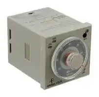
H3CRF8NAC2448DC1248
Analogue Timer, 8-Pin, IP40, H3CR-F Series, Flicker On Start, 24 Ranges, 0.05 s, 300 h
⚠️ Reference pricing provided. In case of supply shortages, we will connect you with our trusted procurement partners to ensure your project's continuity.
- Manufacturer: OMRON / PARTNER STOCK
- Product type: Analogue Timers
- SVHC: To Be Advised
- Time Max: 300h
- Time Min: 0.05s
- Timer Output: 2 Changeover Relays
- Product Range: H3CR-F Series
- Timer Functions: Flicker On Start
- Current Rating Nom: 5A
- Panel Cutout Width: 45mm
- Supply Voltage Max: 48V
- Panel Cutout Height: 45mm
- No. of Timing Ranges: 24Ranges
- Connection / Termination: Plug-In
| Delivery and price | |
|---|---|
| Units per pack | 3 |
| Price | 280.7 € |
| Current stock | 10+ |
| Lead time | 30 days |
Datasheet

## **Solid-state Timer H3CR** Please read and understand this catalog before purchasing the products. Please consult your OMRON representative if you have any questions or comments. Refer to Warranty and Application Considerations (page 52), and Safety Precautions (page 22, 44, 51). ## **DIN 48** ✕ **48-mm Multifunctional Timer Series** - Conforms to EN61812-1 and IEC60664-1 4 kV/2 for Low Voltage, and EMC Directives. - Lloyds/NK approvals. • Six-language instruction manual provided. - Approved by UL and CSA. ## ■ **Broad Line-up of H3CR Series** ## **H3CR** — **==> picture [475 x 222] intentionally omitted <==** **----- Start of picture text -----**<br> H3CR-A H3CR-F H3CR-G H3CR-H<br>Multifunctional Timer Twin Timer Star-delta Timer Power OFF-delay Timer<br>H3CR-A H3CR-F H3CR-G8L H3CR-HRL 11-pin model<br>11-pin model 8-pin model<br>H3CR-AS 11-pin model H3CR-FN H3CR-G8EL H3CR-H8L<br>8-pin model<br>H3CR-AP H3CR-F8 H3CR-H8RL<br>8-pin model<br>H3CR-A8 H3CR-F8N<br>8-pin model<br>H3CR-A8S<br>H3CR-A8E 8-pin with<br>instantaneous<br>contact output<br>model<br>**----- End of picture text -----**<br> **Note:** H3CR-AS, H3CR-A8S: Transistor output models ## Contents ## **Solid-state Timer** |**Solid-state Timer**|| |---|---| |H3CR-A ..........................................................................................................................................|2| |H3CR-F...........................................................................................................................................|26| |H3CR-G..........................................................................................................................................|34| |H3CR-H ..........................................................................................................................................|42| |**Common to ALL Timers**|| |Operation........................................................................................................................................|52| |Accessories ....................................................................................................................................|54| |Safety Precautions..........................................................................................................................|58| **1** **Solid-state Multi-functional Timers H3CR-A** ## **Multiple Operating Modes and Multiple Time Ranges. DIN 48 x 48-mm Multifunctional Timer.** - A wide AC/DC power supply range greatly reduces the number of timer models kept in stock. - A wide range of applications with multiple operating modes, eight modes for 11-pin models and five modes for 8-pin models. - Ecological design with reduced current consumption. - Easy sequence checking with instantaneous outputs for a zero set value. - Length of 75 mm or less when panel-mounted with a P3G-08 Socket (H3CR-A8E, 100 to 240 VAC, 100 to 125 VDC) For the most recent information on models that have been certified for safety standards, refer to your OMRON website. - PNP input models available. - Standards: UL, CSA, NK, LR, CCC, EN 61812-1, and CE Marking. ## **Model Number Structure** ## ■ **Model Number Legend** - **Note:** This model number legend includes combinations that are not available. Before ordering, please check the _List of Models_ on page 3 for availability. **H3CR-A** @ @ @ **-** @ @ **1 2 3 4 5** ## **1. Number of Pins** None: 11-pin models - 8: 8-pin models ## **2. Input Type for 11-pin Models** None: No-voltage input (NPN type) - P: Voltage input (PNP type) ## **3. Output** None: Relay output (DPDT) - S: Transistor output (NPN/PNP universal use) - E: Relay output (SPDT) with instantaneous relay output (SPDT) ## **4. Suffix** - 301: Double time scale (range) models (0.1 s to 600 h) ## **5. Supply Voltage** 100-240AC/100-125DC: 100 to 240 VAC/100 to 125 VDC 24-48AC/12-48DC: 24 to 48 VAC/12 to 48 VDC - 24-48AC/DC: 24 to 48 VAC/VDC (Only for H3CR-A8E) **2** **H3CR-A Orderin Information g** ## ■ **List of Models** **Note:** 1. Specify both the model number and supply voltage when ordering. Example: H3CR-A 100-240AC/100-125DC Supply voltage 2. The operating modes are as follows A: ON-delay D: Signal OFF-delay B: Flicker OFF start E: Interval B2: Flicker ON start G: Signal ON/OFF-delay C: Signal ON/OFF-delay J: One-shot ## **11-pin Models** |**11-pin Models**|||||| |---|---|---|---|---|---| |**Output**|**Supply voltage**|**Input type**|**Time range**|**Operating mode**<br>**(See note 2)**|**Model**<br>**(See note 1.)**| |**Contact**|100 to 240 VAC (50/60 Hz)/<br>100 to 125 VDC|No-voltage input|0.05 s to 300 h|Eight multi-modes: A, B,<br>B2, C, D, E, G, J|<br>H3CR-A| ||24 to 48 VAC (50/60 Hz)/<br>12 to 48 VDC||||| ||100 to 240 VAC (50/60 Hz)/<br>100 to 125 VDC|Voltage input||Eight multi-modes: A, B,<br>B2, C, D, E, G, J|<br>H3CR-AP| ||24 to 48 VAC (50/60 Hz)/<br>12 to 48 VDC||||| ||100 to 240 VAC (50/60 Hz)/<br>100 to 125 VDC|No-voltage input|0.1 s to 600 h||H3CR-A-301| ||24 to 48 VAC (50/60 Hz)/<br>12 to 48 VDC||||| |**Transistor**<br>**(Photocoupler)**|24 to 48 VAC (50/60 Hz)/<br>12 to 48 VDC||0.05 s to 300 h||H3CR-AS| ## **8-pin Models** |**8-pin Models**|||||| |---|---|---|---|---|---| |**Output**|**Supply voltage**|**Input type**|**Time range**|**Operating mode**<br>**(See note 2)**|**Model**<br>**(See note 1.)**| |**Contact**|100 to 240 VAC (50/60 Hz)/<br>100 to 125 VDC|No-input available|0.05 s to 300 h|Five multi-modes: A, B,<br>B2, E, J<br>(Power supply start)|H3CR-A8| ||24 to 48 VAC (50/60 Hz)/<br>12 to 48 VDC||||| ||100 to 240 VAC (50/60 Hz)/<br>100 to 125 VDC||0.1 s to 600 h||H3CR-A8-301| ||24 to 48 VAC (50/60 Hz)/<br>12 to 48 VDC||||| |**Transistor**<br>**(Photocoupler)**|24 to 48 VAC (50/60 Hz)/<br>12 to 48 VDC||0.05 s to 300 h||H3CR-A8S| |**Time-limit contact and**<br>**instantaneous contact**|100 to 240 VAC (50/60 Hz)/<br>100 to 125 VDC||||H3CR-A8E| ||24 to 48 VAC/VDC(50/60 Hz)||||| **==> picture [540 x 35] intentionally omitted <==** **3** **H3CR-A** ## ■ **Accessories (Order Separately)** ## **Adapter, Protective Cover, Hold down Clip, Setting Ring and Panel Cover** |**Name/specifications**|**Name/specifications**|**Models**| |---|---|---| |**Flush Mounting Adapter**||Y92F-30| |||Y92F-73*1| |||Y92F-74*1| |**Protective Cover**||Y92A-48B*2| |**Hold-down Clip (Sold in sets of**<br>**two)**|**For PF085A Socket**|Y92H-8| ||**For PL08 or PL11 Sockets**|Y92H-7| |**Setting Ring A**||Y92S-27*3| |**Setting Ring B and C**||Y92S-28*3| |**Panel Cover**|**Lightgray (5Y7/1)**|Y92P-48GL*4| ||**Black (N1.5)**|Y92P-48GB*4| - *1 The Y92A-48B Protective Cover and the Y92P-48G @ Panel Cover can not be used at the same time with the Y92F-73/-74 Flush Mounting Adapter. - *2 The Y92A-48B Protective Cover is made from hard plastic. Remove the Protective Cover to change to set value. The Y92F-73/-74 Flush Mounting Adapter and the Y92P-48G @ Panel Cover cannot be used at the same time with Y92A-48B Protective Cover. - *3 The Y92S-27/-28 Setting Ring cannot be used alone. It must be used together with the Y92P-48G @ Panel Cover. - *4 The Y92A-48B Protective Cover and the Y92F-73/-74 Flush Mounting Adapter cannot be used at the same time with the Y92P-48G @ Panel Cover. ## **Sockets** |**Sockets**|||| |---|---|---|---| |**Timer**||**Round Sockets**|| |**Pin**|**Connection**|**Terminal**|**Models**| |11-pin|Front Connecting|DIN track mounting|**P2CF-11**| |||DIN track mounting<br>(Finger-safe type)|**P2CF-11-E**| ||Back Connecting|Screw terminal|**P3GA-11**| |||Solder terminal|**PL11**| |||Wrappingterminal|**PL11-Q**| |||PCB terminal|**PLE11-0**| |8-pin|Front Connecting|DIN track mounting|**P2CF-08**| |||DIN track mounting<br>(Finger-safe type)|**P2CF-08-E**| |||DIN track mounting|**PF085A**| ||Back Connecting|Screw terminal|**P3G-08**| |||Solder terminal|**PL08**| |||Wrappingterminal|**PL08-Q**| |||PCB terminal|**PLE08-0**| - **Note: 1.** The P2CF- @@ -E has a finger-protection structure. Round crimp terminals cannot be used. Use forked crimp terminals. **2.** The P3GA-11 and P3G-08 Socket can be used together with the Y92A-48G Terminal Cover to implement finger protection. **3.** For details, refer to your OMRON website. ## **Terminal Cover** |**Terminal Cover**||| |---|---|---| |**Application**|**Model**|**Remarks**| |**For back connecting socket**|**Y92A-48G**|For P3G-08 and P3GA-11| **Note:** For details, refer to your OMRON website. **==> picture [539 x 35] intentionally omitted <==** **4** **H3CR-A** ## **S ecifications p** ## ■ **General** |■**General**||||| |---|---|---|---|---| |**Item**|**H3CR-A/-AS/-A-301**|**H3CR-AP**|**H3CR-A8/-A8S/-A8-301**|**H3CR-A8E**| |**Operating mode**|A:<br>ON-delay<br>B:<br>Flicker OFF start<br>B2: Flicker ON start<br>C: Signal ON/OFF-delay<br>D: Signal OFF-delay<br>E:<br>Interval<br>G: Signal ON/OFF-delay<br>J:<br>One-shot||A:<br>ON-delay (power supply start)<br>B: Flicker OFF start (power supply start)<br>B2: Flicker ON start (power supply start)<br>E:<br>Interval (power supply start)<br>J:<br>One-shot (power supply start)|| |**Pin type**|11-pin||8-pin|| |**Input type**|No-voltage input|Voltage input|---|| |**Time-limit output type**|H3CR-A/-A8/-AP/-A-301/-A8-301: Relay output (DPDT)<br>H3CR-AS/-A8S:<br>Transistor output (NPN/PNP universal)*|||Relay output (SPDT)| |**Instantaneous output type**|---|||Relay output (SPDT)| |**Mounting method**|DIN track mounting, surface mounting, and flush mounting|||| |**Approved standards**|UL508, CSA C22.2 No.14, NK, Lloyds, CCC<br>Conforms to EN61812-1 and IEC60664-1 (VDE0110) 4kV/2.<br>Output category according to EN60947-5-1 for Timers with Contact Outputs.<br>Output category according to EN60947-5-2 for Timers with Transistor Outputs.|||| * The internal circuits are optically isolated from the output. This enables universal application as NPN or PNP transistor. For details, refer to your OMRON website. ## ■ **Time Ranges** **Note:** When the time setting knob is turned below “0” until the point where the time setting knob stops, the output will operate instantaneously at all time range settings. For details, refer to your OMRON website. ## **Standard (0.05-s to 300-h) Models** |**Time unit**|**Time unit**|**s (sec)**|**10 s (10 sec)**|**min (min)**|**10 min (10 min)**|**h (hrs)**|**10 h (10 hrs)**| |---|---|---|---|---|---|---|---| |**Full scale**<br>**setting**|1.2|0.05 to 1.2|1.2 to 12|0.12 to 1.2|1.2 to 12|0.12 to 1.2|1.2 to 12| ||3|0.3 to 3|3 to 30|0.3 to 3|3 to 30|0.3 to 3|3 to 30| ||12|1.2 to 12|12 to 120|1.2 to 12|12 to 120|1.2 to 12|12 to 120| ||30|3 to 30|30 to 300|3 to 30|30 to 300|3 to 30|30 to 300| ## **Double (0.1-s to 600-h) Models** |**Time unit**|**Time unit**|**s (sec)**|**10 s (10 sec)**|**min (min)**|**10 min (10 min)**|**h (hrs)**|**10 h (10 hrs)**| |---|---|---|---|---|---|---|---| |**Full scale**<br>**setting**|2.4|0.1 to 2.4|2.4 to 24|0.24 to 2.4|2.4 to 24|0.24 to 2.4|2.4 to 24| ||6|0.6 to 6|6 to 60|0.6 to 6|6 to 60|0.6 to 6|6 to 60| ||24|2.4 to 24|24 to 240|2.4 to 24|24 to 240|2.4 to 24|24 to 240| ||60|6 to 60|60 to 600|6 to 60|60 to 600|6 to 60|60 to 600| **==> picture [540 x 35] intentionally omitted <==** **5** **H3CR-A** ## ■ **Ratings** |■**Ratings**||| |---|---|---| |**Rated supply voltage (See notes 1, 2, and 5.)**|100 to 240 VAC (50/60 Hz)/100 to 125 VDC, 24 to 48 VAC (50/60 Hz)/12 to 48 VDC (24 to 48 VAC/VDC for H3CR-A8E)<br>(See note 3.)|| |**Operating voltage range**|85% to 110% of rated supply voltage (90% to 110% at 12 VDC)|| |**Power reset**|Minimum power-opening time: 0.1 s|| |**Input (See note 6.)**|No-voltage Input<br>ON impedance:<br>1 kΩmax.<br>ON residual voltage:<br>1 V max.<br>OFF impedance:<br>100 kΩmin.<br>Voltage Input<br>Max. permissible capacitance between inputs lines (terminals 6 and 7): 1,200 pF<br>Load connectable in parallel with inputs (terminals 6 and 7).<br>• 100 to 240 VAC/100 to 125 VDC<br>High (logic) level:<br>85 to 264 VAC/85 to 137.5 VDC<br>Low (logic) level:<br>0 to 10 VAC/0 to 10 VDC<br>• 24 to 48 VAC/12 to 48 VDC<br>High (logic) level:<br>20.4 to 52.8 VAC/10.8 to 52.8 VDC<br>Low (logic) level:<br>0 to 2.4 VAC/0 to 1.2 VDC|| |**Power consumption**|H3CR-A/-A8<br>• 100 to 240 VAC/100 to 125 VDC<br>(When at 240 VAC, 60 Hz)<br>Relay ON: approx. 2.0 VA (1.6 W)<br>Relay OFF: approx. 1.3 VA (1.1 W)<br>• 24 to 48 VAC/12 to 48 VDC<br>(When at 24 VDC)<br>Relay ON: approx. 0.8 W<br>Relay OFF: approx. 0.2 W<br>H3CR-AP<br> (See note 3)<br>• 100 to 240 VAC/100 to 125 VDC<br>(When at 240 VAC, 60 Hz)<br>Relay ON: approx. 2.5 VA (2.2 W) (See note 4.)<br>Relay OFF: approx. 1.8 VA (1.7 W) (See note 4.)<br>• 24 to 48 VAC/12 to 48 VDC<br>(When at 24 VDC)<br>Relay ON: approx. 0.9 W (See note 4.)<br>Relay OFF: approx. 0.3 W (See note 4.)<br>H3CR-A8E<br>• 100 to 240 VAC/100 to 125 VDC<br>(When at 240 VAC, 60 Hz)<br>Relay ON/OFF: approx. 2 VA (0.9 W)<br>• 24 to 48 VAC/VDC<br>(When at 24 VDC)<br>Relay ON/OFF: approx. 0.9 W<br>H3CR-AS/-A8S<br>• 24 to 48 VAC/12 to 48 VDC<br>(When at 24 VDC)<br>Output ON: 0.3 W Output OFF: 0.2 W|| ||•|| |**Control outputs**|• <br>•|Models with Contact Outputs<br>H3CR-A/-A8/-AP<br>5A at 250 VAC/30 VDC, 0.15A at 125 VDC, resistive load (cosφ= 1)<br>Minimum applied load: 10mA at 5 VDC (failure level: P reference value)<br>Contact materials: Ag-alloy<br>H3CR-A8E<br>5A at 250 VAC/30 VDC, 0.15A at 125 VDC, resistive load (cosφ= 1)<br>Minimum applied load: 10mA at 5 VDC (failure level: P reference value)<br>Contact materials: AgSnIn<br> Transistor output: Open collector(NPN/PNP)<br>H3CR-AS/-A8S<br>100 mA max at 30 VDC max., residual voltage: 2 VDC max.| ## **Note: 1.** DC ripple rate: 20% max. (A single-phase, full-wave-rectification power supply can be used). **2.** Do not use an inverter output as the power supply. Refer to your OMRON website for details. **3.** Models with 24-to-48-VAC or 12-to-48-VDC power supply have inrush current. Caution is thus required when turning ON and OFF power to the Timer with a non-contact output from a device such as a sensor. (Models with an inrush current of approximately 50 mA and a 24VDC power supply are available (the H3CR-A-302 and H3CR-A8-302).) - For details, consult your OMRON sales representative. **4.** The values are for when the terminals 2 and 7 and terminals 10 and 6 are short-circuited, and include the consumption current of the input circuit. **5.** Refer to your OMRON website when using the Timer together with a 2-wire AC proximity sensor. **6.** For details, see _Input Connections: No-voltage Input Signal Levels_ on page 11, and _Input Connections: Voltage Input Signal Levels_ on page 12. **==> picture [539 x 34] intentionally omitted <==** **6** **H3CR-A** ## ■ **Characteristics** |**Accuracy of operating**<br>**time**|±0.2% FS max. (±0.2%±10 ms max. in a range of 1.2 s or 3 s)| |---|---| |**Setting error**|±5% FS±50 ms(See note 1)| |**Reset time**|Min. power-opening time: 0.1 s max.<br>Min.pulse width:<br>0.05 s(H3CR-A/-AS)| |**Reset voltage**|10% max. of rated supplyvoltage| |**Influence of voltage**|±0.2% FS max.(±0.2%±10 ms max. in a range of 1.2 s or 3 s)| |**Influence of temperature**|±1% FS max.(±1%±10 ms max. in a range of 1.2 s or 3 s)| |**Insulation resistance**|100 MΩmin.(at 500 VDC)| |**Dielectric strength**|2,000 VAC (1,000 VAC for H3CR-A@S), 50/60 Hz for 1 min (between current-carrying metal parts and exposed non-<br>current-carrying metal parts)<br>2,000 VAC (1,000 VAC for H3CR-A@S), 50/60 Hz for 1 min (between control output terminals and operating circuit)<br>2,000 VAC, 50/60 Hz for 1 min (between contacts of different polarities)<br>1,000 VAC, 50/60 Hz for 1 min (between contacts not located next to each other)<br>2,000 VAC, 50/60 Hz for 1 min(between input and control output terminals and operation circuit)for H3CR-AP| |**Impulse withstand**<br>**voltage**|5 kV (between power terminals) for 100 to 240 VAC/100 to 125 VDC, 1 kV for 24 to 48 VAC/12 to 48 VDC<br>5 kV (between current-carrying terminal and exposed non-current-carrying metal parts) for 100 to 240 VAC/100 to<br>125 VDC, 1.5 kV for 24 to 48 VAC/12 to 48 VDC and 24 to 48 VAC/VDC| |**Noise immunity**|±1.5 kV (between power terminals) and±600 V (between no-voltage input terminals), square-wave noise by noise<br>simulator(pulse width: 100 ns/1μs, 1-ns rise)| |**Static immunity**|Malfunction: 8 kV<br>Destruction: 15 kV| |**Vibration resistance**|Destruction: 10 to 55 Hz with 0.75-mm single amplitude each in 3 directions for 2 hours each<br>Malfunction: 10 to 55 Hz with 0.5-mm single amplitude each in 3 directions for 10 minutes each| |**Shock resistance**|Destruction: 1,000 m/s23 times each in 6 directions<br>Malfunction: 100 m/s23 times each in 6 directions| |**Ambient temperature**|Operating:<br>−10°C to 55°C (with no icing)<br>Storage:<br>−25°C to 65°C(with no icing)| |**Ambient humidity**|Operating:<br>35% to 85%| |**Life expectancy**|Mechanical: 20,000,000 operations min. (under no load at 1,800 operations/h)<br>Electrical:<br>100,000 operations min.(5 A at 250 VAC, resistive load at 1,800 operations/h) (See note 2)| |**EMC**|(EMI)<br>EN61812-1<br>Emission Enclosure:<br>EN55011 Group 1 class A<br>Emission AC Mains:<br>EN55011 Group 1 class A<br>(EMS)<br>EN61812-1<br>Immunity ESD:<br>IEC61000-4-2<br>Immunity RF-interference:<br>IEC61000-4-3<br>Immunity Burst:<br>IEC61000-4-4<br>Immunity Surge:<br>IEC61000-4-5<br>Immunity Conducted Disturbance:<br>IEC61000-4-6<br>ImmunityVoltage Dip/Interruption:<br>IEC61000-4-11| |**Case color**|Lightgray (Munsell 5Y7/1)| |**Degree ofprotection**|IP40(panel surface)| |**Weight**|Approx. 90g| - **Note: 1.** The value is ±5% FS +100 ms to −0 ms max. when the C, D, or G mode signal of the H3CR-AP is OFF. **2.** Refer to the _Life-test Curve (Reference)_ . **3.** Contact output only. ## ■ **Life-test Curve (Reference)** **==> picture [134 x 118] intentionally omitted <==** **----- Start of picture text -----**<br> 10,000<br>5,000 fo——<br>1,000<br>30 VDC L/R = 7 ms<br>500<br>250 VAC/30<br>PANS VDC (cosφ = 1)<br>100 Nee<br>250 VAC (cosφ = 0.4)<br>0 1 2 3 4 5<br>Load current (A)<br>3)<br>Switching operations (x 10<br>**----- End of picture text -----**<br> Reference: A maximum current of 0.15 A can be switched at 125 VDC (cosφ = 1) and a maximum current of 0.1A can be switched at 125V DC and L/R = 7ms. In both cases, a life of 100,000 operations can be expected. The minimum applicable load is 10 mA at 5 VDC (failure level: P). **7** **H3CR-A** ## **Connections** ## ■ **Block Diagrams** ## **H3CR-A/-AS/-A-301** ## **H3CR-AP** **==> picture [336 x 414] intentionally omitted <==** **----- Start of picture text -----**<br> Zero setting<br>AC (DC) input detection Time range/ Operating<br>unit selectors mode selector<br>circuit<br>Power supply Oscillation Counting<br>circuit circuit circuit Output circuit<br>Reset input, start input, and gate input Input circuit Indicator<br>circuit<br>Power-ON Output-ON<br>indicator indicator<br>Zero setting<br>AC (DC) input detection Time range/ Operating<br>unit selectors mode selector<br>circuit<br>Power supply Oscillation Counting<br>circuit circuit circuit Output circuit<br>Indicator<br>Start Input circuit<br>circuit<br>Power-ON Output-ON<br>indicator indicator<br>**----- End of picture text -----**<br> **==> picture [539 x 35] intentionally omitted <==** **8** **H3CR-A** **H3CR-A8/-A8S/A8-301** **==> picture [437 x 449] intentionally omitted <==** **----- Start of picture text -----**<br> Zero setting<br>AC (DC) input detection Time range/ Operating<br>unit selectors mode selector<br>circuit<br>Power supply Oscillation Counting<br>circuit circuit circuit Output circuit<br>Indicator<br>circuit<br>Power-ON Output-ON<br>indicator indicator<br>H3CR-A8E<br>Zero setting<br>AC (DC) input detection Time range/ Operating<br>unit selectors mode selector<br>circuit<br>Power supply Oscillation Counting<br>circuit circuit circuit Output circuit<br>Indicator<br>circuit<br>Power-ON Output-ON<br>indicator indicator<br>Instantaneous<br>output circuit<br>**----- End of picture text -----**<br> ## ■ **I/O Functions** |**Inputs (for -A/**<br>**-AS models)**|**Start**|Starts time-measurement.| |---|---|---| ||**Reset**|Interrupts time-measurement and resets time-measurement value. Timing operation is stopped and the<br>control output turns OFF(it is reset).| ||**Gate**|The timingoperation is interrupted while thegate input is active.| |**Outputs**|**Control output**|Outputs are turned ON according to designated output mode when preset value is reached.| **Note:** H3CR-AP incorporates start input only. Models H3CR-A8/-A8E/-A8S/-A8-301 do not have an input function. **==> picture [540 x 35] intentionally omitted <==** **9** **H3CR-A** ## ■ **Terminal Arrangement** **Note: 1.** The delayed contact of conventional Timers was indicated as The contact symbol of the H3CR-A is indicated as because its operating mode is six multi-modes (four multi-modes for the H3CR-A8). **2.** Do not use an empty terminal on the H3CR-AP/-AS/-A8S as a relay terminal or otherwise. ## **11-pin Models** ## **8-pin Models** **==> picture [191 x 146] intentionally omitted <==** **----- Start of picture text -----**<br> H3CR-A/-A-301 (Contact Output)<br>i. 3 3 | ~ u -<br>6 [le<br>jC PS<br>(-(-) Na Na Power supply<br>Reset input Start input Gate input<br>**----- End of picture text -----**<br> **==> picture [507 x 305] intentionally omitted <==** **----- Start of picture text -----**<br> H3CR-A/-A-301 (Contact Output) H3CR-A8/-A8-301 (Contact Output)<br>Reser a)<br>3 3 | ~ u - | 4 2 7 | |<br>6 [le Bad ' x: Power supply a | ia<br>jC PS | -_<br>(-(-) Na Na Power supply H3CR-A8S (Transistor Output)<br>i oo Lg _<br>H3CR-AS (Transistor Output)<br>| (°° |<br>it eo<br>eorn | eee!<br>| : e e L. —<br>o©@ Power supply<br>2<br>1 CH | Note: Terminals 1, 3, 4, and 5 are empty. Terminals 2 and 7 are the<br>; oa x , same as for the H3CR-A8.<br>H3CR-A8E (Contact Output)<br>Ct) Yo Power supply PHI) oo Lt Lt<br>Reset input Start input Gate input<br>Reset input Start input Gate input<br>**----- End of picture text -----**<br> **H3CR-AS (Transistor Output)** **==> picture [173 x 126] intentionally omitted <==** **----- Start of picture text -----**<br> H3CR-A8E (Contact Output)<br>oo Lt Lt<br>\2 2 . ?<br>Power supply<br>——<br>**----- End of picture text -----**<br> **Note:** Terminals 1, 3, 4, and 8 are empty. Terminals 2, 5, 6, 7, and 10 are the same as for the H3CR-A. ## **H3CR-AP (Contact Output)** 06: Or) 4G Power supply B®) **Note: 1.** Terminal 5 is empty. **2.** Separate power supplies can be used for the Timer and inputs. **10** **H3CR-A** ## ■ **Input Connections** ## **H3CR-A/-AS/-A-301** The inputs of the H3CR-A/-AS/-A-301 are no-voltage (short-circuit or open) inputs. ## **No-voltage Inputs** **==> picture [420 x 284] intentionally omitted <==** **----- Start of picture text -----**<br> No-contact Input Contact Input No-contact Input<br>(Connection to NPN open (Connection to a voltage<br>collector output sensor.) output sensor.)<br>12 to 24 VDC 12 to 24 VDC<br>(sensor power supply) (sensor power supply)<br>+ − DC power supply + − DC power supply<br>Timer Timer Timer<br>Sensor<br>Sensor<br>5 Gate 5 Gate 5 Gate<br>6 Start 6 Start 6 Start<br>7 Reset 7 Reset 7 Reset<br>2 Input (0 V) 2 Input (0 V) 2 Input (0 V)<br>Operates with transistor ON Operates with relay ON Operates with transistor ON<br>No-voltage Input Signal Levels<br>No-contact 1. Short-circuit level<br>input Transistor ON<br>Residual voltage: 1 V max.<br>Impedance when ON: 1 k Ω max.<br>2. Open level<br>Transistor OFF<br>Impedance when OFF: 100 k Ω min.<br>Contact Use contacts which can<br>input adequately switch 0.1 mA at 5 V<br>**----- End of picture text -----**<br> **==> picture [540 x 35] intentionally omitted <==** **11** **H3CR-A** ## **H3CR-AP** The start input of the H3CR-AP is voltage input. (Voltage imposition or open) **==> picture [456 x 172] intentionally omitted <==** **----- Start of picture text -----**<br> Voltage Inputs<br>No-contact Input No-contact Input Contact Input<br>(Connection to PNP open (Connection to NPN open<br>collector output sensor) collector output sensor)<br>12 to 24 VDC 12 to 24 VDC<br>(sensor power supply) (sensor power supply)<br>+ DC power + DC power<br>− supply − supply<br>Sensor Sensor<br>Timer Timer<br>Timer<br>10 Power supply (+) 10 Power supply (+) 10 Power supply (+)<br>6 Start 6 Start 6 Start<br>7 Input 0V 7 Input 0V 7 Input 0V<br>2 Power supply 2 Power supply ( − ) 2 Power supply ( − )<br>( − )<br>Operates with PNP transistor ON Operates with NPN transistor ON Operates with relay ON<br>AC power supply DC power supply<br>**----- End of picture text -----**<br> **Note:** The input circuit is isolated from the **Note:** Refer to the signal levels in the power supply circuit. Thus, an NPN following table and be aware of the transistor can be connected. minimum applicable load of the relay. **Note:** Before making connections, refer to _Safety Precautions (H3CR-_ @ _)_ . ## **Voltage Input Signal Levels** |No-contact<br>input|1. Transistor ON<br>Residual voltage: 1 V max.<br>The voltage between terminals 6 and 7 must be 10.8 VDC min.| |---|---| ||2. Transistor OFF<br>Leakage current: 0.01 mA max.<br>The voltage between terminals 6 and 7 must be 1.2 VDC max.| |Contact<br>input|Use contacts that can adequately switch 0.1 mA at each<br>operating voltage.<br>The voltage between terminals 6 and 7 with contacts ON or<br>OFF must satisfy the specified value.<br>Contacts ON<br>100-to-240-VAC and 100-to-125-VDC models: 85 to 264 VAC<br>or 85 to 137.5 VDC<br>24-to-48-VAC and 12-to-48-VDC models: 20.4 to 52.8 VAC or<br>10.8 to 52.8 VDC<br>Contacts OFF<br>100-to-240-VAC and 100-to-125-VDC models: 0 to 10 VAC or<br>0 to 10 VDC<br>24-to-48-VAC and 12-to-48-VDC models: 0 to 2.4 VAC or 0 to<br>1.2 VDC| **12** **H3CR-A O eration p** ## ■ **Timing Chart (Refer to page 20 for application examples.)** ## **H3CR-A/-AS/-AP*/-A-301** **==> picture [486 x 443] intentionally omitted <==** **----- Start of picture text -----**<br> Operating Timing chart<br>mode<br>A: ON-delay t t<br>Basic operation<br>Power<br>ie C______<br>Power<br>Start<br>Reset Start<br>ee ee ee (See note) i t<br>Output relay (NC)<br>nena rc Output ee Seee<br>Output relay (NO)<br>(Output indicator) Note: Start input is invalid while the<br>Power indicator Timer is in operation.<br>B:Flicker OFF 1 t ix t t if Basic operation<br>Power<br>start Power<br>Start ao | || bal | 1 ares [eS]<br>Reset Start<br>a i aa |_| (See note) t t t t<br>Output relay (NC)<br>Output<br>Output relay (NO)<br>(Output indicator) Note: Start input is invalid while<br>Power indicator the Timer is in operation.<br>B2: t 1S t t t<br>Flicker ON Basic operation<br>start Power<br>Power<br>Start<br>Reset Start<br>Output relay (NC) (See note) t t t t<br>Sn ee =.<br>Output<br>Output relay (NO) Se 2<br>(Output indicator) Note: Start input is invalid while the<br>Power indicator Timer is in operation.<br>C:<br>1 t 8 jt nee a t<br>Signal ON/ Basic operation<br>OFF-delay Power ee on eo omen<br>Power<br>Start pee ee es be<br>Reset ee Start<br>ee (See note) t t t t<br>Output relay (NC) Output<br>Output relay (NO) (Output indicator) Note: Start input is valid and<br>Power indicator retriggerable while the Timer<br>is in operation.<br>**----- End of picture text -----**<br> **Note: 1.** Allow at least 0.1 s for the Timer reset time if the power supply is reset due to an interruption in the power supply. **2.** The minimum input pulse width (for start, reset) is 0.05 s. **3.** The letter "t" in the timing charts indicates the set time, and "t-a" means that the period is less than the set time. (t - a < 1) **4.** H3CR-AP model incorporates start input only. **5.** Model H3CR-AS only has operation equivalent to time-limit contact: NO. **6.** When the setting dial is turned all the way past 0 for instantaneous output, "t" (set time) in the above time chart is 0-sec operation. **13** **H3CR-A** **==> picture [476 x 502] intentionally omitted <==** **----- Start of picture text -----**<br> Operating Timing chart<br>mode<br>D:Signal OFF- t ia t—a t ta Basic operation<br>delay Power<br>Start Power<br>Reset Start<br>ee (See note) — t<br>Output relay (NC)<br>oa ~ - Output enail<br>Output relay (NO)<br>(Output indicator) Note: Start input is valid and<br>Power indicator retriggerable while the<br>Timer is in operation.<br>E: Interval ||t-a Lt—a Basic operation<br>Power<br>Power<br>Start<br>Start<br>Reset (See note) t<br>Output relay (NC) Output<br>re eeee | | |<br>Output relay (NO) Note: Start input is valid and<br>(Output indicator)<br>retriggerable while the<br>Power indicator Timer is in operation.<br>(Previous start input<br>will be cancelled.)<br>G:Signal ON/ bp Fet—a ta — Basic operation<br>OFF-delay Power ll<br>Power<br>Start<br>] z<br>Reset Start<br>(See note) t t t t<br>Output relay (NC)<br>Output<br>Output relay (NO) ee ee<br>(Output indicator) Note: Start input is valid and<br>Power indicator FLAIR ALO DR SAF G AEE ARP 2BAB retriggerable while the Timer<br>is in operation.<br>J: L l-a ima t<br>One-shot Basic operation<br>output Power eReeae<br>Start Power<br>Reset ea| | Start<br>Output relay (NC) (See note) t 1 ± 0.6 s<br>1 ± 0.6 s 1 ± 0.6 s Output (Fixed)<br>Output relay (NO) se: (Fixed) (Fixed)<br>(Output indicator) Note: Start input is valid and<br>Power indicator<br>retriggerable while the<br>Timer is in operation.<br>(Previous start input will<br>be cancelled.)<br>**----- End of picture text -----**<br> ## **Gate Signal Input (This timing chart indicates the gate input in operating mode A (ON-delay operation).)** **==> picture [132 x 118] intentionally omitted <==** **----- Start of picture text -----**<br> t1 a — t2<br>Power ON<br>OFF<br>Start ON<br>OFF a)<br>Gate ON<br>OFF<br>Reset ON<br>OFF<br>Output ON<br>relay OFF<br>**----- End of picture text -----**<br> - **Note: 1.** Allow at least 0.1 s for the Timer reset time if the power supply is reset due to an interruption in the power supply. **2.** The minimum input pulse width (for start, reset) is 0.05 s. **3.** The letter "t" in the timing charts indicates the set time, and "t-a" means that the period is less than the set time. (t - a < 1) **4.** In J Mode, there will be only one output even if the start input is longer than the set time. **5.** H3CR-AP model incorporates start input only. **6.** Model H3CR-AS only has operation equivalent to time-limit contact: NO. **7.** When the setting dial is turned all the way past 0 for intantaneous output, "t" (set time) in the above time chart is 0-sec operation. **Note:** The set time is the sum of t1 and t2. Start and reset are also both enabled when the gate signal is ON. **14** **H3CR-A** ## **H3CR-A8/-A8S/-A8-301** |**Operating**<br>**mode**|**Timing chart**| |---|---| |A:<br>ON-delay|t<br>Power<br>Output<br>Basic operation<br>Power<br>Output relay<br>(NC)<br>Output relay<br>(NO) (output<br>indicator)<br>Power<br>indicator<br>t<br>Rt<br>i<br>Rt<br>t—a<br>|<br>ae oe<br>~~—~~<br>|<br>noooowie<br>benoomee<br>6 AL| |B:<br>Flicker OFF<br>start|Power<br>Output<br>t<br>t<br>t<br>t<br>Power<br>Output relay<br>(NC)<br>Output relay<br>(NO) (output<br>indicator)<br>Power<br>indicator<br>t<br>t<br>t<br>t<br>t<br>Rt<br>t-a<br>t-a<br>Basic operation<br>~~YP~~<br>~~Ty~~<br>~~ee~~<br>CC)<br>~~| a~~<br>|<br>| ~~a~~<br>~~es~~<br>~~—~~<br>~~oe~~| |B2:<br>Flicker ON<br>start|v<br>t<br>t<br>t<br>t<br>Power<br>Power<br>Output<br>Basic operation<br>Output relay<br>(NC)<br>Output relay<br>(NO) (output<br>indicator)<br>Power<br>indicator<br>i-a<br>At<br>ta<br>t<br>t =<br>1<br>t<br>t<br>r<br>or<br>oo<br>~~Co~~| |E:<br>Interval|t<br>Power<br>Output<br>Basic operation<br>Power<br>Output relay<br>(NC)<br>Output relay<br>(NO) (output<br>indicator)<br>Power<br>indicator<br>Ri<br>Rt<br>t=—a<br>~——1!<br>—t<br>2<br>Ieee<br>bas<br>~~L~~e<br>PARRA<br>BARRA| |J:<br>One-shot<br>output|t<br>Power<br>Power<br>Output<br>Basic operation<br>Output relay<br>(NC)<br>Output relay<br>(NO) (output<br>indicator)<br>Power<br>indicator<br>1±0.6 s<br>(Fixed)<br>1±0.6 s<br>(Fixed)<br>1±0.6 s<br>(Fixed)<br>Rt<br>t-a<br>Rt<br>—| - **Note: 1.** Allow a timer reset time (Rt) of 0.1 s or longer. **2.** The letter "t" in the timing charts indicates the set time, and "t-a" means that the period is less than the set time. (t - a < 1) **3.** Model H3CR-A8S only has operation equivalent to time-limit contact: NO. **4.** When the setting dial is turned all the way past 0 for intantaneous output, "t" (set time) in the above time chart is 0-sec operation. **5.** You can use J Mode to use the power supply as the start input. **15** **H3CR-A** ## **H3CR-A8E** |**Operating**<br>**mode**|**Timing chart**| |---|---| |A:<br>ON-delay|t<br>Power<br>Power indicator<br>Power<br>Output<br>Basic operation<br>Output relay (NC)<br>Output relay (NO)<br>(output indicator)<br>Instantaneous<br>output relay (NC)<br>Instantaneous<br>output relay (NO)<br>t<br>Rt<br>t<br>Rt<br>t—a<br>a<br>=<br>|<br>~~—~~<br>~~|~~<br>|<br>|<br>|<br>|<br>———$———<br>|<br>|<br>|<br>[a<br>me<br>es<br>2<br>ad| |B:<br>Flicker OFF<br>start|t<br>t<br>t<br>t<br>t<br>t<br>t<br>t<br>t<br>Rt<br>t-a<br>t-a<br>Power<br>Power indicator<br>Basic operation<br>Output relay (NC)<br>Output relay (NO)<br>(output indicator)<br>Instantaneous<br>output relay (NC)<br>Instantaneous<br>output relay (NO)<br>Power<br>Output<br>eae<br>_<br>~~| LE~~<br>| ~~a~~<br>|<br>|] ~~>~~<br>~~fs~~<br>~~|~~<br>|<br>|<br>~~be~~<br>| hf<br>~~——~~| |B2:<br>Flicker ON<br>start|t<br>t<br>t<br>t<br>Power<br>Power indicator<br>Power<br>Output<br>Basic operation<br>Output relay (NC)<br>Output relay (NO)<br>(output indicator)<br>Instantaneous<br>output relay (NC)<br>Instantaneous<br>output relay (NO)<br>ta<br>Rt<br>t-a<br>a<br>ns<br>DO<br>LO<br>| a<br>az<br>|.<br>|<br>|_| a| |E:<br>Interval|t<br>Power<br>Output<br>Basic operation<br>Power<br>Power indicator<br>Output relay (NC)<br>Output relay (NO)<br>(output indicator)<br>Instantaneous<br>output relay (NC)<br>Instantaneous<br>output relay (NO)<br>Rt<br>Rit<br>t—a<br>ee<br>aes<br>Eee<br>=<br>Eee ~~|~~<br>“ee<br>eee<br>ea<br>aaneEE—<br>5<br>Z<br>PAGO RMI<br>BARBAE<br>6<br>—_—_—| |J:<br>One-shot<br>output|t<br>Power<br>Power indicator<br>Power<br>Output<br>Basic operation<br>(Fixed)<br>(Fixed)<br>Output relay (NC)<br>Output relay (NO)<br>(output indicator)<br>Instantaneous<br>output relay (NC)<br>Instantaneous<br>output relay (NO)<br>1±0.6 s<br>(Fixed)<br>Rt<br>ta<br>Rt<br>—<br>ie<br>pono<br>loon! leno ou<br>—__—____| **Note:** Refer to page 14. **16** **H3CR-A Nomenclature** Power indicator (green) (Flashes when Timer operates; lit when Timer stops operating) Operating mode display window Operating mode selector Select a mode from: A, B, B2, C, D, E, G, and J (H3CR-A, -AP, and -AS) A, B, B2, E and J (H3CR-A8, -A8S, and -A8E) Output indicator (orange) (Lit when output) 40 20 5© a) ~~30~~ Time range selector (select one Q from 1.2, 3, 12, and 30 at full Lamon H3cR min scale; with the H3CR-A @ -301, select from 2.4, 6, 24, or 60 at Time setting full scale.) knob (set time) Scale range display windows Time unit display window Time unit selector (select one from sec, 10s, min, 10m, hrs, and 10h) Scale range display windows changes as below by turning the Time range selector clockwise.* |0|0.2|0.4|0.6|0.8|1.0|1.2| |---|---|---|---|---|---|---| |0|0.5|1|1.5|2|2.5|3| |0|2|4|6|8|10|12| |0|5|10|15|20|25|30| * On the H3CR-A @ -301 type, the time is twice as long. **17** **H3CR-A** ## **Dimensions** **Note:** All units are in millimeters unless otherwise indicated. **==> picture [411 x 256] intentionally omitted <==** **----- Start of picture text -----**<br> H3CR-A<br>H3CR-AP<br>H3CR-AS 15 66.6<br>H3CR-A-301 6 52.3<br>48 0.7<br>48 39 dia. 44.8 × 44.8<br>eo ‘ou s<br>Oo m y i e 11 pins<br>H3CR-A8<br>H3CR-A8S<br>H3CR-A8E<br>H3CR-A8-301 15 66.6<br>6 52.3<br>48 0.7<br>48 39 dia. 44.8 × 44.8<br>(oy 4 ay hh &<br>8 pins<br>**----- End of picture text -----**<br> **Dimensions with Set Ring Y92S-27/-28 (Order Separately)** **==> picture [340 x 246] intentionally omitted <==** **----- Start of picture text -----**<br> Y92S-27/-28 (Order Separately) 50 16.5<br>50 42 dia.<br>Nee ait<br>Time Setting Panel cover<br>Ring<br>Dimensions with Front Connecting Socket<br>P2CF-08- @ /P2CF-11- @ P3G-08/P3GA-11<br>81.5<br>15<br>80<br>H3CR-A<br>H3CR-A-301 H3CR-A8 @ H3CR-A<br>100.8 Il * H3CR-AS H3CR-AP 98.5 89.9 PT * H3CR-A8-301H3CR-A8E 87.6 H3CR-A-301 H3CR-AS H3CR-AS gece<br>H3CR-A8S H3CR-AP<br>+<br>: Adapter<br>P3GA-11<br>Y92F-30<br>(When<br>P2CF-11 2.3* P2CF-08 2.3*<br>P2CF-11-E P2CF-08-E<br>**----- End of picture text -----**<br> **Dimensions with Front Connecting Socket P2CF-08-** @ **/P2CF-11-** @ **Dimensions with Back Connecting Socket P3G-08/P3GA-11** **==> picture [223 x 108] intentionally omitted <==** **----- Start of picture text -----**<br> 15 81.5 15 81.5<br>80 75<br>H3CR-A H3CR-A8 @<br>gece H3CR-A8-301 aod<br>H3CR-A-301 H3CR-AS H3CR-AS H3CR-A8E<br>H3CR-AP H3CR-A8S<br>+ +<br>Adapter Adapter<br>P3GA-11 P3G-08<br>Y92F-30 Y92F-30<br>(When (When<br>Y92A-48G Y92A-48G<br>mounted) mounted)<br>**----- End of picture text -----**<br> **Note:** There are no restrictions to the mounting direction. ***** These dimensions vary with the kind of DIN track (reference value). **18** omRON ~~a~~ ## **H3CR-A** ## ■ **Accessories (Order Separately)** ## **Protective Cover** ## **Y92A-48B** To use the Protective Cover with a flush mounting, use the Y92F-30 flush mounting adaptor. ## **Hold-down Clip** ## **Y92H-8** The Y92H-8 Hold-down Clip is attached to the PF085A socket. This Protective Cover cannot be used together with the Y92F-73/-74 flush mounting adaptor or the panel cover. ## **Y92H-7** Y92H-7 Hold-down Clip is attached with screws together with the PL08 socket or the PL11 socket. **19** **H3CR-A** **Application Examples (H3CR-A)** ## **A Mode: ON-delay** ON-delay operation (A mode) is a basic mode. ## **1. Power-ON Start/Power-OFF Reset** The Power-ON start/Power-OFF reset operation is a standard operating method. **==> picture [167 x 204] intentionally omitted <==** **----- Start of picture text -----**<br> t<br>Power (2 and 10)<br>Start (2 and 6) ——<br>Reset (2 and 7)<br>Control output: NC (8 and 11)<br>NC (1 and 4)<br>Control output: NO (9 and 11)<br>NO (1 and 3)<br>Power indicator<br>Flashing Lit<br>Externally short-circuited<br>° 4 so : o<br>Power<br>mn ante| supply od|<br>**----- End of picture text -----**<br> ## **2. Signal Start/Signal Reset** The Signal start/Signal reset operation is useful for remote control of the Timer. **==> picture [190 x 98] intentionally omitted <==** **----- Start of picture text -----**<br> Power (2 and 10)<br>Start (2 and 6)<br>Reset (2 and 7)<br>Control output: NC (8 and 11)<br>NC (1 and 4)<br>Control output: NO (9 and 11)<br>NO (1 and 3)<br>Power indicator<br>Lit Flashing Lit<br>**----- End of picture text -----**<br> **==> picture [110 x 94] intentionally omitted <==** **----- Start of picture text -----**<br> Start signal (remote control possible)<br>Reset signal<br>(remote control possible)<br>mn tdi 2<br>Power<br>supply<br>(Power continuously supplied)<br>**----- End of picture text -----**<br> ## **3. Control of Integrated Time with Gate Signal** Gate signal processing (during input or a temporary timing stop) is possible with both power start and signal start. **==> picture [210 x 227] intentionally omitted <==** **----- Start of picture text -----**<br> t1 t2 t1 + t2: set time<br>Power (2 and 10) ~<br>Start (2 and 6) 2ee<br>Gate (2 and 5)<br>Control output: NC (8 and 11)<br>NC (1 and 4)<br>Control output: NO (9 and 11)<br>NO (1 and 3)<br>Power indicator<br>Flashing Lit<br>Gate signal (The operation is interrupted with the<br>gate signal if the Timer detects an abnormal signal.) 2 e<br>Externally<br>short-circuited<br>fee Power FJ Lill If 0<br>supply<br>**----- End of picture text -----**<br> ## **B/B2 Mode: Flicker** The flicker operation in the B and B2 modes can be effectively applied to lamp or buzzer (ON and OFF) alarms or the monitoring of an intermittent operation with a display. ## **1. Power-ON Start/Power-OFF Reset (in B Mode)** **==> picture [165 x 83] intentionally omitted <==** **----- Start of picture text -----**<br> Power (2 and 10)<br>Start (2 and 6)<br>Control output: NC (8 and 11)<br>NC (1 and 4)<br>Control output: NO (9 and 11)<br>NO (1 and 3)<br>Power indicator<br>Flashing<br>**----- End of picture text -----**<br> **==> picture [123 x 78] intentionally omitted <==** **----- Start of picture text -----**<br> Externally short-circuited<br>~ x] a<br>Power<br>“EE supply<br>**----- End of picture text -----**<br> **20** ## **H3CR-A** ## **2. Signal Start/Signal Reset (in B Mode)** ## **2. Signal-ON-OFF Start/Instantaneous Operation/Time-limit Reset** If there is an abnormal signal, flashing starts. When the abnormal condition is restored, a reset signal stops the display flashing. **==> picture [225 x 212] intentionally omitted <==** **----- Start of picture text -----**<br> Power (2 and 10) SU<br>Start (2 and 6) eet | lf<br>Control output: NC (8 and 11) pc: nn bee<br>NC (1 and 4)<br>Control output: NO (9 and 11) NO (1 and 3)<br>NO (1 and 3) | om [ene]<br>Fee MB es<br>Power indicator<br>Start signal<br>(The operation starts with the signal ON or OFF)<br>A.<br>° o° . %<br>DW<br>Power<br>supply<br>| |<br>(Power continuously supplied)<br>Lit Flashing Lit Flashing Lit Flashing Lit<br>**----- End of picture text -----**<br> **==> picture [15 x 4] intentionally omitted <==** **----- Start of picture text -----**<br> t t<br>**----- End of picture text -----**<br> **==> picture [356 x 211] intentionally omitted <==** **----- Start of picture text -----**<br> Power (2 and 10)<br>Start (2 and 6)<br>Start (2 and 6) Ls Control output: NC (8 and 11)<br>NC (1 and 4)<br>Reset (2 and 7) PTT LTT zetts Control output: NO (9 and 11) NO (1 and 3)<br>Control output: NC (8 and 11) NC (1 and 4) sl fs be bs be Power indicator<br>Control output: NO (9 and 11)<br>NO (1 and 3)<br>Power indicator<br>Lit Flashing Lit<br>O2me©© Start signalReset signal<br>-;<br>° 3 }<br>mat Power oa<br>supply<br>(Power continuously supplied)<br>**----- End of picture text -----**<br> ## **- D Mode: Signal OFF delay** ## **- C Mode: Signal ON/OFF delay** Signal OFF-delay operation (D mode) can be effectively used to keep a load operating for a certain period. For example, this function enables the cooling fan for a lamp or heater to operate for a certain period after the lamp or heater is switched OFF. The Signal ON-/OFF-delay operation (C mode) is useful for the control of distribution of products on a production line into boxes by the specified number or time. ## **1. Power-ON Start/Instantaneous Operation/ Time-limit Reset** ## **1. Power-ON Start/Instantaneous Operation/ Time-limit Reset** A set of these functions is useful for the operation of a machine for a specified period when power is ON. **==> picture [207 x 187] intentionally omitted <==** **----- Start of picture text -----**<br> Power (2 and 10)<br>Start (2 and 6)<br>Control output: NC (8 and 11)<br>NC (1 and 4)<br>Control output: NO (9 and 11)<br>NO (1 and 3)<br>Power indicator<br>Lit Flashing Lit<br>Start signal (NC to NO)<br>4 ~ “e<br>"oo" y<br>mata Power<br>supply<br>=<br>**----- End of picture text -----**<br> **==> picture [198 x 191] intentionally omitted <==** **----- Start of picture text -----**<br> t t<br>Power (2 and 10)<br>Start (2 and 6)<br>Control output: NC (8 and 11)<br>NC (1 and 4)<br>Control output: NO (9 and 11)<br>NO (1 and 3)<br>Power indicator<br>Flashing Lit Flashing Lit<br>Externally short-circuited<br>6<br>. V BX [2<br>da m® 9<br>Power<br>= supply<br>**----- End of picture text -----**<br> **21** **H3CR-A** ## **2. Signal Start/Instantaneous Operation/ Time-limit Reset** **==> picture [204 x 198] intentionally omitted <==** **----- Start of picture text -----**<br> Power (2 and 10)<br>Start (2 and 6)<br>Control output: NC (8 and 11)<br>NC (1 and 4)<br>Control output: NO (9 and 11)<br>NO (1 and 3)<br>Power indicator<br>Lit Flashing Lit<br>Start signal (NO to NC to NO)<br>Power<br>eg = supply<br>(Power continuously supplied)<br>**----- End of picture text -----**<br> ## **E Mode: Interval** ## **2. Signal Start/Instantaneous Operation/ Time-limit Reset** This function is useful for the repetitive control such as the filling of liquid for a specified period after each Signal start input. **==> picture [204 x 199] intentionally omitted <==** **----- Start of picture text -----**<br> t t<br>Power (2 and 10)<br>Start (2 and 6)<br>Control output: NC (8 and 11)<br>NC (1 and 4)<br>Control output: NO (9 and 11)<br>NO (1 and 3)<br>Power indicator<br>Flashing Lit Flashing Lit<br>Start signal<br>ie<iiiy i<br>ea Power<br>|| supply<br>(Power continuously supplied)<br>**----- End of picture text -----**<br> ## **1. Power-ON Start/Instantaneous Operation/ Time-limit Reset** This function is useful for the operation of a machine for a specified period after power is ON. **==> picture [200 x 183] intentionally omitted <==** **----- Start of picture text -----**<br> t t<br>Power (2 and 10)<br>Start (2 and 6)<br>Control output: NC (8 and 11)<br>NC (1 and 4)<br>Control output: NO (9 and 11)<br>NO (1 and 3)<br>Power indicator<br>Flashing Lit Flashing Lit<br>Externally short-circuited<br>a Power supply<br>**----- End of picture text -----**<br> **22** **H3CR-A Safety Precautions (H3CR-A)** Refer to _Safety Precautions for All Timers_ . **Note:** The following precautions apply to all H3CR-A models. ## ■ **Power Supplies** ## ■ **Input/Output** For the power supply of an input device of the H3CR-A use an isolating transformer with the primary and secondary windings mutually isolated and the secondary winding not grounded. ## **Relationship between Input and Power - Supply Circuits (except for H3CR A8E)** ## **Correct** The H3CR-A (except for H3CR-A8E) uses transformerless power supply. When connecting a relay or transistor as an external signal input device, pay attention to the following points to prevent shortcircuiting due to a sneak current to the transformerless power supply. If a relay or transistor is connected to two or more Timers, the input terminals of those Timers must be wired properly so that they will not differ in phase, otherwise the terminals will be short-circuited to one another. **==> picture [167 x 136] intentionally omitted <==** **----- Start of picture text -----**<br> H3CR-A<br>G, S, R<br>5, 6, 7 10<br>Input<br>2 terminal 2 Power supply<br>Isolation transformer is required.<br>Input device<br>'<br>**----- End of picture text -----**<br> **==> picture [499 x 352] intentionally omitted <==** **----- Start of picture text -----**<br> Incorrect Short-circuit current<br>H3CR-A<br>Contact or transistor for<br>external input signal<br>Input<br>Input device Isolation transformer is required. terminal Power supply<br>Incorrect ' vl fe<br>H3CR-A<br>G, S, R<br>5, 6, 7 10<br>Input<br>Input terminal<br>terminal Power<br>2 2 supply<br>Correct<br>H3CR-A<br>Contact or transistor for<br>external input signal<br>Input<br>Input device Isolation terminal Power supply<br>transformer<br>The H3CR-A’s power supply terminal 2 is a common terminal for<br>input signals to the Timer. Do not disconnect the wires on terminal 2,<br>otherwise the internal circuitry of the Timer will be damaged.<br>Input<br>terminal<br>10<br>5, 6, 7<br>G, S, R It is impossible to provide two independent power switches as shown<br>AC or DC Input terminal below regardless of whether or not the Timers are different in phase.<br>Power Supply H3CR-A<br>H3CR-A<br>Contact or transistor for<br>external input signal<br>2<br>a 2 Input terminal terminal Power supply<br>**----- End of picture text -----**<br> It is impossible to provide two independent power switches as shown below regardless of whether or not the Timers are different in phase. **==> picture [211 x 94] intentionally omitted <==** **----- Start of picture text -----**<br> Contact or transistor for<br>external input signal<br>Input terminal terminal Power supply<br>Input<br>terminal<br>**----- End of picture text -----**<br> **23** **H3CR-A** ## **Relationship between Input and Power Supply Circuits (H3CR-A** @ **/-A** @ **S)** If a relay or transistor is connected to two or more Timers, the input terminals of those Timers must be wired properly so that they will not be different in phase or the terminals will be short-circuited to one another (refer to the figures below). An appropriate input is applied to the input signal terminals of the H3CR-A @ /-A @ S when one of the input terminals is short-circuited with the common terminal (terminal 2) for the input signals. Never use terminal 10 as the common terminal for this purpose, otherwise the internal circuit of the Timer will be damaged. **==> picture [220 x 145] intentionally omitted <==** **----- Start of picture text -----**<br> Incorrect Contact or transistor for<br>external input signal<br>10<br>6<br>H3CR-AP Power supply<br>7<br>2<br>10<br>6<br>Short-circuit current<br>H3CR-AP<br>7<br>**----- End of picture text -----**<br> **==> picture [510 x 367] intentionally omitted <==** **----- Start of picture text -----**<br> Correct H3CR-AP Power supply<br>7<br>10<br>5, 6, 7<br>G, S, R 2<br>_ Input terminal H3CR-A/-AS<br>AC or DC<br>power supply<br>10<br>2 6<br>Short-circuit current<br>H3CR-AP<br>7<br>ee<br>Incorrect 2<br>10<br>Correct Contact or transistor for<br>external input signal<br>H3CR-A/-AS<br>AC or DC 5, 6, 7 10<br>power supply G, S, R 6<br>Input terminal<br>2 *1<br>H3CR-AP Power supply<br>7<br>2<br>*2 10<br>Short-circuit current<br>Ry<br>10<br>6<br>H3CR-A/-AS<br>AC or DC 5, 6, 7<br>power supply G, S, R H3CR-AP<br>7<br>Input terminal<br>2<br>Input<br>contact<br>2<br>al<br>*1 Power terminal 2 is a common terminal that is also used for the When using the timer in an environment where considerable noise<br>input signal. Do not use terminal 10 as a common terminal as occurs, keep the input signal source device, timer unit, and wiring as<br>this will damage the internal circuitry. far away as possible from the source of the noise. It is also<br>*2 If a relay or other load is connected here, high voltage will be recommended that shielded wire be used for the input signal wiring<br>as a countermeasure for noise.<br>**----- End of picture text -----**<br> - *1 Power terminal 2 is a common terminal that is also used for the input signal. Do not use terminal 10 as a common terminal as this will damage the internal circuitry. - *2 If a relay or other load is connected here, high voltage will be applied to the input terminal and damage the internal circuitry. - The transistor output of the H3CR-A @ S is isolated from the internal circuitry by a photocoupler, and can therefore be used either as an NPN output type or a PNP (equivalent) output type. ## **Common to All H3CR-A Models** With the H3CR-AP, input wires must be as short as possible. If the floating capacity of wires exceeds 1,200 pF (approx. 10 m for cables with 120 pF/m), the operation will be affected. Pay particular attention when using shielded cables. ## **Relationship between Input and Power - Supply Circuits (H3CR AP)** The H3CR-A @ S transistor output is isolated from the internal circuitry by a photocoupler. Therefore, either NPN or PNP output is possible. **==> picture [121 x 35] intentionally omitted <==** **----- Start of picture text -----**<br> H3CR-AP<br>AC/DC<br>power supply Input circuit Power supply circuit<br>**----- End of picture text -----**<br> Since the input circuit and the power supply circuit are configured independently, the input circuit can be turned ON or OFF irrespective of the ON/OFF state of the power supply. It must be noted that a voltage equivalent to the power supply voltage is applied to the input circuit. In the interest of product improvement, specifications are subject to change without notice. ALL DIMENSIONS SHOWN ARE IN MILLIMETERS. ~~Pe~~ To convert millimeters into inches, multiply by 0.03937. To convert grams into ounces, multiply by 0.03527. **24** omron ~~a~~ **MEMO** **==> picture [540 x 35] intentionally omitted <==** **25** **Solid-state Twin Timers H3CR-F** ## **DIN 48** × **48-mm Twin Timers** - Wide power supply ranges of High Voltage 100 to 240 VAC/100 to 125 VDC and Low Voltage 24 to 48 VAC/12 to 48 VDC. - ON- and OFF-times can be set independently and so combinations of long ON- or OFF-time and short OFF- or ONtime settings are possible. - Twenty-four time ranges from 0.05 s to 300 h depending on the model to be used. - Models with a flicker ON start or flicker OFF start are available. - Easy sequence checks through instantaneous outputs for a zero set value at any time range. - Length, when panel-mounted with a Socket, of 80 mm or less. - 11-pin and 8-pin models are available. For the most recent information on models that have been certified for safety standards, refer to your OMRON website. ## **Model Number Structure** ## ■ **Model Number Legend** ## **H3CR - F @ @ - @ @** **1 2 3 4 5** **1. Classification** **3. Twin Timer Mode** F: Twin timers None: Flicker OFF start **2. Configuration** N: Flicker ON start None: 11-pin socket **4. Time Range** 8: 8-pin socket None: 0.05 s to 300 h models **5. Supply Voltage** 100-240AC/100-125DC: 100 to 240 VAC/100 to 125 VDC 24-48AC/12-48DC: 24 to 48 VAC/12 to 48 VDC **Note:** When your order, specify the power supply voltage. ## **Orderin Information g** ## ■ **List of Models** |**Operating modes**|**Supply voltage**|**0.05 s to 300 h models**|**0.05 s to 300 h models**| |---|---|---|---| |||**11-pin models**|**8-pin models**| |Flicker OFF start|100 to 240 VAC/100 to 125 VDC|H3CR-F 100-240AC/100-125DC|H3CR-F8 100-240AC/100-125DC| ||24 to 48 VAC/12 to 48 VDC|H3CR-F 24-48AC/12-48DC|H3CR-F8 24-48AC/12-48DC| |Flicker ON start|100 to 240 VAC/100 to 125 VDC|H3CR-FN 100-240AC/100-125DC|H3CR-F8N 100-240AC/100-125DC| ||24 to 48 VAC/12 to 48 VDC|H3CR-FN 24-48AC/12-48DC|H3CR-F8N 24-48AC/12-48DC| **Note:** Specify both the model number and supply voltage when ordering. Example: H3CR-F 100-240AC/100-125DC ~~—[Lo.]~~ Supply voltage **26** **H3CR-F** ## ■ **Accessories (Order Separately)** ## **- Adapter, Protective Cover and Hold down Clip** |**Name/specifications**|**Name/specifications**|**Models**| |---|---|---| |**Flush Mounting Adapter**||**Y92F-30**| |||**Y92F-73*1**| |||**Y92F-74*1**| |**Protective Cover**||**Y92A-48B*2**| |**Hold-down Clip**<br>**(Sold in sets of two)**|**For PF085A Socket**|**Y92H-8**| ||**For PL08 or PL11 Sockets**|**Y92H-7**| **Note:** Refer to Operation (Common) datasheet for details. - *1 The Y92A-48B Protective Cover and the Y92F-73/-74 Flush Mounting Adapter cannot be used at the same time. - *2 The Y92A-48B Protective Cover is made from hard plastic. Remove the Protective Cover to change the set value. The Y92A-48B Protective Cover and the Y92F-73/-74 Flush Mounting Adapter also cannot be used at the same time. ## **Sockets** |**Sockets**|||| |---|---|---|---| |**Timer**||**Round Sockets**|| |**Pin**|**Connection**|**Terminal**|**Models**| |11-pin|Front Connecting|DIN track mounting|**P2CF-11**| |||DIN track mounting<br>(Finger-safe type)|**P2CF-11-E**| ||Back Connecting|Screw terminal|**P3GA-11**| |||Solder terminal|**PL11**| |||Wrappingterminal|**PL11-Q**| |||PCB terminal|**PLE11-0**| |8-pin|Front Connecting|DIN track mounting|**P2CF-08**| |||DIN track mounting<br>(Finger-safe type)|**P2CF-08-E**| |||DIN track mounting|**PF085A**| ||Back Connecting|Screw terminal|**P3G-08**| |||Solder terminal|**PL08**| |||Wrappingterminal|**PL08-Q**| |||PCB terminal|**PLE08-0**| - **Note: 1.** The P2CF- @@ -E has a finger-protection structure. Round crimp terminals cannot be used. Use forked crimp terminals. **2.** The P3GA-11 and P3G-08 Socket can be used together with the Y92A-48G Terminal Cover to implement finger protection. **3.** For details, refer to your OMRON website. ## **Terminal Cover** |**Terminal Cover**||| |---|---|---| |**Application**|**Model**|**Remarks**| |**For back connecting socket**|**Y92A-48G**|For P3G-08 and P3GA-11| **Note:** For details, refer to your OMRON website. **==> picture [540 x 35] intentionally omitted <==** **27** **H3CR-F** ## **S ecifications p** ## ■ **General** |■**General**||||| |---|---|---|---|---| |**Item**|**H3CR-F**|**H3CR-F8**|**H3CR-FN**|**H3CR-F8N**| |**Operating mode**|Flicker OFF start||Flicker ON start|| |**Pin type**|11-pin|8-pin|11-pin|8-pin| |**Operating/Reset method**|Time-limit operation/Time-limit reset or self-reset|||| |**Output type**|Relay output (DPDT)|||| |**Mounting method**|DIN track mounting, surface mounting, and flush mounting|||| |**Approved standards**|UL508, CSA C22.2 No.14, NK, Lloyds, CCC<br>Conforms to EN61812-1 and IEC60664-1 (VDE0110) 4kV/2.<br>Output category accordingto EN60947-5-1.|||| **Note:** For details, refer to your OMRON website. ## ■ **Time Ranges** |**Time unit**|**Time unit**|**s (sec)**|×**10 s (10 sec)**|**min (min)**|×**10 min (10 min)**|**h (hrs)**|×**10 h (10 hrs)**| |---|---|---|---|---|---|---|---| |**Fullscale**<br>**setting**|1.2|0.05 to 1.2|1.2 to 12|0.12 to 1.2|1.2 to 12|0.12 to 1.2|1.2 to 12| ||3|0.3 to 3|3 to 30|0.3 to 3|3 to 30|0.3 to 3|3 to 30| ||12|1.2 to 12|12 to 120|1.2 to 12|12 to 120|1.2 to 12|12 to 120| ||30|3 to 30|30 to 300|3 to 30|30 to 300|3 to 30|30 to 300| - **Note:** The times that can be set are given. When the time setting knob is turned below “0” until the point where the time setting knob stops, the output will operate instantaneously at all time range settings. For details, refer to your OMRON website. ## ■ **Ratings** |■**Ratings**|| |---|---| |**Rated supply voltage (See notes 1, 2, and 3.)**|• 100 to 240 VAC 50/60 Hz/100 to 125 VDC<br>• 24 to 48 VAC 50/60 Hz/12 to 48 VDC| |**Operating voltage range**|85% to 110% of rated supplyvoltage; 90% to 110% with 12-VDC models| |**Power reset**|Minimumpower-openingtime: 0.1 s| |**Power consumption**|100 to 240 VAC: approx. 10 VA (2.1 W) at 240 VAC<br>24 VAC/VDC:<br>approx. 2 VA (1.7 W) at 24 VAC<br>approx. 1 W at 24 VDC| |**Control outputs**|Contact output: 5 A at 250 VAC/30 VDC, resistive load (cosφ= 1)<br>The minimum applicable load is 10mA at 5VDC (P reference value).<br>Contact materials : Ag-alloy| - **Note: 1.** A power supply with a ripple of 20% max. (single-phase power supply with full-wave rectification) can be used with each DC Model. **2.** Do not use an inverter output as the power supply. Refer to your OMRON website for details. **3.** Refer to your OMRON website when using the Timer together with a 2-wire AC proximity sensor. **==> picture [539 x 34] intentionally omitted <==** **28** **H3CR-F** ## ■ **Characteristics** |**Accuracy of operating**<br>**time**|±0.2% FS max. (±0.2% FS±10 ms max. in ranges of 1.2 and 3 s)| |---|---| |**Setting error**|±5% FS±50 ms max.| |**Reset time**|0.1 s max.| |**Reset voltage**|10% max. of rated voltage| |**Influence of voltage**|±0.2% FS max. (±0.2% FS±10 ms max. in ranges of 1.2 and 3 s)| |**Influence of temperature**|±1% FS max. (±1% FS±10 ms max. in ranges of 1.2 and 3s)| |**Insulation resistance**|100 MΩmin. (at 500 VDC)| |**Dielectric strength**|2,000 VAC, 50/60 Hz for 1 min (between current-carrying metal parts and exposed non-current-carrying metal parts)<br>2,000 VAC, 50/60 Hz for 1 min (between control output terminals and operating circuit)<br>2,000 VAC, 50/60 Hz for 1 min (between contacts of different polarities)<br>1,000 VAC, 50/60 Hz for 1 min(between contacts not located next to each other)| |**Impulse withstand**<br>**voltage**|5kV (between power terminals), however, 1kV for 24 to 48VAC, 12 to 48 VDC<br>5kV (between current-carrying terminal and exposed non-current-carrying metal parts), however 1.5 kV for 24 to 48 VAC,<br>12 to 48 VDC| |**Noise immunity**|±1.5 kV (between power terminals), square-wave noise bynoise simulator (pulse width: 100 ns/1μs, 1-ns rise)| |**Static immunity**|Malfunction: 8 kV<br>Destruction: 15 kV| |**Vibration resistance**|Destruction: 10 to 55 Hz with 0.75-mm single amplitude for 2 hrs each in three directions<br>Malfunction: 10 to 55 Hz with 0.5-mm single amplitude for 10 min each in three directions| |**Shock resistance**|Destruction: 980 m/s2three times each in six directions<br>Malfunction: 98 m/s2three times each in six directions| |**Ambient temperature**|Operating:<br>−10°C to 55°C (with no icing)<br>Storage:<br>−25°C to 65°C (with no icing)| |**Ambient humidity**|Operating:<br>35% to 85%| |**Life expectancy**|Mechanical: 20 million operations min. (under no load at 1,800 operations/h)<br>Electrical:<br>100,000 operations min. (5 A at 250 VAC, resistive load at 1,800 operations/h) (See note)| |**EMC**|(EMI)<br>EN61812-1<br>Emission Enclosure:<br>EN55011 Group 1 class A<br>Emission AC Mains:<br>EN55011 Group 1 class A<br>(EMS)<br>EN61812-1<br>Immunity ESD:<br>IEC61000-4-2<br>Immunity RF-interference:<br>IEC61000-4-3<br>Immunity Burst:<br>IEC61000-4-4<br>Immunity Surge:<br>IEC61000-4-5<br>Immunity Conducted Disturbance: IEC61000-4-6<br>ImmunityVoltage Dip/Interruption: IEC61000-4-11| |**Case color**|Light Gray(Munsell 5Y7/1)| |**Degree of protection**|IP40 (panel surface)| |**Weight**|Approx. 100g| **Note:** Refer to the _Life-test Curve (Reference)_ . ## ■ **Life-test Curve (Reference)** **==> picture [172 x 151] intentionally omitted <==** **----- Start of picture text -----**<br> 10,000<br>5,000<br>————<br>ee—ee eee eee<br>Ko;<br>1,000<br>mt<br>30 VDC L/R = 7 ms |<br>500 EANIN ZT 250 VAC/30 VDC<br>(cosφ = 1)<br>AR<br>100 Se<br>250 VAC (cosφ = 0.4)<br>a<br>0 1 2 3 4 5<br>Load current (A)<br>)<br>3<br>Switching operations (x 10<br>**----- End of picture text -----**<br> Reference: A maximum current of 0.15 A can be switched at 125 VDC (cosφ = 1) and a maximum current of 0.1A can be switched at 125V DC and L/R = 7ms. In both cases, a life of 100,000 operations can be expected. The minimum applicable load is 10 mA at 5 VDC (failure level: P). **29** **H3CR-F** ## **Connections** ## ■ **Block Diagrams** ## **H3CR-F/-F8/-FN/F8N** **==> picture [483 x 354] intentionally omitted <==** **----- Start of picture text -----**<br> ON indicator OFF indicator Zero setting<br>detection<br>circuit<br>=<br>Indicator<br>circuit<br>ROM RAM Clock<br>Output<br>circuit<br>AC (DC) input Power supply circuit One-chip microcomputer Time range/unit selectors<br>Poa oh<br>■ I/O Functions<br>Inputs ---<br>Outputs Control output Outputs are turned ON/OFF according to the time set by the ON- and OFF-time setting knob.<br>a<br>■ Terminal Arrangement<br>H3CR-F8/-F8N H3CR-F/-FN<br>(+)(~)<br>Sec Power supply see Power supply<br>**----- End of picture text -----**<br> **Note:** Leave terminals 5, 6, and 7 open. Do not use them as relay terminals. **30** omrROnNn ~~a~~ **H3CR-F** ## **O eration p** ## ■ **Timing Chart** tON: ON set time tOFF: OFF set time |tON:ON:: ON set time<br>tOFF: OFF set timeOFF: OFF set time: OFF set time|| |---|---| |**Operating mode**|**Timing chart**| |**Flicker OFF start**|tOFF<br>tON<br>tOFF<br>tON<br>tOFF<br>tOFF<br>ON<br>OFF<br>Power<br>Rt<br>Lit<br>Not lit<br>Lit<br>Not lit<br>ON<br>OFF<br>ON<br>OFF<br>ON indicator<br>OFF indicator<br>Output NO<br>Output NC<br>@~~-~~@<br>(@~~-~~@)<br>O~~-~~@,0~~-~~@<br>(® ~~- ~~®~~,~~©<br>~~-~~ ®)<br>O~~-~~@.0~~-~~@<br>(® ~~- ~~®~~.~~©<br>~~-~~ ®)| |**Flicker ON start**|tON<br>tOFF<br>tON<br>tOFF<br>tON<br>tOFF<br>ON<br>OFF<br>Rt<br>Lit<br>Not lit<br>Lit<br>Not lit<br>ON<br>OFF<br>ON<br>OFF<br>Power<br>ON indicator<br>OFF indicator<br>Output NO<br>Output NC<br>@~~-~~@<br>(@~~-~~@)<br>®~~-@~~O.0~~@-~~@<br>(OD - @,©<br>- ©)<br>®~~-@~~.0@~~-~~@<br>(OD - @~~,~~®<br>~~-~~ ©)| **Note: 1.** Allow a timer reset time (Rt) of 0.1 s or longer **2.** When the setting dial is turned all the way past 0 for intantaneous output, "t" (set time) in the above time chart is 0-sec operation. ## **Nomenclature** **==> picture [433 x 219] intentionally omitted <==** **----- Start of picture text -----**<br> Scale range display windows<br>changes as below by turning<br>the Time range selector clockwise.<br>0 0.2 0.4 0.6 0.8 1.0 1.2<br>0 0.5 1 1.5 2 2.5 3<br>0 2 4 6 8 10 12<br>0 5 10 15 20 25 30<br>OFF indicator (green) OFF aE | OFF-time unit display window<br>Lit when the output is OFF.<br>ON indicator (orange) o n 7: UU 6 | OFF-time unit selector (select one from sec. 10 s, min., 10 min, hrs, and 10 h)<br>Lit when the output is ON. ewe<br>Scale range display | 6 OFF<br>windows ON-time setting knob (with orange pointer)<br>For ON-time setting<br>0 12<br>OFF-time setting knob (with green pointer)<br>@@ OFF For OFF-time setting<br>Time range selector (select one @ ON o |<br>from 1.2, 3, 12, and 30 at full ON-time unit display window<br>scale) omron H3CR ON |<br>For both ON-time and OFF-time. ON-time unit selector (select one<br>from sec, 10 s, min, 10 min, hrs, and<br>10 h)<br>**----- End of picture text -----**<br> **31** **H3CR-F** ## **Dimensions** **Note:** All units are in millimeters unless otherwise indicated. **==> picture [460 x 202] intentionally omitted <==** **----- Start of picture text -----**<br> 17.4<br>66.6<br>H3CR-F 5.7 6 52.3<br>H3CR-FN 48 0.7<br>37 din.<br>48 14 din. 44.8 × 44.8<br>11 pins<br>17.4<br>66.6<br>5.7 6 52.3<br>H3CR-F8 48 0.7<br>H3CR-F8N<br>48 a 37 din.14 din. 44.8 × 44.8<br>8 pins<br>**----- End of picture text -----**<br> ## **Dimensions with Flush Mounting Adapter** **Y92F-30 Flush Mounting Adapter (Order Separately)** **==> picture [488 x 341] intentionally omitted <==** **----- Start of picture text -----**<br> Panel P3G<br>Back Connecting Socket Mounting Hole Dimensions<br>(Order separately) (Conform to DIN 43700.)<br>0.5 R max. 45 [+0.6] -0<br>(N)<br>i Sr af<br>58 52<br>45 [+0.6] -0<br>42<br>J avidi 48<br>Note: 1. The orientation of the Adapters for two or more Timers is<br>different for a horizontal or vertical layout. Make sure the<br>orientation is correct.<br>Consecutive Mounting of n Timers<br>Without Front Covers: N = (48n - 2.5) + 1 - 0<br>With Front Covers: N = (51n - 5.5) + 1 - 0<br>With Panel Covers: N = (50n - 4.5) + 1 - 0<br>2. The applicable thickness of the mounting panel must be 1 to 5 mm.<br>Y92F-73 Flush Mounting Adapter (Order Separately)<br>Panel<br>P3G Adapter mounting holes: Two, 4.5 d<br>Back Connecting Socket<br>0.5 R max. 52 to 53<br>88 45 [±0.15] 65 to 66 76 [[±0.2]]<br>Insert the Timer<br> in this direction.*<br>ie a le e<br>45 [±0.15]<br>| 58 a 52.3<br>**----- End of picture text -----**<br> **2.** The applicable thickness of the mounting panel must be 1 to 5 mm. ## **Y92F-73 Flush Mounting Adapter (Order Separately)** **==> picture [235 x 156] intentionally omitted <==** **----- Start of picture text -----**<br> Panel<br>P3G Adapter mounting holes: Two, 4.5 d<br>Back Connecting Socket<br>0.5 R max. 52 to 53<br>65 to 66 76 [[±0.2]]<br>Insert the Timer<br> in this direction.*<br>a le e<br>a 52.3<br>Note: The applicable thickness of the mounting panel must be 1 to<br>3.2 mm.<br>**----- End of picture text -----**<br> **Note:** A Front Cover and Flush Mounting Adapter cannot be used at the same time. - Insert the Timer from the back of the Adapter. **32** omRON ~~a~~ ## **H3CR-F** ## **Y92F-74 Flush Mounting Adapter (Order Separately)** **==> picture [495 x 140] intentionally omitted <==** **----- Start of picture text -----**<br> Panel<br>56<br>P3G<br>Back Connecting Socket 0.5 R max. 45 -0 [+0.5]<br>58 45 [±0.2] | 68 55 -0 [+0.5]<br>a<br>— 43 [±0.2]<br>50 0 [+0.2] — — _ 52.3 a<br> A Front Cover and Flush Mounting Adapter cannot be used at the Note: The applicable thickness of the mounting panel must be<br>same time. 1 to 3.2 mm.<br>**----- End of picture text -----**<br> **Note:** A Front Cover and Flush Mounting Adapter cannot be used at the same time. **Dimensions with Front Connecting Socket P2CF-08-** @ **/P2CF-11-** @ **Dimensions with Back Connecting Socket P3G-08/P3GA-11** **==> picture [461 x 106] intentionally omitted <==** **----- Start of picture text -----**<br> 81.5 81.5<br>17.4 17.4<br>80 75<br>H3CR-F H3CR-F8<br>H3CR-FN H3CR-F8N<br>103.2* 100.9 92.3* 90.0 H3CR-F H3CR-F8<br>H3CR-FN H3CR-F8N<br>+ +<br>Adapter Adapter<br>Y92F-30 [P3GA-11 ] Y92F-30 [P3G-08 ]<br>(When (When<br>P2CF-11 2.3* P2CF-08 2.3* Y92A-48G Y92A-48G<br>P2CF-11-E P2CF-08-E mounted) mounted)<br>**----- End of picture text -----**<br> * These dimensions vary with the kind of DIN track (reference value). **Note:** There are no restrictions to the mounting direction. ## ■ **Accessories (Order Separately)** ## **Protective Cover Y92A-48B** To use the Protective Cover with a flush mounting, use the Y92F-30 flush mounting adaptor. ## **Hold-down Clip Y92H-8** The Y92H-8 Hold-down Clip is attached to the PF085A socket. This Protective Cover cannot be used together with the Y92F-73/-74 flush mounting adaptor or the panel cover. ## **Hold-down Clip Y92H-7** Y92H-7 Hold-down Clip is attached with screws together with the PL08 socket or the PL11 socket. ALL DIMENSIONS SHOWN ARE IN MILLIMETERS. To convert millimeters into inches, multiply by 0.03937. To convert grams into ounces, multiply by 0.03527. In the interest of product improvement, specifications are subject to change without notice. **33** **Solid-state Star-delta Timers H3CR-G** ## **DIN 48** × **48-mm Star-delta Timer** - A wide star-time range (up to 120 seconds) and star-delta transfer time range (up to 1 seconds). For the most recent information on models that have been certified for safety standards, refer to your OMRON website. ## **Model Number Structure** ## ■ **Model Number Legend** **H3CR - G 8 @ L @ 1 2 3 4 5** **1. Classification** ## **3. Outputs** G: Star-delta timer G: Star-delta timer None: Star-delta operation contact **2. Configuration** E: Star-delta operation contact 8: 8-pin socket and instantaneous contact **4. Dimensions** L: Long-body model **5. Supply Voltage** 100-120AC: 100 to 120 VAC 200-240AC: 200 to 240 VAC **Note:** When your order, specify the power supply voltage. ## **Orderin Information g** ## ■ **List of Models** |■**List of Models**||| |---|---|---| |**Outputs**|**Supply voltage**|**8-pin models**| |Time-limit contact|100 to 120 VAC|H3CR-G8L 100-120AC| ||200 to 240 VAC|H3CR-G8L 200-240AC| |Time-limit contact and instantaneous contact|100 to 120 VAC|H3CR-G8EL 100-120AC| ||200 to 240 VAC|H3CR-G8EL 200-240AC| **Note:** Specify both the model number and supply voltage when ordering. Example: H3CR-G8L 100-120AC Supply voltage **34** ~~a~~ **H3CR-G Accessories (Order Separately)** ## ■ **Accessories (Order Separately)** ## **Adapter, Protective Cover, Setting Ring and Panel Cover** |**Name/specifications**|**Name/specifications**|**Models**|**Models**| |---|---|---|---| |**Flush Mounting Adapter**||Y92F-30|| |||Y92F-70*1|| |||Y92F-71*1|| |**Protective Cover**||Y92A-48B*2|| |**Hold-down Clip**|**For PF085A Socket**|Y92H-2|| ||**For PL08 Sockets**|Y92H-1|| |**Setting Ring A**||Y92S-27*3|| |**Setting Ring B and C**||Y92S-28*3|| |**Panel Cover**|**Lightgray (5Y7/1)**|Y92P-48GL*4|| ||**Black (N1.5)**|Y92P-48GB*4|| |**Note:**Refer to Operation (Common) datasheet for detail.<br>*1 The Y92A-48B Protective Cover and the Y92P-48G@Panel Cover can not be used at the same time with the Y92F-70/-71 Flush Mounting Adapter.<br>*2 The Y92A-48B Protective Cover is made from hard plastic. Remove the Protective Cover to change to set value. The Y92F-70/-71 Flush<br>Mounting Adapter and the Y92P-48G@Panel Cover cannot be used at the same time with Y92A-48B Protective Cover.<br>*3 The Y92S-27/-28 Setting Ring cannot be used alone. It must be used together with the Y92P-48G@Panel Cover.<br>*4 The Y92A-48B Protective Cover and the Y92F-70/-71 Flush Mounting Adapter cannot be used at the same time with the Y92P-48G@Panel Cover.<br>**Sockets**|||| |**Timer**||**Round Sockets**|| |**Pin**|**Connection**|**Terminal**|**Models**| |8-pin|Front Connecting|DIN track mounting|**P2CF-08**| |||DIN track mounting<br>(Finger-safe type)|**P2CF-08-E**| |||DIN track mounting|**PF085A**| ||Back Connecting|Screw terminal|**P3G-08**| |||Solder terminal|**PL08**| |||Wrappingterminal|**PL08-Q**| |||PCB terminal|**PLE08-0**| - **Note: 1.** The P2CF-08-E has a finger-protection structure. Round crimp terminals cannot be used. Use forked crimp terminals. **2.** The P3G-08 Socket can be used together with the Y92A-48G Terminal Cover to implement finger protection. **3.** For details, refer to your OMRON website. ## **Terminal Cover** |**Terminal Cover**||| |---|---|---| |**Application**|**Model**|**Remarks**| |**For back connecting socket**|**Y92A-48G**|For P3G-08 and P3GA-11| **Note:** For details, refer to your OMRON website _._ **==> picture [540 x 35] intentionally omitted <==** **35** **H3CR-G** ## **S ecifications p** ## ■ **General** |■**General**||| |---|---|---| |**Item**|**H3CR-G8L**|**H3CR-G8EL**| |**Functions**|Star-delta timer|Star-delta timer with instantaneous output| |**Pin type**|8-pin|| |**Operating/Reset method**|Time-limit operation/Self-reset|| |**Output type**|Time-limit: SPST-NO (star operation circuit)<br>SPST-NO (delta operation circuit)|Time-limit:<br>SPST-NO (star operation circuit)<br>SPST-NO (delta operation circuit)<br>Instantaneous: SPST-NO| |**Mounting method**|DIN track mounting, surface mounting, and flush mounting|| |**Approved standards**|UL508, CSA C22.2 No.14, NK, Lloyds, CCC<br>Conforms to EN61812-1 and IEC60664-1 (VDE0110) 4kV/2.<br>Output category accordingto EN60947-5-1.|| **Note:** For details, refer to your OMRON website. ## ■ **Time Ranges** |**Time unit**<br>**Scale number (max.)**|**Time unit**<br>**Scale number (max.)**|**Star operation time ranges**| |---|---|---| |**6**|**Set time range**|0.5 to 6 s| |**12**||1 to 12 s| |**60**||5 to 60 s| |**120**||10 to 120 s| |||| |**Star-delta transfer time**||Programmable at 0.05 s, 0.1 s, 0.25 s, 0.5 s, 0.75 s, or 1.0 s| ## ■ **Ratings** |■**Ratings**|| |---|---| |**Rated supply voltage (See notes 1 and 2.)**|100 to 120 VAC(50/60 Hz), 200 to 240 VAC(50/60 Hz)| |**Operating voltage range**|85% to 110% of rated supplyvoltage| |**Power reset**|Minimumpower-openingtime: 0.5 s| |**Power consumption**|100 to 120 VAC: approx. 6 VA (2.6 W) at 120 VAC<br>200 to 240 VAC: approx. 12 VA(3.0 W)at 240 VAC| |**Control outputs**|Contact output: 5 A at 250 VAC/30 VDC, resistive load (cosφ= 1)<br>The minimum applicable load is 10mA at 5VDC (P reference value).<br>Contact materials : Ag-alloy| **Note: 1.** Do not use an inverter output as the power supply. Refer to your OMRON website for details. **2.** Refer to your OMRON website when using the Timer together with a 2-wire AC proximity sensor. **==> picture [539 x 34] intentionally omitted <==** **36** ## **H3CR-G** ## ■ **Characteristics** |**Accuracy of operating**<br>**time**|±0.2% FS max.| |---|---| |**Setting error**|±5% FS±50 ms max.| |**Accuracy of Star-delta**<br>**transfer time**|±25% FS + 5 ms max.| |**Reset voltage**|10% max. of rated voltage| |**Influence of voltage**|±0.2% FS max.| |**Influence of temperature**|±1% FS max.| |**Insulation resistance**|100 MΩmin. (at 500 VDC)| |**Dielectric strength**|2,000 VAC, 50/60 Hz for 1 min (between current-carrying metal parts and exposed non-current-carrying metal parts)<br>2,000 VAC, 50/60 Hz for 1 min (between control output terminals and operating circuit)<br>2,000 VAC, 50/60 Hz for 1 min (between contacts of different polarities)<br>1,000 VAC, 50/60 Hz for 1 min(between contacts not located next to each other)| |**Impulse withstand**<br>**voltage**|5 kV (between power terminals)<br>5 kV(between current-carryingterminal and exposed non-current-carryingmetalparts)| |**Noise immunity**|±1.5 kV(betweenpower terminals), square-wave noise bynoise simulator(pulse width: 100 ns/1μs, 1-ns rise)| |**Static immunity**|Malfunction: 8 kV<br>Destruction: 15 kV| |**Vibration resistance**|Destruction: 10 to 55 Hz with 0.75-mm single amplitude for 2 hrs each in three directions<br>Malfunction: 10 to 55 Hz with 0.5-mm single amplitude for 10 min each in three directions| |**Shock resistance**|Destruction: 980 m/s2three times each in six directions<br>Malfunction: 294 m/s2three times each in six directions| |**Ambient temperature**|Operating:<br>−10°C to 55°C (with no icing)<br>Storage:<br>−25°C to 65°C (with no icing)| |**Ambient humidity**|Operating:<br>35% to 85%| |**Life expectancy**|Mechanical: 20 million operations min. (under no load at 1,800 operations/h)<br>Electrical:<br>100,000 operations min. (5 A at 250 VAC, resistive load at 1,800 operations/h) (See note)| |**EMC**|(EMI)<br>EN61812-1<br>Emission Enclosure:<br>EN55011 Group 1 class A<br>Emission AC Mains:<br>EN55011 Group 1 class A<br>(EMS)<br>EN61812-1<br>Immunity ESD:<br>IEC61000-4-2<br>Immunity RF-interference:<br>IEC61000-4-3<br>Immunity Burst:<br>IEC61000-4-4<br>Immunity Surge:<br>IEC61000-4-5<br>Immunity Conducted Disturbance:<br>IEC61000-4-6<br>ImmunityVoltage Dip/Interruption:<br>IEC61000-4-11| |**Case color**|Light Gray (Munsell 5Y7/1)| |**Degree ofprotection**|IP40(panel surface)| |**Weight**|H3CR-G8L: approx. 110g; H3CR-G8EL: approx. 130g| **Note:** Refer to the _Life-test Curve (Reference)_ . **==> picture [540 x 34] intentionally omitted <==** **37** **H3CR-G** ## ■ **Life-test Curve (Reference)** **==> picture [160 x 150] intentionally omitted <==** **----- Start of picture text -----**<br> 10,000<br>5,000<br>=e<br>i ee ee eee<br>| | |<br>1,000<br>WJ<br>30 VDC L/R = 7 ms<br>500 L \WIN ZL<br>250 VAC/30 VDC<br>(cos φ = 1)<br>100 WA<br>250 VAC (cos φ = 0.4)<br>0 1 2 3 4 5<br>Load current (A)<br>3)<br> 10<br>×<br>Switching operations (<br>**----- End of picture text -----**<br> Reference: A maximum current of 0.15 A can be switched at 125 VDC (cos φ = 1) and a maximum current of 0.1A can be switched at 125V DC and L/R = 7ms. In both cases, a life of 100,000 operations can be expected. The minimum applicable load is 10 mA at 5 VDC (failure level: P). ## **Connections** ## ■ **Block Diagrams** ## **H3CR-G8L** **==> picture [452 x 165] intentionally omitted <==** **----- Start of picture text -----**<br> Star Star-delta<br>operation transfer time<br>time range selector<br>selector<br>Power Star operation Star Star-delta Star-delta<br>AC input supply circuit time oscillation circuit operation time counting circuit transfer time oscillation circuit transfer time counting circuit Output circuit Star operation<br>Delta operation<br>Star<br>operation<br>Indicator indicator<br>circuit<br>Delta<br>operation<br>indicator<br>**----- End of picture text -----**<br> ## **H3CR-G8EL** **==> picture [452 x 206] intentionally omitted <==** **----- Start of picture text -----**<br> Star<br>operation time range selector Star-delta transfer time selector<br>AC input Power supply circuit Star operation time oscillation Star operation time counting Star-delta transfer time oscillation Star-delta transfer time counting Output Star operation<br>circuit circuit circuit circuit circuit<br>Delta operation<br>Star<br>operation<br>Indicator indicator<br>circuit<br>Delta<br>operation<br>indicator<br>Instantaneous<br>output circuit<br>**----- End of picture text -----**<br> **38** **H3CR-G** ## ■ **I/O Functions** **Inputs** --- **Outputs Control output** If the time reaches the value set with the time setting knob, the star operation output will be turned OFF and there will be delta operation output after the set star-delta transfer time has elapsed. ## ■ **Terminal Arrangement** **==> picture [442 x 133] intentionally omitted <==** **----- Start of picture text -----**<br> H3CR-G8L H3CR-G8EL<br>Delta Star Delta Star<br>operation operation Instantaneous contact operation operation<br>contact contact contact contact<br>0 ¢ (\) : |<br>(N) G3poh £23 1<br>Po<br>Note: Leave terminals 1, 3, and 4 open. Note: Leave terminal 4 open. Do not use<br>Do not use them as relay terminals. them as relay terminals.<br>**----- End of picture text -----**<br> ## **O eration p** ## ■ **Timing Chart** t1: Star operation time setting t2: Star-delta transfer time **==> picture [441 x 440] intentionally omitted <==** **----- Start of picture text -----**<br> Model Timing chart<br>H3CR-G8L/-G8EL 0.5 s min.<br>Power (2 − 7) ON<br>OFF<br>Instantaneous output ON<br>(1 − 3) (-E models) OFF<br>t1<br>Star operation ON t2<br>output (8 − 5) OFF<br>Delta operation output (8 − 6) ONOFF =—__<br>— —<br>Lit<br>Star operation indicator<br>Not lit<br>7 _<br>Delta operation indicator Lit<br>Not lit OO<br>Nomenclature<br>Scale range display windows<br>changes as below by turning<br>the Time range selector clockwise.<br>0 1 2 3 4 5 6<br>0 2 4 6 8 10 12<br>0 10 20 30 40 50 60<br>0 20 40 60 80 100 120<br>Star operation<br>indicator (green) Delta operation | a<br>indicator (orange)<br>Scale range display Time unit display<br>windows (sec is fixed)<br>Time setting knob (for setting<br>star operation time)<br>Star operation time range selector Star-delta transfer time selector<br>(select one from 6, 12, 60, and 120 (select one from 0.05 s, 0.1 s,<br>at full scale) 0.25 s, 0.5 s, 0.75 s, and 1.0 s)<br>Star-delta transfer time display window<br>**----- End of picture text -----**<br> ## **Nomenclature** Scale range display windows changes as below by turning the Time range selector clockwise. **39** **H3CR-G** ## **Dimensions** **Note:** All units are in millimeters unless otherwise indicated. ## **Dimension of Timer main unit** **==> picture [266 x 241] intentionally omitted <==** **----- Start of picture text -----**<br> 1 5 (78)<br>6 63.7<br>13.6<br>48 0.7<br>48 39 dia. 44.8 ✕ 44.8<br>qe<br>79.4<br>16.5<br>50 O 50 T 42 dia.<br>Time setting ring Panel cover<br>Dimensions with Back Connecting Socket<br>P3G-08<br>**----- End of picture text -----**<br> **Dimensions with Set Ring and Panel Cover Y92S-27/-28 (Order Separately)** **Dimensions with Front Connecting Socket P2CF-08-** @ **==> picture [317 x 103] intentionally omitted <==** **----- Start of picture text -----**<br> 15 92.9<br>86.4<br>H3CR-G8 @ L<br>101.3* 99<br>H3CR-G8 @ L<br>+<br>Adapter<br>Y92F-30 [P3G-08 ]<br>(When<br>P2CF-08 2.3* Y92A-48G<br>P2CF-08-E mounted)<br>**----- End of picture text -----**<br> - **Note:** There are no restrictions to the mounting direction. ***** These dimensions vary with the kind of DIN track (reference value). **40** omron ~~a~~ ## **H3CR-G** ## ■ **Accessories (Order Separately)** ## **Protective Cover Y92A-48B** To use the Protective cover with a flush mounting, use the Y92F-30 flush mounting adaptor. ## **Hold-down Clip Y92H-2** The Y92H-2 Hold-down Clip is attached to the PF085A socket. This Protective cover cannot be used together with the Y92F-70/-71 flush mounting adaptor or the panel cover. ## **Y92H-1** Y92H-1 Hold-down Clip is attached with screws together with the PL08 socket. ALL DIMENSIONS SHOWN ARE IN MILLIMETERS. To convert millimeters into inches, multiply by 0.03937. To convert grams into ounces, multiply by 0.03527. In the interest of product improvement, specifications are subject to change without notice. **41** **Solid-state Power OFF-delay Timers H3CR-H** ## **DIN 48** **48-mm Power OFF-delay Timer** - Long power OFF-delay times; S-series: up to 12 seconds, M-series: up to 12 minutes. - Models with forced-reset input are available. - 11-pin and 8-pin models are available. For the most recent information on models that have been certified for safety standards, refer to your OMRON website. ## **Model Number Structure** ## ■ **Model Number Legend** **Note:** This model number legend includes combinations that are not available. Before ordering, please check the _List of Models_ on page 42 for availability. **H3CR - H @ @ L @ @ 1 2 3 4 5 6** **Note:** Specify the model number, supply voltage, and time range (S or M) when ordering. **6. Time Range** ## **5. Supply Voltage** ## **1. Classification** ## **3. Input** S: 0.05 to 12 s M: 0.05 to 12 min H: Power OFF-delay timer None: Without reset input 100-120AC: 100 to 120 VAC **2. Configuration** R: With reset input 200-240AC: 200 to 240 VAC None: 11-pin socket **4. Dimensions** 24AC/DC: 24VAC/DC 8: 8-pin socket L: Long-body model 48DC: 48 VDC 100-125DC: 100 to 125 VDC ## ■ **List of Models** |**Input**<br>~~eS~~|**Output **<br>~~eS~~|**Supply voltage**<br>~~—~~<br>~~eS~~|**S-series**<br>~~—~~<br>~~eS~~|**S-series**<br>~~—~~<br>~~eS~~|**M-series**<br>~~=~~|**M-series**<br>~~=~~| |---|---|---|---|---|---|---| ||||**11-pin models**<br>~~—~~<br>~~eS~~|**8-pin models**<br>~~—~~|**11-pin models**<br>~~=~~|**8-pin models**<br>~~=~~| |Without<br>reset<br>input<br>~~eS~~<br>-|Without<br>DPDT<br>~~eS~~<br>~~-———~~<br>-|100 to 120 VAC <br>~~—~~<br>~~eS~~|---<br>~~—~~<br>~~eS~~<br>~~=~~<br>~~-———~~|H3CR-H8L 100-120AC S<br>~~—~~|---<br>~~=~~<br>~~———~~|H3CR-H8L 100-120AC M<br>~~=~~| |||200 to 240 VAC<br>~~—~~<br>~~eS~~<br>~~=~~||H3CR-H8L 200-240AC S<br>~~—~~||H3CR-H8L 200-240AC M<br>~~=~~| |||24 VAC/DC<br>~~eS~~<br>~~-———~~<br>~~-———~~||H3CR-H8L 24AC/DC S<br>~~———~~||H3CR-H8L 24AC/DC M<br>~~=~~| |||48 VDC<br>~~eS~~<br>~~-———~~||H3CR-H8L 48DC S<br>~~———~~||H3CR-H8L 48DC M<br>~~=~~| |||100 to 125 VDC<br>~~eS~~<br>~~-———~~<br>~~-———~~<br>~~es~~||H3CR-H8L 100-125DC S<br>~~———~~||H3CR-H8L 100-125DC M<br>~~=~~| |With<br>reset<br>input<br>~~eS~~||100 to 120 VAC <br>~~eS~~<br>~~-———~~<br>~~es~~<br>~~es~~|H3CR-HRL 100-120AC S <br>~~eS~~<br>~~-———~~|---<br>~~———~~<br>~~———~~<br>~~—~~<br>~~—~~|H3CR-HRL 100-120AC M <br>~~=~~<br>~~OT~~<br>~~———~~<br>~~J~~|---<br>~~=~~<br>~~OT~~<br>~~—~~| |||200 to 240 VAC <br>~~-———~~<br>~~es~~<br>~~es~~<br>~~es~~|H3CR-HRL 200-240AC S<br>~~-———~~||H3CR-HRL 200-240AC M<br>~~OT~~<br>~~———~~<br>~~J~~<br>~~———~~|| |||24 VAC/DC<br>~~es~~<br>~~es~~<br>~~es~~|H3CR-HRL 24AC/DC S||H3CR-HRL 24AC/DC M<br>~~OT~~<br>~~J~~<br>~~———~~<br>~~———~~|| |||48 VDC<br>~~es~~<br>~~es~~|H3CR-HRL 48DC S||H3CR-HRL 48DC M<br>~~———~~<br>~~———~~|| |||100 to 125 VDC <br>~~es~~<br>~~es~~<br>~~=~~|H3CR-HRL 100-125DC S<br>~~=~~||H3CR-HRL 100-125DC M<br>~~———~~<br>~~———~~|| ||SPDT<br>-<br>~~-———~~|100 to 120 VAC <br>~~es~~<br>~~=~~|---<br>~~=~~<br>~~=~~<br>~~-~~<br>~~————~~|H3CR-H8RL 100-120AC S <br>~~—~~<br>~~—~~|---<br>~~———~~|H3CR-H8RL 100-120AC M<br>~~—~~| |||200 to 240 VAC<br>~~=~~<br>~~=~~||H3CR-H8RL 200-240AC S<br>~~—~~||H3CR-H8RL 200-240AC M| |||24 VAC/DC<br>~~=~~<br>~~-———~~<br>~~-———~~||H3CR-H8RL 24AC/DC S<br>~~—~~<br>~~-~~||H3CR-H8RL 24AC/DC M| |||48 VDC<br>~~=~~<br>~~-———~~||H3CR-H8RL 48DC S<br>~~—~~<br>~~-~~||H3CR-H8RL 48DC M| |||100 to 125 VDC<br>~~=~~<br>~~-———~~<br>~~————~~||H3CR-H8RL 100-125DC S<br>~~—~~<br>~~-~~||H3CR-H8RL 100-125DC M| **Note:** Specify the model number, supply voltage, and time range (S or M) when ordering. Example: H3CR-H8L 100-120AC S Time range Supply voltage **42** **H3CR-H** ## ■ **Accessories (Order Separately)** ## **- Adapter, Protective Cover and Hold down Clip** |**Name/specifications**|**Name/specifications**|**Models**|**Note:**Refer to Operation<br>(Common) datasheet for<br>details.<br>*1.The Y92A-48B Protective<br>Cover and the Y92F-70/-71<br>Flush Mounting Adapter cannot<br>be used at the same time.<br>*2.The Y92F-48B Protective<br>Cover is made from hard<br>plastic.<br>Remove the Protective Cover<br>to change the set value.| |---|---|---|---| |**Flush Mounting Adapters**||**Y92F-30**|| |||**Y92F-70*1**|| |||**Y92F-71*1**|| |**Protective Cover**||**Y92A-48B*2**|| |**Hold-down Clips**|**For PF085A Socket**|**Y92H-2**|| ||**For PL08 or PL11 Sockets**|**Y92H-1**|| ## **Sockets** |**Sockets**|||| |---|---|---|---| |**Timer**||**Round Sockets**|| |**Pin**|**Connection**|**Terminal**|**Models**| |11-pin|Front Connecting|DIN track mounting|**P2CF-11**| |||DIN track mounting<br>(Finger-safe type)|**P2CF-11-E**| ||Back Connecting|Screw terminal|**P3GA-11**| |||Solder terminal|**PL11**| |||Wrappingterminal|**PL11-Q**| |||PCB terminal|**PLE11-0**| |8-pin|Front Connecting|DIN track mounting|**P2CF-08**| |||DIN track mounting<br>(Finger-safe type)|**P2CF-08-E**| |||DIN track mounting|**PF085A**| ||Back Connecting|Screw terminal|**P3G-08**| |||Solder terminal|**PL08**| |||Wrappingterminal|**PL08-Q**| |||PCB terminal|**PLE08-0**| **Note: 1.** The P2CF- @@ -E has a finger-protection structure. Round crimp terminals cannot be used. Use forked crimp terminals. **2.** The P3GA-11 and P3G-08 Socket can be used together with the Y92A-48G Terminal Cover to implement finger protection. **3.** For details, refer to your OMRON website. ## **Terminal Cover** |**Application**|**Model**|**Remarks**| |---|---|---| |**For back connecting socket**|**Y92A-48G**|For P3G-08 and P3GA-11| **Note:** For details, refer to your OMRON website. ## **S ecifications p** ## ■ **General** |■**General**|||| |---|---|---|---| |**Item**|**H3CR-H8L**|**H3CR-H8RL**|**H3CR-HRL**| |**Operating/Reset method**|Instantaneous operation/Time-limit reset|Instantaneous operation/Time-limit reset/Forced reset|| |**Pin type**|8-pin||11-pin| |**Input type**|---|No-voltage input|| |**Output type**|Relayoutput(DPDT)|Relayoutput(SPDT)|Relayoutput(DPDT)| |**Mounting method**|DIN track mounting, surface mounting, and flush mounting||| |**Approved standards**|UL508, CSA C22.2 No.14, NK, Lloyds, CCC<br>Conforms to EN61812-1 and IEC60664-1 (VDE0110) 4kV/2.<br>Output categoryaccordingto EN60947-5-1.||| **Note:** For details, refer to your OMRON website. ## ■ **Time Ranges** |■**Time Ranges**|■**Time Ranges**||| |---|---|---|---| |**Time unit**<br>**Scale number(max.)**||**S-series**|**M-series**| |||**s(sec)**|**min(min)**| |**0.6**|**Set time range**|0.05 to 0.6|| |**1.2**||0.12 to 1.2|| |**6**||0.6 to 6|| |**12**||1.2 to 12|| |**Min.power ON time**||0.1 s min.|2 s min.| |**Time-up operation repeatperiod**||3 s min.|| |**Forced-reset repeatperiod**||3 s min.|| **Note: 1.** If the above minimum power ON time is not secured, the H3CR may not operate. Be sure to secure the above minimum power ON time. **2.** Do not use the Timer with a repeat period of less than 3 s. Doing so may result in abnormal heating or burning. Refer to _Safety Precautions (H3CR-H)_ on page 50 for details. **==> picture [540 x 34] intentionally omitted <==** **43** **H3CR-H** ## ■ **Ratings** |■**Ratings**|| |---|---| |**Rated supply voltage (See notes 1 and 2.)**|100 to 120 VAC (50/60 Hz), 200 to 240 VAC (50/60 Hz), 24 VAC/VDC (50/60 Hz), 48 VDC,<br>100 to 125 VDC| |**Operating voltage range**|85% to 110% of rated supplyvoltage| |**No-voltage input (See note 3.)**|ON-impedance:<br>1 kΩmax.<br>ON residual voltage: 1 V max.<br>OFF impedance:<br>500 kΩmin.| |**Power consumption**|100 to 120 VAC:<br>approx. 0.23 VA (0.22 W) at 120 VAC<br>200 to 240 VAC:<br>approx. 0.35 VA (0.3 W) at 240 VAC<br>24 VAC/DC:<br>approx. 0.17 VA (0.15 W) at 24 VAC<br>approx. 1.0 W at 24 VDC<br>48 VDC:<br>approx. 0.18 W at 48 VDC<br>100 to 125 VDC: approx. 0.5 W at 125 VDC| |**Control outputs**|Contact output: 5 A at 250 VAC/30 VDC, resistive load (cosφ= 1)<br>The minimum applicable load is 10mA at 5VDC (P reference value).<br>Contact materials : Ag-alloy| - **Note: 1.** A power supply with a ripple of 20% max. (single-phase power supply with full-wave rectification) can be used with each DC Model. **2.** Do not use an inverter output as the power supply. Refer to your OMRON website for details. **3.** For contact input, use contacts which can adequately switch 1 mA at 5 V. ## ■ **Characteristics** |**Accuracy of operating**<br>**time**|±0.2% FS max. (±0.2% FS±10 ms max. in ranges of 0.6 and 1.2 s)| |---|---| |**Setting error**|±5% FS±50 ms max.| |**Operation start voltage**|30% max. of rated voltage| |**Influence of voltage**|±0.2% FS max.(±0.2% FS±10 ms max. in ranges of 0.6 and 1.2 s)| |**Influence of temperature**|±1% FS max.(±1% FS±10 ms max. in ranges of 0.6 and 1.2 s)| |**Insulation resistance**|100 MΩmin.(at 500 VDC)| |**Dielectric strength**|2,000 VAC, 50/60 Hz for 1 min (between current-carrying metal parts and exposed non-current-carrying metal parts)<br>2,000 VAC, 50/60 Hz for 1 min (between control output terminals and operating circuit)<br>2,000 VAC, 50/60 Hz for 1 min (between contacts of different polarities)<br>1,000 VAC, 50/60 Hz for 1 min(between contacts not located next to each other)| |**Impulse withstand**<br>**voltage**|5 kV (between power terminals) for 100 to 120 VAC, 200 to 240 VAC, 100 to 125 VDC;<br>1 kV for 24 VAC/DC, 48 VDC<br>5 kV (between current-carrying terminal and exposed non-current-carrying metal parts) for 100 to 120 VAC, 200 to<br>240 VAC, 100 to 125 VDC;<br>1.5 kV for 24 VAC/DC, 48 VDC| |**Noise immunity**|±1.5 kV (between power terminals) and±600 V (between input terminals), square-wave noise by noise simulator<br>(pulse width: 100 ns/1μs, 1-ns rise);±1 kV(betweenpower terminals)for 48 VDC| |**Static immunity**|Malfunction: 8 kV, Destruction:15 kV| |**Vibration resistance**|Destruction: 10 to 55 Hz with 0.75-mm single amplitude for 2 hrs each in three directions<br>Malfunction: 10 to 55 Hz with 0.5-mm single amplitude for 10 min each in three directions| |**Shock resistance**|Destruction: 980 m/s2three times each in six directions<br>Malfunction: 98 m/s2three times each in six directions| |**Ambient temperature**|Operating:<br>−10°C to 55°C (with no icing),<br>Storage:<br>−25°C to 65°C (with no icing)| |**Ambient humidity**|Operating:<br>35% to 85%| |**Life expectancy**|Mechanical: 10 million operations min. (under no load at 1,200 operations/h)<br>Electrical:<br>100,000 operations min. (5 A at 250 VAC, resistive load at 1,200 operations/h) (See note)| |**EMC**|(EMI)<br>EN61812-1<br>Emission Enclosure:<br>EN55011 Group 1 class A<br>Emission AC Mains:<br>EN55011 Group 1 class A<br>(EMS)<br>EN61812-1<br>Immunity ESD:<br>IEC61000-4-2<br>Immunity RF-interferenc:<br>IEC61000-4-3<br>Immunity Burst:<br>IEC61000-4-4<br>Immunity Surge:<br>IEC61000-4-5<br>Immunity Conducted Disturbance: IEC61000-4-6<br>ImmunityVoltage Dip/Interruption: IEC61000-4-11| |**Case color**|Light Gray (Munsell 5Y7/1)| |**Degree ofprotection**|IP40(panel surface)| |**Weight**|Approx. 120g| **Note:** Refer to the _Life-test Curve(Reference)_ . **==> picture [539 x 34] intentionally omitted <==** **44** **H3CR-H** ■ **Life-test Curve(Reference)** **==> picture [173 x 151] intentionally omitted <==** **----- Start of picture text -----**<br> 10,000<br>5,000<br>———<br>ee— ee eee<br>Ko}<br>1,000<br>mt<br>30 VDC L/R = 7 ms |<br>500 LAVIN ZT 250 VAC/30 VDC<br>(cos φ = 1)<br>QO<br>100 oS<br>250 VAC (cos φ = 0.4)<br>0 1 2 3 | |<br>Load current (A)<br>)<br>3<br> 10<br>×<br>Switching operations (<br>**----- End of picture text -----**<br> Reference: A maximum current of 0.15 A can be switched at 125 VDC (cos φ = 1) and a maximum current of 0.1A can be switched at 125V DC and L/R = 7ms. In both cases, a life of 100,000 operations can be expected. The minimum applicable load is 10 mA at 5 VDC for H3CR-H8L/-HRL and 100 mA at 5 VDC for H3CR-H8RL (failure level: P). ## **Connections** ## ■ **Block Diagrams** **Without Reset Input (H3CR-H8L)** **==> picture [376 x 113] intentionally omitted <==** **----- Start of picture text -----**<br> Time range/<br>unit selector<br>AC (DC) input Power supply circuit Oscillation circuit Counting circuit Output circuit<br>Power failure Indicator Output<br>detection circuit circuit LCD indicator<br>**----- End of picture text -----**<br> **With Reset Input (H3CR-H8RL/-HRL)** **==> picture [375 x 141] intentionally omitted <==** **----- Start of picture text -----**<br> Time range/<br>unit selector<br>AC (DC) input Power supply circuit Oscillation circuit Counting circuit Output circuit<br>Power failure Indicator Output<br>detection circuit circuit indicator<br>Reset input Input circuit<br>LCD<br>**----- End of picture text -----**<br> ## ■ **I/O Functions** |**Inputs**|**Reset**|Turns off the control output and resets the elapsed time.| |---|---|---| |**Outputs**|**Control output**|Operates instantaneously when the power is turned on and time-limit resets when the set time is up<br>after the power is turned off.| **45** **H3CR-H** ## ■ **Terminal Arrangement** **Note:** DC models, including 24 VAC/DC models, have polarity. ## **8-pin Models** **==> picture [321 x 130] intentionally omitted <==** **----- Start of picture text -----**<br> Without Reset Input (H3CR-H8L) With Reset Input (H3CR-H8RL)<br>Reset<br>input<br>— Power supply — Power supply<br>**----- End of picture text -----**<br> **With Reset Input (H3CR-H8RL)** **Note:** Leave terminal 3 open. Do not use them as relay terminals. ## **11-pin Model** ## **With Reset Input (H3CR-HRL)** **==> picture [72 x 128] intentionally omitted <==** **----- Start of picture text -----**<br> Reset input<br>.<br>PSEA<br>— Power supply<br>**----- End of picture text -----**<br> **Note:** Leave terminal 6 open. Do not use them as relay terminals. **46** omrRON ~~a~~ **H3CR-H O eration p** ## ■ **Timing Chart** t: Set time Rt: Minimum power ON time (S-series: 0.1 s min.; M-series: 2 s min.) If the power ON time is less than this value, the Timer may not operate (i.e., output may not turn ON). |**Model**||||||||**Ti**|**ming chart**|**ming chart**|||||||| |---|---|---|---|---|---|---|---|---|---|---|---|---|---|---|---|---|---| |**H3CR-H8L**|ON<br>OFF<br>Output (1−3)<br>Lit<br>Not lit<br>Output (1−4)<br>Output (8−6)<br>Output (8−5)<br>Power<br>(See note)<br>Output<br>indicator|||||||Rt||t||||Rt||t|| ||||||||||||||||||| ||||||||||||||||||| ||||||||||||||||||| ||||||||||||||||||| ||||||||||||||||||| ||||||||||||||||||| ||||||||||||||||||| ||||||||||||||||||| ||||||||||||||||||| ||||||||||||||||||| ||||||||||||||||||| ||||||||||||||||||| ||||||||||||||||||| |**H3CR-H8RL**|Lit<br>Not lit<br>ON<br>OFF<br>Output (8−6)<br>Reset input ON (Short-circuited)<br>OFF (Open)<br>Output (8−5)<br>Power<br>(See note)<br>Output<br>indicator||||||||Rt|t||||Rt||t|0.05 smin.| ||||||||||||||||||| ||||||||||||||||||| ||||||||||0.05 s|min.|||||||| ||||||||||||||||||| ||||||||||||||||||| ||||||||||||||||||| ||||||||||||||||||| ||||||||||||||||||| ||||||||||||||||||| ||||||it||||||||||||| ||||||||||||||||||| ||||||||||||||||||| |**H3CR-HRL**|ON<br>OFF<br>Output (1−3)<br>Lit<br>Not lit<br>Output (1−4)<br>Output (11−9)<br>Output (11−8)<br>Reset input<br>Power<br>(See note)<br>Output<br>indicator||||||||Rt|t||||Rt||t|0.05 s min.| ||||||||||||||||||| ||||||||||||||||||| ||||||||||||||||||| ||||||||||0.05 s<br>min.||||||||| |||||||||<br>|||||||||| ||||||||||||||||||| ||||||||||||||||||| ||||||||||||||||||| ||||||||||||||||||| ||||||||||||||||||| ||||||||||||||||||| ||||||||||||||||||| ||||||||||||||||||| ||||||||||||||||||| ||||||||||||||||||| ||||||||||||||||||| ||||||||||||||||||| **Note:** If the power is turned ON until the set time is up, the timer will be retriggered. **==> picture [540 x 35] intentionally omitted <==** **47** **H3CR-H** ## **Nomenclature** **==> picture [472 x 182] intentionally omitted <==** **----- Start of picture text -----**<br> Scale range display windows Output indicator (red)<br>changes as below by turning<br>Scale range display windows<br>the Time range selector clockwise.<br>0 0.1 0.2 0.3 0.4 0.5 0.6<br>0 0.2 0.4 0.6 0.8 1.0 1.2<br>0 1 2 3 4 5 6<br>0 2 4 6 8 10 12<br>Time setting knob (for setting<br>power OFF-delay time)<br>Time range selector (select<br>one from 0.6, 1.2, 6, and 12 at<br>full scale)<br>[ eo ]<br>Time unit display<br>S-series: sec<br>M-series: min<br>**----- End of picture text -----**<br> ## **Dimensions** **Note:** All units are in millimeters unless otherwise indicated. **==> picture [477 x 404] intentionally omitted <==** **----- Start of picture text -----**<br> H3CR-H8L<br>H3CR-H8RL 1 5 (78)<br>6 63.7<br>13.6<br>48 0. 7<br>48 39 dia. 44.8 × 44.8<br>11 pins<br>O° ai S2/ ae 79.4<br>H3CR-HRL 1 5 (78)<br>6 63.7<br>13.6<br>48 0. 7<br>48 39 dia. 44.8 × 44.8<br>exte) | Iay ‘ek<br>8 pins<br>9S? Sa 79.4<br>Dimensions with Front Connecting Socket Dimensions with Back Connecting Socket<br>P2CF-08- @ /P2CF-11- @ P3G-08/P3GA-11<br>92.9 92.9<br>15 86.4 15 91.4<br>H3CR-H8 @ L H3CR-HRL<br>101.3* 99 112.2* 109.9 H3CR-H8 @ L H3CR-HRL<br>+ +<br>Adapter Adapter<br>fod te<br>P3G-08 P3GA-11<br>Y92F-30 Y92F-30<br>(When (When<br>P2CF-08 2.3* P2CF-11 2.3* Y92A-48G Y92A-48G<br>P2CF-08-E P2CF-11-E mounted) mounted)<br>Note: There are no restrictions to the mounting direction.<br>**----- End of picture text -----**<br> ***** These dimensions vary with the kind of DIN track (reference value). **48** omrRon ~~a~~ ## **H3CR-H** ## ■ **Accessories (Order Separately)** ## **Protective Cover** ## **Y92A-48B** To use the Protective Cover with a flush mounting, use the Y92F-30 flush mounting adaptor. ## **Hold-down Clip** ## **Y92H-2** The Y92H-2 Hold-down Clip is attached to the PF085A socket. This Protective Cover cannot be used together with the Y92F-70/-71 flush mounting adaptor or the panel cover. ## **Y92H-1** Y92H-1 Hold-down Clip is attached with screws together with the PL08. **49** **H3CR-H** ## **Safety Precautions (H3CR-H)** **Note:** The undermentioned is common for all H3CR-H models. ## ■ **Power Supplies** The H3CR-H has a large inrush current; provide sufficient power supply capacity. If the power supply capacity is too small, there may be delays in turning ON the output. With the H3CR-H @ RL, for the power supply of an input device, use an isolating transformer, of which the primary and secondary windings are mutually isolated and the secondary winding is not grounded. ## **Correct** **==> picture [239 x 264] intentionally omitted <==** **----- Start of picture text -----**<br> H3CR-H @ RL<br>(4) <7> (7) <10><br> 5, 6, 7 10<br>Input<br>(1) <5> terminal (2) <2> Power supply<br>2 2<br>ia n<br>( ): H3CR-H8RL<br>< >: H3CR-HRL<br>Input device Isolation transformer is required.<br>Incorrect<br>(4) <7> H3CR-H @ RL (7) <10><br> 5, 6, 7 10<br>Input<br>(1) <5> terminal (2) <2> Power supply<br>2 2<br>( ): H3CR-H8RL<br>< >: H3CR-HRL<br>Input device Isolation<br>transformer<br>**----- End of picture text -----**<br> ## ■ **Input/Output (H3CR-H** @ **RL)** An appropriate input is applied to the input signal terminal of the Timer when the input terminal for the input signal is short-circuited. Do not attempt to connect any input terminal to any terminal other than the input terminal or to apply voltage across other than the specified input terminals or the internal circuits of the Timer may be damaged. The H3CR-H @ RL uses transformerless power supply. When connecting a relay or transistor as an external signal input device, pay attention to the following points to prevent short-circuiting due to a sneak current to the transformerless power supply. If input is made simultaneously from one input contact or a transistor to the H3CR-H and a Timer whose common input terminals are used as power terminals, such as the H3CR-A, a short-circuit current will be generated. Either input through isolated contacts, or isolate the power supply for one of the Timers. **==> picture [164 x 103] intentionally omitted <==** **----- Start of picture text -----**<br> H3CR-H @ RL<br>4*, 7 10, 7*<br>1*, 5 2, 2*<br>Short-circuit current<br>G. S. R.<br>5 6 7 10<br>H3CR-A<br>2<br>*: H3CR-H8RL<br>**----- End of picture text -----**<br> ## ■ **Wiring** The H3CR-H has a high impedance circuit. Therefore, the H3CR-H may not be reset if the H3CR-H is influenced by inductive voltage. In order to eliminate any influence of inductive voltage, the wires connected to the H3CR-H must be as short as possible and should not be installed alongside power lines. If the H3CR-H is influenced by inductive voltage that is 30% or more of the rated voltage, connect a CR filter with a capacitance of approximately 0.1 F and a resistance of approximately 120 or a bleeder resistor between the power supply terminals. If there is any residual voltage due to current leakage, connect a bleeder resistor between the power supply terminals. ## ■ **Operation** An interval of 3 s minimum is required to turn on the H3CR-H after the H3CR-H is turned off. If the H3CR-H is turned on and off repeatedly with an interval of shorter than 3 s, abnormal heating or burning may occur in internal elements. **==> picture [244 x 218] intentionally omitted <==** **----- Start of picture text -----**<br> 3 s min.<br>Power<br>Output<br>state 1<br>Output<br>state 2<br>After the forced reset function of the H3CR-H is activated, an interval ===:<br>of 3 s minimum is required to activate the forced reset function again.<br>If the forced reset function is activated repeatedly with an interval of<br>shorter than 3 s, the internal parts of the H3CR-H may deteriorate<br>and the H3CR-H may malfunction.<br>Power<br>3 s min. 3 s min.<br>Reset<br>input<br>Output Set<br>**----- End of picture text -----**<br> If it is required that the output be turned on repeatedly with an interval of shorter than 3 s, consider use of the H3CR-A in mode D (signal OFF-delay). On the H3CR-F @ , do not set both the ON set dial and OFF set dial to the lowest settings. Doing so may damage the contacts. ## ■ **Others** If the H3CR-H is dropped or experiences some other kind of shock, because a latching relay is used for output, contacts may be reversed or go into a neutral state. If the H3CR-H is dropped, reconfirm correct operation. ALL DIMENSIONS SHOWN ARE IN MILLIMETERS. ~~pT~~ To convert millimeters into inches, multiply by 0.03937. To convert grams into ounces, multiply by 0.03527. In the interest of product improvement, specifications are subject to change without notice. **50** **MEMO** **==> picture [540 x 35] intentionally omitted <==** **51** ## **Operation (Common)** **Note:** The undermentioned is common for all H3CR models. ## ■ **Basic Setting** ## **Setting of Selectors** ## **• H3CR-F Twin Timers** The display window at the bottom right inside the Time setting knob shows 1.2, 3, 12, or 30 to indicate the scale number selected with the selector switch on the front at bottom left. The selectors can be turned clockwise and counterclockwise to select the desired time unit, time range, or operating mode. Each selector has a snap mechanism that secures the selector at a given position. Set the selector at a position at which it is secured. Do not set it midway between two securing positions or a malfunction could result from improper setting. ## **Selection of Operating Mode** **==> picture [34 x 11] intentionally omitted <==** **----- Start of picture text -----**<br> Time range<br>selector<br>**----- End of picture text -----**<br> ## **• H3CR-A Multifunctional Timer** The operation mode A to E, G, and J of the H3CR-A can be selected. Use a Phillips head or flathead screwdriver to turn the selector switch. The operation mode can be set to one of eight modes. The window on the top shows E, G, J, A, B, B2, C, or D to indicate the selected mode. On the H3CR-A8, the window on the top shows E, J, B, A, or B2. **==> picture [174 x 102] intentionally omitted <==** **----- Start of picture text -----**<br> Operating mode<br>selector<br>Operating mode<br>display window<br>Groove for<br>=p ! ) screwdriver ®<br>Usable screwdrivers<br>Phillips head: No. 0-1<br>Flat head: Width 2.3 to 3.0 mm<br>(i.e., H3CR-A)<br>**----- End of picture text -----**<br> ## **Selection of Time Unit and Time Range** Use a Phillips head or flathead screwdriver to turn the selector switch. For ON-time, the desired time unit (sec, 10 s, min, 10 min, hrs, and 10 h) is indicated in the ON-time unit display window at the lower right corner of the front panel and can be changed by turning the ON-time unit selector located below the ON-time unit display window. **==> picture [188 x 77] intentionally omitted <==** **----- Start of picture text -----**<br> OFF-time unit<br>display window<br>OFF-time unit<br>selector<br>emi<br>Scale range display<br>windows<br>Time range selector ON-time unit<br>display window<br>OFF-time setting knob<br>(with green pointer) ON-time unit<br>For OFF-time setting selector<br>**----- End of picture text -----**<br> ## **• H3CR-A Multifunctional Timer** The desired time unit (sec, ✕ 10 s, min, ✕ 10 m, hrs, or ✕ 10 h) is displayed in the window below the time setting knob by turning the time unit selector located at the lower right corner of the front panel. A time range (1.2, 3, 12, or 30 for H3CR-A @ /2.4, 6, 24, or 60 for H3CR-A @ -301) is selected with the time range selector at the lower left corner of the front panel, and the selected time range appears (in the window at the lower right part) within the plastic frame of the time setting knob. **==> picture [169 x 74] intentionally omitted <==** **----- Start of picture text -----**<br> Time setting<br>knob<br>®) lf Scale range<br>Time range display window<br>selector<br>Time unit selector<br>Time unit display window<br>**----- End of picture text -----**<br> For OFF-time, the desired time unit (sec, 10 s, min, 10 min, hrs and 10 h) is indicated in the OFF-time unit display window at the upper right corner of the front panel and can be changed by turning the OFF-time unit selector located below the OFF-time unit display window. **==> picture [41 x 11] intentionally omitted <==** **----- Start of picture text -----**<br> OFF-time unit<br>selector<br>**----- End of picture text -----**<br> **52** ## **H3CR** ## **• H3CR-G Star-delta Timers** The display window at the bottom right inside the Time setting knob shows 6, 12, 60, or 120 to indicate the scale number Star operation time selected with the selector switch on the front at bottom left. ## **• H3CR-H Power OFF-delay Timers** Use a Phillips head screwdriver or flathead screwdriver to turn the selector switch. The display window at the bottom right inside the Time setting knob shows 0.6, 1.2, 6, or 12 to indicate the scale number selected with the selector switch on the front at bottom left. **==> picture [55 x 13] intentionally omitted <==** **----- Start of picture text -----**<br> Star operation time<br>range selector<br>**----- End of picture text -----**<br> Use a Phillips head screwdriver or flathead screwdriver to turn the selector switch. The display window at the bottom center of the Time setting knob shows 0.05, 0.1, 0.25, 0.5, 0.75, or 1.0 to show the star -delta transfer time selected with the selector switch on the front at bottom right. **==> picture [172 x 86] intentionally omitted <==** **----- Start of picture text -----**<br> Scale range<br>display window Time setting<br>knob<br>Time range<br>selector<br>Usable screwdrivers<br>Phillips head: No. 0-1<br>Flat head: Width 2.3 to 3.0 mm<br>**----- End of picture text -----**<br> ## **Setting of Time** Use the time setting knob to set the desired time. **==> picture [167 x 82] intentionally omitted <==** **----- Start of picture text -----**<br> Scale range<br>display window Time setting<br>knob<br>Star operation<br>time range Star-delta<br>selector switching time<br>selector switch<br>Star-delta<br>switching time<br>display window<br>Usable screwdrivers<br>Phillips head: No. 0-1<br>Flat head: Width 2.3 to 3.0 mm<br>**----- End of picture text -----**<br> ## ■ **Using the Time Setting Ring for H3CR-A/-G** ## **Locking the Set Time** Mount the Panel Cover on the Timer, set the desired time with the time setting knob, and place Time Setting Ring A onto the time setting knob so that the time setting notch of Time Setting Ring A is in the center of the reset lock position of the Panel Cover. **==> picture [114 x 72] intentionally omitted <==** **----- Start of picture text -----**<br> Time setting Reset lock position<br>notch<br>a> a ><br>Time Setting Ring A Panel cover<br>**----- End of picture text -----**<br> Time setting notch Setting position WN oS 0% a 30 & Example: To set the time to 10 s. ## **Limiting the Setting Range** Example: To set a range of 10 and 20 s. Mount the Panel Cover on the Timer, set the time setting knob to 10 s (the lower limit of the setting range), and place Time Setting Ring C onto the time setting knob so that the stopper of Time Setting Ring C is on the right edge of the reset lock position of the Panel cover. Next, set the time setting knob to 20 s (the upper limit of the setting range), place Time Setting Ring B onto the time setting knob so that the stopper of Time Setting Ring B is on the left edge of the reset lock position of the Panel Cover. **==> picture [124 x 83] intentionally omitted <==** **----- Start of picture text -----**<br> Stopper Reset lock position<br>o\Po<br>Time Setting Time Setting Panel cover<br>Ring B Ring C<br>**----- End of picture text -----**<br> **==> picture [19 x 7] intentionally omitted <==** **----- Start of picture text -----**<br> Range<br>**----- End of picture text -----**<br> **53** **H3CR** **Accessories (Order Separately) (Common)** **Note:** The undermentioned is common for all H3CR models. **Note:** All units are in millimeters unless otherwise indicated. ## **Flush Mounting Adaptor** **==> picture [38 x 8] intentionally omitted <==** **----- Start of picture text -----**<br> Y92F-30<br>**----- End of picture text -----**<br> **==> picture [112 x 18] intentionally omitted <==** **----- Start of picture text -----**<br> Panel<br>P3G<br>Back Connecting Socket<br>**----- End of picture text -----**<br> **==> picture [91 x 53] intentionally omitted <==** **----- Start of picture text -----**<br> 58 (2b 52<br>42<br>48<br>**----- End of picture text -----**<br> **Note1:** The adapters for two or more timers mounted in a vertical line are different in orientation from those mounted in a horizontal line. N can be obtained as follows (n: the number of H3CR models arranged side by side) Without a Cover: N = (48n - 2.5)[+1] /-0 With the Protective Cover: N = (51n - 5.5)[+1] /-0 With the Panel Cover: N = (50n - 4.5)[+1] /-0 **Note2:** The applicable thickness of the mounting panel must be 1 to 5 mm. **Panel Cutout** (Conforms ro DIN 43700) 0.5 R max. 45[+0.6 ] − 0 ~~o~~ (N) ~~t~~ 45[+0.6 ] − 0 ~~iL~~ L ## **Y92F-70/-73** **==> picture [497 x 181] intentionally omitted <==** **----- Start of picture text -----**<br> Panel Panel Cutout<br>P3G Adapter mounting hole Two, 4.5 dia.<br>Back Connecting Socket<br>R0.5 max. 52 to 53<br>88 45 ± 0.15<br>65 to 66 76 ± 0.2<br>ey ay I B (om os<br>Unit insertion<br>45 ± 0.15 direction *<br>58 52.3 (63.7)<br>(See note.)<br>Note: The value shown in<br>parentheses is for Note: The applicable thickness of the<br>the Y92F-70. mounting panel must be 1 to 3.2 mm.<br> Y92F-71/-74 * Insert timer unit from back side<br> of adapter.<br>**----- End of picture text -----**<br> **==> picture [353 x 100] intentionally omitted <==** **----- Start of picture text -----**<br> 56 Panel P3G Back Connecting Socket R0.5 max. 45 [+] − [0.5 ] 0<br>58 45 ± 0.2 68 55 [+0.5 ] − 0<br>Unit insertion<br>43 ± 0.2 direction *<br>50 [+0.2 ] -0 52.3 (63.7) Note: The applicable thickness of the<br>(See note.) mounting panel must be 1 to 3.2 mm.<br>**----- End of picture text -----**<br> **Note:** The value shown in parentheses is for the Y92F-71. * Insert timer unit from back side of adapter. **54** **H3CR** ## **Track Mounting/Front Connecting Socket** ## **P2CF-08** **==> picture [175 x 241] intentionally omitted <==** **----- Start of picture text -----**<br> Eight, 3 4.5<br>M3.5 × 7.5 sems i || 7.8 %<br>70 max. 35.4<br>Two, 4.5 dia.<br>| 3ee a holes c<br>4<br>| 4 -<br>50 max.<br>am 20.3 max. aa<br>Eight,<br>M3.5 × 7.5 sems 7.8 5 4.5<br>3<br>1.3<br>70 max. 3ae ! p | 35.4<br>Two, 4.5 dia.<br>holes<br>4<br>40 ± 0.2 19<br>50 max. 20.3<br>i z 21.5 max.<br>**----- End of picture text -----**<br> **P2CF-08-E (Finger Safe Terminal Type) Conforming to VDE0106/P100** **Terminal Arrangement/ Internal Connections (Top View) Surface Mounting Holes** **==> picture [66 x 33] intentionally omitted <==** **----- Start of picture text -----**<br> Two, 4.5 dia. or two, M4<br>4 0 ± 0.2<br>**----- End of picture text -----**<br> ## **Track Mounting/Front Connecting Socket** **==> picture [37 x 8] intentionally omitted <==** **----- Start of picture text -----**<br> P2CF-11<br>**----- End of picture text -----**<br> **==> picture [173 x 243] intentionally omitted <==** **----- Start of picture text -----**<br> 3 4.5<br>Eleven, 7.8<br>M3.5 × 7.5 sems<br>mee nal<br>70 max. 35.4<br>3oe A. —F<br>4<br>50 max.<br>31.2 max.<br>Eleven,<br>M3.5 × 7.5 sems 7.8 5 4.5<br>3<br>1.2<br>70 max. 35.4<br>ee be |<br>Two, 4.5 dia.<br>holes<br>4<br>4 0 ± 0.2 3 0<br>50 m ax.<br>31.2 max.<br>**----- End of picture text -----**<br> **P2CF-11-E (Finger Safe Terminal Type) Conforming to VDE0106/P100** **Terminal Arrangement/ Internal Connections (Top View) Surface Mounting Holes** Two, 4.5 dia. or two, M4 ~~4~~ 0 ± 0.2 **55** **H3CR** ## **Back Connecting Socket** **==> picture [371 x 343] intentionally omitted <==** **----- Start of picture text -----**<br> Terminal Arrangement/<br>P3G-08 27 dia. Internal Connections<br>(Bottom View)<br>45 e] |<br>| »0O0OG<br>45 4.9 17<br>P3GA-11<br>27 dia. Terminal Arrangement/<br>Internal Connections<br>(Bottom View)<br>45 25.6<br>a 45 4.5 ial 6.2<br>16.3<br>Finger Safe Terminal Cover<br>Conforming to VDE0106/P100<br>Y92A-48G Twelve, 6.4 dia. holes<br>(Attachment for P3G-08/P3GA-11<br>Socket)<br>34 47.7 × 47.7 48 × 48<br>SIS, 10 019.08<br>16.5<br>24.6 27.6<br>po<br>— 47.4 |<br>**----- End of picture text -----**<br> ## **Mounting Track** **==> picture [472 x 145] intentionally omitted <==** **----- Start of picture text -----**<br> PFP-100N, PFP-50N PFP-100N2<br>= ———<br>a= Ss Se_= =<br>16<br>7.3 ± 0.15<br>4.5 4.5<br>—————= 35 ± 0.3 —r 27 ± 0.15 —— y\+>wv 35 ± 0.3 27 24 4 29.2<br>15 25 10 — 25 1,000 (500) = 25 10 = 25 15 (5) (See note) 1 rE 15 25 10 25 1,000 Ltt 25 10 25 15 1 1.5<br>(See note)<br>Note: The values shown in parentheses are for<br>the PFP-50N.<br>**----- End of picture text -----**<br> ## **End Plate** ## **Spacer** **==> picture [440 x 99] intentionally omitted <==** **----- Start of picture text -----**<br> 16<br>PFP-M 106.2 PFP-S 5 12<br>1.8<br>1<br>50 1.8 35.5 35.3 44.3 34.8<br>11.5 1.3<br>es a 10 M4 x 8 pan head on 4.8 16.5 |<br>screw<br>**----- End of picture text -----**<br> **56** ## **H3CR** ## **Time Setting Ring/Panel Cover for H3CR-A/-G** There are two types of Panel Covers (Y92P-48GL, and Y92P-48GB), all of which are available in two colors. Use the most suitable type of Panel Cover with the design of the scaling plate according to the application. To lock the set time, you can lock the setting dial by using a Y92S-27 Setting Ring and a Y92P-48GL/-48GB Panel Cover. This will help to prevent the set time from being changed accidentally. To restrict the set time range, you can restrict the rotating range of the setting dial by using a Y92S-28 Setting Ring and a 92P-48GL/48GB Panel Cover. Use them to restrict the upper and lower limits of the setting range. **Y92S-27 Y92S-28 Y92S-28 Time Setting A Time Setting B Time Setting C** Refer to _Using the Time Setting Ring for H3CR-A/-G_ on page 53 for the procedure to attach the Setting Ring. The Flush Mounting Adapter Y92F-70/Y92F-71 for H3CR-G, Y92F73/Y92F-74 for H3CR-A or the Protective Cover cannot be used. **Note:** The Time Setting Ring/Panel Cover cannot be used for H3CRF model or H3CR-H model. The Time Setting Ring and Panel Cover should be used as a pair. |The Time Setting Ring and Panel Cover should be used as a pair.|The Time Setting Ring and Panel Cover should be used as a pair.| |---|---| |**Locking the Set**<br>**Time**|Time Setting Ring A (Y92S-27) and Panel<br>Cover(Y92P-48GL, or -48GB)| |**Limiting the setting**<br>**range**|Time Setting Ring B or C (Y92S-28), and<br>Panel Cover(Y92P-48GL, or -48GB)| **Y92P-48GL Y92P-48GB Light Gray Black** **57** **H3CR** **Safet Precautions for All H3CR Models y** **Note:** The undermentioned is common for all H3CR models. ## **Warning Indications** Indicates a potentially hazardous situation **CAUTION** which, if not avoided, may result in minor or moderate injury or in property damage. In rare circumstances there is a risk of slight electrical shock, fire, or device damage. Do not disassemble, modify, repair, or otherwise touch the inside. **Precautions for** Supplementary comments on what to do **Safe Use** or avoid doing, to use the product safely. Supplementary comments on what to do **Precautions for** or avoid doing, to prevent failure to **Correct Use** operate, malfunction or undesirable effect on product performance. In rare circumstances there is a risk of fire if the screws become loose. Tighten the terminal screws to the specified torque (1.08N·m). ## **Meaning of Product Safety Symbols** **==> picture [34 x 170] intentionally omitted <==** Used to warn of the risk of electric shock under specific conditions. Used for general prohibitions for which there is no specific symbol. Use to indicate prohibitions when there is a risk of minor injury from electrical shock or other source if the product is disassembled. Used for general mandatory action precautions for which there is no specified symbol. ## **CAUTION** Risk of fire and explosion due to arcing and relay heat generation that accompanies switching. Do not use in an environment where flammable or explosive gas is present. ## **Precautions for Safe Use** Do not use the Timer in the following locations. - Locations with radical temperature changes. - Locations with high humidity that may result in condensation. - Locations with excessive vibration or shock. - Locations with corrosive gas or dust. - Locations where the Timer is exposed to sprayed water, oil, or chemicals. Pay the utmost attention not to make mistakes in polarity when wiring the Timer. Do not connect anything to terminals that are not used. Risk of internal element damage if a voltage that exceeds the rating is applied. Using a surge absorber is recommended if surge voltages occur. The H3CR Series uses a transformerless power supply. Do not touch the input terminals while the supply voltage is applied, otherwise an electric shock may be received. Verify that the power and output LEDs (LCD) are operating normally. In some usage environments, the LEDs/LCD/ resin components may deteriorate faster than normal, resulting in display failure. Inspect and replace regularly. When disposing of this product, follow the procedures for disposal of industrial waste that apply in your region. Verify that the product is the desired product before use. The H3CR series uses a transformer-less power supply. Exercise full caution as there is a risk of electrical shock if input terminal is touched when power voltage is applied. Exercise caution as the outer casing of the timer may be immersed in organic solvents (thinner, benzene, etc.), strong alkali, or strong acids. ## **Precautions for Correct Use** The service life of the output relay varies widely depending on switching capacity and switching conditions. Use only within the rated load and electrical life count, based on actual conditions of use. Risk of contact sticking and burning if used past the service life. Always use a load current that does not exceed the rating, and if a heater is used, use a thermal switch in the load circuit. Do not remove the outer casing. ## **Changing the Setting** Do not change the time unit, time range, or operation mode while the Timer is in operation, otherwise the Timer may malfunction. The time unit and time range can be set with the respective selectors turned clockwise or counterclockwise. The selectors are of notched so that they will snap when they are properly set. Do not set the selectors midway between notches, otherwise the Timer may break or malfunction. Do not use H3CR-A models (except for H3CR-A @ S) in flicker mode at the lowest selector setting, or H3CR-F models at the lowest selector setting. Doing so may result in damage to contacts. **==> picture [539 x 34] intentionally omitted <==** **58** ## **H3CR** ## **Power Supplies** A DC power supply can be connected if its ripple factor is 20% or less and the mean voltage is within the rated operating voltage range of the Timer. An AC power supply can be connected to the power input terminals without regard to polarity. A DC power supply must be connected to the power input terminals as designated according to the polarity of the terminals. Make sure that the voltage is applied within the specified range, otherwise the internal elements of the Timer may be damaged. Connect the power supply voltage through a relay or switch in such a way that the voltage reaches a fixed value at once, otherwise the Timer may not be reset or a timer error may result. Be aware that the operating voltage will rise by 5% if the rated voltage is applied to the Timer continuously while the ambient temperature is close to the maximum permissible ambient temperature. The power supply circuit of any H3CR-A model (except for H3CRA @ S), H3CR-F 100-to-240-VAC model, and H3CR-G model is a switching circuit. If the power line connected to the power supply circuit has a transformer with high inductance, a counterelectromotive voltage will be induced by the inductance. To suppress the voltage, apply a CR filter to the power supply line. Apply the power voltage at once through the switch and relay contacts. If not applied at once, power reset may not take place or time-up may occur. When the power is turned on, a rush current (refer to your OMRON website) may flow briefly and the timer may not start if there is insufficient power capacity. Use a power supply with sufficient capacity. ## **Others** If the Timer is mounted to a control board, dismount the Timer from the control board or short-circuit the control board circuitry before carrying out a voltage withstand test between the electric circuitry and non-charged metal part of the Timer. This protects the internal circuitry of the Timer from damage. If the timer is left for an extended time at high temperature in the time-up state (internal relay ON), the internal components (electrolytic capacitors, etc.) may deteriorate faster than normal. For this reason, use in combination with a relay, and avoid leaving in the time-up state for an extended time (for example, one month or longer). ## **Reference example** Use as shown below. **==> picture [207 x 62] intentionally omitted <==** **----- Start of picture text -----**<br> X2/b T/a X1/a X1/a<br>T X1 X2 X : Auxiliary relay,<br> MY relay, etc.<br>**----- End of picture text -----**<br> ## **Cleaning** Do not use solvents such as thinner. Use commercially available alcohol. ## **Mounting Direction** There are no restrictions to the mounting direction. ## **Precautions for EN61812-1** ## **Conformance** The H3CR Series as a built-in timer conforms to EN61812-1 provided that the following conditions are satisfied. Make sure that no voltage is applied to any terminals before dismounting the Timer from the Socket. The output section of the H3CR is provided only with basic isolation. The H3CR itself is designed under the following conditions: - Overvoltage category III - Pollution degree 2 - Isolation Operation parts: Reinforced isolation - With clearance of 5.5 mm and creepage distance of 5.5 mm at 230 VAC Output: Basic isolation (See note) - With clearance of 3 mm and creepage distance of 3 mm at 230 VAC - **Note:** The 11-pin model ensures basic isolation by itself and also ensures basic isolation with the 11-pin model mounted to the OMRON P2CF-11- @ or P3GA-11 Socket. Connect the two output contacts different in polarity to the loads so that they will be the same in potential. ALL DIMENSIONS SHOWN ARE IN MILLIMETERS. To convert millimeters into inches, multiply by 0.03937. To convert grams into ounces, multiply by 0.03527. In the interest of product improvement, specifications are subject to change without notice. **==> picture [540 x 35] intentionally omitted <==** **59** ## **Terms and Conditions of Sale** 1. Offer; Acceptance. These terms and conditions (these "Terms") are deemed part of all quotes, agreements, purchase orders, acknowledgments, price lists, catalogs, manuals, brochures and other documents, whether electronic or in writing, relating to the sale of products or services (collectively, the "Products") by Omron Electronics LLC and its subsidiary companies (“Omron”). Omron objects to any terms or conditions proposed in Buyer’s purchase order or other documents which are inconsistent with, or in addition to, these Terms. 2. Prices; Payment Terms. All prices stated are current, subject to change without notice by Omron. Omron reserves the right to increase or decrease prices on any unshipped portions of outstanding orders. Payments for Products are due net 30 days unless otherwise stated in the invoice. 3. Discounts. Cash discounts, if any, will apply only on the net amount of invoices sent to Buyer after deducting transportation charges, taxes and duties, and will be allowed only if (i) the invoice is paid according to Omron’s payment terms and (ii) Buyer has no past due amounts. 4. Interest. Omron, at its option, may charge Buyer 1-1/2% interest per month or the maximum legal rate, whichever is less, on any balance not paid within the stated terms. 5. Orders. Omron will accept no order less than $200 net billing. 6. Governmental Approvals. Buyer shall be responsible for, and shall bear all costs involved in, obtaining any government approvals required for the importation or sale of the Products. 7. Taxes. All taxes, duties and other governmental charges (other than general real property and income taxes), including any interest or penalties thereon, imposed directly or indirectly on Omron or required to be collected directly or indirectly by Omron for the manufacture, production, sale, delivery, importation, consumption or use of the Products sold hereunder (including customs duties and sales, excise, use, turnover and license taxes) shall be charged to and remitted by Buyer to Omron. 8. Financial. If the financial position of Buyer at any time becomes unsatisfactory to Omron, Omron reserves the right to stop shipments or require satisfactory security or payment in advance. If Buyer fails to make payment or otherwise comply with these Terms or any related agreement, Omron may (without liability and in addition to other remedies) cancel any unshipped portion of Products sold hereunder and stop any Products in transit until Buyer pays all amounts, including amounts payable hereunder, whether or not then due, which are owing to it by Buyer. Buyer shall in any event remain liable for all unpaid accounts. 9. Cancellation; Etc. Orders are not subject to rescheduling or cancellation unless Buyer indemnifies Omron against all related costs or expenses. 10. Force Majeure. Omron shall not be liable for any delay or failure in delivery resulting from causes beyond its control, including earthquakes, fires, floods, strikes or other labor disputes, shortage of labor or materials, accidents to machinery, acts of sabotage, riots, delay in or lack of transportation or the requirements of any government authority. 11. Shipping; Delivery. Unless otherwise expressly agreed in writing by Omron: a. Shipments shall be by a carrier selected by Omron; Omron will not drop ship except in “break down” situations. b. Such carrier shall act as the agent of Buyer and delivery to such carrier shall constitute delivery to Buyer; - c. All sales and shipments of Products shall be FOB shipping point (unless otherwise stated in writing by Omron), at which point title and risk of loss shall pass from Omron to Buyer; provided that Omron shall retain a security interest in the Products until the full purchase price is paid; - d. Delivery and shipping dates are estimates only; and - e. Omron will package Products as it deems proper for protection against normal handling and extra charges apply to special conditions. 12. Claims. Any claim by Buyer against Omron for shortage or damage to the Products occurring before delivery to the carrier must be presented in writing to Omron within 30 days of receipt of shipment and include the original transportation bill signed by the carrier noting that the carrier received the Products from Omron in the condition claimed. 13. Warranties. (a) Exclusive Warranty. Omron’s exclusive warranty is that the Products will be free from defects in materials and workmanship for a period of twelve months from the date of sale by Omron (or such other period expressed in writing by Omron). Omron disclaims all other warranties, express or implied. (b) Limitations. OMRON MAKES NO WARRANTY OR REPRESENTATION, EXPRESS OR IMPLIED, ABOUT NON-INFRINGEMENT, MERCHANTABIL- - ITY OR FITNESS FOR A PARTICULAR PURPOSE OF THE PRODUCTS. BUYER ACKNOWLEDGES THAT IT ALONE HAS DETERMINED THAT THE PRODUCTS WILL SUITABLY MEET THE REQUIREMENTS OF THEIR INTENDED USE. Omron further disclaims all warranties and responsibility of any type for claims or expenses based on infringement by the Products or otherwise of any intellectual property right. (c) Buyer Remedy. Omron’s sole obligation hereunder shall be, at Omron’s election, to (i) replace (in the form originally shipped with Buyer responsible for labor charges for removal or replacement thereof) the non-complying Product, (ii) repair the non-complying Product, or (iii) repay or credit Buyer an amount equal to the purchase price of the non-complying Product; provided that in no event shall Omron be responsible for warranty, repair, indemnity or any other claims or expenses regarding the Products unless Omron’s analysis confirms that the Products were properly handled, stored, installed and maintained and not subject to contamination, abuse, misuse or inappropriate modification. Return of any Products by Buyer must be approved in writing by Omron before shipment. Omron Companies shall not be liable for the suitability or unsuitability or the results from the use of Products in combination with any electrical or electronic components, circuits, system assemblies or any other materials or substances or environments. Any advice, recommendations or information given orally or in writing, are not to be construed as an amendment or addition to the above warranty. See http:// www.omron247.com or contact your Omron representative for published information. - 14. Limitation on Liability; Etc. OMRON COMPANIES SHALL NOT BE LIABLE FOR SPECIAL, INDIRECT, INCIDENTAL, OR CONSEQUENTIAL DAMAGES, LOSS OF PROFITS OR PRODUCTION OR COMMERCIAL LOSS IN ANY WAY CONNECTED WITH THE PRODUCTS, WHETHER SUCH CLAIM IS BASED IN CONTRACT, WARRANTY, NEGLIGENCE OR STRICT LIABILITY. Further, in no event shall liability of Omron Companies exceed the individual price of the Product on which liability is asserted. - 15. Indemnities. Buyer shall indemnify and hold harmless Omron Companies and their employees from and against all liabilities, losses, claims, costs and expenses (including attorney's fees and expenses) related to any claim, investigation, litigation or proceeding (whether or not Omron is a party) which arises or is alleged to arise from Buyer's acts or omissions under these Terms or in any way with respect to the Products. Without limiting the foregoing, Buyer (at its own expense) shall indemnify and hold harmless Omron and defend or settle any action brought against such Companies to the extent based on a claim that any Product made to Buyer specifications infringed intellectual property rights of another party. - 16. Property; Confidentiality. Any intellectual property in the Products is the exclusive property of Omron Companies and Buyer shall not attempt to duplicate it in any way without the written permission of Omron. Notwithstanding any charges to Buyer for engineering or tooling, all engineering and tooling shall remain the exclusive property of Omron. All information and materials supplied by Omron to Buyer relating to the Products are confidential and proprietary, and Buyer shall limit distribution thereof to its trusted employees and strictly prevent disclosure to any third party. - 17. Export Controls. Buyer shall comply with all applicable laws, regulations and licenses regarding (i) export of products or information; (iii) sale of products to “forbidden” or other proscribed persons; and (ii) disclosure to non-citizens of regulated technology or information. - 18. Miscellaneous. (a) Waiver. No failure or delay by Omron in exercising any right and no course of dealing between Buyer and Omron shall operate as a waiver of rights by Omron. (b) Assignment. Buyer may not assign its rights hereunder without Omron's written consent. (c) Law. These Terms are governed by the law of the jurisdiction of the home office of the Omron company from which Buyer is purchasing the Products (without regard to conflict of law principles). (d) Amendment. These Terms constitute the entire agreement between Buyer and Omron relating to the Products, and no provision may be changed or waived unless in writing signed by the parties. (e) Severability. If any provision hereof is rendered ineffective or invalid, such provision shall not invalidate any other provision. (f) Setoff. Buyer shall have no right to set off any amounts against the amount owing in respect of this invoice. (g) Definitions. As used herein, “including” means “including without limitation”; and “Omron Companies” (or similar words) mean Omron Corporation and any direct or indirect subsidiary or affiliate thereof. ## **Certain Precautions on S ecifications and Use p** 1. Suitability of Use. Omron Companies shall not be responsible for conformity with any standards, codes or regulations which apply to the combination of the Product in the Buyer’s application or use of the Product. At Buyer’s request, Omron will provide applicable third party certification documents identifying ratings and limitations of use which apply to the Product. This information by itself is not sufficient for a complete determination of the suitability of the Product in combination with the end product, machine, system, or other application or use. Buyer shall be solely responsible for determining appropriateness of the particular Product with respect to Buyer’s application, product or system. Buyer shall take application responsibility in all cases but the following is a non-exhaustive list of applications for which particular attention must be given: (i) Outdoor use, uses involving potential chemical contamination or electrical interference, or conditions or uses not described in this document. - (ii) Use in consumer products or any use in significant quantities. - (iii) Energy control systems, combustion systems, railroad systems, aviation systems, medical equipment, amusement machines, vehicles, safety equipment, and installations subject to separate industry or government regulations. (iv) Systems, machines and equipment that could present a risk to life or property. Please know and observe all prohibitions of use applicable to this Product. NEVER USE THE PRODUCT FOR AN APPLICATION INVOLVING SERIOUS RISK TO LIFE OR PROPERTY OR IN LARGE QUANTITIES WITHOUT ENSURING THAT THE SYSTEM AS A WHOLE HAS BEEN DESIGNED TO - ADDRESS THE RISKS, AND THAT THE OMRON’S PRODUCT IS PROPERLY RATED AND INSTALLED FOR THE INTENDED USE WITHIN THE OVERALL EQUIPMENT OR SYSTEM. - 2. Programmable Products. Omron Companies shall not be responsible for the user’s programming of a programmable Product, or any consequence thereof. - 3. Performance Data. Data presented in Omron Company websites, catalogs and other materials is provided as a guide for the user in determining suitability and does not constitute a warranty. It may represent the result of Omron’s test conditions, and the user must correlate it to actual application requirements. Actual performance is subject to the Omron’s Warranty and Limitations of Liability. 4. Change in Specifications. Product specifications and accessories may be changed at any time based on improvements and other reasons. It is our practice to change part numbers when published ratings or features are changed, or when significant construction changes are made. However, some specifications of the Product may be changed without any notice. When in doubt, special part numbers may be assigned to fix or establish key specifications for your application. Please consult with your Omron’s representative at any time to confirm actual specifications of purchased Product. 5. Errors and Omissions. Information presented by Omron Companies has been checked and is believed to be accurate; however, no responsibility is assumed for clerical, typographical or proofreading errors or omissions. ## **OMRON AUTOMATION AMERICAS HEADQUARTERS •** Chicago, IL USA **•** 847.843.7900 **•** 800.556.6766 **•** www.omron247.com ## **OMRON CANADA, INC. • HEAD OFFICE** Toronto, ON, Canada • 416.286.6465 • 866.986.6766 • www.omron247.com ## **OMRON ELECTRONICS DE MEXICO • HEAD OFFICE** México DF • 52.55.59.01.43.00 • 01-800-226-6766 • mela@omron.com ## **OMRON ELECTRONICS DE MEXICO • SALES OFFICE** Apodaca, N.L. • 52.81.11.56.99.20 • 01-800-226-6766 • mela@omron.com ## **OMRON ARGENTINA • SALES OFFICE** Cono Sur • 54.11.4783.5300 ## **OMRON CHILE • SALES OFFICE** Santiago • 56.9.9917.3920 **OTHER OMRON LATIN AMERICA SALES** 54.11.4783.5300 ## **OMRON ELETRÔNICA DO BRASIL LTDA • HEAD OFFICE** São Paulo, SP, Brasil • 55.11.2101.6300 • www.omron.com.br **OMRON EUROPE B.V. •** Wegalaan 67-69, NL-2132 JD, Hoofddorp, The Netherlands. **•** +31 (0) 23 568 13 00 **•** www.industrial.omron.eu ## _Authorized Distributor:_ ## **Controllers & I/O** - Machine Automation Controllers (MAC) • Motion Controllers - Programmable Logic Controllers (PLC) • Temperature Controllers • Remote I/O ## **Robotics** - Industrial Robots • Mobile Robots ## **Operator Interfaces** - Human Machine Interface (HMI) ## **Motion & Drives** - Machine Automation Controllers (MAC) • Motion Controllers • Servo Systems - Frequency Inverters ## **Vision, Measurement & Identification** - Vision Sensors & Systems • Measurement Sensors • Auto Identification Systems ## **Sensing** - Photoelectric Sensors • Fiber-Optic Sensors • Proximity Sensors - Rotary Encoders • Ultrasonic Sensors ## **Safety** - Safety Light Curtains • Safety Laser Scanners • Programmable Safety Systems - Safety Mats and Edges • Safety Door Switches • Emergency Stop Devices - Safety Switches & Operator Controls • Safety Monitoring/Force-guided Relays ## **Control Components** - Power Supplies • Timers • Counters • Programmable Relays - Digital Panel Meters • Monitoring Products ## **Switches & Relays** - Limit Switches • Pushbutton Switches • Electromechanical Relays - Solid State Relays ## **Software** - Programming & Configuration • Runtime L084-E1-7_rev2.2 07/15 Note: Specifications are subject to change. © 2016 Omron. All Rights Reserved. Printed in U.S.A. _Printed on recycled paper._
Updated at April 29, 2026
About Novapart
Novapart is a B2B electronic component broker specialising in stock shortages and cost reduction. We source hard-to-find parts and identify compliant alternatives across a catalogue of 410,000+ components from 500+ manufacturers.
Learn more →Stock Shortage Specialist
When a component is unavailable, discontinued or has an unacceptable lead time, we tap into our network of vetted European and Asian distributors to source what you need — without compromising on quality or traceability.
Request a quote →Compliant Alternatives
We identify pin-to-pin, electrically equivalent substitutes that meet the same certifications (RoHS, AEC-Q100, REACH) as your original specification — validated against datasheets, not just part numbers. Often at a lower cost.
BOM Analysis service →