
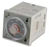


H3CR-F8 100-240AC
Analogue Timer, Recycling, Flicker Off Start, 14 Ranges, 0.05 s, 300 h, Solid State
- Manufacturer: OMRON INDUSTRIAL AUTOMATION
- Product type: Analogue Timers
- Product Range:-; Timer Functions:Flicker Off Start; No. of Timing Ranges:14Ranges; Time Min:0.05s; Time Max:300h; Timer Output:Solid State; Supply Voltage Max:240VAC; Current Rating Nom:5A; Connection /
- SVHC: No SVHC (17-Dec-2014)
- Time Max: 300h
- Time Min: 0.05s
- Timer Output: Solid State
- Product Range: -
- Timer Functions: Flicker Off Start
- Current Rating Nom: 5A
- Panel Cutout Width: 45mm
- Supply Voltage Max: 240VAC
- Panel Cutout Height: 45mm
- No. of Timing Ranges: 14Ranges
- Connection / Termination: Plug-In
| Delivery and price | |
|---|---|
| Units per pack | 60 |
| Price | 63.83 € |
| Current stock | 10+ |
| Lead time | 30 days |
## OMRON **Solid-state Timer H3CR** a

## **DIN 48 x 48-mm Multifunctional Timer Series**

- Conforms to EN61812-1 and EN60664-1 (VDE0110) 4 kV/2.

- Conforms to EMC standards (EN50081-2 and EN50082-2).

Approved by UL and CSA.

Lloyds/NK approvals. Six-language instruction manual provided.

## ~~|~~ **Broad Line-up of H3CR Series**

## **H3CR**

**==> picture [414 x 134] intentionally omitted <==**

**----- Start of picture text -----**<br>
H3CR-A H3CR-F H3CR-G H3CR-H<br>Twin Timer Star-delta Timer<br>**----- End of picture text -----**<br>


**Power OFF-delay Timer** H3CR-HRL 11-pin model H3CR-H8L 8-pin model H3CR-H8RL 5

## **Multifunctional Timer**

H3CR-A H3CR-F H3CR-G8L H3CR-AS 11-pin model H3CR-FN 11-pin model H3CR-G8EL 8-pin model H3CR-AP H3CR-F-300 H3CR-A8 8-pin model H3CR-FN-300 H3CR-A8S H3CR-F8 H3CR-A8E 8-pin with H3CR-F8N instantaneous H3CR-F8-300 8-pin model contact output H3CR-F8N-300 | model

**Note:** H3CR-AS, H3CR-A8S: Transistor output models

## **Contents**

## **Solid-state Timer**

|H3CR-A<br>.. . . . . . . . . . . . . . . . . . . . . . . . . . . . . . . . . . . . . . . . . . . . . . . . . . . . . . . . . . .|. . . . . . . . . . . . . . . . . . . . . . . . . . . . . . . . . . . . . . . . . . . . . . . . . . . . . . . . . . .|4|
|---|---|---|
|H3CR-F<br>. . . . . . . . . . . . . . . . . . . . . . . . . . . . . . . . . . . . . . . . . . . . . . . . . . . . . . . . . . . .|. . . . . . . . . . . . . . . . . . . . . . . . . . . . . . . . . . . . . . . . . . . . . . . . . . . . . . . . . . . .|23|
|H3CR-G<br>. . . . . . . . . . . . . . . . . . . . . . . . . . . . . . . . . . . . . . . . . . . . . . . . . . . . . . . . . . . .|. . . . . . . . . . . . . . . . . . . . . . . . . . . . . . . . . . . . . . . . . . . . . . . . . . . . . . . . . . . .|29|
|H3CR-H<br>. . . . . . . . . . . . . . . . . . . . . . . . . . . . . . . . . . . . . . . . . . . . . . . . . . . . . . . . . . . .|. . . . . . . . . . . . . . . . . . . . . . . . . . . . . . . . . . . . . . . . . . . . . . . . . . . . . . . . . . . .|36|
|**Common to ALL Timers**|||
|Operation<br>.. . . . . . . . . . . . . . . . . . . . . . . . . . . . . . . . . . . . . . . . . . . . . . . . . . . . . . . . .|. . . . . . . . . . . . . . . . . . . . . . . . . . . . . . . . . . . . . . . . . . . . . . . . . . . . . . . . .|45|
|Accessories|. . . . . . . . . . . . . . . . . . . . . . . . . . . . . . . . . . . . . . . . . . . . . . . . . . . . . . . .|47|
|Precautions|. . . . . . . . . . . . . . . . . . . . . . . . . . . . . . . . . . . . . . . . . . . . . . . . . . . . . . . . .|51|


## **Common to ALL Timers**

3

~~**H3CR-A**~~

~~**H3CR-A**~~

## **Solid-state Timer**

## **H3CR-A**

## **DIN 48 x 48-mm State-of-the-art Multifunctional Timer**

- A wider power supply range reduces the number of timer models kept in stock.

- A wide range of applications through six or four operating modes.

Reduced power consumption. (Except for H3CR-A8E)

- Enables easy sequence checks through instantaneous outputs for a zero set value at any time range.

- Length, when panel-mounted with a Socket, of 80 mm or less.

- Time Setting Rings enable consistent settings and limit the setting range.

Panel Covers enable various panel designs.

- PNP input models available.

- Rich variety of inputs: Start, reset, and gate functions (11-pin models and -AP models )

## ~~Ordering Information~~

## **11-pin Models**

|**11-pin Models**||||||
|---|---|---|---|---|---|
|**Output**|**Supply voltage**|**Input type**|**Time range**|**Operating mode**<br>**(see note 2)**|**Model**|
|**Contact**|100 to 240 VAC (50/60 Hz)/<br>100 to 125 VDC|No-voltage input|0.05 s to 300 h|Six multi-modes: A,<br>B**,**B2**,**C**,**D**,**E|H3CR-A|
||24 to 48 VAC (50/60 Hz)/<br>12 to 48 VDC|||||
||100 to 240 VAC (50/60 Hz)/<br>100 to 125 VDC|||Dual-modes: G, J|H3CR-A-300|
||24 to 48 VAC (50/60 Hz)/<br>12 to 48 VDC|||||
||100 to 240 VAC (50/60 Hz)/<br>100 to 125 VDC|Voltage input||Six multi-modes: A,<br>B**,**B2**,**C**,**D**,**E|H3CR-AP|
||24 to 48 VAC (50/60 Hz)/<br>12 to 48 VDC|||||
||100 to 240 VAC (50/60 Hz)/<br>100 to 125 VDC|No-voltage input|0.1 s to 600 h||H3CR-A-301|
||24 to 48 VAC (50/60 Hz)/<br>12 to 48 VDC|||||
|**Transistor**<br>**(Photocoupler)**|24 to 48 VAC (50/60 Hz)/<br>12 to 48 VDC||0.05 s to 300 h||H3CR-AS|


4

~~**H3CR-A**~~

~~**H3CR-A**~~

## **8-pin Models**

|**8-pin Models**||||||
|---|---|---|---|---|---|
|**Output**|**Supply voltage**|**Input type**|**Time range**|**Operating mode**<br>**(see note 2)**|**Model**|
|**Contact**|100 to 240 VAC (50/60 Hz)/<br>100 to 125 VDC|No-input<br>available|0.05 s to 300 h|Four multi-modes: A,<br>B2**,**E**,**J<br>**(P**<br>**l**<br>**t**<br>**t)**<br>ower supp y s ar|H3CR-A8|
||24 to 48 VAC (50/60 Hz)/<br>12 to 48 VDC|||||
||100 to 240 VAC (50/60 Hz)/<br>100 to 125 VDC||0.1 s to 600 h||H3CR-A8-301|
||24 to 48 VAC (50/60 Hz)/<br>12 to 48 VDC|||||
|**Transistor**<br>**(Photocoupler)**|24 to 48 VAC (50/60 Hz)/<br>12 to 48 VDC||0.05 s to 300 h||H3CR-A8S|
|**Time-limit contact**<br>**and instantaneous**<br>**t**<br>**t**<br>**con ac**|100 to 240 VAC (50/60 Hz)/<br>100 to 125 VDC||||H3CR-A8E|
||24 to 48 VDC/VAC(50/60 Hz)|||||


- **Note:** 1. Specify both the model number and supply voltage when ordering. Example: H3CR-A 100 to 240 VAC (50/60 Hz)/100 to 125 VDC

Supply voltage

2. The operating modes are as follows

   - A: ON-delay

B: Flicker OFF start

- B2: Flicker ON start

C: Signal ON/OFF-delay

D: Signal OFF-delay

- E: Interval

- G: Signal ON/OFF-delay

- J: One-shot

## **Model Number Legend:**

## **H3CR-A** ��� **-** �

1 2 3 4

## **1. Number of Pins**

None: 11-pin models

   - 8: 8-pin models

**2. Input Type for 11-pin Models** None: No-voltage input (NPN type)

   - P: Voltage input (PNP type)

## **3. Output**

None: Relay output (DPDT)

- S: Transistor output (NPN/PNP universal use)

- E: Relay output (SPDT) with instantaneous relay output (SPDT)

## **4. Suffix**

300: Dual mode models (signal ON/OFF-delay and one-shot)

- 301: Double time scale (range) models (0.1 s to 600 h)

5

~~**H3CR-A**~~

~~**H3CR-A**~~

## **Accessories (Order Separately)**

|**Accessories (Order Separately)**|**Accessories (Order Separately)**||
|---|---|---|
|**Name/specifications**||**Models**|
|**Flush Mounting Adapter**||Y92F-30|
|||Y92F-70|
|||Y92F-71|
|**Mounting Track**|**50 cm (**�**) x 7.3 mm (t)**|PFP-50N|
||**1 m (**�**) x 7.3 mm (t)**|PFP-100N|
||**1 m (**�**) x 16 mm (t)**|PFP-100N2|
|**End Plate**||PFP-M|
|**Spacer**||PFP-S|
|**Protective Cover**||Y92A-48B|
|**Track Mounting/**<br>**F**<br>**t C**<br>**ti**<br>**S**<br>**k t**<br>**ron**<br>**onnec ng oc e**|**8-pin**|P2CF-08|
||**8-pin, finger safe type**|P2CF-08-E|
||**11-pin**|P2CF-11|
||**11-pin, finger safe type**|P2CF-11-E|
|**Back Connecting Socket**|**8-pin**|P3G-08|
||**8-pin, finger safe type**|P3G-08 with Y92A-48G(see note 1)|
||**11-pin**|P3GA-11|
||**11-pin, finger safe type**|P3GA-11 with Y92A-48G(see note 1)|
|**Time Setting Ring**|**Setting a specific time**|Y92S-27|
||**Limiting the setting range**|Y92S-28|
|**Panel Cover (see note 2)**|**Lightgray (5Y7/1)**|Y92P-48GL|
||**Black (N1.5)**|Y92P-48GB|
||**Mediumgray (5Y5/1)**|Y92P-48GM|
|**Hold-down Clip (see note 3)**|**For PL08 and PL11 Sockets**|Y92H-7|
||**For PF085A Socket**|Y92H-8|


- **Note:** 1. Y92A-48G is a finger safe terminal cover which is attached to the P3G-08 or P3GA-11 Socket.

   2. The Time Setting Ring and Panel Cover are sold together.

   3. Hold-down Clips are sold in sets of two.

## ~~Specifications~~

## **General**

|**General**|||||
|---|---|---|---|---|
|**Item**|**H3CR-A/-AS**|**H3CR-AP**|**H3CR-A8/-A8S**|**H3CR-A8E**|
|**Operating mode**|A:<br>ON-delay<br>B:<br>Flicker OFF start<br>B2: Flicker ON start<br>C:<br>Signal ON/OFF-delay<br>D:<br>Signal OFF-delay<br>E:<br>Interval<br>G: Signal ON/OFF-delay (Only for H3CR-A-300)<br>J:<br>One-shot (Only for H3CR-A-300)||A:<br>ON-delay (power supply start)<br>B2: Flicker ON start (power supply start)<br>E:<br>Interval (power supply start)<br>J:<br>One-shot (power supply start)||
|**Pin type**|11-pin||8-pin||
|**Input type**|No-voltage input|Voltage input|---||
|**Time-limit output**<br>**type**|H3CR-A/-A8/-AP: Relay output (DPDT)<br>H3CR-AS/-A8S:<br>Transistor output (NPN/PNP universal)*|||Relay output (SPDT)|
|**Instantaneous output**<br>**type**|---|||Relay output (SPDT)|
|**Mounting method**|DIN track mounting, surface mounting, and flush mounting||||
|**Approved standards**|UL508, CSA C22.2 No.14, NK, Lloyds<br>Conforms to EN61812-1 (VDE0435/P2021), IEC60664-1 (VDE0110) 4kV/2, EN60947-5-1 (for contact output),<br>and EN60947-5-2(for non-contact output).||||


*The internal circuits are optically isolated from the output. This enables universal application as NPN or PNP transistor.

6

~~**H3CR-A**~~

~~**H3CR-A**~~

## **Time Ranges**

**Note:** When the time setting knob is turned below “0” until the point where the time setting knob stops, the output will operate instantaneously at all time range settings.

## **Standard (0.05-s to 300-h) Models**

|**Time unit**||**s (sec)**|**s (sec)**|**min**|**h (hrs)**|**x10 h (10 h)**|
|---|---|---|---|---|---|---|
|**Full scale**<br>**tti**<br>**se**<br>**ng**|1.2|0.05 to 1.2||0.12 to 1.2||1.2 to 12|
||3|0.3 to 3||||3 to 30|
||12|1.2 to 12||||12 to 120|
||30|3 to 30||||30 to 300|
|**Double (0.1-s to 600-h) Models**|||||||
|**Time unit**||**s (sec)**||**min**|**h (hrs)**|**x10 h (10 h)**|
|**Full scale**<br>**tti**<br>**se**<br>**ng**|2.4|0.1 to 2.4||0.24 to 2.4||2.4 to 24|
||6|0.6 to 6||||6 to 60|
||24|2.4 to 24||||24 to 240|
||60|6 to 60||||60 to 600|
|**Ratings**|||||||
|**Rated supply voltage (see note 1)**|||100 to 240 VAC (50/60 Hz)/100 to 125 VDC, 24 to 48 VAC (50/60 Hz)/12 to 48 VDC (24 to<br>48 VAC/VDC for H3CR-A8E) (see note 2)||||
|**Operating voltage range**|||85% to 110% of rated supplyvoltage(90% to 110% at 12 VDC)||||
|**Power reset**|||Minimumpower-openingtime: 0.1 s||||
|**Input**|||No-voltage Input<br>ON impedance:<br>1 kΩmax.<br>ON residual voltage: 1 V max.<br>OFF impedance:<br>100 kΩmin.<br>Voltage Input<br>Max. permissible capacitance between inputs lines (terminals 6 and 7): 1,200 pF<br>Load connectable in parallel with inputs (terminals 6 and 7).<br>• 100to 240 VAC/100 to 125 VDC<br>High (logic) level: 85 to 264 VAC/85 to 137.5 VDC<br>Low (logic) level: 0 to 10 VAC/0 to 10 VDC<br>• 24 to 48 VAC/12 to 48 VDC<br>High (logic) level: 20.4 to 52.8 VAC/10.8 to 52.8 VDC<br>Low (logic) level: 0 to 2.4 VAC/0 to 1.2 VDC||||
|**Power consumption**|||H3CR-A/-A8<br>• 100to 240 VAC/100 to 125 VDC<br>(When at 240 VAC, 60 Hz)<br>Relay ON: approx. 2.1 VA (1.6 W)<br>Relay OFF: approx. 1.3 VA (1.1 W)<br>• 24 to 48 VAC/12 to 48 VDC<br>(When at 24 VDC)<br>Relay ON: approx. 0.8 W<br>Relay OFF: approx. 0.2 W<br>H3CR-AP<br> (see note 3)<br>• 100to 240 VAC/100 to 125 VDC<br>(When at 240 VAC, 60 Hz)<br>Relay ON: approx. 2.5 VA (2.2 W)<br>Relay OFF: approx. 1.8 VA (1.7 W)<br>• 24 to 48 VAC/12 to 48 VDC<br>(When at 24 VDC)<br>Relay ON: approx. 0.9 W<br>Relay OFF: approx. 0.3 W<br>H3CR-A8E<br>• 100to 240 VAC/100 to 125 VDC<br>(When at 240 VAC, 60 Hz)<br>Relay ON/OFF: approx. 2 VA (0.9  W)<br>• 24 to 48 VAC/VDC<br>(When at 24 VDC)<br>Relay ON/OFF: approx. 0.9 W<br>H3CR-AS/-A8S<br>• 24 to 48 VAC/12 to 48 VDC<br>(When at 24 VDC)<br>Output ON: 0.3 W  Output OFF: 0.2 W||||
|**Control outputs**|||Time limit contacts:<br>5 A at 250 VAC/30 VDC, resistive load (cosφ= 1)<br>Transistor output:<br>Open collector (NPN/PNP), 100 mA max. at 30 VDC max.,<br>residual voltage: 2 V max.<br>Instantaneous contact: 5 A at 250 VAC,resistive load(cosφ= 1)||||


- **Note:** 1. DC ripple rate: 20% max. if the power supply incorporates a single-phase, full-wave rectifier.

   2. Each 24-to-48-VAC/12-to-48-VDC model causes an inrush current of approximately 0.85 A. Pay careful attention when attempting to turn ON power to such a model with non-contact output from a device such as a sensor.

   3. The values are for when the terminals 2 and 7 and terminals 10 and 6 are short-circuited, and include the consumption current of the input circuit.

7

~~**H3CR-A**~~

~~**H3CR-A**~~

## **Characteristics**

|**Accuracy of**<br>**operating time**|±0.2% FS max. (±0.2%±10 ms max. in a range of 1.2 s)|
|---|---|
|**Setting error**|±5% FS±50 ms(see note)|
|**Reset time**|Min. power-opening time: 0.1 s max.<br>Min. pulse width:<br>0.05 s (H3CR-A/-AS)|
|**Reset voltage**|10% max. of rated voltage|
|**Influence of voltage**|±0.2% FS max.(±0.2%±10 ms max. in a range of 1.2 s)|
|**Influence of**<br>**temperature**|±1% FS max. (±1%±10 ms max. in a range of 1.2 s)|
|**Insulation**<br>**resistance**|100 MΩmin. (at 500 VDC)|
|**Dielectric strength**|2,000 VAC (1,000 VAC for H3CR-A�S), 50/60 Hz for 1 min (between current-carrying metal parts and<br>exposed non-current-carrying metal parts)<br>2,000 VAC (1,000 VAC for H3CR-A�S), 50/60 Hz for 1 min (between control output terminals and operating<br>circuit)<br>2,000 VAC, 50/60 Hz for 1 min (between contacts of different polarities)<br>1,000 VAC, 50/60 Hz for 1 min (between contacts not located next to each other)<br>2,000 VAC, 50/60 Hz for 1 min (between input and control output terminals and operation circuit)|
|**Impulse withstand**<br>**voltage**|3 kV (between power terminals) for 100 to 240 VAC/100 to 125 VDC, 1 kV for 24 to 48 VAC/12 to 48 VDC<br>4.5 kV (between current-carrying terminal and exposed non-current-carrying metal parts) for 100 to<br>240 VAC/100 to 125 VDC, 1.5 kV for 24 to 48 VAC/12 to 48 VDC and 24 to 48 VAC/VDC|
|**Noise immunity**|±1.5 kV (between power terminals) and±600 V (between no-voltage input terminals), square-wave noise by<br>noise simulator (pulse width: 100 ns/1µs, 1-ns rise)|
|**Static immunity**|Malfunction:<br>8 kV<br>Destruction:<br>15 kV|
|**Vibration resistance**|Destruction:<br>10 to 55 Hz with 0.75-mm double amplitude each in 3 directions for 2 hours each<br>Malfunction:<br>10 to 55 Hz with 0.5-mm double amplitude each in 3 directions for 10 minutes each|
|**Shock resistance**|Destruction:<br>1,000 m/s23 times each in 6 directions<br>Malfunction:<br>100 m/s23 times each in 6 directions|
|**Ambient**<br>**temperature**|Operating:<br>–10°C to 55°C (with no icing)<br>Storage:<br>–25°C to 65°C (with no icing)|
|**Ambient humidity**|Operating:<br>35% to 85%|
|**Life expectancy**|Mechanical:<br>20,000,000 operations min. (under no load at 1,800 operations/h)<br>Electrical:<br>100,000 operations min. (5 A at 250 VAC, resistive load at 1,800 operations/h)|
|**EMC**|(EMI)<br>EN50081-2<br>Emission Enclosure:<br>EN55011 Group 1 class A<br>Emission AC Mains:<br>EN55011 Group 1 class A<br>(EMS)<br>EN50082-2<br>Immunity ESD:<br>EN61000-4-2:<br>4 kV contact discharge (level 2)<br>8 kV air discharge (level 3)<br>Immunity RF-interference from AM Radio Waves:<br>ENV50140:10 V/m (80 MHz to 1 GHz)<br>(level 3)<br>Immunity RF-interference from Pulse-modulated Radio Waves:<br>ENV50204:10 V/m (900±5 MHz) (level 3)<br>Immunity Conducted Disturbance:ENV50141:<br>10 V (0.15 to 80 MHz) (level 3)<br>Immunity Burst:<br>EN61000-4-4:<br>2 kV power-line (level 3)<br>2 kV I/O signal-line (level 4)<br>Immunity Surge:<br>EN61000-4-5:<br>1 kV line to line<br>2 kV line to ground (level 3)|
|**Case color**|Lightgray (Munsell 5Y7/1)|
|**Degree ofprotection**|IP40(panel surface)|
|**Weight**|Approx. 90g|


**Note:** The value is ±5% FS +100 ms to –0 ms max. when the C, D, or G mode signal of the H3CR-AP is OFF.

8

~~**H3CR-A**~~

~~**H3CR-A**~~

## ~~Engineering Data~~

**==> picture [470 x 150] intentionally omitted <==**

**----- Start of picture text -----**<br>
10,000<br>5,000<br>=====—<br>ira<br>1,000<br>Rf 30 VDC L/R = 7 ms Reference: A maximum current of 0.15 A can be switched at 125 VDC (cosφ = 1)<br>500 | and a maximum current of 0.1 A can be switched if L/R is 7 ms. In<br>AFOOT 250 VAC/30 VDC both cases, a life of 100,000 operations can be expected.<br>(cosφ = 1) The minimum applicable load is 10 mA (100 mA for H3CR-A8E) at<br>PARSE 5 VDC (failure level: P).<br>100<br>p> See<br>250 VAC (cosφ = 0.4)<br>0 1 2 3 jj<br>Load current (A)<br>3<br>Switching operations (x 10   )<br>**----- End of picture text -----**<br>


## ~~Nomenclature~~

Power indicator (green) (Flashes when Timer operates; lit when Timer stops operating)

Operating mode display window

Output indicator (orange) (Lit when output)

Operating mode selector Select a mode from: A, B, B2, C, D, and E (H3CR-A, -AP, and -AS) A, B2, E and J (H3CR-A8, -A8S, and -A8E) G and J (H3CR-A-300)

Scale range display windows

Time range selector (select o ~~ne~~ from 1.2, 3, 12, and 30 at full scale; with the H3CR-A 4 -301, select from 2.4, 6, 24, or 60 at full scale. )

Time setting knob (set time)

Time unit display window Time unit selector (select one from sec, min, hrs, and 10h)

9

~~**H3CR-A**~~

~~**H3CR-A**~~

## ~~Operation~~

## **Block Diagrams**

## **H3CR-A/AS**

## **H3CR-AP**

**==> picture [336 x 206] intentionally omitted <==**

**----- Start of picture text -----**<br>
Zero setting<br>AC (DC) input detection Time range/ Operating<br>unit selectors mode selector<br>circuit<br>Power supply Oscillation Counting<br>circuit circuit circuit Output circuit<br>Indicator<br>Reset input, start input, and gate input Input circuit circuit<br>Power-ON Output-ON<br>indicator indicator<br>**----- End of picture text -----**<br>


**==> picture [336 x 205] intentionally omitted <==**

**----- Start of picture text -----**<br>
Zero setting<br>AC (DC) input detection Time range/ Operating<br>unit selectors mode selector<br>circuit<br>Power supply Oscillation Counting<br>circuit circuit circuit Output circuit<br>Indicator<br>Start Input circuit circuit<br>Power-ON Output-ON<br>indicator indicator<br>**----- End of picture text -----**<br>


10

~~**H3CR-A**~~

~~**H3CR-A**~~

## **H3CR-A8/A8S**

## **H3CR-A8E**

**==> picture [336 x 472] intentionally omitted <==**

**----- Start of picture text -----**<br>
Zero setting<br>AC (DC) input detection Time range/ Operating<br>unit selectors mode selector<br>circuit<br>Power supply Oscillation Counting<br>circuit circuit circuit Output circuit<br>Indicator<br>circuit<br>Power-ON Output-ON<br>indicator indicator<br>Zero setting<br>AC (DC) input detection Time range/ Operating<br>unit selectors mode selector<br>circuit<br>Power supply Oscillation Counting<br>circuit circuit circuit Output circuit<br>Indicator<br>circuit<br>Power-ON Output-ON<br>indicator indicator<br>Instantaneous<br>output circuit<br>**----- End of picture text -----**<br>


## **I/O Functions**

|**Inputs**<br>**(for -A/-AS**<br>**models)**|**Start**|Startstime-measurement.|
|---|---|---|
||**Reset**|Interrupts time-measurement and resets time-measurement value. No time-measurement is made<br>and control output is OFF while the reset input is ON.|
||**Gate**|Prohibits time-measurement.|
|**Outputs**|**Control output**|Outputs are turned ON accordingto designated output mode whenpreset value is reached.|


**Note:** H3CR-AP incorporates start input only.

11

~~**H3CR-A**~~

~~**H3CR-A**~~

## **Timing Chart**

**Note:** 1. The minimum power-opening time (“Rt”) is 0.1 s and the minimum pulse width is 0.05 s.

2. The letter “t” in the timing charts stands for the set time and “t–a” means that the period is less than the time set.

## **H3CR-A/-AS/-AP***

- *H3CR-AP model incorporates start input only.

|**Operating**<br>**mode**|**Timing chart**|
|---|---|
|A:<br>ON-delay|Power<br>Output<br>t<br>Basic operation<br>Power<br>Start<br>Reset<br>Output relay (NC)<br>Output relay (NO)<br>(Output indicator)<br>Power indicator<br>t<br>t<br>**Note:**<br>Startinput is invalidwhile the Tim-<br>eris in operation.<br>Start<br>(see note)<br>~~[id~~<br>Pt cn TC<br>i|
|B:<br>Flicker OFF<br>start|Power<br>Output relay (NO)<br>(Output indicator)<br>Power indicator<br>Start<br>Reset<br>Output relay (NC)<br>Basicoperation<br>Power<br>Output<br>t<br>t<br>t<br>t<br>**Note:**<br>Start input is invalid while<br>theTimer is in operation.<br>Start<br>(see note)<br>[<br>ee<br>:<br>ee<br>—__e_e|
|B2:<br>Flicker ON<br>start|Basic operation<br>Power<br>Output<br>t<br>t<br>t<br>t<br>Power<br>Start<br>Reset<br>Output relay (NO)<br>(Output indicator)<br>Power indicator<br>Output relay (NC)<br>**Note:**<br>Startinput is invalidwhile the Tim-<br>eris in operation.<br>Start<br>(see note)<br>a<br>:|
|C:<br>Signal<br>ON/OFF-<br>delay|Basicoperation<br>Power<br>Output<br>t<br>t<br>t<br>t<br>Power<br>Start<br>Reset<br>Output relay (NC)<br>Power indicator<br>Output relay (NO)<br>(Output indicator)<br>**Note:**<br>Start input is valid and re-<br>triggerablewhile the Timeris<br>inoperation.<br>Start<br>(see note)|


12

~~**H3CR-A**~~

~~**H3CR-A**~~

|**Operating**<br>**mode**|**Timing chart**|
|---|---|
|D:<br>Signal<br>OFF-delay|Basic operation<br>Power<br>Output<br>t<br>Output relay (NC)<br>Power indicator<br>Power<br>Start<br>Reset<br>Output relay (NO)<br>(Output indicator)<br>**Note:**<br>Start input is valid and<br>re-triggerablewhile the<br>Timeris in operation.<br>Start<br>(see note)|
|E:<br>Interval|Power<br>Output<br>t<br>Basic operation<br>Power<br>Start<br>Reset<br>Output relay (NC)<br>Power indicator<br>Output relay (NO)<br>(Output indicator)<br>**Note:**<br>Start input is valid and<br>re-triggerable<br>while<br>the Timer is in opera-<br>tion.<br>Start<br>(see note)<br>=<br>an<br>ee<br>eee<br>es<br>fe|
|G:<br>Signal<br>ON/OFF-<br>delay|Basicoperation<br>Power<br>Start<br>Reset<br>Output relay (NC)<br>Power indicator<br>Power<br>Output<br>t<br>t<br>Output relay (NO)<br>(Output indicator)<br>**Note:**<br>Start input is valid and re-trigger-<br>ablewhilethe Timer is in operation.<br>t<br>t<br>Start<br>(see note)<br>t<br>t<br>ta,<br>t<br>ta<br>t<br>Snesa|
|J:<br>One-shot<br>output|Basicoperation<br>Power<br>Start<br>Reset<br>Output relay (NC)<br>Power indicator<br>1±0.6 s<br>(Fixed)<br>1±0.6 s<br>(Fixed)<br>Output<br>Power<br>Output relay (NO)<br>(Output indicator)<br>1±0.6 s<br>(Fixed)<br>**Note:**<br>Start input is valid and re-<br>triggerable while the Timer<br>isin operation.<br>Start<br>(see note)<br>t<br>1<br>‘8<br>t<br>...._]<br>| a]<br>| |<br>a|


## **Gate Signal Input**

t1 t2

ON Power OFF ON Start OFF ON Gate OFF ON Reset OFF Output ON relay OFF

**Note:** 1. This timing chart indicates the gate input in operating mode A (ON-delay operation).

2. The set time is the sum of t1 and t2.

3. H3CR-AP model incorporates start input only.

13

~~**H3CR-A**~~

~~**H3CR-A**~~

## **H3CR-A8/-A8S**

**==> picture [461 x 365] intentionally omitted <==**

**----- Start of picture text -----**<br>
Operating Timing chart<br>mode<br>A:  t Rt t Rt t~a<br>ON-delay Power a | [be] Basic operation<br>Output relay<br>(NC) Power<br>Output relay t<br>(NO) (output<br>indicator) Output<br>Power REA AB web a TT et<br>indicator<br>B2: se ta Rt i a ta<br>Flicker ON<br>start Power eT eee | Basic operation<br>Output relay a eeeeeee| |_|<br>(NC) Power<br>Output relay t t t t<br>(NO) (output<br>indicator) Output<br>Power<br>indicator<br>E:<br>Interval :<br>Power<br>[ee Rt eeet Rt t-a<br>Basic operation<br>Output relay<br>(NC)<br>Power<br>Output relay<br>(NO) (output | —_ t +—-——-.<br>indicator) Output<br>Power PAGE Fs TARE AMI Be<br>indicator<br>J: Rt ta At<br>One-shot a<br>output Power<br>Output relay a _......_ Basic operation<br>(NC)<br>1±0.6 s 1±0.6 s Power<br>Output relay (Fixed) (Fixed)<br>(NO) (output t 1±0.6 s<br>indicator)Power anaowimm Output (Fixed)<br>indicator<br>[ono _onaoul<br>**----- End of picture text -----**<br>


14

~~**H3CR-A**~~

~~**H3CR-A**~~

## **H3CR-A8E**

**==> picture [466 x 479] intentionally omitted <==**

**----- Start of picture text -----**<br>
Operating Timing chart<br>mode<br>A:  t Rt t Rt t—a<br>ON-delay Power<br>[i eee ie<br>Output relay<br>(NC)<br>Output relay Basic operation<br>(NO) (output<br>indicator) —<br>Instantaneous Power<br>output relay (NC)<br>t<br>Instantaneous<br>output relay (NO) Output<br>Power indicator<br>ET gE es UT ES TS ees eae<br>uanaguict hasan an |<br>B2: t t ta Rt t ' t t-a<br>Flicker ON<br>start Power | |__|<br>Output relay<br>(NC) oa Basic operation<br>Output relay<br>(NO) (output<br>indicator) Power<br>Instantaneous t t t t<br>output relay (NC)<br>Instantaneous ae eee Output<br>output relay (NO)<br>Power indicator<br>E:  t Rt Rt t-—a<br>Interval Power<br>Le t |<br>Output relay<br>(NC) eo<br>Output relay<br>(NO) (outputindicator) Basic operation<br>Instantaneous<br>output relay (NC) ne a [ Power<br>Instantaneous<br>ee a t E<br>output relay (NO)<br>Output<br>Power indicator EW eT BARES Ey Ed Gf HRB ene<br>J: Annafe t henna Rt tea Rt t on —<br>One-shot<br>output Power ee eS Ee<br>Output relay<br>(NC)<br>Output relay<br>(NO) (outputindicator) a, (Fixed) | || (Fixed) ER Basic operation<br>Instantaneous<br>output relay (NC) Power<br>Instantaneous t 1±0.6 s<br>output relay (NO) (Fixed)<br>Output<br>Power indicator<br>**----- End of picture text -----**<br>


15

~~OTRO~~ ~~**H3CR-A H3CR-A**~~

## ~~Dimensions~~

**Note:** All units are in millimeters unless otherwise indicated.

**==> picture [416 x 342] intentionally omitted <==**

**----- Start of picture text -----**<br>
H3CR-A<br>H3CR-AP 15 66.6<br>H3CR-AS 6 52.3<br>48 0.7<br>48 39 dia. 44.8 x 44.8<br>4A = =<br>i Wee<br>Oyse 8 6 ) e k 11 pins<br>H3CR-A8<br>H3CR-A8S<br>H3CR-A8E 15<br>66.6<br>6 52.3<br>48 0.7<br>a a<br>48 39 dia. 44.8 x 44.8<br>8 pins<br>Dimensions with Set Ring 16.5<br>50<br>50 42 dia.<br>Time Setting Panel cover<br>Ring<br>**----- End of picture text -----**<br>


**==> picture [461 x 146] intentionally omitted <==**

**----- Start of picture text -----**<br>
Dimensions with Front Connecting Socket Dimensions with Back Connecting Socket<br>P2CF-08- o /P2CF-11- o P3G-08/P3GA-11<br>15 81.5 15 81.5<br>80 75<br>H3CR-A H3CR-A8<br>100.8* H3CR-AS 98.5 89.9* 87.6 H3CR-AH3CR-AS + H3CR-A8<br>+ Adapter<br>Adapter<br>P3G-08<br>6D d Y92F-30 o [P3GA-11] e Y92F-30<br>(When (When<br>P2CF-11 2.3* P2CF-08 2.3* Y92A-48G Y92A-48G<br>P2CF-11-E P2CF-08-E mounted) mounted)<br>**----- End of picture text -----**<br>


- *These dimensions vary with the kind of DIN track (reference value).

16

~~**H3CR-A**~~

~~**H3CR-A**~~

## ~~Installation~~

## **Terminal Arrangement**

**Note:** The delayed contact of conventional Timers was indicated as

The contact symbol of the H3CR-A is indicated as          because its operating mode is six multi-modes (four multi-modes for the H3CR-A8).

## **11-pin Models**

## **H3CR-A (Contact Output)**

**==> picture [215 x 299] intentionally omitted <==**

**----- Start of picture text -----**<br>
(–)(~) Power supply (+)(~)<br>H3CR-AS (Transistor Output)<br>(–)(~) Power supply (+)(~)<br>Reset input Start input Gate input<br>Reset input Start input Gate input<br>**----- End of picture text -----**<br>


## **H3CR-AS (Transistor Output)**

**Note:** Terminals 1, 3, 4, and 8 are empty. Terminals 2, 5, 6, 7, and 10 are the same as for the H3CR-A.

## **H3CR-AP (Contact Output)**

**==> picture [193 x 134] intentionally omitted <==**

**----- Start of picture text -----**<br>
(–)(~) Power supply (+)(~)<br>Start input<br>**----- End of picture text -----**<br>


## **8-pin Models**

## **H3CR-A8 (Contact Output)**

**==> picture [154 x 106] intentionally omitted <==**

**----- Start of picture text -----**<br>
(–) (+)<br>(~) (~)<br>Power supply<br>**----- End of picture text -----**<br>


## **H3CR-A8S (Transistor Output)**

**==> picture [154 x 106] intentionally omitted <==**

**----- Start of picture text -----**<br>
(–) (+)<br>(~) (~)<br>Power supply<br>**----- End of picture text -----**<br>


**Note:** Terminals 1, 3, 4, and 5 are empty. Terminals 2 and 7 are the same as for the H3CR-A8.

## **H3CR-A8E (Contact Output)**

**==> picture [154 x 106] intentionally omitted <==**

**----- Start of picture text -----**<br>
(–) (+)<br>(~) (~)<br>Power supply<br>**----- End of picture text -----**<br>


**Note:** Terminal 5 is empty.

17

~~**H3CR-A**~~

~~**H3CR-A**~~

## **Input Connections H3CR-A/-AS**

The inputs of the H3CR-A/-AS are no-voltage (short-circuit or open) inputs.

## **No-voltage Inputs**

**Contact Input**

**No-contact Input** (Connection to NPN open collector output sensor.)

**==> picture [250 x 127] intentionally omitted <==**

**----- Start of picture text -----**<br>
12 to 24 VDC<br>(sensor power supply)<br>+ DC power<br>– supply<br>Timer Timer<br>Sensor<br>5 Gate 5 Gate<br>6 Start 6 Start<br>7 Reset<br>7 Reset<br>2 Input (0 V) 2 Input (0 V)<br>Operates with transistor ON Operates with relay ON<br>**----- End of picture text -----**<br>


## **No-contact Input**

(Connection to a voltage output sensor.)

**==> picture [118 x 128] intentionally omitted <==**

**----- Start of picture text -----**<br>
12 to 24 VDC<br>(sensor power supply)<br>+ DC power<br>– supply<br>Timer<br>Sensor<br>5 Gate<br>6 Start<br>7 Reset<br>2 Input (0 V)<br>Operates with transistor ON<br>**----- End of picture text -----**<br>


## **No-voltage Input Signal Levels**

No-contact 1. Short-circuit level input Transistor ON Residual voltage: 1 V max. Impedance when ON: 1 kΩ max. 2. Open level Transistor OFF Impedance when OFF: 100 kΩ min. Contact Use contacts which can adequateinput ly switch 0.1 mA at 5 V

18

~~**H3CR-A**~~

~~**H3CR-A**~~

## **H3CR-AP**

The start input of the H3CR-AP is voltage input. (Voltage imposition or open)

**==> picture [481 x 450] intentionally omitted <==**

**----- Start of picture text -----**<br>
Voltage Inputs<br>No-contact Input No-contact Input Contact Input<br>(Connection to PNP open (Connection to NPN open<br>collector output sensor) collector output sensor)<br>12 to 24 VDC  12 to 24 VDC<br>(sensor power supply) (sensor power supply)<br>+ DC power + DC power<br>– supply – supply<br>Sensor Sensor<br>Timer Timer<br>Timer<br>10 Power 10 Power<br>supply (+) supply (+) 10 Power<br>supply (+)<br>6 Start 6 Start<br>6 Start<br>7 Input 0V 7 Input 0V 7 Input 0V<br>2 Power  2 Power<br>supply  supply  2 Power<br>(–) (–) supply<br>(–)<br>Operates with PNP transistor ON Operates with NPN transistor ON Operates with relay ON<br>Note: The input circuit is isolated from the Note: Refer to the signal levels in the fol-<br>4D d© power supply circuit. Thus, an NPN HO lowing table and be aware of the<br>transistor can be connected. minimum applicable load of the relay.<br>Voltage Input Signal Levels<br>No-contact 1. Transistor ON<br>input Residual voltage: 1 V max.<br>The voltage between terminals 6 and 7 must be 10.8 VDC min.<br>2. Transistor OFF<br>Leakage current: 0.01 mA max.<br>The voltage between terminals 6 and 7 must be 1.2 VDC max.<br>Contact Use contacts that can adequately switch 0.1 mA at each oper-<br>input ating voltage.<br>The voltage between terminals 6 and 7 with contacts ON or<br>OFF must satisfy the specified value.<br>Contacts ON<br>100-to-240-VAC and 100-to-125-VDC models: 85 to 264 VAC<br>or 85 to 137.5 VDC<br>24-to-48-VAC and 12-to-48-VDC models: 20.4 to 52.8 VAC or<br>10.8 to 52.8 VDC<br>Contacts OFF<br>100-to-240-VAC and 100-to-125-VDC models: 0 to 10 VAC or<br>0 to 10 VDC<br>24-to-48-VAC and 12-to-48-VDC models: 0 to 2.4 VAC or 0 to<br>1.2 VDC<br>AC power supply DC power supply<br>**----- End of picture text -----**<br>


19

~~**H3CR-A**~~

~~**H3CR-A**~~

## **Application Examples**

## **A Mode: ON-delay**

ON-delay operation (A mode) is a basic mode.

## **1. Power-ON Start/Power-OFF Reset**

The Power-ON start/Power-OFF reset operation is a standard operating method.

**==> picture [181 x 186] intentionally omitted <==**

**----- Start of picture text -----**<br>
t<br>Power (2 and 10)<br>Start (2 and 6)<br>Control output: NC (8 and 11)<br>NC (1 and 4)<br>Control output: NO (9 and 11)<br>NO (1 and 3)<br>Power indicator<br>Flashing Lit<br>Externally short-circuited<br>° | 4 ° 8 d<br>C4<br>Power<br>supply<br>**----- End of picture text -----**<br>


## **2. Signal Start/Signal Reset**

The Signal start/Signal reset operation is useful for remote control of the Timer.

Power (2 and 10) Start (2 and 6) an Reset (2 and 7) | ES Control output: NC (8 and 11) NC (1 and 4) EEE————— eee Control output: NO (9 and 11) NO (1 and 3) | rrr Power indicator TEEN Lit MARANA Flashing ~~Ee~~ Lit

**==> picture [124 x 110] intentionally omitted <==**

**----- Start of picture text -----**<br>
Start signal (remote control possible)<br>Reset signal<br>(remote control possible)<br>] y D<br>© O ne.<br>"s<br>Power<br>supply<br>(Power continuously supplied)<br>e re<br>**----- End of picture text -----**<br>


## **3. Control of Integrated Time with Gate Signal**

With a gate signal, the Power-ON start operation and Signal start operation can be controlled (the operation can be interrupted).

**==> picture [204 x 117] intentionally omitted <==**

**----- Start of picture text -----**<br>
t1 t2 t1 + t2: set time<br>Power (2 and 10)<br>Start (2 and 6)<br>Gate (2 and 5)<br>Control output: NC (8 and 11)<br>NC (1 and 4)<br>Control output: NO (9 and 11)<br>NO (1 and 3)<br>Power indicator<br>NOEela Flashing  Gan Lit e<br>**----- End of picture text -----**<br>


**==> picture [139 x 91] intentionally omitted <==**

**----- Start of picture text -----**<br>
Gate signal (The operation is interrupted with the<br>gate signal if the Timer detects an abnormal signal.) ane<br>Externally<br>short-circuited 4 8<br>Power<br>— supply<br>**----- End of picture text -----**<br>


## **B/B2 Mode: Flicker**

The flicker operation in the B and B2 modes can be effectively applied to lamp or buzzer (ON and OFF) alarms or the monitoring of an intermittent operation with a display.

**==> picture [200 x 114] intentionally omitted <==**

**----- Start of picture text -----**<br>
1. Power-ON Start/Power-OFF Reset (in B Mode)<br>tepetefetefeteletatetetetetet<br>Power (2 and 10)<br>es<br>Start (2 and 6)<br>a<br>Control output: NC (8 and 11)<br>NC (1 and 4)<br>conc Mie<br>Control output: NO (9 and 11)<br>NO (1 and 3) ie ome i oe<br>Power indicator<br>ual Flashing lal<br>**----- End of picture text -----**<br>


**==> picture [184 x 79] intentionally omitted <==**

**----- Start of picture text -----**<br>
Externally short-circuited<br>‘<br>2 10 9<br>mantra.<br>Power<br>| [Ps] = [y] supply [,]<br>**----- End of picture text -----**<br>


20

~~**H3CR-A**~~

~~**H3CR-A**~~

## **2. Signal Start/Signal Reset (in B Mode)**

If there is an abnormal signal, flashing starts. When the abnormal condition is restored, a reset signal stops the display flashing.

**==> picture [210 x 210] intentionally omitted <==**

**----- Start of picture text -----**<br>
Power (2 and 10)<br>Start (2 and 6)<br>Reset (2 and 7)<br>PT tii tits<br>Control output: NC (8 and 11)<br>NC (1 and 4) ee ee<br>Control output: NO (9 and 11) -s-i-0-5<br>NO (1 and 3)<br>Power indicator<br>Lit Flashing Lit<br>O™O Start signal<br>Reset signal<br>- ,°<br>Lp Power pom<br>supply<br>| |<br>(Power continuously supplied)<br>**----- End of picture text -----**<br>


## **2. Signal-ON-OFF Start/Instantaneous Operation/Time-limit Reset**

**==> picture [212 x 205] intentionally omitted <==**

**----- Start of picture text -----**<br>
Power (2 and 10)<br>Start (2 and 6)<br>Control output: NC (8 and 11)<br>NC (1 and 4)<br>Control output: NO (9 and 11) .=—=—:=<br>Power indicatorNO (1 and 3) PySeeOneal nAlanes<br>Start signal<br>(The operation starts with the signal ON or OFF)<br>OU<br>° 1 4 , 8 j<br>Power<br>a supply<br>Lit Flashing Lit Flashing Lit Flashing Lit<br>**----- End of picture text -----**<br>


**==> picture [81 x 7] intentionally omitted <==**

**----- Start of picture text -----**<br>
(Power continuously supplied)<br>**----- End of picture text -----**<br>


## **D Mode: Signal OFF-delay**

## **C Mode: Signal ON/OFF-delay**

The Signal ON-/OFF-delay operation (C mode) is useful for the control of distribution of products on a production line into boxes by the specified number or time.

## **1. Power-ON Start/Instantaneous Operation/Time-limit Reset**

A set of these functions is useful for the operation of a machine for a specified period when power is ON.

**==> picture [80 x 61] intentionally omitted <==**

**----- Start of picture text -----**<br>
Power (2 and 10)<br>Start (2 and 6)<br>Control output: NC (8 and 11)<br>NC (1 and 4)<br>Control output: NO (9 and 11)<br>NO (1 and 3)<br>**----- End of picture text -----**<br>


**==> picture [123 x 79] intentionally omitted <==**

**----- Start of picture text -----**<br>
Externally short-circuited<br>i<br>6<br>Ba n®<br>Power<br>aoe supply [‘<a]<br>**----- End of picture text -----**<br>


Signal OFF-delay operation (D mode) can be effectively used to keep a load operating for a certain period. For example, this function enables the cooling fan for a lamp or heater to operate for a certain period after the lamp or heater is switched OFF.

## **1. Power-ON Start/Instantaneous Operation/Time-limit Reset**

**==> picture [199 x 182] intentionally omitted <==**

**----- Start of picture text -----**<br>
Power (2 and 10)<br>Start (2 and 6)<br>Control output: NC (8 and 11)<br>NC (1 and 4) ~ 1 | 4<br>i<br>Control output: NO (9 and 11)NO (1 and 3) a<br>Power indicator eT<br>A<br>Lit Flashing Lit<br>Start signal (NC to NO)<br>f 4 oe.<br>=a. aX<br>Power<br>SE supply<br>**----- End of picture text -----**<br>


21

~~**H3CR-A**~~

~~**H3CR-A**~~

## **2. Signal Start/Instantaneous Operation/Time-limit Reset**

## **2. Signal Start/Instantaneous Operation/Time-limit Reset**

This function is useful for the repetitive control such as the filling of liquid for a specified period after each Signal start input.

**==> picture [197 x 198] intentionally omitted <==**

**----- Start of picture text -----**<br>
Power (2 and 10) eee<br>Start (2 and 6)<br>=|<br>Control output: NC (8 and 11)<br>NC (1 and 4)<br>= |.<br>Control output: NO (9 and 11)<br>NO (1 and 3)<br>Power indicator<br>Lit Flashing Lit<br>Start signal (NO to NC to NO)<br>O ©<br>6<br>e 0 34 89 4<br>mn ot Power Ie p™ 1<br>supply<br>(Power continuously supplied)<br>**----- End of picture text -----**<br>


**==> picture [166 x 72] intentionally omitted <==**

**----- Start of picture text -----**<br>
t t<br>Power (2 and 10)<br>Start (2 and 6)<br>r | Uk<br>Control output: NC (8 and 11)<br>NC (1 and 4)<br>Control output: NO (9 and 11)<br>NO (1 and 3)<br>**----- End of picture text -----**<br>


**==> picture [139 x 94] intentionally omitted <==**

**----- Start of picture text -----**<br>
Start signal<br>O Oo<br>6<br>e 4 8<br>° 3 9<br>matin Power ef p™<br>supply<br>(Power continuously supplied)<br>**----- End of picture text -----**<br>


## **E Mode: Interval**

## **1. Power-ON Start/Instantaneous Operation/Time-limit Reset**

This function is useful for the operation of a machine for a specified period after power is ON.

**==> picture [80 x 62] intentionally omitted <==**

**----- Start of picture text -----**<br>
Power (2 and 10)<br>Start (2 and 6)<br>Control output: NC (8 and 11)<br>NC (1 and 4)<br>Control output: NO (9 and 11)<br>NO (1 and 3)<br>**----- End of picture text -----**<br>


**==> picture [120 x 78] intentionally omitted <==**

**----- Start of picture text -----**<br>
Externally short-circuited<br>6<br>° 4 8<br>O 3 9<br>daa®<br>matt Power nf<br>supply<br>**----- End of picture text -----**<br>


22

~~**H3CR-F**~~

~~**H3CR-F**~~

## **Solid-state Twin Timers**

## **H3CR-F**

## **DIN 48 x 48-mm Twin Timers**

Wide power supply ranges of 100 to 240 VAC and 48 to 125 VDC respectively.

- Independent ON- and OFF-time settings. Furthermore, combinations of long ON- or OFF-time and short OFF- or ON-time settings are possible.

- Fourteen time ranges from 0.05 s to 30 h or from 1.2 s to 300 h depending on the model to be used.

- Models with a flicker ON start or flicker OFF start are available.

- Easy sequence checks through instantaneous outputs for a zero set value at any time range.

- Length, when panel-mounted with a Socket, of 80 mm or less.

11-pin and 8-pin models are available.

## ~~Ordering Information~~

|**Operating**<br>**d**<br>**mo es**|**Supply voltage**|**0.05 s to 30 h models**|**0.05 s to 30 h models**|**1.2 s to 300 h models**|**1.2 s to 300 h models**|
|---|---|---|---|---|---|
|||**11-pin models**|**8-pin models**|**11-pin models**|**8-pin models**|
|Flicker OFF start|100 to 240 VAC|H3CR-F|H3CR-F8|H3CR-F-300|H3CR-F8-300|
||24 VAC/DC|||||
||12 VDC|||||
||48 to 125 VDC|||||
|Flicker ON start|100 to 240 VAC|H3CR-FN|H3CR-F8N|H3CR-FN-300|H3CR-F8N-300|
||24 VAC/DC|||||
||12 VDC|||||
||48 to 125 VDC|||||


**Note:** Specify both the model number and supply voltage when ordering. Example: H3CR-F 24 VAC/DC Lo Supply voltage

## **Model Number Legend:**

> **H3CR -                   -** OOO **1 2 3 4**

## **1. Classification**

F: Twin timers

**2. Configuration** None: 11-pin socket 8: 8-pin socket

**3. Twin Timer Mode**

None: Flicker OFF start N: Flicker ON start

**4. Time Range**

None: 0.05 s to 30 h models 300: 1.2 s to 300 h models

23

~~**H3CR-F**~~

~~**H3CR-F**~~

## **Accessories (Order Separately)**

|**Accessories (Order Separately)**|**Accessories (Order Separately)**||
|---|---|---|
|**Name/specifications**||**Models**|
|**Flush Mounting Adapter**||Y92F-30|
|||Y92F-73|
|||Y92F-74|
|**Mounting Track**|**50 cm (**�**) x 7.3 mm (t)**|PFP-50N|
||**1 m (**�**) x 7.3 mm (t)**|PFP-100N|
||**1 m (**�**) x 16 mm (t)**|PFP-100N2|
|**End Plate**||PFP-M|
|**Spacer**||PFP-S|
|**Protective Cover**||Y92A-48B|
|**Track Mounting/**<br>**F**<br>**t C**<br>**ti**<br>**S**<br>**k t**<br>**ron**<br>**onnec ng oc e**|**8-pin**|P2CF-08|
||**8-pin, finger safe type**|P2CF-08-E|
||**11-pin**|P2CF-11|
||**11-pin, finger safe type**|P2CF-11-E|
|**Back Connecting Socket**|**8-pin**|P3G-08|
||**8-pin, finger safe type**|P3G-08 with Y92A-48G(see note 1)|
||**11-pin**|P3GA-11|
||**11-pin, finger safe type**|P3GA-11 with Y92A-48G(see note 1)|
|**Hold-down Clip (see note 2)**|**For PL08 and PL11 Sockets**|Y92H-7|
||**For PF085A Socket**|Y92H-8|


**Note:** 1. Y92A-48G is a finger safe terminal cover which is attached to the P3G-08 or P3GA-11 Socket.

2. Hold-down Clips are sold in sets of two.

## ~~Specifications~~

## **General**

|**General**|||||
|---|---|---|---|---|
|**Item**|**H3CR-F**|**H3CR-F8**|**H3CR-FN**|**H3CR-F8N**|
|**Operating mode**|Flicker OFF start||Flicker ON start||
|**Pin type**|11-pin|8-pin|11-pin|8-pin|
|**Operating/Reset method**|Time-limit operation/Time-limit reset or self-reset||||
|**Output type**|Relayoutput(DPDT)||||
|**Mounting method**|DIN track mounting, surface mounting, and flush mounting||||
|**Approved standards**|UL508, CSA C22.2 No.14, NK, Lloyds<br>Conforms to EN61812-1 (VDE0435/P2021), IEC60664-1 (VDE0110) 4kV/2,<br>and EN60947-5-1(for contact output).||||


## **Time Ranges**

## **0.05 s to 30 h Models**

|**Time unit**||**s (sec)**|**x10 s (10 s)**|**min**|**h (hrs)**|
|---|---|---|---|---|---|
|**Setting**|1.2|0.05 to 1.2|1.2 to 12|0.12 to 1.2||
||3|0.3 to 3|3 to 30|0.3 to 3||
||12|1.2 to 12|12 to 120|1.2 to 12||
||30|3 to 30|30 to 300|3 to 30||
|**Note:**<br>Instantaneous output is available at any time range. To obtain instantaneous output, set to below 0.<br>**1.2 s to 300 h Models**||||||
|**Time unit**||**x10 s (10 s)**|**x10 min (10 min)**|**h (hrs)**|**x10 h (10 h)**|
|**Setting**|1.2|1.2 to 12|1.2 to 12|0.12 to 1.2|1.2 to 12|
||3|3 to 30|3 to 30|0.3 to 3|3 to 30|
||12|12 to 120|12 to 120|1.2 to 12|12 to 120|
||30|30 to 300|30 to 300|3 to 30|30 to 300|


**Note:** Instantaneous output is available at any time range. To obtain instantaneous output, set to below 0.

24

~~**H3CR-F**~~

~~**H3CR-F**~~

## **Ratings**

|**Ratings**||
|---|---|
|**Rated supply voltage (see note)**|100 to 240 VAC(50/60 Hz),12 VDC, 24 VAC/DC(50/60 Hz), 48 to 125 VDC|
|**Operating voltage range**|85% to 110% of rated supplyvoltage; 90% to 110% with 12-VDC models|
|**Power reset**|Minimumpower-openingtime: 0.1 s|
|**Power consumption**|100 to 240 VAC:<br>approx. 10 VA (2.1 W) at 240 VAC<br>24 VAC/VDC:<br>approx. 2 VA (1.7 W) at 24 VAC<br>approx. 1 W at 24 VDC<br>48 to 125 VDC:<br>approx. 1.5 W at 125 VDC<br>12 VDC:<br>approx. 1 W at 12 VDC|
|**Control outputs**|Contact output: 5 A at 250 VAC/30 VDC,resistive load(cosφ= 1)|
|**Note:**<br>Apower supply with a ripple of 20% max. (single-phase power supply with full-wave rectification) can be used with each DC Model.||


## **Characteristics**

|**Accuracy of operating**<br>**time**|±0.2% FS max. (±0.2% FS±10 ms max. in ranges of 1.2 and 3 s)|
|---|---|
|**Setting error**|±5% FS±50 ms max.|
|**Reset time**|0.1 s max.|
|**Reset voltage**|10 % max. of rated voltage|
|**Influence of voltage**|±0.2% FS max.(±0.2% FS±10 ms max. in ranges of 1.2 and 3 s)|
|**Influence of**<br>**temperature**|±1% FS max. (±1% FS±10 ms max. in ranges of 1.2 and 3s)|
|**Insulation resistance**|100 MΩmin.(at 500 VDC)|
|**Dielectric strength**|2,000 VAC, 50/60  Hz for 1 min (between current-carrying metal parts and exposed non-current-carrying<br>metal parts)<br>2,000 VAC, 50/60 Hz for 1 min (between control output terminals and operating circuit)<br>2,000 VAC, 50/60 Hz for 1 min (between contacts of different polarities)<br>1,000 VAC, 50/60 Hz for 1 min (between contacts not located next to each other)|
|**Impulse withstand**<br>**voltage**|3 kV (between power terminals) for 100 to 240 VAC, 48 to 125 VDC<br>1 kV for 12 VDC, 24 VAC/DC<br>4.5 kV (between current-carrying terminal and exposed non-current-carrying metal parts) for 100 to 240 VAC,<br>48 to 125 VDC<br>1.5 kV for 12 VDC, 24 VAC/DC|
|**Noise immunity**|±1.5 kV (between power terminals), square-wave noise by noise simulator (pulse width: 100 ns/1µs, 1-ns<br>rise)<br>±400 V for 12 VDC|
|**Static immunity**|Malfunction:8 kV<br>Destruction: 15 kV|
|**Vibration resistance**|Destruction:10 to 55 Hz with 0.75-mm single amplitude for 2 hrs each in three directions<br>Malfunction:10 to 55 Hz with 0.5-mm single amplitude for 10 min each in three directions|
|**Shock resistance**|Destruction:980 m/s2three times each in six directions<br>Malfunction:98 m/s2three times each in six directions|
|**Ambient temperature**|Operating:–10°C to 55°C (with no icing)<br>Storage:<br>–25°C to 65°C (with no icing)|
|**Ambient humidity**|Operating: 35% to 85%|
|**Life expectancy**|Mechanical:20 million operations min. (under no load at 1,800 operations/h)<br>Electrical:<br>100,000 operations min. (5 A at 250 VAC, resistive load at 1,800 operations/h)|
|**EMC**|(EMI)<br>EN50081-2<br>Emission Enclosure:<br>EN55011 Group 1 class A<br>Emission AC Mains:<br>EN55011 Group 1 class A<br>(EMS)<br>EN50082-2<br>Immunity ESD:<br>EN61000-4-2:<br>4 kV contact discharge (level 2)<br>8 kV air discharge (level 3)<br>Immunity RF-interference from AM Radio Waves:<br>ENV50140:10 V/m (80 MHz to 1 GHz)<br>(level 3)<br>Immunity RF-interference from Pulse-modulated Radio Waves:<br>ENV50204:10 V/m (900±5 MHz) (level 3)<br>Immunity Conducted Disturbance:ENV50141:<br>10 V (0.15 to 80 MHz) (level 3)<br>Immunity Burst:<br>EN61000-4-4:<br>2 kV power-line (level 3)<br>2 kV I/O signal-line (level 4)<br>Immunity Surge:<br>EN61000-4-5:<br>1 kV line to line (level 3)<br>2 kV line to ground (level 3)|
|**Case color**|Light Gray (Munsell 5Y7/1)|
|**Enclosure ratings**|IP40(panel surface)|
|**Weight**|Approx.  100g|


25

~~**H3CR-F**~~

~~**H3CR-F**~~

## ~~Engineering Data~~

**==> picture [471 x 150] intentionally omitted <==**

**----- Start of picture text -----**<br>
10,000<br>5,000<br>————<br>ira<br>1,000<br>Rf 30 VDC L/R = 7 ms Reference: A maximum current of 0.15 A can be switched at 125 VDC (cos  = 1)<br>500 ft and a maximum current of 0.1 A can be switched if L/R is 7 ms. In<br>AEF 250 VAC/30 VDC both cases, a life of 100,000 operations can be expected.<br>PARSE (cos  = 1) The minimum applicable load is 10 mA at 5 VDC (failure level: P).<br>100<br>p> See<br>250 VAC (cos  = 0.4)<br>0 1 2 3 jj<br>Load current (A)<br>3<br>Switching operations (x 10   )<br>**----- End of picture text -----**<br>


## ~~Nomenclature~~

OFF indicator (green) OFF sec OFF-time unit display window Lit when the output is OFF. OFF-time unit selector (select one from sec. ON indicator (orange) on™ i as 6 | 10 s, min., and hrs, or from 10 s, 10 min, hrs, s, min., and hrs, or from 10 s, 10 min, hrs, Lit when the output is ON. and 10 h) Scale range display ~~y~~ s. ON-time setting knob (with orange pointer) setting knob (with orange pointer) windows For ON-time setting OFF-time setting knob (with green pointer) ~~¥j~~ For OFF-time setting Time range selector (select one from 1.2, 3, 12, and 30 at full omron H3CR ON ON-time unit display window scale) For both ON-time and OFF-time. ON-time unit selector (select one from sec. 10 s, min., and hrs, or from 10 s, 10 min, hrs, and 10 h)

OFF-time unit display window OFF-time unit selector (select one from sec. 10 s, min., and hrs, or from 10 s, 10 min, hrs, s, min., and hrs, or from 10 s, 10 min, hrs, and 10 h)

ON-time setting knob (with orange pointer) setting knob (with orange pointer) For ON-time setting

## ~~Operation~~

## **Block Diagrams**

**==> picture [378 x 97] intentionally omitted <==**

**----- Start of picture text -----**<br>
Zero setting<br>ON indicator OFF indicator detection<br>circuit<br>Indicator<br>circuit<br>ROM RAM Clock<br>Output<br>circuit<br>AC (DC) input Power supplycircuit One-chip microcomputer Time range/unitselectors<br>**----- End of picture text -----**<br>


## **I/O Functions**

**Inputs** --- **Outputs Control output** Outputs are turned ON/OFF according to the time set by the ON- and OFF-time setting knob.

26

~~**H3CR-F**~~

~~**H3CR-F**~~

## **Timing Chart**

**==> picture [68 x 19] intentionally omitted <==**

**----- Start of picture text -----**<br>
tON: ON set time<br>tOFF: OFF set time<br>**----- End of picture text -----**<br>


**==> picture [488 x 311] intentionally omitted <==**

**----- Start of picture text -----**<br>
Operating mode Timing chart<br>Flicker OFF start 0.1 s min.<br>ON<br>Power<br>OFF<br>tOFF tON tOFF tON tOFF tOFF<br>ON Lit<br>indicator Not lit<br>OFF Lit<br>indicator Not lit<br>Output ON<br>NO OFF<br>Output ON<br>NC OFF<br>Flicker ON start 0.1 s min.<br>ON<br>Power<br>OFF<br>tON tOFF tON tOFF tON tOFF<br>ON Lit<br>indicator Not lit<br>OFF Lit<br>indicator Not lit<br>Output ON<br>NO OFF<br>Output ON<br>NC OFF<br>**----- End of picture text -----**<br>


**Note:** 1. The reset time requires a minimum of 0.1 s.

2. When power is supplied in flicker ON start mode, the OFF indicator lights momentarily. This, however, has no effect on the performance of the Timer.

27

~~**H3CR-F**~~

~~**H3CR-F**~~

## ~~Dimensions~~

**Note:** All units are in millimeters unless otherwise indicated.

**==> picture [445 x 250] intentionally omitted <==**

**----- Start of picture text -----**<br>
H3CR-F<br>H3CR-FN 17.4 66.6<br>H3CR-F-300 48 5.7 6 52.3 0.7<br>H3CR-FN-300<br>48 37 dia. 44.8 x 44.8<br>14 dia.<br><< § \[S Ps r<br>R1.3<br>11 pins<br>H3CR-F8 48 17.45.7 52.366.6 0.7<br>H3CR-F8N 6<br>H3CR-F8-300<br>H3CR-F8N-300<br>f | 48 Fame 37 dia. ;—— 44.8 x 44.8<br>14 dia.<br>8°wg ILSOW i: a ce<br>R1.3<br>8 pins<br>Dimensions with Front Connecting Socket Dimensions with Back Connecting Socket<br>P2CF-08- /P2CF-11- P3G-08/P3GA-11<br>**----- End of picture text -----**<br>


**==> picture [451 x 144] intentionally omitted <==**

**----- Start of picture text -----**<br>
Dimensions with Front Connecting Socket Dimensions with Back Connecting Socket<br>P2CF-08- C] /P2CF-11- C] P3G-08/P3GA-11<br>17.4 81.5 17.4 81.5<br>80 75<br>H3CR-F H3CR-F8<br>H3CR-FN H3CR-F8N<br>103.2* 100.9 92.3* 90.0<br>H3CR-F H3CR-F8<br>H3CR-FN H3CR-F8N<br>Y92F-30  [P3GA-11] Y92F-30 P3G-08<br>(When (When<br>P2CF-11 2.3* P2CF-08 2.3* Y92A-48G Y92A-48G<br>P2CF-11-E P2CF-08-E mounted) mounted)<br>**----- End of picture text -----**<br>


- *These dimensions vary with the kind of DIN track (reference value).

## ~~Installation~~

## **Terminal Arrangement**

**==> picture [248 x 158] intentionally omitted <==**

**----- Start of picture text -----**<br>
H3CR-F8 H3CR-F<br>H3CR-F8N H3CR-FN<br>H3CR-F8-300 H3CR-F-300<br>H3CR-F8N-300 H3CR-FN-300<br>-<@) | 3 6 -<>- -< p -| /€<br>(–) (+)<br>(~) (~) (–)(~)<br>: , | O<br>a<br>Power supply<br>|<br>**----- End of picture text -----**<br>


**==> picture [112 x 51] intentionally omitted <==**

**----- Start of picture text -----**<br>
(–)(~)<br>(+)(~)<br>Power supply<br>|<br>**----- End of picture text -----**<br>


**Note:** Leave terminals 5, 6, and 7 open. Do not use them as relay terminals.

28

~~**H3CR-G**~~

~~**H3CR-G**~~

## **Solid-state Star-delta Timer H3CR-G** ~~ee~~ ee

## **DIN 48 x 48-mm Star-delta Timer**

A wide star-time range (up to 120 seconds) and star-delta transfer time range (up to 0.5 seconds).

## ~~Ordering Information~~

|**Outputs**|**Supply voltage**|**8-pin models**|
|---|---|---|
|Time-limit contact|100 to 120 VAC|H3CR-G8L|
||200 to 240 VAC||
|Time-limit contact and instantaneous contact|100 to 120 VAC|H3CR-G8EL|
||200 to 240 VAC||


**Note:** Specify both the model number and supply voltage when ordering. Example: H3CR-G8L 100 to 120 VAC

Supply voltage

## **Model Number Legend:**

## **H3CR -**

**==> picture [97 x 22] intentionally omitted <==**

**----- Start of picture text -----**<br>
1 2 3 4<br>1. Classification<br>**----- End of picture text -----**<br>


G: Star-delta timer

**2. Configuration**

8: 8-pin socket

## **3. Outputs**

None: Star-delta operation contact E: Star-delta operation contact and instantaneous contact

**4. Dimensions**

L: Long-body model

29

~~**H3CR-G**~~

~~**H3CR-G**~~

## **Accessories (Order Separately)**

|**Accessories (Order Separately)**|**Accessories (Order Separately)**||
|---|---|---|
|**Name/specifications**||**Models**|
|**Flush Mounting Adapter**||Y92F-30|
|||Y92F-70|
|||Y92F-71|
|**Mounting Track**|**50 cm (**�**) x 7.3 mm (t)**|PFP-50N|
||**1 m (**�**) x 7.3 mm (t)**|PFP-100N|
||**1 m (**�**) x 16 mm (t)**|PFP-100N2|
|**End Plate**||PFP-M|
|**Spacer**||PFP-S|
|**Protective Cover**||Y92A-48B|
|**Track Mounting/**<br>**F**<br>**t C**<br>**ti**<br>**S**<br>**k t**<br>**ron**<br>**onnec ng oc e**|**8-pin**|P2CF-08|
||**8-pin, finger safe type**|P2CF-08-E|
|**Back Connecting Socket**|**8-pin**|P3G-08|
||**8-pin, finger safe type**|P3G-08 with Y92A-48G(see note 1)|
|**Time Setting Ring**|**Setting a specific time**|Y92S-27|
||**Limiting the setting range**|Y92S-28|
|**Panel Cover (see note 2)**|**Lightgray (5Y7/1)**|Y92P-48GL|
||**Black (N1.5)**|Y92P-48GB|
||**Mediumgray (5Y5/1)**|Y92P-48GM|
|**Hold-down Clip (see note 3)**|**For PL08 and PL11 Sockets**|Y92H-1|
||**For PF085A Socket**|Y92H-2|


**Note:** 1. Y92A-48G is a finger safe terminal cover which is attached to the P3G-08 Socket.

2. The Time Setting Ring and Panel Cover are sold together.

3. Hold-down Clips are sold in sets of two.

## ~~Specifications~~

## **General**

|**Item**|**H3CR-G8L**|**H3CR-G8EL**|
|---|---|---|
|**Functions**|Star-deltatimer|Star-delta timer with instantaneous output|
|**Pin type**|8-pin||
|**Operating/Reset method**|Time-limit operation/Self-reset||
|**Output type**|Time-limit: SPST-NO (star operation circuit)<br>SPST-NO (delta operation circuit)|Time-limit:<br>SPST-NO (star operation circuit)<br>SPST-NO (delta operation circuit)<br>Instantaneous: SPST-NO|
|**Mounting method**|DIN track mounting, surface mounting, and flush mounting||
|**Approved standards**|UL508, CSA C22.2 No.14, NK, Lloyds<br>Conforms to EN61812-1 (VDE0435/P2021), IEC60664-1 (VDE0110) 4kV/2,<br>and EN60947-5-1(for contact output).||


## **Time Ranges**

|**Time unit**|||**Star operation time ranges**|
|---|---|---|---|
|**Full scale setting**|**6**|0.5 to 6 s||
||**12**|1 to 12 s||
||**60**|5 to 60 s||
||**120**|10 to 120|s|
|||||
|**Star-delta transfer time**||Programmable at 0.05 s,0.1 s,0.25 s or 0.5 s||


30

~~**H3CR-G**~~

~~**H3CR-G**~~

## **Ratings**

|**Ratings**||
|---|---|
|**Rated supply voltage**|100 to 120 VAC(50/60 Hz), 200 to 240 VAC(50/60 Hz)|
|**Operating voltage range**|85% to 110% of rated supplyvoltage|
|**Power reset**|Minimumpower-openingtime: 0.5 s|
|**Power consumption**|100 to 120 VAC: approx. 6 VA (2.6 W) at 120 VAC<br>200 to 240 VAC: approx. 12 VA (3.0 W) at 240 VAC|
|**Control outputs**|Relayoutput: 5 A at 250 VAC/30 VDC,resistive load(cosφ= 1)|


## **Characteristics**

|**Accuracy of operating**<br>**time**|±0.2% FS max.|
|---|---|
|**Setting error**|±5% FS±50 ms max.|
|**Accuracy of Star-delta**<br>**transfer time**|±25% FS + 5 ms max.|
|**Reset voltage**|10 % max. of rated voltage|
|**Influence of voltage**|±0.2% FS max.|
|**Influence of**<br>**temperature**|±1% FS max.|
|**Insulation resistance**|100 MΩmin.(at 500 VDC)|
|**Dielectric strength**|2,000 VAC, 50/60  Hz for 1 min (between current-carrying metal parts and exposed non-current-carrying<br>metal parts)<br>2,000 VAC, 50/60 Hz for 1 min (between control output terminals and operating circuit)<br>2,000 VAC, 50/60 Hz for 1 min (between contacts of different polarities)<br>1,000 VAC, 50/60 Hz for 1 min (between contacts not located next to each other)|
|**Impulse withstand**<br>**voltage**|3 kV (between power terminals)<br>4.5 kV (between current-carrying terminal and exposed non-current-carrying metal parts)|
|**Noise immunity**|±1.5 kV (between power terminals), square-wave noise by noise simulator (pulse width: 100 ns/1µs, 1-ns<br>rise)|
|**Static immunity**|Malfunction:8 kV<br>Destruction: 15 kV|
|**Vibration resistance**|Destruction:10 to 55 Hz with 0.75-mm single amplitude for 2 hrs each in three directions<br>Malfunction:10 to 55 Hz with 0.5-mm single amplitude for 10 min each in three directions|
|**Shock resistance**|Destruction:980 m/s2three times each in six directions<br>Malfunction:294 m/s2three times each in six directions|
|**Ambient temperature**|Operating:–10°C to 55°C (with no icing)<br>Storage:<br>–25°C to 65°C (with no icing)|
|**Ambient humidity**|Operating: 35% to 85%|
|**Life expectancy**|Mechanical:20 million operations min. (under no load at 1,800 operations/h)<br>Electrical:<br>100,000 operations min. (5 A at 250 VAC, resistive load at 1,800 operations/h)|
|**EMC**|(EMI)<br>EN50081-2<br>Emission Enclosure:<br>EN55011 Group 1 class A<br>Emission AC Mains:<br>EN55011 Group 1 class A<br>(EMS)<br>EN50082-2<br>Immunity ESD:<br>EN61000-4-2:<br>4 kV contact discharge (level 2)<br>8 kV air discharge (level 3)<br>Immunity RF-interference from AM Radio Waves:<br>ENV50140:10 V/m (80 MHz to 1 GHz)<br>(level 3)<br>Immunity RF-interference from Pulse-modulated Radio Waves:<br>ENV50204:10 V/m (900±5 MHz) (level 3)<br>Immunity Conducted Disturbance:ENV50141:<br>10 V (0.15 to 80 MHz) (level 3)<br>Immunity Burst:<br>EN61000-4-4:<br>2 kV power-line (level 3)<br>2 kV I/O signal-line (level 4)<br>Immunity Surge:<br>EN61000-4-5:<br>1 kV line to line (level 3)<br>2 kV line to ground (level 3)|
|**Case color**|Light Gray (Munsell 5Y7/1)|
|**Enclosure ratings**|IP40(panel surface)|
|**Weight**|H3CR-G8L: approx. 110g;H3CR-G8EL: approx. 130g|


31

**==> picture [487 x 219] intentionally omitted <==**

**----- Start of picture text -----**<br>
OTRO H3CR-G ———n H3CR-G<br>Engineering Data<br>10,000<br>ee eee<br>5,000<br>=====—<br>a<br>1,000<br>\aaae 30 VDC L/R = 7 ms n Reference: A maximum current of 0.15 A can be switched at 125 VDC (cos  = 1)<br>500 and a maximum current of 0.1 A can be switched if L/R is 7 ms. In<br>250 VAC/30 VDC both cases, a life of 100,000 operations can be expected.<br>(cos  = 1) The minimum applicable load is 10 mA at 5 VDC (failure level: P).<br>100 P RS<br>250 VAC (cos  = 0.4)<br>P|<br>0 | |<br>Load current (A)<br>3<br>Switching operations (x 10   )<br>**----- End of picture text -----**<br>


## ~~Nomenclature~~

Star operation indicator (green) Delta operation indicator (orange) Scale range display windows

Star operation time range selector (select one from 6, 12, 60, and 120 at full scale)

Time unit display (sec is fixed) Time setting knob (for setting star operation time)

Star-delta transfer time selector (select one from 0.05 s, 0.1 s, 0.25 s, and 0.5 s)

Star-delta transfer time display window

32

~~**H3CR-G**~~

~~**H3CR-G**~~

## ~~Operation~~

## **Block Diagrams**

## **H3CR-G8L**

**==> picture [454 x 194] intentionally omitted <==**

**----- Start of picture text -----**<br>
Star<br>operationtime rangeselector Star-deltatransfer timeselector<br>Power Star operation Star Star-delta Star-delta<br>AC input supplycircuit timeoscillationcircuit operationtime countingcircuit transfer timeoscillationcircuit transfer timecountingcircuit Outputcircuit Star operation<br>Delta operation<br>Star<br>operation<br>indicator<br>Indicator<br>circuit<br>Delta<br>operation<br>indicator<br>**----- End of picture text -----**<br>


## **H3CR-G8EL**

**==> picture [454 x 234] intentionally omitted <==**

**----- Start of picture text -----**<br>
Star<br>operationtime rangeselector Star-deltatransfer timeselector<br>Power Star operation Star Star-delta Star-delta<br>time operation transfer time transfer time Star operation<br>AC input supplycircuit oscillationcircuit timecircuit counting oscillationcircuit countingcircuit Output<br>circuit<br>Delta operation<br>Star<br>operation<br>Indicator indicator<br>circuit<br>Delta<br>operation<br>indicator<br>Instantaneous<br>output circuit<br>**----- End of picture text -----**<br>


## **I/O Functions**

|**I/O Functions**|**I/O Functions**||
|---|---|---|
|**Inputs**||---|
|**Outputs**|**Control output**|If the time reaches the value set with the time setting knob, the star operation output will be<br>turned OFF and there will be delta operation output after the set star-delta transfer time has<br>elapsed.|


33

~~**H3CR-G**~~

~~**H3CR-G**~~

## **Timing Chart**

t1: Star operation time setting

t2: Star-delta transfer time

|**Model**||||**Timing chart**|||||
|---|---|---|---|---|---|---|---|---|
|**H3CR-G8L/-G8EL**|Power (2 – 7)<br>Instantaneousoutput<br>(1 – 3) (-E models)<br>Star operation<br>output(8 – 5)<br>Delta operation<br>output(8 – 6)<br>Star operation indicator<br>Delta operation indicator<br>ON<br>OFF<br>Lit<br>Not lit<br>ON<br>OFF<br>ON<br>OFF<br>ON<br>OFF<br>Lit<br>Not lit|||||||0.5 s min.|
||||||||||
||||||||||
||||||||||
||||||||||
|||||t1|t2||||
||||||||||
||||||||||
||||||||||
||||||||||
||||||||||
||||||||||
||||||||||
||||||||||
||||||||||
||||||||||


34

~~**H3CR-G**~~

~~**H3CR-G**~~

## ~~Dimensions~~

**Note:** All units are in millimeters unless otherwise indicated.

## **Dimensions with Set Ring**

**==> picture [237 x 196] intentionally omitted <==**

**----- Start of picture text -----**<br>
15 78.0<br>48 6 63.7 0.7<br>:<br>48 = 2 02 39 dia. -— 44.8 x 44.8<br>8 pins<br>©. an =<br>16.5<br>Co 50<br>50 42 dia.<br>Time setting ring Panel cover<br>**----- End of picture text -----**<br>


## **Dimensions with Front Connecting Socket P2CF-08-** O

## **Dimensions with Back Connecting Socket P3G-08**

**==> picture [110 x 72] intentionally omitted <==**

**----- Start of picture text -----**<br>
H3CR-G8 L<br>101.3* 99<br>P2CF-08 2.3*<br>P2CF-08-E<br>**----- End of picture text -----**<br>


**==> picture [87 x 102] intentionally omitted <==**

**----- Start of picture text -----**<br>
15 92.9<br>86.4<br>H3CR-<br>G8 L<br>Y92F-30 [P3G-08]<br>(When<br>Y92A-48G<br>mounted)<br>**----- End of picture text -----**<br>


*These dimensions vary with the kind of DIN track (reference value).

## ~~Installation~~

## **Terminal Arrangement**

**H3CR-G8L**

**==> picture [46 x 7] intentionally omitted <==**

**----- Start of picture text -----**<br>
H3CR-G8EL<br>**----- End of picture text -----**<br>


**==> picture [417 x 90] intentionally omitted <==**

**----- Start of picture text -----**<br>
Delta Star Delta Star<br>operation operation Instantaneous contact operation operation<br>of) contact he contact  (€ contact of 24 contact<br>(   ) (   ) (  ) (   )<br>“8 [a] Nee)<br>- ><br>Leave terminals 1, 3, and 4 open. Note: Leave terminal 4 open. Do not use<br>Do not use them as relay terminals. not use them as relay terminals. them as relay terminals.<br>**----- End of picture text -----**<br>


**Note:** Leave terminals 1, 3, and 4 open. Do not use them as relay terminals. not use them as relay terminals.

35

~~**H3CR-H**~~

~~**H3CR-H**~~

## **Solid-state Power OFF-delay Timer H3CR-H** ~~ee~~ eee

## **DIN 48 x 48-mm Power OFF-delay Timer**

Long power OFF-delay times; S-series: up to 12 seconds, M-series: up to 12 minutes.

Models with forced-reset input are available.

11-pin and 8-pin models are available.

## ~~Ordering Information~~

|**Input**|**Output**|**Supply voltage**|**S-series**|**S-series**|**M-series**|**M-series**|
|---|---|---|---|---|---|---|
||||**11-pin models**|**8-pin models**|**11-pin models**|**8-pin models**|
|---|DPDT|100 to 120 VAC|---|H3CR-H8L|---|H3CR-H8L|
|||200 to 240 VAC|||||
|||24 VAC/DC|||||
|||48 VDC|||||
|||100 to 125 VDC|||||
|With reset input||100 to 120 VAC|H3CR-HRL|---|H3CR-HRL|---|
|||200 to 240 VAC|||||
|||24 VAC/DC|||||
|||48 VDC|||||
|||100 to 125 VDC|||||
||SPDT|100 to 120 VAC|---|H3CR-H8RL|---|H3CR-H8RL|
|||200 to 240 VAC|||||
|||24 VAC/DC|||||
|||48 VDC|||||
|||100 to 125 VDC|||||


**Note:** Specify both the supply voltage and time unit code (S or M) in addition to the model number when ordering. Example: H3CR-H8L 24 VAC/DC   M

Time unit code Supply voltage

## **Model Number Legend:**

> **H3CR -** OOUU **1 2 3 4**

## **1. Classification**

H: Power OFF-delay timer **2. Configuration** None: 11-pin socket 8: 8-pin socket

**3. Input** None: Without reset input R: With reset input

**4. Dimensions**

L: Long-body model

36

~~**H3CR-H**~~

~~**H3CR-H**~~

## **Accessories (Order Separately)**

|**Accessories (Order Separately)**|**Accessories (Order Separately)**|**Accessories (Order Separately)**|**Accessories (Order Separately)**|||
|---|---|---|---|---|---|
|**Name/specifications**||||**Models**||
|**Flush Mounting Adapter**||||Y92F-30||
|||||Y92F-70||
|||||Y92F-71||
|**Mounting Track**||**50 cm (**�**) x 7.3 mm (t)**||PFP-50N||
|||**1 m (**�**) x 7.3 mm (t)**||PFP-100N||
|||**1 m (**�**) x 16 mm (t)**||PFP-100N2||
|**End Plate**||||PFP-M||
|**Spacer**||||PFP-S||
|**Protective Cover**||||Y92A-48B||
|**Track Mounting/**<br>**F**<br>**t C**<br>**ti**<br>**S**<br>**k t**<br>**ron**<br>**onnec ng oc e**||**8-pin**||P2CF-08||
|||**8-pin, finger safe type**||P2CF-08-E||
|||**11-pin**||P2CF-11||
|||**11-pin, finger safe type**||P2CF-11-E||
|**Back Connecting Socket**||**8-pin**||P3G-08||
|||**8-pin, finger safe type**||P3G-08 with Y92A-48G(see note 1)||
|||**11-pin**||P3GA-11||
|||**11-pin, finger safe type**||P3GA-11 with Y92A-48G(see note 1)||
|**Hold-down Clip (see note 2)**||**For PL08 and PL11 Sockets**||Y92H-1||
|||**For PF085A Socket**||Y92H-2||
|**Note:**<br>1. Y92A-48G is a finger safe terminal cover which is attached to the P3G-08 or P3GA-11 Socket.<br>2. Hold-down Clips are sold in sets of two.<br>~~Sifii~~||||||
|~~peccatons~~<br>**General**||||||
|**Item**|**H3CR-H8L**||**H3CR-H8RL**||**H3CR-HRL**|
|**Operating/Reset method**|Instantaneous<br>operation/Time-limit reset||Instantaneous operation/Time-limit reset/Forced reset|||
|**Pin type**|8-pin||||11-pin|
|**Input type**|---||No-voltage|||
|**Output type**|Relayoutput(DPDT)||Relayoutput(SPDT)||Relayoutput(DPDT)|
|**Mounting method**|DIN track mounting, surface mounting, and flush mounting|||||
|**Approved standards**|UL508, CSA C22.2 No.14, NK, Lloyds<br>Conforms to EN61812-1 (VDE0435/P2021), IEC60664-1 (VDE0110) 4kV/2,<br>and EN60947-5-1(for contact output).|||||


## **Time Ranges**

|**Time Ranges**||||
|---|---|---|---|
|**Time unit**||**S-series**|**M-series**|
|||**s (sec)**|**min**|
|**Setting**|0.6|0.05 to 0.6||
||1.2|0.1 to 1.2||
||6|0.5 to 6||
||12|1 to 12||
|**Min.power ON time**||0.1 s min.|2 s min.|


**Note:** If the above minimum power ON time is not secured, the H3CR may not operate. Be sure to secure the above minimum power ON time.

37

~~**H3CR-H**~~

~~**H3CR-H**~~

## **Ratings**

|**Ratings**||
|---|---|
|**Rated supply voltage (see note 1)**|100 to 120 VAC (50/60 Hz), 200 to 240 VAC (50/60 Hz), 24 VAC/VDC (50/60 Hz), 48 VDC,<br>100 to 125 VDC|
|**Operating voltage range**|85% to 110% of rated supplyvoltage|
|**No-voltage input (see note 2)**|ON-impedance:<br>1 kΩmax.<br>ON residual voltage: 1 V max.<br>OFF impedance:<br>500 kΩmin.|
|**Power consumption**|100 to 120 VAC:<br>approx. 0.23 VA (0.22 W) at 120 VAC<br>200 to 240 VAC:<br>approx. 0.35 VA (0.3 W) at 240 VAC<br>24 VAC/DC:<br>approx. 0.17 VA (0.15 W) at 24 VAC<br>approx. 0.1 W at 24 VDC<br>48 VDC:<br>approx. 0.18 W at 48 VDC<br>100 to 125 VDC:<br>approx. 0.5 W at 125 VDC|
|**Control outputs**|Contact output: 5 A at 250 VAC/30 VDC,resistive load(cosφ= 1)|


**Note:** 1. A power supply with a ripple of 20% max. (single-phase power supply with full-wave rectification) can be used with each DC Model. 2. For contact input, use contacts which can adequately switch 0.1 mA at 5 V.

38

~~**H3CR-H**~~

~~**H3CR-H**~~

## **Characteristics**

|**Characteristics**||
|---|---|
|**Accuracy of operating**<br>**time**|±0.2% FS max. (±0.2% FS±10 ms max. in ranges of 0.6 and 1.2 s)|
|**Setting error**|±5% FS±50 ms max.|
|**Operation start voltage**|30 % max. of rated voltage|
|**Influence of voltage**|±0.2% FS max.(±0.2% FS±10 ms max. in ranges of 0.6 and 1.2 s)|
|**Influence of**<br>**temperature**|±1% FS max. (±1% FS±10 ms max. in ranges of 0.6 and 1.2 s)|
|**Insulation resistance**|100 MΩ min. (at 500 VDC)|
|**Dielectric strength**|2,000 VAC, 50/60  Hz for 1 min (between current-carrying metal parts and exposed non-current-carrying<br>metal parts)<br>2,000 VAC, 50/60 Hz for 1 min (between control output terminals and operating circuit)<br>2,000 VAC, 50/60 Hz for 1 min (between contacts of different polarities)<br>1,000 VAC, 50/60 Hz for 1 min (between contacts not located next to each other)|
|**Impulse withstand**<br>**voltage**|3 kV (between power terminals) for 100 to 120 VAC, 200 to 240 VAC, 100 to 125 VDC;<br>1 kV for 24 VAC/DC, 48 VDC<br>4.5 kV (between current-carrying terminal and exposed non-current-carrying metal parts) for 100 to 120<br>VAC, 200 to 240 VAC, 100 to 125 VDC;<br>1.5 kV for 24 VAC/DC, 48 VDC|
|**Noise immunity**|±1.5 kV (between power terminals) and±600 V (between input terminals), square-wave noise by noise<br>simulator (pulse width: 100 ns/1s, 1-ns rise);<br>±1 kV (between power terminals) for 48 VDC|
|**Static immunity**|Malfunction:8 kV<br>Destruction: 15 kV|
|**Vibration resistance**|Destruction:10 to 55 Hz with 0.75-mm single amplitude for 2 hrs each in three directions<br>Malfunction:10 to 55 Hz with 0.5-mm single amplitude for 10 min each in three directions|
|**Shock resistance**|Destruction:980 m/s2three times each in six directions<br>Malfunction:98 m/s2three times each in six directions|
|**Ambient temperature**|Operating:–10°C to 55°C (with no icing)<br>Storage:<br>–25°C to 65°C (with no icing)|
|**Ambient humidity**|Operating: 35% to 85%|
|**Life expectancy**|Mechanical:10 million operations min. (under no load at 1,200 operations/h)<br>Electrical:<br>100,000 operations min. (5 A at 250 VAC, resistive load at 1,200 operations/h)|
|**EMC**|(EMI)<br>EN50081-2<br>Emission Enclosure:<br>EN55011 Group 1 class A<br>Emission AC Mains:<br>EN55011 Group 1 class A<br>(EMS)<br>EN50082-2<br>Immunity ESD:<br>EN61000-4-2:<br>4 kV contact discharge (level 2)<br>8 kV air discharge (level 3)<br>Immunity RF-interference from AM Radio Waves:<br>ENV50140:10 V/m (80 MHz to 1 GHz)<br>(level 3)<br>Immunity RF-interference from Pulse-modulated Radio Waves:<br>ENV50204:10 V/m (900±5 MHz) (level 3)<br>Immunity Conducted Disturbance:ENV50141:<br>10 V (0.15 to 80 MHz) (level 3)<br>Immunity Burst:<br>EN61000-4-4:<br>2 kV power-line (level 3)<br>2 kV I/O signal-line (level 4)<br>Immunity Surge:<br>EN61000-4-5:<br>1 kV line to line (level 3)<br>2 kV line to ground (level 3)|
|**Case color**|Light Gray (Munsell 5Y7/1)|
|**Enclosure ratings**|IP40(panel surface)|
|**Weight**|Approx.  120g|


39

~~**H3CR-H**~~

~~**H3CR-H**~~

## ~~Engineering Data~~

**==> picture [169 x 150] intentionally omitted <==**

**----- Start of picture text -----**<br>
10,000<br>5,000<br>—————<br>\<br>1,000<br>a<br>30 VDC L/R = 7 ms<br>500<br>250 VAC/30 VDC<br>AEF<br>(cos  = 1)<br>100 PF PR  Ss<br>250 VAC (cos  = 0.4)<br>| |<br>0 1 2 3 4 5<br>Load current (A)<br>3<br>Switching operations (x 10   )<br>**----- End of picture text -----**<br>


Reference: A maximum current of 0.15 A can be switched at 125 VDC (cos = 1) and a maximum current of 0.1 A can be switched if L/R is 7 ms. In both cases, a life of 100,000 operations can be expected. The minimum applicable load is 10 mA at 5 VDC (failure level: P).

## ~~Nomenclature~~

**==> picture [310 x 181] intentionally omitted <==**

**----- Start of picture text -----**<br>
Output indicator (red)<br>Scale range display windows<br>COs OB<br>02 ji 04<br>Time setting knob (for setting<br>power OFF-delay time)<br>oO@ : 06<br>Time range selector (select sec<br>one from 0.6, 1.2, 6, 12 at  full @<br>scale)<br>| omron H3CR :<br>Time unit display<br>S-series: sec<br>M-series: min<br>**----- End of picture text -----**<br>


40

~~**H3CR-H**~~

~~**H3CR-H**~~

## ~~Operation~~

## **Block Diagrams**

## **Without Reset Input (H3CR-H8L)**

**==> picture [378 x 132] intentionally omitted <==**

**----- Start of picture text -----**<br>
Time range<br>selector<br>Power supply Oscillation Counting Output<br>AC (DC) input circuit circuit circuit circuit<br>Power failure Indicator Output<br>detection circuit circuit LCD indicator<br>**----- End of picture text -----**<br>


## **With Reset Input (H3CR-H8RL/-HRL)**

**==> picture [377 x 175] intentionally omitted <==**

**----- Start of picture text -----**<br>
Time range<br>selector<br>Power supply Oscillation Counting Output<br>AC (DC) input circuit circuit circuit circuit<br>Power failure Indicator Output<br>detection circuit circuit indicator<br>Reset input Input circuit<br>LCD<br>**----- End of picture text -----**<br>


## **I/O Functions**

|**Inputs**|**Reset**|Turnsoff the control output and resets the elapsed time.|
|---|---|---|
|**Outputs**|**Control output**|Operates instantaneously when the power is turned on and time-limit resets when the set time<br>is upafter thepower is turned off.|


41

~~**H3CR-H**~~

~~**H3CR-H**~~

## **Timing Chart**

t: Set time Rt: Minimum power ON time (S-series: 0.1 s min.; M-series: 2 s min.)

|**Model**||||||||||**Timing chart**|**Timing chart**|**Timing chart**|**Timing chart**||||||||
|---|---|---|---|---|---|---|---|---|---|---|---|---|---|---|---|---|---|---|---|---|
|**H3CR-H8L**|Power<br>(see note)<br>ON<br>OFF<br>Output (1 – 3)<br>Output<br>indicator<br>Lit<br>Not lit<br>Output (1 – 4)<br>Output (8 – 6)<br>Output (8 – 5)|||||||Rt||||t||Rt|||t||||
||||||||||||||||||||||
||||||||||||||||||||||
||||||||||||||||||||||
||||||||||||||||||||||
||||||||||||||||||||||
||||||||||||||||||||||
||||||||||||||||||||||
||||||||||||||||||||||
||||||||||||||||||||||
||||||||||||||||||||||
||||||||||||||||||||||
||||||||||||||||||||||
||||||||||||||||||||||
|**H3CR-H8RL**|Lit<br>Not lit<br>ON<br>OFF<br>Output<br>indicator<br>Output (8 – 6)<br>Power<br>(see note)<br>Reset input ON (Short-circuited)<br>OFF (Open)<br>Output (8 – 5)||||||||R|t||||Rt||t||||05 s min.|
|||||||||||||t|||||||||
||||||||||||||||||||||
||||||||||0.0|5 s|min.||||||||0.||
||||||||||||||||||||||
||||||||||||||||||||||
||||||||||||||||||||||
||||||||||||||||||||||
||||||||||||||||||||||
||||||||||||||||||||||
||||t||||||||||||||||||
||||||||||||||||||||||
||||||||||||||||||||||
|**H3CR-HRL**|Power<br>(see note)<br>ON<br>OFF<br>Output (1 – 3)<br>Output<br>indicator<br>Lit<br>Not lit<br>Output (1 – 4)<br>Output (11 – 9)<br>Output (11 – 8)<br>Reset input|||||||||R|t||||Rt|||t||0.05 s min.|
||||||||||||||||||||||
|||||||||||||t|||||||||
||||||||||||||||||||||
|||||||||||0.0<br>|5 s<br>||||||||||
||||||||||||||||||||||
|||||||||||mi|n.||||||||||
||||||||||||||||||||||
||||||||||||||||||||||
||||||||||||||||||||||
||||||||||||||||||||||
||||||||||||||||||||||
||||||||||||||||||||||
||||||||||||||||||||||
||||||||||||||||||||||
||||||||||||||||||||||
||||||||||||||||||||||
||||||||||||||||||||||


**Note:** If the power is turned ON until the set time is up, the timer will be retriggered.

42

~~**H3CR-H**~~

~~**H3CR-H**~~

## ~~Dimensions~~

**Note:** All units are in millimeters unless otherwise indicated.

**H3CR-H8L H3CR-H8RL**

## **H3CR-HRL**

**==> picture [257 x 198] intentionally omitted <==**

**----- Start of picture text -----**<br>
15 78.0<br>48 6 63.7 0.7<br>48 39 dia. 44.8 x 44.8<br>= 8 pins<br>oBaes po<br>15 78.0<br>48 6 63.7 0.7<br>48 39 dia. 44.8 x 44.8<br>11 pins<br>**----- End of picture text -----**<br>


## **Dimensions with Front Connecting Socket P2CF-08-** C **/P2CF-11-** C

**Dimensions with Back Connecting Socket P3G-08/P3GA-11**

**==> picture [230 x 108] intentionally omitted <==**

**----- Start of picture text -----**<br>
Dnt H3CR-H8 engl L Ce]  H3CR-HRL<br>101.3* 99 112.2* 109.9<br>P2CF-08 2.3* P2CF-11 2.3*<br>P2CF-08-E P2CF-11-E<br>**----- End of picture text -----**<br>


**==> picture [214 x 107] intentionally omitted <==**

**----- Start of picture text -----**<br>
15 92.9 15 92.9<br>86.4 91.4<br>—<br>H3CR- H3CR-HRL<br>H8 L<br>P3G-08 P3GA-11<br>Y92F-30 Y92F-30<br>(When (When<br>Y92A-48G Y92A-48G<br>mounted) mounted)<br>**----- End of picture text -----**<br>


*These dimensions vary with the kind of DIN track (reference value).

43

~~**H3CR-H**~~

~~**H3CR-H**~~

## ~~Installation~~

## **Terminal Arrangement**

**Note:** DC models, including 24 VAC/DC models, have polarity.

## **8-pin Models**

**Without Reset Input (H3CR-H8L)**

**==> picture [143 x 113] intentionally omitted <==**

**----- Start of picture text -----**<br>
(–) (+)<br>(~) (~)<br>Power supply<br>**----- End of picture text -----**<br>


## **With Reset Input (H3CR-H8RL)**

**==> picture [131 x 113] intentionally omitted <==**

**----- Start of picture text -----**<br>
Reset<br>input<br>(–) (+)<br>(~) (~)<br>Power supply<br>**----- End of picture text -----**<br>


**Note:** Leave terminal 3 open. Do not use them as relay terminals.

## **11-pin Model**

## **With Reset Input (H3CR-HRL)**

**==> picture [160 x 127] intentionally omitted <==**

**----- Start of picture text -----**<br>
Reset input<br>(–)(~)<br>(+)(~)<br>Power supply<br>**----- End of picture text -----**<br>


**Note:** Leave terminal 6 open. Do not use them as relay terminals.

44

~~——S_~~ ~~**H3CR**~~

~~**H3CR**~~

## ~~Operation~~

## **Note:** The undermentioned is common for all H3CR models.

## **Basic Setting**

## **Setting of Selectors**

The selectors can be turned clockwise and counterclockwise to select the desired time unit, time range, or operating mode. Each selector has a snap mechanism that secures the selector at a given position. Set the selector at a position at which it is secured. Do not set it midway between two securing positions or a malfunction could result from improper setting.

## • **H3CR-F Twin Timers**

A time range (0 to 1.2, 0 to 3, 0 to 12, or 0 to 30) is selected for ONand OFF-time using the time range selector at the lower left corner of the front panel, and the selected time range appears within the plastic frame of the time setting knob (= scale range display windows).

## **Selection of Operating Mode**

## • **H3CR-A Multifunctional Timer**

Turn the operating mode selector with a screwdriver until the desired operating mode (H3CR-A/AP/AS: A, B, B2, C, D, or E, H3CR-A8/A8S/A8E: A, B2, E or J, H3CR-A-300: G or J) appears in the display window located above the selector.

**==> picture [176 x 82] intentionally omitted <==**

**----- Start of picture text -----**<br>
Operating mode<br>selector<br>Operating mode<br>display window<br>ge @<br>Groove for<br>screwdriver<br>(i.e., H3CR-A)<br>**----- End of picture text -----**<br>


**==> picture [32 x 12] intentionally omitted <==**

**----- Start of picture text -----**<br>
Time range<br>selector<br>**----- End of picture text -----**<br>


For ON-time, the desired time unit (sec, 10 s, min, and hrs, or 10 s, 10 min, hrs, and 10 h) is indicated in the ON-time unit display window at the lower right corner of the front panel and can be changed by turning the ON-time unit selector located below the ON-time unit display window.

## **Selection of Time Unit and Time Range**

## • **H3CR-A Multifunctional Timer**

The desired time unit (sec, min, hrs, or 10h) is displayed in the window below the time setting knob by turning the time unit selector located at the lower right corner of the front panel. A time range (1.2, 3, 12, or 30/2.4, 6, 24, or 60 for H3CR-A Oo -301) is selected with the time range selector at the lower left corner of the front panel, and the selected time range appears (in the window at the lower right part) within the plastic frame of the time setting knob.

**==> picture [35 x 12] intentionally omitted <==**

**----- Start of picture text -----**<br>
ON-time unit<br>selector<br>**----- End of picture text -----**<br>


**==> picture [175 x 77] intentionally omitted <==**

**----- Start of picture text -----**<br>
Time setting<br>knob<br>Scale range<br>Time rangeselector © ! display window<br>Time unit selector<br>Time unit display window<br>**----- End of picture text -----**<br>


For OFF-time, the desired time unit (sec, 10 s, min, and hrs, or 10 s, 10 min, hrs, and 10 h) is indicated in the OFF-time unit display window at the upper right corner of the front panel and can be changed by turning the OFF-time unit selector located below the OFF-time unit display window.

**==> picture [38 x 12] intentionally omitted <==**

**----- Start of picture text -----**<br>
OFF-time unit<br>selector<br>**----- End of picture text -----**<br>


45

~~**H3CR**~~

~~**H3CR**~~

## • **H3CR-G Star-delta Timers**

A star operation time range (0 to 6, 0 to 12, 0 to 60, or 0 to 120 seconds) is selected with the star operation time range selector at the lower left corner of the front panel.

## • **H3CR-H Power OFF-delay Timers**

A time range (0 to 0.6, 0 to 1.2, 0 to 6, and 0 to 12) is selected with the time range selector at the lower left corner of the front panel. No time unit selector is available. When ordering the H3CR-H, specify S (for the second unit) or M (for the minute unit) for your H3CR-H.

**==> picture [51 x 13] intentionally omitted <==**

**----- Start of picture text -----**<br>
Star operation time<br>range selector<br>**----- End of picture text -----**<br>


**==> picture [31 x 12] intentionally omitted <==**

**----- Start of picture text -----**<br>
Time range<br>selector<br>**----- End of picture text -----**<br>


The time required for switching (0.05, 0.1, 0.25, or 0.5 second) from the star operation to the delta operation of the H3CR-G can be selected with the star-delta transfer time selector at the lower right corner of the front panel.

## **Setting of Time**

Use the time setting knob to set the desired time.

**==> picture [49 x 13] intentionally omitted <==**

**----- Start of picture text -----**<br>
Star-delta transfer<br>time selector<br>**----- End of picture text -----**<br>


## **Using the Time Setting Ring for H3CR-A/-G**

## **Setting a Specific Time**

Mount the Panel Cover on the Timer, set the desired time with the time setting knob, and place Time Setting Ring A onto the time setting knob so that the time setting notch of Time Setting Ring A is in the center of the reset lock position of the Panel Cover.

**==> picture [190 x 181] intentionally omitted <==**

**----- Start of picture text -----**<br>
Time setting Reset lock position<br>notch<br>==go 458)= : iea ltd a")<br>Time Setting Ring A Panel cover<br>Setting position<br>Time setting notch<br>Z|<br>gu<br>Example: To set the time to 10 s.<br>**----- End of picture text -----**<br>


## **Limiting the Setting Range**

Example: To set a range of 10 and 20 s.

Mount the Panel Cover on the Timer, set the time setting knob to 10 s (the lower limit of the setting range), and place Time Setting Ring C onto the time setting knob so that the stopper of Time Setting - Ring C is on the right edge of the reset lock position of the Panel cov er. Next, set the time setting knob to 20 s (the upper limit of the setting range), place Time Setting Ring B onto the time setting knob so that the stopper of Time Setting Ring B is on the left edge of the reset lock position of the Panel Cover.

**==> picture [122 x 82] intentionally omitted <==**

**----- Start of picture text -----**<br>
Stopper Reset lock position<br>>\b oso<br>Time Setting Time Setting Panel cover<br>Ring B Ring C<br>**----- End of picture text -----**<br>


**==> picture [18 x 7] intentionally omitted <==**

**----- Start of picture text -----**<br>
Range<br>**----- End of picture text -----**<br>


46

~~re~~ ~~**H3CR** ONION ———~~ ~~**H3CR** Accessories (Order Separately)~~ **Note:** The undermentioned is common for all H3CR models.

**Note:** All units are in millimeters unless otherwise indicated. **Flush Mounting Adaptor**

**==> picture [16 x 5] intentionally omitted <==**

**----- Start of picture text -----**<br>
Panel<br>**----- End of picture text -----**<br>


## **Y92F-30**

ey 58 ~~(~~ 52 ~~q~~ o 42 48 0.5 R max. **Note:** The adapters for two or more timers mounted in a vertical line are different in orientation from those mounted in a horizontal line.

## **Panel Cutout**

**==> picture [71 x 60] intentionally omitted <==**

**----- Start of picture text -----**<br>
0.5 R max. 45 [+0.6] –0<br>Sa (N)<br>45 [+0.6] –0<br>i L<br>**----- End of picture text -----**<br>


N can be obtained as follows (n: the number of H3CR models arranged side by side) Without a Cover: N = (48n - 2.5)[+1] /-0 With the Protective Cover: N = (51n - 5.5)[+1] /-0 With the Panel Cover: N = (50n - 4.5)[+1] /-0

## **Y92F-70/-73**

## **Panel Cutout**

**==> picture [394 x 163] intentionally omitted <==**

**----- Start of picture text -----**<br>
Panel<br>R0.5 max.<br>88 45±0.15<br>65 to 66<br>Ld YeeOb Li| frfe }<br>45±0.15<br>58<br>Note: The mounting panel thickness<br> Y92F-71/-74 should be 1 to 3.2 mm.<br>**----- End of picture text -----**<br>


Adapter mounting hole Two, 4.5 dia.

**==> picture [104 x 43] intentionally omitted <==**

**----- Start of picture text -----**<br>
R0.5 max. 52 to 53<br>65 to 66 76±0.2<br>**----- End of picture text -----**<br>


**Note:** The mounting panel thickness should be 1 to 3.2 mm.

**==> picture [132 x 90] intentionally omitted <==**

**----- Start of picture text -----**<br>
Panel<br>56<br>58 68<br>45±0.2<br>ee<br>43±0.2<br>50 [+0.2] –0<br>**----- End of picture text -----**<br>


**==> picture [134 x 87] intentionally omitted <==**

**----- Start of picture text -----**<br>
R0.5 max.<br>45 [+] –0 [0.5]<br>55 [+0.5] –0<br>Note: The mounting panel thickness<br>should be 1 to 3.2 mm.<br>**----- End of picture text -----**<br>


47

~~**H3CR**~~

~~**H3CR**~~

## **Track Mounting/Front Connecting Socket P2CF-08** Eight,

**==> picture [181 x 245] intentionally omitted <==**

**----- Start of picture text -----**<br>
Eight,  3 4.5<br>M3.5 x 7.5 sems one 7.8 ||<br>ayer mal<br>70 max. 35.4<br>IRON |<br>Two, 4.5 dia.<br>eae? holes t E<br>4 | WW LJ<br>50 max.<br>eo<br>20.3 max.<br>Eight,<br>M3.5 x 7.5 sems<br>7.8 5 4.5<br>3<br>70 max. 1.3 35.4<br>BROS Two, 4.5 dia. rE<br>holes<br>4<br>40±0.2 19<br>ia 50 max. N74 — 20.3<br>21.5 max.<br>**----- End of picture text -----**<br>


## **P2CF-08-E (Finger Safe Terminal Type)**

## **Conforming to VDE0106/P100**

## **Track Mounting/Front Connecting Socket P2CF-11**

**==> picture [162 x 102] intentionally omitted <==**

**----- Start of picture text -----**<br>
Eleven,  3 4.5<br>M3.5 x 7.5 sems 7.8<br>ans ral<br>70 max. 35.4<br>EONS Two, 4.5 dia. pot<br>holes<br>4 ad “<br>50 max.<br>31.2 max.<br>**----- End of picture text -----**<br>


## **Terminal Arrangement/ Internal Connections (Top View) Surface Mounting Holes**

Two, 4.5 dia. or two, M4 40±0.2 ~~7~~

**Terminal Arrangement/ Internal Connections (Top View)**

## **Surface Mounting Holes**

**==> picture [65 x 32] intentionally omitted <==**

**----- Start of picture text -----**<br>
Two, 4.5 dia. or two, M4<br>40±0.2<br>**----- End of picture text -----**<br>


## **P2CF-11-E (Finger Safe Terminal Type)**

**Conforming to VDE0106/P100**

**==> picture [177 x 108] intentionally omitted <==**

**----- Start of picture text -----**<br>
Eleven,<br>M3.5 x 7.5 sems<br>7.8 5 4.5<br>3<br>1.2<br>70 max. POON ZS 7 35.4<br>Two, 4.5 dia.<br>holes<br>4<br>4 0±0.2 3 0<br>50 max.<br>31.2 max.<br>**----- End of picture text -----**<br>


48

~~**H3CR**~~

~~**H3CR**~~

**==> picture [250 x 180] intentionally omitted <==**

**----- Start of picture text -----**<br>
Back Connecting Socket<br>P3G-08 27 dia.<br>45<br>} ap 45 4.9 it 17 |<br>P3GA-11<br>27 dia.<br>45 25.6<br>‘<br>45 —— 4.5 TEL 6.2<br>16.3<br>**----- End of picture text -----**<br>


**==> picture [88 x 26] intentionally omitted <==**

**----- Start of picture text -----**<br>
Terminal Arrangement/<br>Internal Connections<br>(Bottom View)<br>**----- End of picture text -----**<br>


**==> picture [88 x 26] intentionally omitted <==**

**----- Start of picture text -----**<br>
Terminal Arrangement/<br>Internal Connections<br>(Bottom View)<br>**----- End of picture text -----**<br>


**Finger Safe Terminal Cover Conforming to VDE0106/P100**

**==> picture [125 x 32] intentionally omitted <==**

**----- Start of picture text -----**<br>
Y92A-48G<br>(Attachment for P3G-08/P3GA-11<br>Socket)<br>**----- End of picture text -----**<br>


**==> picture [200 x 121] intentionally omitted <==**

**----- Start of picture text -----**<br>
Twelve, 6.4 dia. holes<br>B30 lO CA fololclog<br>34 47.7 x 47.7 48 x 48<br>BO O10,08 L = | DO[OfOJOG<br>16.5<br>24.6 27.6<br>a=e|<br>|}— 47.4 —|<br>**----- End of picture text -----**<br>


**==> picture [471 x 160] intentionally omitted <==**

**----- Start of picture text -----**<br>
Mounting Track<br>PFP-100N, PFP-50N PFP-100N2<br>=<br>oe —<br>—————— — I<br>16<br>7.3±0.15<br>4.5<br>4.5 CC .....——,_ TI [—___— eee ><br>35±0.3 27±0.15 35±0.3 27 24 29.2<br>a 15 25 10 25 1,000 (500) a 25 10 25 15 (5) (see note) | im 1  SSTr 15 25 10 25 1,000 aa 25 10 25 15  oh 1 1.5<br>(see note)<br>Note: The value shown in parentheses are for the<br>PFP-50N.<br>**----- End of picture text -----**<br>


**==> picture [442 x 116] intentionally omitted <==**

**----- Start of picture text -----**<br>
End Plate Spacer<br>PFP-M PFP-S 16<br>10 5 12<br>6.2<br>1.8<br>Hr ir |<br>1<br>50 35.5 35.3 34.8<br>1.8 44.3<br>11.5 1.3<br>10 M4 x 8<br>pan head 4.8 16.5<br>screw<br>**----- End of picture text -----**<br>


49

~~**H3CR**~~

~~**H3CR**~~

## **Protective Cover**

## **Y92A-48B**

The protective cover protects the front panel, particularly the time setting section, against dust, dirt, and water. It also prevents the set value from being altered due to accidental contact with the time setting knob.

- **Note:** 1. The Y92A-48B Protective Cover is made of a hard plastic and therefore it must be removed to change the timer set value.

## **Hold-down Clip**

Hold-down clips are sold in sets of two.

**==> picture [228 x 16] intentionally omitted <==**

**----- Start of picture text -----**<br>
Y92H-7/-1 Y92H-8/-2<br>For PL08 and PL11 Sockets For PF085A Socket<br>**----- End of picture text -----**<br>


2. The Protective Cover cannot be mounted if the Panel Cover (sold separately) is used on the Timer.

## **Y92A-48B**

## **Time Setting Ring/Panel Cover for H3CR-A/-G**

There are three types of Panel Covers (Y92P-48GL, Y92P-48GB, and Y92P-48GM), all of which are available in three colors. Use the most suitable type of Panel Cover with the design of the scaling plate according to the application.

When setting a given time for the Timer, use of the Y92S-27 or Y92S-28 Time Setting Ring facilitates the time setting operation and minimizes possible setting errors by operators.

The Y92F-73 or Y92-F-74 Flush Mounting Adapter or the Protective Cover cannot be used.

**==> picture [207 x 17] intentionally omitted <==**

**----- Start of picture text -----**<br>
Y92S-27 Y92S-28 Y92S-28<br>Time Setting A Time Setting B Time Setting C<br>**----- End of picture text -----**<br>


The Time Setting Ring and Panel Cover should be used as a pair.

|The Time Setting Ring and Panel Cover should be used as a pair.ime Setting Ring and Panel Cover should be used as a pair.|The Time Setting Ring and Panel Cover should be used as a pair.ime Setting Ring and Panel Cover should be used as a pair.be used as a pair..|
|---|---|
|**Setting a specific**<br>**time**|Time Setting Ring A (Y92S-27) and<br>Panel Cover (Y92P-48GL, -48GB, or<br>-48GM)|
|**Limiting the setting**<br>**range**|Time Setting Ring B or C (Y92S-28),<br>and Panel Cover (Y92P-48GL, -48GB,<br>or -48GM)|


50

~~**H3CR**~~

~~**H3CR**~~

## ~~Precautions (Common)~~

**Note:** The undermentioned is common for all H3CR models.

## **Changing the Setting**

Do not change the time unit, time range, or operation mode while the Timer is in operation, otherwise the Timer may malfunction.

The time unit and time range can be set with the respective selectors turned clockwise or counterclockwise.

The selectors are of notched so that they will snap when they are properly set. Do not set the selectors midway between notches, otherwise the Timer may break or malfunction.

Do not use H3CR-A models (except for H3CR-A � S) in flicker mode, or H3CR-F models at the lowest selector setting. Doing so may result in damage to contacts.

## **Power Supplies**

- Pay the utmost attention not to make mistakes in polarity when wir ing the Timer.

The H3CR Series uses a transformerless power supply. Do not touch the input terminals while the supply voltage is applied, otherwise an electric shock may be received.

A DC power supply can be connected if its ripple factor is 20% or less and the mean voltage is within the rated operating voltage range of the Timer.

An AC power supply can be connected to the power input terminals without regard to polarity. A DC power supply must be connected to the power input terminals as designated according to the polarity of the terminals.

Make sure that the voltage is applied within the specified range, otherwise the internal elements of the Timer may be damaged.

Connect the power supply voltage through a relay or switch in such a way that the voltage reaches a fixed value at once, otherwise the Timer may not be reset or a timer error may result.

Be aware that the operating voltage will rise by 5% if the rated volt- age is applied to the Timer continuously while the ambient tempera ture is close to the maximum permissible ambient temperature.

The power supply circuit of any H3CR-A model (except for H3CRA � S), H3CR-F 100-to-240-VAC model, and H3CR-G model is a - switching circuit. If the power line connected to the power supply cir cuit has a transformer with high inductance, a counter-electromotive voltage will be induced by the inductance. To suppress the voltage, apply a CR filter to the power supply line.

## **Precautions for EN61812-1 Confor-**

## **mance**

The H3CR Series as a built-in timer conforms to EN61812-1 provided that the following conditions are satisfied.

Make sure that no voltage is applied to any terminals before dismounting the Timer from the Socket.

The output section of the H3CR is provided only with basic isolation. Provide supplementary basic isolation on the load side connected to the output so that reinforced isolation required by the EN61812-1 will be ensured.

The H3CR itself is designed under the following conditions:

- Overvoltage category III

- Pollution degree 2

- Isolation

Operation parts: Reinforced isolation

- With clearance of 5.5 mm and creepage distance of 5.5 mm at 230 VAC

Output: Basic isolation (see note)

   - With clearance of 3 mm and creepage distance of 3 mm at 230 VAC

- **Note:** The 11-pin model ensures basic isolation by itself and also ensures basic isolation with the 11-pin model mounted to the OMRON P2CF-11- � or P3GA-11 Socket.

Connect the two output contacts different in polarity to the loads so that they will be the same in potential.

## **Others**

If the Timer is mounted to a control board, dismount the Timer from the control board or short-circuit the control board circuitry before carrying out a voltage withstand test between the electric circuitry and non-charged metal part of the Timer. This protects the internal circuitry of the Timer from damage.

## **Operating Environment**

Do not use the Timer in the following locations.

- Locations with radical temperature changes.

- Locations with high humidity that may result in condensation.

- Locations with excessive vibration or shock.

- Locations with corrosive gas or dust.

- Locations where the Timer is exposed to sprayed water, oil, or chemicals.

Organic solvents (such as paint thinner) as well as strong acid or alkali solutions will damage the outer casing of the Timer.

If the Timer is used in an area with excessive electronic noise, be sure to separate the Timer, wires, and input device as far as possible from the noise sources. Furthermore, it is recommended that the input signal wiring be shielded to prevent electronic interference.

Using a surge absorber is recommended if surge voltages occur.

51

~~**H3CR**~~

~~**H3CR**~~

## ~~Precautions (H3CR-A)~~

**Note:** The undermentioned is common for all H3CR-A models.

## **Power Supplies**

For the power supply of an input device of the H3CR-A /-A S/-AP, use an isolating transformer with the primary and secondary windings mutually isolated and the secondary winding not grounded. Example: H3CR-A

**==> picture [163 x 111] intentionally omitted <==**

**----- Start of picture text -----**<br>
H3CR-A<br>G, S, R<br>5, 6, 7 10<br>Input<br>2 terminal 2 Power supply<br>Isolation transformer is required.<br>Input device<br>**----- End of picture text -----**<br>


The H3CR-A /-A S/AP’s power supply terminal 2 is a common terminal for input signals to the Timer. Do not disconnect the wires on terminal 2, otherwise the internal circuitry of the Timer will be damaged.

**==> picture [79 x 69] intentionally omitted <==**

**----- Start of picture text -----**<br>
10<br>5, 6, 7<br>G, S, R<br>Input terminal<br>H3CR-A<br>2<br>**----- End of picture text -----**<br>


Make sure that the voltage is applied within the specified range, otherwise the internal elements of the Timer may be damaged.

## **Input/Output**

## **Relationship between Input and Power Supply Circuits (except for H3CR-A8E)**

The H3CR-A (except for H3CR-A8E) uses transformerless power supply. When connecting a relay or transistor as an external signal input device, pay attention to the following points to prevent short- circuiting due to a sneak current to the transformerless power sup ply. If a relay or transistor is connected to two or more Timers, the input terminals of those Timers must be wired properly so that they will not differ in phase, otherwise the terminals will be short-circuited to one another.

**==> picture [215 x 108] intentionally omitted <==**

**----- Start of picture text -----**<br>
Incorrect Short-circuit current<br>H3CR-A<br>Contact or transistor for<br>external input signal<br>Input<br>terminal Power supply<br>Input<br>terminal<br>**----- End of picture text -----**<br>


## **Correct**

**==> picture [171 x 92] intentionally omitted <==**

**----- Start of picture text -----**<br>
Input Power supply<br>terminal<br>Input<br>terminal<br>cme<br>**----- End of picture text -----**<br>


It is impossible to provide two independent power switches as shown below regardless of whether or not the Timers are different in phase.

**==> picture [127 x 69] intentionally omitted <==**

**----- Start of picture text -----**<br>
Input Power supply<br>terminal<br>Input<br>terminal<br>**----- End of picture text -----**<br>


52

~~**H3CR**~~

~~**H3CR**~~

## **Relationship between Input and Power Supply Circuits (H3CR-A /-A S)**

An appropriate input is applied to the input signal terminals of the H3CR-A | /-A S when one of the input terminals is short-circuited with the common terminal (terminal 2) for the input signals. Never use terminal 10 as the common terminal for this purpose, otherwise the internal circuit of the Timer will be damaged.

## **Incorrect**

**==> picture [79 x 59] intentionally omitted <==**

**----- Start of picture text -----**<br>
10<br>H3CR-A<br>5, 6, 7<br>G, S, R<br>Input terminal<br>2<br>**----- End of picture text -----**<br>


## **Correct**

**==> picture [80 x 59] intentionally omitted <==**

**----- Start of picture text -----**<br>
10<br>5, 6, 7<br>G, S, R<br>Input terminal<br>H3CR-A<br>2<br>**----- End of picture text -----**<br>


Do not connect a relay or any other load between input terminals, otherwise the internal circuit of the Timer will be damaged due to the high-tension voltage applied to the input terminals.

**==> picture [173 x 71] intentionally omitted <==**

**----- Start of picture text -----**<br>
10<br>Ry<br>H3CR-A<br>AC or DC  5, 6, 7<br>power supply G, S, R<br>Input terminal<br>2<br>Input<br>contact<br>**----- End of picture text -----**<br>


If a relay or transistor is connected to two or more Timers, the input terminals of those Timers must be wired properly so that they will not be different in phase or the terminals will be short-circuited to one another (refer to the figures below).

**==> picture [219 x 167] intentionally omitted <==**

**----- Start of picture text -----**<br>
Incorrect Contact or transistor for<br>external input signal<br>10<br>6<br>H3CR-AP Power supply<br>7<br>2<br>10<br>6<br>H3CR-AP Short-circuit current<br>7<br>2<br>**----- End of picture text -----**<br>


**==> picture [102 x 15] intentionally omitted <==**

**----- Start of picture text -----**<br>
Correct Contact or transistor for<br>external input signal<br>**----- End of picture text -----**<br>


**==> picture [133 x 147] intentionally omitted <==**

**----- Start of picture text -----**<br>
10<br>6<br>H3CR-AP Power supply<br>7<br>2<br>Short-circuit current<br>10<br>6<br>H3CR-AP<br>7<br>2<br>**----- End of picture text -----**<br>


**Common to All H3CR-A Models**

## **Relationship between Input and Power Supply Circuits (H3CR-AP)**

**==> picture [116 x 36] intentionally omitted <==**

**----- Start of picture text -----**<br>
H3CR-AP<br>AC/DC<br>power<br>supply Input circuit Power supply<br>circuit<br>**----- End of picture text -----**<br>


With the H3CR-AP, input wires must be as short as possible. If the floating capacity of wires exceeds 1,200 pF (approx. 10 m for cables with 120 pF/m), the operation will be affected. Pay particular attention when using shielded cables.

The H3CR-A S transistor output is isolated from the internal circuitry by a photocoupler. Therefore, either NPN or PNP output is possible.

Since the input circuit and the power supply circuit are configured - independently, the input circuit can be turned ON or OFF irrespec tive of the ON/OFF state of the power supply. It must be noted that a voltage equivalent to the power supply voltage is applied to the input circuit.

53

~~**H3CR**~~

~~**H3CR**~~

## ~~Precautions (H3CR-H)~~

## **Note:** The undermentioned is common for all H3CR-H models.

## **Power Supplies**

The H3CR-H has a large inrush current; provide sufficient power supply capacity. If the power supply capacity is too small, there may be delays in turning ON the output.

With the H3CR-H RL, for the power supply of an input device, use an isolating transformer, of which the primary and secondary windings are mutually isolated and the secondary winding is not grounded.

**==> picture [163 x 111] intentionally omitted <==**

**----- Start of picture text -----**<br>
H3CR-H RL<br>4* 7 Input terminal 10 7*<br>1* 5 2 2* Power supply<br>* [:H3CR-H8RL]<br>Isolation transformer is required.<br>Input device<br>**----- End of picture text -----**<br>


## **Input/Output (H3CR-H RL)**

An appropriate input is applied to the input signal terminal of the Timer when the input terminal for the input signal is short-circuited. Do not attempt to connect any input terminal to any terminal other than the input terminal or to apply voltage across other than the specified input terminals or the internal circuits of the Timer may be damaged. The H3CR-H RL uses transformerless power supply. When connecting a relay or transistor as an external signal input device, pay attention to the following points to prevent short-circuiting due to a sneak current to the transformerless power supply.

If input is made simultaneously from one input contact or a transistor to the H3CR-H and a Timer whose common input terminals are used as power terminals, such as the H3CR-A, a short-circuit current will be generated. Either input through isolated contacts, or isolate the power supply for one of the Timers.

**==> picture [160 x 76] intentionally omitted <==**

**----- Start of picture text -----**<br>
H3CR-H RL<br>4* 7 10 7*<br>1* 5 2 2*<br>Short-circuit current<br>G. S. R.<br>5 6 7 10<br>H3CR-A<br>2<br>**----- End of picture text -----**<br>


## **Wiring**

The H3CR-H has a high impedance circuit. Therefore, the H3CR-H may not be reset if the H3CR-H is influenced by inductive voltage. In order to eliminate any influence of inductive voltage, the wires connected to the H3CR-H must be as short as possible and should not be installed alongside power lines. If the H3CR-H is influenced by inductive voltage that is 30% or more of the rated voltage, connect a CR filter with a capacitance of approximately 0.1 µF and a resistance of approximately 120 Ω or a bleeder resistor between the power supply terminals. If there is any residual voltage due to current leakage, connect a bleeder resistor between the power supply terminals.

## **Operation**

An interval of 3 s minimum is required to turn on the H3CR-H after the H3CR-H is turned off. If the H3CR-H is turned on and off repeatedly with an interval of shorter than 3 s, the internal parts of the H3CR-H may deteriorate or the H3CR-H may malfunction.

**==> picture [74 x 78] intentionally omitted <==**

**----- Start of picture text -----**<br>
3 s min.<br>Power<br>Output<br>state 1<br>Output<br>state 2<br>**----- End of picture text -----**<br>


After the forced reset function of the H3CR-H is activated, an interval of 3 s minimum is required to activate the forced reset function - again. If the forced reset function is activated repeatedly with an in terval of shorter than 3 s, the internal parts of the H3CR-H may deteriorate and the H3CR-H may malfunction.

**==> picture [128 x 69] intentionally omitted <==**

**----- Start of picture text -----**<br>
Power<br>3 s min. 3 s min.<br>Reset<br>input<br>Output<br>**----- End of picture text -----**<br>


If it is required that the output be turned on repeatedly with an interval of shorter than 3 s, consider use of the H3CR-A in mode D (signal OFF-delay).

## **Others**

*: H3CR-H8RL

If the H3CR-H is dropped or experiences some other kind of shock, because a latching relay is used for output, contacts may be reversed or go into a neutral state. If the H3CR-H is dropped, reconfirm correct operation.

54

~~**H3CR**~~

~~**H3CR**~~

55

~~**H3CR**~~

~~**H3CR**~~

56

~~**H3CR**~~

~~**H3CR**~~

## **ALL DIMENSIONS SHOWN ARE IN MILLIMETERS.**

To convert millimeters into inches, multiply by 0.03937. To convert grams into ounces, multiply by 0.03527.

Cat. No. L084-E1-3 **In the interest of product improvement, specifications are subject to change without notice.**

## **OMRON Corporation**

Industrial Automation Company

Measuring and Supervisory Controls Division 28th Fl., Crystal Tower Bldg., 1-2-27, Shiromi, Chuo-ku, Osaka 540-6028 Japan Tel: (81)6-6949-6035/Fax: (81)6-6949-6069

Printed in Japan 0200-2M (0696) �

57
Updated at April 29, 2026
With a legacy spanning over 80 years, Omron Industrial Automation is a globally recognized leader in the manufacture of advanced industrial control and automation components. Renowned for their reliability and engineering excellence, Omron delivers comprehensive solutions that enhance efficiency, machine safety, and precision across a wide range of manufacturing environments. Our extensive portfolio of Omron products is heavily focused on their industry-leading sensing and switching technologies. We offer a vast selection of sensors, excelling specifically in high-performance proximity sensors, light sensors, and temperature sensors. Complementing this range are robust switching solutions, featuring a deep inventory of power relays, solid-state relays, safety relays, and essential relay accessories designed for demanding operational requirements. Beyond sensing and switching, Omron is highly regarded for its precision automation and process control equipment. Our selection features highly accurate temperature controllers, versatile process controllers, and sophisticated panel displays and instrumentation. To support these fundamental systems, we also supply dependable Omron power supplies, notably AC/DC converters, alongside vital connectivity components like DIN rail terminal blocks to ensure secure, efficient, and complete industrial setups.
About Novapart
Novapart is a B2B electronic component broker specialising in stock shortages and cost reduction. We source hard-to-find parts and identify compliant alternatives across a catalogue of 410,000+ components from 500+ manufacturers.
Learn more →Stock Shortage Specialist
When a component is unavailable, discontinued or has an unacceptable lead time, we tap into our network of vetted European and Asian distributors to source what you need — without compromising on quality or traceability.
Request a quote →Compliant Alternatives
We identify pin-to-pin, electrically equivalent substitutes that meet the same certifications (RoHS, AEC-Q100, REACH) as your original specification — validated against datasheets, not just part numbers. Often at a lower cost.
BOM Analysis service →