
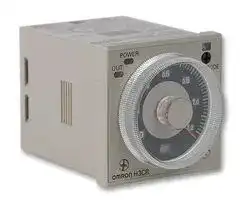


H3CR-A 100-240VAC/100-125VDC
Analogue Timer, On-Delay, 14 Ranges, 0.05 s, 300 h, 1 Changeover Relay
- Manufacturer: OMRON INDUSTRIAL AUTOMATION
- Product type: Analogue Timers
- Product Range:-; Timer Functions:On-Delay; No. of Timing Ranges:14Ranges; Time Min:0.05s; Time Max:300h; Timer Output:1 Changeover Relay; Supply Voltage Max:240VAC; Current Rating Nom:5A; Connection
- Time Max: 300h
- Time Min: 0.05s
- Timer Output: 1 Changeover Relay
- Product Range: -
- Timer Functions: On-Delay
- Current Rating Nom: 5A
- Panel Cutout Width: 45mm
- Supply Voltage Max: 240VAC
- Panel Cutout Height: 45mm
- No. of Timing Ranges: 14Ranges
- Connection / Termination: Plug-In
| Delivery and price | |
|---|---|
| Units per pack | 10 |
| Price | 70.87 € |
| Current stock | 10+ |
| Lead time | 30 days |
**Solid-state Multi-functional Timers H3CR-A**

CSM_H3CR-A_DS_E_6_2

## **Multiple Operating Modes and Multiple Time Ranges. DIN 48 x 48-mm Multifunctional Timer with Wide AC/DC Power Supply Range for Both High and Low Voltages.**

- A wide AC/DC power supply range greatly reduces the number of timer models kept in stock.

- A wide range of applications with multiple operating modes, six modes for 11-pin models and four modes for 8-pin models.

- Ecological design with reduced current consumption.

- Easy sequence checking with instantaneous outputs for a zero set value.

## LR

- Length of 80 mm or less when panel-mounted with a P3GA-11 Socket (H3CR-A8E, 100 to 240 VAC, 100 to 125 VDC)

- PNP input models available.

- Standards: UL, CSA, NK, LR, EN 61812-1, and CE Marking.

## **Model Number Structure**

## ■ **Model Number Legend**

**Note:** This model number legend includes combinations that are not available. Before ordering, please check the _List of Models_ on page 2 for availability.

**H3CR-A** @ @ @ **-** @ @ **1 2 3 4 5**

## **1. Number of Pins**

None: 11-pin models

- 8: 8-pin models

## **2. Input Type for 11-pin Models**

None: No-voltage input (NPN type)

- P: Voltage input (PNP type)

## **3. Output**

None: Relay output (DPDT)

- S: Transistor output (NPN/PNP universal use)

- E: Relay output (SPDT) with instantaneous relay output (SPDT)

## **4. Suffix**

- 300: Dual mode models (signal ON/OFF-delay and one-shot)

- 301: Double time scale (range) models (0.1 s to 600 h)

## **5. Supply Voltage**

100-240AC/100-125DC: 100 to 240 VAC/100 to 125 VDC 24-48AC/12-48DC: 24 to 48 VAC/12 to 48 VDC

- 24-48AC/DC: 24 to 48 VAC/VDC (Only for H3CR-A8E)

**1**

**H3CR-A**

## **Orderin Information g**

## ■ **List of Models**

**Note:** 1. Specify both the model number and supply voltage when ordering. Example: H3CR-A 100-240AC/100-125DC

Supply voltage

2. The operating modes are as follows

   - A: ON-delay D:  Signal OFF-delay B: Flicker OFF start E:  Interval B2:  Flicker ON start G:  Signal ON/OFF-delay C: Signal ON/OFF-delay J:  One-shot

## **11-pin Models**

|**11-pin Models**||||||
|---|---|---|---|---|---|
|**Output**|**Supply voltage**|**Input type**|**Time range**|**Operating mode**<br>**(See note 2)**|**Model**<br>**(See note 1.)**|
|**Contact**|100 to 240 VAC (50/60 Hz)/<br>100 to 125 VDC|No-voltage input|0.05 s to 300 h|Six multi-modes: A, B,<br>B2, C, D, E|H3CR-A|
||24 to 48 VAC (50/60 Hz)/<br>12 to 48 VDC|||||
||100 to 240 VAC (50/60 Hz)/<br>100 to 125 VDC|||Dual-modes: G, J|H3CR-A-300|
||24 to 48 VAC (50/60 Hz)/<br>12 to 48 VDC|||||
||100 to 240 VAC (50/60 Hz)/<br>100 to 125 VDC|Voltage input||Six multi-modes: A, B,<br>B2, C, D, E|H3CR-AP|
||24 to 48 VAC (50/60 Hz)/<br>12 to 48 VDC|||||
||100 to 240 VAC (50/60 Hz)/<br>100 to 125 VDC|No-voltage input|0.1 s to 600 h||H3CR-A-301|
||24 to 48 VAC (50/60 Hz)/<br>12 to 48 VDC|||||
|**Transistor**<br>**(Photocoupler)**|24 to 48 VAC (50/60 Hz)/<br>12 to 48 VDC||0.05 s to 300 h||H3CR-AS|


## **- 8 pin Models**

|**8-pin Models**||||||
|---|---|---|---|---|---|
|**Output**|**Supply voltage**|**Input type**|**Time range**|**Operating mode**<br>**(See note 2)**|**Model**<br>**(See note 1.)**|
|**Contact**|100 to 240 VAC (50/60 Hz)/<br>100 to 125 VDC|No-input available|0.05 s to 300 h|Four multi-modes: A,<br>B2, E, J<br>(Power supply start)|H3CR-A8|
||24 to 48 VAC (50/60 Hz)/<br>12 to 48 VDC|||||
||100 to 240 VAC (50/60 Hz)/<br>100 to 125 VDC||0.1 s to 600 h||H3CR-A8-301|
||24 to 48 VAC (50/60 Hz)/<br>12 to 48 VDC|||||
|**Transistor**<br>**(Photocoupler)**|24 to 48 VAC (50/60 Hz)/<br>12 to 48 VDC||0.05 s to 300 h||H3CR-A8S|
|**Time-limit contact and**<br>**instantaneous contact**|100 to 240 VAC (50/60 Hz)/<br>100 to 125 VDC||||H3CR-A8E|
||24 to 48 VAC/VDC (50/60 Hz)|||||


**2**

**H3CR-A**

## ■ **Accessories (Order Separately)**

## **Adapter, Protective Cover, Hold down Clip, Setting Ring and Panel Cover**

|**Name/specifications**|**Name/specifications**|**Models**|
|---|---|---|
|**Flush Mounting Adapter**||Y92F-30|
|||Y92F-73|
|||Y92F-74|
|**Protective Cover**||Y92A-48B|
|**Hold-down Clip (Sold in sets of**<br>**two)**|**For PF085A Socket**|Y92H-8|
||**For PL08 and PL11 Sockets**|Y92H-7|
|**Setting Ring A**||Y92S-27|
|**Setting Ring B and C**||Y92S-28|
|**Panel Cover**|**Lightgray (5Y7/1)**|Y92P-48GL|
||**Black(N1.5)**|Y92P-48GB|
||**Mediumgray (5Y5/1)**|Y92P-48GM|


## **Sockets**

|**Sockets**||||
|---|---|---|---|
|**Timer**||**Round Sockets**||
|**Pin**|**Connection**|**Terminal**|**Models**|
|11-pin|Front Connecting|DIN track mounting|**P2CF-11**|
|||DIN track mounting<br>(Finger-safe type)|**P2CF-11-E**|
||Back Connecting|Screw terminal|**P3GA-11**|
|||Solder terminal|**PL11**|
|||Wrappingterminal|**PL11-Q**|
|||PCB terminal|**PLE11-0**|
|8-pin|Front Connecting|DIN track mounting|**P2CF-08**|
|||DIN track mounting<br>(Finger-safe type)|**P2CF-08-E**|
|||DIN track mounting|**PF085A**|
||Back Connecting|Screw terminal|**P3G-08**|
|||Solder terminal|**PL08**|
|||Wrappingterminal|**PL08-Q**|
|||PCB terminal|**PLE08-0**|


**Note: 1.** The P2CF-@@-E has a finger-protection structure. Round crimp terminals cannot be used. Use forked crimp terminals.

**2.** The P3GA-11 and P3G-08 Socket can be used together with the Y92A-48G Terminal Cover to implement finger protection.

**3.** For details, refer to _Socket and DIN Track Products_ .

## **Terminal Cover**

|**Terminal Cover**|||
|---|---|---|
|**Application**|**Model**|**Remarks**|
|**For back connecting socket**|**Y92A-48G**|For P3G-08 and P3GA-11|


**Note:** For details, refer to _Socket and DIN Track Products_ .

**3**

**H3CR-A**

## **S ecifications p**

## ■ **General**

|■**General**|||||
|---|---|---|---|---|
|**Item**|**H3CR-A/-AS**|**H3CR-AP**|**H3CR-A8/-A8S**|**H3CR-A8E**|
|**Operating mode**|A:<br>ON-delay<br>B:<br>Flicker OFF start<br>B2: Flicker ON start<br>C: Signal ON/OFF-delay<br>D: Signal OFF-delay<br>E:<br>Interval<br>G: Signal ON/OFF-delay (Only for H3CR-A-300)<br>J:<br>One-shot (Only for H3CR-A-300)||A:<br>ON-delay (power supply start)<br>B2: Flicker ON start (power supply start)<br>E:<br>Interval (power supply start)<br>J:<br>One-shot (power supply start)||
|**Pin type**|11-pin||8-pin||
|**Input type**|No-voltage input|Voltage input|---||
|**Time-limit output type**|H3CR-A/-A8/-AP: Relay output (DPDT)<br>H3CR-AS/-A8S:<br>Transistor output (NPN/PNP universal)*|||Relay output (SPDT)|
|**Instantaneous output type**|---|||Relay output (SPDT)|
|**Mounting method**|DIN track mounting, surface mounting, and flush mounting||||
|**Approved standards**|UL508, CSA C22.2 No.14, NK, Lloyds<br>Conforms to EN61812-1 and IEC60664-1 (VDE0110) 4kV/2.<br>Output category according to EN60947-5-1 for Timers with Contact Outputs.<br>Output category according to EN60947-5-2 for Timers with Transistor Outputs.||||


*The internal circuits are optically isolated from the output. This enables universal application as NPN or PNP transistor.

## ■ **Time Ranges**

**Note:** When the time setting knob is turned below “0” until the point where the time setting knob stops, the output will operate instantaneously at all time range settings.

## **- - Standard (0.05 s to 300 h) Models**

|**Time unit**|**Time unit**|**s (sec)**|**min (min)**|**h (hrs)**|×**10 h (10 hrs)**|
|---|---|---|---|---|---|
|**Full scale**<br>**setting**|1.2|0.05 to 1.2|0.12 to 1.2||1.2 to 12|
||3|0.3 to 3|||3 to 30|
||12|1.2 to 12|||12 to 120|
||30|3 to 30|||30 to 300|
|**Double (0.1-s to 600-h) Models**||||||
|**Time unit**||**s (sec)**|**min (min)**|**h (hrs)**|×**10 h (10 hrs)**|
|**Full scale**<br>**setting**|2.4|0.1 to 2.4|0.24 to 2.4||2.4 to 24|
||6|0.6 to 6|||6 to 60|
||24|2.4 to 24|||24 to 240|
||60|6 to 60|||60 to 600|


**4**

**H3CR-A**

## ■ **Ratings**

|■**Ratings**||
|---|---|
|**Rated supply voltage (See notes 1, 2, and 5.)**|100 to 240 VAC (50/60 Hz)/100 to 125 VDC, 24 to 48 VAC (50/60 Hz)/12 to 48 VDC (24 to 48 VAC/VDC for H3CR-<br>A8E) (See note3.)|
|**Operating voltage range**|85% to 110% of rated supply voltage (90% to 110% at 12 VDC)|
|**Power reset**|Minimum power-opening time: 0.1 s|
|**Input**|No-voltage Input<br>ON impedance:<br>1 kΩmax.<br>ON residual voltage:<br>1 V max.<br>OFF impedance:<br>100 kΩmin.<br>Voltage Input<br>Max. permissible capacitance between inputs lines (terminals 6 and 7): 1,200 pF<br>Load connectable in parallel with inputs (terminals 6 and 7).<br>• 100 to 240 VAC/100 to 125 VDC<br>High (logic) level:<br>85 to 264 VAC/85 to 137.5 VDC<br>Low (logic) level:<br>0 to 10 VAC/0 to 10 VDC<br>• 24 to 48 VAC/12 to 48 VDC<br>High (logic) level:<br>20.4 to 52.8 VAC/10.8 to 52.8 VDC<br>Low (logic) level:<br>0 to 2.4 VAC/0 to 1.2 VDC|
|**Power consumption**|H3CR-A/-A8<br>• 100 to 240 VAC/100 to 125 VDC<br>(When at 240 VAC, 60 Hz)<br>Relay ON: approx. 2.0 VA (1.6 W)<br>Relay OFF: approx. 1.3 VA (1.1 W)<br>• 24 to 48 VAC/12 to 48 VDC<br>(When at 24 VDC)<br>Relay ON: approx. 0.8 W<br>Relay OFF: approx. 0.2 W<br>H3CR-AP<br> (See note 3)<br>• 100 to 240 VAC/100 to 125 VDC<br>(When at 240 VAC, 60 Hz)<br>Relay ON: approx. 2.5 VA (2.2 W) (See note 4.)<br>Relay OFF: approx. 1.8 VA (1.7 W) (See note 4.)<br>• 24 to 48 VAC/12 to 48 VDC<br>(When at 24 VDC)<br>Relay ON: approx. 0.9 W (See note 4.)<br>Relay OFF: approx. 0.3 W (See note 4.)<br>H3CR-A8E<br>• 100 to 240 VAC/100 to 125 VDC<br>(When at 240 VAC, 60 Hz)<br>Relay ON/OFF: approx. 2 VA (0.9 W)<br>• 24 to 48 VAC/VDC<br>(When at 24 VDC)<br>Relay ON/OFF: approx. 0.9 W<br>H3CR-AS/-A8S<br>• 24 to 48 VAC/12 to 48 VDC<br>(When at 24 VDC)<br>Output ON: 0.3 W Output OFF: 0.2 W|
|**Control outputs**|Time limit contacts:<br>5 A at 250 VAC/30 VDC, 0.15 A at 125 VDC, resistive load (cosφ= 1)<br>Transistor output:<br>Open collector (NPN/PNP), 100 mA max. at 30 VDC max.,<br>residual voltage: 2 V max.<br>Instantaneous contact: 5 A at 250 VAC/30 VDC, 0.15 A at 125 VDC, resistive load (cosφ= 1)|


- **Note: 1.** DC ripple rate: 20% max. (A single-phase, full-wave-rectification power supply can be used).

   **2.** Do not use an inverter output as the power supply. Refer to _Safety Precautions for All Timers_ for details.

   **3.** Models with 24-to-48-VAC or 12-to-48-VDC power supply have inrush current. Caution is thus required when turning ON and OFF power to the Timer with a non-contact output from a device such as a sensor. (Models with an inrush current of approximately 50 mA and a 24VDC power supply are available (the H3CR-A-302 and H3CR-A8-302).)

   **4.** The values are for when the terminals 2 and 7 and terminals 10 and 6 are short-circuited, and include the consumption current of the input circuit.

   **5.** Refer to _Safety Precautions for All Timers_ when using the Timer together with a 2-wire AC proximity sensor.

**5**

**H3CR-A**

## ■ **Characteristics**

|**Accuracy of operating**<br>**time**|±0.2% FS max. (±0.2%±10 ms max. in a range of 1.2 s or 3 s)|
|---|---|
|**Setting error**|±5% FS±50 ms (See note 1)|
|**Reset time**|Min. power-opening time: 0.1 s max.<br>Min. pulse width:<br>0.05 s (H3CR-A/-AS)|
|**Reset voltage**|10% max. of rated supplyvoltage|
|**Influence of voltage**|±0.2% FS max. (±0.2%±10 ms max. in a range of 1.2 s or 3 s)|
|**Influence of temperature**|±1% FS max. (±1%±10 ms max. in a range of 1.2 s or 3 s)|
|**Insulation resistance**|100 MΩmin.(at 500 VDC)|
|**Dielectric strength**|2,000 VAC (1,000 VAC for H3CR-A@S), 50/60 Hz for 1 min (between current-carrying metal parts and exposed non-<br>current-carrying metal parts)<br>2,000 VAC (1,000 VAC for H3CR-A@S), 50/60 Hz for 1 min (between control output terminals and operating circuit)<br>2,000 VAC, 50/60 Hz for 1 min (between contacts of different polarities)<br>1,000 VAC, 50/60 Hz for 1 min (between contacts not located next to each other)<br>2,000 VAC, 50/60 Hz for 1 min(between input and control output terminals and operation circuit)for H3CR-AP|
|**Impulse withstand**<br>**voltage**|3 kV (between power terminals) for 100 to 240 VAC/100 to 125 VDC, 1 kV for 24 to 48 VAC/12 to 48 VDC<br>4.5 kV (between current-carrying terminal and exposed non-current-carrying metal parts) for 100 to 240 VAC/100 to<br>125 VDC, 1.5 kV for 24 to 48 VAC/12 to 48 VDC and 24 to 48 VAC/VDC|
|**Noise immunity**|±1.5 kV (between power terminals) and±600 V (between no-voltage input terminals), square-wave noise by noise<br>simulator(pulse width: 100 ns/1μs, 1-ns rise)|
|**Static immunity**|Malfunction: 8 kV<br>Destruction: 15 kV|
|**Vibration resistance**|Destruction: 10 to 55 Hz with 0.75-mm single amplitude each in 3 directions for 2 hours each<br>Malfunction: 10 to 55 Hz with 0.5-mm single amplitude each in 3 directions for 10 minutes each|
|**Shock resistance**|Destruction: 1,000 m/s23 times each in 6 directions<br>Malfunction: 100 m/s23 times each in 6 directions|
|**Ambient temperature**|Operating:<br>−10°C to 55°C (with no icing)<br>Storage:<br>−25°C to 65°C (with no icing)|
|**Ambient humidity**|Operating:<br>35% to 85%|
|**Life expectancy**|Mechanical: 20,000,000 operations min. (under no load at 1,800 operations/h)<br>Electrical:<br>100,000 operations min. (5 A at 250 VAC, resistive load at 1,800 operations/h) (See note 2)|
|**EMC**|(EMI)<br>EN61812-1<br>Emission Enclosure:<br>EN55011 Group 1 class A<br>Emission AC Mains:<br>EN55011 Group 1 class A<br>(EMS)<br>EN61812-1<br>Immunity ESD:<br>IEC61000-4-2:<br>6 kV contact discharge (level 3)<br>8 kV air discharge (level 3)<br>Immunity RF-interference from AM Radio Waves:<br>IEC61000-4-3: 10 V/m (80 MHz to 1 GHz) (level 3)<br>Immunity RF-interference from Pulse-modulated Radio Waves:IEC61000-4-3: 10 V/m (900±5 MHz) (level 3)<br>Immunity Conducted Disturbance:<br>IEC61000-4-6:<br>10 V (0.15 to 80 MHz) (level 3)<br>Immunity Burst:<br>IEC61000-4-4:<br>2 kV power-line (level 3)<br>2 kV I/O signal-line (level 4)<br>Immunity Surge:<br>IEC61000-4-5:<br>1 kV line to line (level 3)<br>2 kV line toground(level 3)|
|**Case color**|Lightgray (Munsell 5Y7/1)|
|**Degree ofprotection**|IP40(panel surface)|
|**Weight**|Approx. 90g|


**Note: 1.** The value is ±5% FS +100 ms to −0 ms max. when the C, D, or G mode signal of the H3CR-AP is OFF.

**2.** Refer to the _Life-test Curve_ .

**3.** Relay output only.

## ■ **Life-test Curve**

**==> picture [160 x 150] intentionally omitted <==**

**----- Start of picture text -----**<br>
10,000<br>5,000<br>1,000 =S55E<br>NK —-——<br>30 VDC L/R = 7 ms<br>500<br>250 VAC/30 VDC<br>100 — SS (cos S φ = 1)<br>250 VAC (cosφ = 0.4)<br>0 1 2 3 |_|<br>Load current (A)<br>3)<br>Switching operations (x 10<br>**----- End of picture text -----**<br>


Reference: A maximum current of 0.15 A can be switched at 125 VDC (cosφ = 1) and a maximum current of 0.1 A can be switched if L/R is 7 ms. In both cases, a life of 100,000 operations can be expected. The minimum applicable load is 10 mA at 5 VDC (failure level: P).

**6** ~~a~~

**H3CR-A**

## **Connections**

## ■ **Block Diagrams**

## **H3CR-A/AS**

## **H3CR-AP**

**==> picture [335 x 414] intentionally omitted <==**

**----- Start of picture text -----**<br>
Zero setting<br>AC (DC) input detection  Time range/ Operating<br>unit selectors mode selector<br>circuit<br>Power supply  Oscillation  Counting<br>circuit circuit circuit Output circuit<br>Reset input, start input, and gate input Input circuit Indicator<br>circuit<br>Power-ON  Output-ON<br>indicator indicator<br>Zero setting<br>AC (DC) input detection  Time range/  Operating<br>unit selectors mode selector<br>circuit<br>Power supply  Oscillation  Counting<br>circuit circuit circuit Output circuit<br>Indicator<br>Start Input circuit<br>circuit<br>Power-ON  Output-ON<br>indicator indicator<br>**----- End of picture text -----**<br>


**7**

**H3CR-A**

**==> picture [512 x 549] intentionally omitted <==**

**----- Start of picture text -----**<br>
H3CR-A8/A8S<br>Zero setting<br>AC (DC) input detection  Time range/  Operating<br>unit selectors mode selector<br>circuit<br>Power supply  Oscillation  Counting<br>circuit circuit circuit Output circuit<br>Indicator<br>circuit<br>Power-ON  Output-ON<br>indicator indicator<br>H3CR-A8E<br>Zero setting<br>AC (DC) input detection  Time range/  Operating<br>unit selectors mode selector<br>circuit<br>Power supply  Oscillation  Counting<br>circuit circuit circuit Output circuit<br>Indicator<br>circuit<br>Power-ON  Output-ON<br>indicator indicator<br>Instantaneous<br>output circuit<br>■ I/O Functions<br>Inputs (for -A/ Start Starts time-measurement.<br>-AS models) Reset Interrupts time-measurement and resets time-measurement value. No time-measurement is made and<br>control output is OFF while the reset input is ON.<br>Gate Prohibits time-measurement.<br>Outputs Control output Outputs are turned ON according to designated output mode when preset value is reached.<br>**----- End of picture text -----**<br>


**Note:** H3CR-AP incorporates start input only.

**8**

**H3CR-A**

## ■ **Terminal Arrangement**

**Note:** The delayed contact of conventional Timers was indicated as

The contact symbol of the H3CR-A is indicated as

because its operating mode is six multi-modes (four multi-modes for the H3CR-A8).

## **11-pin Models**

## **- 8 pin Models**

## **H3CR-A/-A-300/-A-301 (Contact Output)**

**H3CR-A8/-A8-301 (Contact Output)**

**==> picture [193 x 200] intentionally omitted <==**

**----- Start of picture text -----**<br>
TopL een<br>(-\(-) Na Power supply<br>H3CR-AS (Transistor Output)<br>it<br>| °°.<br>| o © ¢<br>Reset input Start input Gate input<br>Reset input Start input Gate input<br>**----- End of picture text -----**<br>


**==> picture [50 x 9] intentionally omitted <==**

**----- Start of picture text -----**<br>
Power supply<br>**----- End of picture text -----**<br>


**==> picture [171 x 120] intentionally omitted <==**

**----- Start of picture text -----**<br>
H3CR-A8S (Transistor Output)<br>[- oot<br>| °°<br>eee<br>L.| pees!<br>Td Power supply<br>**----- End of picture text -----**<br>


**Note:** Terminals 1, 3, 4, and 5 are empty. Terminals 2 and 7 are the same as for the H3CR-A8.

**==> picture [174 x 126] intentionally omitted <==**

**----- Start of picture text -----**<br>
H3CR-A8E (Contact Output)<br>Le.<br>' i OA<br>Power supply<br>-——><br>**----- End of picture text -----**<br>


**==> picture [119 x 12] intentionally omitted <==**

**----- Start of picture text -----**<br>
Ct) Yo Power supply<br>**----- End of picture text -----**<br>


**Note:** Terminals 1, 3, 4, and 8 are empty. Terminals 2, 5, 6, 7, and 10 are the same as for the H3CR-A.

## **H3CR-AP (Contact Output)**

**==> picture [113 x 116] intentionally omitted <==**

**----- Start of picture text -----**<br>
? &<br>Or) 4G Power supply<br>Start input<br>**----- End of picture text -----**<br>


**Note: 1.** Terminal 5 is empty.

**2.** Separate power supplies can be used for the Timer and inputs.

**9** ~~a~~

**H3CR-A**

## ■ **Input Connections**

## **- - H3CR A/ AS**

The inputs of the H3CR-A/-AS are no-voltage (short-circuit or open) inputs.

## **No-voltage Inputs**

**==> picture [420 x 159] intentionally omitted <==**

**----- Start of picture text -----**<br>
No-contact Input Contact Input No-contact Input<br>(Connection to NPN open  (Connection to a voltage<br>collector output sensor.) output sensor.)<br>12 to 24 VDC  12 to 24 VDC<br>(sensor power supply) (sensor power supply)<br>+ − supplyDC power  + − supplyDC power<br>Timer Timer Timer<br>Sensor<br>Sensor<br>5 Gate 5 Gate 5 Gate<br>6 Start 6 Start 6 Start<br>7 Reset 7 Reset 7 Reset<br>2 Input (0 V) 2 Input (0 V) 2 Input (0 V)<br>Operates with transistor ON Operates with relay ON Operates with transistor ON<br>**----- End of picture text -----**<br>


## **No-voltage Input Signal Levels**

**==> picture [189 x 97] intentionally omitted <==**

**----- Start of picture text -----**<br>
No-contact  1. Short-circuit level<br>input Transistor ON<br>Residual voltage: 1 V max.<br>Impedance when ON: 1 kΩ max.<br>2. Open level<br>Transistor OFF<br>Impedance when OFF: 100 kΩ min.<br>Contact  Use contacts which can<br>input adequately switch 0.1 mA at 5 V<br>**----- End of picture text -----**<br>


**10**

**H3CR-A**

## **H3CR-AP**

The start input of the H3CR-AP is voltage input. (Voltage imposition or open)

**==> picture [484 x 213] intentionally omitted <==**

**----- Start of picture text -----**<br>
Voltage Inputs<br>No-contact Input No-contact Input Contact Input<br>(Connection to PNP open  (Connection to NPN open<br>collector output sensor) collector output sensor)<br>12 to 24 VDC  12 to 24 VDC<br>(sensor power supply) (sensor power supply)<br>+  DC power  +  DC power<br>− supply − supply<br>Sensor Sensor<br>Timer Timer<br>Timer<br>10 Power supply (+) 10 Power supply (+) 10 Power supply (+)<br>6 Start 6 Start 6 Start<br>7 Input 0V 7 Input 0V 7 Input 0V<br>2 Power supply  2 Power supply (−) 2 Power supply (−)<br>(−)<br>IB AB fin<br>Operates with PNP transistor ON Operates with NPN transistor ON Operates with relay ON<br>Note:    The input circuit is isolated from the  Note:  Refer to the signal levels in the<br>power supply circuit. Thus, an NPN  following table and be aware of the<br>transistor can be connected. minimum applicable load of the relay.<br>AC power supply DC power supply<br>**----- End of picture text -----**<br>


**Note:** Before making connections, refer to _Safety Precautions (H3CR-_ @ _)_ .

|No-contact<br>input|1. Transistor ON<br>Residual voltage: 1 V max.<br>The voltage between terminals 6 and 7 must be 10.8 VDC min.|
|---|---|
||2. Transistor OFF<br>Leakage current: 0.01 mA max.<br>The voltage between terminals 6 and 7 must be 1.2 VDC max.|
|Contact<br>input|Use contacts that can adequately switch 0.1 mA at each<br>operating voltage.<br>The voltage between terminals 6 and 7 with contacts ON or<br>OFF must satisfy the specified value.<br>Contacts ON<br>100-to-240-VAC and 100-to-125-VDC models: 85 to 264 VAC<br>or 85 to 137.5 VDC<br>24-to-48-VAC and 12-to-48-VDC models: 20.4 to 52.8 VAC or<br>10.8 to 52.8 VDC<br>Contacts OFF<br>100-to-240-VAC and 100-to-125-VDC models: 0 to 10 VAC or<br>0 to 10 VDC<br>24-to-48-VAC and 12-to-48-VDC models: 0 to 2.4 VAC or 0 to<br>1.2 VDC|


**11**

**H3CR-A**

## **O eration p**

## ■ **Timing Chart**

- **Note: 1.** The minimum power-opening time (“Rt”) is 0.1 s.

   **2.** The minimum input pulse width (for start, reset) is 0.05 s.

   **3.** The letter “t” in the timing charts stands for the set time and “t–a” means that the period is less than the time set.

   **4.** Power supply start in mode J is also possible for H3CR-A8/-A8E/-A8S/-A8-301 models.

   **5.** Refer to page 17 for application examples.

## **H3CR-A/-AS/-AP***

*H3CR-AP model incorporates start input only.

**==> picture [489 x 443] intentionally omitted <==**

**----- Start of picture text -----**<br>
Operating  Timing chart<br>mode<br>A: ON-delay Power t am: er t Ce Basic operation<br>Power<br>Start = a S e<br>Reset Start<br>ee ee ee (See note) i t<br>Output relay (NC)<br>maa LoL z Output _ eee<br>Output relay (NO)<br>(Output indicator) Note:  Start input is invalid while the<br>Power indicator Timer is in operation.<br>B:<br>Flicker OFF  Basic operation<br>Power<br>start Power<br>Start<br>Reset Start<br>(See note) t t t t<br>Output relay (NC)<br>Output<br>Output relay (NO)<br>(Output indicator) Note:  Start input is invalid while<br>Power indicator the Timer is in operation.<br>B2:<br>Flicker ON  Basic operation<br>start Power<br>Power<br>Start<br>Reset Start<br>Output relay (NC) (See note) t t t t<br>Output<br>Output relay (NO)<br>(Output indicator) Note:  Start input is invalid while the<br>Power indicator Timer is in operation.<br>C:<br>t ‘ t—a act t—a t—a i<br>Signal ON/ Basic operation<br>OFF-delay Power<br>Power<br>Start ee ——— ee<br>Reset Start<br>2 a | = YY (See note) t t t | t<br>Output relay (NC) Output<br>(Output indicator)Output relay (NO)  Note:  Start input is valid and<br>Power indicator bps pennlet eer atmbes oe bo eo nenmtet en ber exes en eamee retriggerable while the Timer<br>is in operation.<br>**----- End of picture text -----**<br>


**12**

**H3CR-A**

||**H3CR-A**|
|---|---|
|**Operating**<br>**mode**|**Timing chart**|
|D:<br>Signal OFF-<br>delay|t<br>Basic operation<br>Power<br>Output<br>Output relay (NC)<br>Power indicator<br>Power<br>Start<br>Reset<br>Output relay (NO)<br>(Output indicator)<br>Start<br>(See note)<br>**Note:**Start input is valid and<br>retriggerable while the<br>Timer is in operation.|
|E:<br>Interval|t<br>Power<br>Start<br>Reset<br>Output relay (NC)<br>Power indicator<br>Power<br>Output<br>Output relay (NO)<br>(Output indicator)<br>Basic operation<br>Start<br>(See note)<br>**Note:**Start input is valid and<br>retriggerable while the<br>Timer is in operation.<br>ns<br>f____|
|G:<br>Signal ON/<br>OFF-delay|t<br>t<br>t<br>t<br>Basic operation<br>Power<br>Output<br>Power<br>Start<br>Reset<br>Output relay (NC)<br>Power indicator<br>Output relay (NO)<br>(Output indicator)<br>Start<br>(See note)<br>**Note:**Start input is valid and<br>retriggerable while the Timer<br>is in operation.|
|J:<br>One-shot<br>output|t<br>Basic operation<br>Output<br>Power<br>Power<br>Start<br>Reset<br>Output relay (NC)<br>Power indicator<br>Output relay (NO)<br>(Output indicator)<br>1±0.6 s<br>(Fixed)<br>1±0.6 s<br>(Fixed)<br>Start<br>(See note)<br>1±0.6 s<br>(Fixed)<br>**Note:**Start input is valid and<br>retriggerable while the<br>Timer is in operation.<br>(Previous start input will<br>be cancelled.)<br>o_|<br>|e<br>.<br>es<br>a<br>esoe:<br>—_<br>Lard<br>Cw<br>pd|


## **Gate Signal Input**

|||t1|t2|
|---|---|---|---|
|Power|ON<br>OFF|EeeGaga Sere<br>rr||
|Start|ON|||
||OFF|||
|Gate|ON|||
||OFF|||
|Reset|ON|||
||OFF|||
|Output|ON|||
|relay|OFF|||


**Note:** 1. This timing chart indicates the gate input in operating mode A (ON-delay operation).

2. The set time is the sum of t1 and t2.

3. H3CR-AP model incorporates start input only.

**13**

**H3CR-A**

## **- - H3CR A8/ A8S**

**==> picture [477 x 366] intentionally omitted <==**

**----- Start of picture text -----**<br>
Operating  Timing chart<br>mode<br>A:  ¢ Rt t Rt t=a<br>ON-delay cod<br>Power Ee ees ee fe | Basic operation<br>Output relay<br>(NC) Power<br>Output relay  t<br>(NO) (output<br>indicator) Output<br>Power<br>indicator<br>B2: ta At ta<br>Flicker ON  a ee Aa NO<br>start Power Basic operation<br>mmm eee Co<br>Output relay<br>(NC) oem eee ee Power e e<br>Output relay  t t t t<br>(NO) (output<br>indicator) Output<br>Power<br>indicator v<br>E:<br>Interval im t Rt at Rt t—a<br>Power<br>Basic operation<br>Output relay<br>(NC) r~*« Power e e<br>Output relay  t<br>(NO) (output<br>indicator) Output<br>Power<br>indicator<br>J: Rt ta Rt<br>One-shot  —<br>output Power<br>Basic operation<br>Output relay<br>(NC)<br>1±0.6  s  1±0.6 s  Power<br>Output relay  ei (Fixed) | (Fixed) e e<br>(NO) (output indicator)Power  Output t 1(Fixed)±0.6 s<br>indicator<br>**----- End of picture text -----**<br>


**Note: 1.** The minimum power-opening time (“Rt”) is 0.1 s.

**2.** The letter “t” in the timing charts stands for the set time and “t–a” means that the period is less than the time set.

**14**

**H3CR-A**

## **- H3CR A8E**

|**Operating**<br>**mode**|**Timing chart**|
|---|---|
|A:<br>ON-delay|t<br>Power<br>Power indicator<br>Power<br>Output<br>Basic operation<br>Output relay (NC)<br>Output relay (NO)<br>(output indicator)<br>Instantaneous<br>output relay (NC)<br>Instantaneous<br>output relay (NO)<br>ay<br>Rt<br>;<br>Rt<br>t—a<br>oo Lo<br>|<br>if<br>if<br>|<br>~~—~~—<br>ee<br>ee<br>|<br>pou<br>ij|
|B2:<br>Flicker ON<br>start|t<br>t<br>t<br>t<br>Power<br>Power indicator<br>Power<br>Output<br>Basic operation<br>Output relay (NC)<br>Output relay (NO)<br>(output indicator)<br>Instantaneous<br>output relay (NC)<br>Instantaneous<br>output relay (NO)<br>t<br>t<br>ta<br>Rt<br>i<br>'<br>t<br>ta<br>[i<br>a|
|E:<br>Interval|t<br>Power<br>Output<br>Basic operation<br>Power<br>Power indicator<br>Output relay (NC)<br>Output relay (NO)<br>(output indicator)<br>Instantaneous<br>output relay (NC)<br>Instantaneous<br>output relay (NO)<br>Rt<br>i<br>Rt<br>t-a<br>ee<br>=} —________esl} _______faiet —+ :<br>eee eee|
|J:<br>One-shot<br>output|t<br>Power<br>Power indicator<br>Power<br>Output<br>Basic operation<br>(Fixed)<br>(Fixed)<br>Output relay (NC)<br>Output relay (NO)<br>(output indicator)<br>Instantaneous<br>output relay (NC)<br>Instantaneous<br>output relay (NO)<br>1±0.6 s<br>(Fixed)<br>Rt<br>ta<br>Rt<br>—<br>—olT—eee—=—eaeaoaoeeo<br>Eee<br>ie ee<br>0<br>eeee<br>eee<br>Zz|


**Note: 1.** The minimum power-opening time (“Rt”) is 0.1 s.

**2.** The letter “t” in the timing charts stands for the set time and “t–a” means that the period is less than the time set.

## **Nomenclature**

Power indicator (green) (Flashes when Timer operates; lit when Timer stops operating)

Operating mode display window

Operating mode selector Select a mode from: A, B, B2, C, D, and E (H3CR-A, -AP, and -AS) A, B2, E and J (H3CR-A8, -A8S, and -A8E) G and J (H3CR-A-300)

Output indicator (orange) (Lit when output)

Scale range display windows

Time range selector (select one from 1.2, 3, 12, and 30 at full Lemon Hace scale; with the H3CR-A@-301, select from 2.4, 6, 24, or 60 at Time setting full scale.) knob (set time)

Time unit display window

Time unit selector (select one from sec, min, hrs, and 10h)

**15**

**H3CR-A**

## **Dimensions**

**Note:** All units are in millimeters unless otherwise indicated.

**==> picture [411 x 335] intentionally omitted <==**

**----- Start of picture text -----**<br>
H3CR-A<br>H3CR-AP  15 66.6<br>H3CR-AS 6 52.3<br>48 0.7<br>ae & j =<br>—=- l 48 aa 39 dia. | i : 44.8 × 44.8<br>11 pins<br>H3CR-A8<br>H3CR-A8S<br>15<br>H3CR-A8E 66.6<br>6 52.3<br>48 0.7<br>oo 48 TA 39 dia. oma 44.8 × 44.8<br>)! coy l t<br>8 pins<br>Dimensions with Set Ring 16.5<br>50<br>50 42 dia.<br>sadFanese, | |W”, <e,> oy i=<br>a KR ) Z) Ms ors»<br>Time Setting  Panel cover<br>Ring<br>**----- End of picture text -----**<br>


**Dimensions with Front Connecting Socket P2CF-08-** @ **/P2CF-11-** @

**Dimensions with Back Connecting Socket P3G-08/P3GA-11**

**==> picture [472 x 104] intentionally omitted <==**

**----- Start of picture text -----**<br>
el LS eeimeeaieme ee 15 81.580 , 15 rans 7581.5 ee<br>H3CR-A  H3CR-A8@<br>100.8* H3CR-AS H3CR-AP 98.5 89.9* 87.6 H3CR-A H3CR-AS H3CR-AP  H3CR-A8 + Adapter@<br>+<br>Adapter<br>P3GA-11 P3G-08<br>" ea Y92F-30 Y92F-30<br>(When  (When<br>P2CF-11 2.3* P2CF-08 2.3* Y92A-48G  Y92A-48G<br>P2CF-11-E P2CF-08-E mounted) mounted)<br>**----- End of picture text -----**<br>


*These dimensions vary with the kind of DIN track (reference value).

**16**

**H3CR-A**

**A lication Exam les H3CR-A pp p ( )**

## **- A Mode: ON delay**

ON-delay operation (A mode) is a basic mode.

## **3. Control of Integrated Time with Gate Signal**

## **1. Power-ON Start/Power-OFF Reset**

The Power-ON start/Power-OFF reset operation is a standard operating method.

With a gate signal, the Power-ON start operation and Signal start operation can be controlled (the operation can be interrupted).

**==> picture [167 x 211] intentionally omitted <==**

**----- Start of picture text -----**<br>
t<br>Power (2 and 10)<br>Start (2 and 6)<br>Reset (2 and 7)<br>Control output: NC (8 and 11)<br>NC (1 and 4)<br>Control output: NO (9 and 11)<br>NO (1 and 3)<br>Power indicator<br>Flashing Lit<br>Externally short-circuited<br>%<br>mnonl [al]<br>Power<br>supply<br>—<br>**----- End of picture text -----**<br>


**==> picture [211 x 212] intentionally omitted <==**

**----- Start of picture text -----**<br>
t1 t2 t1 + t2: set time<br>Power (2 and 10)<br>Start (2 and 6) oe<br>Gate (2 and 5)<br>Control output: NC (8 and 11)<br>NC (1 and 4) |<br>Control output: NO (9 and 11)<br>NO (1 and 3)<br>Power indicator Seats denen<br>Flashing Lit<br>Gate signal (The operation is interrupted with the<br>gate signal if the Timer detects an abnormal signal.)<br>o™O<br>Externally<br>short-circuited<br>|<br>eas |<br>Power<br>= supply<br>**----- End of picture text -----**<br>


## **2. Signal Start/Signal Reset**

The Signal start/Signal reset operation is useful for remote control of the Timer.

## **B/B2 Mode: Flicker**

The flicker operation in the B and B2 modes can be effectively applied to lamp or buzzer (ON and OFF) alarms or the monitoring of an intermittent operation with a display.

**==> picture [191 x 98] intentionally omitted <==**

**----- Start of picture text -----**<br>
Power (2 and 10)<br>Start (2 and 6)<br>Reset (2 and 7)<br>Control output: NC (8 and 11)<br>NC (1 and 4)<br>Control output: NO (9 and 11)<br>NO (1 and 3)<br>Power indicator<br>Lit Flashing Lit<br>**----- End of picture text -----**<br>


## **1. Power-ON Start/Power-OFF Reset (in B Mode)**

Power (2 and 10) Start (2 and 6) Lit Flashing Lit Control output: NC (8 and 11) NC (1 and 4) ~~-~~ Start signal (remote control possible) Control output: NO (9 and 11)   NO (1 and 3) ~~=~~ Reset signal (remote control possible) Power indicator | cama Flashing Externally short-circuited Power supply (Power continuously supplied) ~~y~~ s

**==> picture [20 x 13] intentionally omitted <==**

**----- Start of picture text -----**<br>
Power<br>supply<br>**----- End of picture text -----**<br>


**17**

**H3CR-A**

## **2. Signal Start/Signal Reset (in B Mode)**

If there is an abnormal signal, flashing starts. When the abnormal condition is restored, a reset signal stops the display flashing.

**==> picture [15 x 4] intentionally omitted <==**

**----- Start of picture text -----**<br>
t t<br>**----- End of picture text -----**<br>


**==> picture [219 x 211] intentionally omitted <==**

**----- Start of picture text -----**<br>
Power (2 and 10)<br>Start (2 and 6) :<br>Reset (2 and 7) Pooh<br>Control output: NC (8 and 11)    =F=—"s"_" :<br>NC (1 and 4)<br>Control output: NO (9 and 11)<br>NO (1 and 3)<br>Power indicator<br>Lit Flashing Lit<br>D o Start signal<br>Reset signal<br>O O ad<br>5 1 Od.<br>ee Power<br>supply<br>(Power continuously supplied)<br>**----- End of picture text -----**<br>


## **- C Mode: Signal ON/OFF delay**

The Signal ON-/OFF-delay operation (C mode) is useful for the control of distribution of products on a production line into boxes by the specified number or time.

## **1. Power-ON Start/Instantaneous Operation/ Time-limit Reset**

A set of these functions is useful for the operation of a machine for a specified period when power is ON.

**==> picture [199 x 191] intentionally omitted <==**

**----- Start of picture text -----**<br>
t t<br>Power (2 and 10)<br>Start (2 and 6)<br>Control output: NC (8 and 11)<br>NC (1 and 4)<br>Control output: NO (9 and 11)<br>NO (1 and 3)<br>Power indicator<br>Flashing Lit Flashing Lit<br>Externally short-circuited<br>6<br>oO<br>» oe; [2<br>2 10.<br>mania Power  >a<br>supply<br>**----- End of picture text -----**<br>


## **2. Signal-ON-OFF Start/Instantaneous Operation/Time-limit Reset**

**==> picture [225 x 212] intentionally omitted <==**

**----- Start of picture text -----**<br>
Power (2 and 10)<br>Start (2 and 6)<br>Control output: NC (8 and 11)    Ze | eee<br>NC (1 and 4)<br>Control output: NO (9 and 11)   NO (1 and 3) S|ee<br>ee<br>Power indicator<br>Start signal<br>(The operation starts with the signal ON or OFF)<br>2 2.<br>b 50"4, %<br>LT? 5 & fe<br>Power<br>supply<br>| |<br>(Power continuously supplied)<br>Lit Flashing Lit Flashing Lit Flashing Lit<br>**----- End of picture text -----**<br>


## **- D Mode: Signal OFF delay**

Signal OFF-delay operation (D mode) can be effectively used to keep a load operating for a certain period. For example, this function enables the cooling fan for a lamp or heater to operate for a certain period after the lamp or heater is switched OFF.

## **1. Power-ON Start/Instantaneous Operation/ Time-limit Reset**

**==> picture [208 x 82] intentionally omitted <==**

**----- Start of picture text -----**<br>
Power (2 and 10)<br>Start (2 and 6)<br>Control output: NC (8 and 11)<br>NC (1 and 4)<br>Control output: NO (9 and 11)<br>NO (1 and 3)<br>Power indicator<br>Lit Flashing Lit<br>**----- End of picture text -----**<br>


**==> picture [73 x 75] intentionally omitted <==**

**----- Start of picture text -----**<br>
Start signal (NC to NO)<br>dit)<br>mata<br>Power<br>supply<br>**----- End of picture text -----**<br>


**18**

**H3CR-A**

## **2. Signal Start/Instantaneous Operation/ Time-limit Reset**

**==> picture [205 x 198] intentionally omitted <==**

**----- Start of picture text -----**<br>
Power (2 and 10)<br>Start (2 and 6)<br>Control output: NC (8 and 11)<br>NC (1 and 4)<br>Control output: NO (9 and 11)<br>NO (1 and 3)<br>Power indicator<br>Lit Flashing Lit<br>Start signal (NO to NC to NO)<br>fg O Bp<br>Power<br>aT supply<br>(Power continuously supplied)<br>**----- End of picture text -----**<br>


## **E Mode: Interval**

## **2. Signal Start/Instantaneous Operation/ Time-limit Reset**

This function is useful for the repetitive control such as the filling of liquid for a specified period after each Signal start input.

**==> picture [203 x 199] intentionally omitted <==**

**----- Start of picture text -----**<br>
t t<br>Power (2 and 10)<br>Start (2 and 6)<br>Control output: NC (8 and 11)<br>NC (1 and 4)<br>Control output: NO (9 and 11)<br>NO (1 and 3)<br>Power indicator<br>Flashing Lit Flashing Lit<br>Start signal<br>5 1<br>“iy i<br>nawtnaa£3<br>Power<br>oT supply<br>(Power continuously supplied)<br>**----- End of picture text -----**<br>


## **1. Power-ON Start/Instantaneous Operation/ Time-limit Reset**

This function is useful for the operation of a machine for a specified period after power is ON.

**==> picture [200 x 183] intentionally omitted <==**

**----- Start of picture text -----**<br>
t t<br>Power (2 and 10)<br>Start (2 and 6)<br>Control output: NC (8 and 11)<br>NC (1 and 4)<br>Control output: NO (9 and 11)<br>NO (1 and 3)<br>Power indicator<br>Flashing Lit Flashing Lit<br>Externally short-circuited<br>= Power supply<br>**----- End of picture text -----**<br>


**19**

**H3CR-A**

## **Safety Precautions (H3CR-A)**

Refer to _Safety Precautions for All Timers_ .

**Note:** The following precautions apply to all H3CR-A models.

## ■ **Power Supplies**

## ■ **Input/Output**

For the power supply of an input device of the H3CR-A@/-A@S/-AP, use an isolating transformer with the primary and secondary windings mutually isolated and the secondary winding not grounded.

**Relationship between Input and Power -** ~~—~~ **Supply Circuits (except for H3CR A8E)** The H3CR-A (except for H3CR-A8E) uses transformerless power supply. When connecting a relay or transistor as an external signal input device, pay attention to the following points to prevent shortcircuiting due to a sneak current to the transformerless power supply. If a relay or transistor is connected to two or more Timers, the input terminals of those Timers must be wired properly so that they will not differ in phase, otherwise the terminals will be short-circuited to one differ in phase, otherwise the terminals will be short-circuited to one another.

## **Correct**

**==> picture [441 x 325] intentionally omitted <==**

**----- Start of picture text -----**<br>
H3CR-A input device, pay attention to the following points to prevent short-<br>G,5, S,6, R7 10 circuiting due to a sneak current to the transformerless power supply.<br>Input  If a relay or transistor is connected to two or more Timers, the input<br>2 terminal 2 Power supply terminals of those Timers must be wired properly so that they will not differ in phase, otherwise the terminals will be short-circuited to one<br>another.<br>Incorrect Short-circuit current<br>H3CR-A<br>Contact or transistor for<br>external input signal<br>Input<br>Isolation transformer is required. terminal Power supply<br>Input device<br>OF at i<br>H3CR-A<br>G, S, R<br>5, 6, 7 10 Input<br>Input  terminal<br>terminal Power<br>2  2 supply<br>Correct<br>Input<br>terminal Power supply<br>Input device Isolation<br>transformer<br>@S/AP’s power supply terminal 2 is a common ter-S/AP’s power supply terminal 2 is a common ter-<br>D y te<br>Input<br>terminal<br>cme<br>**----- End of picture text -----**<br>


## **Incorrect**

The H3CR-A@/-A@S/AP’s power supply terminal 2 is a common ter-S/AP’s power supply terminal 2 is a common terminal for input signals to the Timer. Do not disconnect the wires on terminal 2, otherwise the internal circuitry of the Timer will be damaged.

It is impossible to provide two independent power switches as shown below regardless of whether or not the Timers are different in phase.

**==> picture [82 x 71] intentionally omitted <==**

**----- Start of picture text -----**<br>
10<br>5, 6, 7<br>G, S, R<br>Input terminal<br>H3CR-A<br>2<br>**----- End of picture text -----**<br>


**==> picture [128 x 70] intentionally omitted <==**

**----- Start of picture text -----**<br>
terminalInput  Power supply<br>Input<br>terminal<br>**----- End of picture text -----**<br>


Make sure that the voltage is applied within the specified range, otherwise the internal elements of the Timer may be damaged.

**20** ~~a~~

**H3CR-A**

## **Relationship between Input and Power** ~~OS~~ **Supply Circuits (H3CR-A** @ **/-A** @ **S)**

If a relay or transistor is connected to two or more Timers, the input terminals of those Timers must be wired properly so that they will not be different in phase or the terminals will be short-circuited to one another (refer to the figures below).

An appropriate input is applied to the input signal terminals of the H3CR-A@/-A@S when one of the input terminals is short-circuited with the common terminal (terminal 2) for the input signals. Never use terminal 10 as the common terminal for this purpose, otherwise the internal circuit of the Timer will be damaged.

**==> picture [489 x 385] intentionally omitted <==**

**----- Start of picture text -----**<br>
Incorrect Contact or transistor for<br>with the common terminal (terminal 2) for the input signals. Never  external input signal<br>use terminal 10 as the common terminal for this purpose, otherwise<br>the internal circuit of the Timer will be damaged. 10<br>6<br>Incorrect H3CR-AP Power supply<br>7<br>10<br>2<br>H3CR-A<br>AC or DC  5, 6, 7<br>power supply G, S, R 10<br>Input terminal 2 6<br>Short-circuit current<br>H3CR-AP<br>7<br>Correct 2<br>10<br>5, 6, 7G, S, R Correct Contact or transistor for<br>external input signal<br>Input terminal<br>H3CR-A<br>AC or DC  10<br>power supply 6<br>2 H3CR-AP Power supply<br>7<br>2<br>Do not connect a relay or any other load between input terminals,<br>otherwise the internal circuit of the Timer will be damaged due to the<br>high-tension voltage applied to the input terminals. Short-circuit current<br>10<br>6<br>10<br>H3CR-AP<br>Ry 7<br>H3CR-A<br>AC or DC  5, 6, 7 2<br>power supply G, S, R il<br>Input terminal<br>2<br>Input contact Common to All H3CR-A Models<br>**----- End of picture text -----**<br>


**==> picture [37 x 7] intentionally omitted <==**

**----- Start of picture text -----**<br>
Incorrect<br>**----- End of picture text -----**<br>


Do not connect a relay or any other load between input terminals, otherwise the internal circuit of the Timer will be damaged due to the high-tension voltage applied to the input terminals.

With the H3CR-AP, input wires must be as short as possible. If the floating capacity of wires exceeds 1,200 pF (approx. 10 m for cables with 120 pF/m), the operation will be affected. Pay particular attention when using shielded cables.

## **Relationship between Input and Power - Supply Circuits (H3CR AP)**

The H3CR-A@S transistor output is isolated from the internal circuitry by a photocoupler. Therefore, either NPN or PNP output is possible.

**==> picture [121 x 36] intentionally omitted <==**

**----- Start of picture text -----**<br>
H3CR-AP<br>AC/DC<br>supplypower  Input circuit Power supply circuit<br>**----- End of picture text -----**<br>


Since the input circuit and the power supply circuit are configured independently, the input circuit can be turned ON or OFF irrespective of the ON/OFF state of the power supply.

It must be noted that a voltage equivalent to the power supply voltage is applied to the input circuit.

ALL DIMENSIONS SHOWN ARE IN MILLIMETERS. ~~TTT~~ To convert millimeters into inches, multiply by 0.03937. To convert grams into ounces, multiply by 0.03527.

In the interest of product improvement, specifications are subject to change without notice.

**21**

## **Read and Understand This Catalog**

Please read and understand this catalog before purchasing the products. Please consult your OMRON representative if you have any questions or comments.

## **Warranty and Limitations of Liability**

- **WARRANTY** OMRON's exclusive warranty is that the products are free from defects in materials and workmanship for a period of one year (or other period if specified) from date of sale by OMRON.

OMRON MAKES NO WARRANTY OR REPRESENTATION, EXPRESS OR IMPLIED, REGARDING NON-INFRINGEMENT, MERCHANTABILITY, OR FITNESS FOR PARTICULAR PURPOSE OF THE PRODUCTS.  ANY BUYER OR USER ACKNOWLEDGES THAT THE BUYER OR USER ALONE HAS DETERMINED THAT THE PRODUCTS WILL SUITABLY MEET THE REQUIREMENTS OF THEIR INTENDED USE.  OMRON DISCLAIMS ALL OTHER WARRANTIES, EXPRESS OR IMPLIED.

**==> picture [479 x 32] intentionally omitted <==**

**----- Start of picture text -----**<br>
LIMITATIONS OF LIABILITY<br>OMRON SHALL NOT BE RESPONSIBLE FOR SPECIAL, INDIRECT, OR CONSEQUENTIAL DAMAGES, LOSS OF PROFITS OR COMMERCIAL LOSS<br>IN ANY WAY CONNECTED WITH THE PRODUCTS, WHETHER SUCH CLAIM IS BASED ON CONTRACT, WARRANTY, NEGLIGENCE, OR STRICT<br>LIABILITY.<br>**----- End of picture text -----**<br>


In no event shall the responsibility of OMRON for any act exceed the individual price of the product on which liability is asserted. IN NO EVENT SHALL OMRON BE RESPONSIBLE FOR WARRANTY, REPAIR, OR OTHER CLAIMS REGARDING THE PRODUCTS UNLESS OMRON'S ANALYSIS CONFIRMS THAT THE PRODUCTS WERE PROPERLY HANDLED, STORED, INSTALLED, AND MAINTAINED AND NOT SUBJECT TO CONTAMINATION, ABUSE, MISUSE, OR INAPPROPRIATE MODIFICATION OR REPAIR.

## **Application Considerations**

- **SUITABILITY FOR USE** OMRON shall not be responsible for conformity with any standards, codes, or regulations that apply to the combination of products in the customer's application or use of the products. At the customer's request, OMRON will provide applicable third party certification documents identifying ratings and limitations of use that apply to the products.  This information by itself is not sufficient for a complete determination of the suitability of the products in combination with the end product, machine, system, or other application or use.

**==> picture [477 x 16] intentionally omitted <==**

**----- Start of picture text -----**<br>
The following are some examples of applications for which particular attention must be given.  This is not intended to be an exhaustive list of all possible<br>uses of the products, nor is it intended to imply that the uses listed may be suitable for the products:<br>**----- End of picture text -----**<br>


- Outdoor use, uses involving potential chemical contamination or electrical interference, or conditions or uses not described in this catalog. • Nuclear energy control systems, combustion systems, railroad systems, aviation systems, medical equipment, amusement machines, vehicles, safety equipment, and installations subject to separate industry or government regulations.

- Systems, machines, and equipment that could present a risk to life or property.

Please know and observe all prohibitions of use applicable to the products. NEVER USE THE PRODUCTS FOR AN APPLICATION INVOLVING SERIOUS RISK TO LIFE OR PROPERTY WITHOUT ENSURING THAT THE SYSTEM AS A WHOLE HAS BEEN DESIGNED TO ADDRESS THE RISKS, AND THAT THE OMRON PRODUCTS ARE PROPERLY RATED AND INSTALLED FOR THE INTENDED USE WITHIN THE OVERALL EQUIPMENT OR SYSTEM.

## **PROGRAMMABLE PRODUCTS**

OMRON shall not be responsible for the user's programming of a programmable product, or any consequence thereof.

## **Disclaimers**

**==> picture [508 x 188] intentionally omitted <==**

**----- Start of picture text -----**<br>
CHANGE IN SPECIFICATIONS<br>Product specifications and accessories may be changed at any time based on improvements and other reasons.<br>It is our practice to change model numbers when published ratings or features are changed, or when significant construction changes are made.<br>However, some specifications of the products may be changed without any notice.  When in doubt, special model numbers may be assigned to fix or<br>establish key specifications for your application on your request.  Please consult with your OMRON representative at any time to confirm actual<br>specifications of purchased products.<br>DIMENSIONS AND WEIGHTS<br>Dimensions and weights are nominal and are not to be used for manufacturing purposes, even when tolerances are shown.<br>PERFORMANCE DATA<br>Performance data given in this catalog is provided as a guide for the user in determining suitability and does not constitute a warranty. It may represent the<br>result of OMRON’s test conditions, and the users must correlate it to actual application requirements. Actual performance is subject to the OMRON<br>Warranty and Limitations of Liability.<br>ERRORS AND OMISSIONS<br>The information in this document has been carefully checked and is believed to be accurate; however, no responsibility is assumed for clerical,<br>typographical, or proofreading errors, or omissions.<br>2010.12<br>**----- End of picture text -----**<br>


**In the interest of product improvement, specifications are subject to change without notice.**

## **OMRON Corporation Industrial Automation Company**

**http://www.ia.omron.com/**

(c)Copyright OMRON Corporation 2010 All Right Reserved.
Updated at April 29, 2026
With a legacy spanning over 80 years, Omron Industrial Automation is a globally recognized leader in the manufacture of advanced industrial control and automation components. Renowned for their reliability and engineering excellence, Omron delivers comprehensive solutions that enhance efficiency, machine safety, and precision across a wide range of manufacturing environments. Our extensive portfolio of Omron products is heavily focused on their industry-leading sensing and switching technologies. We offer a vast selection of sensors, excelling specifically in high-performance proximity sensors, light sensors, and temperature sensors. Complementing this range are robust switching solutions, featuring a deep inventory of power relays, solid-state relays, safety relays, and essential relay accessories designed for demanding operational requirements. Beyond sensing and switching, Omron is highly regarded for its precision automation and process control equipment. Our selection features highly accurate temperature controllers, versatile process controllers, and sophisticated panel displays and instrumentation. To support these fundamental systems, we also supply dependable Omron power supplies, notably AC/DC converters, alongside vital connectivity components like DIN rail terminal blocks to ensure secure, efficient, and complete industrial setups.
About Novapart
Novapart is a B2B electronic component broker specialising in stock shortages and cost reduction. We source hard-to-find parts and identify compliant alternatives across a catalogue of 410,000+ components from 500+ manufacturers.
Learn more →Stock Shortage Specialist
When a component is unavailable, discontinued or has an unacceptable lead time, we tap into our network of vetted European and Asian distributors to source what you need — without compromising on quality or traceability.
Request a quote →Compliant Alternatives
We identify pin-to-pin, electrically equivalent substitutes that meet the same certifications (RoHS, AEC-Q100, REACH) as your original specification — validated against datasheets, not just part numbers. Often at a lower cost.
BOM Analysis service →