
Image not available
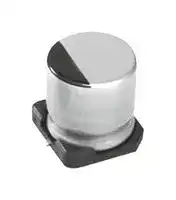
Illustrative purposes only

GYC1H101MCWADNGS
Hybrid Aluminium Electrolytic Capacitor, Vibration-Proof, 100 µF, ± 20%, 50 V, Radial Can - SMD
⚠️ Reference pricing provided. In case of supply shortages, we will connect you with our trusted procurement partners to ensure your project's continuity.
- Manufacturer: NICHICON
- Product type:
- ESR: 0.028ohm
- SVHC: No SVHC (16-Jul-2019)
- Capacitance: 100µF
- Voltage(DC): 50V
- Product Range: GYC Series
- Product Width: -
- Qualification: AEC-Q200
- Product Height: 10mm
- Product Length: -
- Product Diameter: 10mm
- Capacitance Tolerance: ± 20%
- Lifetime @ Temperature: 4000 hours @ 135°C
- Capacitor Case / Package: Radial Can - SMD
- Operating Temperature Max: 135°C
- Operating Temperature Min: -55°C
| Delivery and price | |
|---|---|
| Units per pack | 2000 |
| Price | 0.238 € |
| Current stock | 10+ |
| Lead time | 30 days |
Datasheet

Issue date Jan.09.2025

## NICHICON CORPORATION

NICHICON (IWATE) CORPORATION ENGINEERING DEPT.

## S P E C I F I C A T I O N O F

## CONDUCTIVE POLYMER HYBRID ALUMINUM ELECTROLYTIC CAPACITORS

## GYC series (Pb free)

|DWG.No.|G240617U3-A|DESIGNED.<br>~~i~~<br>~~[E~~|Jan.09.2025<br>~~i~~<br>~~apt~~<br>~~[E~~|
|---|---|---|---|
|||CHECKED<br>~~Ph~~<br>~~[E~~|Jan.09.2025<br>~~Ph~~<br>~~apt~~<br>~~[Etorensle~~|
|||APPROVED<br>~~[E~~|Jan.09.2025<br>~~apt~~<br>~~[Etorensle~~|


## REVISION

|MARK|DATE||REVISION|APPROVED|
|---|---|---|---|---|
|A|2025.1.9|Add REVISION sheet.||YAMAMOTO|
|||Sheet2|Change Voltage.||
|||Sheet2,6,7,10,11<br>Add Voltage 80V.|||
|||Sheet10|Add φ10×12.5L.||
|||Sheet10|Add ESR.||
|||Sheet11|Add Ripple current.||
|||Sheet20|Change a material of plastic platform.||


1. SCOPE This specification covers "GYC series" conductive polymer hybrid aluminum electrolytic capacitors. (JIS-32 TYPE)

2. APPLICABLE STANDARD Japanese Industrial Standard JIS C5101-4  Characteristics W and JIS C5101-1 except as specified in this specification.

3. OPERATING TEMPERATURE RANGE

Operating temperature range is the range of ambient temperature at which the capacitor can be operated continuously at rated voltage. -55 to +135degC

## 4. PERFORMANCE

Unless otherwise specified,the standard range of atmospheric conditions for making measurements and tests are as follows: Ambient temperature: 5 to 35degC Relative humidity  :45 to 85% Air pressure       :86kPa to 106kPa

If there may be doubt on the results, measurements shall be made within the following limits, Ambient temperature:20±2degC Relative humidity  :60 to 70% Air pressure       :86kPa to 106kPa

- G240617U3 A sheet 1

SPECIFICATION

DWG.№

|nichicon|nichicon|nichicon|nichicon|nichicon|nichicon|
|---|---|---|---|---|---|
|4.1<br>ELECTRICAL CHARACTERISTICS<br>No.<br>Item<br>Test   method<br>Performance<br>4.1.1 RATED VOLTAGE<br>DC 16~ 63 V<br>4.1.2 RATED CAPACITANCE<br>Measuring frequency    120Hz ±20 %<br>Measuring circuit      :<br>10~560μF<br>Series equivalent circuit<br>(<br>)<br>Capacitance tolerance:<br>Measuring voltage      :<br>±20%<br>0.5Vrms or less +1.5 to 2.0 VDC<br>4.1.3 tanδ<br>Measuring frequency, measuring circuit<br>Not more than the value<br>and measuring voltage are the same<br>given in table 1. <br>those for capacitance.<br>4.1.4 LEAKAGE CURRENT<br>The rated voltage shall be applied<br>across the capacitor and its<br>After<br>2 min;<br>protective resistor which shall be<br>not more than<br>1000±100Ω.The leakage current shall<br>16 to 63V:I=0.01CV(μA)<br>then be measured after an<br>80V:I=0.05CV(μA)<br>electrification period of 2 min.<br>I : Leakage current(μA)<br>Measurement circuit<br>C : Capacitance(μF)<br>V : Rated voltage(V)<br>Leakage current changes<br>depending on the<br>preprocessings and use<br>condition.Therefore, do<br>the voltage treatment<br>when there is a doubt.<br>(See sheet 19)<br>R : Protective resistor(1000±100Ω)<br>A: DC ammeter<br> V<br> : DC voltmeter<br>S : switch<br>S : Protective switch for an ammeter<br>C : Test Capacitor<br>4.1.5 ESR<br>at<br>100kHz±20%<br>Not more than the value<br>20℃±2℃<br>given in sheet 10(9.ESR)<br>4.1.6 TEMPERATURE<br>Step<br>Temperature<br>Time<br>Step 2 :<br>CHARACTERISTIC<br>1<br>20±2degC<br>------<br>Impedance ratio:<br>2<br>-25,-55<br>0<br>-3 degC<br>2h.<br>Ratio to the value at<br>3<br>20±2degC<br>15min.<br>step 1 shall be not<br>4<br>135<br>+3<br>0<br>degC<br>2h.<br>more than the value<br>given Table-1.<br>Step 1 :Capacitance and impedance<br>shall be measured.<br>Step 4 :<br>(|Z| 20degC 100kHz±20%)<br>Capacitance change:<br>Within ±30% of the<br>Step 2 :After the capacitor being<br>initial capacitance<br>stored for 2 hours,<br>value against Step.1<br>Impedance shall be made<br>at thermal stability.<br>(|Z| -25,-55degC 100kHz±20%)<br>Step 4 :After the capacitor being<br>stored for 2 hours,<br>capacitance shall be measured.<br>The measurement shall be made<br>at thermal stability.<br>80<br>1<br>2<br>X<br>A<br>S<br>R<br>S1<br>2<br>V<br>+<br>-<br>CX<br>+<br>-<br>A<br>A<br>~~a~~<br>se~~ee~~<br>~~a~~<br>~~a~~<br>~~ee~~<br>~~—~~<br>~~5~~<br>~~a ee ee~~<br>~~aes~~<br>~~a~~||||||
|SPECIFICATION<br>~~a~~|~~a~~|DWG.№|G240617U3-A|sheet|2|


~~a~~ SPECIFICATION

- DWG.№ G240617U3 A sheet 2

|№|Item|Test   method|Performance|
|---|---|---|---|
|4.1.7|SURGE TEST|Voltage application :<br>1000 times of charging for 30±5 sec.,<br>with a period of 6±0.5min..<br>Test temperature : 15 to 35degC<br>And the capacitor shall be stored under<br>standard atmospheric conditions to<br>obtain thermal stability, after which<br>measurements shall be made.|Capacitance<br>Not less than 80% of<br>the value before test.<br>tanδ:<br>200% or less the<br>initial specified value.<br>Leakage current:<br>Initial specified value<br>or less.|
|||Test circuit<br>R :Protective series resistor<br>(1000Ω)<br>v<br>:DC voltmeter<br>S :Switch<br>C :Test capacitor<br>Note :This requirement is applicable only to instantaneous<br>overvoltage which may be applied to the terminals of<br>capacitor, therefore, not applicable to such overvoltages<br>as often applied.<br>x<br>~~◯~~<br>V<br>+<br>-<br>X<br>C<br>S<br>R<br>+<br>-||


## 4.2 MECHANICAL PERFORMANCE

|№|Item|Test   method|Performance|
|---|---|---|---|
|4.2.1|RESISTANCE TO<br>VIBRATION|○Standard<br>As per JIS C 5101-1 4.17<br>Direction and duration of vibration:<br>3 orthogonal directions mutually each<br>for 2h. Total 6h.|When the capacitance is<br>measured, there shall be<br>no intermittent contacts,<br>or open or short-<br>circuiting.<br>There shall be no such<br>mechanical damage.<br>Appearance :<br>No remarkable<br>abnormality.|
|||○Vibration resistance<br>Acceleration:294 m/s2( 30G )<br>Frequency   :10 to 2000 Hz<br>Amplitude   :1.5mm max ( peak to peak ) <br>Direction and duration of vibration :<br>It is done in the X, Y, Z axis<br>direction for 2 hours each,<br>with a total of 6 hours.|When the capacitance is<br>measured, there shall be<br>no intermittent contacts,<br>or open or short-<br> circuiting.<br>There shall be no such<br>mechanical damage.<br>Appearance :<br>No remarkable<br>abnormality.|
|4.2.2|SOLDERABILITY|As per JIS C 5101-1 4.15<br>Temperature of solder<br>:235±5degC<br>Dipping time<br>:2±0.5 s<br>Storage time<br>:after 6 month termination shall be|At least 3/4 of<br>circumferential surface<br>of the dipped protion of<br>:after 6 month termination shall be<br>covered with new solder.|


SPECIFICATION ~~ee~~

DWG.№ ~~ee ee~~

- G240617U3 A sheet 3

## 4.3 ENDURANCE PERFORMANCE

|№|Item|Test   method|Performance|
|---|---|---|---|
|4.3.1|RESISTANCE OF<br>REFLOW|The reflow is done under reflow<br>condition on sheet 16.<br>After the capacitors are restored to<br>standard atmospheric conditions for<br>1 to 2 hours, the capacitors shall<br>meet the right requirements.|Capacitance change:<br>Within ±10% of the<br>initial capacitance<br>value.<br>tanδ:Initial specified<br>value or less.<br>ESR:130% or less of<br>initial specified value.<br>Leakage current :<br>Initial specified value<br>or less.<br>( Voltage treatment<br>(See sheet 19) )<br>Appearance :No remarkable<br>abnormality.|
|4.3.2|RESISTANCE<br>TO DAMP HEAT|Test temperature<br>:85±2degC<br>Relative humidity :85%<br>Test time<br>:2000<br>+72<br>-0 h<br>With rated voltage applied.<br>After restored to standard atmospheric<br>conditions, the capacitors shall meet<br>the right requirements.|Capacitance change:<br>Within ±30% of the<br>initial capacitance<br>value.<br>tanδ:200% or less the<br>initial specified value.<br>ESR:200% or less the<br>initial specified value.<br>Leakage current:<br>Initial specified value<br>or less.<br>Appearance :No remarkable<br>abnormality.|


~~a~~

- DWG.№ G240617U3 A sheet 4

SPECIFICATION

|nichicon|nichicon|nichicon|nichicon|nichicon|nichicon|
|---|---|---|---|---|---|
|№<br>Item<br>Test   method<br>Performance<br>4.3.3 LIFE TEST<br>As per JIS C 5101-1 4.23<br>Capacitance change:<br>Test temperature  :<br>±2degC<br>Within ±30% of the<br>:<br>±2degC<br>initial capacitance<br>Test time<br>:※1<br>h<br>value.<br>tanδ:200% or less the<br>The D.C. bias plus rated ripple current<br>initial specified value.<br>is applied (See sheet 11) for ※1 hours<br>ESR:200% or less the<br>at 135℃ or 125℃ the peak voltage shall<br>initial specified value.<br>not exceed the rated voltage.<br>Leakage current:<br>Initial specified value<br>※1<br>or less.<br>φ6.3<br>: 2000<br>+72<br>-0<br>Appearance :No remarkable<br>φ8、φ10<br>: 4000<br>+72<br>-0<br>abnormality.<br>4.3.4 SHELF LIFE<br>Test temperature<br>:<br>±2degC<br>Capacitance change:<br>TEST<br>Test time<br>:<br>+48<br>-0 h<br>Within ±30% of the<br>initial capacitance<br>value.<br>tanδ:200% or less the<br>initial specified value.<br>ESR:200% or less the<br>initial specified value.<br>Leakage current :Initial<br>specified value or less.<br>( Voltage treatment<br>according to<br>JIS C 5101-4 4.1 )<br>Appearance :No remarkable<br>abnormality.<br>4.3.5 PRESSURE RELIEF VENT<br>A.C. Application Test<br>The vent device is<br>TEST<br>The capacitor shall be subjected to<br>actuated under the test<br>(In case φ10×16.5)<br>an A.C. voltage(50 or 60Hz) with<br>conditions, thereby<br>r.m.s.value equal to 0.7 times<br>preventing terminals,<br>the rated D.C. voltage through<br>metal pieces, etc, of<br>a series resistor.<br>the capacitor from<br>The series resistor as follows.<br>scattering due to burst,<br>Cap.(μF)<br>R(Ω)<br>the case from separating<br>C≦10<br>100<br>from the seal packing,<br>10<C≦100<br>10<br>or the capacitor from<br>100<C≦1000<br>1<br>producing flame.<br>D.C. Application Test<br>The capacitor Shall be subjected to<br>a reverse D.C. voltage equal to the<br>rated D.C. voltage. The current<br>flowing through the capacitor shall<br>be limited to 1A.<br>Note :The test is terminated if the vent device is not actuated<br>when 30min. has elapsed from the start of the test conducted<br>under the conditions.<br>135<br>135<br>1000<br>125||||||
|SPECIFICATION<br>~~a~~||DWG.№|G240617U3-A|sheet|5|


~~a~~

- DWG.№ G240617U3 A sheet 5

SPECIFICATION

||voltage<br>Rated<br>(V)|(V)<br>voltage<br>Surge|tanδ|Impedance ratio at 100kHz|Impedance ratio at 100kHz|
|---|---|---|---|---|---|
||||||Z|-25℃<br>|Z|+20℃||Z|-55℃<br>|Z|+20℃|
||16|20|0.16|2|2.5|
||25|32|0.14|2|2.5|
||35|44|0.12|2|2.5|
||50|63|0.10|2|2.5|
||63|79|0.08|2|2.5|
|A|80|100|0.08|2|2.5|


## 5 . MARKING

- 5.1 The following items shall be marked indelibly on the capacitor.

   - (1) Manufacture's Trade mark (* Size φ8,φ10 Only)

   - (2) Rated voltage code

   - (3) Rated capacitance

   - (4) Lot No.

   - (5) Negative polarity

   - (6) Series identification   :  GYC

**==> picture [432 x 212] intentionally omitted <==**

**----- Start of picture text -----**<br>
[Example] (φ6.3) (φ8,φ10)<br>Lot No.<br>Trade mark Lot No.<br>Rated  n2 Rated  n2<br>capacitance 56E ※1 capacitance 220E ※1Rated voltage<br>Rated voltage<br>GYC GYC<br>Negative<br>Negative<br>O o ©<br>Series identification<br>Series identification<br>A<br>※1 (V) Rated voltage 16 25 35 50 63 80<br>Code C E V H J K<br>———<br>5.2 Marking color<br>Cort  :Laminated case<br>Print :Black<br>**----- End of picture text -----**<br>


- 5.3 Lot №

n 2 ~~a~~ 2nd week 2024 year January (JIS C 5101-1)

5.4 Production factory JAPAN :NICHICON (IWATE) CORPORATION

:NICHICON (OHNO) CORPORATION FUKUI FACTORY

SPECIFICATION ~~es~~

DWG.№ ~~ee ee~~

- DWG.№ G240617U3 A sheet 6 ~~ee ee~~

6. TYPE NUMBERING SYSTEM G YC 1E 101 M CQ ADN GS Type Package code Series name User code Rated voltage Configuration Voltage Rated Standard code voltage(V) φD×L Code 1C 16 6.3×5.8 CQ 1E 25 6.3×7.7 CQ 1V 35 8×10 CQ 1H 50 10×10 CQ 1J 63 10×12.5 CQ A 1K ~~[SITE]~~ 80 10×16.5 NZ Vibration resistance Rated capacitance φD×L Code 6.3×7.7 CW Capacitance Rated capacitance 8×10 CW code (μF) 10×10 CW 100 10 10×12.5 CW 101 100 10×16.5 NW ~~—— == a~~ Capacitance tolerance (±20%) - SPECIFICATION DWG.№ G240617U3 A sheet 7

DWG.№

**==> picture [464 x 762] intentionally omitted <==**

**----- Start of picture text -----**<br>
7. SHAPE AND DIMENSIONS<br>7.1 Standard<br>(1) φ6.3 (Positive)<br>(Plastic Platform)<br>0.3max. C±0.2<br>Q — _"IDF efcy<br>° L±0.3<br>: a H a (Negative)<br>(2)φ8,φ10×10L、φ10×12.5L<br>(Positive)<br>(Plastic Platform)<br>0.3max. C±0.2<br>L±0.5<br>H (Negative)<br>(3)φ10×16.5L<br>(Positive)<br>(Plastic Platform)<br>0.3max. C±0.2<br>© L±0.5<br>H (Negative)<br>※ Pressure relief vent<br>   ※ Position of pressure relief vent is random to the terminal.<br>(㎜)<br>φD×L<br>6.3×5.8 6.3×7.7 8×10 10×10 10×12.5 10×16.5<br>A 7.3 7.3 9.0 11.0 11.0 11.0<br>a B 6.6 6.6 8.3 10.3 10.3 10.3<br>C 6.6 6.6 8.3 10.3 10.3 10.3<br>yp E 2.2 2.2 3.1 4.5 4.5 4.5<br>L 5.8 7.7 10.3 10.3 12.5 16.5<br>J H 0.5~0.8 0.5~0.8 0.8~1.1 tp 0.8~1.1 0.8~1.1 1.1~1.5<br>-<br>SPECIFICATION DWG.№ G240617U3 A sheet 8<br>a ee ee ee ee<br>0.5max.<br>E<br>n2 56E GYC A±0.2<br>B±0.2<br>φD±0.5<br>0.5max.<br>E<br>n2 220E GYC B±0.2 A±0.2<br>φD±0.5<br>0.5max.<br>E<br>n2 560E GYC B±0.2 A±0.2<br>φD±0.5<br>**----- End of picture text -----**<br>


## 7.2 Vibration resistance

**==> picture [406 x 686] intentionally omitted <==**

**----- Start of picture text -----**<br>
(1) φ6.3×7.7L<br>(Plastic Platform) (Positive)<br>0.3max.<br>o _ . a C±0.2 - |<br>pt<br>L±0.5<br>© | se (Negative)<br>H<br>(2)φ8,φ10×10L、φ10×12.5L<br>(Positive)<br>(Plastic Platform)<br>0.3max.<br>C±0.2<br>® = se<br>a pa<br>Sf |<br>on Wo<br>© L±0.5 JX<br>(Negative)<br>H<br>(3)φ10×16.5L<br>(Positive)<br>(Plastic Platform)<br>0.3max.<br>C±0.2<br>aa A<br>od bo<br>6) L±0.5 \<br>(Negative)<br>H<br>※ Pressure relief vent<br>   ※ Position of pressure relief vent is random to the terminal.<br> : Supportive Terminals<br>  Material:Sn (100%) Plating brass<br>(㎜)<br>φD×L 6.3×7.7 8×10 10×10 10×12.5 10×16.5<br>ee a<br>a A 7.3 9.0 11.0 11.0 11.0<br>a B 6.6 8.3 10.3 10.3 10.3<br>a C 6.6 8.3 10.3 10.3 10.3<br>a E 2.2 3.1 4.5 4.5 4.5<br>a L 7.7 10.5 10.5 12.8 16.8<br>a H 0.5~0.8 1.1~1.5 1.1~1.5 1.1~1.5 1.1~1.5<br>0.5max.<br>E<br>n2 100E GYC A±0.2<br>φD±0.5 B±0.2<br>0.5max.<br>E<br>n2 220E GYC A±0.2<br>φD±0.5 B±0.2<br>0.5max.<br>E<br>n2 560E GYC A±0.2<br>φD±0.5 B±0.2<br>**----- End of picture text -----**<br>


- G240617U3 A sheet 9

SPECIFICATION

DWG.№

8.Standard products Table

|wv<br>cap.<br>~~Sr~~|16<br>~~Sr~~|25<br>~~Sr~~|35<br>~~Sr~~|50<br>~~Sr~~|63<br>~~Sr~~|A<br>~~Sr~~|
|---|---|---|---|---|---|---|
|10<br>~~Sr~~|~~Sr~~|~~Sr~~|~~Sr~~|~~Sr~~|6.3×5.8<br>~~Sr~~|~~Sr~~|
|22||||6.3×5.8|6.3×7.7|8×10|
|33|||6.3×5.8|6.3×7.7|8×10|10×10|
|47||6.3×5.8|6.3×5.8|8×10|8×10|10×10|
|56||6.3×5.8|||10×10|10×12.5|
|68||6.3×7.7|6.3×7.7|8×10|10×10||
|82|6.3×5.8||||10×10||
|100||6.3×7.7|8×10|10×10|10×12.5||
|120||||10×10|||
|150|6.3×7.7|8×10|8×10|10×12.5|10×16.5||
|220||8×10|10×10|10×16.5|||
|270|8×10|10×10|10×10||||
|330||10×10|10×12.5||||
|470|10×10|10×12.5|10×16.5||||
|560|10<br>A|10×16.5|||||


9.ESR

|wv<br>cap.<br>~~a~~|16<br>~~a~~|25<br>~~a~~|35<br>~~a~~|50<br>~~a~~|63<br>~~a~~|A<br>~~a~~|
|---|---|---|---|---|---|---|
|10<br>~~a~~|~~a~~|~~a~~|~~a~~|~~a~~|120<br>~~a~~|~~a~~|
|22||||80|80|45|
|33|||60|40|40|36|
|47||50|60|30|40|36|
|56||50|||30|24|
|68||30|35|30|30||
|82|50||||30||
|100||30|27|28|20||
|120||||28|||
|150|30|27|27|18|15||
|220||27|20|14|||
|270|25|20|20||||
|330||20|16||||
|470|20|16|12||||
|560|A|12|||||


SPECIFICATION ~~ee~~

DWG.№ ~~es~~

- G240617U3 A sheet 10

|wv<br>cap.<br>~~Sy~~|wv<br>cap.<br>~~Sy~~|16<br>~~Sy~~|25<br>~~Sy~~|35<br>~~Sy~~|50<br>~~Sy~~|63<br>~~Sy~~|A<br>~~Sy~~|
|---|---|---|---|---|---|---|---|
|10<br>~~Sy~~||~~Sy~~|~~Sy~~|~~Sy~~|~~Sy~~|1000<br>700<br>~~Sy~~|~~Sy~~|
|22|||||1100<br>750|1300<br>900|1600<br>1100|
|33||||1400<br>900|1600<br>1100|1900<br>1100|1900<br>1300|
|47|||1400<br>900|1400<br>900|2200<br>1250|1900<br>1100|1900<br>1300|
|56|||1400<br>900|||2300<br>1400|2800<br>1800|
|68|||1400<br>1900|1900<br>1400|2200<br>1250|2300<br>1400||
|82||1500<br>950||||2300<br>1400||
|100|||1900<br>1400|2900<br>1600|2600<br>1600|3000<br>1900||
|120|||||2600<br>1600|||
|150<br>~~———~~||2000<br>1500<br>~~———~~|1600<br>2900|2900<br>1600|3200<br>2000<br>~~ee~~|2500<br>4200<br>~~ee~~|~~ee~~|
|220<br>~~———~~||~~———~~|2900<br>1600|3300<br>2000|4300<br>2600<br>~~ee~~|~~ee~~|Rated ripple<br>Current<br>(mArms)<br>~~ee~~|
|270<br>~~———~~||3100<br>1700<br>~~———~~|3300<br>2000|3300<br>2000|~~ee~~<br>~~rr~~|~~ee~~<br>~~rr~~||
|330<br>~~———~~||~~———~~|3300<br>2000|3500<br>2300|~~ee~~<br>~~rr~~|~~ee~~<br>~~rr~~||
|470<br>~~———~~<br>~~a~~||3400<br>2100<br>~~———~~<br>~~a~~|2300<br>3500<br>~~a~~|4800<br>2900<br>~~a~~|~~ee~~<br>~~a~~<br>~~rr~~|~~ee~~<br>~~a~~<br>~~rr~~|125 ℃135 ℃<br>~~ee~~<br>~~a~~|
|560<br>A<br>~~a~~|A<br>~~a~~|3600<br>2400<br>~~a~~|4800<br>2900<br>~~a~~|~~a~~|~~a~~<br>~~rr~~|~~a~~<br>~~rr~~||


- ~~a~~ SPECIFICATION ~~OO~~ DWG.№ G240617U3 A sheet 11

## 11.Taping

## 11.1 Packing form of the reel

Capacitors on tape are reeled as shown in Fig-1.Capacitors on tape are oriented in unreeling tape direction with the cathode side abjacent to the sprocket hole in the carrier tape as shown in Fig-1.

**==> picture [171 x 58] intentionally omitted <==**

**----- Start of picture text -----**<br>
Direction of feed<br>Fig - 1<br>**----- End of picture text -----**<br>


## 11.2 Seal form of seal tape

The cover tape width will extend the edge of the carrier tape less than 0.5mm as shown in Fig-2. The cover the sprocket hole on the carrier tape less than 0.75mm as shown in Fig-3.

**==> picture [337 x 140] intentionally omitted <==**

**----- Start of picture text -----**<br>
Carrier tape Carrier tape<br>Seal tape<br>Seal tape<br>Fig-2 Fig-3<br>0.75max<br>0.5max<br>**----- End of picture text -----**<br>


- ~~A~~ SPECIFICATION DWG.№ G240617U3 A sheet 12

- 11.3 Splicing of the carrier tape

Splicing of the carrier tape will be done as shown in Fig-4, coverlaying the carrier tape for the direction of feed on the other side of tape and overlapping two of the end embossments each other.

The overlapped embossments will be crushed.

Three splicings in one reel are maximum.

**==> picture [363 x 106] intentionally omitted <==**

**----- Start of picture text -----**<br>
Direction of feed<br>Over lap<br>Cre<br>**----- End of picture text -----**<br>


Crush Fig - 4

11.4 Seal strength of seal tape

The seal tape will have a peel back force of 0.1N to 1.3N measured at angle of 165°to 180°with respect to the carrier tape as shown in Fig-5. The peel off speed will be 300mm per minute.

Seal tape 165°~180° a Carrier tape Direction of feed Fig - 5

SPECIFICATION ~~ee~~

DWG.№ G240617U3 ~~ee ee ee~~

- DWG.№ G240617U3 A sheet 13 ~~ee ee ee~~

|nichicon|nichicon|nichicon|nichicon|nichicon|nichicon|
|---|---|---|---|---|---|
|11.5 Carrier tape<br>(mm)<br>W<br>P<br>F<br>A<br>B<br>T<br>6.3×5.8<br>16.0<br>12.0<br>7.5<br>7.0<br>7.0<br>6.3<br>6.3×7.7<br>16.0<br>12.0<br>7.5<br>7.0<br>7.0<br>8.0<br>8×10<br>24.0<br>16.0<br>11.5<br>8.7<br>8.7<br>11.0<br>10×10<br>24.0<br>16.0<br>11.5<br>10.7<br>10.7<br>11.0<br>10×12.5<br>24.0<br>16.0<br>11.5<br>10.7<br>10.7<br>14.1<br>10×16.5<br>24.0<br>16.0<br>11.5<br>10.7<br>10.7<br>17.65<br>・REEL<br>-<br>+<br>1.5<br>φ382max.<br>A<br>(mm)<br>6.3<br>8<br>10<br>A<br>18<br>26<br>26<br>2.0±0.1<br>4.0±0.1<br>φ1.5 +0.1<br>-0<br>0.6max.<br>P±0.1<br>A±0.2<br>0<br>1.75±0.1<br>F±0.1<br>W±0.3<br>B±0.2<br>0<br>T±0.2<br>2<br>φD×L<br>~~0~~<br>~~0~~<br>2<br>φD×L<br>direction<br>of feed<br>13±0.5<br>23<br>φ50min.<br>~~oor1] a~~<br>~~—E~~<br>~~|| —~~<br>~~a~~<br>~~a~~<br>~~—E~~<br>~~a~~<br>~~aa~~<br>~~|~~<br>~~a~~<br>~~a~~<br>~~a~~<br>~~he~~<br>~~2~~<br>~~ee~~<br>~~eeee~~||||||
|SPECIFICATION<br>~~2~~||DWG.№<br>~~ee~~|G240617U3-A<br>~~ee~~|sheet<br>~~ee~~|14<br>~~ee~~|


- SPECIFICATION DWG.№ G240617U3 A sheet 14 ~~2 ee ee ee~~

## 12.Packing

12.1 Size of inner carton box

|||||||||(mm)|
|---|---|---|---|---|---|---|---|---|
|||||φD×L|L|H|W||
|||||6.3×5.8|390|400|120||
|||||6.3×7.7|390|400|120||
||||H|8×10|390|400|120||
|||||10×10|390|400|120||
|||||10×12.5|390|400|120||
|||||10×16.5|390|400|120||
||||||||||
|L|W<br>Sia||||||||


12.2 Label information on the inner carton box

1)Voltage and capacitance

2)Nichicon part number

3)Quantity

4)Lot No.

5)Identification corresponding to environment.

12.3 Packaging quantity

1Reel 1 Carton(reels) φD×L 6.3×5.8 1000 5000(5) 6.3×7.7 900 4500(5) 8×10 500 2000(4) 10×10 500 2000(4) 10×12.5 400 1600(4) ~~==~~ 10×16.5 300 1200(4) ( ): Number of reels.

- DWG.№ G240617U3 A

sheet 15

SPECIFICATION

## 13.Reflow soldering conditions

Please refer to the profile below for setting the temperature while soldering the surface mount type conductive polymer hybrid aluminum electrolytic capacitors through the reflow furnace.

The temperature between the case top and the terminal of capacitor may not be equal depending on the process parameters (e.g. the reflow method, the reflow furnace, the PC board type and etc). Nevertheless, the capacitor temperature shall not exceed the profile below at any place.

・Air reflow

TP TL TmaxS ~~.~~ Tmin.S t L tS 0 Soldering time(sec.) ~~=~~ ・Recommended soldering conditions. Reflow Item TS min TS max tS TL tL Tpeak cycles condition 1 150ºC 180ºC 120sec 230ºC 40sec 260ºC 1 condition 2 150ºC 180ºC 120sec 230ºC 30sec 250ºC 2 ~~TATE~~ Note: Recommended solder paste thickness : 150μm

G240617U3-A

sheet 16

SPECIFICATION

DWG.№

## 14.Precautions of Soldering

- (1) The capacitor shall not be subjected to either flow soldering or dip-soldering.

- (2) The temperature setting for reflow soldering differs depending on the exact method employed and the kind of cream solder used. In particular, in the case of hot-plate reflow, the temperature recorded at the capacitor terminal is apt to be higher than that on the capacitor surface. However, for infrared-ray and air reflow methods, the opposite is true and the temperature on the surface of the capacitor is likely to be higher than that near the terminals. Therefore, the temperature shall be set at whichever is higher for each method.

- (3) Since conductive polymer hybrid aluminum electrolytic capacitors are filled with electrolyte, their resistance to heat is not as good as that of other types of electronic components. On setting the reflow conditions, the surface temperature should not exceed 260degC. (For reflow ovens in particular, there is a possibility that the surface temperature could become much higher than round the terminals. If any abnormality is evident after soldering then the surface temperature of the capacitor should be checked immediately).

- (4) Because the recommended reflow soldering conditions shown above are used as a reference, it is likely that there will be no problems encountered even at higher temperatures. However this will depend on the heat conduction properties of the reflow oven, the quantity, proximity and location of other components on the PCB and the material of the PCB itself. It is therefore advisable to confirm the reflow conditions in advance, and in the event that the actual conditions differ markedly from the recommended ones, please contact us.

- (5) Even though reflow soldering may have to be repeated several times to satisfy the requirements of a particular process, conductive polymer hybrid aluminum electrolytic capacitors should be limited to a single pass. If this type of capacitor must be subjected to more than one reflow operation then sufficient cooling time should be given between the first and the second reflow (at least 30 minutes).

- (6) Touch up work with a soldering iron is allowed after reflow soldering is complete (temperature of soldering iron: 350degC,  Time: 3 sec.), provided that careful attention is paid to avoid touching the capacitor can directly or the plastic platform.

- (7) Vapour phase soldering may use temperatures as low as 215degC, but the heat stress to the capacitor can be large due to its high heat conduction. We therefore recommend customers do not use this method.

G240617U3-A

sheet 17

SPECIFICATION

DWG.№

15.Recommended PCB land pattern

**==> picture [106 x 145] intentionally omitted <==**

**----- Start of picture text -----**<br>
Y<br>a<br>a ]<br>Y<br>X<br>**----- End of picture text -----**<br>


## Standard

||||(mm)|
|---|---|---|---|
|φD×L|X|Y|a|
|6.3×5.8|1.6<br>1.6|3.5<br>3.5|1.9<br>1.9|
|6.3×7.7|1.6|3.5|1.9|
|8×10|2.5|3.5|3.0|
|10×10|2.5|4.0|4.0|
|10×12.5|2.5|4.0|4.0|
|10×16.5|2.8|4.3|3.5|


## Vibration resistance

(mm)

||||(mm)|
|---|---|---|---|
|φD×L|X|Y|a|
|6.3×7.7|3.0|4.0|1.6|
|8×10|4.3|5.3|2.0|
|10×10|4.3|5.6|3.3|
|10×12.5|4.3|5.6|3.3|
|10×16.5|4.3|5.6|3.3|


## 16.Resistance to cleaning agent

## (1)Applicable cleaning agents

Pine Alpha ST-100S,Clean Through 750H/750L/710M,Sanelek b-12,Aqua Cleaner 210SEP,Techno Care FRW14~17,Iso-propyl Alchol

## (2)Cleaning condition

Total cleaning time shall be within 5 minutes by immersion,ultrasonic or other method.(Temperture of the cleaning agent shall be 60degC or lower) Let dry for more than 10 minutes in a hot-air cleaning after capacitor along with the printed circuit board. In addition, the temperature of this hot air should be the maximum operating temperature below.

- 17.Precautions in using conductive polymer hybrid aluminum electrolytic capacitors

- (1) If you shold reverse the polarities of a DC electrolytic capacitor,it would lead to short -circuited circuitey and may further result in an explosion if the unit kept energized.

- (2) Avoid using capacitors in the circuit where the rapid charge / discharge are repeated.

- (3) Do not apply any overvoltage exceeding the rated voltage(surge voltage for short period.)

- (4) Do not allow any higher ripple currents than rated to flow through a capacitor.

- (5) Do not use for a place exceeding the rated temperature range.

- (6) Whenever you use a capacitor that has been long stored,make sure to gradually increase the voltage to the rated value.

- (7) Be careful not to subject the terminal of capacitors to excessive force.

- ~~se~~ DWG.№ G240617U3 A sheet 18

- SPECIFICATION DWG.№ G240617U3 A sheet 18

## 18. Others

・Export Trade Control Ordinance

- (1) Export Trade Control Ordinance (Section 1 through 15 of Appendix Table 1) The aluminum electrolytic capacitors, which are described in this specification, are not applicable to Export Trade Control Ordinance (Section 1 through 15 of Appendix Table 1)

- (2) Export Trade Control Ordinance (Section 16 of Appendix Table 1) The aluminum electrolytic capacitors, which are described in this specification, applicable to goods under Export Regulations based on Section 16 of Appendix Table 1 in Export Trade Control Ordinance.In case that there is a certain danger of the products conflicting with the use and activity for the developments of weapons of mass destruction, the procedures based upon the relevant export regulation laws are absolutely needed.

## ・Ozone Depleting Substances

Ozone depleting substances are not used in our production process and at our suppliers.

## ・Brominated Flame Retardants

The restricted brominated flame retardants are not used.

- ・Our products do not contain the restricted substances more than the maximum concentration values of the EU RoHS Directive. (RoHS 2015/863) (Lead, Mercury, Cadmium, Chromium(VI), PBB, PBDE, DEHP, BBP, DBP, DIBP)

- ・Please note that calculated lifetime is for reference only and not guaranteed.

## ・Voltage treatment

The capacitor should serially attached to a protective resistor of about 1kΩ and rated voltage is applied for 2 hours at 105±2degC. Next,the capacitor should be discharged through a resistor of about 1Ω/V and it shall then be subjected to standard atmospheric condition for 24 hours.

- G240617U3 A

sheet 19

SPECIFICATION

DWG.№

Structure for JIS-32 Type Conductive polymer hybrid aluminum electrolytic capacitor

## GYC series (Pb free)

||No.ITEM|No.ITEM|No.ITEM|MATERIALS|
|---|---|---|---|---|
||①|Aluminum case||Laminated aluminum|
||②|Element|Foil|High-purityAluminum foil|
||||Separator<br>~~Pf~~|Non wood fiber<br>~~Pf~~|
||||Electrolyte|Conductive polymer and<br>Electrolyte|
||③|Winding affixing<br>material||Polyphenylene sulfide Tape|
||④|Lead tab||High-purity aluminum|
||⑤|Rubber end seal||Synthetic rubber|
||⑥|Lead wire<br>~~ee~~||Tinned CP wire|
|A<br>a|⑦|Plastic Platform<br>~~ee~~||P.P.S. resins or P.P.A. resins|


- G240617U3 A

sheet 20

SPECIFICATION

DWG.№

1

## APPLICATION GUIDELINES FOR CONDUCTIVE POLYMER HYBRID ALUMINUM ELECTROLYTIC CAPACITORS

## 1.Circuit Design

- (1) Please make sure the application and mounting conditions to which the capacitor will be exposed to are within the conditions specified in alternate product specification (Referred to as specification here after).

- (2) Operating temperature and applied ripple current shall be within the specification.

- ① The capacitor shall not be used in an ambient temperature which exceeds the operating temperature specified in the specification.

- ② Do not apply excessive current which exceeds the allowable ripple current.

- (3) Appropriate capacitors which comply with the life requirement of the products should be selected when designing the circuit.

- (4) Aluminum electrolytic capacitors are polarized. Make sure that no reverse voltage or AC voltage is applied to the capacitors. Please use bi-polar capacitors for a circuit that can possibly see reversed polarity. Note:Even bi-polar capacitors can not be used for AC voltage application.

- (5) Avoid using capacitors in the circuit where the rapid charge / discharge are repeated. Please consult us when capacitors to be used in such circuit. Please do not apply a rush current that is larger than 10 A.

- (6) Make sure that no excess voltage (that is, higher than the rated voltage) is applied to the capacitor.

- ① Please pay attention so that the peak voltage, which is DC voltage overlapped by ripple current, will not exceed the rated voltage.

- ② In the case where more than 2 aluminum electrolytic capacitors are used in series, please make sure that applied voltage will be lower than rated voltage and the voltage be will applied to each capacitor equally using a balancing resistor in parallel with the capacitors.

- (7) Capacitors should be electrically isolated completely at the following points. ① Case and negative terminal (except axial leaded part such as JIS configuration 02 type). Case and positive terminal. Case and circuit pattern.

- ② Auxialiary terminal of can type such as JIS style symbol 693, 694 or 695 and negative terminal and positive terminal, including the circuit pattern.

- ③ Case and both terminals of a bi-polarized capacitor.

- (8) Outer sleeve of the capacitor is not guaranteed as an electrical insulator. Do not use a standard sleeve on a capacitor in applications that require the electrical insulation. When the application requires special insulation, please contact our sales office for details.

- (9) Capacitors may fail if they are used under the following conditions. ① Environmental (climatic) conditions

- (a) Being exposed to water, high temperature & high humidity atmosphere, or condensation of moisture.

- (b) Being exposed to oil or an atmosphere that is filled with particles of oil.

- (c) Being exposed to salty water or an atmosphere that is filled with particles of salt. (d) In an atmosphere filled with toxic gasses (such as hydrogen sulfide, sulfurous acid, nitrous acid, chlorine, bromine, methyl bromide, ammonia, etc.).

- (e) Being exposed to direct sunlight, ozone, ultraviolet ray, or radication. (f) Being exposed to acidic or alkaline solutions.

- ② Under severe conditions where vibration and / or mechanical shock exceed the applicable ranges of the specifications.

NICHICON CORPORATION NICHICON (IWATE) CORPORATION  ENGINEERING DEPT.

2

## APPLICATION GUIDELINES FOR CONDUCTIVE POLYMER HYBRID ALUMINUM ELECTROLYTIC CAPACITORS

- (10) When designing a P.C. board, please pay attention to the following.

- ① Have the hole spacing on the P.C. board match the lead spacing of the capacitor.

- ② There should not be any circuit pattern or circuit wire above the capacitor pressure relief vent.

- ③ Unless otherwise specified, following clearance should be made above the pressure relief vent.

Case diameter Clearance under φ16 : 2 mm or more φ18 to φ35 : 3 mm or more φ40 or more : 5 mm or more

- ④ In case the vent side is placed toward P.C. board (such as end seal vented parts), make a corresponding hole on the P.C. board to release the gas when vent is operated. The hole should be made to match the capacitor vent position.

- ⑤ Screw terminal capacitors must be installed with their end seal side facing up. When you install a screw terminal capacitor lying down, the upper side must be the pressure relief vent or a positive terminal.

- (11) The main chemical solution of the electrolyte and the separator paper used in the capacitors are combustible. The electrolyte is conductive. When it comes in contact with the P.C. board, there is a possibility of pattern corrosion or short circuit between the circuit pattern which could result in smoking or catching fire. Do not locate any circuit pattern beneath the capacitor end seal.

- (12) Do not design a circuit board so that heat generating components are placed near an aluminum electrolytic capacitor or reverse side of P.C. board (under the capacitor).

- (13) Please refer to the pad size layout recommendations in our specification when designing insurface mount capacitors.

- (14) Electrical characteristics may vary depending on changes in temperature and frequency. Please consider this variation when you design circuits.

- (15) When you mount capacitors on the double-sided P.C. boards, do not place capacitors on circuit patterns or over on unused holes.

- (16) The torque for terminal screw or brackets screws shall be within the specified value on Nichicon's drawings.

- (17) When you install more than 2 capacitors in parallel, consider the balance of current flowing through the capacitors.

- (18) If more than 2 aluminum electrolytic capacitors are used in series, make sure the applied voltage will be lower than the rated voltage and that voltage will be applied to each capacitor equally using a balancing resistor in parallel with each capacitor.

- 2.Mounting (1) Once a capacitor has been assembled in the set and power applied, even if a capacitor is discharged, an electric potential (restriking voltage) may exist between the terminals.

- (2) Electric potential between positive terminal and negative terminal may exist as a result of returned electromotive force, so please discharge the capacitor using a 1 kΩ resistor.

- (3) Leakage current of the parts that have been stored for more than 2 years may increase. If leakage current has increased, please perform a voltage treatment using 1 kΩ resistor.

- (4) Please confirm ratings before installing capacitors on the P.C. board. (5) Please confirm polarity before installing capacitors on the P.C. board. (6) Do not drop capacitors on the floor, nor use a capacitor that was dropped.

NICHICON CORPORATION NICHICON (IWATE) CORPORATION  ENGINEERING DEPT.

3

## APPLICATION GUIDELINES FOR CONDUCTIVE POLYMER HYBRID ALUMINUM ELECTROLYTIC CAPACITORS

- (7) Do not damage the capacitor while installing.

- (8) Please confirm that the lead spacing of the capacitor matches the hole spacing of the P.C. board prior to installation.

- (9) Snap-in can type capacitor such as JIS style symbol 692, 693, 694 and 695 type should be installed tightly to the P.C. board (allow no gap between the P.C. board an bottom of the capacitor).

- (10) Please pay attention that the clinch force is not too strong when capacitors are placed and fixed by an automatic insertion machine.

- (11) Please pay attention to that the mechanical shock to the capacitor by suction nozzle of the automatic insertion machine or automatic mounter, or by product checker, or by centering mechanism.

- (12) Hand soldering

- ① Soldering condition shall be confirmed to be within the specification.

- ② If it is necessary that the leads must be formed due to a mismatch of the lead space to hole space on the board, bend the lead prior to soldering without applying too much stress to the capacitor.

- ③ If you need to remove parts which were soldered, please melt the solder enough so that stress is not applied to lead.

- ④ Please pay attention so that soldering iron does not touch any portion of capacitor body.

- (13) Flow soldering (Wave solder)

- ① Capacitor body must not be submerged into the solder bath. Capacitors must be mounted on the "top side" of the P.C. board and only allow the bottom side of the P.C. board to come in contact with the solder.

- ② Soldering condition must be confirmed to be within Nichicon's specification. ③ Please avoid having flux adhere to any portion except the terminal. ④ Please avoid contact between other components and the capacitor.

- (14) Reflow soldering (SMD only)

- ① Soldering condition must be confirmed to be within Nichicon's specification.

- ② When an infrared heater is used, please pay attention to the extent of heating since the absorption rate of infrared, will vary due to difference in the color of the capacitor body, material of the sleeve and capacitor size.

- (15) Soldeing flux

   - There are non-halogen types of flux that do not contain ionic halides, but contain many non-ionic halides. When these non-ionic halides infiltrate the capacitor, they cause a chemical reaction that is just as harmful as the use of cleaning agents. Use soldering flux that dose not contain non-ionic halides.

- (16) Shrinkage, bulging and / or cracking could be seen on the outer sleeve of the capacitor when capacitors are kept in for more than 2 minutes at 150 ℃ ambient temperature during soldering at reflow process or resin curing process. Applying high temperature gas or heat ray to capacitor can cause the same phenomenon.

- (17) Do not tilt lay down or twist the capacitor body after the capacitor are soldered to the P.C. board.

- (18) Do not carry the P.C. board by grasping the soldered capacitor.

- (19) Please do not allow anything to touch the capacitor after soldering. If P.C. board are stored in a stack, please make sure P.C. board or the other components do not touch the capacitor. The capacitors shall not be effected by any radiated heat from the soldered P.C. board or other components after soldering.

NICHICON CORPORATION NICHICON (IWATE) CORPORATION  ENGINEERING DEPT.

4

## APPLICATION GUIDELINES FOR CONDUCTIVE POLYMER HYBRID ALUMINUM ELECTROLYTIC CAPACITORS

**==> picture [463 x 662] intentionally omitted <==**

**----- Start of picture text -----**<br>
|||
|---|---|
|(20) Cleaning|
|① Do not clean capacitors with halogenated cleaning agent. If it is necessary to clean with|
|halogenated cleaning agent, use cleaning proof capacitors and within the range specified|
|in products specification.|
|② Avoid to use ozone depleting substance as a cleaning agent conserving global environmental|
|protection.|
|③ Please consult us regarding other cleaning agents or cleaning methods.|
|(21) Fixing Material and Coating Material|
|① Do not use any affixing or coating materials, which contain halide substance.|
|② Remove flux and any contamination, which remains in the gap between the end seal and P.C.|
|board.|
|③|Please dry the cleaning agent on the P.C. board before using affixing or coating materials.|
|④ Please do not apply any material all around the end seal when using affixing or coating|
|materials.|
|There are variations of cleaning agents, fixing and coating materials, so please contact|
|those manufacture or our sales office to make sure that the material would not cause any|
|problems.|
|(22) Others|
|When halogen contained in a fumigation agent enters the capacitors, it may chemically|
|react with the electrolytic solution, electrode foil, etc. inside. (Some gases mainly|
|permeate the sealing parts of the capacitors and they enter the capacitors.)|
|When this chemical reaction progresses further, the capacitors may cause a leakage|
|current failure, opening failure, pressure valve operation, etc. due to the corrosion|
|of the aluminum materials inside.|
|The capacitors may be fumigated by halogen compounds, such as methyl bromide, when|
|they are exported or being used to protect them against pests.|
|When fumigating capacitors and devices embedded with capacitors and when using packing|
|materials, such as a pallet, that have been fumigated, be very careful so that the|
|capacitors are not exposed to the halogen atmosphere.|
|3.In the equipment|
|(1)|Do not directly touch either terminal by hand to avoid getting an electric shock.|
|(2)|To avoid any potential scalding, do not allow a capacitor to come incontact or close|
|proximity with your hands or any exposed skin.  The pressure relief vent operates when|
|a capacitor gets overheated or has been subject to abnormal conditions.|
|The steam emitted can exceed 100 ℃.|
|(3)|Do not make a capacitor short-circuited between its terminals with conductor, nor spill|
|conductible liquid such as alkaline or acidic solution on or near the capacitor.|
|(4)|Please make sure that the ambient conditions where the appliance is installed have none of|
|the following conditions:|
|① Where capacitors are exposed to water, high temperature & high humidity atmosphere, or|
|condensation of moisture.|
|② Where capacitors are exposed to oil or an atmosphere that is filled with particles of oil.|
|③ Where capacitors are exposed to salty water, high temperature & high humidity atmosphere,|
|or condensation of moisture.|
|④ The atmosphere is filled with toxic acid gasses (e.g. hydrogen sulfide, sulfurous acid,|
|nitrous acid, chlorine, bromine, methyl bromide, etc.)|
|⑤ The atmosphere is filled with toxic alkaline gasses (e.g. ammonia)|
|⑥ Where capacitors are exposed to acidic or alkaline solutions.|
|⑦ Since shrinkage, bulging and / or crack could be seen on outer sleeve of capacitor when|
|capacitors are used in atmosphere where condensation of moisture occures, please confirm|
|their adaptation before the use. The condensation of moisture could occure when|
|temperature cycling test / Rapid change of temperature test is performed, in this case,|
|aforementioned sleeve problem could be seen.|

**----- End of picture text -----**<br>


NICHICON (IWATE) CORPORATION  ENGINEERING DEPT.

5

## APPLICATION GUIDELINES FOR CONDUCTIVE POLYMER HYBRID ALUMINUM ELECTROLYTIC CAPACITORS

## 4.Maintenance Inspection

- (1) Please periodically inspect the aluminum capacitors that are installed in industrial equipment. The following items should be checked.

- ① Appearance : Remarkable abnormality such as vent operation, leaking electrolyte etc..

- ② Electrical characteristics : Capacitance, dielectric loss tangent, leakage current, and items specified in the specification.

## 5.Emergency

- (1) Incase when the capacitor is damaged by short-circuit etc during operation, turn off the main switch of the equipment or pull out the plug from an outlet.

## 6.Storage

- (1) It is recommended to keep capacitors between the ambient temperatures of 5 to 35 ℃ and a relative humidity of 75 % or below.

- (2) Please make sure the ambient storage conditions will be free from the conditions that are listed in clause 3. "In the equipment" at (4).

- (3) In order to maintain a good solderability of the parts, shelf life of parts should not exceed 1 year.

## 7.Disposal

- (1) Take either of the following methods in disposing of capacitors.

- ① Make a hole in the capacitor body or crush capacitors and incinerate them.

- ② If incineration is not applicable, hand them over to a waste disposal agent and have them buried in a land fill.

- (2) When removing a capacitor from the circuit board or when disposing of capacitor please ensure that the capacitor is properly discharged.

The above mentioned material according to JEITA RCR - 2367D (issued in October, 2017), titled "Safety Application Guide for fixed aluminium electrolytic capacitors for use in electronic equipment". Please refer to the book for details.

## Issued by April, 2020

NICHICON CORPORATION NICHICON (IWATE) CORPORATION  ENGINEERING DEPT.
Updated at April 23, 2026
About Novapart
Novapart is a B2B electronic component broker specialising in stock shortages and cost reduction. We source hard-to-find parts and identify compliant alternatives across a catalogue of 410,000+ components from 500+ manufacturers.
Learn more →Stock Shortage Specialist
When a component is unavailable, discontinued or has an unacceptable lead time, we tap into our network of vetted European and Asian distributors to source what you need — without compromising on quality or traceability.
Request a quote →Compliant Alternatives
We identify pin-to-pin, electrically equivalent substitutes that meet the same certifications (RoHS, AEC-Q100, REACH) as your original specification — validated against datasheets, not just part numbers. Often at a lower cost.
BOM Analysis service →