
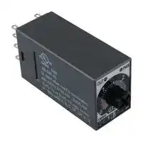


GT5Y-2SN3A100
ELECTROMECHANICAL GENERAL PURPOSE TIMER
- Manufacturer: IDEC
- Product type: Analogue Timers
- Product Range:GT5Y Series; Timer Functions:On-Delay; No. of Timing Ranges:4Ranges; Time Min:3s; Time Max:30min; Timer Output:2 Changeover Relays; Supply Voltag 30B6301
- Time Max: 30min
- Time Min: 3s
- Timer Output: 2 Changeover Relays
- Product Range: GT5Y Series
- Timer Functions: On-Delay
- Current Rating Nom: 5A
- Panel Cutout Width: 21mm
- Supply Voltage Max: 120VAC
- Panel Cutout Height: 27.5mm
- No. of Timing Ranges: 4Ranges
- Connection / Termination: Plug-In
| Delivery and price | |
|---|---|
| Units per pack | 250 |
| Price | 29.22 € |
| Current stock | 10+ |
| Lead time | 30 days |
_**Timers**_

GT5P Series

## **GT5P Series — ON Delay Timers** ~~Lo~~

**Key features of the GT5P series include:**

- **SPDT, 5A contacts**

- **8-pin, octal base**

- **• 9 time ranges**

- **Repeat error ±0.2% maximum**

- **Control settings by hand or screwdriver**

- **Power ON and timing out LED indicators**

- **Uses the same sockets and hold down clips as IDEC’s RR2P 8-pin relays**

CSA Certified UL Recognized File No. LR66809 File No. E55996

100 to 120V AC (50/60Hz) 200 to 240V AC (50/60Hz) **Rated Operating Voltage** 24V AC/DC 12V DC AC type: ±15% **Voltage Tolerance** DC type: ±10% (ripple 10% maximum) **G Resistive load** 120V AC/24V DC, 5A 240V AC, 3A **Contact Rating** 240V AC, 0.8A **Inductive load** 120V AC, 1.4A 24V DC, 1.7A 960VA AC **Allowable Contact Power** (resistive load) 120W DC re pe **Contact Form** SPDT Pe **Voltage** 250V AC, 150V DC pe **Repeat Error** ±0.2% ±10msec Pe **Voltage Error** ±0.5% ±10msec ±3% maximum (over –10 to 50°C, **Temperature Error** reference temperature 20°C) Be ee **Setting Error** ±10% maximum When turning power off after time up: 0.1 sec maximum **Reset Time** When turning power off before time up: 1 sec maximum Pe **Insulation Resistance** 100M Ω minimum 2000V AC, 1 minute (except between **Dielectric Strength** contacts of the same pole) Be ee **Vibration Resistance** 100N (approximate 10G) Operating extremes: **Shock Resistance** 100N (approximate 10G) Damage limits: 500N (approximate 50G) 100V AC type: 1.5VA (at 50Hz) **GT5P Table of Contents Power Consumption** 200V AC type: 1.6VA (at 50Hz) 24V DC type: 0.9W Specifications — G-58 ~~Po~~ **Electrical Life** 100,000 operations minimum (at rated load) Part Numbering List — G-59 ~~ee~~ **Mechanical Life** 20,000,000 operations minimum Timing Diagrams / Schematics — G-60 GT5P Accessories — G-61 ~~Po~~ **Operating Temperature** –10 to +50°C GT5P Dimensions — G-62 ~~ee~~ **Operating Humidity** 45 to 85% RH Timing Diagrams Overview — G-4

- _1.Inductive load (reference), cos_ θ _=.3 to .4 or L/R=15msec._

_2.Minimum applicable load: 5VDC/10mA (reference)._

_**www.idec.com**_

_**USA: (800) 262-IDEC or (408) 747-0550,   Canada: (888) 317-IDEC**_

_**G-58**_

_**Timers**_

GT5P Series

## **Part Numbering List** ~~|~~

|**Mode of**<br>**Operation**|**Contact**|**Output**|**Rated**<br>**Voltage**|**Time**<br>**Range**|**Complete**<br>**Part No.**|
|---|---|---|---|---|---|
|ON-Delay|SPDT|24V DC/<br>120V AC,<br>5A<br>240V AC,<br>3A|100 to<br>120V AC|1S<br>~~|~~|—<br>~~|~~|
|||||3S|GT5P-N3SA100|
|||||6S<br>~~|~~|—<br>~~|~~|
|||||10S<br>~~|~~<br>Td|GT5P-N10SA100<br>~~|~~|
|||||30S|GT5P-N30SA100|
|||||60S<br>||GT5P-N60SA100|
|||||3M<br>|<br>Td|GT5P-N3MA100|
|||||6M|GT5P-N6MA100|
|||||10M<br>Td|GT5P-N10MA100|
||||200 to<br>240V AC|1S<br>Td<br>Td|GT5P-N1SA200|
|||||3S|—|
|||||6S<br>||GT5P-N6SA200|
|||||10S<br>||GT5P-N10SA200|
|||||30S|GT5P-N30SA200|
|||||60S|GT5P-N60SA200|
|||||3M|GT5P-N3MA200|
|||||6M|GT5P-N6MA200|
|||||10M|GT5P-N10MA200|
||||24V AC/DC|1S|GT5P-N1SAD24|
|||||3S|—|
|||||6S|GT5P-N6SAD24|
|||||10S|GT5P-N10SAD24|
|||||30S|—|
|||||60S<br>|<br>Td|GT5P-N60SAD24|
|||||3M<br>|<br>Td|—|
|||||6M|GT5P-N6MAD24|
|||||10M<br>Td|GT5P-N10MAD24|
||||12V DC|1S<br>Td<br>Td|—|
|||||3S|—|
|||||6S<br>||—|
|||||10S<br>|<br>Td|GT5P-N10SD12|
|||||30S|GT5P-N30SD12|
|||||60S<br>||GT5P-N60SD12|
|||||3M<br>|<br>Td|—|
|||||6M|—|
|||||10M<br>||GT5P-N10MD12|


**==> picture [15 x 14] intentionally omitted <==**

**----- Start of picture text -----**<br>
G<br>**----- End of picture text -----**<br>


_For sockets and accessories, see page G-61._

_**www.idec.com**_

_**USA: (800) 262-IDEC or (408) 747-0550,   Canada: (888) 317-IDEC**_

_**G-59**_

_**Timers**_

GT5P Series

## **Timing Diagram/Schematic/Electrical Life Curves**

## **SPDT**

## **G**

**==> picture [308 x 386] intentionally omitted <==**

**----- Start of picture text -----**<br>
4 5<br>3 6<br>2 7<br>(-) (+)<br>Operation 1 8<br>Mode  POWER<br>Do not apply voltage to terminals 1, 3, and 4.<br>Item Terminal No. Operation<br>Set Time<br>Power (Power) 2-7<br>(NC) 5-8<br>ON-Delay ContactDelayed<br>(NO) 6-8<br>POWER<br>Indicator<br>OUT<br>Electrical Life Curves<br>100<br>70<br>50<br>30<br>20<br>24V DC Resistance Load<br>10 120V AC Resistance Load<br>7 240V AC Resistance Load<br>5 24V DC Induction Load<br>3<br>120V AC Induction Load<br>2<br>240V AC Induction Load<br>1<br>0 1 2 3 4 5<br>Load Current (A)<br>Life (x 10,000 operations)<br>**----- End of picture text -----**<br>


_**www.idec.com**_

_**G-60**_

_**USA: (800) 262-IDEC or (408) 747-0550,   Canada: (888) 317-IDEC**_

GT5P Series Accessories

## IDEC _**Timers**_ GT5P Series Accessories **Mounting Accessories** ~~Ct~~

|~~ee~~|**Part Numbers: Mounting Accessories and Sockets**<br>~~ee~~|**Part Numbers: Mounting Accessories and Sockets**<br>~~ee~~|**Part Numbers: Mounting Accessories and Sockets**<br>~~ee~~|**Part Numbers: Mounting Accessories and Sockets**<br>~~ee~~|**Applicable Hold-Down Springs**<br>**Appearance**<br>**Part No.**<br>SFA-203<br>~~ee~~|**Applicable Hold-Down Springs**<br>**Appearance**<br>**Part No.**<br>SFA-203<br>~~ee~~|
|---|---|---|---|---|---|---|
||**Style**|**Appearance**|**Use with Timers**|**Part No.**||**Part No.**|
|**DIN Rail/**<br>**Surface**<br>**Mounting**<br>**Accessories**<br>8-Pin Screw Terminal<br>(dual tier)<br>8-Pin Fingersafe Socket<br>8-Pin Screw Terminal<br>DIN Mounting Rail<br>Length 1000mm|8-Pin Screw Terminal<br>(dual tier)||GT5P|SR2P-05||SFA-203|
||8-Pin Fingersafe Socket||GT5P|SR2P-05C|||
||8-Pin Screw Terminal||GT5P|SR2P-06||SFA-202|
||DIN Mounting Rail<br>Length 1000mm||—|BNDN1000|BNDN1000||
||**Part Numbers: Mounting Accessories and Sockets**||||**Applicable Hold-Down Springs**||
|**Mounting**<br>**Accessories**<br>8-Pin Solder Terminal|8-Pin Solder Terminal|||SR2P-51||SFA-402|


**G**

## **Installation of Hold-Down Springs**

**DIN Rail Mount Socket**

**Panel Mount Socket**

Insert the springs into the outerslots with the projectionsfacing inside. Insert the springsinto the slots. Hold-down SpringSFA-402 Insert gxos Q ~al 8-pin Socket Socket SR3P-05 Hold-down Spring (sold separately) SR2P-511 SFA-203 (use two springs) Socket SR2P-06 Hold-down Spring (sold separately) - a SFA-202 (use two springs) Lan ee

_**www.idec.com**_

_**USA: (800) 262-IDEC or (408) 747-0550,   Canada: (888) 317-IDEC**_

_**G-61**_

_**Timers**_

GT5P Series Dimensions

## **Dimensions: GT5P Series**

"

## **GT5P Timer, 8-Pin with SR2P-05**

**==> picture [275 x 104] intentionally omitted <==**

**----- Start of picture text -----**<br>
(When using DIN Rail)<br>When using BAA/BAP: 102 maximum<br>98 maximum DIN Rail (BAA/BAP/BADA)<br>Hold-down�<br>spring<br>29 7.5 61 13 16.5<br>74 20<br>28.5<br>36 33 ø25 52<br>3<br>**----- End of picture text -----**<br>


## **GT5P Timer, 8-Pin with SR2P-06**

## **G**

**==> picture [235 x 104] intentionally omitted <==**

**----- Start of picture text -----**<br>
(When using DIN Rail)<br>When using BAA/BAP: 95.5 maximum<br>91.5 maximum<br>Hold-down� DIN Rail<br>Spring<br>29 7.5 61 13<br>18<br>74<br>22<br>1.7 31.7<br>36 60<br>1<br>**----- End of picture text -----**<br>


_**www.idec.com**_

_**G-62**_

_**USA: (800) 262-IDEC or (408) 747-0550,   Canada: (888) 317-IDEC**_

GT5Y Series

**G** [

## _**Timers**_ GT5Y Series NIDEC **GT5Y Series — ON Delay Timers** ~~Ld~~

## **Key features of the GT5Y series include:**

- **4PDT, 3A or DPDT, 5A contacts**

- **4 time ranges**

- **Repeat error ±0.2% maximum**

- **Control settings by hand or screwdriver**

- **Power ON and timing out LED indicators**

- **Uses the same sockets and hold-down clips as IDEC’s RY4S and RU series relays**

UL, c-uL Listed File No. E55996

**GT5Y-2 GT5Y-4** 100 to 120V AC (50/60Hz) 200 to 240V AC (50/60Hz) **Rated Operating Voltage** 24V DC 24V AC 12V DC **Contact Form** DPDT 4PDT 220V AC, 5A 220V AC, 3A Resistive Load 30V DC, 5A 30V DC, 3A **Rated Load** 220V AC, 2A 220V AC, 0.8A Inductive Load 30V DC, 2.5A 30V DC, 1.5A |}a} 1100VA AC 660VA AC Resistive Load **Allowable** 150W DC 90W DC **Contact** Inductive Load **Power** Cos Ø = 0.3 440VA AC 176VA AC 75W DC 45W DC L/r = 7msec | > **Allowable Voltage** 250V AC, 125V DC pS **Allowable Current** | 5A 3A **Temperature Error** ±3% maximum (over –10 to 50°C, reference temperature 20°C) pS **Setting Error** ±10% maximum **Reset Time** When turning power off after time up: 0.1 second maximum When turning power off before time up: 1 second maximum Se **Insulation Resistance** 100M Ω minimum ~~—~~ pe **Dielectric Strength** 2,000V AC, 1 minute (except between contacts of the same pole) pS **Vibration Resistance** 100N (approximate 10G) pe **Shock Resistance** Operating extremes: 100N (approximate 10G) Damage limits: 500N (approximate 50G) pe 100V AC type: 1.5VA (at 50Hz) **Power Consumption** 200V AC type: 1.6VA (at 50Hz) 24V DC type: 0.9W So **Electrical Life** 500,000 operations minimum 200,000 operations minimum (220V AC, 5A) (110V AC, 3A) ee **Mechanical Life** 50,000,000 operations minimum ee 50,000,000 operations minimum **Operating Temperature** –10 to +50°C pS ~~po~~ **Operating Humidity** 45 to 85% RH

**GT5Y Table of Contents** Part Number List — G-64 Timing Diagrams — G-65 GT5Y Accessories — G-66 GT5Y Dimensions — G-67

_1. Minimum applicable load: GT5Y-2: 5V DC, 20mA (reference value); GT5Y-4: 5V DC, 10mA (reference value)._

_2. Inductive load: cos_ θ _=.3, L/R=7msec._

_**www.idec.com**_

_**USA: (800) 262-IDEC or (408) 747-0550,   Canada: (888) 317-IDEC**_

_**G-63**_

_**Timers**_

GT5Y Series

## **Part Numbering List**

**G**

|**Mode of**<br>**Operation**|**Contact**|**Output**|**Rated**<br>**Voltage**|**Time Range**|**Complete**<br>**Part No.**|
|---|---|---|---|---|---|
||DPDT|220V AC/<br>30V DC, 5A|100 to 120V AC<br>||1S/10S/1M/10M<br>~~Po~~|GT5Y-2SN1A100|
|||||3S/30S/3M/30M<br>~~Po~~<br>Po|GT5Y-2SN3A100|
|||||6S/60S/6M/60M<br>Po<br>|<br>||GT5Y-2SN6A100|
||||200 to 240V AC<br>|<br>||1S/10S/1M/10M<br>|<br>||GT5Y-2SN1A200|
|||||3S/30S/3M/30M<br>|Po|GT5Y-2SN3A200|
|||||6S/60S/6M/60M<br>Po<br>|<br>||GT5Y-2SN6A200|
||||12V DC<br>|Po<br>po|1S/10S/1M/10M<br>|<br>|Po|GT5Y-2SN1D12|
|||||3S/30S/3M/30M<br>|Po|GT5Y-2SN3D12|
|||||6S/60S/6M/60M<br>Po<br>po|GT5Y-2SN6D12|
||||24V DC<br>po<br>||1S/10S/1M/10M<br>po|GT5Y-2SN1D24|
|||||3S/30S/3M/30M<br>po|GT5Y-2SN3D24|
|||||6S/60S/6M/60M<br>||GT5Y-2SN6D24|
||||24V AC<br>|Po<br>||1S/10S/1M/10M<br>|Po<br>||GT5Y-2SN1A24|
|||||3S/30S/3M/30M<br>|Po<br>||GT5Y-2SN3A24|
|||||6S/60S/6M/60M<br>Po<br>|<br>||GT5Y-2SN6A24|
||4PDT|220V AC/<br>30V DC, 3A|100 to 120V AC<br>||1S/10S/1M/10M<br>|<br>||GT5Y-4SN1A100|
|||||3S/30S/3M/30M<br>||GT5Y-4SN3A100|
|||||6S/60S/6M/60M<br>||GT5Y-4SN6A100|
||||200 to 240V AC<br>Po|1S/10S/1M/10M<br>|<br>Po|GT5Y-4SN1A200|
|||||3S/30S/3M/30M<br>Po|GT5Y-4SN3A200|
|||||6S/60S/6M/60M<br>Po|GT5Y-4SN6A200|
||||12V DC<br>Po<br>||1S/10S/1M/10M<br>Po|—|
|||||3S/30S/3M/30M|GT5Y-4SN3D12|
|||||6S/60S/6M/60M<br>|<br>||—|
||||24V DC<br>|<br>||1S/10S/1M/10M<br>|<br>||GT5Y-4SN1D24|
|||||3S/30S/3M/30M<br>|Po|GT5Y-4SN3D24|
|||||6S/60S/6M/60M<br>Po<br>|<br>||GT5Y-4SN6D24|
||||24V AC<br>||1S/10S/1M/10M<br>|<br>||GT5Y-4SN1A24|
|||||3S/30S/3M/30M<br>|Po|GT5Y-4SN3A24|
|||||6S/60S/6M/60M<br>Po|GT5Y-4SN6A24|


_1. For sockets and accessories, see page G-66._

## **Timing Ranges**

|**Code**|**Scale**<br>||**Time Range**<br>**Indication**<br>||**Time Range**<br>**Indication**<br>||**Time Range**|
|---|---|---|---|---|
|1S|0 to 10<br>|<br>|<br>|<br>|<br>||x 0.1<br>|~~|~~<br>||S<br>~~|~~<br>|0.1 second to 1 second|
|10S||x 1<br>|<br>||<br>||S<br><br>|<br>|0.2 second to 10 seconds|
|1M||x 0.1<br>||<br>||<br>||M<br>|<br>|<br>|1.2 seconds to 1 minute|
|10M||x 1<br>||<br>||<br>||M<br>|<br>|<br>|12 seconds to 10 minutes|
|3S|0 to 3<br>|<br>|<br>|<br>|<br>|<br>||x 1<br>|<br>||<br>||S<br><br>|<br>|0.1 second to 3 seconds|
|30S||x 10<br>||<br>||<br>||S<br>|<br>|<br>|0.5 second to 30 seconds|
|3M||x 1<br>||<br>||<br>||M<br>|<br>|<br>|3 seconds to 3 minutes|
|30M||x 10<br>|<br>||<br>||M<br><br>|<br>|30 seconds to 30 minutes|
|6S|0 to 6<br>|<br>|<br>|<br>|<br>||x 1<br>||<br>||<br>||S<br>|<br>|<br>|0.1 second to 6 seconds|
|60S||x 10<br>||<br>||<br>||S<br>|<br>|<br>|1 second to 60 seconds|
|6M||x 1<br>|<br>||<br>||M<br><br>|<br>|6 seconds to 6 minutes|
|60M||x 10<br>||<br>|||M<br>|<br>||1 minute to 60 minutes|


_**www.idec.com**_

_**G-64**_

_**USA: (800) 262-IDEC or (408) 747-0550,   Canada: (888) 317-IDEC**_

_**Timers**_

GT5Y Series

**G**

## **Timing Diagram/Schematics/Electrical Life Curves**

**==> picture [521 x 270] intentionally omitted <==**

**----- Start of picture text -----**<br>
GT5Y-2 GT5Y-4<br>DPDT 4PDT<br>1 4 1 2 3 4<br>5 8 5 6 7 8<br>Internal Connections<br>(bottom view)<br>9 12 9 10 11 12<br>13 (-) (+) 14 13 (-) (+) 14<br>POWER POWER<br>Item Terminal No. Operation<br>Set Time<br>Power (Power) 13-14<br>1-9, 2-10,<br>Delayed (NC) 3-11, 4-12<br>Operation Mode: Contact (NO) 5-9, 6-10,7-11, 8-12<br>ON-Delay<br>POWER<br>Indicator<br>OUT<br>For an explanation of timing modes, see page E-4.<br>**----- End of picture text -----**<br>


## **Electrical Life Curves**

**==> picture [209 x 302] intentionally omitted <==**

**----- Start of picture text -----**<br>
5000<br>AC Load<br>1000 110V AC Resistance Load GT5Y-2<br>220V AC Resistance Load GT5Y-4<br>500<br>110V AC Induction Load<br>100<br>220V AC Induction Load<br>50<br>1 2 3 4 5 Load Current (A)<br>5000<br>DC Load<br>1000 30V DC Resistance Load GT5Y-2<br>GT5Y-4<br>500<br>30V DC Induction Load<br>100V DC Resistance Load<br>100<br>100V DC Induction Load<br>50<br>1 2 3 4 5 Load Current (A)<br>Life (x 10,000 operations)<br>Life (x 10,000 operations)<br>**----- End of picture text -----**<br>


_**www.idec.com**_

_**USA: (800) 262-IDEC or (408) 747-0550,   Canada: (888) 317-IDEC**_

_**G-65**_

_**Timers**_

GT5Y Series

**Accessories** ~~Lo~~

**G** 7

## **DIN Rail Mounting Accessories** ~~Le~~

**Part Numbers: DIN Rail/Surface Mount Sockets and Hold-Down Springs DIN Rail Mount Socket** l **Applicable Hold-Down Springs Style Appearance Part No. Appearance Part No.** 14-Blade Screw Terminal SY4S-05 r SFA-202 14-Blade Screw Terminal (fingersafe) SY4S-05C set. ~~aa~~

DIN Mounting Rail Length 1000mm BNDN1000

**Panel Mounting Accessories** ~~Le~~ **Part Numbers: Panel Mount Socket and Hold-Down Springs Panel Mount Socket**

**Applicable Hold-Down Springs**

**Style Appearance Part No. Appearance Part No.** : + ~% 14-Blade Solder Terminal SY4S-51 SFA-302

**==> picture [522 x 174] intentionally omitted <==**

**----- Start of picture text -----**<br>
PCB Mounting Accessories<br>Le<br>Part Numbers: PCB Mount Sockets with Applicable Hold-Down Springs<br>PCB Mount Socket | Applicable Hold-Down Springs<br>Style Appearance Part No. | Appearance Part No.<br>14 Blade, PCB Terminal SY4S-61 SFA-302<br>- Sp %,<br>14 Blade, PCB Terminal SY4S-62 SY4S-02F1<br>**----- End of picture text -----**<br>


_**www.idec.com**_

_**G-66**_

_**USA: (800) 262-IDEC or (408) 747-0550,   Canada: (888) 317-IDEC**_

_**Timers**_

GT5Y Series

**G**

## **Dimensions**

## **GT5Y Timer, Blade with SY4S-05**

**==> picture [503 x 139] intentionally omitted <==**

**----- Start of picture text -----**<br>
28.5 when<br>When using DIN RailWhen using BAA/BAP: 87.6 maximum 30 using BAA<br>83.6 maximum 6 18<br>Terminal<br>DIN Rail (BAA) Arrangement<br>M3 Screw<br>2-ø4.2 Mounting Hole 8 7 6 5<br>(M4 screw hole) 4 3 2 1<br>Hold-� DIN�<br>21 6 52.6 6.4 down� Rail 26<br>58.6 Spring<br>18.5 4max. 4.8min. 14 13<br>25 ø3.2min. 12 11 10 9<br>18.5 (TOP VIEW)<br>26 25 5.9max.<br>0.7<br>27.5 62<br>62 45<br>3 4.2<br>3<br>**----- End of picture text -----**<br>


_**www.idec.com**_

_**USA: (800) 262-IDEC or (408) 747-0550,   Canada: (888) 317-IDEC**_

_**G-67**_

_**Timers**_

General Instructions

## **General Instructions for All Timer Series**

## **Load Current**

With inductive, capacitive, and incandescent lamp loads, inrush current more than 10 times the rated current may cause welded contacts and other undesired effects. The inrush current and steady-state current must be taken into consideration when specifying a timer.

## **Contact Protection**

Switching an inductive load generates a counter-electromotive force (back EMF) in the coil. The back EMF will cause arcing, which may shorten the contact life and cause imperfect contact. Application of a protection circuit is recommended to safeguard the contacts.

## **Temperature and Humidity**

Use the timer within the operating temperature and operating humidity ranges and prevent freezing or condensation. After the timer has been stored below its operating temperature, leave the timer at room temperature for a sufficient period of time to allow it to return to operating temperatures before use.

## **Time Setting**

The time range is calibrated at its maximum time scale; so it is desirable to use the timer at a setting as close to its maximum time scale as possible. For a more accurate time delay, adjust the control knob by measuring the operating time with a watch before application.

## **Input Contacts**

Use mechanical contact switch or relay to supply power to the timer. When driving the timer with a solid-state output device (such as a two-wire proximity switch, photoelectric switch, or solid-state relay), malfunction may be caused by leakage current from the solid-state device. Since AC types comprise a capacitive load, the SSR dielectric strength should be two or more times the power voltage when switching the timer power using an SSR **.**

Generally, it is desirable to use mechanical contacts whenever possible to apply power to a timer or its signal inputs. When using solid state devices, be cautious of inrushes and back-EMF that may exceed the ratings on such devices. Some timers are specially designed so that signal inputs switch at a lower voltage than is used to power the timer (models designated as “B" type).

## **Environment**

Avoid contact between the timer and sulfurous or ammonia gases, organic solvents (alcohol, benzine, thinner, etc.), strong alkaline substances, or strong acids. Do not use the timer in an environment where such substances are prevalent. Do not allow water to run or splash on the timer.

## **Vibration and Shock**

**G**

##

Excessive vibration or shocks can cause the output contacts to bounce, the timer should be used only within the operating extremes for vibration and shock resistance. In applications with significant vibration or shock, use of hold down springs or clips is recommended to secure a timer to its socket.

## **Timing Accuracy Formulas**

Timing accuracies are calculated from the following formulas:

**Repeat Error** = ± 1 x Maximum Measured Value – Minimum Measured Value x 100% 2 Maximum Scale Value

**Voltage Error** = ± Tv - Tr x 100% Tr

TTr:v: Average of measured values at voltage V Average of measured values at the rated voltage

## **Temperature Error**

= ± Tt - T20 x 100% T20

Tt: Average of measured values at °C T20: Average of measured values at 20°C

**Setting Error** = ± Average of Measured Values - Set Value x 100% Maximum Scale Value

_**www.idec.com**_

_**G-68**_

_**USA: (800) 262-IDEC or (408) 747-0550,   Canada: (888) 317-IDEC**_
Updated at April 29, 2026
Founded in 1945, IDEC is a globally recognized leader in industrial automation, machine safety, and control products. Renowned for pioneering innovations in Human-Machine Interface (HMI) systems, the company is dedicated to creating a safe and efficient harmony between advanced workplace technology and human operators. At the core of IDEC’s extensive portfolio is a comprehensive selection of high-performance relays designed for demanding industrial environments. This includes a broad range of electromechanical power relays, solid-state relays, contactors, and critical safety relays, supported by a wide array of specialized relay accessories to ensure reliable and efficient switching. Beyond switching components, IDEC provides complete solutions for modern control panels and automated systems. Their robust engineering extends to advanced panel displays and instrumentation, precision light sensors, and dependable AC/DC power converters. With additional offerings in industrial switches, visual signaling units, and DIN rail terminal blocks, IDEC equips engineers with the high-quality components required to build secure, next-generation automation infrastructure.
About Novapart
Novapart is a B2B electronic component broker specialising in stock shortages and cost reduction. We source hard-to-find parts and identify compliant alternatives across a catalogue of 410,000+ components from 500+ manufacturers.
Learn more →Stock Shortage Specialist
When a component is unavailable, discontinued or has an unacceptable lead time, we tap into our network of vetted European and Asian distributors to source what you need — without compromising on quality or traceability.
Request a quote →Compliant Alternatives
We identify pin-to-pin, electrically equivalent substitutes that meet the same certifications (RoHS, AEC-Q100, REACH) as your original specification — validated against datasheets, not just part numbers. Often at a lower cost.
BOM Analysis service →