
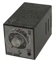


GT3F-2AF20
TIMER-COUNTER DISPLAY PANEL
- Manufacturer: IDEC
- Product type: Analogue Timers
- Product Range:GT3F Series; Timer Functions:Off-Delay; No. of Timing Ranges:8Ranges; Time Min:0.1s; Time Max:600s; Timer Output:2 Changeover Relays; Supply Voltage Max:250V 50B4190
- Time Max: 600s
- Time Min: 0.1s
- Timer Output: 2 Changeover Relays
- Product Range: GT3F Series
- Timer Functions: Off-Delay
- Current Rating Nom: 3A
- Panel Cutout Width: 45mm
- Supply Voltage Max: 250VAC
- Panel Cutout Height: 45mm
- No. of Timing Ranges: 8Ranges
- Connection / Termination: Plug-In
| Delivery and price | |
|---|---|
| Units per pack | 100 |
| Price | 80.16 € |
| Current stock | 25+ |
| Lead time | 30 days |
_**Timers**_

GT3A Series

- **GT3A Series — Analog Timers**

- ~~LT~~ **Key features of the GT3A series include: • 4 selectable operation modes on each model • External start, reset, and pause inputs • Panel mount or socket mount • Large variety of timing functions • Power and output status indicating LEDs**

- UL, c-uL Listed File No. E55996

**G**

|||File No. E55996<br>C~~E~~|~~E~~|||
|---|---|---|---|---|---|
|||**GT3A-1**|**GT3A-2**|**GT3A-3**|**GT3A-4,-5,-6**|
|**Specifications**|**Operation**|Multi-mode|||Multi-mode with inputs (11 pins)|
||**Time Range**|0.05s to 180 hours||||
||**Rated Voltage**|100 to 240V AC, 50/60Hz<br>12V DC<br>24V AC, 50/60Hz / 24V DC||||
||**Contact Ratings**|125V AC/250V AC, 3A;<br>30V DC, 1A (resistive load)||125V AC/250V AC, 5A;<br>30V DC, 5A (resistive load)||
||**Minimum Applicable**<br>**Load**|5V, 10mA (reference value)||||
||**Voltage Tolerance**|AF20 (100V AC): 85 to 264V AC<br>AD24: 20.4 to 26.4V AC/21.6 to 26.4V DC<br>D12: 10.8 to 13.2V DC||||
||**Error**|±0.2%,±10 msec (repeat, voltage, temperature)||||
||**Setting Error**|±10% maximum||||
||**Reset Time**|60msec maximum||||
||**Insulation Resistance**|100MΩminimum||||
||**Dielectric Strength**|Between power and output terminals: 2,000V AC, 1 minute<br>Between contacts of different poles: 2,000V AC, 1 minute<br>Between contacts of the same pole: 750V AC, 1 minute||||
||**Power Consumption**<br>(approximate)|Delayed SPDT|Delayed SPDT +<br>instantaneous SPDT|Delayed DPDT|Delayed DPDT|
|||10.8VA<br>(200V AC, 60Hz)|13.5VA<br>(200V AC, 60Hz)|14.4VA<br>(200V AC, 60Hz)|4.7VA (100V AC, 60Hz),<br>14.4VA (200V AC, 60Hz)|
|||–|12VDC/1W|12VDC/1.1W|12VDC/0.8W|
||||24VDC/0.7W<br>24VAC/1.2VA|24VDC/0.6W<br>24VAC/1.3VA|24VDC/0.6W<br>24VAC/1.3VA|
||**Mechanical Life**|10,000,000 operations minimum||5,000,000 operations minimum||
||**Electrical LIfe**|50,000 operations minimum (rated load)||100,000 operations minimum (rated load)||
||**Weight**(approximate)|63g|73g|79g|80g|
||**Vibration Resistance**|100m/sec2(approximate 10G)||||
||**Shock Resistance**|Operating extremes: 100m/sec2(approximate 10G)<br>Damage limits: 500m/sec2(approximate 50G)<br>**GT3A Table of Contents**||||
||**Operating Temperature**|–10 to +50°C<br>Specifications — G-14||||
||**Operating Humidity**|45 to 85% RH<br>Part Number List — G-15<br>Timing Diagrams/Schematics — G-16||||
||**Storage Temperature**|–30 to +80°C<br>Timing Diagrams/Schematics — G-16<br>Instructions: Setting Timer — G-22||||
||**Housing Color**|Gray<br>Instructions: Setting Timer — G-22<br>~~GT3 Accessories —~~||||


_**www.idec.com**_

_**USA: (800) 262-IDEC or (408) 747-0550,   Canada: (888) 317-IDEC**_

_**G-14**_

_**Timers**_

GT3A Series

**G**

## **Part Number List**

## **Part Numbers: GT3A-1, -2, -3**

|**Mode Of**<br>**Operation**|**Rated Voltage Code**|**Time**<br>**Range**|**Output**|**Contact**|**Complete Part No.**|**Complete Part No.**|
|---|---|---|---|---|---|---|
||||||**8-Pin**|**11-Pin**|
|A: ON-delay 1<br>B: Interval 1<br>C: Cycle 1<br>D: Cycle 3|AF20: 100 to 240V AC (50/60Hz)|0.05s.<br>to<br>180<br>hours|250V AC, 3A,<br>30V DC, 1A<br>(resistive load)|Delayed SPDT|GT3A-1AF20|GT3A-1EAF20|
||AF20: 100 to 240V AC (50/60Hz)<br>D12: 12V DC<br>AD24: 24V AC (50/60Hz)/24V DC|||Delayed SPDT +<br>Instantaneous<br>SPDT|GT3A-2AF20|GT3A-2EAF20|
||||||GT3A-2D12|GT3A-2ED12|
||||||GT3A-2AD24|GT3A-2EAD24|
||||240V AC, 5A,<br>24V DC, 5A<br>(resistive load)|Delayed DPDT|GT3A-3AF20|GT3A-3EAF20|
||||||GT3A-3D12|GT3A-3ED12|
||||||GT3A-3AD24|GT3A-3EAD24|


_1. For wiring schematics and timing diagrams for GT3A-1, -2, -3, see pages G-16, G-17, or G-18 respectively._

_2. For more details about time ranges, see instructions on page G-22._

_3. For socket and accessory part numbers, see page G-48._

## **Part Numbers: GT3A-4, -5, -6**

|**Mode of**<br>**Operation**|**Rated Voltage Code**|**Time**<br>**Range**|**Output**|**Contact**|**Input**|**Complete Part No.**|**Complete Part No.**|
|---|---|---|---|---|---|---|---|
|||||||**A (11-pin)**|**B (11-pin)**|
|A: ON-Delay 2<br>B: Cycle 2<br>C: Signal ON/OFF-Delay 1<br>D: Signal OFF-Delay 1|AF20: 100 to 240V AC (50/60Hz)<br>D12: 12V DC<br>AD24: 24V AC (50/60Hz)/24V DC|0.05<br>seconds<br>to<br>180 hours|250V AC, 5A,<br>24V DC, 5A<br>(resistive load)|Delayed<br>DPDT|Start<br>Reset<br>Gate|GT3A-4AF20|GT3A-4EAF20|
|||||||GT3A-4D12|GT3A-4ED12|
|||||||GT3A-4AD24|GT3A-4EAD24|
|A: Interval 2<br>B: One-Shot Cycle<br>C: Signal ON/OFF-Delay 2<br>D: Signal OFF-Delay 2|AF20: 100 to 240V AC (50/60Hz)<br>AD24: 24V AC (50/60Hz)/24V DC|||||GT3A-5AF20|GT3A-5EAF20|
|||||||GT3A-5AD24|GT3A-5EAD24|
|A: One-Shot<br>B: One-Shot ON-Delay<br>C: One-Shot 2<br>D: Signal ON/OFF-Delay 3||||||GT3A-6AF20|GT3A-6EAF20|
|||||||GT3A-6AD24|GT3A-6EAD24|


_4. For wiring schematics and timing diagrams GT3A-4,-5,-6, see pages G-19, G-20, and G-21 respectively._

_5. For more details about time ranges, see instructions on page G-22._

_6. A (11-pin) and B (11-pin) differ in the way inputs are wired._

_7. For socket and accessory part numbers, see page G-48._

_8. For the timing diagrams overview, see page G-4._

_**www.idec.com**_

_**USA: (800) 262-IDEC or (408) 747-0550,   Canada: (888) 317-IDEC**_

_**G-15**_

_**Timers**_

GT3A Series

## **Timing Diagrams/Schematics**

## **GT3A- 1 Timing Diagrams**

## **Delayed SPDT**

**G**

**==> picture [282 x 561] intentionally omitted <==**

**----- Start of picture text -----**<br>
8-Pin 4 5 11-Pin 5 6 7<br>4 8<br>3 6<br>3 9<br>2 7<br>(-) (+) 2 10<br>(-) (+)<br>Operation 1 8 1 11<br>Mode Selection POWER POWER<br>Item Terminal No. Operation<br>ON-Delay 1 Power (Power) 2-7 (8p)2-10 (11p) Set Time<br>MODE<br>5-8 (8p)<br>A Delayed (NC) 8-11 (11p)<br>Contact 6-8 (8p)<br>(NO) 9-11 (11p)<br>POWER<br>Indicator<br>OUT<br>Item Terminal No. Operation<br>Interval 1 Power (Power) 2-7 (8p)2-10 (11p) Set Time<br>MODE 5-8 (8p)<br>B Delayed (NC) 8-11 (11p)<br>Contact 6-8 (8p)<br>(NO) 9-11 (11p)<br>POWER<br>Indicator<br>OUT<br>Item Terminal No. Operation<br>Cycle 1 Set Time<br>(OFF first) Power (Power) 2-7 (8p)2-10 (11p)<br>MODE Delayed (NC) 5-8 (8p)8-11 (11p)<br>C Contact 6-8 (8p)<br>(NO) 9-11 (11p)<br>POWER<br>Indicator<br>OUT<br>Item Terminal No. Operation<br>Cycle 3 Set Time<br>(ON first) Power (Power) 2-7 (8p)2-10 (11p)<br>MODE 5-8 (8p)<br>Delayed (NC) 8-11 (11p)<br>D Contact 6-8 (8p)<br>(NO) 9-11 (11p)<br>POWER<br>Indicator<br>OUT<br>**----- End of picture text -----**<br>


_**www.idec.com**_

_**G-16**_

_**USA: (800) 262-IDEC or (408) 747-0550,   Canada: (888) 317-IDEC**_

_**Timers**_

GT3A Series

**G**

## **GT3A- 2 Timing Diagrams**

## **Delayed SPDT + Instantaneous SPDT**

**==> picture [308 x 631] intentionally omitted <==**

**----- Start of picture text -----**<br>
8-Pin 4 5 11-Pin 5 6 7<br>4 8<br>3 6<br>3 9<br>2 7<br>(-) (+) 2 10<br>Operation (-) (+)<br>Mode Selection 1 8 1 11<br>POWER POWER<br>Item Terminal No. Operation<br>Set Time<br>Power (Power) 2-7 (8p)2-10 (11p)<br>5-8 (8p)<br>ON-Delay 1 (NC)<br>Delayed 8-11 (11p)<br>Contact<br>MODE 6-8 (8p)<br>(NO) 9-11 (11p)<br>A<br>Instan- (NC) 1-4<br>taneous<br>Contact (NO) 1-3<br>POWER<br>Indicator<br>OUT<br>Item Terminal No. Operation<br>Set Time<br>Power (Power) 2-7 (8p)2-10 (11p)<br>Interval 1 Delayed (NC) 5-8 (8p)8-11 (11p)<br>MODE Contact (NO) 6-8 (8p)9-11 (11p)<br>B<br>Instan- (NC) 1-4<br>taneous<br>Contact (NO) 1-3<br>POWER<br>Indicator<br>OUT<br>Item Terminal No. Operation<br>Set Time<br>Power (Power) 2-7 (8p)2-10 (11p)<br>Cycle 1<br>5-8 (8p)<br>(OFF first) Delayed (NC) 8-11 (11p)<br>Contact 6-8 (8p)<br>(NO) 9-11 (11p)<br>MODE<br>C Instan- (NC) 1-4<br>taneous<br>Contact (NO) 1-3<br>POWER<br>Indicator<br>OUT<br>Item Terminal No. Operation<br>Set Time<br>Power (Power) 2-7 (8p)2-10 (11p)<br>Cycle 3<br>5-8 (8p)<br>(ON first) (NC)<br>Delayed 8-11 (11p)<br>Contact 6-8 (8p)<br>(NO) 9-11 (11p)<br>MODE<br>D Instan- (NC) 1-4<br>taneous<br>Contact (NO) 1-3<br>POWER<br>Indicator<br>OUT<br>**----- End of picture text -----**<br>


_**www.idec.com**_

_**USA: (800) 262-IDEC or (408) 747-0550,   Canada: (888) 317-IDEC**_

_**G-17**_

_**Timers**_

GT3A Series

## **GT3A-3 Timing Diagrams**

## **Delayed DPDT**

**G**

**==> picture [308 x 606] intentionally omitted <==**

**----- Start of picture text -----**<br>
8-Pin 4 5 11-Pin 5 6 7<br>4 8<br>3 6<br>3 9<br>2 7<br>(-) (+) 2 10<br>Operation (-) (+)<br>Mode Selection 1 8 1 11<br>POWER POWER<br>Item Terminal No. Operation<br>Set Time<br>ON-Delay 1 Power (Power) 2-7 (8p)2-10 (11p)<br>MODE 1-4, 5-8 (8p)<br>Delayed(NC)1-4, 8 -11(11p)<br>A Contact 1-3, 6-8 (8p)<br>(NO)1-3, 9-11(11p)<br>POWER<br>Indicator<br>OUT<br>Item Terminal No. Operation<br>Set Time<br>Interval 1 Power (Power) 2-7 (8p)2-10 (11p)<br>MODE Delayed(NC)1-4, 8 -11(11p)1-4, 5-8 (8p)<br>B Contact 1-3, 6-8 (8p)<br>(NO)1-3, 9-11(11p)<br>POWER<br>Indicator<br>OUT<br>Item Terminal No. Operation<br>Set Time<br>Cycle 1 (OFF first) Power (Power) 2-7 (8p)2-10 (11p)<br>1-4, 5-8 (8p)<br>MODE Delayed (NC)1-4, 8 -11(11p)<br>Contact<br>C (NO)1-3, 6-8 (8p)1-3, 9-11(11p)<br>POWER<br>Indicator<br>OUT<br>Item Terminal No. Operation<br>Cycle 3 (ON first) Power (Power) 2-7 (8p)2-10 (11p) Set Time<br>1-4, 5-8 (8p)<br>MODE (NC)1-4, 8 -11(11p)<br>Delayed<br>D Contact (NO)1-3, 6-8 (8p)1-3, 9-11(11p)<br>POWER<br>Indicator<br>OUT<br>**----- End of picture text -----**<br>


_**www.idec.com**_

_**USA: (800) 262-IDEC or (408) 747-0550,   Canada: (888) 317-IDEC**_

_**G-18**_

_**Timers**_

GT3A Series

**G**

## **GT3A-4 Timing Diagrams**

**==> picture [526 x 667] intentionally omitted <==**

**----- Start of picture text -----**<br>
Delayed DPDT<br>(A Type)(Contact Input) (Transistor Input) (B Type) Note: T = Set time<br>Ta = Shorter<br>than set time<br>Start Reset T = T' + T"<br>6 6 6<br>5 7 5 7 5 7<br>Reset StartGate<br>4 8 4 8 4 8<br>ResetStartGate<br>3 9 3 9 3 9<br>2 10 2 10 2 10<br>Operation (-) 1 11 (+) (-) 1 11 (+) (-) 1 11 (+)<br>Mode Selection<br>POWER POWER POWER<br>Item Terminal No. Operation<br>Power 2-10 (POWER)<br>Start 2-6 (A)5-7 (B) [ON or L]<br>ON-Delay 2 Reset 2-7 (A)6-7 (B) [ON or L]<br>MODE Gate 2-5 (A) ON or L<br>1-4<br>A Delayed 8-11 [(NC)]<br>Contact 1-3<br>9-11 [(NO)]<br>POWER<br>Indicator<br>OUT<br>Set Time T Ta T' T"<br>Note: While the gate input is on<br>during time-delay operation, the<br>POWER indicator flash rate slows down.<br>Item Terminal No. Operation<br>Power 2-10 (POWER)<br>Start 2-6 (A)5-7 (B) [ON or L]<br>Cycle 2 Reset 2-7 (A)6-7 (B) [ON or L]<br>MODE<br>Gate 2-5 (A) ON or L<br>B<br>1-4<br>Delayed 8-11 [(NC)]<br>Contact 1-3<br>9-11 [(NO)]<br>POWER<br>Indicator<br>OUT<br>Set Time T T T T T T T Ta T T T T’ T’’ T T T T T<br>Item Terminal No. Operation<br>Power 2-10 (POWER)<br>Start 2-6 (A)5-7 (B) [ON or L]<br>Signal ON/OFF-Delay 1 Reset 2-7 (A)6-7 (B) [ON or L]<br>MODE<br>Gate 2-5 (A) ON or L<br>C 1-4<br>Delayed 8-11 [(NC)]<br>Contact 1-3<br>9-11 [(NO)]<br>POWER<br>Indicator<br>OUT<br>Set Time T T Ta T Ta T T T T’’ Ta<br>Item Terminal No. Operation<br>Power 2-10 (POWER)<br>Start 2-6 (A)5-7 (B) [ON or L]<br>Signal OFF-Delay 1 Reset 2-7 (A)6-7 (B) [ON or L]<br>MODE<br>Gate 2-5 (A) ON or L<br>D 1-4<br>Delayed 8-11 [(NC)]<br>Contact 1-3<br>9-11 [(NO)]<br>POWER<br>Indicator<br>OUT<br>Set Time T Ta Ta T T’ Ta<br>Input<br>Input<br>Input<br>Input<br>**----- End of picture text -----**<br>


_**www.idec.com**_

_**USA: (800) 262-IDEC or (408) 747-0550,   Canada: (888) 317-IDEC**_

_**G-19**_

_**Timers**_

GT3A Series

## **GT3A- 5 Timing Diagrams**

**==> picture [553 x 679] intentionally omitted <==**

**----- Start of picture text -----**<br>
.<br>Delayed DPDT<br>(A Type)<br>(Contact Input) (Transistor Input) (B Type)<br>Note: T = Set time<br>Start Reset Ta = Shorter<br>5 6 7 5 6 7 5 6 7 than set time<br>Reset StartGate T = T’ + T”<br>4 8 4 8 4 8<br>ResetStartGate<br>3 9 3 9 3 9<br>Operation 2 10 2 10 2 10<br>Mode Selection (-) 1 11 (+) (-) 1 11 (+) (-) 1 11 (+)<br>POWER POWER POWER<br>Item Terminal No. Operation<br>Power 2-10 (POWER)<br>Start 2-6 (A)5-7 (B) [ON or L]<br>Interval 2 Reset 2-7 (A)6-7 (B) [ON or L]<br>MODE<br>Gate 2-5 (A) ON or L<br>A 1-4<br>Delayed 8-11 [(NC)]<br>Contact 1-3<br>9-11 [(NO)]<br>POWER<br>Indicator<br>OUT<br>Set Time T Ta T' T"<br>G Item Terminal No. Operation<br>Power 2-10 (POWER)<br>Start 2-6 (A)5-7 (B) [ON or L]<br>One-Shot Cycle Reset 2-7 (A)6-7 (B) [ON or L]<br>MODE<br>Gate 2-5 (A) ON or L<br>B 1-4<br>Delayed 8-11 [(NC)]<br>Contact 1-3<br>9-11 [(NO)]<br>POWER<br>Indicator<br>OUT<br>Set Time T T T Ta T' T" T<br>Item Terminal No. Operation<br>Power 2-10 (POWER)<br>Start 2-6 (A)5-7 (B) [ON or L]<br>Signal ON/OFF-Delay 2 Reset 2-7 (A)6-7 (B) [ON or L]<br>MODE<br>Gate 2-5 (A) ON or L<br>C 1-4<br>Delayed 8-11 [(NC)]<br>Contact 1-3<br>9-11 [(NO)]<br>POWER<br>Indicator<br>OUT<br>Set Time T T Ta T Ta Ta T T' T" Ta<br>Item Terminal No. Operation<br>Power 2-10 (POWER)<br>Start 2-6 (A)5-7 (B) [ON or L]<br>Signal OFF-Delay 2<br>Reset 2-7 (A)6-7 (B) [ON or L]<br>MODE<br>Gate 2-5 (A) ON or L<br>D<br>1-4<br>Delayed 8-11 [(NC)]<br>Contact 1-3<br>9-11 [(NO)]<br>POWER<br>Indicator<br>OUT<br>Set Time T Ta Ta T T' T"<br>Input<br>Input<br>Timers<br>Input<br>Input<br>**----- End of picture text -----**<br>


_**www.idec.com**_

_**USA: (800) 262-IDEC or (408) 747-0550,   Canada: (888) 317-IDEC**_

_**G-20**_

_**Timers**_

GT3A Series

## **GT3A- 6 Timing Diagrams**

**==> picture [521 x 666] intentionally omitted <==**

**----- Start of picture text -----**<br>
Delayed DPDT<br>(A Type)<br>(Contact Input) (Transistor Input) (B Type)<br>Note: T = Set time<br>Start Reset Ta = Shorter<br>5 6 7 5 6 7 5 6 7 than set time<br>Reset StartGate T = T' + T"<br>4 8 4 8 4 8<br>ResetStartGate<br>3 9 3 9 3 9<br>2 10 2 10 2 10<br>Operation (-) 1 11 (+) (-) 1 11 (+) (-) 1 11 (+)<br>Mode Selection<br>POWER POWER POWER<br>Item Terminal No. Operation<br>Power 2-10 (POWER)<br>Start 2-6 (A)5-7 (B) [ON or L]<br>One-Shot 1<br>Reset 2-7 (A)6-7 (B) [ON or L]<br>MODE<br>Gate 2-5 (A) ON or L<br>A 1-4<br>Delayed 8-11 [(NC)]<br>Contact 1-3<br>9-11 [(NO)]<br>POWER<br>Indicator<br>OUT<br>Set Time Ta Ta T Ta T' T"<br>Item Terminal No. Operation<br>Power 2-10 (POWER)<br>Start 2-6 (A)5-7 (B) [ON or L]<br>One-Shot ON-Delay Reset 2-7 (A)6-7 (B) [ON or L]<br>MODE<br>Gate 2-5 (A) ON or L<br>B 1-4<br>Delayed 8-11 [(NC)]<br>Contact 1-3<br>9-11 [(NO)]<br>POWER<br>Indicator<br>OUT<br>Set Time T T Ta T T T' T"<br>Item Terminal No. Operation<br>Power 2-10 (POWER)<br>Start 2-6 (A)5-7 (B) [ON or L]<br>One Shot 2<br>Reset 2-7 (A)6-7 (B) [ON or L]<br>MODE<br>Gate 2-5 (A) ON or L<br>C<br>1-4<br>Delayed 8-11 [(NC)]<br>Contact 1-3<br>9-11 [(NO)]<br>POWER<br>Indicator<br>OUT<br>Set Time T Ta T T' T"<br>Item Terminal No. Operation<br>Power 2-10 (POWER)<br>Signal  Start 2-6 (A)5-7 (B) [ON or L]<br>ON/OFF-Delay 3 Reset 2-7 (A)6-7 (B) [ON or L]<br>MODE Gate 2-5 (A) ON or L<br>D 1-4<br>Delayed 8-11 [(NC)]<br>Contact 1-3<br>9-11 [(NO)]<br>POWER<br>Indicator<br>OUT<br>Set Time T T Ta T' T"’ Ta Ta T<br>Input<br>Input<br>Input<br>Input<br>**----- End of picture text -----**<br>


**G**

_**www.idec.com**_

_**USA: (800) 262-IDEC or (408) 747-0550,   Canada: (888) 317-IDEC**_

_**G-21**_

_**Timers**_

GT3A Series

## **Instructions: Setting GT3A Series Timers**

||**Desired Mode of Operation**<br>——_———|**Desired Mode of Operation**<br>——_———|**Selection**<br>——_———|**Selection**<br>——_———|**Remarks**<br>——_———|
|---|---|---|---|---|---|
||**For Timers**<br>——_———|**Mode of Operation**<br>——_———|➀**Operation Mode Selector**<br>——_———||The desired operation mode<br>can be selected from the A, B,<br>C, and D modes using the Oper-<br>ation Mode Selector. Change<br>the operation mode from A to<br>B, C, and D in turn by turning<br>the operation mode selector<br>clockwise using a flat screw-<br>driver which is a maximum of<br>0.156” (4mm) wide. The<br>selected mode is displayed<br>in the window.<br>——_———|
||GT3A-1<br>GT3A-2<br>GT3A-3<br>——_———<br>—=—_|ON-delay 1<br>——_———|A<br>——_———|||
|||Interval 1<br>——_———|B<br>——_———|||
|||Cycle 1<br>——_———|C<br>——_———|||
|||Cycle 3<br>——_———<br>~~>~~<br>—=—_|D<br>——_———<br>~~>~~<br>—=—_==|||
||GT3A-4<br>——_———<br>—=—_<br>—=—_|ON-delay 2<br>——_———<br>~~>~~<br>—=—_|A<br>——_———<br>~~>~~<br>—=—_==|||
|||Cycle 2<br>——_———<br>~~>~~<br>—=—_|B<br>——_———<br>~~>~~<br>—=—_==|||
|||Signal ON/OFF-delay 1<br>—=—_|C<br>—=—_==|||
|||Signal OFF-delay 1<br>—=—_<br>—=—_|D<br>—=—_==<br>—=—_==|||
||GT3A-5<br>—=—_<br>—=—_|Interval 2<br>—=—_<br>—=—_|A<br>—=—_==<br>—=—_==|||
|||One-shot cycle<br>—=—_<br>—=—_|B<br>—=—_ ==<br>—=—_==|||
|||Signal ON/OFF-delay 2<br>—=—_|C<br>—=—_==|||
|||Signal OFF-delay 2<br>—=—_|D<br>—=—_==|||
||GT3A-6<br>—=—_<br>SS|One-shot 1<br>—=—_<br>SS|A<br>—=—_==<br>SS|||
|||One-shot ON-delay<br>—=—_<br>SS|B<br>—=—_ ==<br>SS|||
|||One-shot 2<br>SS|C<br>SS|||
|||Signal ON/OFF-delay 3<br>SS|D<br>SS|||
|**Step 2.**|**Desired Time Range**||**Selection**||**Remarks**|
||**Time Ranges**<br>———||➁**Dial Selector**<br>ee|➂**Time Range Selector**<br>ee|The desired time range is<br>selected by setting both<br>➁Dial Selector and<br>➂Time Range Selector.|
||0.05 seconds to 1 second<br>———||0-1<br>ee|1S<br>ee<br>ee||
||0.05 seconds to 3 seconds<br>———||0-3<br>ee|||
||0.05 seconds to 6 seconds<br>———||0-6<br>ee|||
||0.15 seconds to 18 seconds<br>———<br>———||0-18<br>ee<br>ee|||
||0.1 seconds to 10 seconds<br>———<br>———||0-1<br>ee<br>ee|10S<br>ee<br>ee<br>ee||
||0.3 seconds to 30 seconds<br>———<br>———||0-3<br>ee<br>ee|||
||0.6 seconds to 60 seconds<br>———||0-6<br>ee|||
||1.8 seconds to 180 seconds<br>———<br>———||0-18<br>ee<br>ee|||
||6 seconds to 10 minutes<br>———<br>———||0-1<br>ee<br>ee|10M<br>ee<br>ee||
||18 seconds to 30 minutes<br>———<br>———||0-3<br>ee<br>ee|||
||36 seconds to 60 minutes<br>———||0-6<br>ee|||
||108 seconds to 180 minutes<br>———||0-18<br>ee|||
||6 minutes to 10 hours<br>———<br>——||0-1<br>ee<br>——|10H<br>ee<br>——||
||18 minutes to 30 hours<br>———<br>——||0-3<br>ee<br>——|||
||36 minutes to 60 hours<br>——||0-6<br>——|||
||108 minutes to 180 hours<br>——||0-18<br>——|||
|**Step 3.**|**Selection**|||||


**Set the precise period of time desired by using the** ➃ **Setting Knob.**

_**www.idec.com**_

_**USA: (800) 262-IDEC or (408) 747-0550,   Canada: (888) 317-IDEC**_

_**G-22**_

GT3D Series

## _**Timers**_ GT3D Series NIDEC **GT3D Series — Digital Timers** ~~Ld~~

**Key features of the GT3D series include:**

- **Precise time setting using digital thumbwheel switches**

- **Elapsed or time remaining LED display**

- **6 time ranges, 16 timing functions**

**• Time delays up to 99.9 hours** UL Recognized CSA Certified Cert. No. File No.E55996 File No.LR58183 BL9801133323911 (LVD) LR96764 E9971113332388 (EMC) LR83814 ee **GT3D-2 GT3D-3 GT3D-4 GT3D-8** po **Operation System** Solid state CMOS circuitry Multi-mode. **Operation** Multi-mode one-shot output ee po **Time Range** 0.01s to 99.9 hours po **Rated Voltage** 100 to 240V AC (50/60Hz), 24V AC (50/60Hz)/24V DC 125V AC/250V AC, 3A; 125V AC/250V AC, 5A; **Contact Ratings** 30V DC/1A (resistive load) 30V DC/5A (resistive load) ee **Contact Form** eee instantaneous SPDTDelayed SPDT + Delayed DPDT Delayed DPDT Delayed DPDT ee **Minimum Applicable Load** 5V, 10mA (reference value) **Voltage Tolerance** AF20 (100–240V AC): 85 to 264V ACAD24 (AC): 20.4 to 26.4V AC **G** AD24 (DC): 21.6 to 26.4V DC [| **Error** ±0.3% ±50ms (voltage, repeat, and temperature) pepo **Setting Error** ±0.5% ±50ms **Reset Time** 60ms maximum pepo **Insulation Resistance** 100M Ω minimum Between power and output terminals: 2,000V AC, 1 minute **Dielectric Strength** Between contacts of different poles: 2,000V AC, 1 minute Between contacts of the same pole: 750V AC, 1 minute **Power AF20** 11.8VA 11.6VA 3.7VA (100V AC, 60Hz) 11.6VA (200V AC, 60Hz) **Consumption** (approximate) **AD24 AC/DC** 1VA/0.8W 2.1VA/0.9W 2.1VA /0.9W SSa **Mechanical Life** 10,000,000 operations minimum 5,000,000 operations minimum ee **Electrical Life** (at rated load) 50,000 operations minieee mum 100,000 operations minimum ee 250V AC, 3A, 30V DC, 1A eee 240V AC/, 24V DC, 5A **Outputs Relay** (resistive load) (resistive load) ee **Vibration Resistance** ee ee 100N (approximate 10G) **GT3D Table of Contents Shock Resistance** Operating extremes: 100N (approximate 10G) Specifications — G-23 Damage limits: 500N (approximate 50G) BS Part Number List — G-24 po **Operating Temperature** –10 to +50°C Timing Diagrams/ **Storage Temperature** –30 to +80°C Schematics — G-25 pepo **Operating Humidity** 45 to 85% RH Instructions: Setting Timer — G-33 PT **Weight** (approximate) 70g 75g 76g GT3 Accessories — G-48 ~~po~~ **Housing Color** Gray GT3 Instructions: Wiring Inputs — G-50 GT3 Dimensions — G-52 Timing Diagrams Overview — G-4

_**www.idec.com**_

_**USA: (800) 262-IDEC or (408) 747-0550,   Canada: (888) 317-IDEC**_

_**G-23**_

_**Timers**_

GT3D Series

## **Part Number List**

## **Part Numbers: GT3D-1/GT3D-2/GT3D-3**

**G**

##

|**Mode of Operation**|**Time**<br>**Range**|**Output**|**Contact**|**Rated Voltage Code**|**Complete Part No.**|**Complete Part No.**|
|---|---|---|---|---|---|---|
||||||**8-Pin**|**11-Pin**|
|1-A: ON-delay 1<br>1-B: Interval 1 frst<br>1-C: Cycle 1 (OFF frst)<br>1-D: Cycle 3 (ON frst)|0.01s to<br>99.9<br>hours|250V AC, 3A,<br>30V DC, 1A<br>(resistive load)|Delayed SPDT<br>+ instantaneous SPDT|100 to 240V AC (50/60Hz)|GT3D-2AF20|GT3D-2EAF20|
|||||24V AC/DC|GT3D-2AD24|—|
|||240V AC/,<br>24V DC, 5A<br>(resistive load)|Delayed DPDT|100 to 240V AC (50/60Hz)|GT3D-3AF20|GT3D-3EAF20|
|||||24V AC/DC|GT3D-3AD24|—|
|**Part Numbers: GT3D-4**|||||||
|**Mode of Operation**|**Time**<br>**Range**|**Output**|**Contact**|**Rated Voltage Code**|**Complete Part No.**||
||||||**A (11-pin)**|**B (11-pin)**|
|1-A: ON-delay 1<br>1-B: Interval 1 frst<br>1-C: Cycle 1 (OFF frst)<br>1-D: Cycle 3 (ON frst)<br>2-A: ON-delay 2<br>2-B: Cycle 2<br>2-C: Signal ON/OFF-delay 1<br>2-D: Signal OFF-delay 1<br>2-E: Interval 2<br>2-F: One-shot cycle<br>3-A: Signal ON/OFF-delay 2<br>3-B: Signal OFF-delay 2<br>3-C: One-shot 1<br>3-D: One-shot ON-delay<br>3-E: One-shot 2<br>3-F: Signal ON/OFF-delay 3|0.01s to<br>99.9<br>hours|240V AC/24V DC,<br>5A<br>(resistive load)|Delayed DPDT|100 to 240V AC (50/60Hz)|GT3D-4AF20|GT3D-4EAF20|
|||||24V AC/DC|GT3D-4AD24|—|


## **Part Numbers: GT3D-8**

|**Mode of**<br>**Operation**|**Time**<br>**Range**|**Output**|**Contact**|**Rated Voltage Code**|**Complete Part No. (11-pin)**|
|---|---|---|---|---|---|
|1: ON-delay one-shot 1<br>2: Cycle one-shot<br>3: ON-delay one-shot 2|0.01s to<br>99.9<br>hours|240V AC/24V DC,<br>5A<br>(resistive load)|Delayed DPDT|100 to 240V AC (50/60Hz)|GT3D-8AF20|
|||||24V AC/DC|GT3D-8AD24|


_1. For wiring schematics and timing diagrams GT3D, see pages G-25 to G-32._

_2. For more details about time ranges, see instructions on page G-33._

_3. A (11-pin) and B (11-pin) differ in the way inputs are wired._

_4. For socket and accessory part numbers, see page G-48._

_5. For timing diagrams overview, see page G-4._

_**www.idec.com**_

_**USA: (800) 262-IDEC or (408) 747-0550,   Canada: (888) 317-IDEC**_

_**G-24**_

_**Timers**_

GT3D Series

**G**

## **GT3D-2 Timing Diagrams**

**==> picture [307 x 660] intentionally omitted <==**

**----- Start of picture text -----**<br>
Contact Delayed SPDT + Instantaneous SPDT<br>8-Pin 4 5 11-Pin 5 6 7<br>4 8<br>3 6<br>3 9<br>2 7<br>(-) (+) 2 10<br>(-) (+)<br>1 8 1 11<br>POWER POWER<br>Item Terminal No. Operation<br>Set Time<br>Power (Power) 2-7 (8p)2-10 (11p)<br>1-4, 5-8 (8p)<br>ON-Delay 1 Delayed (NC) 1-4, 8-11 (11p)<br>Contact (NO) 1-3, 6-8 (8p)<br>Time Remaining 1-3, 9-11 (11p)<br>1 — A Instan- (NC) 1-4<br>taneous<br>Time Elapsed Contact (NO) 1-3<br>1 — A Indicator OUT<br>Digital DOWN<br>Time<br>Display UP<br>Item Terminal No. Operation<br>Set Time<br>Power (Power) 2-7 (8p)2-10 (11p)<br>1-4, 5-8 (8p)<br>Interval 1 Delayed (NC) 1-4, 8-11 (11p)<br>Contact (NO) 1-3, 6-8 (8p)<br>Time Remaining 1-3, 9-11 (11p)<br>1 — B Instan- (NC) 1-4<br>taneous<br>Time Elapsed Contact (NO) 1-3<br>1 — B Indicator OUT<br>Digital DOWN<br>Time<br>Display UP<br>Item Terminal No. Operation<br>Set Time<br>Power (Power) 2-7 (8p)2-10 (11p)<br>1-4, 5-8 (8p)<br>Cycle 1  (OFF first) Delayed (NC) 1-4, 8-11 (11p)<br>Contact (NO) 1-3, 6-8 (8p)<br>Time Remaining 1-3, 9-11 (11p)<br>1 — C Instan- (NC) 1-4<br>taneous<br>Time Elapsed Contact (NO) 1-3<br>1 — C Indicator OUT<br>Digital DOWN<br>Time<br>Display UP<br>Item Terminal No. Operation<br>Set Time<br>Power (Power) 2-7 (8p)2-10 (11p)<br>1-4, 5-8 (8p)<br>Cycle 3  (ON first) Delayed (NC) 1-4, 8-11 (11p)<br>Time Remaining Contact (NO) 1-3, 6-8 (8p)1-3, 9-11 (11p)<br>1 — D Instan- (NC) 1-4<br>taneous<br>Time Elapsed Contact (NO) 1-3<br>1 — D Indicator OUT<br>Digital DOWN<br>Time<br>Display UP<br>**----- End of picture text -----**<br>


_**www.idec.com**_

_**USA: (800) 262-IDEC or (408) 747-0550,   Canada: (888) 317-IDEC**_

_**G-25**_

_**Timers**_

GT3D Series

## **GT3D-3 Timing Diagrams**

**==> picture [308 x 225] intentionally omitted <==**

**----- Start of picture text -----**<br>
Contact Delayed DPDT<br>8-Pin 4 5 11-Pin 5 6 7<br>4 8<br>3 6<br>3 9<br>2 7<br>(-) (+) 2 10<br>(-) (+)<br>1 8 1 11<br>Operation<br>Mode Selection POWER POWER<br>Item Terminal No. Operation<br>2-7 (8p) Set Time<br>ON-Delay 1 Power (Power) 2-10 (11p)<br>1-4, 5-8 (8p)<br>Time Remaining Delayed (NC) 1-4, 8-11 (11p)<br>1 — A Contact (NO) 1-3, 6-8 (8p)<br>1-3, 9-11 (11p)<br>Time Elapsed Indicator OUT<br>1 — A Digital DOWN<br>Time<br>Display UP<br>**----- End of picture text -----**<br>


**G**

**==> picture [308 x 390] intentionally omitted <==**

**----- Start of picture text -----**<br>
Item Terminal No. Operation<br>2-7 (8p) Set Time<br>Interval 1 Power (Power) 2-10 (11p)<br>1-4, 5-8 (8p)<br>Time Remaining Delayed (NC) 1-4, 8-11 (11p)<br>1 — B Contact (NO) 1-3, 6-8 (8p)1-3, 9-11 (11p)<br>Time Elapsed Indicator OUT<br>1 — B Digital DOWN<br>Time<br>Display UP<br>Item Terminal No. Operation<br>Set Time<br>2-7 (8p)<br>Cycle 1  (OFF first) Power (Power) 2-10 (11p)<br>1-4, 5-8 (8p)<br>Time Remaining Delayed(NC) 1-4, 8-11 (11p)<br>1 — C Contact (NO) 1-3, 6-8 (8p)<br>1-3, 9-11 (11p)<br>Time Elapsed Indicator OUT<br>1 — C Digital DOWN<br>Time<br>Display UP<br>Item Terminal No. Operation<br>Set Time<br>2-7 (8p)<br>Cycle 3  (ON first) Power (Power) 2-10 (11p)<br>1-4, 5-8 (8p)<br>Time Remaining Delayed(NC) 1-4, 8-11 (11p)<br>1 — D Contact (NO) 1-3, 6-8 (8p)<br>1-3, 9-11 (11p)<br>Time Elapsed Indicator OUT<br>1 — D Digital DOWN<br>Time<br>Display UP<br>**----- End of picture text -----**<br>


_**www.idec.com**_

_**G-26**_

_**USA: (800) 262-IDEC or (408) 747-0550,   Canada: (888) 317-IDEC**_

_**Timers**_

GT3D Series

**G**

## **GT3D-4 Timing Diagrams**

These timers require a start input. A gate and reset input are optional. Inputs are controlled by external pushbuttons. Reset occurs when the power is removed or when the reset input is supplied. The gate signal can be used to interrupt (freeze) timer functions. Timer functions resume when the gate input is removed. B style timers are not equipped for gate input.

**==> picture [525 x 242] intentionally omitted <==**

**----- Start of picture text -----**<br>
 GT3D-4<br>Delayed DPDT<br>(A Type)<br>(Contact Input) (Transistor Input)<br>6 6<br>5 7 5 7<br>Reset StartGate<br>4 8 4 8<br>ResetStartGate<br>3 9 3 9<br>2 10 2 10<br>(-) 1 11 (+) (-) 1 11 (+)<br>POWER POWER<br>(B Type)<br>(Contact Input) (Transistor Input)<br>Start Reset<br>Start Reset<br>6 6<br>5 7 5 7<br>4 8 4 8<br>3 9 3 9<br>2 10 2 10<br>(-) 1 11 (+) (-) 1 11 (+)<br>POWER POWER<br>**----- End of picture text -----**<br>


|**ON-Delay 1**<br>**1**<br>**A**<br>**A**<br>1<br>—<br>—<br>Time Remaining<br>Time Elapsed<br>**Item**<br>Power<br>Delayed<br>Indicator<br>**Terminal No.**<br>2-10 (POWER)<br>8-11<br>8-11<br>9-11<br>UP<br>Contact<br>OUT<br>DOWN<br>Digital<br>Time<br>Display<br>1-4<br>1-3<br>Set Time<br>**GT3D-4**<br>9-11<br>(NC)<br>(NO)||**Operation**<br>T|**Operation**<br>T|
|---|---|---|---|
|||||
|||||
|||||
|||||
|||||
|||||
|||||
|||||
|||||
|||||
|**Interval 1**<br>**1**<br>**B**<br>**B**<br>1<br>—<br>—<br>Time Remaining<br>Time Elapsed<br>**Item**<br>Power<br>Delayed<br>Indicator<br>**Terminal No.**<br>2-10 (POWER)<br>8-11<br>8-11<br>9-11<br>UP<br>Contact<br>OUT<br>DOWN<br>Digital<br>Time<br>Display<br>1-4<br>1-3<br>Set Time<br>**GT3D-4**<br>9-11<br>(NC)<br>(NO)||**Operation**<br>T||
|||||
|||||
|||||
|||||
|||||
|||||
|||||
|||||
|||||
|||||


_**www.idec.com**_

_**USA: (800) 262-IDEC or (408) 747-0550,   Canada: (888) 317-IDEC**_

_**G-27**_

_**Timers**_

GT3D Series

## **GT3D-4 Timing Diagrams, continued**

**G**

**==> picture [522 x 269] intentionally omitted <==**

**----- Start of picture text -----**<br>
Item Terminal No. Operation<br>GT3D-4<br>Power 2-10 (POWER)<br>Cycle 1  (OFF first) 1-4<br>Delayed(NC) 8-11 8-11<br>Time Remaining Contact 1-3<br>1 — C (NO) 9-11 9-11<br>Indicator OUT<br>Time Elapsed<br>1 — C Digital DOWN<br>Time<br>Display UP<br>Set Time T T T T T T<br>Item Terminal No. Operation<br>GT3D-4<br>Power 2-10 (POWER)<br>Cycle 3  (ON first) 1-4<br>Delayed(NC) 8-11 8-11<br>Time Remaining Contact 1-3<br>1 — D (NO) 9-11 9-11<br>Indicator OUT<br>Time Elapsed<br>1 — D Digital DOWN<br>Time<br>Display UP<br>Set Time<br>T T T T T T<br>**----- End of picture text -----**<br>


**==> picture [487 x 167] intentionally omitted <==**

**----- Start of picture text -----**<br>
Item Terminal No. Operation<br>GT3D-4<br>Power 2-10 (POWER)<br>Start ON or L 2-6 (A)5-7 (B) 3-6<br>ON-Delay 2 Reset ON or L 2-7 (A)6-7 (B) 3-7<br>Time Remaining Gate ON or L 2-5 (A) 3-5<br>2 — A 1-4<br>Delayed (NC) 8-11 8-11<br>Time Elapsed Contact (NO) 9-111-3 9-11<br>2 — A<br>Indicator OUT<br>Digital DOWN<br>Time<br>Display UP<br>Set Time<br>T Ta T’ T’<br>Input<br>**----- End of picture text -----**<br>


_**www.idec.com**_

_**USA: (800) 262-IDEC or (408) 747-0550,   Canada: (888) 317-IDEC**_

_**G-28**_

_**Timers**_

GT3D Series

**G**

## **GT3D-4 Timing Diagrams, continued**

**==> picture [526 x 665] intentionally omitted <==**

**----- Start of picture text -----**<br>
Item Terminal No. Operation<br>GT3D-4<br>Power 2-10 (POWER)<br>Start ON or L 2-6 (A)5-7 (B) 3-6<br>Cycle 2 Reset ON or L 2-7 (A)6-7 (B) 3-7<br>Time Remaining Gate ON or L 2-5 (A) 3-5<br>2 — B Delayed (NC) 1-48-11 8-11<br>Contact 1-3<br>Time Elapsed (NO) 9-11 9-11<br>2 — B<br>Indicator OUT<br>Digital DOWN<br>Time<br>Display UP<br>Set Time<br>T T T T T T T Ta T T T T T’ T’’ T T<br>Item Terminal No. Operation<br>GT3D-4<br>Power 2-10 (POWER)<br>Start ON or L 2-6 (A)5-7 (B) 3-6<br>Signal ON/OFF-Delay 1 Reset ON or L 2-7 (A)6-7 (B) 3-7<br>Time Remaining Gate ON or L 2-5 (A) 3-5<br>2 — C 1-4<br>Delayed (NC) 8-11 8-11<br>Time Elapsed Contact (NO) 1-39-11 9-11<br>2 — C<br>Indicator OUT<br>Digital DOWN<br>Time<br>Display UP<br>Set Time<br>T T Ta T Ta Ta T T’ T’’ Ta<br>Item Terminal No. Operation<br>GT3D-4<br>Power 2-10 (POWER)<br>Start ON or L 2-6 (A)5-7 (B) 3-6<br>Signal OFF-Delay 1 Reset ON or L 2-7 (A)6-7 (B) 3-7<br>Time Remaining Gate ON or L 2-5 (A) 3-5<br>2 — D 1-4<br>Delayed (NC) 8-11 8-11<br>Time Elapsed Contact (NO) 1-39-11 9-11<br>2 — D<br>Indicator OUT<br>Digital DOWN<br>Time<br>Display UP<br>Set Time<br>T Ta Ta T T’ T’’<br>Item Terminal No. Operation<br>GT3D-4<br>Power 2-10 (POWER)<br>Start ON or L 2-6 (A)5-7 (B) 3-6<br>Interval 2 Reset ON or L 2-7 (A)6-7 (B) 3-7<br>Time Remaining Gate ON or L 2-5 (A) 3-5<br>2 — E 1-4<br>Delayed (NC) 8-11 8-11<br>Time Elapsed Contact (NO) 1-39-11 9-11<br>2 — E<br>Indicator OUT<br>Digital DOWN<br>Time<br>Display UP<br>Set Time<br>T Ta T’ T’’<br>Input<br>Input<br>Input<br>Input<br>**----- End of picture text -----**<br>


_**www.idec.com**_

_**USA: (800) 262-IDEC or (408) 747-0550,   Canada: (888) 317-IDEC**_

_**G-29**_

_**Timers**_

GT3D Series

## **GT3D-4 Timing Diagrams, continued**

**G**

**==> picture [516 x 666] intentionally omitted <==**

**----- Start of picture text -----**<br>
Item Terminal No. Operation<br>GT3D-4<br>Power 2-10 (POWER)<br>Start ON or L 2-6 (A)5-7 (B) 3-6<br>One-Shot Cycle Reset ON or L 2-7 (A)6-7 (B) 3-7<br>Time Remaining Gate ON or L 2-5 (A) 3-5<br>2 — F 1-4<br>Delayed (NC) 8-11 8-11<br>Time Elapsed Contact (NO) 1-39-11 9-11<br>2 — F<br>Indicator OUT<br>Digital DOWN<br>Time<br>Display UP<br>Set Time T T T Ta T’ T’’ T<br>Item Terminal No. Operation<br>GT3D-4<br>Power 2-10 (POWER)<br>Start ON or L 2-6 (A)5-7 (B) 3-6<br>Signal ON/OFF-Delay 2 Reset ON or L 2-7 (A)6-7 (B) 3-7<br>Time Remaining Gate ON or L 2-5 (A) 3-5<br>3 — A 1-4<br>Delayed (NC) 8-11 8-11<br>Time Elapsed Contact (NO) 1-39-11 9-11<br>3 — A<br>Indicator OUT<br>Digital DOWN<br>Time<br>Display UP<br>Set Time<br>T T Ta T Ta Ta T T’ T’’ T<br>Item Terminal No. Operation<br>GT3D-4<br>Power 2-10 (POWER)<br>Start ON or L 2-6 (A)5-7 (B) 3-6<br>Signal OFF-Delay 2 Reset ON or L 2-7 (A)6-7 (B) 3-7<br>Time Remaining Gate ON or L 2-5 (A) 3-5<br>3 — B 1-4<br>Delayed (NC) 8-11 8-11<br>Time Elapsed Contact (NO) 1-39-11 9-11<br>3 — B<br>Indicator OUT<br>Digital DOWN<br>Time<br>Display UP<br>Set Time T Ta Ta T T’ T’’<br>Item Terminal No. Operation<br>GT3D-4<br>Power 2-10 (POWER)<br>Start ON or L 2-6 (A)5-7 (B) 3-6<br>One-Shot 1 Reset ON or L 2-7 (A)6-7 (B) 3-7<br>Time Remaining Gate ON or L 2-5 (A) 3-5<br>3 — C 1-4<br>Delayed (NC) 8-11 8-11<br>Time Elapsed Contact (NO) 1-39-11 9-11<br>3 — C<br>Indicator OUT<br>Digital DOWN<br>Time<br>Display UP<br>Set Time Ta Ta T Ta T’ T’’<br>Input<br>Input<br>Input<br>Input<br>**----- End of picture text -----**<br>


_**www.idec.com**_

_**USA: (800) 262-IDEC or (408) 747-0550,   Canada: (888) 317-IDEC**_

_**G-30**_

_**Timers**_

GT3D Series

**G**

## **GT3D-4 Timing Diagrams, continued**

**==> picture [516 x 501] intentionally omitted <==**

**----- Start of picture text -----**<br>
Item Terminal No. Operation<br>GT3D-4<br>Power 2-10 (POWER)<br>Start ON or L 2-6 (A)5-7 (B) 3-6<br>One-Shot ON-Delay Reset ON or L 2-7 (A)6-7 (B) 3-7<br>Time Remaining Gate ON or L 2-5 (A) 3-5<br>3 — D 1-4<br>Delayed (NC) 8-11 8-11<br>Time Elapsed Contact (NO) 1-39-11 9-11<br>3 — D<br>Indicator OUT<br>Digital DOWN<br>Time<br>Display UP<br>Set Time T T Ta T T T’ T’’<br>Item Terminal No. Operation<br>GT3D-4<br>Power 2-10 (POWER)<br>Start ON or L 2-6 (A)5-7 (B) 3-6<br>One Shot 2 Reset ON or L 2-7 (A)6-7 (B) 3-7<br>Time Remaining Gate ON or L 2-5 (A) 3-5<br>3 — E 1-4<br>Delayed (NC) 8-11 8-11<br>Time Elapsed Contact (NO) 1-39-11 9-11<br>3 — E<br>Indicator OUT<br>Digital DOWN<br>Time<br>Display UP<br>Set Time<br>T Ta T T’ T’’<br>Item Terminal No. Operation<br>GT3D-4<br>Power 2-10 (POWER)<br>Start ON or L 2-6 (A)5-7 (B) 3-6<br>Signal ON/OFF-Delay 3 Reset ON or L 2-7 (A)6-7 (B) 3-7<br>Time Remaining Gate ON or L 2-5 (A) 3-5<br>3 — F Delayed (NC) 1-48-11 8-11<br>Time Elapsed Contact (NO) 1-39-11 9-11<br>3 — F<br>Indicator OUT<br>Digital DOWN<br>Time<br>Display UP<br>Set Time<br>T T Ta Ta Ta T’ T’’ Ta<br>Input<br>Input<br>Input<br>**----- End of picture text -----**<br>


_**www.idec.com**_

_**USA: (800) 262-IDEC or (408) 747-0550,   Canada: (888) 317-IDEC**_

_**G-31**_

_**Timers**_

GT3D Series

## **GT3D-8 Timing Diagrams**

## **Delayed DPDT**

**G**

|2<br>6<br>5<br>7<br>8<br>4<br>3<br>POWER<br>(+)<br>(-)<br>9<br>10<br>11<br>1<br>ResetStartGate<br>**(Contact Input)**|2<br>6<br>5<br>7<br>8<br>4<br>3<br>POWER<br>(+)<br>(-)<br>9<br>10<br>11<br>1<br>ResetStartGate<br>**(Contact Input)**|2<br>6<br>5<br>7<br>8<br>4<br>3<br>POWER<br>(+)<br>(-)<br>9<br>10<br>11<br>1<br>ResetStartGate<br>**(Contact Input)**|2<br>6<br>5<br>7<br>8<br>4<br>3<br>POWER<br>(+)<br>(-)<br>9<br>10<br>11<br>1<br>ResetStartGate<br>**(Contact Input)**|2<br>6<br>5<br>7<br>8<br>4<br>3<br>POWER<br>(+)<br>(-)<br>9<br>10<br>11<br>1<br>ResetStartGate<br>**(Contact Input)**|2<br>6<br>5<br>7<br>8<br>4<br>3<br>POWER<br>(+)<br>(-)<br>9<br>10<br>11<br>1<br>ResetStartGate<br>**(Contact Input)**|Note: T = Set time<br>Ta = Shorter than set time<br>Tb = Shorter than single-shot<br>output time<br>T = T’ + T”<br>T0 = Single-shot output time<br>(selected from<br>A, B, C, D, E or F)<br>2<br>6<br>5<br>7<br>8<br>4<br>3<br>POWER<br>(+)<br>(-)<br>9<br>10<br>11<br>1<br>Reset StartGate<br>**(Transistor Input)**|Note: T = Set time<br>Ta = Shorter than set time<br>Tb = Shorter than single-shot<br>output time<br>T = T’ + T”<br>T0 = Single-shot output time<br>(selected from<br>A, B, C, D, E or F)<br>2<br>6<br>5<br>7<br>8<br>4<br>3<br>POWER<br>(+)<br>(-)<br>9<br>10<br>11<br>1<br>Reset StartGate<br>**(Transistor Input)**|Note: T = Set time<br>Ta = Shorter than set time<br>Tb = Shorter than single-shot<br>output time<br>T = T’ + T”<br>T0 = Single-shot output time<br>(selected from<br>A, B, C, D, E or F)<br>2<br>6<br>5<br>7<br>8<br>4<br>3<br>POWER<br>(+)<br>(-)<br>9<br>10<br>11<br>1<br>Reset StartGate<br>**(Transistor Input)**|Note: T = Set time<br>Ta = Shorter than set time<br>Tb = Shorter than single-shot<br>output time<br>T = T’ + T”<br>T0 = Single-shot output time<br>(selected from<br>A, B, C, D, E or F)<br>2<br>6<br>5<br>7<br>8<br>4<br>3<br>POWER<br>(+)<br>(-)<br>9<br>10<br>11<br>1<br>Reset StartGate<br>**(Transistor Input)**|Note: T = Set time<br>Ta = Shorter than set time<br>Tb = Shorter than single-shot<br>output time<br>T = T’ + T”<br>T0 = Single-shot output time<br>(selected from<br>A, B, C, D, E or F)<br>2<br>6<br>5<br>7<br>8<br>4<br>3<br>POWER<br>(+)<br>(-)<br>9<br>10<br>11<br>1<br>Reset StartGate<br>**(Transistor Input)**|Note: T = Set time<br>Ta = Shorter than set time<br>Tb = Shorter than single-shot<br>output time<br>T = T’ + T”<br>T0 = Single-shot output time<br>(selected from<br>A, B, C, D, E or F)<br>2<br>6<br>5<br>7<br>8<br>4<br>3<br>POWER<br>(+)<br>(-)<br>9<br>10<br>11<br>1<br>Reset StartGate<br>**(Transistor Input)**|Note: T = Set time<br>Ta = Shorter than set time<br>Tb = Shorter than single-shot<br>output time<br>T = T’ + T”<br>T0 = Single-shot output time<br>(selected from<br>A, B, C, D, E or F)<br>2<br>6<br>5<br>7<br>8<br>4<br>3<br>POWER<br>(+)<br>(-)<br>9<br>10<br>11<br>1<br>Reset StartGate<br>**(Transistor Input)**|Note: T = Set time<br>Ta = Shorter than set time<br>Tb = Shorter than single-shot<br>output time<br>T = T’ + T”<br>T0 = Single-shot output time<br>(selected from<br>A, B, C, D, E or F)<br>2<br>6<br>5<br>7<br>8<br>4<br>3<br>POWER<br>(+)<br>(-)<br>9<br>10<br>11<br>1<br>Reset StartGate<br>**(Transistor Input)**|Note: T = Set time<br>Ta = Shorter than set time<br>Tb = Shorter than single-shot<br>output time<br>T = T’ + T”<br>T0 = Single-shot output time<br>(selected from<br>A, B, C, D, E or F)<br>2<br>6<br>5<br>7<br>8<br>4<br>3<br>POWER<br>(+)<br>(-)<br>9<br>10<br>11<br>1<br>Reset StartGate<br>**(Transistor Input)**|Note: T = Set time<br>Ta = Shorter than set time<br>Tb = Shorter than single-shot<br>output time<br>T = T’ + T”<br>T0 = Single-shot output time<br>(selected from<br>A, B, C, D, E or F)<br>2<br>6<br>5<br>7<br>8<br>4<br>3<br>POWER<br>(+)<br>(-)<br>9<br>10<br>11<br>1<br>Reset StartGate<br>**(Transistor Input)**|Note: T = Set time<br>Ta = Shorter than set time<br>Tb = Shorter than single-shot<br>output time<br>T = T’ + T”<br>T0 = Single-shot output time<br>(selected from<br>A, B, C, D, E or F)<br>2<br>6<br>5<br>7<br>8<br>4<br>3<br>POWER<br>(+)<br>(-)<br>9<br>10<br>11<br>1<br>Reset StartGate<br>**(Transistor Input)**|Note: T = Set time<br>Ta = Shorter than set time<br>Tb = Shorter than single-shot<br>output time<br>T = T’ + T”<br>T0 = Single-shot output time<br>(selected from<br>A, B, C, D, E or F)<br>2<br>6<br>5<br>7<br>8<br>4<br>3<br>POWER<br>(+)<br>(-)<br>9<br>10<br>11<br>1<br>Reset StartGate<br>**(Transistor Input)**|Note: T = Set time<br>Ta = Shorter than set time<br>Tb = Shorter than single-shot<br>output time<br>T = T’ + T”<br>T0 = Single-shot output time<br>(selected from<br>A, B, C, D, E or F)<br>2<br>6<br>5<br>7<br>8<br>4<br>3<br>POWER<br>(+)<br>(-)<br>9<br>10<br>11<br>1<br>Reset StartGate<br>**(Transistor Input)**|Note: T = Set time<br>Ta = Shorter than set time<br>Tb = Shorter than single-shot<br>output time<br>T = T’ + T”<br>T0 = Single-shot output time<br>(selected from<br>A, B, C, D, E or F)<br>2<br>6<br>5<br>7<br>8<br>4<br>3<br>POWER<br>(+)<br>(-)<br>9<br>10<br>11<br>1<br>Reset StartGate<br>**(Transistor Input)**|Note: T = Set time<br>Ta = Shorter than set time<br>Tb = Shorter than single-shot<br>output time<br>T = T’ + T”<br>T0 = Single-shot output time<br>(selected from<br>A, B, C, D, E or F)<br>2<br>6<br>5<br>7<br>8<br>4<br>3<br>POWER<br>(+)<br>(-)<br>9<br>10<br>11<br>1<br>Reset StartGate<br>**(Transistor Input)**|Note: T = Set time<br>Ta = Shorter than set time<br>Tb = Shorter than single-shot<br>output time<br>T = T’ + T”<br>T0 = Single-shot output time<br>(selected from<br>A, B, C, D, E or F)<br>2<br>6<br>5<br>7<br>8<br>4<br>3<br>POWER<br>(+)<br>(-)<br>9<br>10<br>11<br>1<br>Reset StartGate<br>**(Transistor Input)**|Note: T = Set time<br>Ta = Shorter than set time<br>Tb = Shorter than single-shot<br>output time<br>T = T’ + T”<br>T0 = Single-shot output time<br>(selected from<br>A, B, C, D, E or F)<br>2<br>6<br>5<br>7<br>8<br>4<br>3<br>POWER<br>(+)<br>(-)<br>9<br>10<br>11<br>1<br>Reset StartGate<br>**(Transistor Input)**|Note: T = Set time<br>Ta = Shorter than set time<br>Tb = Shorter than single-shot<br>output time<br>T = T’ + T”<br>T0 = Single-shot output time<br>(selected from<br>A, B, C, D, E or F)<br>2<br>6<br>5<br>7<br>8<br>4<br>3<br>POWER<br>(+)<br>(-)<br>9<br>10<br>11<br>1<br>Reset StartGate<br>**(Transistor Input)**|Note: T = Set time<br>Ta = Shorter than set time<br>Tb = Shorter than single-shot<br>output time<br>T = T’ + T”<br>T0 = Single-shot output time<br>(selected from<br>A, B, C, D, E or F)<br>2<br>6<br>5<br>7<br>8<br>4<br>3<br>POWER<br>(+)<br>(-)<br>9<br>10<br>11<br>1<br>Reset StartGate<br>**(Transistor Input)**|Note: T = Set time<br>Ta = Shorter than set time<br>Tb = Shorter than single-shot<br>output time<br>T = T’ + T”<br>T0 = Single-shot output time<br>(selected from<br>A, B, C, D, E or F)<br>2<br>6<br>5<br>7<br>8<br>4<br>3<br>POWER<br>(+)<br>(-)<br>9<br>10<br>11<br>1<br>Reset StartGate<br>**(Transistor Input)**|Note: T = Set time<br>Ta = Shorter than set time<br>Tb = Shorter than single-shot<br>output time<br>T = T’ + T”<br>T0 = Single-shot output time<br>(selected from<br>A, B, C, D, E or F)<br>2<br>6<br>5<br>7<br>8<br>4<br>3<br>POWER<br>(+)<br>(-)<br>9<br>10<br>11<br>1<br>Reset StartGate<br>**(Transistor Input)**|Note: T = Set time<br>Ta = Shorter than set time<br>Tb = Shorter than single-shot<br>output time<br>T = T’ + T”<br>T0 = Single-shot output time<br>(selected from<br>A, B, C, D, E or F)<br>2<br>6<br>5<br>7<br>8<br>4<br>3<br>POWER<br>(+)<br>(-)<br>9<br>10<br>11<br>1<br>Reset StartGate<br>**(Transistor Input)**|Note: T = Set time<br>Ta = Shorter than set time<br>Tb = Shorter than single-shot<br>output time<br>T = T’ + T”<br>T0 = Single-shot output time<br>(selected from<br>A, B, C, D, E or F)<br>2<br>6<br>5<br>7<br>8<br>4<br>3<br>POWER<br>(+)<br>(-)<br>9<br>10<br>11<br>1<br>Reset StartGate<br>**(Transistor Input)**|Note: T = Set time<br>Ta = Shorter than set time<br>Tb = Shorter than single-shot<br>output time<br>T = T’ + T”<br>T0 = Single-shot output time<br>(selected from<br>A, B, C, D, E or F)<br>2<br>6<br>5<br>7<br>8<br>4<br>3<br>POWER<br>(+)<br>(-)<br>9<br>10<br>11<br>1<br>Reset StartGate<br>**(Transistor Input)**|Note: T = Set time<br>Ta = Shorter than set time<br>Tb = Shorter than single-shot<br>output time<br>T = T’ + T”<br>T0 = Single-shot output time<br>(selected from<br>A, B, C, D, E or F)<br>2<br>6<br>5<br>7<br>8<br>4<br>3<br>POWER<br>(+)<br>(-)<br>9<br>10<br>11<br>1<br>Reset StartGate<br>**(Transistor Input)**|Note: T = Set time<br>Ta = Shorter than set time<br>Tb = Shorter than single-shot<br>output time<br>T = T’ + T”<br>T0 = Single-shot output time<br>(selected from<br>A, B, C, D, E or F)<br>2<br>6<br>5<br>7<br>8<br>4<br>3<br>POWER<br>(+)<br>(-)<br>9<br>10<br>11<br>1<br>Reset StartGate<br>**(Transistor Input)**|Note: T = Set time<br>Ta = Shorter than set time<br>Tb = Shorter than single-shot<br>output time<br>T = T’ + T”<br>T0 = Single-shot output time<br>(selected from<br>A, B, C, D, E or F)<br>2<br>6<br>5<br>7<br>8<br>4<br>3<br>POWER<br>(+)<br>(-)<br>9<br>10<br>11<br>1<br>Reset StartGate<br>**(Transistor Input)**|Note: T = Set time<br>Ta = Shorter than set time<br>Tb = Shorter than single-shot<br>output time<br>T = T’ + T”<br>T0 = Single-shot output time<br>(selected from<br>A, B, C, D, E or F)<br>2<br>6<br>5<br>7<br>8<br>4<br>3<br>POWER<br>(+)<br>(-)<br>9<br>10<br>11<br>1<br>Reset StartGate<br>**(Transistor Input)**|Note: T = Set time<br>Ta = Shorter than set time<br>Tb = Shorter than single-shot<br>output time<br>T = T’ + T”<br>T0 = Single-shot output time<br>(selected from<br>A, B, C, D, E or F)<br>2<br>6<br>5<br>7<br>8<br>4<br>3<br>POWER<br>(+)<br>(-)<br>9<br>10<br>11<br>1<br>Reset StartGate<br>**(Transistor Input)**|Note: T = Set time<br>Ta = Shorter than set time<br>Tb = Shorter than single-shot<br>output time<br>T = T’ + T”<br>T0 = Single-shot output time<br>(selected from<br>A, B, C, D, E or F)<br>2<br>6<br>5<br>7<br>8<br>4<br>3<br>POWER<br>(+)<br>(-)<br>9<br>10<br>11<br>1<br>Reset StartGate<br>**(Transistor Input)**|Note: T = Set time<br>Ta = Shorter than set time<br>Tb = Shorter than single-shot<br>output time<br>T = T’ + T”<br>T0 = Single-shot output time<br>(selected from<br>A, B, C, D, E or F)<br>2<br>6<br>5<br>7<br>8<br>4<br>3<br>POWER<br>(+)<br>(-)<br>9<br>10<br>11<br>1<br>Reset StartGate<br>**(Transistor Input)**|
|---|---|---|---|---|---|---|---|---|---|---|---|---|---|---|---|---|---|---|---|---|---|---|---|---|---|---|---|---|---|---|---|---|---|---|---|---|
|||||||||2<br>6<br>5<br>7<br>8<br>4<br>3<br>POWER<br>(+)<br>(-)<br>9<br>10<br>11<br>1<br>Reset StartGate|||||||||||||||||||||||||||||
||(-)|2<br>POWER<br>1<br>11<br>1|||||||||||||||||2<br>POWER<br>1<br>11<br>1||||||||||||||||||
||||POWER|||||P|||||||||||P||WER||||||||||||||||
||||||||||||||||||||||||||||||||||||||
||||||||||||||||||||||||||||||||||||||
|**ON-Delay One-Shot 1**<br>1<br>Time Remaining<br>Time Elapsed<br>**1**<br>**Item**<br>Power<br>Delayed<br>Indicator<br>**Terminal No.**<br>2-10 (POWER)<br>8-11<br>9-11<br>UP<br>Contact<br>OUT<br>DOWN<br>Digital<br>Time<br>Display<br>1-4<br>1-3<br>Set Time<br>(NC)<br>(NO)<br>2-6<br>ON or L<br>2-7<br>ON or L<br>2-5<br>ON or L<br>Start<br>Reset<br>Gate<br>Input||||||||**Operation**<br>To<br>Ta<br>T<br>T’’<br>To<br>Tb<br>T’<br>T<br>Tb|||||||||||||||||||||||||||||
||||||||||||||||||||||||||||||||||||||
||||||||||||||||||||||||||||||||||||||
||||||||||||||||||||||||||||||||||||||
||||||||||||||||||||||||||||||||||||||
||||||||||||||||||||||||||||||||||||||
||||||||||||||||||||||||||||||||||||||
||||||||||||||||||||||||||||||||||||||
||||||||||||||||||||||||||||||||||||||
||||||||||||||||||||||||||||||||||||||
||||||||||||||||||||||||||||||||||||||
||||||||||||||||||||||||||||||||||||||
||||||||||||||||||||||||||||||||||||||
||||||||||||||||||||||||||||||||||||||
||||||||||||||||||||||||||||||||||||||
||||||||||||||||||||||||||||||||||||||
||||||||||||||||||||||||||||||||||||||
||||||||||||||||||||||||||||||||||||||
|||||||T|||||||||||||||||||||||||||||||
|**Cycle One-Shot**<br>2<br>Time Remaining<br>Time Elapsed<br>**2**<br>**Item**<br>Power<br>Delayed<br>Indicator<br>**Terminal No.**<br>2-10 (POWER)<br>8-11<br>9-11<br>UP<br>Contact<br>OUT<br>DOWN<br>Digital<br>Time<br>Display<br>1-4<br>1-3<br>Set Time<br>(NC)<br>(NO)<br>2-6<br>ON or L<br>2-7<br>ON or L<br>2-5<br>ON or L<br>Start<br>Reset<br>Gate<br>Input|||||||||||||||||||||||||||||||||||||
||||||||||||||||||||||||||||||||||||||
||||||||||||||||||||||||||||||||||||||
||||||||||||||||||||||||||||||||||||||
||||||||||||||||||||||||||||||||||||||
||||||||||||||||||||||||||||||||||||||
||||||||||||||||||||||||||||||||||||||
||||||||||||||||||||||||||||||||||||||
||||||||||||||||||||||||||||||||||||||
||||||||||||||||||||||||||||||||||||||
||||||||||||||||||||||||||||||||||||||
||||||||||||||||||||||||||||||||||||||
||||||||||||||||||||||||||||||||||||||
||||||||||||||||||||||||||||||||||||||
||||||||||||||||||||||||||||||||||||||
||||||||||||||||||||||||||||||||||||||
||||||||||||||||||||||||||||||||||||||
||||||||||||||||||||||||||||||||||||||
||||||||||||||||||||||||||||||||||||||
|||||||To<br>T<br>To<br>T<br>Ta<br>Tb<br>T<br>T<br>To|||||||||||||||||||||||||||||||
|**ON-Delay One-Shot 2**<br>3<br>Time Remaining<br>Time Elapsed<br>**3**<br>**Item**<br>Power<br>Delayed<br>Indicator<br>**Terminal No.**<br>2-10 (POWER)<br>8-11<br>9-11<br>UP<br>Contact<br>OUT<br>DOWN<br>Digital<br>Time<br>Display<br>1-4<br>1-3<br>Set Time<br>(NC)<br>(NO)<br>2-6<br>ON or L<br>2-7<br>ON or L<br>2-5<br>ON or L<br>Start<br>Reset<br>Gate<br>Input||||||**Operation**<br>To<br>T<br>Ta<br>T<br>T<br>Tb<br>Tb<br>Ta<br>T’<br>Tb<br>T’’|||||||||||||||||||||||||||||||
||||||||||||||||||||||||||||||||||||||
||||||||||||||||||||||||||||||||||||||
||||||||||||||||||||||||||||||||||||||
||||||||||||||||||||||||||||||||||||||
||||||||||||||||||||||||||||||||||||||
||||||||||||||||||||||||||||||||||||||
||||||||||||||||||||||||||||||||||||||
||||||||||||||||||||||||||||||||||||||
||||||||||||||||||||||||||||||||||||||
||||||||||||||||||||||||||||||||||||||
||||||||||||||||||||||||||||||||||||||
||||||||||||||||||||||||||||||||||||||
||||||||||||||||||||||||||||||||||||||
||||||||||||||||||||||||||||||||||||||
||||||||||||||||||||||||||||||||||||||
||||||||||||||||||||||||||||||||||||||
||||||||||||||||||||||||||||||||||||||
||||||||||||||||||||||||||||||||||||||
||||||||||||||||||||||||||||||||||||||


_**www.idec.com**_

_**USA: (800) 262-IDEC or (408) 747-0550,   Canada: (888) 317-IDEC**_

_**G-32**_

**G** L

## IDEC _**Timers**_ GT3D Series **Instructions: Setting GT3D-2, GT3D-3 Timers** ~~FT~~

**==> picture [302 x 137] intentionally omitted <==**

**----- Start of picture text -----**<br>
Timed OUT Indicator<br>=<br>➃  Time Setting<br>Digital Time Display Digital Switch<br>(LCD backlit<br>with red LED)<br>ao, qo9<br>➀  Indication Mode<br>Selector are ➂  Time Range Selector<br>| 9.99S – 99.9H<br>1 1<br>➁  Operation Mode Selector<br>A, B, C, D<br>**----- End of picture text -----**<br>


|**Step 1**<br>~~SSC‘~~|**Desired Mode/Selection**<br>~~SSC‘~~|**Desired Mode/Selection**<br>~~SSC‘~~|**Desired Mode/Selection**<br>~~SSC‘~~|**Desired Mode/Selection**<br>~~SSC‘~~|**Remarks**<br>~~SSC‘~~|
|---|---|---|---|---|---|
|**Select the desired**<br>**time display and**<br>**operation modes.**<br>~~SSC‘~~<br>~~a Ra~~|**Time**<br>**Display**<br>**Mode**<br>~~SSC‘~~|➀**Indicator Mode**<br>**Selector**<br>~~SSC‘~~|**Operation**<br>**Mode**<br>~~SSC‘~~|➁**Operation**<br>**Mode Selector**<br>~~SSC‘~~|1. Use the flat screwdriver to set the selectors.<br>Since selectors do not turn all the way around,<br>both clockwise and counterclockwise rotation<br>may be necessary.<br>2. The➀Indicator Mode Selector determines<br>whether the Digital Time Display shows the<br>time elapsed or time remaining. The➁Opera-<br>tion Mode Selector determines the desired<br>operation mode. Decide which display and<br>mode is desired, then use these two selec-<br>tors➀➁to set the operation mode.<br>3. The➁Operation Mode Selector has two<br>blank modes which are not intended for use.<br>Always have this selector set to A, B, C, or D.<br>~~SSC‘~~|
||Time<br>elapsed|1<br>=<br>WwW|ON-delay 1|A<br>**A**<br>WwW||
||Time<br>remaining|1<br>**1**<br>WwW=||||
||Time<br>elapsed|1<br>=<br>Ww|Interval|B<br>**B**<br>WwW||
||Time<br>remaining|1<br>**1**<br>Ww||||
||Time<br>elapsed|1<br>LI<br>WwW|Cycle 1|C<br>**C**<br>WwW||
||Time<br>remaining|1<br>**1**<br>WwW||||
||Time<br>elapsed|1<br>\/<br>Ww|Cycle 3<br>~~Se~~|D<br>**D**<br>WwW<br>~~Se~~||
||Time<br>remaining<br>~~Ra~~|1<br>**1**<br>Ww<br>~~Ra~~||||
|**Step 2**<br>~~a Ra~~|**Desired Operation**<br>~~Ra~~||**Selection**<br>~~Se~~||**Remarks**|
|**Select a time range that**<br>**contains the desired**<br>**period of time.**<br>~~a Ra~~<br>~~a~~a|**Base Time Ranges**<br>~~Ra~~||➂**Time Range**<br>**Selector**<br>~~Se~~||1. The➂Time Range Selector controls both<br>the decimal point indicator (9.99, 99.9, 999) and<br>the time increment indicators S (seconds), M<br>(minutes), and H (hours).<br>2. Chose which base time range contains the<br>targeted timer setting. Then use the➂Time<br>Range Selector to set the decimal point indica-<br>tor and time increment indicator to its corre-<br>sponding pair of settings.<br>3. Since these configurations offer a complete<br>range of settings from 0.01 seconds to 99.9<br>hours, the setting of 9.99 for minutes and the<br>9.99 and 999 settings for hours are not listed<br>and should not be used.|
||||**Decimal Point**<br>**Indicator**|**Time Increment**<br>**Indicator**||
||0.01 seconds to 9.99 seconds||9.99|S<br>**S**<br>WwW||
||0.1 seconds to 99.9 seconds||99.9|||
||1 second to 999 seconds||999|||
||0.1 minutes to 99.9 minutes||99.9|M<br>**M**<br>WwW||
||1 minute to 999 minutes||999|||
||0.1 hours to 99.9 hours<br>a||99.9|H<br>**H**<br>WwW||
|**Step 3**<br>~~a~~a|**Desired Operation**<br>a||**Selection**||**Remarks**|
|**Set the precise period of time desired by using the**➃**Time Setting Digital Switch.**<br>~~a~~a|||||Use the➃Time Setting Digital Switch to set<br>the desired period of time. It is important to<br>remember that the setting of the➂Time<br>Range Selector determines the units of time<br>measurement as well as the implied decimal<br>point location.|


_It is important to remember that the_ ➂ _Time Range Selector not only selects the time range but also influences the interpretation of the Digital Time Display. Changing the_ ➂ _Time Range Selector setting changes the units of time measurement (seconds, minutes, hours) as well as the decimal point location._

_**www.idec.com**_

_**USA: (800) 262-IDEC or (408) 747-0550,   Canada: (888) 317-IDEC**_

_**G-33**_

_**Timers**_

GT3D Series

## **Instructions: Setting GT3D-4 Timers** ~~LT~~

## Timed OUT Indicator

➃ Time Setting Digital Time Display Digital Switch (LCD backlit with Red LED) ➀ Operation Mode ao, qo9 ➂ Time Range Selector Selector/Indication 9.99S – 99.9H Mode Selector @é

➁ Operation Mode Selector A, B, C, D, E, F

|**Desired Mode/Selection**<br>**Time**<br>**Display**<br>**Mode**<br>➀**Indicator**<br>**Mode**<br>**Selector**<br>**Operation**<br>**Mode**<br>➁**Operation Mode**<br>**Selector**<br>~~ns~~|**Desired Mode/Selection**<br>**Time**<br>**Display**<br>**Mode**<br>➀**Indicator**<br>**Mode**<br>**Selector**<br>**Operation**<br>**Mode**<br>➁**Operation Mode**<br>**Selector**<br>~~ns~~|**Desired Mode/Selection**<br>**Time**<br>**Display**<br>**Mode**<br>➀**Indicator**<br>**Mode**<br>**Selector**<br>**Operation**<br>**Mode**<br>➁**Operation Mode**<br>**Selector**<br>~~ns~~|**Desired Mode/Selection**<br>**Time**<br>**Display**<br>**Mode**<br>➀**Indicator**<br>**Mode**<br>**Selector**<br>**Operation**<br>**Mode**<br>➁**Operation Mode**<br>**Selector**<br>~~ns~~|**Remarks**<br>1. Use a flat screwdriver to set the selec-<br>tors. Since selectors do not turn all the<br>way around, both clockwise and counter-<br>clockwise rotation is necessary.<br>2. The➀Indicator Mode Selector deter-<br>mines whether the Digital Time Display<br>shows the time elapsed or time remaining.<br>The➁Operation Mode Selector deter-<br>mines the desired operation mode. Decide<br>which display and mode is desired; then<br>use these two selectors➀➁to set the<br>operation mode.<br>3. When using the indicator mode setting<br>“1,” the➁Operation Mode Selector has<br>two blank modes which are not intended<br>for use. When using mode setting “1,”<br>always have the operation mode selector<br>set to A, B, C, or D.<br>**Remarks**<br>~~ns~~eee<br>~~ee~~|
|---|---|---|---|---|
|Time<br>elapsed|1<br>\_/|ON-delay 1<br>Interval 1<br>Cycle 1<br>D: Cycle 3|A<br>B<br>C<br>D||
|Time<br>remaining|**1**<br>W||||
|Time<br>elapsed|2<br>W<br>a|ON-delay 2<br>Cycle 2<br>Signal ON/OFF-delay 2<br>Signal OFF-delay 1<br>Interval 2<br>One-shot cycle|A<br>B<br>C<br>D<br>E<br>F||
|Time<br>remaining|**2**<br>W||||
|Time<br>elapsed|3<br>\_/|Signal ON/OFF-delay 2<br>Signal OFF-delay 2<br>One-shot 1<br>One-shot ON-delay<br>One-shot 2<br>Signal ON/OFF-delay 3<br>A<br>B<br>C<br>D<br>E<br>F<br>**Selection**<br>~~a~~|||
|Time<br>remaining<br>**Desired Operation**<br>3<br>W<br>~~a~~|||||
|**Base Time Ranges**<br>~~a ~~||➂**Time Range**<br>**Selector**<br> ~~a~~||1. The➂Time Range Selector controls<br>both the decimal point indicator (9.99, 99.9,<br>999) and the time increment indicator: S<br>(seconds), M (minutes), and H (hours).<br>2. Choose the base time range which con-<br>tains the targeted timer setting. Then use<br>the➂Time Range Selector to set the deci-<br>mal point indicator and time increment indi-<br>cator to its corresponding pair of settings.<br>3. Since these configurations offer a com-<br>plete range of settings from 0.01 seconds to<br>99.9 hours, the setting of 9.99 for minutes<br>and the 9.99 and 999 settings for hours are<br>not listed and should not be used.<br>~~ee~~<br>ee|
|||**Decimal Point**<br>**Indicator**|**Time Increment**<br>**Indicator**||
|0.01 seconds to 9.99 seconds||9.99|**S**<br>W||
|0.1 seconds to 99.9 seconds||99.9|||
|1 seconds to 999 seconds||999|||
|0.1 minutes to 99.9 minutes||99.9|**M**<br>W||
|1 minute to 999 minutes||999|||
|0.1 hours to 99.9 hours<br>a||99.9<br>ee|**H**<br>W<br>ee||
|**Desired Operation**<br>a||**Selection**<br>ee||**Remarks**<br>ee|
|||||Use the➃Time Setting Digital Switch to<br>set the desired period of time. It is impor-<br>tant to remember that the setting of the<br>➂Time Range Selector determines the<br>units of time measurement as well as the<br>implied decimal point location.<br>ee|


## **G** =

_It is important to remember that the_ ➂ _Time Range Selector not only selects the time range, but also influences the interpretation of the Digital Time Display. Changing the_ ➂ _Time Range Selector setting changes the units of time measurement (seconds, minutes, hours) as well as the implied decimal point location._

_**www.idec.com**_

_**USA: (800) 262-IDEC or (408) 747-0550,   Canada: (888) 317-IDEC**_

_**G-34**_

GT3D Series

## IDEC _**Timers**_ GT3D Series **Instructions: Setting GT3D-8 Timers** ~~FT~~

**==> picture [549 x 620] intentionally omitted <==**

**----- Start of picture text -----**<br>
||||||||||||
|---|---|---|---|---|---|---|---|---|---|---|
|Timed OUT Indicator|
|➃|Time Setting|
|Digital Time Display|Digital Switch|
|(LCD backlit|
|with Red LED)|
|oo,|q09|➂|Time Range Selector|
|➀|Indication Mode|9.99S – 99.9H|
|Selector|are|
|||
|1|1|
|➁|Single-Shot Output Time Selector|
|A, B, C, D, E, F|
|ee|Step 1|ee|Operation ModeDesired Mode of OperationTime Display Mode|Ne|➀|Indicator Mode Selector Selection|Remarks|
|Time elapsed|I|1|
|ON-Delay One-Shot|1. Use a flat screwdriver to set the selectors.|
|Since selectors do not turn all the way around,|
|Select the|Time remaining|WwW|1|both clockwise and counterclockwise rotation|
|is necessary.|
|time display|
|and|Time elapsed|\/|2|2. The GT3D-8|➀|Indicator Mode Selector|
|operation|Cycle one-shot|selects both whether the Digital Time Display|
|modes.|Time remaining|2|displays the time elapsed or time remaining|
|WwW|and also the mode of operation. Decide which|G|
|display and mode is desired. Then use this|
|Time elapsed|3|selector to set the operation mode.|
|¥|[_|
|ON-delay one-shot 2|
|Time remaining|3|
|WwW|
|a|Step 2|Desired Single-Shot Output TimeDesired Mode of Operation|ee|➁|Single-Shot Output Time SelectorSelection|Remarks|
|0.1 seconds|A|
|Select the|0.5 seconds|B|On the GT3D-8 timers, the desired single-shot|
|output time can be selected from the A, B, C, D,|
|single shot|1 second|C|E, and F modes using the|➁|One-Shot Output|
|output time.|5 seconds|D|Time Selector.|
|10 seconds|E|
|50 seconds|F|
|a|Step 3|a|Desired Mode of Operation|Ne|➂|Time Range Selector Selection|1. The|➂|Time Range Selector controls both|Remarks|
|Base Time Ranges|Decimal Point|Time Increment|the decimal point indicator (9.99, 99.9, 999) and|
|the time increment indicator: S (seconds), M|
|Indicator|Indicator|(minutes), and H (hours).|
|0.01 seconds to 9.99 seconds|9.99|
|Select the|2. Chose which base time range contains the|
|time range that|0.1 seconds to 99.9 seconds|99.9|WwW|S|targeted timer setting. Then use the|➂|Time|
|contains the|1 second to 999 seconds|999|Range Selector to set the decimal point indica-|
|tor and time increment indicator to its corre-|
|desired period|0.1 minutes to 99.9 minutes|99.9|
|sponding pair of settings.|
|of time.|M|
|1 minute to 999 minutes|999|W|
|3. Since these configurations offer a complete|
|range of settings from 0.01s to 99.9 hours, the|
|setting of 9.99 for minutes and the 9.99 and 999|
|0.1 hours to 99.9 hours|99.9|WwW|H|settings for hours are not listed and should not|
|be used.|
|a|Step 4|Desired Mode of Operation|es|Selection|Use the|➃|Time Setting Digital Switch to set|Remarks|
|the desired period of time. It is important to|
|Select the desired period of time by using the|➃|Time Setting Digital Switch.|remember that the setting of the|➂|Time|
|Range Selector selects the units of time|
|measurement as well as the implied decimal|
|point location.|

**----- End of picture text -----**<br>


_It is important to remember that the_ ➂ _Time Range Selector not only selects the time range, but also influences the interpretation of the Digital Time Display. Changing the_ ➂ _Time Range Selector setting changes the units of time measurement (seconds, minutes, hours) as well as the decimal point location._

_**www.idec.com**_

_**USA: (800) 262-IDEC or (408) 747-0550,   Canada: (888) 317-IDEC**_

_**G-35**_

_**Timers**_

GT3F Series

**GT3F Series — True OFF Delay Timers** ~~LT~~

## **Key features of the GT3F series include:**

- **Mountable in sockets or flush panel**

- **“True” power OFF-delay up to 10 minutes**

- **No external control switch necessary**

- **Available with reset inputs**

UL, c-uL Listed File No. E55996

||||**GT3F-1**|**GT3F-2**||
|---|---|---|---|---|---|
||||**Operation**<br>True power OFF-delay|||
||||**Time Range**<br>0.05 seconds to 600 seconds|||
||||**Rated Voltage**<br>100 to 240V AC, 50/60Hz<br>24V AC/DC|||
||||**Contact Rating**<br>250V AC/30V DC, 5A<br>(resistive load)<br>250V AC/30V DC, 3A<br>(resistive load)|||
||||**Contact Form**<br>SPDT<br>DPDT|||
|**G**|||**Minimum Power**<br>**Application Time**<br>1 second|||
|**_Timers_**|||**Voltage Tolerance**<br>AF20: 100 to 240V AC<br>AD24: 21.6 to 26.4VDC, 20.4 to 26.4VAC<br>**Repeat Error**<br>±0.2%,±10 msec<br>**Voltage Error**<br>±0.2%,±10 msec|||
||||**Temperature Error**<br>±0.2%,±10 msec|||
|||**Specifications**|**Setting Error**<br>±10% maximum<br>**Insulation Resistance**<br>100MΩminimum<br>**Dielectric Strength**<br>Between power and output terminals:<br>2,000V AC, 1 minute (SPDT)<br>1,500V AC, 1 minute (DPDT)<br>Between contacts on different poles:<br>1,000V AC, 1 minute (DPDT)|||
||||Between contacts of the same pole:|||
||||750V AC, 1 minute|||
||||**Power Consumption**<br>AF20: 3.7VA (200V AC, 60Hz)<br>AD24: 0.8W (DC), 1.2VA (AC)|||
||||**Mechanical Life**<br>20,000,000 operations minimum|||
||||**Electrical Life**<br>100,000 operations minimum|||
||||**Vibration Resistance**<br>100m/sec2(approximate 10G)||**GT3F Table of Contents**|
||||**Shock Resistance**<br>Operating extremes:<br>100 m/sec2(approximate 10G)||Specifications — G-36|
||||Damage limits: 500 m/sec2(approximate 50G)||Part Number List — G-37|
||||**Operating Temperature**<br>–10 to +50°C||Timing Diagrams/Schematics — G-37|
||||**Storage Temperature**<br>–30 to +80°C<br>**Operating Humidity**<br>45 to 85% RH||Instructions: Setting Timer — G-39<br>Instructions: Wiring Inputs — G-40<br>GT3 Accessories — G-48|
||||**Weight**(approximate)<br>77g<br>79g||GT3 Instructions — G-50|
||U|U|_1.An inrush current flows during the minimum power application time. AF20: approximate 0.3A, AD24:_<br>_approximate 0.6A_||GT3 Dimensions — G-52<br>Timing Diagrams Overview — G-4|


- _approximate 0.6A_

- _2.GT3F does not read the preset time range shown on the knob after power is turned off. Note that minimizing the preset time, by turning the knob to zero, does not shorten the delay time after power is removed._

_**www.idec.com**_

_**G-36**_

_**USA: (800) 262-IDEC or (408) 747-0550,   Canada: (888) 317-IDEC**_

_**Timers**_

GT3F Series

## **Part Numbering List**

## **Part Numbers: GT3F**

|**Mode of Operation**|**Rated Voltage Code**|**Time**<br>**Range**|**Output**|**Contact**|**Optional**<br>**Input**|**Complete Part Number**|**Complete Part Number**|
|---|---|---|---|---|---|---|---|
|||||||**8-Pin**|**11-Pin**|
|Power OFF-delay|AF20: 100 to 240VAC (50/60Hz)<br>AD24: 24V AC/DC|0.05<br>seconds<br>to<br>600<br>seconds|250V AC, 5A,<br>30V DC, 5A<br>(resistive load)|Delayed<br>SPDT|Reset|GT3F-1AF20|GT3F-1EAF20|
|||||||GT3F-1AD24|GT3F-1EAD24|
||||250V AC, 3A,<br>30V DC, 3A<br>(resistive load)|Delayed<br>DPDT|None (8p)<br>Reset<br>(11p)|GT3F-2AF20|GT3F-2EAF20|
|||||||GT3F-2AD24|GT3F-2EAD24|


_**1. Optional reset input resets the contact to the OFF state before time out.**_

## **Timing Diagrams/Schematics**

## **GT3F-1 Timing Diagrams**

**==> picture [523 x 263] intentionally omitted <==**

**----- Start of picture text -----**<br>
GT3F-1 (8-pin) GT3F-1E (11-pin)<br>Delayed SPDT Output, with Reset Input<br>(Contact Input) (Transistor Input)<br>(Contact Input) (Transistor Input)<br>4 5 4 5<br>6 6<br>5 7 5 7<br>3 6 3 6 Reset<br>4 8 4 8<br>Reset Reset Reset<br>2 7 2 7 3 9 3 9<br>(-) (+) (-) (+) 2 10 2 10<br>1 8 1 8<br>(-) 1 11 (+) (-) 1 11 (+)<br>POWER POWER<br>POWER POWER<br>Item Terminal No. Operation<br>Power (Power) 2-7 (8p)2-10 (11p) T = Set Time<br>Reset 1-4 (8p) Ta = Shorter than Set Time<br>In put (ON or L) 6-7 (11p) Ts = 1 Second<br>5-8 (8p) Tr = Minimum Power<br>Delayed (NC) 1-4 (11p) Application Time<br>Contact<br>6-8 (8p) • GT3F-1: 1 Second<br>(NO) 1-3 (11p)<br>Indicator POWER<br>Set Time Tr T Ta Ts T<br>**----- End of picture text -----**<br>


**G**

_2. For time ranges, see page G-39._

_3. For sockets and accessory part numbers, see page G-48._

_4. When power is applied, the NO output contact closes. When power is removed, the timing period begins. When time has elapsed, the NO contact opens._

_5. For the timing diagram overview, see page G-4._

_**www.idec.com**_

_**USA: (800) 262-IDEC or (408) 747-0550,   Canada: (888) 317-IDEC**_

_**G-37**_

_**Timers**_

GT3F Series

**G**

## **GT3F-2 Timing Diagrams**

**==> picture [524 x 135] intentionally omitted <==**

**----- Start of picture text -----**<br>
GT3F-2 (8-pin) GT3F-2E (11-pin)<br>Delayed DPDT Output<br>(Contact Input) (Transistor Input)<br>4 5<br>6 6<br>5 7 5 7<br>3 6 Reset<br>4 8 4 8<br>Reset<br>2 7 3 9 3 9<br>(-) (+)<br>1 8 2 10 2 10<br>POWER (-) 1 11 (+) (-) 1 11 (+)<br>POWER POWER<br>**----- End of picture text -----**<br>


## **8-Pin Type**

**==> picture [399 x 90] intentionally omitted <==**

**----- Start of picture text -----**<br>
Item Terminal No. Operation<br>Power (Power) 2-7<br>T = Set Time<br>Delayed (NC) 1-45-8 Tr = Minimum Power Application Time: 1 Second<br>Contact 1-3<br>(NO) 6-8<br>Indicator POWER<br>Set Time T Tr T<br>**----- End of picture text -----**<br>


**==> picture [420 x 108] intentionally omitted <==**

**----- Start of picture text -----**<br>
Item Terminal No. Operation<br>Power (Power) 2-10<br>Reset T = Set Time<br>In put (ON or L) 6-7 (11p) Ta = Shorter than Set Time<br>Delayed (NC) 1-48-11 Ts = 1 SecondTr = Minimum Power<br>Contact 1-3 Application Time:<br>(NO) 9-11 1 Second<br>Indicator POWER<br>Set Time Tr T Ta Ts T<br>**----- End of picture text -----**<br>


## **11-Pin Type Item Terminal No.**

When power is applied, the NO contact closes. When power is removed, the timing period begins. When time has elapsed, the NO contact opens. Optional reset input will return contacts to original state before time elapses.

_**www.idec.com**_

_**USA: (800) 262-IDEC or (408) 747-0550,   Canada: (888) 317-IDEC**_

_**G-38**_

_**Timers**_

GT3F Series

## **Instructions: Setting GT3F Timers** ~~|~~

POWER Indicator ➂ Setting Knob ➁ Time Range Selector 1S, 10S

➀ Dial Selector 0-1, 0-3, 0-6, 0-18, 0-60

|**Steps**<br>e|**Desired**<br>**Operation**<br>e|**Selection**<br>e~~e~~|**Selection**<br>e~~e~~|**Remarks**<br>~~e~~e|
|---|---|---|---|---|
||**Base Time**<br>**Ranges**<br>e|➀**Dial**<br>**Selector**<br>e~~e~~|➁**Time Range**<br>**Selector**<br>~~e~~||
||0.05s to 1s|0 to 1|1S||
||0.05s to 3s|0 to 3|||
||0.05s to 6s|0 to 6|||
||0.1s to 10s|0 to 1|10S||
||0.3s to 30|0 to 3|||
||0.6s to 60|0 to 6|||
||1.8s to 180s|0 to 18|||
||6s to 600s|0 to 60|||
||**2. The set time is selected by turning the**➂**Setting Knob.**||||


1) When the Setting Knob ➂ is set at 2.5, with Dial Selector ➀ 0 to 3 and Time Range Selector ➁ 1S selected, then the set time is 2.5 seconds.

**2. The set time is selected by turning the** ➂ **Setting Knob.**

2) When the Setting Knob ➂ is set at 5.0, with Dial Selector ➀ 0 to 60 and Time Range Selector ➁ 10S selected, then the set time is 500 seconds.

_**www.idec.com**_

_**USA: (800) 262-IDEC or (408) 747-0550,   Canada: (888) 317-IDEC**_

_**G-39**_

_**Timers**_

GT3F Series

## **Instructions: Wiring Inputs**

## **Inputs of GT3F**

To avoid electric shock, do not touch the input signal terminal during power voltage application. Never apply the input signals to two or more GT3F timers using the same contact or transistor.

**==> picture [249 x 113] intentionally omitted <==**

**----- Start of picture text -----**<br>
Incorrect Correct<br>GT3 Series<br>Input Contact Timer<br>or Transistor<br>Input Input<br>} Terminal Power } Terminal Power<br>2 10 ~ 2 10 ~<br>Input Input<br>} Terminal } Terminal<br>2 10 2 10<br>**----- End of picture text -----**<br>


In a transistor circuit for controlling input signals, with its primary and secondary power circuits isolated, do not ground the secondary circuit.

**==> picture [186 x 117] intentionally omitted <==**

**----- Start of picture text -----**<br>
GT3 Series<br>Timer<br>Input<br>} Terminal<br>G ~ Power<br>Circuit<br>Insulating Transformer<br>Circuit<br>Rectifier<br>Timers<br>**----- End of picture text -----**<br>


On the GT3F timers, connect the input signals to terminal No.1 and 4 only on the 8-pin type; connect the input signals to terminal No. 6 and 7 only on the 11-pin type. Never apply voltage to other terminals; otherwise, the internal circuit may be damaged.

Input signal lines must be made as short as possible and installed away from power cables and power lines. Use shielded wires or a separate conduit for input wiring.

The GT3F, consisting of a high-impedance circuit, may not be reset due to the influence of an inductive voltage or residual voltage caused by a leakage current. If not reset, connect an RC filter or bleeder resistor between power terminals so that the voltage between power terminals can be reduced to less than 15% of the rated voltage.

_**www.idec.com**_

_**USA: (800) 262-IDEC or (408) 747-0550,   Canada: (888) 317-IDEC**_

_**G-40**_

_**Timers**_

GT3S Series

## **GT3 (Star-Delta) Timers**

## **Star-Delta**

**==> picture [302 x 132] intentionally omitted <==**

**----- Start of picture text -----**<br>
Star Output Indicator Delta Output Indicator<br>Star Setting Knob<br>➁  Star-Delta Switching<br>Time Selector<br>0.05 sec, 0.1 sec,<br>(a, G 0.25 sec, 0.5 sec<br>➀  Star Dial Selector<br>0-5, 0-10, 0-50, 0-100<br>**----- End of picture text -----**<br>


|**Operation**<br>**Mode**||**Rated Input Voltage**|**Rated Input Voltage**|**Time Range**||**Output**|**Contact**|**Part No.**<br>**8-pin Type**|
|---|---|---|---|---|---|---|---|---|
|||||Star: 0.05 to 100 sec<br>Star-Delta|||Star: Delayed SPST-NO<br>Delta: Delayed SPST-NO|GT3S-1AF20|
|Star-Delta||AF20:<br>100 to 240V AC (50/60Hz)||switching time:<br>0.05 sec<br>0.1 sec<br>0.25 sec<br>0.5 sec||250V AC/30V DC, 5A<br>(resistive load)|Star: Delayed SPST-NO<br>Delta: Delayed SPST-NO<br>Instantaneous: SPST-NO|GT3S-2AF20|
|**Time Ranges:**<br>➀**Star Dial Selector**|||➁**Star-Delta Switching**||||UL c-uL Listed<br>File No. E55996<br>¢(UL)us||


## **Time Ranges:**

|➀**Star Dial Selector**|➀**Star Dial Selector**|➁**Star-Delta Switching**<br>**Time Selector**|
|---|---|---|
|Dial|Time Range|Time|
|0-5|0.05 sec - 5 sec|0.05 sec|
|0-10|0.1 sec - 10 sec|0.1 sec|
|0-50|0.5 sec - 50 sec|0.25 sec|
|0-100|1 sec - 100 sec|0.5 sec|


**G**

## **Contact Ratings:**

|**Contact Ratings**|**Contact Ratings**|**Contact Ratings**|**250V AC/30V DC, 5A**<br>**(resistive load)**|
|---|---|---|---|
|Life||Mechanical|20,000,000 operations minimum|
|||Electrical|100,000 operations minimum (rated load)|


**GT3S Table of Contents** Specifications — G-42 Operation Charts — G-43 GT3 Accessories — G-48 GT3 Instructions — G-50 GT3 Dimensions — G-52 Timing Diagrams Overview — G-4

_**www.idec.com**_

_**USA: (800) 262-IDEC or (408) 747-0550,   Canada: (888) 317-IDEC**_

_**G-41**_

_**Timers**_

GT3S Series

##

**G**

|||**General Specifcation**|
|---|---|---|
|**Operation System**||Solid state CMOS circuitry|
|**Operation Type**||Star-delta|
|**Time Range**||Star side: 0.05 to 100 sec<br>Star-delta switching time:<br>0.05, 0.1, 0.25, 0.5 sec|
|**Rated Operational Voltage**||100 to 240V AC (50/60Hz)|
|**Operating Temperature**||-10 to +50˚C|
|**Storage Temperature**||-30 to +80˚C|
|**Operating Humidity**||45 to 85% RH|
|**Voltage Tolerance**||85 to 264V AC|
|**Repeat Error**||±0.2%, ±10 msec|
|**Voltage Error**||±0.2%, ±10 msec|
|**Temperature Error**||±0.2%, ±10 msec|
|**Setting Error**||±10% maximum|
|**Reset Time**||500 msec maximum|
|**Insulation Resistance**||100MΩminimum|
|**Dielectric Strength**||Between power and output terminals: 2,000V AC, 1 minute<br>Between contacts of different poles: 2,000V AC, 1 minute<br>Between contacts of the same pole: 750V AC, 1 minute|
|**Vibration Resistance**||100 m/sec2(Approx. 10G)|
|**Shock Resistance**||Operating extremes: 100m/sec2(Approx. 10G)<br>Damage limits: 500m/sec2(Approx. 50G)|
|**Power**<br>**Consumption**<br>**(Approx.)**|**Type**<br>**GT3S-1**|3.0VA (100V AC, 60Hz),<br>10.4VA (200V AC, 60Hz)|
||**Type**<br>**GT3S-2**|4.0VA (100V AC, 60Hz),<br>12.0VA (200V AC, 60Hz)|


_**www.idec.com**_

_**USA: (800) 262-IDEC or (408) 747-0550,   Canada: (888) 317-IDEC**_

_**G-42**_

_**Timers**_

GT3S Series

**G**

## **Operation Charts**

|Product<br>Series|Internal Connection &<br>Terminal Arrangement|||||Operation Chart|Operation Chart|Operation Chart|Operation Chart|
|---|---|---|---|---|---|---|---|---|---|
|GT3S-1<br>Star: Delayed<br>SPST-NO<br>Delta: Delayed<br>SPST-NO|4<br>3<br>2<br>6<br>7<br>1<br>8<br>5<br>POWER<br>POWER<br>5<br>4<br>3<br>2<br>1<br>11<br>10<br>9<br>8<br>7<br>6<br>(8-pin Type)<br>(11pin Type)<br>5-8: Star contact<br>6-8: Delta contact<br>1-3: Star contact<br>9-11: Delta contact|||||||||
||||Item|Terminal No.||||Operation||
||||Power|2-7 (8p)<br>2-10 (11p)<br>(POWER)||||||
|||||||||||
||||Star<br>Delayed<br>Contact|5-8 (8p)<br>1-3 (11p)<br>(NO)||||||
|||||||||||
||||Delta<br>Delayed<br>Contact|6-8 (8p)<br>9-11 (11p)<br>(NO)||||||
|||||||||||
||||Indicator|Star||||||
|||||||||||
|||||Delta||||||
|||||||||||
||||Set|Time||T1<br>T2||T3||
|||||||||||
|GT3S-2<br>Star: Delayed<br>SPST-NO<br>Delta: Delayed<br>SPST-NO<br>Instantaneous<br>SPST-NO|4<br>3<br>2<br>6<br>7<br>1<br>8<br>5<br>POWER<br>(8-pin Type)<br>5-8: Star contact<br>6-8: Delta contact|||||||||
||||Item|Terminal No.||||Operation||
||||Power|2-7 (8p)<br>2-10 (11p)<br>(POWER)||||||
|||||||||||
||||Star<br>Delayed<br>Contact|5-8 (8p)<br>1-3 (11p)<br>(NO)||||||
|||||||||||
||||Delta<br>Delayed<br>Contact|6-8 (8p)<br>9-11 (11p)<br>(NO)||||||
|||||||||||
||||Instanta-<br>neous<br>Contact|1-3 (8p)<br>6-7 (11p)<br>(NO)||||||
|||||||||||
||||Indicator|Star||||||
||5<br>4<br>3<br>2<br>1<br>11<br>10<br>9<br>8<br>7<br>6<br>POWER<br>(11pin Type)<br>1-3: Star contact<br>9-11: Delta contact<br>6-7: Instantaneous contact|||||||||
|||||Delta||||||
|||||||||||
||||Set|Time||T1<br>T2||T3||
|||||||||||
|||||||||||


_**www.idec.com**_

_**USA: (800) 262-IDEC or (408) 747-0550,   Canada: (888) 317-IDEC**_

_**G-43**_

_**Timers**_

GT3W Series

**G** =

## **GT3W Series — Dual Time Range Timers** ~~Ld~~

## **Key features of the GT3W series include:**

- **Sequential start, sequential interval, on-delay, recycler, and interval ON timing functions**

- **2 time settings in one timer**

- **8 selectable operation modes on each model**

- **Mountable in sockets or flush panel**

- **Power and output status indicating LEDs**

- **Time ranges up to 300 hours**

c-uL Listed UL Listed File No.E55996

|**Operation System**|**Operation System**|**Operation System**|**Operation System**|Solid state CMOS Circuit|
|---|---|---|---|---|
|**Operation Type**||||Multi-Mode|
|**Time Range**||||1: 0.1sec to 6hours, 3: 0.1sec to 300hours|
|**Pollution Degree**||||2 (IE60664-1)|
|**Over voltage category**||||III (IE60664-1)|
|**Rated Operational**<br>**Voltage**|||AF20|100-240V AC(50/60Hz)|
||||AD24|24V AC(50/60Hz)/24V DC|
||||D12|12V DC|
|**Voltage Tolerance**|||AF20|85-264V AC(50/60Hz)|
||||AD24|20.4-26.4V AC(50/60Hz)/21.6-26.4V DC|
||||D12|10.8-13.2V DC|
|**Disengaging value of Input**<br>**Voltage**||||Rated Voltage x10% minimum|
|**Range of Ambient Operating**<br>**Temperature**||||-10 to +50ºC (without freezing)|
|**Range of Ambient Storage and**<br>**Transport Temperature**||||-30 to +75ºC(without freezing)|
|**Range of Relative Humidity**||||35 to 85%RH (without condensation)|
|**Atmospheric Pressure**||||80kPa to 110kPa (Operating), 70kPa to 110kPa (Transport)|
|**Reset Time**||||60msec maximum|
|**Repeat Error**||||±0.2%, ±10msec*|
|**Voltage Error**||||±0.2%, ±10msec*|
|**Temperature Error**||||±0.6%, ±10msec*|
|**Setting Error**||||±10% maximum|
|**Insulation Resistance**||||100MΩminimum (500V DC)|
|**Dielectric Strength**||||Between power and output terminals: 2000V AC, 1 minute<br>Between contacts of different poles: 2000V AC, 1 minute<br>Between contacts of the same pole:750V AC, 1 minute|
|**Vibration Resistance**||||10 to 55Hz amplitude 0.75mm2 hours in each of 3 axes<br>2|
|**Shock Resistance**||||Operating extremes: 98m/sec2(approx.10G)<br>Damage limits: 490m/sec2(approx. 50G)<br>3 times in each of 3 axes|
|**Degree of Protection**||||IP40 (enclosure), IP20 (socket)    (IEC60529)|
|**Power**<br>**Consumption**<br>**(Approx.)**|AF20<br>||100V AC/60Hz<br>--—||2.3VA|
|||200V AC/60Hz<br>--—||4.6VA|
||AD24 (AC/DC)<br>| --—<br>||||1.8VA/0.9W|
|**Mounting Position**||||Free|
|**Dimensions**||||40Hx 36W x 70 mm|
|**Weight (Approx.)**||||72g|


|**Contact Ratings**|**Contact Ratings**|
|---|---|
|**Allowable Contact Power**|960VA/120W|
|**Allowable Voltage**|250V AC/150V DC|
|**Allowable Current**|5A|
|**Maximum permissible**<br>**operating frequency**|1800 cycles per hour|
|**Rated Load**|1/8HP, 240V AC|
||3A, 240V AC (Resistive)|
||5A, 120V AC/30V DC<br>(Resistive)|
|**Conditional Short Circuit**|Fuse   5A, 250V|
|**Life**<br>Electrical<br>Mechanical|100,000 op. minimum<br>(Resistive)|
||20,000,000 op. minimum|


## **GT3W Table of Contents**

Specifications — G-44 Part Number List — G-45 Timing Diagrams / Schematics — G-46 Instructions: Setting Timer — G-47 GT3 Accessories — G-48 GT3 Instructions — G-50 GT3 Dimensions — G-52 Timing Diagrams Overview — G-4

_** For the value of the error against a preset time, whichever the largest._

_**www.idec.com**_

_**USA: (800) 262-IDEC or (408) 747-0550,   Canada: (888) 317-IDEC**_

_**G-44**_

_**Timers**_

GT3W Series

## **Part Number List**

## **Part Numbers**

|**Mode of**<br>**Operation**|**Output**|**Contact**|**Time Range***|**Rated Voltage**|**Pin Configuration**|**New Part Numbers**|
|---|---|---|---|---|---|---|
|A: Sequential Start<br>B: On-delay with<br>course & fne<br>C: Recycler &<br>instaneous<br>D: Recycler out-<br>puts (OFF Start)<br>E: Recycler outputs<br>(ON Start)<br>F: Interval ON<br>G: Interval ON<br>Delay<br>H: Sequential<br>Interval|3A, 240V AC<br>5A, 120V AC/30V DC<br>(Resistive Load)|Delayed<br>SPDT<br>+<br>Delayed<br>SPDT|1: 0.1sec - 6 hours<br>*(See Time Range<br>Settings for details.)|100 to 240V AC (50/60Hz)|8 pin|GT3W-A11AF20N|
||||||11 pin|GT3W-A11EAF20N|
|||||24V AC/DC|8 pin|GT3W-A11AD24N|
||||||11 pin|GT3W-A11EAD24N|
|||||12V DC|8 pin|GT3W-A11D12N|
||||||11 pin|GT3W-A11ED12N|
||||3: 0.1sec - 300 hours|100 to 240V AC (50/60Hz)|8 pin|GT3W-A33AF20N|
|||||24V AC/DC||GT3W-A33AD24N|


**G**

_1. For schematics, see page G-46._

_2. For socket and accessory part number information, see page G-48._

_3. 8- and 11-pin models differ only in the number of pins (extra pins are not used)._

_4. For the timing diagram overview, see page G-4._

_5. *For details on setting time ranges, see the instructions on page G-47._

|||**Time Range Table**|**Time Range Table**|**Time Range Table**|**Time Range Table**|
|---|---|---|---|---|---|
|||**Code: 1**<br>**Time Range Code: 3**<br>**Time Range**<br>**Time Range**<br>**Selector**<br>**Scale**<br>**Time Range**<br>0.1 sec - 1 sec<br>**1S**<br>0 - 3<br>0.1 sec - 3 sec<br>0.3 sec - 10 sec<br>**1M**<br>3 sec - 3 min<br>15 sec - 10 min<br>**1H**<br>3 min - 3 hours<br>0.1 sec - 6 sec<br>**1S**<br>0 - 30<br>0.6 sec - 30 sec<br>1 sec - 60 sec<br>**1M**<br>36 sec - 30 min<br>6 sec - 6 min<br>**1H**<br>36min - 30 hours<br>1 min - 60 min<br>**10H**<br>6 hours - 300 hours<br>6 min - 6 hours||||
|**Time Range**||**Code: 1**|**Time Range Code: 3**|||
|**Time Range**<br>**Selector**|**Scale**|**Time Range**|**Time Range**<br>**Selector**|**Scale**|**Time Range**|
|**1S**|0-1|0.1 sec - 1 sec|**1S**|0 - 3|0.1 sec - 3 sec|
|**10S**||0.3 sec - 10 sec|**1M**||3 sec - 3 min|
|**10M**||15 sec - 10 min|**1H**||3 min - 3 hours|
|**1S**|0 - 6|0.1 sec - 6 sec|**1S**|0 - 30|0.6 sec - 30 sec|
|**10S**||1 sec - 60 sec|**1M**||36 sec - 30 min|
|**1M**||6 sec - 6 min|**1H**||36min - 30 hours|
|**10M**||1 min - 60 min|**10H**||6 hours - 300 hours|
|**1H**||6 min - 6 hours||||


_**www.idec.com**_

_**USA: (800) 262-IDEC or (408) 747-0550,   Canada: (888) 317-IDEC**_

_**G-45**_

_**Timers**_

GT3W Series

## **Timing Diagrams/Schematics**

## **G**

**==> picture [434 x 566] intentionally omitted <==**

**----- Start of picture text -----**<br>
8-Pin 4 5 11-Pin 5 6 7<br>3 6 4 8<br>3 9<br>2 7<br>(-) (+) (-) 2 10 (+)<br>1 8 1 11<br>POWER POWER<br>MODE Operation chart MODE Operation chart<br>Item TerminalNo. Operation Item TerminalNo. Operation<br>Power 2-7(8p)2-10(11p) Power 2-7(8p)2-10(11p)<br>1-4(8p) 1-4(8p)<br>Delayed 1-4(11p) Delayed 1-4(11p)<br>Contact   (NC)1-3(8p) Contact   (NC)1-3(8p)<br>Ry1 1-3(11p)(NO) Ry1 1-3(11p)(NO)<br>5-8(8p) 5-8(8p)<br>DelayedContact 8-11(11p)6-8(8p)(NC) DelayedContact 8-11(11p)6-8(8p)(NC)<br>Ry2 9-11(11p)  (NO) Ry2 9-11(11p)  (NO)<br>OUT1 OUT1<br>Indi- Indi-<br>cator OUT2 cator OUT2<br>Set Time T1 T2 Set Time T1 T2 T1 T2<br>Item TerminalNo. Operation Item TerminalNo. Operation<br>Power 2-7(8p)2-10(11p) Power 2-7(8p)2-10(11p)<br>1-4(8p) 1-4(8p)<br>Delayed 1-4(11p) Delayed 1-4(11p)<br>Contact   (NC)1-3(8p) Contact   (NC)1-3(8p)<br>Ry1 1-3(11p)(NO) Ry1 1-3(11p)(NO)<br>5-8(8p) 5-8(8p)<br>DelayedContact 8-11(11p)6-8(8p)(NC) DelayedContact 8-11(11p)6-8(8p)(NC)<br>Ry2 9-11(11p)  (NO) Ry2 9-11(11p)  (NO)<br>OUT1 OUT1<br>Indi- Indi-<br>cator OUT2 cator OUT2<br>Set Time T1 T2 Set Time T1 T2<br>Item TerminalNo. Operation Item TerminalNo. Operation<br>Power 2-7(8p)2-10(11p) Power 2-7(8p)2-10(11p)<br>1-4(8p) 1-4(8p)<br>Delayed 1-4(11p) Delayed 1-4(11p)<br>Contact   (NC)1-3(8p) Contact   (NC)1-3(8p)<br>Ry1 1-3(11p)(NO) Ry1 1-3(11p)(NO)<br>5-8(8p) 5-8(8p)<br>DelayedContact 8-11(11p)6-8(8p)(NC) DelayedContact 8-11(11p)6-8(8p)(NC)<br>Ry2 9-11(11p)  (NO) Ry2 9-11(11p)  (NO)<br>OUT1 OUT1<br>Indi- Indi-<br>cator OUT2 cator OUT2<br>Set Time T1 T2 T1 T2 Set Time T1 T2<br>Item TerminalNo. Operation Item TerminalNo. Operation<br>Power 2-7(8p)2-10(11p) Power 2-7(8p)2-10(11p)<br>1-4(8p) 1-4(8p)<br>Delayed 1-4(11p) Delayed 1-4(11p)<br>Contact   (NC)1-3(8p) Contact   (NC)1-3(8p)<br>Ry1 1-3(11p)(NO) Ry1 1-3(11p)(NO)<br>5-8(8p) 5-8(8p)<br>DelayedContact 8-11(11p)6-8(8p)(NC) DelayedContact 8-11(11p)6-8(8p)(NC)<br>Ry2 9-11(11p)  (NO) Ry2 9-11(11p)  (NO)<br>OUT1 OUT1<br>Indi- Indi-<br>cator OUT2 cator OUT2<br>Set Time T1 T2 T1 T2 Set Time T1 T2<br>A : Sequential Start<br>Recycler outputs (ON Start)<br>E :<br>F : Interval ON<br>On-delay with course and fine<br>B :<br>Recycler and instaneous<br>G : Interval ON Delay<br>C :<br>Sequential Interval<br>Recycler outputs (OFF Start) H :<br>D :<br>**----- End of picture text -----**<br>


_**www.idec.com**_

_**G-46**_

_**USA: (800) 262-IDEC or (408) 747-0550,   Canada: (888) 317-IDEC**_

## IDEC _**Timers**_ GT3W Series **Instructions: Setting GT3W Timer** ~~|~~

1. The switches should be securely turned using a flat screwdriver 4mm wide (maximum). Note that incorrect setting may cause malfunction. The switches, which do not turn infinitely, should not be turned beyond their limits.

**==> picture [364 x 64] intentionally omitted <==**

**----- Start of picture text -----**<br>
T2 Time Range T2 Setting Knob<br>Selector infinitely, should not be turned beyond their<br>limits.<br>Operation Mode T1 Setting Knob<br>Selector 2. Since changing the setting during timer oper-<br>ation my cause malfunction, turn power off<br>T1 Time Range before changing.<br>Selector<br>**----- End of picture text -----**<br>


## **Safety Precautions**

Special expertise is required to use Electronic Timers.

- All Electronic Timer modules are manufactured under IDEC's rigorous quality control system, but users must add a backup or fail safe provision to the control system when using the Electronic Timer in applications where heavy damage or personal injury may occur should the Electronic Timer fail.

- Install the Electronic Timer according to instructions described in this catalog.

- • Make sure that the operating conditions are as described in the specifications. If you are uncertain about the specifications, contact IDEC in advance.

- In these directions, safety precautions are categorized in order of importance to Warning and Caution.

## **Caution**

Caution notices are used where inattention might cause personal injury or damage to equipment.

- The Electronic Timer is designed for installation in equipment. Do not install the Electronic Timer outside equipment.

- • Install the Electronic Timer in environments described in the speci- **G** fications. If the Electronic Timer is used in places where it will be subjected to high-temperature, high-humidity, condensation, corrosive gases, excessive vibrations, or excessive shocks, then electrical shocks, fire hazard, or malfunction could result.

- • Use an IEC60127-approved fuse and circuit breaker on the power and output line outside the Electronic Timer.

- Do not disassemble, repair, or modify the Electronic Timer.

- When disposing of the Electronic Timer, do so as industrial waste.

## **Warning**

Warning notices are used to emphasize that improper operation may cause sever personal injury or death.

- Turn power off to the Electronic timer before starting installation, removal, Wiring, maintenance, and inspection on the Electronic Timer.

- side the Electronic timer. If such a circuit is configured inside the Electronic Timer, failure of the Electronic timer may cause malfunction of the control system, or an accident.

_**www.idec.com**_

_**USA: (800) 262-IDEC or (408) 747-0550,   Canada: (888) 317-IDEC**_

_**G-47**_

_**Timers**_

GT3 Series Accessories

**Accessories: GT3 Series** ~~TT~~

## **DIN Rail Mounting Accessories**

## **Part Numbers: DIN Rail/Surface Mount Sockets and Hold-Down Springs**

**==> picture [534 x 415] intentionally omitted <==**

**----- Start of picture text -----**<br>
DIN Rail Mount Socket Applicable Hold-Down Springs<br>Style Appearance Use with Timers Part No. Appearance Part No.<br>GT3A-1, 2, 3 (8-pin)<br>8-Pin Screw Terminal  GT3D-1, 2, 3 (8-pin)<br>GT3F-1, 2 (8-pin) SR2P-05<br>(dual tier)<br>GT3W (8-pin)<br>GT3S<br>GT3A-1, 2, 3 (11-pin)<br>GT3A-4, 5, 6<br>11-Pin Screw Terminal GT3D-1, 2, 3 (11-pin) SR3P-05<br>(dual tier) GT3D-4, 8<br>GT3F-1, 2 (11-pin)<br>GT3W (11-pin)<br>SFA-203<br>GT3A-1, 2, 3 (8-pin)<br>GT3D-1, 2, 3 (8-pin)<br>8-Pin Fingersafe Socket GT3F-1, 2 (8-pin) SR2P-05C<br>GT3W (8-pin)<br>GT3S<br>G GT3A-1, 2, 3 (11-pin)<br>GT3A-4, 5, 6<br>11-Pin Fingersafe Socket GT3D-1, 2, 3 (11-pin) SR3P-05C<br>GT3D-4, 8<br>GT3F-1, 2 (11-pin)<br>5 GT3W (11-pin)<br>" oe<br>GT3A-1, 2, 3 (8-pin)<br>GT3D-1, 2, 3 (8-pin)<br>8-Pin Screw Terminal GT3F-1, 2 (8-pin) SR2P-06<br>GT3W (8-pin)<br>GT3S<br>SFA-202<br>GT3A-1, 2, 3 (11-pin)<br>GT3A-4, 5, 6<br>11-Pin Screw Terminal GT3D-1, 2, 3 (11-pin) SR3P-06<br>GT3D-4, 8<br>GT3F-1, 2 (11-pin)<br>GT3W (11-pin)<br>DIN Mounting Rail — BNDN1000<br>Length 1000mm<br>Timers<br>**----- End of picture text -----**<br>


## **Installation of Hold-Down Springs**

## **DIN Rail Mount Socket**

**==> picture [428 x 108] intentionally omitted <==**

**----- Start of picture text -----**<br>
DIN Rail Mount Socket Panel Mount Socket<br>Insert the springs into the outer Hold-down Spring<br>slots with the projections Insert the springs SFA-402<br>facing inside. into the slots.<br>Insert<br>eefell ~ “al<br>8-pin Socket<br>SR2P-511<br>Socket SR3P-05 Hold-down Spring (sold separately)<br>Socket SR2P-06 Hold-down Spring (sold separately) SFA-203 (use two springs)<br>SFA-202 (use two springs)<br>**----- End of picture text -----**<br>


_**www.idec.com**_

_**USA: (800) 262-IDEC or (408) 747-0550,   Canada: (888) 317-IDEC**_

_**G-48**_

_**Timers**_

GT3 Series Accessories

**G** |

## **Panel Mounting Accessories**

|**Part Numbers: Panel Mount Sockets and Hold-Down Springs**|**Part Numbers: Panel Mount Sockets and Hold-Down Springs**|**Part Numbers: Panel Mount Sockets and Hold-Down Springs**|**Part Numbers: Panel Mount Sockets and Hold-Down Springs**|**Part Numbers: Panel Mount Sockets and Hold-Down Springs**|**Part Numbers: Panel Mount Sockets and Hold-Down Springs**|||||||
|---|---|---|---|---|---|---|---|---|---|---|---|
||||**Panel Mount Socket**||||**Applicable HD Springs**|||||
||**Style**||**Appearance**||**Use with Timers**<br>**Part No.**||**Appearance**|||**Part No.**||
||||||GT3A- (8-pin)|||||||
||||||GT3D- (8-pin)|||||||
||8-Pin Solder Terminal||||GT3W- (8-pin)<br>SR2P-51|||||||
||||||GT3F- (8-pin)|||||||
||||||GT3S|||||||
|||||||||||SFA-402||
||||||GT3A- (11-pin)|||||||
||11-Pin Solder Terminal||||GT3D- (11-pin)<br>GT3W- (11-pin)<br>SR3P-51|||||||
||||||GT3F- (11-pin)|||||||
||_1. For information on installing the hold-down springs, see page G-48._||_For information on installing the hold-down springs, see page G-48._|||||||||
|**Part Numbers: Flush Panel Mount Adapter and Sockets that use an Adapter**|||||**Part Numbers: Flush Panel Mount Adapter and Sockets that use an Adapter**|||||||
|**Accessory**<br>**Panel Mount**<br>**Adapter**<br>~~a~~||**Description**<br>Adaptor for flush panel mounting<br>GT3 timers<br>ee|||**Appearance**<br>**Use with Timers**<br>All GT3 timers<br>eeee<br>St|||**Part No.**<br>RTB-G01||||
|||8-pin screw terminal|||All 8-pin timers|||SR6P-M08G||||
|||11-pin screw terminal|||All 11-pin timers<br>(Shown: SR6P-M08G<br>for Wiring Socket|||SR6P-M11G||||
||||||Adapter)|||||||
||**Sockets for use**|||||||||||
||**with Panel**|||||||||||
||**Mount Adapter**|8-pin solder terminal|||All 8-pin timers<br>®|||SR6P-S08||||
|||11-pin solder terminal|||All 11-pin timers<br>&|||SR6P-S11||||


_2._

_**www.idec.com**_

_**USA: (800) 262-IDEC or (408) 747-0550,   Canada: (888) 317-IDEC**_

_**G-49**_

_**Timers**_

GT3 Series Instructions

**Instructions: Wiring Inputs for GT3 Series**

## **Inputs**

To avoid electric shock, do not touch the input signal terminal during power voltage application. When connecting the input signal terminals of two or more GT3A timers to the same contact or transistor, the input terminals of the same number should be connected. (Connect Terminals No.2 in common.)

**==> picture [252 x 114] intentionally omitted <==**

**----- Start of picture text -----**<br>
Incorrect Correct<br>GT3 Series<br>Input Contact Timer<br>or Transistor<br>Input Input<br>} Terminal Power } Terminal Power<br>2 10 ~ 2 10 ~<br>Input Input<br>} Terminal } Terminal<br>2 10 2 10<br>**----- End of picture text -----**<br>


In a transistor circuit for controlling input signals, with its primary and secondary power circuits isolated, do not ground the secondary circuit.

**G**

**==> picture [154 x 118] intentionally omitted <==**

**----- Start of picture text -----**<br>
GT3 Series<br>Timer<br>Input<br>} Terminal<br>~ Power<br>Circuit<br>Insulating Transformer<br>Circuit<br>Rectifier<br>**----- End of picture text -----**<br>


Connect the input signal terminals of the GT3A timers to Terminal No.2 only. Never apply voltage to other terminals; otherwise, the internal circuit may be damaged.

**==> picture [134 x 56] intentionally omitted <==**

**----- Start of picture text -----**<br>
Ry<br>5, 6 and 7<br>Input<br>Terminals<br>2 10 ~ Power<br>**----- End of picture text -----**<br>


Input signal lines must be made as short as possible and installed away from power cables and power lines. Use shielded wires or a separate conduit for input wiring.

_**www.idec.com**_

_**USA: (800) 262-IDEC or (408) 747-0550,   Canada: (888) 317-IDEC**_

_**G-50**_

_**Timers**_

GT3 Series Instructions

**G**

## **Inputs Instructions: continued**

For contact input, use highly reliable gold-plated contacts to make sure that the residual voltage is less than 1V when the contacts are closed.

**==> picture [245 x 384] intentionally omitted <==**

**----- Start of picture text -----**<br>
A Type B Type<br>Start Reset<br>5 6 7 5 6 7<br>4 8 4 8<br>ResetStartGate<br>3 9 3 9<br>2 10 2 10<br>(-) 1 11 (+mm) (-) 1 11 (+)<br>POWER POWER<br>For transistor input, use transistors with the following specifications; VCECE = 40V, VCES = 1V or less, IC<br>= 50 mA or more, and ICBO = 50µA or less. The resistance should be less than 1kCBO = 50µA or less. The resistance should be less than 1k = 50µA or less. The resistance should be less than 1k<br>tor is on. When the output transistor switches on, a signal is input to the timer.<br>A Type B Type<br>Start Reset<br>6 6<br>5 7 5 7<br>Reset StartGate<br>4 8 4 8<br>3 9 3 9<br>2 10 2 10<br>(-) 1 11 (+) (-) 1 11 (+)<br>POWER POWER<br>Inputs: GT3A-1, -2, -3<br>the signal voltage switches from H to L, a signal is input to the timer.<br>Transistor Output Circuit<br>Transistor<br>5, 6 and 7<br>} InputTerminals<br>2<br>**----- End of picture text -----**<br>


For transistor input, use transistors with the following specifications; VCECE = 40V, VCES = 1V or less, IC = 50 mA or more, and ICBO = 50µA or less. The resistance should be less than 1kCBO = 50µA or less. The resistance should be less than 1k = 50µA or less. The resistance should be less than 1k Ω when the transistor is on. When the output transistor switches on, a signal is input to the timer.

## **Inputs: GT3A-1, -2, -3**

Transistor output equipment such as proximity switches and photoelectric switches can input signals if they are voltage/current output type, with power voltage ranges from 18 to 30V and have1V. When the signal voltage switches from H to L, a signal is input to the timer.

## **Inputs: GT3A-4, -5, -6**

|**Start Input**|The start input initiates a time-delay<br>operation and controls output status.|No-voltage contact inputs and<br>NPN open collector transistor<br>inputs are applicable.<br>24V DC, 1mA maximum<br>Input response time:<br>50msec maximum|
|---|---|---|
|**Reset Input**|When the reset input is activated, the<br>time is reset, and contacts return to<br>original state.||
|**Gate Input**|The time-delay operation is suspended<br>while the gate input is on (pause).||


_**www.idec.com**_

_**USA: (800) 262-IDEC or (408) 747-0550,   Canada: (888) 317-IDEC**_

_**G-51**_

_**Timers**_

GT3 Series Dimensions

## **Dimensions: GT3 Series**

**==> picture [227 x 158] intentionally omitted <==**

**----- Start of picture text -----**<br>
36.0 70.0<br>5.6<br>Unit: mm<br>NOTE: GT3W series are UL Listed when used in combination<br>with following  IDEC's sockets:<br>GT3W-A11, A33:  SR2P-06* pin type socket.<br>GT3W-A11E, A33: SR3P-05* pin type socket.<br>(*-May be followed by A,B,C or U)<br> The socket to be used with these timers are rated:<br>-Conductor Temperature Rating 60ºC min.<br>-Use 14AWG max.(2mm [2] max.) Copper conductors only<br>-Terminal Torque 1.0 to 1.3 N-m<br>N40.0<br>**----- End of picture text -----**<br>


**G**

## **Analog GT3 Timer, 8-Pin with SR2P-06**

**==> picture [254 x 254] intentionally omitted <==**

**----- Start of picture text -----**<br>
Analog Setting Type (When using DIN Rail)<br>When using BAA/BAP: 99 maximum<br>95 maximum<br>Hold-� DIN Rail<br>down�<br>Spring�<br>(SFA-202)  18<br>36 8 64.2 13 22<br>Digital GT3 Timer, 8-Pin with SR2P-06<br>When Mounting on DIN Rail<br>BNDN: 3.59" (92mm) Maximum<br>3.43" (88mm) Maximum DIN Rail<br>1.23"<br>HD Spring (31.7mm)<br>SFA-202<br>1.56"<br>(40mm)<br>0.507"<br>1.404"  0.039" (64.2mm)2.5"  (13mm)<br>(36mm) (1mm) 0.702"<br>(18mm) 0.039"<br>(1mm)<br>0.858" (22mm)<br>1.7 31.7<br>40 60<br>1<br>2.34"(60mm)<br>0.066"<br>(1.7mm)<br>**----- End of picture text -----**<br>


## **Analog GT3 Timer, 11-Pin with SR3P-05**

**==> picture [248 x 100] intentionally omitted <==**

**----- Start of picture text -----**<br>
Analog Setting Type (When using DIN Rail)<br>BAA or BAP: 105.5 maximum<br>101.5  maximum DIN Rail�<br>(BAA/BAP/BADA)<br>Hold-down�<br>Spring (SFA-203) 16.5<br>20<br>36 8 64.2 13<br>28.5<br>40 33 ø27 52<br>3<br>**----- End of picture text -----**<br>


## **Analog GT3 Timer, 11-Pin with SR3P-06**

**==> picture [257 x 407] intentionally omitted <==**

**----- Start of picture text -----**<br>
Analog Setting Type (When using DIN Rail)<br>When using BAA/BAP: 99 maximum<br>95 maximum<br>Hold-�<br>down� DIN Rail<br>spring�<br>(SFA-202)� 18<br>36 8 64.2 13 22<br>Digital GT3 Timer, 11-Pin with SR3P-06<br>When Mounting on DIN Rail<br>BNDN: 3.59" (92mm) Maximum<br>3.43" (88mm) Maximum DIN Rail<br>HD Spring<br>SFA-202<br>1.56"<br>(40mm)<br>0.507"<br>1.404"  0.039" (64.2mm)2.5"  (13mm)<br>(36mm) (1mm) 0.702"<br>(18mm) 0.039"<br>(1mm)<br>0.858" (22mm)<br>Digital GT3 Timer, 11-Pin with SR3P-05<br>When Mounting on DIN Rail<br>BNDN: 3.84" (98.5mm) Maximum<br>3.68" (94.5mm) Maximum<br>1.05" DIN Rail<br>1.29" (33mm) (27mm) BNDN<br>2.03"<br>1.56" (52mm)<br>(40mm)<br>(36mm)1.404"  0.039"(1mm) (64.2mm)2.42"  HD Spring(13mm)0.507" 0.644"(16.5mm)0.117"<br>SFA-203 (3mm)<br>0.78"<br>1.11" (28.5mm) (20mm)<br>1.7 31.7<br>60<br>40<br>1<br>1.23" 31.7mm)(<br>0.066" 2.34" (60 mm)<br>(1.7mm)<br>**----- End of picture text -----**<br>


_**www.idec.com**_

_**USA: (800) 262-IDEC or (408) 747-0550,   Canada: (888) 317-IDEC**_

_**G-52**_

_**Timers**_

GT3 Series Dimensions

**G**

## **Panel Mount Adapter**

## **Analog GT3 Timer, 8-Pin and 11-Pin with SR6P-S08 or SR6P-S11**

**==> picture [188 x 80] intentionally omitted <==**

**----- Start of picture text -----**<br>
98 maximum<br>Panel Thickness 0.8 to 5mm<br>48 11 61.2 Back Wiring Socket<br>1.7<br>48 42.5<br>**----- End of picture text -----**<br>


**==> picture [153 x 16] intentionally omitted <==**

**----- Start of picture text -----**<br>
Digital GT3 Timer, 8-Pin and 11-Pin with<br>SR6P-S08 or SR6P-S11<br>**----- End of picture text -----**<br>


**==> picture [248 x 90] intentionally omitted <==**

**----- Start of picture text -----**<br>
3.82" (98mm) Maximum<br>Panel Mount<br>Adapter Panel Thickness:<br>0.03" to 0.2" (0.8 to 5mm)<br>1.87" 0.066" 1.66"<br>(48mm) (1.7mm)(42.5mm<br>1.87" (48mm) 0.12" Wiring Socket Adapter<br>(3mm) 2.39" (61.2mm)<br>**----- End of picture text -----**<br>


## **Mounting Hole Layout**

**==> picture [235 x 90] intentionally omitted <==**

**----- Start of picture text -----**<br>
45 48N--3<br>Close Mounting<br>Single Mounting<br>45 45<br>**----- End of picture text -----**<br>


## **Analog and Digital GT3 Timer, 8-Pin with SR6P-M08G**

**==> picture [288 x 98] intentionally omitted <==**

**----- Start of picture text -----**<br>
8-M3.5 Terminal Screw<br>Panel Thickness 0.8 to 5mm<br>44.6<br>3.5 max. 5.6 min.<br>3 4 5 6 ø3.6 min.<br>6.9 max.<br>2 1 8 7<br>7<br>80.5 9.8 × 3<br>44.6 30.4<br>**----- End of picture text -----**<br>


## **Analog and Digital GT3 Timer, 11-Pin with SR6P-M11G**

**==> picture [257 x 98] intentionally omitted <==**

**----- Start of picture text -----**<br>
11-M3.5 Teminal Screws<br>45<br>16.7<br>3.5 max. 5.8 min.<br>2 1 11 7 6 ø3.6 min.<br>5<br>6.9 max.<br>4 3 8 9 10<br>30.5 7<br>92 8.5 × 4<br>45 34<br>**----- End of picture text -----**<br>


_**www.idec.com**_

_**USA: (800) 262-IDEC or (408) 747-0550,   Canada: (888) 317-IDEC**_

_**G-53**_

_**Timers**_

General Instructions

## **General Instructions for All Timer Series**

## **Load Current**

With inductive, capacitive, and incandescent lamp loads, inrush current more than 10 times the rated current may cause welded contacts and other undesired effects. The inrush current and steady-state current must be taken into consideration when specifying a timer.

## **Contact Protection**

Switching an inductive load generates a counter-electromotive force (back EMF) in the coil. The back EMF will cause arcing, which may shorten the contact life and cause imperfect contact. Application of a protection circuit is recommended to safeguard the contacts.

## **Temperature and Humidity**

Use the timer within the operating temperature and operating humidity ranges and prevent freezing or condensation. After the timer has been stored below its operating temperature, leave the timer at room temperature for a sufficient period of time to allow it to return to operating temperatures before use.

## **Time Setting**

The time range is calibrated at its maximum time scale; so it is desirable to use the timer at a setting as close to its maximum time scale as possible. For a more accurate time delay, adjust the control knob by measuring the operating time with a watch before application.

## **Input Contacts**

Use mechanical contact switch or relay to supply power to the timer. When driving the timer with a solid-state output device (such as a two-wire proximity switch, photoelectric switch, or solid-state relay), malfunction may be caused by leakage current from the solid-state device. Since AC types comprise a capacitive load, the SSR dielectric strength should be two or more times the power voltage when switching the timer power using an SSR **.**

Generally, it is desirable to use mechanical contacts whenever possible to apply power to a timer or its signal inputs. When using solid state devices, be cautious of inrushes and back-EMF that may exceed the ratings on such devices. Some timers are specially designed so that signal inputs switch at a lower voltage than is used to power the timer (models designated as “B" type).

## **Environment**

Avoid contact between the timer and sulfurous or ammonia gases, organic solvents (alcohol, benzine, thinner, etc.), strong alkaline substances, or strong acids. Do not use the timer in an environment where such substances are prevalent. Do not allow water to run or splash on the timer.

## **Vibration and Shock**

**G**

##

Excessive vibration or shocks can cause the output contacts to bounce, the timer should be used only within the operating extremes for vibration and shock resistance. In applications with significant vibration or shock, use of hold down springs or clips is recommended to secure a timer to its socket.

## **Timing Accuracy Formulas**

Timing accuracies are calculated from the following formulas:

**Repeat Error** = ± 1 x Maximum Measured Value – Minimum Measured Value x 100% 2 Maximum Scale Value

**Voltage Error** = ± Tv - Tr x 100% Tr

TTr:v: Average of measured values at voltage V Average of measured values at the rated voltage

## **Temperature Error**

= ± Tt - T20 x 100% T20

Tt: Average of measured values at °C T20: Average of measured values at 20°C

**Setting Error** = ± Average of Measured Values - Set Value x 100% Maximum Scale Value

_**www.idec.com**_

_**G-68**_

_**USA: (800) 262-IDEC or (408) 747-0550,   Canada: (888) 317-IDEC**_
Updated at April 29, 2026
Founded in 1945, IDEC is a globally recognized leader in industrial automation, machine safety, and control products. Renowned for pioneering innovations in Human-Machine Interface (HMI) systems, the company is dedicated to creating a safe and efficient harmony between advanced workplace technology and human operators. At the core of IDEC’s extensive portfolio is a comprehensive selection of high-performance relays designed for demanding industrial environments. This includes a broad range of electromechanical power relays, solid-state relays, contactors, and critical safety relays, supported by a wide array of specialized relay accessories to ensure reliable and efficient switching. Beyond switching components, IDEC provides complete solutions for modern control panels and automated systems. Their robust engineering extends to advanced panel displays and instrumentation, precision light sensors, and dependable AC/DC power converters. With additional offerings in industrial switches, visual signaling units, and DIN rail terminal blocks, IDEC equips engineers with the high-quality components required to build secure, next-generation automation infrastructure.
About Novapart
Novapart is a B2B electronic component broker specialising in stock shortages and cost reduction. We source hard-to-find parts and identify compliant alternatives across a catalogue of 410,000+ components from 500+ manufacturers.
Learn more →Stock Shortage Specialist
When a component is unavailable, discontinued or has an unacceptable lead time, we tap into our network of vetted European and Asian distributors to source what you need — without compromising on quality or traceability.
Request a quote →Compliant Alternatives
We identify pin-to-pin, electrically equivalent substitutes that meet the same certifications (RoHS, AEC-Q100, REACH) as your original specification — validated against datasheets, not just part numbers. Often at a lower cost.
BOM Analysis service →