
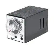


GT3F-1AF20
SOLID STATE TIMER, OFF-DELAY, SPDT, 5A
- Manufacturer: IDEC
- Product type: Analogue Timers
- Product Range:GT3 Series; Timer Functions:Off-Delay; No. of Timing Ranges:-; Time Min:0.1s; Time Max:600s; Timer Output:1 Changeover Relay; Supply Voltage Max:240
- SVHC: No SVHC (16-Jul-2019)
- Time Max: 600s
- Time Min: 0.1s
- Timer Output: 1 Changeover Relay
- Product Range: GT3 Series
- Timer Functions: Off-Delay
- Current Rating Nom: 5A
- Panel Cutout Width: 48mm
- Supply Voltage Max: 240VAC
- Panel Cutout Height: 48mm
- No. of Timing Ranges: -
- Connection / Termination: Screw Terminals
| Delivery and price | |
|---|---|
| Units per pack | 50 |
| Price | 64.11 € |
| Current stock | 10+ |
| Lead time | 22 days |
**GT3A**
**Timers**
## **GT3A Series — Analog Timers**
## **Key features:**
- 4 selectable operation modes on each model
- External start, reset, and gate inputs
- Panel mount or socket mount
- Large variety of timing functions
- Power and output status indicating LEDs
**==> picture [101 x 30] intentionally omitted <==**
**----- Start of picture text -----**<br>
UL, c-UL Listed<br>File No. E55996<br>CE<br>**----- End of picture text -----**<br>
## **Specifications**
||GT3A-1|GT3A-2|GT3A-3|GT3A-4,-5,-6|
|---|---|---|---|---|
|Operation<br>Time Range<br>Rated Voltage<br>Contact Ratings<br>Minimum Applicable Load<br>Voltage Tolerance<br>Error<br>Setting Error<br>Reset Time<br>Insulation Resistance<br>Dielectric Strength<br>Power Consumption<br>(approximate)<br>Mechanical Life<br>Electrical LIfe<br>Weight (approximate)<br>Vibration Resistance<br>Shock Resistance<br>Operating Temperature<br>Operating Humidity<br>Storage Temperature<br>Housing Color|Multi-mode<br>Multi-mode with inputs (11 pins)<br>0.1s to 180 hours<br>100 to 240V AC, 50/60Hz<br>12V DC<br>24V AC, 50/60Hz / 24V DC<br>125V AC/250V AC, 3A;<br>30V DC, 1A (resistive load)<br>125V AC/250V AC, 5A;<br>30V DC, 5A (resistive load)<br>5V, 10mA (reference value)<br>AF20 (100V AC): 85 to 264V AC<br>AD24: 20.4 to 26.4V AC/21.6 to 26.4V DC<br>D12: 10.8 to 13.2V DC<br>±0.2%, ±10 msec (repeat, voltage, temperature)<br>±10% maximum<br>60msec maximum<br>100MW minimum<br>Between power and output terminals: 2,000V AC, 1 minute<br>Between contacts of different poles: 2,000V AC, 1 minute<br>Between contacts of the same pole: 750V AC, 1 minute<br>Delayed SPDT<br>Delayed SPDT +<br>instantaneous SPDT<br>Delayed DPDT<br>Delayed DPDT<br>10.8VA<br>(200V AC, 60Hz)<br>13.5VA<br>(200V AC, 60Hz)<br>14.4VA<br>(200V AC, 60Hz)<br>4.7VA (100V AC, 60Hz),<br>14.4VA (200V AC, 60Hz)<br>—<br>12VDC/1W<br>24VDC/0.7W<br>24VAC/1.2VA<br>12VDC/1.1W<br>24VDC/0.6W<br>24VAC/1.3VA<br>12VDC/0.8W<br>24VDC/0.6W<br>24VAC/1.3VA<br>10,000,000 operations minimum<br>5,000,000 operations minimum<br>50,000 operations minimum (rated load)<br>100,000 operations minimum (rated load)<br>63g<br>73g<br>79g<br>80g<br>100m/sec2(approximate 10G)<br>Operating extremes: 100m/sec2(approximate 10G)<br>Damage limits: 500m/sec2(approximate 50G)<br>–10 to +50°C<br>45 to 85% RH<br>–30 to +80°C<br>Gray||||
1705151136
**800-262-IDEC** (4332) • USA & Canada
**951**
**GT3A**
**Timers**
## **Part Numbers**
## **GT3A-1, -2, -3**
|Mode Of<br>Operation<br>A: ON-delay 1<br>B: Interval 1<br>C: Cycle 1<br>D: Cycle 3|Rated Voltage Code<br>AF20: 100 to 240V AC (50/60Hz)<br>AF20: 100 to 240V AC (50/60Hz)<br>D12: 12V DC<br>AD24: 24V AC (50/60Hz)/24V DC|Time Range<br>0.1 seconds<br>to 180 hours|Output<br>250V AC, 3A,<br>30V DC, 1A<br>(resistive load)<br>240V AC, 5A,<br>24V DC, 5A<br>(resistive load)|Contact<br>Delayed SPDT<br>Delayed SPDT +<br>Instantaneous SPDT<br>Delayed DPDT|Complete Part No.<br>8-Pin<br>11-Pin<br>GT3A-1AF20<br>GT3A-1EAF20<br>GT3A-2AF20<br>GT3A-2EAF20<br>GT3A-2D12<br>GT3A-2ED12<br>GT3A-2AD24<br>GT3A-2EAD24<br>GT3A-3AF20<br>GT3A-3EAF20<br>GT3A-3D12<br>GT3A-3ED12<br>GT3A-3AD24<br>GT3A-3EAD24|
|---|---|---|---|---|---|
1. For wiring schematics and timing diagrams for GT3A-1, -2, -3, see pages page 940 and page 941 respectively.
2. For more details about time ranges, see instructions on page page 940.
3. For socket and accessory part numbers, see page 958.
## **GT3A-4, -5, -6**
|**GT3A-4, -5, -6**||||||||
|---|---|---|---|---|---|---|---|
|Mode of<br>Operation<br>A: ON-Delay 2<br>B: Cycle 2<br>C: Signal ON/OFF-Delay 1<br>D: Signal OFF-Delay 1|Rated Voltage Code<br>AF20: 100 to 240V AC (50/60Hz)<br>D12: 12V DC<br>AD24: 24V AC (50/60Hz)/24V DC|Time Range|Output|Contact|Input|Complete Part No.<br>A (11-pin)<br>B (11-pin)<br>GT3A-4AF20<br>GT3A-4EAF20<br>GT3A-4D12<br>GT3A-4ED12<br>GT3A-4AD24<br>GT3A-4EAD24||
|A: Interval 2<br>B: One-Shot Cycle<br>C: Signal ON/OFF-Delay 2<br>D: Signal OFF-Delay 2<br>A: One-Shot<br>B: One-Shot ON-Delay|AF20: 100 to 240V AC (50/60Hz)<br>AD24: 24V AC (50/60Hz)/24V DC|0.1 seconds<br>to 180 hours|250V AC, 5A,<br>24V DC, 5A<br>(resistive load)|Delayed<br>DPDT|Start<br>Reset<br>Gate|GT3A-5AF20<br>GT3A-5AD24<br>GT3A-6AF20|GT3A-5EAF20<br>GT3A-5EAD24<br>GT3A-6EAF20|
|C: One-Shot 2<br>D: Signal ON/OFF-Delay 3||||||GT3A-6AD24|GT3A-6EAD24|
4. For wiring schematics and timing diagrams GT3A-4,-5,-6, see pages 940, 941, and 941 respectively.
~~BO~~ 5. For more details about time ranges, see instructions on page 940. 6. A (11-pin) and B (11-pin) differ in the way inputs are wired.
7. For socket and accessory part numbers, see page 958.
8. For the timing diagrams overview, see page 940.
## —ipeEc
1705151136
**www.IDEC.com**
952
**GT3A**
**Timers**
## **Timing Diagrams/Schematics**
## **GT3A-1 Timing Diagrams Delayed SPDT**
Operation Mode Selection
**==> picture [560 x 178] intentionally omitted <==**
**----- Start of picture text -----**<br>
|||||||
|---|---|---|---|---|---|
|ON-Delay 1|Set Time|Item|Terminal Number|T|Operation|
|MODE|Power|2 - 7 (8p)2 - 10 (11p)|
|A|Delayed Contact|5 - 8 (8p)8 - 11 6 - 8 (8p)9 - 11 ((1111p)p)|(NC)(NO)|
|POWER|
|Indicator|=|
|OUT|
|rat|———|
|Interval 1|Item|Terminal Number|Operation|
|Set Time|T|
|MODE|Power|2 - 7 (8p)2 - 10 (11p)|
|<|B|Delayed Contact|5 - 8 (8p)8 - 11 6 - 8 (8p)9 - 11 ((1111p)p)|(NC)(NO)|——|
|POWER|
|Indicator|
|OUT|
|—s|
|Ww|——|
**----- End of picture text -----**<br>
**==> picture [191 x 189] intentionally omitted <==**
**----- Start of picture text -----**<br>
|||||||
|---|---|---|---|---|---|
|Cycle 1|Item|Terminal Number|Operation|
|(OFF first)|Set Time|T|T|
|MODE|PowerDelayed|2 - 7 (8p)2 - 10 5 - 8 (8p)8 - 11 ((1111p)p)|(NC)|a|
|C|Contact|6 - 8 (8p)9 - 11 (11p)|(NO)|
|POWER|
|ae|S|Indicator|tesn|
|OUT|
|GZ|—|
|Cycle 3|Item|Terminal Number|Operation|
|(ON first)|Set Time|T|T|
|MODE|PowerDelayed|2 - 7 (8p)2 - 10 5 - 8 (8p)8 - 11 ((1111p)p)|(NC)|
|=|D|Contact|6 - 8 (8p)9 - 11 (11p)|(NO)|—|
|POWER|
|Indicator|
|OUT|
|=n|
|WY|e|
**----- End of picture text -----**<br>
1705151136
**800-262-IDEC** (4332) • USA & Canada
953
**GT3A**
**Timers**
**==> picture [553 x 590] intentionally omitted <==**
**----- Start of picture text -----**<br>
||||||||||||||||||||||
|---|---|---|---|---|---|---|---|---|---|---|---|---|---|---|---|---|---|---|---|---|
|GT3A-2 Timing Diagrams|GT3A-3 Timing Diagrams|
|Delayed SPDT + Instantaneous SPDT|Delayed DPDT|
|8-Pin|@|Q|m|o|Q|8-Pin|@|Q|m|m|Q|
|Operation|Operation|
|Mode|Mode|
|Selection|Selection|
|Set Time|Item|Terminal Number|T|Operation|ON-Delay 1|Set Time|Item|Terminal Number|T|Operation|
|ON-Delay 1|Power|2 - 7 (8p)2 - 10 (11p)|MODE|Power|2 - 7 (8p)2 - 10 (11p)|—|
|MODE|A|Delayed Contact|6 - 8 (8p)9 - 11 5 - 8 (8p)8 - 11 ((1111p)p)|(NO)(NC)||—|A|Delayed Contact|1 -3, 6 - 8 (8p)1 -31 -4, 5 - 8 (8p)1 -4,, 9 - 11 8 - 11 ((1111p)p)|(NO)(NC)|
|Instantaneous Contact|1 - 4|(NC)|||Indicator|POWER|
|1 - 3|(NO)|OUT|
|POWER|
|6|Indicator|“=|=|OC|||||
|OUT|Interval 1|Item|Terminal Number|Operation|
|||Set Time|||T|||
|MODE|Power|2 - 7 (8p)2 - 10 (11p)|lJ|
|Interval 1|PowerSet Time|Item|2 - 7 (8p)2 - 10|Terminal Number|(11p)|T|Operation|B|Delayed Contact|1 -3, 6 - 8 (8p)1 -31 -4, 5 - 8 (8p)1 -4,, 9 - 11 8 - 11 ((1111p)p)|(NO)(NC)|
|MODE|B|Delayed Contact|6 - 8 (8p)9 - 11 5 - 8 (8p)8 - 11 ((1111p)p)|(NO)(NC)|||=-|©|Indicator|OUTPOWER|
|Instantaneous|1 - 4|(NC)|
|Contact|
|1 - 3|(NO)|———|Cycle 1|Item|Terminal Number|Operation|
|S|POWER|(OFF first)|Set Time|T|T|
|Indicator|OUT|——|MODE|Delayed Power|1 -4, 5 - 8 (8p)1 -42 - 7 (8p)2 - 10 , 8 - 11 (11p)(11p)|(NC)|ae|
|Item|Terminal Number|Operation|C|Contact|1 -3, 6 - 8 (8p)1 -3, 9 - 11 (11p)|(NO)|
|Cycle 1(OFF first)|Set TimePower|2 - 7 (8p)2 - 10 (11p)|T|T|Indicator|OUTPOWER|
|Delayed|5 - 8 (8p)8 - 11 (11p)|(NC)|7|-|a|
|MODE|Contact|6 - 8 (8p)9 - 11 (11p)|(NO)|
|wT|C|IndicatorInstantaneous Contact|POWER1 - 31 - 4|(NO)(NC)|=|||_|Cycle 3(ON first)|@|MODE|Delayed PowerSet Time|Item|1 -4, 5 - 8 (8p)1 -42 - 7 (8p)2 - 10|Terminal Number|, 8 - 11 (11p)(11p)|(NC)|_-|T|T|Operation|
|(Z)|OUT|—|D|Contact|1 -3, 6 - 8 (8p)1 -3, 9 - 11 (11p)|(NO)|my|||
|POWER|
|Indicator|
|Item|Terminal Number|Operation|OUT|
|Set Time|—|T|-|T|™|=a|||
|Cycle 3(ON first)|Power|2 - 7 (8p)2 - 10 (11p)|
|MODE|Delayed Contact|6 - 8 (8p)9 - 11 5 - 8 (8p)8 - 11 ((1111p)p)|(NO)(NC)|
|Ww|D|Instantaneous|1 - 4|(NC)|-_—|||
|Contact|
|1 - 3|(NO)|
|POWER|
|Indicator|
|WN|OUT|||||
**----- End of picture text -----**<br>
Note: Pins 1, 3, and 4 are the instantaneous contacts.
## —ipeEc
1705151136
**www.IDEC.com**
954
**GT3A**
**Timers**
_
## **GT3A-4 Timing Diagrams Delayed DPDT**
**==> picture [51 x 16] intentionally omitted <==**
**----- Start of picture text -----**<br>
Operation<br>Mode Selection<br>**----- End of picture text -----**<br>
**==> picture [558 x 544] intentionally omitted <==**
**----- Start of picture text -----**<br>
Item Terminal Number Operation<br>Power 2 - 10 POWER<br>ON-Delay 2 Start 2 - 6 (A)5 - 7 (B) ON or L<br>MODE ls| Input tLne Reset | 2 - 7 (A)6 - 7 (B) | ON or L ae oenOa—<br>Gate 2 - 5 (A) ON or L<br>A 1 - 4<br>Delayed 8 - 11 (NC)<br>Ww Contact 9 - 111 - 3 (NO) a — ss |C<br>POWER<br>6 —_= Indicator | OUT | apap 7 oe |<br>Set Time<br>ee ee T Set Ta ht T' T" 1<br>Item Terminal Number Operation<br>Power 2 - 10 POWER<br>Cycle 2 Start 2 - 6 (A)5 - 7 (B) ON or L<br>MODE ——————— | Input a Reset ee 2 - 7 (A)6 - 7 (B) ON or L a a a|<br>Gate 2 - 5 (A) ON or L<br>B 1 - 4<br>Delayed 8 - 11 (NC)<br>Contact 9 - 111 - 3 (NO)<br>POWER<br>Indicator<br>OUT<br>eee OTOL OT eee eC roro<br>Set Time<br>bo T | T T ae T | T |,_»| T T Pep Ta T | T T |_| T" L ev T" T |g»! T T | T T |<br>Item Terminal Number Operation<br>Power 2 - 10 POWER<br>Signal ON/OFF-Delay 1 | L_| Start 2 - 6 (A)5 - 7 (B) || ON or L ee ee a ee<br>MODE ee Input Reset 2 - 7 (A)6 - 7 (B) ON or L |<br>Gate 2 - 5 (A) ON or L<br>= C Delayed 8 - 11 || 1 - 4 (NC) es ee eee a |<br>Contact 9 - 111 - 3 (NO)<br>POWER<br>J) UC Indicator ee=<br>OUT | watt NT TT<br>Set Time<br>T T Ta T Ta T T T T" Ta<br>Poeee<br>Item Terminal Number Operation<br>Power 2 - 10 POWER<br>Signal OFF-Delay 1 CT | | Start _ | 2 - 6 (A)5 - 7 (B) — | ON or L — a a _ |a |<br>MODE Input | Reset a 2 - 7 (A)6 - 7 (B) ON or L ee|a a _ Oo |<br>Gate 2 - 5 (A) ON or L<br>D 1 - 4<br>Ww Delayed 8 - 11 (NC) a a _ ns —_— + 4§& 4 io<br>Contact 9 - 111 - 3 (NO)<br>POWER<br>Indicator<br>| — OUT | a a __ |<br>S eS Set Time<br>a T Ta Ta T T T<br>T = Set time Ta = Shorter than set time<br>T = T' + T"<br>Relays & Sockets<br>Timers<br>Contactors<br>Terminal Blocks<br>Circuit Breakers<br>**----- End of picture text -----**<br>
1705151136
**800-262-IDEC** (4332) • USA & Canada
955
**GT3A**
**Timers**
## **GT3A-5 Timing Diagrams Delayed DPDT**
**==> picture [564 x 688] intentionally omitted <==**
**----- Start of picture text -----**<br>
GT3A-5 Timing Diagrams<br>Delayed DPDT<br>(A Type)<br>(Contact Input) (Transistor Input) (B Type)<br>Operation } d b S © Qo Reset J Start J Gate o © Qo a = © © Qo<br>Mode Selection<br>A "03 +5" (0 6 "0oy| POWER: |o m6 ) “0a| [POWER] +"| (0<br>Item Terminal Number Operation<br>Power 2 - 10 POWER<br>Interval 2 Start 2 - 6 (A)5 - 7 (B) ON or L<br>— MODE i | Input ee Reset 2 - 7 (A)6 - 7 es (B) ON or L ee a———————————————————ee ee |<br>Gate 2 - 5 (A) ON or L<br>A 1 - 4<br>Delayed 8 - 11 (NC)<br>W | Contact 9 - 111 - 3 4 (NO) a es es a<br>POWER<br>0 Indicator a ~ — oo<br>OUT<br>| O | | — — |<br>ns Set Time oe OO OO | rs Oa |<br>| T Ta T' T"<br>Item Terminal Number Operation<br>Power 2 - 10 POWER<br>One-Shot Cycle ae Start 2 - 6 (A)5 - 7 (B) ON or L :<br>MODE ea Input Reset 2 - 7 (A)6 - 7 (B) ON or L<br>Gate 2 - 5 (A) ON or L<br>B 1 - 4<br>Delayed 8 - 11 (NC)<br>w Se Contact 9 - 111 - 3 (NO) —— —_——<br>POWER<br>8 Indicator aa<br>| | OUT | ; sd | | {| |<br>Set Time<br>| __{ | T T _ T em Ta | T' | | T" T ——<br>Item Terminal Number Operation<br>Power 2 - 10 POWER<br>Signal ON/OFF-Delay 2 Start 2 - 6 (A)5 - 7 (B) ON or L<br>———_——————————————<br>MODE | Input Reset 2 - 7 (A)6 - 7 (B) ON or L — a 4<br>Gate 2 - 5 (A) ON or L<br>C Delayed 8 - 111 - 4 (NC) — i<br>= Contact EP 9 - 111 - 3 (NO) oe 7 a a<br>POWER<br>eee Indicator _ i:<br>OUT or eoee<br>Set Time<br>T T Ta T Ta Ta T T' T" Ta<br>Item Terminal Number Operation<br>Power 2 - 10 POWER<br>Signal OFF-Delay 2 — Start —$——<——<—_—<—_ 2 - 6 (A)5 - 7 (B) ON or L<br>MODE ee Input Reset 2 - 7 (A)6 - 7 (B) ee ON or L oT<br>Gate 2 - 5 (A) ON or L<br>D 1 - 4<br>Delayed 8 - 11 (NC)<br>Contact 9 - 111 - 3 (NO)<br>POWER<br>5 Indicator ——<br>OUT<br>See eee 7<br>rs Set Time |__| rs Pare | l g» ! |<br>pe T Ta Ta T T' T"<br>T = Set time Ta = Shorter than set time<br>T = T' + T"<br>Switches & Pilot Lights<br>Signaling Lights<br>Relays & Sockets<br>Timers<br>Contactors<br>Terminal Blocks<br>Circuit Breakers<br>**----- End of picture text -----**<br>
—ipeEc
1705151136
**www.IDEC.com**
956
**GT3A**
**Timers**
## **GT3A-6 Timing Diagrams Delayed DPDT**
**==> picture [536 x 614] intentionally omitted <==**
**----- Start of picture text -----**<br>
Operation<br>Mode Selection<br>Item Terminal Number Operation<br>Power 2 - 10 POWER<br>One-Shot 1 Start 2 - 6 (A)5 - 7 (B) ON or L<br>MODE | Input |}ee Reset 2 - 7 (A)6 - 7 (B) ON or L eet— — a————————<br>Gate 2 - 5 (A) ON or L<br>A 1 - 4<br>Delayed 8 - 11 (NC)<br>Contact 9 - 111 - 3 (NO)<br>a POWER a E<br>S Indicator<br>OUT<br>a peon o_o_h | |<br>Set Time<br>cc Ta Ta T Ta T' T"<br>Item Terminal Number Operation<br>Power 2 - 10 POWER<br>One-Shot ON-Delay Pt Start 2 - 6 (A)5 - 7 (B) ON or L<br>MODE |; Input Reset }tt 2 - 7 (A)6 - 7 (B) ON or L ——E_——e<br>Gate 2 - 5 (A) ON or L<br>B 1 - 4<br>w | Delayed a 8 - 11 (NC) - — — |<br>Contact 9 - 111 - 3 (NO)<br>POWER<br>S ee Indicator ee<br>OUT<br>eReTm Ra et -<br>Set Time<br>= fal T fl T fo Ta T T |is T' 7 T" _ |<br>Item Terminal Number Operation<br>Power 2 - 10 POWER<br>One-Shot 2 — | re Start 2 - 6 (A)5 - 7 (B) ee ——<—<——<—_ ON or L a a at<br>MODE O Input g a Reset 2 - 7 (A)6 - 7 (B) ON or L a<br>Gate 2 - 5 (A) ON or L<br>C Delayed 8 - 111 - 4 (NC) — a<br>C—O Contact 9 - 111 - 3 (NO)<br>POWER<br>Q Indicator = =<br>OUT =<br>—<br>Set Time<br>cc T Ta T T' T"<br>Item Terminal Number Operation<br>Power 2 - 10 POWER<br>Signal ON/OFF-Delay 3 TT Start 2 - 6 (A)5 - 7 (B) ON or L<br>MODE a Input Reset a 2 - 7 (A)6 - 7 (B) ON or L ee |<br>Gate 2 - 5 (A) ON or L<br>D 1 - 4<br>Delayed 8 - 11 (NC)<br>W 7 Contact 9 - 111 - 3 a (NO) ee ee Z ——<br>POWER<br>Indicator<br>OUT<br>Set Time<br>| T | T ae Ta T' T" Ta Ta T<br>T = Set time Ta = Shorter than set time<br>T = T' + T"<br>**----- End of picture text -----**<br>
1705151136
**800-262-IDEC** (4332) • USA & Canada
957
**GT3A**
**Timers**
## **Instructions: Setting GT3A Series Timers**
Timed OUT Indicator POWER Indicator (flashes during time-delay period) ie: 02 aS» .: : — Ww F m Setting Knob j Operator Mode Selector l Time Range Selector A, B, C, D 1S, 10S, 10M, 10H
k Dial Selector **0-1, 0-3, 0-6, 0-18**
|Relays & Sockets||Step1.|Desired Mode of Operation<br>**For Timers**<br>**Mode of Operation**<br>GT3A-1<br>GT3A-2<br>GT3A-3<br>ON-delay1<br>Interval 1<br>Cycle 1<br>Cycle 3|Selection<br>j**Operation Mode Selector**<br>A<br>B<br>C<br>D|Selection<br>j**Operation Mode Selector**<br>A<br>B<br>C<br>D|Remarks|
|---|---|---|---|---|---|---|
|**Timers**||Select the desired mode<br>of operation.|GT3A-4<br>ON-delay2<br>Cycle 2<br>Signal ON/OFF-delay1<br>Signal OFF-delay1<br>GT3A-5<br>Interval 2<br>One-shot cycle<br>Signal ON/OFF-delay2||A<br>B<br>C<br>D<br>A<br>B<br>C|The desired operation mode can be selected from<br>the A, B, C, and D modes using the Operation Mode<br>Selector. Change the operation mode from A to B, C,<br>and D in turn by turning the operation mode selector<br>clockwise using a flat screwdriver which is a maximum<br>of 0.156” (4mm) wide. The selected mode is displayed<br>in the window.|
||||Signal OFF-delay2||D||
||||One-shot 1||A||
||||GT3A-6<br>One-shot ON-delay<br>One-shot 2||B<br>C||
|Contactors||Step2.|Signal ON/OFF-delay 3<br>Desired Time Range<br>**Time Ranges**<br>0.1 seconds to 1 second|D<br>Selection<br>k**Dial Selector**<br>l**Time Range Selector**<br>0-1||Remarks|
||||0.1 seconds to 3 seconds<br>0.1 seconds to 6 seconds|0-3<br>0-6|1S||
||||0.15 seconds to 18 seconds|0-18|||
||||0.1 seconds to 10 seconds|0-1|||
|Terminal Blocks||Select the time range<br>that contains the desired<br>time period.|0.3 seconds to 30 seconds<br>0.6 seconds to 60 seconds<br>1.8 seconds to 180 seconds<br>6 seconds to 10 minutes<br>18 seconds to 30 minutes<br>36 seconds to 60 minutes|0-3<br>0-6<br>0-18<br>0-1<br>0-3<br>0-6|10S<br>10M|The desired time range is selected by setting both<br>kDial Selector and<br>lTime Range Selector.|
||||108 seconds to 180 minutes|0-18|||
||||6 minutes to 10 hours|0-1|||
|Circuit Breakers||Step3.<br>Set the precise period of time desired by using the|18 minutes to 30 hours<br>36 minutes to 60 hours<br>108 minutes to 180 hours<br>Set the precise period of time desired by using themSetting Knob.|0-3<br>0-6<br>0-18|10H<br>Selection||
—ipeEc
1705151136
**www.IDEC.com**
958
**GT3F**
**Timers**
## **GT3F Series — True Power OFF Delay Timers**
## **Key features:**
- “True” power OFF-delay up to 10 minutes
- No external control switch necessary
- Available with reset inputs
- Mountable in sockets or flush panel
**==> picture [101 x 31] intentionally omitted <==**
**----- Start of picture text -----**<br>
UL, c-UL Listed<br>File No. E55996<br>CE<br>**----- End of picture text -----**<br>
## **Specifications**
|~~rs~~|GT3F-1<br>~~rs~~|GT3F-2<br>~~rs~~|
|---|---|---|
|Operation<br>Time Range<br>Rated Voltage<br>Contact Rating<br>Contact Form<br>Minimum Power Application Time<br>Voltage Tolerance<br>Repeat Error<br>Voltage Error<br>Temperature Error<br>Setting Error<br>Insulation Resistance<br>Dielectric Strength<br>Power Consumption<br>Mechanical Life<br>Electrical Life<br>Vibration Resistance<br>Shock Resistance<br>Operating Temperature<br>Storage Temperature<br>Operating Humidity<br>Weight (approximate)<br>~~rs~~<br>|<br>|<br>|<br>|<br>|<br>|<br>|<br>|<br>|<br>|<br>|<br>|<br>||True power OFF-delay<br>0.1 seconds to 600 seconds<br>100 to 240V AC, 50/60Hz<br>24V AC/DC<br>250V AC/24V DC, 5A<br>(resistive load)<br>250V AC/24V DC, 3A<br>(resistive load)<br>SPDT<br>DPDT<br>1 second<br>AF20: 100 to 240V AC<br>AD24: 21.6 to 26.4VDC, 20.4 to 26.4VAC<br>±0.2%, ±10 msec<br>±0.2%, ±10 msec<br>±0.2%, ±10 msec<br>±10% maximum<br>100MW minimum<br>Between power and output terminals:<br>2,000V AC, 1 minute (SPDT)<br>1,500V AC, 1 minute (DPDT)<br>Between contacts on different poles:<br>1,000V AC, 1 minute (DPDT)<br>Between contacts of the same pole:<br>750V AC, 1 minute<br>AF20: 3.7VA (200V AC, 60Hz)<br>AD24: 0.8W (DC), 1.2VA (AC)<br>3,000,000 operations minimum<br>100,000 operations minimum<br>100m/sec2(approximate 10G)<br>Operating extremes:<br>100 m/sec2(approximate 10G)<br>Damage limits: 500 m/sec2(approximate 50G)<br>–10 to +50°C<br>–30 to +80°C<br>45 to 85% RH<br>77g<br>79g<br>~~rs~~<br>|<br>|<br>|<br>|<br>|<br>|<br>|<br>|<br>|<br>|<br>|<br>|<br>|<br>|<br>|||
1. An inrush current flows during the minimum power application time. AF20: approximate 0.4A, AD24: approximate 1.2A
2. GT3F does not read the preset time range shown on the knob after power is turned off. Note that minimizing the preset time, by turning the knob to zero, does not shorten the delay time after power is removed.
1705151136
**800-262-IDEC** (4332) • USA & Canada
959
**GT3F**
**Timers**
## **Part Numbering List**
## **GT3F**
|Mode of<br>Operation<br>True-Power|Rated<br>Voltage Code<br>AF20: 100 to<br>240VAC (50/60Hz)|Time Range<br>0.1 seconds to|Output<br>250V AC, 5A,<br>30V DC, 5A (resistive load)|Contact<br>Delayed SPDT|Optional Input<br>Reset|Complete Part Number<br>8-Pin<br>11-Pin<br>GT3F-1AF20<br>GT3F-1EAF20<br>GT3F-1AD24<br>GT3F-1EAD24|
|---|---|---|---|---|---|---|
|OFF-delay|AD24: 24V AC/DC|600 seconds|250V AC, 3A,<br>30V DC, 3A (resistive load)|Delayed DPDT|None (8p)<br>Reset (11p)|GT3F-2AF20<br>GT3F-2EAF20<br>GT3F-2AD24<br>GT3F-2EAD24|
Optional reset input resets the contact to the OFF state before time out.
## **Timing Diagrams/Schematics**
## **GT3F-1 Timing Diagrams**
GT3F-1 (8-pin)
GT3F-1E (11-pin)
Delayed SPDT Output, with Reset Input
**==> picture [310 x 84] intentionally omitted <==**
**----- Start of picture text -----**<br>
Item Terminal Number Operation<br>Power 2 - 10 2 - 7 (8p)(11p) | | | | |<br>Reset Input 6 - 7 1 - 4 (8p)(11p) ON or L |__| |__| iom|<br>Delayed 1 - 4 (11p)5 - 8 (8p) (NC) aa | _ im |<br>Contact 1 - 3 6 - 8 (8p)(11p) (NO)<br>Indicator POWER<br>=<br>Set Time ——<br>Tr T Ta Ts T<br>**----- End of picture text -----**<br>
T = Set time Ta = Shorter than set time Ts = 1 Second Tr = Minimum Power Application Time GT3F-1: 1 Second
1. For time ranges, see page page 941.
2. For sockets and accessory part numbers, see page page 967.
3. When power is applied, the NO output contact closes. When power is removed, the timing period begins. When time has elapsed, the NO contact opens.
4. For the timing diagram overview, see page page 940.
Hipec
1705151136
**www.IDEC.com**
960
**GT3F**
**Timers**
## **GT3F-2 Timing Diagrams**
**==> picture [512 x 330] intentionally omitted <==**
**----- Start of picture text -----**<br>
GT3F-2 (8-pin) GT3F-2E (11-pin)<br>Delayed DPDT Output<br>(Contact Input) (Transistor Input)<br><br> [] [] <br> <br> <br>(-) (+) <br>(-) (+) (-) (+)<br> <br>POWER POWER POWER<br>Item Terminal Number Operation<br>Power a [d] 2 - 7 [a] [le]<br>Delayed 1 - 4 5 - 8 (NC)<br>8-Pin Type Contact 1 - 3 6 - 8 (NO)<br>Indicator POWER<br>Set Time<br>ee T Tr T<br>Item Terminal Number Operation<br>Power 2 - 10<br>Reset Input 6 - 7 (11p) ON or L<br>11-Pin Type Delayed 8 - 111 - 4 (NC)<br>Contact 9 - 111 - 3 (NO)<br>Indicator POWER<br>Set Time<br>Tr T Ta Ts T<br>**----- End of picture text -----**<br>
When power is applied, the NO contact closes. When power is removed, the timing period begins. When time has elapsed, the NO contact opens. Optional reset input will return contacts to original state before time elapses.
T = Set time Ta = Shorter than set time Ts = 1 Second Tr = Minimum Power Application Time GT3F-1: 1 Second
**==> picture [309 x 84] intentionally omitted <==**
**----- Start of picture text -----**<br>
Item Terminal Number Operation<br>Power 2 - 10<br>Reset Input 6 - 7 (11p) ON or L<br>Delayed 8 - 111 - 4 (NC)<br>Contact 9 - 111 - 3 (NO)<br>Indicator POWER<br>Set Time<br>Tr T Ta Ts T<br>**----- End of picture text -----**<br>
1705151136
**800-262-IDEC** (4332) • USA & Canada
961
**GT3F**
**Timers**
## **Instructions: Setting GT3F Series Timers**
POWER Indicator
l Setting Knob
j Dial Selector 0-1, 0-3, 0-6, 0-18, 0-60
k Time Range Selector 1S, 10S
|Step 1|Desired Operation|Selection|Selection|Remarks|
|---|---|---|---|---|
||Base Time Ranges|jDial Selector|kTime Range<br>Selector||
||0.1s to 1s|0 to 1|||
|Select a time<br>range that<br>contains the<br>desired period<br>of time.|0.1s to 3s<br>0.1s to 6s<br>0.1s to 10s<br>0.3s to 30<br>0.6s to 60|0 to 3<br>0 to 6<br>0 to 1<br>0 to 3<br>0 to 6|1s<br>10s|Time range can be selected from 1S and 10S using a flat screwdriver and five different<br>dials of 0 to 1, 0 to 3, 0 to 6, 0 to 18, and 0 to 60 are displayed in the six windows by<br>turning the Dial Selector, allowing for selecting the best suited scale. Note that the<br>switch does not turn infinitely.|
||1.8s to 180s|0 to 18|||
||6s to 600s|0 to 60|||
||Step 2|||Remarks|
|The set time is selected by turning thelSetting Knob.||||Setting Examples:<br>1. When the Setting Knoblis set at 2.5, with Dial Selectorj0 to 3 and Time Range<br>Selectork1S selected, then the set time is 2.5 seconds.<br>2. When the Setting Knoblis set at 5.0, with Dial Selectorj0 to 60 and Time Range<br>Selectork10S selected, then the set time is 500 seconds.|
## **Instructions: Wiring Inputs**
## **Inputs of GT3F**
To avoid electric shock, do not touch the input signal terminal during power voltage application. Never apply the input signals to two or more GT3F timers using the same contact or transistor.
**==> picture [255 x 71] intentionally omitted <==**
**----- Start of picture text -----**<br>
[Incorrect] GT3 Series<br>Input Contact or Transistor Timer [correct]<br>Input Input<br>Terminal Terminal<br>2 10 Power 2 10 Power<br>Input Input<br>Terminal Terminal<br>2 10 2 10<br>Ho) Bit<br>**----- End of picture text -----**<br>
In a transistor circuit for controlling input signals, with its primary and secondary power circuits isolated, do not ground the secondary circuit.
##
**==> picture [153 x 83] intentionally omitted <==**
**----- Start of picture text -----**<br>
GT3 Series<br>Timer<br>Input<br>Terminal<br>Power<br>Circuit<br>‘ (a<br>Insulating Transformer f<br>Terminal Blocks<br>Rectifier Circuit<br>**----- End of picture text -----**<br>
On the GT3F timers, connect the input signals to terminal No.1 and 4 only on the 8-pin type; connect the input signals to terminal No. 6 and 7 only on the 11-pin type. Never apply voltage to other terminals; otherwise, the internal circuit may be damaged. Input signal lines must be made as short as possible and installed away from power cables and power lines. Use shielded wires or a separate conduit for input wiring. The GT3F, consisting of a high-impedance circuit, may not be reset due to the influence of an inductive voltage or residual voltage caused by a leakage current. If not reset, connect an RC filter or bleeder resistor between power terminals so that the voltage between power terminals can be reduced to less than 15% of the rated voltage.
—ipeEc
1705151136
**www.IDEC.com**
962
**GT3W**
**Timers**
## **GT3W Series — Dual Time Range Timers**
## **Key features:**
- Sequential start, sequential interval, on-delay, recycler, and interval ON timing functions
- 2 time settings in one timer
- 8 selectable operation modes on each model
- Mountable in sockets or flush panel
- Power and output status indicating LEDs
- Time ranges up to 300 hours
UL, c-UL Listed File No. E55996
## **General Specifications**
|Operation System<br>Operation Type<br>Time Range<br>Pollution Degree<br>Over Voltage Category<br>Rated Operational Voltage<br>AF20<br>AD24<br>D12<br>Voltage Tolerance<br>AF20<br>AD24<br>D12<br>Disengaging Value of Input Voltage<br>Range of Ambient Operating Temperature<br>Range of Ambient Storage<br>and Transport Temperature<br>Range of Relative Humidity<br>Atmospheric Pressure<br>Reset Time<br>Repeat Error<br>Voltage Error<br>Temperature Error<br>Setting Error<br>Insulation Resistance<br>Dielectric Strength<br>Vibration Resistance<br>Shock Resistance<br>Degree of Protection<br>Power Consumption<br>(Approx.)<br>AF20<br>100V AC/60Hz<br>200V AC/60Hz<br>AD24 (AC/DC)<br>Mounting Position<br>Dimensions<br>Weight (Approx.)|Solid state CMOS Circuit<br>Multi-Mode<br>1: 0.1sec to 6 hours, 3: 0.1sec to 300 hours<br>2 (IE60664-1)<br>III (IE60664-1)<br>100-240V AC(50/60Hz)<br>24V AC(50/60Hz)/24V DC<br>12V DC<br>85-264V AC(50/60Hz)<br>20.4-26.4V AC(50/60Hz)/21.6-26.4V DC<br>10.8-13.2V DC<br>Rated Voltage x10% minimum<br>-10 to +50ºC (without freezing)<br>-30 to +75ºC (without freezing)<br>35 to 85%RH (without condensation)<br>80kPa to 110kPa (Operating), 70kPa to 110kPa (Transport)<br>60msec maximum<br>±0.2%, ±10msec*<br>±0.2%, ±10msec*<br>±0.6%, ±10msec*<br>±10% maximum<br>100MΩ minimum (500V DC)<br>Between power and output terminals: 2000V AC, 1 minute<br>Between contacts of different poles: 2000V AC, 1 minute<br>Between contacts of the same pole:750V AC, 1 minute<br>10 to 55Hz amplitude 0.75mm2hours in each of 3 axes<br>Operating extremes: 98m/sec2(approx.10G)<br>Damage limits: 490m/sec2(approx. 50G)<br>3 times in each of 3 axes<br>IP40 (enclosure), IP20 (socket) (IEC60529)<br>2.3VA<br>4.6VA|
|---|---|
||1.8VA/0.9W<br>Free<br>40Hx 36W x 70 mm<br>72g|
## **Contact Ratings**
|Allowable Contact Power<br>Allowable Voltage<br>Allowable Current<br>Maximum permissible<br>operating frequency<br>Rated Load<br>Conditional Short Circuit<br>Life<br>Electrical<br>Mechanical|960VA/120W<br>250V AC/150V DC<br>5A<br>1800 cycles per hour<br>1/8HP, 240V AC<br>3A, 240V AC (Resistive)<br>5A, 120V AC/30V DC<br>(Resistive)<br>Fuse 5A, 250V<br>100,000 op. minimum<br>(Resistive)<br>20,000,000 op. minimum|
|---|---|
* For the value of the error against a preset time, whichever the largest applies.
1705151136
**800-262-IDEC** (4332) • USA & Canada
963
**GT3W**
**Timers**
## **Part Number List**
## **Part Numbers**
|Mode of Operation|Output|Contact|Time Range*|Rated Voltage<br>100 to 240V AC<br>(50/60Hz)|Pin Configuration<br>8 pin<br>11 pin|New Part Numbers<br>GT3W-A11AF20N<br>GT3W-A11EAF20N|
|---|---|---|---|---|---|---|
|A: Sequential Start<br>B: On-delay with course and fine<br>C: Recycler and instaneous<br>D: Recycler outputs (OFF Start)<br>E: Recycler outputs (ON Start)<br>F: Interval ON<br>G: Interval ON Delay<br>H: Sequential<br>Interval|3A, 240V AC<br>5A, 120V AC/30V DC<br>(Resistive Load)|Delayed<br>SPDT<br>+<br>Delayed<br>SPDT|1: 0.1sec - 6 hours<br>*(See Time Range<br>Settings for details.)|24V AC/DC<br>12V DC|8 pin<br>11 pin<br>8 pin<br>11 pin|GT3W-A11AD24N<br>GT3W-A11EAD24N<br>GT3W-A11D12N<br>GT3W-A11ED12N|
||||3: 0.1sec - 300 hours|100 to 240V AC<br>(50/60Hz)<br>24V AC/DC|8 pin|GT3W-A33AF20N<br>GT3W-A33AD24N|
1. For timing diagrams and schematics, see page 940.
2. For socket and accessory part number information, see page 959.
3. 8- and 11-pin models differ only in the number of pins (extra pins are not used).
4. For the timing diagram overview, see page 940. 5. *For details on setting time ranges, see the instructions on page 941.
|Time Range Code: 1<br>~~———s —}+—_~~|Time Range Code: 1<br>~~———s —}+—_~~|Time Range Code: 1<br>~~———s —}+—_~~|Time Range Code: 3<br>~~—}+—_~~————~~——_~~|Time Range Code: 3<br>~~—}+—_~~————~~——_~~|Time Range Code: 3<br>~~—}+—_~~————~~——_~~|
|---|---|---|---|---|---|
|Time Range<br>Selector<br>~~—~~|Scale<br>~~———s —}+—_~~|Time Range<br>~~—}+—_~~|Time Range<br>Selector<br>~~—}+—_~~|Scale<br>~~—}+—_~~————|Time Range<br>~~——_~~|
|1S<br>0-1<br>0.1 sec - 1 sec<br>10S<br>0.3 sec - 10 sec<br>10M<br>15 sec - 10 min<br>~~— ——s —}+—_~~<br>~~a~~<br>~~rs~~|||1S<br>0 - 3<br>0.1 sec - 3 sec<br>1M<br>3 sec - 3 min<br>1H<br>3 min - 3 hours<br>~~—}+—_~~ ———— ~~——_~~<br>~~a~~|||
|1S<br>0 - 6<br>0.1 sec - 6 sec<br>10S<br>1 sec - 60 sec<br>1M<br>6 sec - 6 min<br>10M<br>1 min - 60 min<br>1H<br>6 min - 6 hours<br>~~a~~<br>~~——~~<br>~~a~~|||1S<br>0 - 30<br>0.6 sec - 30 sec<br>1M<br>36 sec - 30 min<br>1H<br>36min - 30 hours<br>10H<br>6 hours - 300 hours<br>~~———~~<br>~~a~~<br>~~a~~|||
—ipeEc
1705151136
**www.IDEC.com**
964
**GT3W**
**Timers**
## **Timing Diagrams/Schematics**
**==> picture [508 x 490] intentionally omitted <==**
**----- Start of picture text -----**<br>
Mode Operation Chart Mode Operation Chart<br>Item TerminalNo. Operation Description Item TerminalNo. Operation Description<br>ee PO<br>Power 2-7 Power 2-7<br>HE<br>—i— DelayedContactRy1 ce (NC)(NO)1-41-3 ON after T1 DelayedContactRy1 ((1-41-3NCNO)) | ON during T1OFF during T2<br>5-8 5-8<br>——. DelayedContactRy2 ((NO)6-8NC) ON after T1 + T2 DelayedContactRy2 eta ((6-8NCNO)) ae ON during T1OFF during T2<br>OUT1 OUT1<br>Indicator Indicator<br>OUT2 OUT2<br>Sa oe<br>Set Time T1 T2 Set Time T1 T2<br>= Item TerminalNo. Operation Description ASS Item TerminalNo. Operation Description<br>Power 2-7 Power 2-7<br>—<br>DelayedContact (NC)1-41-3 DelayedContact (1-41-3NC)<br>== Ry1 (NO) ON after T1 + T2 | FE Ry1 (NO) —_ ON during T1<br>5-8 5-8<br>Delayed (NC) Delayed (NC)<br>Contact 6-8 Contact 6-8 ON after T1,<br>Ry2 (NO) ON after T1 + T2 Ry2 (NO) during T2<br>OUT1 OUT1<br>Indicator Indicator<br>OUT2 OUT2<br>ia = = —<br>Set Time T1 = T2 Set Time oe T1 T2<br>= Item TerminalNo. Operation Description Item TerminalNo. Operation Description<br>Power 2-7 Power 2-7<br>—— ——<br>1-4 1-4<br>DelayedContact (1-3NC) DelayedContact (1-3NC)<br>—— Ry1 (NO) Instantaneous ON | [=] Ry1 (NO) ON during T1<br>5-8 5-8<br>A DelayedContactRy2 ((6-8NCNO)) OFF during T1ON during T2 DelayedContactRy2 ((6-8NCNO)) a ON after T1 + T2<br>OUT1 OUT1<br>Indicator Indicator<br>OUT2 OUT2<br>fae-2-2e ——oaE: |<br>—— | | etie<br>Set Time T1 T2 Set Time T1 T2<br>= Item TerminalNo. Operation Description Item TerminalNo. Operation Description<br>Power 2-7 Power 2-7<br>=<br>1-4 1-4<br>SS DelayedContactRy1 ((1-3NCNO)) OFF during T1ON during T2 DelayedContactRy1 (NC)(NO)1-3 ON during T1 + T2<br>5-8 5-8<br>eS DelayedContactRy2 ((6-8NCNO)) OFF during T1ON during T2 DelayedContactRy2 Ht ((NO)6-8NC) ~ ON after T1,during T2<br>OUT1 OUT1<br>Indicator Indicator<br>OUT2 OUT2<br>PeReaoa= | Cet==<br>ae =~<br>Set Time T1 T2 Set Time T1 T2<br>Sa ca|| | -<br>Signaling Lights<br>A: Sequential Start<br>E: Recycler outputs (ON Start)<br>Relays & Sockets<br>F: Interval ON<br>B: On-delay with course and fine Timers<br>G: Interval ON Delay<br>Contactors<br>C: Recycler and instantaneous<br>H: Sequential Interval Terminal Blocks<br>D: Recycler outputs (OFF Start)<br>**----- End of picture text -----**<br>
1705151136
**800-262-IDEC** (4332) • USA & Canada
965
**GT3W**
**Timers**
T2 Time Range Selector Operation Mode Selector T1 Time Range Selector
## **Instructions: Setting GT3W Timer**
1. The switches should be securely turned using a flat screwdriver 4mm wide (maximum). Note that incorrect setting may cause malfunction. The switches, which do not turn infinitely, should not be turned beyond their limits.
T2 Setting Knob T1 Setting Knob
2. Since changing the setting during timer operation my cause malfunction, turn power off before changing.
## **Safety Precautions**
- Special expertise is required to use Electronic Timers. • All Electronic Timer modules are manufactured under IDEC’s rigorous quality control system, but users must add a backup or fail safe provision to the control system when using the Electronic Timer in applications where heavy damage or personal injury may occur should the Electronic Timer fail.
## **Caution**
Caution notices are used where inattention might cause personal injury or damage to equipment.
- The Electronic Timer is designed for installation in equipment. Do not install the Electronic Timer outside equipment.
- Install the Electronic Timer according to instructions described in this catalog.
- Install the Electronic Timer in environments described in the specifications. If the Electronic Timer is used in places where it will be subjected to high-temperature, high-humidity, condensation, corrosive gases, excessive vibrations, or excessive shocks, then electrical shocks, fire hazard, or malfunction could result.
- Make sure that the operating conditions are as described in the specifications. If you are uncertain about the specifications, contact IDEC in advance.
- In these directions, safety precautions are categorized in order of importance to Warning and Caution.
- Use an IEC60127-approved fuse and circuit breaker on the power and output line outside the Electronic Timer.
## **Warning**
- Do not disassemble, repair, or modify the Electronic Timer.
Warning notices are used to emphasize that improper operation may cause sever personal injury or death.
- When disposing of the Electronic Timer, do so as industrial waste.
- Turn power off to the Electronic timer before starting installation, removal, Wiring, maintenance, and inspection on the Electronic Timer.
- Failure to turn power off may cause electrical shocks or fire hazard. • Emergency stop and interlocking circuits must be configured outside the Electronic timer. If such a circuit is configured inside the Electronic Timer, failure of the Electronic timer may cause malfunction of the control system, or an accident.
1705151136
**www.IDEC.com**
966
**GT3 Series Accessories**
**Timers**
## **GT3 Series**
## **Accessories**
## **DIN Rail Mounting Accessories**
## **DIN Rail/Surface Mount Sockets and Hold-Down Springs**
**==> picture [526 x 573] intentionally omitted <==**
**----- Start of picture text -----**<br>
DIN Rail Mount Socket Applicable Hold-Down Springs<br>Style Appearance Use with Timers Part No. Appearance Part No.<br>GT3A-1, 2, 3 (8-pin)<br>8-Pin Screw Terminal<br>GT3F-1, 2 (8-pin) SR2P-05<br>(dual tier)<br>GT3W (8-pin)<br>GT3A-1, 2, 3 (11-pin)<br>11-Pin Screw Terminal GT3A-4, 5, 6<br>SR3P-05<br>(dual tier) GT3F-1, 2 (11-pin)<br>GT3W (11-pin)<br>SFA-203<br>GT3A-1, 2, 3 (8-pin)<br>8-Pin Fingersafe Socket GT3F-1, 2 (8-pin) SR2P-05C<br>GT3W (8-pin)<br>a a,<br>GT3A-1, 2, 3 (11-pin)<br>GT3A-4, 5, 6<br>11-Pin Fingersafe Socket SR3P-05C<br>GT3F-1, 2 (11-pin)<br>GT3W (11-pin)<br>GT3A-1, 2, 3 (8-pin)<br>8-Pin Screw Terminal GT3F-1, 2 (8-pin) SR2P-06<br>GT3W (8-pin)<br>SFA-202<br>GT3A-1, 2, 3 (11-pin)<br>GT3A-4, 5, 6<br>11-Pin Screw Terminal SR3P-06<br>GT3F-1, 2 (11-pin)<br>GT3W (11-pin)<br>DIN Mounting Rail — BNDN1000<br>Length 1000mm<br>Installation of Hold-Down Springs<br>DIN Rail Mount Socket Panel Mount Socket<br>Insert the springs into the outer<br>slots with the projections Insert the springs Hold-down Spring<br>facing inside. into the slots. SFA-402<br>Insert<br>8-pin Socket<br>Socket SR2P-06 Hold-down Spring (sold separately) Socket SR2P-05 Hold-down Spring (sold separately)SFA-203 (use two springs) SR2P-51 0<br>SFA-202 (use two springs)<br>**----- End of picture text -----**<br>
1705151136
**800-262-IDEC** (4332) • USA & Canada
967
**GT3 Series Accessories**
**Timers**
## **Panel Mounting Accessories**
## **Panel Mount Sockets and Hold-Down Springs**
|Panel Mount Socket|Panel Mount Socket|Panel Mount Socket||Applicable HD Springs|Applicable HD Springs|
|---|---|---|---|---|---|
|Style|Appearance|Use with Timers|Part No.|Appearance|Part No.|
|8-Pin Solder Terminal<br>GT3A- (8-pin)<br>GT3W- (8-pin)<br>GT3F- (8-pin)<br>SR2P-51<br>=<br>VOOF||||SFA-402<br>|<br>‘=,||
|11-Pin Solder Terminal<br>GT3A- (11-pin)<br>GT3W- (11-pin)<br>GT3F- (11-pin)<br>SR3P-51<br>VO OF||||||
For information on installing the hold-down springs, see page 967.
## **Flush Panel Mount Adapter and Sockets that use an Adapter**
|Relays & Sockets||Accessory|Description|Appearance|Use with Timers|Part No.|
|---|---|---|---|---|---|---|
||||||||
|**Timers**||Panel Mount Adapter|Adaptor for flush panel mounting GT3 timers||All GT3 timers|RTB-G01|
|Contactors|||8-pin screw terminal<br>11-pin screw terminal|(Shown: SR6P-M08G for Wiring Socket Adapter)|All 8-pin timers<br>All 11-pin timers|SR6P-M08G<br>SR6P-M11G|
|Terminal Blocks||Sockets for use with<br>Panel Mount Adapter|8-pin solder terminal||All 8-pin timers|SR6P-S08|
||||||||
|Circuit Breakers||11-pin solder terminal<br>No hold down springs are available for flush panel mounting.|||All 11-pin timers|SR6P-S11|
[iDEc
1705151136
**www.IDEC.com**
968
**GT3 Series Instructions**
**Timers**
## **Instructions: Wiring Inputs for GT3 Series**
## **Inputs**
To avoid electric shock, do not touch the input signal terminal during power voltage application.
When connecting the input signal terminals of two or more GT3A timers to the same contact or transistor, the input terminals of the same number should be connected. (Connect Terminals No.2 in common.)
**==> picture [459 x 82] intentionally omitted <==**
**----- Start of picture text -----**<br>
[Incorrect] GT3 Series<br>Input Contact or Transistor Timer [correct]<br>Input Input<br>Terminal Terminal<br>2 10 Power 2 10 Power<br>Input Input<br>Terminal Terminal<br>2 10 2 10<br>In a transistor circuit for controlling input signals, with its primary and secondary power circuits isolated, do not ground the secondary circuit.<br>**----- End of picture text -----**<br>
**==> picture [97 x 150] intentionally omitted <==**
**----- Start of picture text -----**<br>
GT3 Series<br>Timer<br>Input<br>Terminal<br>Power<br>Circuit<br>Insulating Transformer<br>R Y<br>5, 6, and 7<br>Input Terminal<br>2 10<br>Power<br>Rectifier Circuit<br>**----- End of picture text -----**<br>
Connect the input signal terminals of the GT3A timers to Terminal No.2 only. Never apply voltage to other terminals; otherwise, the internal circuit may be damaged.
Input signal lines must be made as short as possible and installed away from power cables and power lines. Use shielded wires or a separate conduit for input wiring.
1705151136
**800-262-IDEC** (4332) • USA & Canada
969
**GT3 Series Instructions**
**Timers**
## **Inputs Instructions, continued**
For contact input, use gold-plated contacts to make sure that the residual voltage is less than 1V when the contacts are closed.
5 6 7 4 8 3 9 2 10 1 11 lin ~~e.~~ Power
For transistor input, use transistors with the following specifications; VCE = 40V, VCES = 1V or less, IC = 50 mA or more, and ICBO = 50µA or less. The resistance should be less than 1kΩ when the transistor is on. When the output transistor switches on, a signal is input to the timer.
**==> picture [124 x 132] intentionally omitted <==**
Transistor output equipment such as proximity switches and photoelectric switches can input signals if they are voltage/current output type, with power voltage ranges from 18 to 30V and have1V. When the signal voltage switches from H to L, a signal is input to the timer
5 6 7 4 8 3 9 2 10 1 11 Power **Inputs: GT3A-4, -5, -6** The start input initiates a time-delay operation and controls Start Input No-voltage contact inputs and NPN open collector output status. transistor inputs are applicable. ~~’ ee~~ Reset Input When the reset input is activated, the time is reset, and contacts return to original state. 24V DC, 1mA maximum The time-delay operation is suspended while the gate input Gate Input Input response time: 50msec maximum is on (pause).
1705151136
**www.IDEC.com**
970
**GT3 Series Dimensions**
**Timers**
|
## **Dimensions**
**==> picture [222 x 144] intentionally omitted <==**
**----- Start of picture text -----**<br>
36.0 70.0<br>5.6<br>5 Unit: mm<br>NOTE: GT3W series are UL Listed when used in combination<br>with following IDEC’s sockets:<br>GT3W-A11, A33: SR2P-06* pin type socket.<br>GT3W-A11E: SR3P-05* pin type socket.<br>(*-May be followed by A,B,C or U)<br> The socket to be used with these timers are rated:<br>-Conductor Temperature Rating 60ºC min.<br>-Use 14AWG max.(2mm [2] max.) Copper conductors only<br>-Terminal Torque 1.0 to 1.3 N-m<br>N40.0<br>**----- End of picture text -----**<br>
## **Analog GT3 Timer, 8-Pin with SR2P-06**
## **Analog GT3 Timer, 11-Pin with SR3P-06**
**==> picture [495 x 111] intentionally omitted <==**
**----- Start of picture text -----**<br>
Analog Setting Type (When using DIN Rail)<br>When using BAA/BAP: 99 maximum Analog Setting Type (When using DIN Rail)<br>95 maximum When using BAA/BAP: 99 maximum<br>95 maximum<br>Hold-<br>down DIN Rail Hold-<br>spring(SFA-202) 18 downspring DIN Rail<br>36 8 64.2 13 22 (SFA-202) 18<br>Bo poe<br>36 8 64.2 13 22<br>PSY BPs<br>40 1.7 31.7 60 1.7 31.7<br>60<br>40<br>1<br>1<br>**----- End of picture text -----**<br>
## **Analog GT3 Timer, 11-Pin with SR3P-05**
**==> picture [246 x 265] intentionally omitted <==**
**----- Start of picture text -----**<br>
Analog Setting Type (When using DIN Rail)<br>BAA or BAP: 105.5 maximum<br>101.5 maximum DIN Rail<br>(BAA/BAP/BADA)<br>Hold-down<br>Spring (SFA-203) 16.5<br>20<br>36 8 64.2 13<br>o s 28.5<br>Analog GT3 Timer, 8-Pin and 11-Pin<br>with SR6P-S08 or SR6P-S11<br>98 maximum<br>Panel Thickness 0.8 to 5mm<br>48 11 61.2 Back Wiring Socket<br>ef 2<br>40 33 ø27 52<br>3<br>1.7<br>48 42.5<br>**----- End of picture text -----**<br>
**Panel Mount Adapter**
1705151136
**800-262-IDEC** (4332) • USA & Canada
971
**GT3 Series Dimensions**
**Timers**
## **Mounting Hole Layout**
Single Horizontal Close Mounting Tolerance: +0.5 to 0 Mounting N: No. of timers mounted i 45 48N--3 ——{~[+] -_ **GT3 Timer, 11-Pin with SR6P-M11G** 8-M3.5 Terminal Screw 11-M3.5 Teminal Screws 44.6 45 16.7 3.5 max. 5.6 min. 3 4 5 6 ø3.6 min. 3.5 max. 5.8 min. 2 1 11 7 6 ø3.6 min. 6.9 max. 5 2 1 8 7 6.9 max. 4 3 8 9 1 ~~0~~ 7 80.5 9.8 × 3 30.5 7 92 8.5 × 4 ~~eee~~
## **GT3 Timer, 8-Pin with SR6P-M08G**
Panel Thickness 0.8 to 5mm 80.5 ~~ae~~
## Hipec
1705151136
**www.IDEC.com**
972
Updated at April 29, 2026
Founded in 1945, IDEC is a globally recognized leader in industrial automation, machine safety, and control products. Renowned for pioneering innovations in Human-Machine Interface (HMI) systems, the company is dedicated to creating a safe and efficient harmony between advanced workplace technology and human operators. At the core of IDEC’s extensive portfolio is a comprehensive selection of high-performance relays designed for demanding industrial environments. This includes a broad range of electromechanical power relays, solid-state relays, contactors, and critical safety relays, supported by a wide array of specialized relay accessories to ensure reliable and efficient switching. Beyond switching components, IDEC provides complete solutions for modern control panels and automated systems. Their robust engineering extends to advanced panel displays and instrumentation, precision light sensors, and dependable AC/DC power converters. With additional offerings in industrial switches, visual signaling units, and DIN rail terminal blocks, IDEC equips engineers with the high-quality components required to build secure, next-generation automation infrastructure.
About Novapart
Novapart is a B2B electronic component broker specialising in stock shortages and cost reduction. We source hard-to-find parts and identify compliant alternatives across a catalogue of 410,000+ components from 500+ manufacturers.
Learn more →Stock Shortage Specialist
When a component is unavailable, discontinued or has an unacceptable lead time, we tap into our network of vetted European and Asian distributors to source what you need — without compromising on quality or traceability.
Request a quote →Compliant Alternatives
We identify pin-to-pin, electrically equivalent substitutes that meet the same certifications (RoHS, AEC-Q100, REACH) as your original specification — validated against datasheets, not just part numbers. Often at a lower cost.
BOM Analysis service →