

GNSSL1L2182530
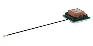
Antenna, 1.227GHz, GPS/Glonass/Galileo/BeiDou/IRNSS/GNSS, 3dB, Adhesive/I-Pex MHF Connector
- Manufacturer: PULSE ELECTRONICS
- Product type:
- Gain: 3dB
- SVHC: No SVHC (04-Feb-2026)
- VSWR: -
- Input Power: -
- Antenna Type: GPS / Glonass / Galileo / BeiDou / IRNSS / GNSS
- Frequency Max: 1.227GHz
- Frequency Min: -
- Product Range: -
- Input Impedance: 50ohm
- Antenna Mounting: Adhesive / I-Pex MHF Connector
- Antenna Polarisation: Right Hand Circular
| Delivery and price | |
|---|---|
| Units per pack | 50 |
| Price | 13.11 € |
| Current stock | 50+ |
| Lead time | 30 days |
GNSS Active Patch Antenna _GNSSL1L2182530_

## (oye

_Features:_ :

_Ultra low noise 30dB amplifiers_

   - _Stacked L1 / L2 patch antenna Single RF input with DC bias_

- _High rejection filters to suppress out of band interference ESD Protected For 15dB version use P/N: GNSSL1L2182515_

- _[>]

_Applications:_

- @ _GPS, Glonass, Galileo, Beidou, IRNSS_ @ _Multiband satellite navigation receivers_ @ _L1 and L2 band devices_

||**Electrical specifications1**<br>**@ 25° C**|**Electrical specifications1**<br>**@ 25° C**|**Electrical specifications1**<br>**@ 25° C**||
|---|---|---|---|---|
|**Antenna type **<br>**Nominal Impedance**||**Polarization**||**Radiationpattern**|
|Patch<br>50Ω||RHCP||Directional|
||||||
|**Frequency (MHz)**|L1: 1561-1602|||L2: 1227|
|**Return Loss(dB)**||< -10||< -9|
|**Radiating Element Peak Gain(dBi)**||>4||>3|
|**Radiating Element Peak Gain(dBic)**||>4||>0|
|**Avg. Efficiency (%)**||>80||>60|
|**LNA Gain(dB) Typical**||28||32|
|**Noise Figure(dB)**|1.7@1575MHz|||1.8@1227MHz|
|**Operating Voltage2 (VDC)**||2.5 - 18|||
|**Current Consumption(mA)**||Max. 16|||


## **Mechanical Specifications**

|**Mechanical Specificationspecificationsecifications**|**Mechanical Specificationspecificationsecifications**|**Mechanical Specificationspecificationsecifications**|**Mechanical Specificationspecificationsecifications**|**Mechanical Specificationspecificationsecifications**|
|---|---|---|---|---|
||||||
|**Dimension**<br>Length x Width x Height(w/o cable)|**Fixing method**|**Antenna Material**|**Connector**<br>**Type **|**Cable**<br>**Type **|
|30mm*30mm*13.09mm /<br>1.181”x1.181”x.515”|Adhesive<br>3M RP16|Ceramic+PCBA+cable|I-PEX MHF|Ø1.13mm|
|**Cable Length**|**Weight**|**RoHS- Compliant**|**Storage and operating**<br>**Temperature**||
|100mm/3.937”|12grams|Yes|-40°C to 85°C||


Notes:

1. The product is ESD sensitive, must be handled carefully and strictly according to the ESD requirements. 2. LNA internal voltage stabilized by LDO (Low dropout regulator)

> PulseElectronics.com Issue: 2315 1 ~~—VO~~

GNSS Active Patch Antenna _GNSSL1L2182530_

## Mechanical Drawing

All dimensions are in mm / inches

PulseElectronics.com

Issue: 2315

2

GNSS Active Patch Antenna _GNSSL1L2182530_

## Testing Setup

**==> picture [259 x 13] intentionally omitted <==**

**----- Start of picture text -----**<br>
Module is tested on 80*80mm ground plane.<br>**----- End of picture text -----**<br>


## Active Antenna Block Diagram

**==> picture [134 x 13] intentionally omitted <==**

**----- Start of picture text -----**<br>
PulseElectronics.com<br>3<br>**----- End of picture text -----**<br>


Issue: 2315

GNSS Active Patch Antenna _GNSSL1L2182530_

## Return Loss

**==> picture [411 x 224] intentionally omitted <==**

**----- Start of picture text -----**<br>
0 S11<br>-5<br>mt ft _<br>m1: 1.575 GHz<br>-13.37 dB<br>-10<br>Reumnmnea m2 m1 m2: 1.227 GHz<br>-13.61 dB<br>-15<br>ef\<br>EN<br>-20<br>|<br>-25 ante<br>-30<br>0.6 0.8 1 1.2 1.4 1.6 1.8 2<br>Frequency (GHz)<br>(dB)<br>**----- End of picture text -----**<br>


## LNA Out of band rejection

**==> picture [345 x 279] intentionally omitted <==**

**----- Start of picture text -----**<br>
40<br>m2 L2<br>m1<br>30<br>L1<br>20 eT]CINECCCECE<br>10 IMCLCIC L ECC- |<br>0<br>C EC CCEEE<br>-10 IWC E EE<br>-20 INCE CECE CLA m8<br>m4<br>-30 nN m5 m7<br>-40 0 a m6 areca<br>-50 m3 SEAT ima” SST InN<br>di<br>-60 a |<br>0.5 1 1.5 2 2.5 3 3.5 4 4.5 5 5.5 6 6.5 7 7.5 8 8.5<br>Frequency (GHz)<br>m2: 1.227 GHz m1: 1.575 GHz m3: 0.617 GHz m4: 0.96 GHz<br>31.64 dB 28.39 dB -54.90 dB -31.05 dB<br>m5: 1.71 GHz m6: 2.7 GHz m7: 4.5 GHz m8: 7.15 GHz<br>-36.76 dB -47.20 dB -35.52 dB -24.41 dB<br>Gain (dB)<br>**----- End of picture text -----**<br>


> PulseElectronics.com Issue: 2315 4 J ~~we~~

GNSS Active Patch Antenna _GNSSL1L2182530_

## LNA Gain

**==> picture [529 x 285] intentionally omitted <==**

**----- Start of picture text -----**<br>
_ S21 —s23<br>L1 GNSSL1L2 L2 GNSSL1L2<br>40 m1: 1.575 GHz<br>30 [| | | | | m2 et m1 m3 | ft | tl 28.76 dB ° . | [| |imt: 4.227 Gre<br>20 m2: 1.561 GHz<br>29.13 dB<br>10 | | | | f | | y | ft !<br>0 | | | tet ft | yt m3: 1.602 GHz28.12 dB a, a|<br>-10<br>-20 Ft ft iN | | TT WA 5<br>-30 ee ee vy | tT Ty TV<br>-40 Ae ee ee ‘<br>-50 FG al | .<br>1.45 1.475 1.5 1.525 1.55 1.575 1.6 1.625 1.65 1.675 1.7 11 1.125 1.15 1.175 1.2 1.225 1.25 1.275 1.3<br>Frequency (GHz) Frequency (GHz)<br>S21 S23<br>L1 GNSSL1L2 L2 GNSSL1L2<br>40 40 m1<br>m1 m1: 1.575 GHz m1: 1.227 GHz<br>20 28.76 dB 20 32.52 dB<br>0 m2: 1.227 GHz 0 m2: 1.575 GHz<br>-19.19 dB -17.66 dB<br>m2 m2<br>-20 -20 m4<br>m5 m3: 0.617 GHz m3: 0.617 GHz<br>-40 m4 -60.90 dB -40 m5 -61.48 dB<br>ENE baa 7 ee a eee<br>-60 m3 wand) Ww m4: 0.96 GHz -60 m3 wa | m4: 0.96 GHz<br>-44.66 dB -29.55 dB<br>-80 -80<br>0.6 0.8 1 1.2 1.4 1.6 1.8 2 m5: 1.71 GHz 0.6 0.8 1 1.2 1.4 1.6 1.8 2 m5: 1.71 GHz<br>Frequency (GHz) -34.12 dB Frequency (GHz) -39.04 dB<br>Gain (dB)<br>Gain (dB)<br>Gain (dB)<br>**----- End of picture text -----**<br>


## LNA Noise Figure

## L1 Noise Figure

## L2 Noise Figure

PulseElectronics.com

Issue: 2315

5

## GNSS Active Patch Antenna _GNSSL1L2182530_

## Radiating Element Efficiency

**==> picture [557 x 14] intentionally omitted <==**

**----- Start of picture text -----**<br>
z =<br>z“ Need update    =<br>**----- End of picture text -----**<br>


## L1 Band

## L2 Band

## Radiating Element Peak Gain (Linear)

## L1 Band

## L2 Band

PulseElectronics.com

Issue: 2315

6

GNSS Active Patch Antenna _GNSSL1L2182530_

## Radiation Patterns RHCP (dBic)

## L1 RHCP Pattern @1575 MHz

L2 RHCP Pattern @1227 MHz

L2 3D RHCP Pattern @1227 MHz

PulseElectronics.com

Issue: 2315

7

GNSS Active Patch Antenna

_GNSSL1L2182530_

## Reliability Tests

|Temperature change|-40℃to +85 °C, MIL-STD 810G Method 503.5.<br>1.Room Temperature to -40 °C (2hours) 2.Storage for 2 hours at -40 °C  3.<br>-40 °C to 85 °C (2hours) 4. Storage for 2 hours at 85  °C 5. 85 °C to -40 °C<br>( 2hours) 6.Repeat from 2 to 5 for 5 times 7. -40 °C increase to room<br>temperature within 2 hours (Total 44 Hrs)<br>No loss of function after tests.|
|---|---|
|Storage test|-40°C to +85°C, MIL STD 810G Method 501.5 (high) Method 502.5 (low)<br>1.Room Temperature to -40°C within 2 hours  2.Storage for 24 hours at -<br>40°C; 3. -40°C to room temperature within 2 hours 4.Room Temperature<br>to +85°C within 2 hours 5.Storage for 24 hours at 85°C; 6. 85°C room<br>temperature within 2 hours(Total 56 Hrs)                                          No loss<br>of function after tests.|
|Shock test|1.Three shocks in each direction shall be applied along the three mutually<br>perpendicular axes of the test specimen (18 shocks) 2.Peak value:<br>1,500g’s 3.Duration: 0.5ms 4.Waveform: Half si. No loss of function after<br>tests.|
|Drop test|Drop test (single device) for mounted device, the antenna needs to be<br>fixed to PCB and then assemble PCBA into the covers for the test, please<br>do the test with Armadillo antenna, only need the PCB and top/bottom<br>cover for the tests.|
|Vibration test|Random vibration input of 60 min/axis, all three perpendicular axis.<br>Transportation frequency 5-500 Hz using Fig 514.6C-I and Table 514.6-II of<br>MIL STD 810G section 514.6, performed only upon customer request., no<br>loss of function after tests.|
|ESD Test|According to IEC/EN 61000-4-2 Electromagnetic compatibility<br>Test voltage ±2KV, voltage polarity: + and -  Discharge times: 3 times per<br>polarity,discharge frequency: 1 time/second|


## Package

## **Antennas packed in tray (ESD requirements according to DIN EN 61340-5.1)  and carton box**

Each antenna wrapped in foam bag 240 PCS/ carton box

Carton box dimensions (MM) : 405x300x180

For More Information:

> Americas -  antennas.us@pulseelectronics.com | Europe – antennas.eu@pulseelectronics.com | Asia – antennas.as@pulseelectronics.com | Questions? +1-800-ANTENNA Performance warranty of products offered on this data sheet is limited to the parameters specified. Data is subject to change without notice. Other brand and product names mentioned herein may be trademarks or registered trademarks of their respective owners. © Copyright , 2020. Pulse Electronics, Inc. All rights reserved. Company address: Pulse Electronics, a YAGEO Company, 15255 Innovation Drive, Suite #100, San Diego, CA 92128

aS

PulseElectronics.com

Issue: 2315

8
Updated at June 9, 2026
Pulse Electronics, a YAGEO company, is a global leader in the design and manufacturing of passive electronic components. With a legacy of innovation dating back to 1956, the company provides essential technology for the communications, computing, industrial, transportation, and IoT sectors. Pulse is recognized worldwide for delivering high-performance solutions that power advanced applications, ranging from 5G networks and electric vehicles to data centers and smart grids. The company's extensive product portfolio is heavily anchored in power and networking magnetics. This includes a comprehensive range of power inductors engineered for exceptional efficiency and reliability in demanding environments. To address complex electromagnetic compatibility challenges, Pulse also manufactures highly effective EMC and RFI suppression solutions, such as common mode chokes and filters, alongside specialized toroidal and RF inductors designed to ensure clean power delivery and optimal signal integrity. Beyond traditional magnetics, Pulse excels in the development of advanced wireless and power conversion components. Their connectivity solutions feature a wide array of high-performance RF antennas and single-band chip antennas tailored for modern connected devices. Furthermore, to support sophisticated power architectures, Pulse provides a broad spectrum of transformers—encompassing PCB-mounted designs, current sensing transformers, and precise pulse transformers—equipping engineers with robust, industry-proven components for power isolation and measurement.
About Novapart
Novapart is a B2B electronic component broker specialising in stock shortages and cost reduction. We source hard-to-find parts and identify compliant alternatives across a catalogue of 410,000+ components from 500+ manufacturers.
Learn more →Stock Shortage Specialist
When a component is unavailable, discontinued or has an unacceptable lead time, we tap into our network of vetted European and Asian distributors to source what you need — without compromising on quality or traceability.
Request a quote →Compliant Alternatives
We identify pin-to-pin, electrically equivalent substitutes that meet the same certifications (RoHS, AEC-Q100, REACH) as your original specification — validated against datasheets, not just part numbers. Often at a lower cost.
BOM Analysis service →