
Image not available
Illustrative purposes only

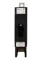
GHQ1015
CIRCUIT BREAKER, 1 POLE, 15A
⚠️ Reference pricing provided. In case of supply shortages, we will connect you with our trusted procurement partners to ensure your project's continuity.
- Manufacturer: EATON CUTLER HAMMER
- Product type: Thermal Magnetic Circuit Breakers
- No. of Poles: 1 Pole
- Product Range: GHQ Series
- Current Rating: 15A
- Voltage Rating VAC: 277VAC
- Circuit Breaker Mounting: DIN Rail, Panel
| Delivery and price | |
|---|---|
| Units per pack | 100 |
| Price | 84.88 € |
| Current stock | 10+ |
| Lead time | 7 days |
Datasheet

## **Product Guide 2011** Series C and = = . Special Application i = — ie Moulded Case Circuit Breakers *- pe es ot = aT = ™: al } ee ee # = all ; a - Series C and Special Application Moulded Case Circuit Breakers **==> picture [108 x 7] intentionally omitted <==** **----- Start of picture text -----**<br> Moulded Case Circuit Breaker Family<br>**----- End of picture text -----**<br> ## **Series C Moulded Case Circuit Breakers** **==> picture [336 x 238] intentionally omitted <==** **----- Start of picture text -----**<br> |||||| |---|---|---|---|---| |Description|Catalogue|Section| |Page No.|Page No.| |Product Line Overview . . . . . . . . . . . . . . . . . . . . . . . . . . . . . . .2|. . . . . . . . . .|1.2| |Product Line Description|. . . . . . . . . . . . . . . . . . . . . . . . . . . .2|. . . . . . . . . .|1.2| |Standards and Certifications|. . . . . . . . . . . . . . . . . . . . . . . . .2|. . . . . . . . . .|1.2| |Quick Reference|. . . . . . . . . . . . . . . . . . . . . . . . . . . . . . . . . .3|. . . . . . . . . .|1.3| |15 – 100 Amperes|. . . . . . . (G-Frame)|. . . . . . . . . . . . . . . . . . .6|. . . . . . . . . .|G-1| |10 – 225 Amperes|. . . . . . . (F-Frame)|. . . . . . . . . . . . . . . . . . .13|. . . . . . . . . .|F-1| |70 – 250 Amperes|. . . . . . . (J-Frame)|. . . . . . . . . . . . . . . . . . .21|. . . . . . . . . .|J-1| |70 – 400 Amperes|. . . . . . . (K-Frame)|. . . . . . . . . . . . . . . . . . .27|. . . . . . . . . .|K-1| |125 – 600 Amperes|. . . . . . . (L-Frame)|. . . . . . . . . . . . . . . . . . .41|. . . . . . . . . .|L-1| |300 - 800 Amperes|. . . . . . . (MDL-Frame)|. . . . . . . . . . . . . . . .53|. . . . . . . . . .|M-1| |400 – 1200 Amperes|. . . . . . (N-Frame)|. . . . . . . . . . . . . . . . . .61|. . . . . . . . . .|N-1| |800 – 2500 Amperes|. . . . . . (R-Frame)|. . . . . . . . . . . . . . . . . . .74|. . . . . . . . . .|R-1| |Motor Circuit Protectors|. . . . . . . . . . . . . . . . . . . . . . . . . . . . .93|. . . . . . . . . .|MCP-1| |Motor Protection Circuit Breakers . . . . . . . . . . . . . . . . . . . . . .101. . . . . . . . . . MPCB-1| |Earth Leakage Circuit Breakers . . . . . . . . . . . . . . . . . . . . . . .103|. . . . . . . . . .|ELCB-1| |Internal Accessories. . . . . . . . . . . . . . . . . . . . . . . . . . . . . . . .106|. . . . . . . . . .|INTA-1| |External Accessories . . . . . . . . . . . . . . . . . . . . . . . . . . . . . . .129|. . . . . . . . . .|EXTA-1| |Dimensions . . . . . . . . . . . . . . . . . . . . . . . . . . . . . . . . . . . . . .159|. . . . . . . . . .|DIM-1| **----- End of picture text -----**<br> ## **Special Application Moulded Case Circuit Breakers** **==> picture [337 x 70] intentionally omitted <==** **----- Start of picture text -----**<br> |||||| |---|---|---|---|---| |Current Limiting Circuit Protectors . . . . . . . . . . . . . . . . . . . .165|. . . . . . . . . .|CLCP-1| |Engine Generator Circuit Breakers|. . . . . . . . . . . . . . . . . . . .182|. . . . . . . . . .|EGCB-1| |Direct Current Circuit Breakers . . . . . . . . . . . . . . . . . . . . . . .186|. . . . . . . . . .|DCCB-1| |E|[2]|Mining Service Circuit Breakers . . . . . . . . . . . . . . . . . . . .199|. . . . . . . . . .|E2MB-1| |Classic Mining Service Circuit Breakers . . . . . . . . . . . . . . . .222|. . . . . . . . . .|CMCB-1| |Add-On Ground Fault Protection|. . . . . . .(GFR)|. . . . . . . . . .236|. . . . . . . . . .|GFR-1| **----- End of picture text -----**<br> **Series C and Special Application Moulded Case Circuit Breakers** PG01200001K—October 2011 www.eatoncanada.ca **1** Series C Moulded Case Circuit Breakers 1.2 ## Product Line Overview ## **Product Line Description** Eaton’s Moulded Case Circuit Breakers are designed to provide circuit protection for low voltage distribution systems. They are described by NEMA as, “a device for closing and interrupting a circuit between separable contacts under both normal and abnormal conditions,” and furthermore as, “a breaker assembled as an integral unit in a supporting and enclosing housing of insulating material.” The NEC describes them as, “A device designed to open and close a circuit by non-automatic means, and to open the circuit automatically on a predetermined overload of current, without injury to itself when properly applied within its rating.” So designed, Eaton circuit breakers protect conductors against overloads and conductors and connected apparatus, such as motors and motor starters, against short circuits. In low voltage distribution systems, there are many varied applications of moulded case circuit breakers. Eaton offers the most comprehensive family of moulded case circuit breakers in the industry. This section of circuit breakers includes: - G Thermal Magnetic Trip Breakers - G Electronic rms Trip Breakers - G Moulded Case Switches - G Motor Circuit Protectors - G Current Limiting Breakers G Special Application Breakers ## Eaton breakers can be ordered with internal accessories installed. These modified breakers will be subject to an additional charge. ## **Special Calibration** Special non-CSA/UL-listed calibrations are available for certain ambient temperatures other than 40°C and for frequencies other than 50/60 Hz or DC. Reduced interrupting ratings will apply for 400 Hz applications. Please refer to Eaton’s Consulting Application Guide, (CA08104001E) pages 28.2 - 16 for details. Suffix **H01** 400 Hz[� ] ## _**50°C Calibration**_ Add suffix **V** to Catalogue Number for complete breaker, when ordering listed ampere ratings for breakers to be used in 50°C ambients. ## Suffix **V** 50°C Calibration[�] ## **Moisture-Fungus Treatment** All circuit breaker cases are moulded from glass-polyester which does not support the growth of fungus. Any parts which are susceptible to the growth of fungus will require special treatment. Suffix **J01** Fungus Treated[�] ## **Freeze-Tested Circuit Breakers** The circuit breakers may be ordered with freeze testing. This option uses special lubrication and mechanical operation is verified at -40°C. Suffix **F01** Freeze Tested[�] ## **Marine Applications** F- to R-Frame circuit breakers can be supplied to meet the following marine specifications: - G U.S. Coast Guard CFR 46 ABS — American Bureau of Shipping IEEE 45; DNV; Lloyds; and ABS/NVR These specifications generally require moulded case circuit breakers to be supplied with special nameplating, and plug-in adapter kits. When plug-in adapter kits are used, no terminals need be supplied. Circuit breakers can also be supplied to meet UL489 Supplement SA (Marine Use) and UL489 Supplement SB (Naval Use). UL489 Supplement SA applies to vessels over 65 feet (19.8 m) in length. Requirements include 40°C ambient calibration, special labeling, and no use of aluminum conductors or terminals. **H08** “Marine” Or you can choose to add 50ºC ambient but then there is no “UL” mark. **VH08** “Marine” with 50ºC ambient calibration UL 489 Supplement SB requires partial 50ºC ambient calibration, vibration testings, special nameplating and no use of aluminum conductors or terminals. Eaton chooses to always fully calibrate to 50ºC ambient. (“Naval” labelled per UL and UL now allows 50°C label here). **VH09** “Naval” with 50ºC ambient calibration ## **Certified Test Reports** Eaton breakers can be ordered with certified test reports at the time of order entry for an additional charge. Test report documents the thermal and magnetic or electronic tripping characteristics of the individual breaker. Breaker and test reports must be ordered together. Add suffix 12 to breaker catalogue number and enter separate line item on order for certified test report. ## Moulded case circuit breakers are designed to conform with the following standards: - G Underwriters Laboratories, Inc., Standard UL489, Moulded Case Circuit Breakers and Circuit Breaker Enclosures - G National Electrical Manufacturers Association Standards Publication No. AB1-1993, Moulded Case Circuit Breakers - G Australian Standard AS 2184, Moulded Case Circuit Breakers - G British Standards Institution Standard BS 4752: Part 1, Switchgear and Control Gear Part 1: Circuit Breakers - G Canadian Standards Association Standard C22.2 No. 5, Moulded Case Circuit Breakers and Circuit Breaker Enclosures. - G International Electrotechnical Commission Recommendations IEC 60947-2, Circuit Breakers - G Japanese T-Mark Standard Moulded Case Circuit Breakers - G South African Bureau of Standards, Standard SABS 156, Standard Specification for Moulded Case Circuit Breakers - G Swiss Electro-Technical Association Standard SEV 157-1, Safety Regulations for Circuit Breakers - G Union Technique de l’Electricite Standard NF C 63-120, Low Voltage Switchgear and Control Gear Circuit Breaker Requirements - G Verband Deutscher Elektrotechniker (Association of German Electrical Engineers) Standard VDE 0660, Low Voltage Switchgear and Control Gear, Circuit Breakers Conformance with these standards satisfies most local and international codes, assuming user acceptability and simplified application. Moulded case circuit breakers equal or exceed Federal Specification Classification W-C-375b requirements for the particular class associated with the circuit breaker frame being considered. Open breakers do not have service entrance ratings. Service entrance rating is part of the enclosure. - Circuit breaker manufactured with this option will be supplied without the CSA/UL certification label. **Series C and Special Application Moulded Case Circuit Breakers** PG01200001K—October 2011 www.eatoncanada.ca **2** Series C Moulded Case Circuit Breakers 1.3 Product Line Overview ## **Quick Reference** ## **Industrial Circuit Breakers** |**Circuit**<br>**Breaker**<br>**Type**<br>**Cont.**<br>**Amp.**<br>**Rating**<br>**@ 40°C**<br>**No.**<br>**Poles**|**Volts**<br>**Type**<br>**of**<br>**Trip**�<br>**AC**<br>**DC**|**CSA/UL Listed Interrupting Ratings rms Symmetrical Amperes (kA)**<br>**Section**<br>**Page**<br>**Number**<br>**AC Ratings Volts**<br>**DC**�<br>**120**<br>**120/240 240**<br>**277**<br>**347**<br>**480Y/**<br>**277**<br>**480**<br>**600Y/**<br>**347**<br>**600**<br>**125**<br>**250**<br>**125/250**| |---|---|---| |**G-Frame**||| |GHQ<br>15 – 30<br>1|277<br>—<br>N.I.T.|—<br>—<br>—<br>14<br>—<br>—<br>—<br>—<br>—<br>—<br>—<br>—<br>**G-3**| |HGHB<br>15 – 30<br>1|277<br>125<br>N.I.T.|—<br>—<br>—<br>14<br>—<br>—<br>—<br>—<br>—<br>14<br>—<br>—<br>**G-3**| |GHB<br>GHB<br>15 – 100<br>15 – 100<br>1<br>2, 3|277<br>480Y/277<br>125<br>125/250<br>N.I.T.<br>N.I.T.|65<br>—<br>—<br>—<br>—<br>65<br>14<br>—<br>—<br>—<br>—<br>14<br>—<br>—<br>—<br>—<br>—<br>—<br>14<br>—<br>—<br>—<br>—<br>14<br>**G-3**<br>**G-3**| |GBH➂<br>GBH➂<br>15 – 100<br>15 – 100<br>1<br>2, 3|347<br>600Y/347<br>125<br>125/250<br>N.I.T.<br>N.I.T.|65<br>—<br>—<br>—<br>—<br>65<br>14<br>—<br>10<br>—<br>—<br>14<br>—<br>—<br>—<br>10<br>—<br>—<br>14<br>—<br>—<br>—<br>—<br>14<br>**G-3**<br>**G-3**| |HGHC<br>15 – 30<br>1|277<br>125<br>N.I.T.|—<br>—<br>—<br>14<br>—<br>—<br>—<br>—<br>—<br>14<br>—<br>—<br>**G-4**| |GHC<br>GHC<br>15 – 100<br>15 – 100<br>1<br>2, 3|277<br>480Y/277<br>125<br>125/250<br>N.I.T.<br>N.I.T.|65<br>—<br>—<br>—<br>—<br>65<br>14<br>—<br>—<br>—<br>—<br>14<br>—<br>—<br>—<br>—<br>—<br>—<br>14<br>—<br>—<br>—<br>—<br>14<br>**G-4,5**<br>**G-4,5**| |GCH➂<br>GCH➂<br>15 – 100<br>15 – 100<br>1<br>2, 3|347<br>600Y/347<br>125<br>125/250<br>N.I.T.<br>N.I.T.|65<br>—<br>—<br>—<br>—<br>65<br>14<br>—<br>10<br>—<br>—<br>14<br>—<br>—<br>—<br>10<br>—<br>—<br>14<br>—<br>—<br>—<br>—<br>14<br>**G-4**<br>**G-4**| |GD<br>GD<br>15 – 50<br>15 – 100<br>2<br>3|480<br>480<br>125/250<br>250<br>N.I.T.<br>N.I.T.|—<br>—<br>—<br>—<br>65<br>65<br>—<br>—<br>—<br>—<br>—<br>—<br>14<br>22<br>—<br>—<br>—<br>—<br>—<br>—<br>—<br>10<br>10<br>—<br>**G-2**<br>**G-2**| |GHBGFEP➃<br>GHCGFEP➃<br>15 – 60<br>15 – 60<br>1<br>1|277<br>277<br>—<br>—<br>N.I.T.<br>N.I.T.|—<br>—<br>—<br>—<br>—<br>—<br>14<br>14<br>—<br>—<br>—<br>—<br>—<br>—<br>—<br>—<br>—<br>—<br>—<br>—<br>—<br>—<br>—<br>—<br>**G-6**<br>**G-6**| |**F-Frame**||| |ED<br>EDH<br>EDC<br>100 – 225<br>100 – 225<br>100 – 225<br>2, 3<br>2, 3<br>2, 3|240<br>240<br>240<br>125<br>125<br>125<br>N.I.T.<br>N.I.T.<br>N.I.T.|—<br>—<br>—<br>—<br>—<br>—<br>65<br>100<br>200<br>—<br>—<br>—<br>—<br>—<br>—<br>—<br>—<br>—<br>—<br>—<br>—<br>—<br>—<br>—<br>—<br>—<br>—<br>10<br>10<br>10<br>—<br>—<br>—<br>—<br>—<br>—<br>**F-4**<br>**F-4**<br>**F-4**| |EHD<br>EHD<br>15 – 100<br>15 – 100<br>1<br>2, 3|277<br>480<br>125<br>250<br>N.I.T.<br>N.I.T.|—<br>—<br>—<br>—<br>—<br>18<br>14<br>—<br>—<br>—<br>—<br>—<br>—<br>14<br>—<br>—<br>—<br>—<br>10<br>—<br>—<br>10<br>—<br>—<br>**F-4**<br>**F-4**| |FDB➂<br>FDB�<br>FDB�<br>15 – 150<br>15 – 225<br>15 – 225<br>1<br>2, 3<br>4|347<br>600<br>600<br>125<br>250<br>250<br>N.I.T.<br>N.I.T.<br>N.I.T.|—<br>—<br>—<br>—<br>—<br>—<br>—<br>18<br>18<br>—<br>—<br>—<br>14<br>—<br>—<br>—<br>—<br>—<br>—<br>14<br>14<br>—<br>—<br>—<br>—<br>14<br>14<br>10<br>—<br>—<br>—<br>10<br>10<br>—<br>—<br>—<br>**F-4**<br>**F-4**<br>**F-4**| |FD<br>FD<br>FD<br>FDE<br>15 – 150<br>15 – 225<br>15 – 225<br>15 – 225<br>1<br>2, 3<br>4<br>3|347<br>600<br>600<br>600<br>125<br>250<br>250<br>—<br>N.I.T.<br>N.I.T.<br>N.I.T.<br>N.I.T.|—<br>—<br>—<br>—<br>—<br>—<br>—<br>—<br>—<br>65<br>65<br>65<br>35<br>—<br>—<br>—<br>18<br>—<br>—<br>—<br>—<br>—<br>—<br>—<br>—<br>35<br>35<br>35<br>—<br>—<br>—<br>—<br>—<br>18<br>18<br>18<br>10<br>—<br>—<br>—<br>—<br>10<br>10<br>—<br>—<br>—<br>—<br>—<br>**F-4**<br>**F-4**<br>**F-4**<br>**F-5**| |HFD<br>HFD<br>HFD<br>HFDE<br>15 – 30<br>15 – 225<br>15 – 225<br>15 – 225<br>1<br>2,3<br>4<br>3|347<br>600<br>600<br>600<br>125<br>250<br>250<br>—<br>N.I.T.<br>N.I.T.<br>N.I.T.<br>N.I.T.|—<br>—<br>—<br>—<br>—<br>—<br>—<br>—<br>—<br>100<br>100<br>100<br>65<br>—<br>—<br>—<br>25➂<br>—<br>—<br>—<br>—<br>—<br>—<br>—<br>—<br>65<br>65<br>65<br>—<br>—<br>—<br>—<br>—<br>25<br>25<br>25<br>10<br>—<br>—<br>—<br>—<br>22<br>22<br>—<br>—<br>—<br>—<br>—<br>**F-5**<br>**F-5**<br>**F-5**<br>**F-5**| |FDC�<br>FDC �<br>FDC�<br>FDCE�<br>15 – 30<br>15 – 225<br>15 – 225<br>15 – 225<br>1<br>2, 3<br>4<br>3|347<br>600<br>600<br>600<br>125<br>250<br>250<br>—<br>N.I.T.<br>N.I.T.<br>N.I.T.<br>N.I.T.|—<br>—<br>—<br>—<br>—<br>—<br>—<br>—<br>—<br>200<br>200<br>200<br>—<br>—<br>—<br>—<br>30➂<br>—<br>—<br>—<br>—<br>—<br>—<br>—<br>—<br>100<br>100<br>100<br>—<br>—<br>—<br>—<br>—<br>35<br>35<br>25<br>10➂<br>—<br>—<br>—<br>—<br>22<br>22<br>—<br>—<br>—<br>—<br>—<br>**F-5**<br>**F-5**<br>**F-5**<br>**F-5**| > � N.I.T. is non-interchangeable trip unit and I.T. is interchangeable trip unit. - Two-pole circuit breaker, or two poles of three-pole circuit breaker at 250V DC. - CSA listed only. Not UL listed. - UL listed only. Not CSA listed. > � Current limiting. - The 175A 200A and 225A 2, 3 and 4 pole FDB breakers are CSA listed only, not UL listed. **Series C and Special Application Moulded Case Circuit Breakers** PG01200001K—October 2011 www.eatoncanada.ca **3** Series C Moulded Case Circuit Breakers 1.4 Product Line Overview ## **Industrial Circuit Breakers (Continued)** |**Circuit**<br>**Breaker**<br>**Type**<br>**Cont.**<br>**Amp.**<br>**Rating**<br>**@ 40°C**<br>**No.**<br>**Poles**|**Volts**<br>**Type**<br>**of**<br>**Trip**�<br>**AC**<br>**DC**|**CSA/UL Listed Interrupting Ratings rms Symmetrical Amperes (kA)**<br>**Section**<br>**Page**<br>**Number**<br>**AC Ratings Volts**<br>**DC**�<br>**120**<br>**120/240**<br>**240**<br>**277**<br>**480**<br>**600**<br>**125**<br>**250**<br>**125/250**| |---|---|---| |**J-Frame**||| |JD<br>HJD<br>JDC➂<br>70 – 250<br>70 – 250<br>70 – 250<br>2, 3, 4<br>2, 3, 4<br>2, 3, 4|600<br>600<br>600<br>250<br>250<br>250<br>I.T.<br>I.T.<br>I.T.|—<br>—<br>—<br>—<br>—<br>—<br>65<br>100<br>200<br>—<br>—<br>—<br>35<br>65<br>100<br>18<br>25<br>35<br>—<br>—<br>—<br>10<br>22<br>22<br>—<br>—<br>—<br>**J-3**<br>**J-3**<br>**J-3**| |**K-Frame**||| |DK<br>250 – 400<br>2, 3|240<br>250<br>I.T.|—<br>—<br>65<br>—<br>—<br>—<br>—<br>10<br>—<br>**K-6**| |KD<br>CKD<br>HKD<br>CHKD<br>KDC➂<br>100 – 400<br>100 – 400<br>100 – 400<br>100 – 400<br>100 – 400<br>2, 3, 4<br>2, 3, 4<br>2, 3, 4<br>2, 3, 4<br>2, 3, 4|600<br>600<br>600<br>600<br>600<br>250<br>250<br>250<br>250<br>250<br>I.T.<br>I.T.<br>I.T.<br>I.T.<br>I.T.|—<br>—<br>—<br>—<br>—<br>—<br>—<br>—<br>—<br>—<br>65<br>65<br>100<br>100<br>200<br>—<br>—<br>—<br>—<br>—<br>35<br>35<br>65<br>65<br>100<br>25<br>25<br>35<br>35<br>65<br>—<br>—<br>—<br>—<br>—<br>10<br>10<br>22<br>22<br>22<br>—<br>—<br>—<br>—<br>—<br>**K-4,5,9,10**<br>**K-7,11,12**<br>**K-4,5,9,10**<br>**K7,11,12**<br>**K-4,5,9,10**| |**L-Frame**||| |LD<br>CLD<br>HLD<br>CHLD<br>LDC➂<br>CLDC➂<br>300 – 600<br>300 – 600<br>300 – 600<br>300 – 600<br>300 – 600<br>300 – 600<br>2, 3, 4<br>2, 3, 4<br>2, 3, 4<br>2, 3, 4<br>2, 3, 4<br>2, 3, 4|600<br>600<br>600<br>600<br>600<br>600<br>250<br>250<br>250<br>250<br>250<br>250<br>I.T.<br>I.T.<br>I.T.<br>I.T.<br>I.T.<br>I.T.|—<br>—<br>—<br>—<br>—<br>—<br>—<br>—<br>—<br>—<br>—<br>—<br>65<br>65<br>100<br>100<br>200<br>200<br>—<br>—<br>—<br>—<br>—<br>—<br>35<br>35<br>65<br>65<br>100<br>100<br>25<br>25<br>35<br>35<br>50<br>50<br>—<br>—<br>—<br>—<br>—<br>—<br>22<br>22<br>25<br>25<br>25<br>25<br>—<br>—<br>—<br>—<br>—<br>—<br>**L-4,5,7**<br>**L-5,9**<br>**L-4,5,7**<br>**L-5,9**<br>**L-4,5,8**<br>**L-5,10**| |**MDL-Frame**||| |MDL<br>CMDL<br>HMDL<br>CHMDL<br>300 – 800<br>300 – 800<br>300 – 800<br>300 – 800<br>2, 3<br>2, 3<br>2, 3<br>2, 3|600<br>600<br>600<br>600<br>250<br>250<br>250<br>250<br>I.T.<br>I.T.<br>I.T.<br>I.T.|—<br>—<br>—<br>—<br>—<br>—<br>—<br>—<br>65<br>65<br>100<br>100<br>—<br>—<br>—<br>—<br>50<br>50<br>65<br>65<br>25<br>25<br>35<br>35<br>—<br>—<br>—<br>—<br>22<br>22<br>25<br>25<br>—<br>—<br>—<br>—<br>**M-4,5**<br>**M-5**<br>**M-4,5**<br>**M-5**| |**N-Frame**||| |ND<br>CND<br>HND<br>CHND<br>NDC<br>CNDC<br>600 – 1200<br>600 – 1200<br>600 – 1200<br>600 – 1200<br>600 – 1200<br>600 – 1200<br>3, 4<br>3, 4<br>3, 4<br>3, 4<br>3, 4<br>3, 4|600<br>600<br>600<br>600<br>600<br>600<br>—<br>—<br>—<br>—<br>—<br>—<br>N.I.T.<br>N.I.T.<br>N.I.T.<br>N.I.T.<br>N.I.T.<br>N.I.T.|—<br>—<br>—<br>—<br>—<br>—<br>—<br>—<br>—<br>—<br>—<br>—<br>65<br>65<br>100<br>100<br>200<br>200<br>—<br>—<br>—<br>—<br>—<br>—<br>50<br>50<br>65<br>65<br>100<br>100<br>25<br>25<br>35<br>35<br>65<br>65<br>—<br>—<br>—<br>—<br>—<br>—<br>—<br>—<br>—<br>—<br>—<br>—<br>—<br>—<br>—<br>—<br>—<br>—<br>**N-4,10**<br>**N-7,11**<br>**N-5,10**<br>**N-8,11**<br>**N-6,10**<br>**N-9,11**| - N.I.T. is non-interchangeable trip unit and I.T. is interchangeable trip unit. > � Two-pole circuit breaker, or two poles of three-pole circuit breaker at 250V DC. > � Current limiting. **Series C and Special Application Moulded Case Circuit Breakers** PG01200001K—October 2011 www.eatoncanada.ca **4** Series C Moulded Case Circuit Breakers 1.5 Product Line Overview ## **Industrial Circuit Breakers (Continued)** |**Circuit**<br>**Breaker**<br>**Type**<br>**Cont.**<br>**Amp**<br>**Rating**<br>**@ 40°C**<br>**No.**<br>**Poles**|**Volts**<br>**Type**<br>**of**<br>**Trip**�<br>**AC**<br>**DC**|**CSA/UL Listed Interrupting Ratings rms Symmetrical Amperes (kA)**<br>**Section**<br>**Page**<br>**Number**<br>**AC Ratings Volts**<br>**DC**�<br>**120**<br>**120/240**<br>**240**<br>**277**<br>**480**<br>**600**<br>**125**<br>**250**<br>**125/250**| |---|---|---| |**R-Frame**||| |RD 1600<br>CRD 1600<br>RD 2000<br>CRD 2000<br>RD 2500<br>RDC 1600<br>CRDC 1600<br>RDC 2000<br>CRDC 2000<br>RDC 2500<br>800 – 1600<br>800 – 1600<br>1000 – 2000<br>1000 – 2000<br>1000 – 2500<br>800 – 1600<br>800 – 1600<br>1000 – 2000<br>1000 – 2000<br>1000 – 2500<br>3, 4<br>3, 4<br>3, 4<br>3, 4<br>3, 4<br>3, 4<br>3, 4<br>3, 4<br>3, 4<br>3, 4|600<br>600<br>600<br>600<br>600<br>600<br>600<br>600<br>600<br>600<br>—<br>—<br>—<br>—<br>—<br>—<br>—<br>—<br>—<br>—<br>N.I.T.<br>N.I.T.<br>N.I.T.<br>N.I.T.<br>N.I.T.<br>N.I.T.<br>N.I.T.<br>N.I.T.<br>N.I.T.<br>N.I.T.|—<br>—<br>—<br>—<br>—<br>—<br>—<br>—<br>—<br>—<br>—<br>—<br>—<br>—<br>—<br>—<br>—<br>—<br>—<br>—<br>125<br>125<br>125<br>125<br>125<br>200<br>200<br>200<br>200<br>200<br>—<br>—<br>—<br>—<br>—<br>—<br>—<br>—<br>—<br>—<br>65<br>65<br>65<br>65<br>65<br>100<br>100<br>100<br>100<br>100<br>50<br>50<br>50<br>50<br>50<br>65<br>65<br>65<br>65<br>65<br>—<br>—<br>—<br>—<br>—<br>—<br>—<br>—<br>—<br>—<br>—<br>—<br>—<br>—<br>—<br>—<br>—<br>—<br>—<br>—<br>—<br>—<br>—<br>—<br>—<br>—<br>—<br>—<br>—<br>—<br>**R-4,7,9,11,13,15**<br>**R-6,8,10,12,14,16**<br>**R-4,7,9,11,13,15**<br>**R-6,8,10,12,14,16**<br>**R-4,7,9,11,13,15**<br>**R-5,7,9,11,13,15**<br>**R-6,8,10,12,14,16**<br>**R-5,7,9,11,13,15**<br>**R-6,8,10,12,14,16**<br>**R-5,7,9,11,13,15**| |||| |**HMCP Motor Circuit Protectors**||**MCP-1**| |**Current Limit R Current Limiting Circuit Breakers — Non-Fused Type**||| |FCL<br>15 – 100<br>2, 3<br>480<br>—<br>N.I.T.<br>—<br>—<br>200<br>—<br>150<br>—<br>—<br>—<br>—<br>**CLCP-1**||| |LCL<br>125 – 400<br>2, 3<br>600<br>—<br>N.I.T.<br>—<br>—<br>200<br>—<br>200<br>100<br>—<br>—<br>—<br>**CLCP-2**||| |**Tri-Pac Current Limiting Circuit Breakers — Fused Type**||| |FB<br>15 – 100<br>2, 3<br>600<br>250<br>N.I.T.<br>—<br>—<br>200<br>—<br>200<br>200<br>—<br>—<br>100<br>**CLCP-4**||| |LA<br>70 – 400<br>2, 3<br>600<br>250<br>I.T.<br>—<br>—<br>200<br>—<br>200<br>200<br>—<br>—<br>100<br>**CLCP-5**||| |NB<br>300 – 800<br>2, 3<br>600<br>250<br>I.T.<br>—<br>—<br>200<br>—<br>200<br>200<br>—<br>—<br>100<br>**CLCP-7**||| |PB<br>600 – 1600<br>2, 3<br>600<br>250<br>I.T.<br>—<br>—<br>200<br>—<br>200<br>200<br>—<br>—<br>100<br>**CLCP-9**||| > � N.I.T. is non-interchangeable trip unit and I.T. is interchangeable trip unit. - Two-pole circuit breaker, or two poles of three-pole circuit breaker at 250V DC. **Series C and Special Application Moulded Case Circuit Breakers** PG01200001K—October 2011 www.eatoncanada.ca **5** 15-100 Amperes G-Frame ## G-1 ## Series C Moulded Case Circuit Breakers ## **Product Description** - **Series C Moulded Case Cir-** G All two- and three-pole circuit breakers are of the common trip type. On all 3- - **cuit Breakers** phase Delta (240V) Grounded B phase **15-100 Amperes** G applications, refer to Eaton.Single-pole circuit breakers, 15 and 20 **Series C Moulded Case Cir-** amperes. Switching duty rated (SWD) - **cuit Breakers** for fluorescent lighting applications. **15-100 Amperes** G All G-frame circuit breakers are suitable for reverse feed use. **Series C Moulded Case Cir-** G HACR rated. ## **Technical Data and Specifications** ## **CSA C22.2 No. 5 and UL489 Interrupting Capacity Ratings** |**Circuit Breaker**<br>**Type**<br>**Number**<br>**of Poles**|**Interrupting Capacity (Symmetrical Amperes) (kA)**<br>**Section**<br>**Page**<br>**Number**<br>**Volts Ac (50/60 Hz)**<br>**Volts Dc**<br>**120**<br>**240**<br>**277**<br>**480**<br>**125/**<br>**250**➁<br>**250**➀➁| |---|---| |GD<br>2<br>3|–<br>–<br>65<br>65<br>–<br>–<br>14<br>22<br>10<br>–<br>–<br>10<br>G-2| |**Circuit Breaker**<br>**Type**<br>**Number**<br>**of Poles**|**Interrupting Capacity (Symmetrical Amperes) (kA)**<br>**Section**<br>**Page**<br>**Number**<br>**Volts Ac (50/60 Hz)**<br>**Volts Dc**<br>**120**<br>**240**<br>**277**<br>**347**<br>**480Y/277 600Y/347 125**<br>**125/250**➀➁| |---|---| |GHQ<br>1|–<br>–<br>14<br>–<br>–<br>–<br>–<br>–<br>G-3| |HGHB<br>1|–<br>–<br>25<br>–<br>–<br>–<br>14<br>–<br>G-3| |GHB<br>1<br>2, 3|65<br>–<br>–<br>65<br>14<br>–<br>–<br>–<br>–<br>14<br>–<br>–<br>14➂<br>–<br>–<br>14<br>G-3<br>G-3| |GBH➃<br>1<br>2, 3|65<br>–<br>–<br>65<br>14<br>–<br>10<br>–<br>–<br>14<br>–<br>10<br>14➂<br>–<br>–<br>14<br>G-3<br>G-3| |HGHC<br>1|–<br>–<br>25<br>–<br>–<br>–<br>14<br>–<br>G-4| |GHC<br>1<br>2, 3|65<br>–<br>–<br>65<br>14<br>–<br>–<br>–<br>–<br>14<br>–<br>–<br>14➂<br>–<br>–<br>14<br>G-4<br>G-4| |GCH➃<br>1<br>2, 3|65<br>–<br>–<br>65<br>14<br>–<br>10<br>–<br>–<br>14<br>–<br>10<br>14➂<br>–<br>–<br>14<br>G-4<br>G-4| |GHBGFEP➄<br>1|–<br>–<br>14<br>–<br>–<br>–<br>–<br>–<br>G-6| |GHCGFEP➄<br>1|–<br>–<br>14<br>–<br>–<br>–<br>–<br>–<br>G-6| ## **Catalogue Numbering System** This information is presented only as an aid to understanding catalogue numbers. It is not to be used to build catalogue numbers for circuit breakers or trip units. ## **Circuit Breaker/Frame Catalogue Number** ## **GD 3 100** ||||||| |---|---|---|---|---|---| ||||||| |**Circuit**<br>**Breaker Type**||**Number of**<br>**poles**||**Trip**<br>**Amperes**|**Suffix**| ||||||K:<br>Moulded Case Switch<br>V:<br>50°C<br>F01: Freeze Tested<br>J01: Fungus Protected<br>R01: Shock Tested| |GD<br>GHB<br>GBH<br>GHC<br>GCH<br>GHQ<br>HGHB<br>HGHC||1: 1 Pole<br>2: 2 Pole<br>3: 3 Pole||15<br>20<br>24<br>30<br>35<br>40<br>45<br>50<br>60<br>70<br>80<br>90<br>100|| ||||||| ||||||| ||||||| ## **Terminal Types** |**Circuit**|**Terminal**|**Screw**||**AWG**|| |---|---|---|---|---|---| |**Breaker**<br>**Amperes**|**Type**<br>**Material**|**Head**<br>**Type**|**Wire**<br>**Type**|**Wire**<br>**Range**|**Metric Wire**�<br>**Range (mm2)**| |**Standard**|||||| |15-20|Clamp (Plated Steel)|Slotted|Cu/Al|#14-10|2.5-4| |25-100|Pressure (Aluminum Body)|Slotted|Cu/Al|#10-1/0|4-50| |**Optional -**|**GD Only**||||| |15-100|Pressure (Steel Body)|Slotted|Cu|#14 - #3|–| ## **Terminal Torque Values** |**AWG Wire**|**Torque**|**Torque**| |---|---|---| |**Range**|**Value bl-in**|**Value N.m.**| |#14-#10|20|2.26| |#8|40|4.52| |#6-#4|45|5.09| |#3-1/0|45|5.09| - Two poles of 3-pole circuit breaker. Two poles in series for 250 VDC application. - Time constant is 8 milliseconds minimum. - 15 through 70A breakers only. - CSA listed only, Not UL listed. - UL listed only, not CSA listed. - Not CSA and UL listed sizes. **Series C and Special Application Moulded Case Circuit Breakers** PG01200001K—October 2011 www.eatoncanada.ca 6 G-2 Series C Moulded Case Circuit Breakers 15-100 Amperes G-Frame ## **Type GD Thermal-Magnetic Circuit Breakers with Non-Interchangeable Trip Units** **==> picture [69 x 8] intentionally omitted <==** **----- Start of picture text -----**<br> Type GD Circuit Breaker<br>**----- End of picture text -----**<br> ## **Product Selection** **Type GD Thermal-Magnetic Circuit Breakers with Non-Interchangeable Trip-Units** ||**480 Vac Maximum, 250 Vdc**||| |---|---|---|---| ||**14 kAIC @ 480 Vac**|**22 kAIC @ 480 Vac**|| |**Maximum**|**10 kAIC @ 125/250 Vdc**➁|**10 kAIC @ 250 Vdc**➀➁|| |**Continuous**|||**Catalogue Number**| |**Ampere Rating**|**Catalogue Number**||**(Includes binding head screws**| |**@ 40°C**|**(Includes Line and Load Terminals)**||**and clamps 10-32 x .312)**| ||**2-Pole**|**3-Pole**|**3-Pole**| |15|**GD2015**|**GD3015**|**GD3015D**| |20|**GD2020**|**GD3020**|**GD3020D**| |25|**GD2025**|**GD3025**|**GD3025D**| |30|**GD2030**|**GD3030**|**GD3030D**| |35|**GD2035**|**GD3035**|**GD3035D**| |40|**GD2040**|**GD3040**|**GD3040D**| |45|**GD2045**|**GD3045**|**GD3045D**| |50|**GD2050**|**GD3050**|**GD3050D**| |60|**-**|**GD3060**|**GD3060D**| |70|**-**|**GD3070**|**GD3070D**| |80|**-**|**GD3080**|**GD3080D**| |90|**-**|**GD3090**|**GD3090D**| |100|**-**|**GD3100**|**GD3100D**| Instruction Leaflet Number 29C102 ## I UL/CSA. ## **Type GD Moulded Case Switches** ## **Product Description** - I Cable in, cable out. - I Includes mounting hardware and BMHE. |**Maximum**|**480 Vac Maximum, 250 Vdc**| |---|---| |**Continuous**|| |**Ampere Rating**|| |**@ 40°C**|**Catalogue Number (Includes Line and Load Terminals)**| |**3-Pole**|| |60|**GD3060K**| |100|**GD3100K**| |60|**GD3060KC**➂| |60|**GD3060KD**➃| |100|**GD3100KD**➃| **Note:** Moulded Case Switches may open above 1300A Instruction Leaflet Number 29C102 Two poles of 3-pole circuit breaker. Two poles in series for 250 VDC application. Time constant is 8 milliseconds minimum. Includes line and load steel terminals. > Includes binding head screws. **Series C and Special Application Moulded Case Circuit Breakers** PG01200001K—October 2011 www.eatoncanada.ca **7** G-3 ## Series C Moulded Case Circuit Breakers ## 15-100 Amperes G-Frame ## **Types GHB, GBH, GHQ and HGHB Bolt-On Panelboard Circuit Breakers** Type GHB, 277 and 480Y/277V Type GBH, 347 and 600Y/347V Type GHQ, 277V Type HGHB, 277V **==> picture [35 x 8] intentionally omitted <==** **----- Start of picture text -----**<br> Typical GBH<br>**----- End of picture text -----**<br> ## **Type GHB Thermal-Magnetic Circuit Breakers with Non-Interchangeable Trip Units** ||**277 Vac Maximum,**|**480Y/277 Vac Maximum,**|**480Y/277 Vac Maximum,**| |---|---|---|---| ||**125 Vdc Maximum**➀|**125/250 Vdc Maximum**|**125/250 Vdc Maximum**➁| |**Continuous**|**1-Pole**|**2-Pole**|**3-Pole**| |**Ampere Rating**|||| |**@ 40°C**|**Catalogue Number**||| |15|**GHB1015**➂|**GHB2015**➂|**GHB3015**➂| |20|**GHB1020**➂|**GHB2020**➂|**GHB3020**➂| |25|**GHB1025**|**GHB2025**|**GHB3025**| |30|**GHB1030**|**GHB2030**|**GHB3030**| |35|**GHB1035**|**GHB2035**|**GHB3035**| |40|**GHB1040**|**GHB2040**|**GHB3040**| |45|**GHB1045**|**GHB2045**|**GHB3045**| |50|**GHB1050**|**GHB2050**|**GHB3050**| |60|**GHB1060**|**GHB2060**|**GHB3060**| |70|**GHB1070**|**GHB2070**|**GHB3070**| |80|**GHB1080**|**GHB2080**|**GHB3080**| |90|**GHB1090**|**GHB2090**|**GHB3090**| |100|**GHB1100**|**GHB2100**|**GHB3100**| |**Type GBH Thermal-Magnetic Circuit Breakers with Non-Interchangeable Trip Units**||**Type GBH Thermal-Magnetic Circuit Breakers with Non-Interchangeable Trip Units**<br>®|| ||**347 Vac Maximum,**|**600Y/347 Vac Maximum,**|**600Y/347 Vac Maximum,**| ||**125 Vdc Maximum**➀|**125/250 Vdc Maximum**|**125/250 Vdc Maximum**➁| |**Continuous**|**1-Pole**|**2-Pole**|**3-Pole**| |**Ampere Rating**|||| |**@ 40°C**|**Catalogue Number**||| |15|**GBH1015**➂|**GBH2015**➂|**GBH3015**➂| |20|**GBH1020**➂|**GBH2020**➂|**GBH3020**➂| |25|**GBH1025**|**GBH2025**|**GBH3025**| |30|**GBH1030**|**GBH2030**|**GBH3030**| |35|**GBH1035**|**GBH2035**|**GBH3035**| |40|**GBH1040**|**GBH2040**|**GBH3040**| |45|**GBH1045**|**GBH2045**|**GBH3045**| |50|**GBH1050**|**GBH2050**|**GBH3050**| |60|**GBH1060**|**GBH2060**|**GBH3060**| |70|**GBH1070**|**GBH2070**|**GBH3070**| |80|**GBH1080**|**GBH2080**|**GBH3080**| |90|**GBH1090**|**GBH2090**|**GBH3090**| |100|**GBH1100**|**GBH2100**|**GBH3100**| Instruction Leaflet Number 15547. ## **Type GHQ Thermal-Magnetic Circuit Breakers with Non-Interchangeable Trip Units** ||**277V AC Maximum 14 KAIC, No DC Rating (HID & SWD)**| |---|---| |**Continuous**|**1-Pole**| |**Ampere Rating**|| |**@ 40°C**|**Catalogue Number**| |15|**GHQ1015**| |20|**GHQ1020**| ## **Type HGHB Thermal-Magnetic Circuit Breakers with Non-Interchangeable Trip Units** ||**277V AC Maximum, 125V DC Maximum**| |---|---| |**Continuous**|**1-Pole**| |**Ampere Rating**|| |**@ 40°C**|**Catalogue Number**| |15|**HGHB1015**| |20|**HGHB1020**| |25|**HGHB1025**| |30|**HGHB1030**| 15 through 70 ampere circuit breakers only. Use (2) outside poles. Two poles in series for 250VDC application. > Uses .190-32 screw type clamp terminals. > 480Y/277V, circuit breakers (Type GHB) not suitable for 3-phase Delta (480V). 600Y/347V, circuit breakers (Type GBH) not suitable for 3-phase Delta (600V). CSA listed only. Not UL listed **Series C and Special Application Moulded Case Circuit Breakers** PG01200001K—October 2011 www.eatoncanada.ca 8 G-4 Series C Moulded Case Circuit Breakers 15-100 Amperes G-Frame **1** ## **Types GHC, GCH and HGCH Circuit Breakers** Type CHC, 277 and 480Y/277V Type GCH, 347 and 600Y/347V Type HGHC, 277V ## **Typical GCH** ## **Type GHC Thermal-Magnetic Circuit Breakers with Non-Interchangeable Trip Units** ® ||**277 Vac Maximum,**|**480Y/277 Vac Maximum,**|**480Y/277 Vac Maximum,**| |---|---|---|---| |**Continuous**<br>**Ampere Rating**<br>**@ 40°C**|**125 Vdc Maximum**➀<br>**1-Pole**<br>**Catalogue Number**|**125/250 Vdc Maximum**<br>**2-Pole**|**125/250 Vdc Maximum**➁<br>**3-Pole**| |15<br>20|**GHC1015**➂<br>**GHC1020**➂|**GHC2015**➂<br>**GHC2020**➂|**GHC3015**➂<br>**GHC3020**➂| |25|**GHC1025**|**GHC2025**|**GHC3025**| |30<br>35|**GHC1030**<br>**GHC1035**|**GHC2030**<br>**GHC2035**|**GHC3030**<br>**GHC3035**| |40<br>45|**GHC1040**<br>**GHC1045**|**GHC2040**<br>**GHC2045**|**GHC3040**<br>**GHC3045**| |50|**GHC1050**|**GHC2050**|**GHC3050**| |60<br>70|**GHC1060**<br>**GHC1070**|**GHC2060**<br>**GHC2070**|**GHC3060**<br>**GHC3070**| |80|**GHC1080**|**GHC2080**|**GHC3080**| |90<br>100|**GHC1090**<br>**GHC1100**|**GHC2090**<br>**GHC2100**|**GHC3090**<br>**GHC3100**| ## y[e] **Type GCH Thermal-Magnetic Circuit Breakers with Non-Interchangeable Trip Units** |**347 Vac Maximum,**<br>**125 Vdc Maximum**➀<br>**600Y/347 Vac Maximum,**<br>**125/250 Vdc Maximum**<br>**600Y/347 Vac Maximum,**<br>**125/250 Vdc Maximum**➁<br>~~|~~|**347 Vac Maximum,**<br>**125 Vdc Maximum**➀<br>**600Y/347 Vac Maximum,**<br>**125/250 Vdc Maximum**<br>**600Y/347 Vac Maximum,**<br>**125/250 Vdc Maximum**➁<br>~~|~~|**347 Vac Maximum,**<br>**125 Vdc Maximum**➀<br>**600Y/347 Vac Maximum,**<br>**125/250 Vdc Maximum**<br>**600Y/347 Vac Maximum,**<br>**125/250 Vdc Maximum**➁<br>~~|~~|**347 Vac Maximum,**<br>**125 Vdc Maximum**➀<br>**600Y/347 Vac Maximum,**<br>**125/250 Vdc Maximum**<br>**600Y/347 Vac Maximum,**<br>**125/250 Vdc Maximum**➁<br>~~|~~| |---|---|---|---| |**Continuous**<br>**Ampere Rating**|**1-Pole**|**2-Pole**|**3-Pole**| |**@ 40°C**|**Catalogue Number**||| |15|**GCH1015**➂|**GCH2015**➂|**GCH3015**➂| |20|**GCH1020**➂|**GCH2020**➂|**GCH3020**➂| |25<br>30|**GCH1025**<br>**GCH1030**|**GCH2025**<br>**GCH2030**|**GCH3025**<br>**GCH3030**| |35<br>40|**GCH1035**<br>**GCH1040**|**GCH2035**<br>**GCH2040**|**GCH3035**<br>**GCH3040**| |45|**GCH1045**|**GCH2045**|**GCH3045**| |50<br>60|**GCH1050**<br>**GCH1060**|**GCH2050**<br>**GCH2060**|**GCH3050**<br>**GCH3060**| |70|**GCH1070**|**GCH2070**|**GCH3070**| |80<br>90|**GCH1080**<br>**GCH1090**|**GCH2080**<br>**GCH2090**|**GCH3080**<br>**GCH3090**| |100|**GCH1100**|**GCH2100**|**GCH3100**| Instruction Leaflet Number 15548. ## **Type HGHC Thermal-Magnetic Circuit Breakers with Non-Interchangeable Trip Units** ||**277V AC Maximum, 125V DC Maximum**| |---|---| |**Continuous**|**1-Pole**| |**Ampere Rating**|| |**@ 40°C**|**Catalogue Number**| |15|**HGHC1015**| |20|**HGHC1020**| |25|**HGHC1025**| |30|**HGHC1030**| 15 through 70 ampere circuit breakers only. Use (2) outside poles. Two poles in series for 250VDC application. > Uses .190-32 screw type clamp terminals. > 480Y/277V, circuit breakers (Type GHC) not suitable for 3-phase Delta (480V). > 600Y/347V, circuit breakers (Type GCH) not suitable for 3-phase Delta (600V). CSA listed only. Not UL listed. **Series C and Special Application Moulded Case Circuit Breakers** PG01200001K—October 2011 www.eatoncanada.ca **9** G-5 Series C Moulded Case Circuit Breakers 15-100 Amperes G-Frame ## **Special Purpose GHC Circuit Breakers** This is Type GHC circuit breaker with binding head screw-type terminals on line and load side. This circuit breaker with screw-type terminals (.190-32) will be marked “Special purpose breaker not for general use.” To order this special breaker, use the catalogue number below. ## **Type GHC Thermal-Magnetic Circuit Breakers with Non-Interchangeable Trip Units** |**Units**|| |---|---| |**Continuous**<br>**Ampere Rating**<br>**@ 40°C**|**277 Vac Maximum,**<br>**125 Vdc Maximum**<br>**480Y/277 Vac Maximum,**<br>**125/250 Vdc Maximum**<br>**480Y/277 Vac Maximum,**<br>**125/250 Vdc Maximum**➀| ||**1-Pole**<br>**2-Pole**<br>**3-Pole**| ||**Catalogue Number**| |25<br>30<br>35<br>40<br>45<br>50<br>55<br>60<br>70<br>80<br>90<br>100|**GHC1025D**<br>**GHC1030D**<br>**GHC1035D**<br>**GHC1040D**<br>**GHC1045D**<br>**GHC1050D**<br>**GHC1055D**<br>**GHC1060D**<br>**GHC1070D**<br>**GHC1080D**<br>**GHC1090D**<br>**GHC1100D**<br>**GHC2025D**<br>**GHC2030D**<br>**GHC2035D**<br>**GHC2040D**<br>**GHC2045D**<br>**GHC2050D**<br>**GHC2055D**<br>**GHC2060D**<br>**GHC2070D**<br>**GHC2080D**<br>**GHC2090D**<br>**GHC2100D**<br>**GHC3025D**<br>**GHC3030D**<br>**GHC3035D**<br>**GHC3040D**<br>**GHC3045D**<br>**GHC3050D**<br>**GHC3055D**<br>**GHC3060D**<br>**GHC3070D**<br>**GHC3080D**<br>**GHC3090D**<br>**GHC3100D**| Instruction Leaflet Number 15548 ## **Type GHB and GHC Thermal-Magnetic Circuit Breakers with Non-interchangeable Trip Units for HID Lighting Applications** |||**277 Vac Maximum**| |---|---|---| ||**Continuous**|**1-Pole**| |**Type**|**Ampere Rating@ 40°C**|**Catalogue Number**| |Cable-In|15|**GHC1015HID**| ||20|**GHC1020HID**| |Bolt-On|15|**GHB1015HID**| ||20|**GHB1020HID**| Instruction Leaflet Number 15547 for Bolt-On type; 15548 for Cable-In type. > � Use (2) outside poles. Two pole in series for 250VDC application. **Series C and Special Application Moulded Case Circuit Breakers** PG01200001K—October 2011 www.eatoncanada.ca **10** G-6 Series C Moulded Case Circuit Breakers 15-100 Amperes G-Frame ## **Types GHBGFEP Bolt-on Panelboard 30mA Industrial Ground Fault Circuit Protectors** ## **15-60 Amperes, 277 Volt AC, 50/60 Hz** **==> picture [114 x 8] intentionally omitted <==** **----- Start of picture text -----**<br> Single Phase (Requires 2 Poles Spaces)<br>**----- End of picture text -----**<br> These circuit breakers meet the requirements of UL489 and UL1053. Operational voltage 240V to 305V. ## **Interrupting Capacity Ratings** |**Circuit**<br>**Breaker**|**Number**<br>**of Poles**|**Interrupting Capacity**<br>**(Symmetrical Amperes)**| |---|---|---| |**Type**||**277 Volts Ac (50/60 Hz)**| |GHBGFEP|1|14,000| **Type GHBGFEP Bolt-on Panelboard 30mA Industrial Ground Fault Circuit Protectors with Non-Interchangeable Trip Units** |**Trip Units**|| |---|---| |**Continuous**|**One Phase (Requires 2 Poles)**| |**Ampere**|**277 Vac, 30mA**| |**Rating**|| |**@40oC**|**Catalogue Number**| |15|**GHBGFEP1015**| |20|**GHBGFEP1020**| |30|**GHBGFEP1030**| |40|**GHBGFEP1040**| |50|**GHBGFEP1050**| |60|**GHBGFEP1060**| Instruction Leaflet Number 29C193 ## **Types GHCGFEP Cable In/Cable Out 30mA Industrial Ground Fault Circuit Protectors** ## **15-60 Amperes, 277 Volt AC, 50/60 Hz** **==> picture [113 x 7] intentionally omitted <==** **----- Start of picture text -----**<br> Single Phase (Requires 2 Poles Spaces)<br>**----- End of picture text -----**<br> **Type GHCGFEP Cable In/Cable Out 30mA Industrial Ground Fault Circuit Protectors with Non-Interchangeable Trip Units** These circuit breakers meet the requirements of UL489 and UL 1053. |UL 1053.|**with Non-Interchangeable Trip Units**| |---|---| |Operational voltage 240V to 305V.|**Continuous**<br>**Ampere**<br>**Rating**<br>**@40oC**<br>**One Phase (Requires 2 Poles)**<br>**277 Vac, 30mA**<br>**Catalogue Number**| |**Interrupting Capacity Ratings**<br>**Circuit**<br>**Breaker**<br>**Type**<br>**Number**<br>**of Poles**<br>**Interrupting Capacity**<br>**(Symmetrical Amperes)**<br>**277 Volts Ac (50/60 Hz)**<br>GHCGFEP<br>1<br>14,000|15<br>20<br>30<br>40<br>50<br>60<br>**GHCGFEP1015**<br>**GHCGFEP1020**<br>**GHCGFEP1030**<br>**GHCGFEP1040**<br>**GHCGFEP1050**<br>**GHCGFEP1060**<br>Instruction Leaflet Number 29C193<br>~~a~~<br>~~!_OH—~~| Operational voltage 240V to 305V. ## **Interrupting Capacity Ratings** **Series C and Special Application Moulded Case Circuit Breakers** PG01200001K—October 2011 www.eatoncanada.ca **11** Series C Moulded Case Circuit Breakers ## G-7 15-100 Amperes G-Frame ## **Dimensions/Weights Dimensions, Inches (mm)** |**Number of Poles**|**Width**|**Height**|**Depth**| |---|---|---|---| |1|1.0|4.88|2.81| ||(25.33)|(123.95)|(71.41)| |2|2.0|4.88|2.81| ||(50.78)|(123.95)|(71.41)| |3|3.0|4.88|2.81| ||(76)|(123.95)|(71.41)| ## **Approximate Shipping Weight, Lbs. (kg)** |**Breaker Type**|**Number of Poles**| |---|---| ||**1**<br>**2**<br>**3**| |GHB/GBH/GHC/GCH|1.0<br>(.454)<br>1.5<br>(.680)<br>2.25<br>(1.021)| |GHBGFEP|–<br>1.2<br>(.545)<br>–| |GHCGFEP|–<br>1.1<br>(.499)<br>–| |GHB/GBH|Carton Quantity| ||24<br>12<br>8| ||16<br>(7.264)<br>16<br>(7.264)<br>16<br>(7.264)| |GHC/GCH|Carton Quantity| ||24<br>12<br>8| ||18<br>(8.172)<br>18<br>(8.172)<br>18<br>(8.172)| ## **Accessories** |**Accessories**|| |---|---| |**Internal**|**External**| |Alarm Switch . . . . . . . . . . . . . INTA-2|Control Wire Terminal Kit . . . . . . . EXTA-3| |Alarm Switch and Auxiliary|Multiwire Connectors . . . . . . . . . . . EXTA-4| |Switch Combination . . . . . . . . INTA-2|Base Mounting Hardware. . . . . . . . EXTA-5| |Auxiliary Switch . . . . . . . . . . . INTA-5|Base Mounting Plate . . . . . . . . . . . EXTA-9| |Shunt Trip. . . . . . . . . . . . . . . . INTA-10|DIN Rail Adapter . . . . . . . . . . . . . . . EXTA-9| |Undervoltage Release<br>Mechanism. . . . . . . . . . . . . . . INTA-16|Key Operated Attachment . . . . . . . EXTA-9| ||Lock Dog (non-padlockable) . . . . . . EXTA-10| ||Padlockable Handle . . . . . . . . . . . . EXTA-10| ||Handle Mechanisms. . . . . . . . . . . . EXTA-21| **Series C and Special Application Moulded Case Circuit Breakers** PG01200001K—October 2011 www.eatoncanada.ca **12** Series C Moulded Case Circuit Breakers F-1 10-225 Amperes F-Frame ## **Typical F-Frame Breaker** ## **Technical Data and Specifications** ## **CSA C22.2 No. 5 and UL489 Interrupting Capacity Ratings** |**Interrupting Capacity (Symmetrical Amperes) (kA)**| |---| |**Circuit Breaker**<br>**Type**<br>**Number**<br>**of Poles**<br>**Section**<br>**Page**<br>**Number**<br>**Volts Ac (50/60 Hz)**<br>**Volts Dc**➀<br>**240**<br>**277**<br>**347**<br>**480**<br>**600**<br>**125**<br>**250**➁➂<br>**ED**<br>**EDH**<br>2, 3<br>2, 3<br>65<br>100<br>–<br>–<br>–<br>–<br>–<br>–<br>–<br>–<br>10<br>10<br>–<br>–<br>F-4<br>F-4<br>ee<br>~~NN~~<br>~~ee_—~~| |**EDC**<br>2, 3<br>200<br>–<br>–<br>–<br>–<br>10<br>–<br>F-4<br>**EHD**<br>1<br>2, 3<br>–<br>18<br>14<br>–<br>–<br>–<br>–<br>14<br>–<br>–<br>10<br>–<br>–<br>10<br>F-4<br>F-4<br>**FDB**<br>1<br>2, 3, 4<br>–<br>18<br>–<br>–<br>14➃<br>–<br>–<br>14<br>–<br>14<br>10➃<br>–<br>–<br>10<br>F-4<br>F-4<br>**FD**<br>1<br>2, 3, 4<br>–<br>65<br>35<br>–<br>18<br>–<br>–<br>35<br>–<br>18<br>10<br>–<br>–<br>10<br>F-4<br>F-4<br>**FDE**<br>3<br>65<br>–<br>–<br>35<br>18<br>–<br>–<br>F-5<br>**HFD**<br>1<br>–<br>65<br>25➃<br>–<br>–<br>10<br>–<br>F-5<br>eee<br>a<br>®<br>ON| |2, 3, 4<br>100<br>–<br>–<br>65<br>25<br>–<br>22<br>F-5| |**HFDE**<br>3<br>100<br>–<br>–<br>65<br>25<br>–<br>–<br>F-5| |**FDC**<br>1<br>–<br>–<br>30➃<br>10➃<br>F-5| |2, 3, 4<br>200<br>–<br>–<br>100<br>35<br>–<br>22<br>F-5| |**FDCE**<br>3<br>200<br>–<br>–<br>100<br>25<br>–<br>–<br>F-5| **F-Frame Breaker with Electronic Trip Unit** ## **IEC 157-1 (P1) Interrupting Capacity Ratings (P1)** ## **Product Description** |**IEC 157-1 (P1) Interrupting Capacity Ratings (P1)**|**IEC 157-1 (P1) Interrupting Capacity Ratings (P1)**| |---|---| |**Circuit**<br>**Breaker**<br>**Type**<br>**Number of**<br>**Poles**<br>**Interrupting Capacity (Symmetrical Amperes) (kA)**<br>**Section**<br>**Page**<br>**Number**<br>**Volts Ac (50/60 Hz)**<br>**Volts Dc**➀<br>**220, 240**<br>**380, 415**<br>**440**<br>**500**<br>**125**<br>**250**➁➂<br>a<br>~~C~~~~**e**e~~<br>~~T~~<br>~~TTT~~|| ||**ED**<br>**EDH**<br>**EDC**<br>2, 3<br>2, 3<br>2, 3<br>65<br>100<br>200<br>–<br>–<br>–<br>–<br>–<br>–<br>–<br>–<br>–<br>10<br>10<br>10<br>–<br>–<br>–<br>F-4<br>F-4<br>F-4<br>**FDB**<br>2, 3, 4<br>18<br>14<br>14<br>14<br>–<br>10<br>F-4<br>**FD**<br>1<br>25<br>–<br>–<br>–<br>10<br>–<br>F-4<br>~~a~~<br>~~a~~| ||2, 3, 4<br>65<br>35<br>35<br>18<br>–<br>10<br>F-4<br>**HFD**<br>1<br>65<br>–<br>–<br>–<br>10<br>–<br>F-5| ||2, 3, 4<br>100<br>65<br>65<br>25<br>–<br>22<br>F-5<br>**FDC**<br>2, 3, 4<br>200<br>100<br>100<br>35<br>–<br>22<br>F-5| - I All F-frame circuit breakers are HACR rated. - I All circuit breakers 10 through 30 amperes are suitable for HID (high intensity discharge) use. 480 VAC max. - I All F-frame circuit breakers are suitable for reverse feed use. ## **Digitrip Electronic Trip Units** |**Circuit Breaker Type**<br>**FDE, HFDE, FDCE**|**Frame**<br>225|**Ratings**<br>100, 110, 125, 150, 160, 175, 200, 225| |---|---|---| |**FDE, HFDE, FDCE**|160|60, 70, 80, 90, 100, 125, 150, 160| |**FDE, HFDE, FDCE**|80|15, 20, 30, 40, 50, 60, 70, 80| Dc ratings apply to substantially non-inductive circuits. - 2-pole circuit breaker, or two poles of 3-pole circuit breaker. Time constant is 3 milliseconds minimum at 10 kA and 8 milliseconds minimum at 22 kA. CSA listed only. Not UL listed. Electronic Circuit Breakers available in 3-pole only. Current limiting. **Series C and Special Application Moulded Case Circuit Breakers** PG01200001K—October 2011 www.eatoncanada.ca **13** F-2 ## Series C Moulded Case Circuit Breakers ## 10-225 Amperes F-Frame ## **F-Frame Digitrip Specifications** |**F-Frame Digitrip Specifcations**||| |---|---|---| |**Trip Unit**|**Digitrip**|| |**Type**|**RMS 310+**|| |rms Sensing|Yes|| |**Breaker Type**||| |Frame|FDE, HFDE, FDCE|| |Ampere Range|15 – 225 A|| |Interrupting Rating at 600 V|18, 25, 25 (kA)|| |**Protection**||| |Ordering Options|LS|LSI| ||LSG|LSIG| |Fixed Rated Plug (In)|No|No| |Overtemperature Trip|Yes|Yes| |**Long Delay Protection (L)**||| |Adjustable Rating Plug (In)|No|No| |Long Delay Pickup Setting (Ir)|40 – 100% Frame➀|40 – 100% Frame➀| |Long Delay Time I2t|2 – 24 Seconds|2 – 24 Seconds| |Long Delay Time I4t|No|No| |Long Delay Thermal Memory|Yes|Yes| |High Load Alarm|Yes|Yes| |**Short Delay Protection (S)**||| |Short Delay Pickup Setting|2 – 8, 10, 12 x (Ir)|2 – 8, 10, 12 x (Ir)| |Short Delay Time I2t|Yes|No| |Short Delay Time Flat|No|Inst – 300 ms| |Short Delay Time Z.S.I.|No|Yes➁| |**Instantaneous Protection (I)**||| |Instantaneous Pickup Setting|No|2 – 8, 10, 12 x (Ir)➂| |Discriminator|No|No| |Instantaneous Override|Yes|Yes| |**Ground Fault Protection (G)**||| |Ground Fault Alarm|No|No| |Ground Fault Pickup|20 – 100% Frame|20 – 100% Frame| |Ground Fault Delay I2t|No|No| |Ground Fault Delay Flat|Inst – 300 ms|Inst – 300 ms| |Ground Fault Z.S.I.|No|Yes➁| |Ground Fault Thermal Memory|Yes|Yes| |**System Diagnostics**||| |Cause of Trip LEDs|No|No| |Magnitude of Trip Information|No|No| |Remote Signal Contacts|No|No| |**System Monitoring**||| |Digital Display|No|No| |Current|No|No| |Voltage|No|No| |Power and Energy|No|No| |Power Quality Harmonics|No|No| |Power Factor|No|No| |**Communications**||| |PowerNet|No|No| |**Testing**||| |Testing Method|Test Kit (MTST120V/ MTST230V)|Test Kit (MTST120V/ MTST230V)| > � Trip unit has selectable Ir Settings. > � Z.S.I. (Zone Selective Interlock) is optional. Must order with ZSI. Standard 310+ does not come with ZSI. - Occurs with Short Delay Time adjustment set at INST setting. In = Frame Rating (80/160/225) Ir = LDPU Setting **Series C and Special Application Moulded Case Circuit Breakers** PG01200001K—October 2011 www.eatoncanada.ca **14** Series C Moulded Case Circuit Breakers F-3 10-225 Amperes F-Frame ## **Catalogue Numbering System** This information is presented only as an aid to understanding Catalogue numbers. It is not to be used to build Catalogue numbers for circuit breakers or trip units. **==> picture [507 x 378] intentionally omitted <==** **----- Start of picture text -----**<br> Circuit Breaker Catalogue Number<br>FDC 3 100 L<br>Circuit Number Trip Amperes Suffix<br>Breaker of Poles 10 E:100% Protected (4-Pole only) Neutral Pole<br>Type [�] 1: 1 Pole 15 EH: 50% Protected (4-Pole only)<br>EHD 2: 2 Poles 20 K:High Magnetic Moulded Case Switch<br>FDB 3: 3 Poles 25 L:Line and Load Terminals<br>FD 4: 4 Poles 30 S:VISA breaker [�]<br>HFD 35 V:50˚C Calibration<br>FDC 40 W:Without Terminals<br>45 Y:Line Terminals Only<br>50 Z:Aluminum Terminals<br>60 SK: VISA - High Magnetic Moulded Case Switch [�]<br>70<br>80<br>90<br>100<br>110<br>125<br>150<br>175<br>200<br>225<br>EDC 3 200 L FDE 3 225 32 ZG W<br>Circuit Number of Trip Suffix Circuit Number Trip Trip Unit Suffix Suffix<br>Breaker Poles Amperes L: Line and Load Terminals Breaker of Poles Amperes 33: LS ZG: Zone W: Without<br>Type [�] 2: 2 Poles 100 S: VISA breaker [�] Type 3: 3 Poles 80 32: LSI Selective Terminals<br>ED 3: 3 Poles 125 W: Without Terminals FDE 160 35: LSG Interlocking L: Line and<br>EDH 150 Y: Line Terminals Only HFDE 225 36: LSIG –: Without ZSI Load<br>EDC 175 Z: Aluminum Terminals FDCE Terminals<br>200 –: Load<br>225 Terminals<br>Only<br>**----- End of picture text -----**<br> ## **Dimensions/Weights** ## **Dimensions, Inches (mm)** |**Number of Poles**|**Width**|**Height**|**Depth**| |---|---|---|---| |1|1.375|6|3.375| ||(35)|(152)|(86)| |2|2.75|6|3.375| ||(70)|(152)|(86)| |3|4.125|6|3.375| ||(105)|(152)|(86)| |4|5.5|6|3.375| ||(140)|(152)|(86)| ## **Approximate Shipping Weight, Lbs. (kg)** |**Breaker Type**|**Number of Poles**| |---|---| ||**1**<br>**2**<br>**3**<br>**4**| |**ED, EDH, EDC**|–<br>3<br>(1.361)<br>4.5<br>(2.041)<br>–| |**EHD, FDB, FD, HFD, FDC**|2<br>(.907)<br>3<br>(1.361)<br>4.5<br>(2.041)<br>6<br>(2.721)| |**FDE, HFDE, FDCE**|–<br>–<br>4.5<br>(2.041)<br>–| > � “VISA” option is available. CSA listed only. **Series C and Special Application Moulded Case Circuit Breakers** PG01200001K—October 2011 www.eatoncanada.ca **15** ## F-4 ## Series C Moulded Case Circuit Breakers ## 10-225 Amperes F-Frame ## **Product Selection** ## **Types ED, EDH, and EDC Thermal-Magnetic Circuit Breakers with Non-Interchangeable Trip Units** ## **Type EHD Thermal-Magnetic Circuit Breakers with Non-Interchangeable Trip Units** ||**240 Vac Maximum, 125 Vdc**|**240 Vac Maximum, 125 Vdc**|**240 Vac Maximum, 125 Vdc**|||||**277 Vac Maximum, 125**||| |---|---|---|---|---|---|---|---|---|---|---| |**Maximum**|**65 kAIC @**|**240 Vac**|**100 kAIC @ 240 Vac**||**200 kAIC @ 240 Vac**<br>**Type EDC Current**||**Maximum**|**Vdc**<br>**14 kAIC @ 277 Vac**|**480 Vac Maximum, 250 Vdc**<br>**14 kAIC @ 480 Vac**|| |**Continuous**|**Type ED**➁||**Type EDH**➁||**Limiting**➁||**Continuous**|**Type EHD**➁||| |**Ampere**<br>**Rating**|**2-Pole**|**3-Pole**|**2-Pole**|**3-Pole**|**2-Pole**|**3-Pole**|**Ampere**<br>**Rating**|**1-Pole**|**2-Pole**|**3-Pole**| |**@ 40°C**|**Catalogue**|**Number (Includes Terminals on Load**|||**End Only)**||**@ 40°C**|**Catalogue Number (Includes Terminals on Load End Only)**||| |100|**ED2100**|**ED3100**|**EDH2100**|**EDH3100**|**EDC2100**|**EDC3100**|10|**–**|**–**|**–**| |125|**ED2125**|**ED3125**|**EDH2125**|**EDH3125**|**EDC2125**|**EDC3125**|15|**EHD1015**➀|**EHD2015**|**EHD3015**| |150|**ED2150**|**ED3150**|**EDH2150**|**EDH3150**|**EDC2150**|**EDC3150**|20|**EHD1020**➀|**EHD2020**|**EHD3020**| |175|**ED2175**|**ED3175**|**EDH2175**|**EDH3175**|**EDC2175**|**EDC3175**|25|**EHD1025**|**EHD2025**|**EHD3025**| |200|**ED2200**|**ED3200**|**EDH2200**|**EDH3200**|**EDC2200**|**EDC3200**|30|**EHD1030**|**EHD2030**|**EHD3030**| |225|**ED2225**|**ED3225**|**EDH2225**|**EDH3225**|**EDC2225**|**EDC3225**|35|**EHD1035**|**EHD2035**|**EHD3035**| ||||||||40|**EHD1040**|**EHD2040**|**EHD3040**| |Instruction|Leaflet Number 29C101||||||45|**EHD1045**|**EHD2045**|**EHD3045**| ||||||||50|**EHD1050**|**EHD2050**|**EHD3050**| ||||||||60|**EHD1060**|**EHD2060**|**EHD3060**| ||||||||70|**EHD1070**|**EHD2070**|**EHD3070**| ||||||||80|**EHD1080**|**EHD2080**|**EHD3080**| ||||||||90|**EHD1090**|**EHD2090**|**EHD3090**| ||||||||100|**EHD1100**|**EHD2100**|**EHD3100**| Instruction Leaflet Number 29C101 ## **Type FDB and FD Thermal-Magnetic Circuit Breakers with Non-Interchangeable Trip Units** |**Maximum**<br>**Continuous**<br>**Ampere**<br>**Rating**<br>**@ 40°C**|**347 Vac Maximum,**<br>**125 Vdc**<br>**600 Vac Maximum, 250 Vdc**<br>**347 Vac Maximum,**<br>**125 Vdc**<br>**600 Vac Maximum, 250 Vdc**| |---|---| ||**14 kAIC @ 347 Vac**<br>**14 kAIC @ 600 Vac**<br>**18 kAIC @ 347 Vac**<br>**18 kAIC @ 600 Vac**| ||**Type FDB**➁<br>**Type FD**➁| ||**1-Pole**➂<br>**2-Pole**<br>**3-Pole**<br>**4-Pole**<br>**1-Pole**<br>**2-Pole**<br>**3-Pole**<br>**4-Pole**| ||**Catalogue Number (Includes Terminals on Load End Only)**| |10<br>15<br>20<br>25<br>30<br>35<br>40<br>45<br>50<br>60<br>70<br>80<br>90<br>100<br>110<br>125<br>150<br>175<br>200<br>225|**–**<br>**FDB1015**➀<br>**FDB1020**➀<br>**FDB1025**<br>**FDB1030**<br>**FDB1035**<br>**FDB1040**<br>**FDB1045**<br>**FDB1050**<br>**FDB1060**<br>**FDB1070**<br>**FDB1080**<br>**FDB1090**<br>**FDB1100**<br>**FDB1110**<br>**FDB1125**<br>**FDB1150**<br>**–**<br>**–**<br>**–**<br>**–**<br>**FDB2015**<br>**FDB2020**<br>**FDB2025**<br>**FDB2030**<br>**FDB2035**<br>**FDB2040**<br>**FDB2045**<br>**FDB2050**<br>**FDB2060**<br>**FDB2070**<br>**FDB2080**<br>**FDB2090**<br>**FDB2100**<br>**FDB2110**<br>**FDB2125**<br>**FDB2150**<br>**FDB2175**➂<br>**FDB2200**➂<br>**FDB2225**➂<br>**–**<br>**FDB3015**<br>**FDB3020**<br>**FDB3025**<br>**FDB3030**<br>**FDB3035**<br>**FDB3040**<br>**FDB3045**<br>**FDB3050**<br>**FDB3060**<br>**FDB3070**<br>**FDB3080**<br>**FDB3090**<br>**FDB3100**<br>**FDB3110**<br>**FDB3125**<br>**FDB3150**<br>**FDB3175**➂<br>**FDB3200**➂<br>**FDB3225**➂<br>**–**<br>**FDB4015**<br>**FDB4020**<br>**FDB4025**<br>**FDB4030**<br>**FDB4035**<br>**FDB4040**<br>**FDB4045**<br>**FDB4050**<br>**FDB4060**<br>**FDB4070**<br>**FDB4080**<br>**FDB4090**<br>**FDB4100**<br>**FDB4110**<br>**FDB4125**<br>**FDB4150**<br>**FDB4175**➂<br>**FDB4200**➂<br>**FDB4225**➂<br>**–**<br>**FD1015**➀<br>**FD1020**➀<br>**FD1025**<br>**FD1030**<br>**FD1035**<br>**FD1040**<br>**FD1045**<br>**FD1050**<br>**FD1060**<br>**FD1070**<br>**FD1080**<br>**FD1090**<br>**FD1100**<br>**FD1110**<br>**FD1125**<br>**FD1150**<br>**–**<br>**–**<br>**–**<br>**–**<br>**FD2015**<br>**FD2020**<br>**FD2025**<br>**FD2030**<br>**FD2035**<br>**FD2040**<br>**FD2045**<br>**FD2050**<br>**FD2060**<br>**FD2070**<br>**FD2080**<br>**FD2090**<br>**FD2100**<br>**FD2110**<br>**FD2125**<br>**FD2150**<br>**FD2175**<br>**FD2200**<br>**FD2225**<br>**–**<br>**FD3015**<br>**FD3020**<br>**FD3025**<br>**FD3030**<br>**FD3035**<br>**FD3040**<br>**FD3045**<br>**FD3050**<br>**FD3060**<br>**FD3070**<br>**FD3080**<br>**FD3090**<br>**FD3100**<br>**FD3110**<br>**FD3125**<br>**FD3150**<br>**FD3175**<br>**FD3200**<br>**FD3225**<br>**–**<br>**FD4015**<br>**FD4020**<br>**FD4025**<br>**FD4030**<br>**FD4035**<br>**FD4040**<br>**FD4045**<br>**FD4050**<br>**FD4060**<br>**FD4070**<br>**FD4080**<br>**FD4090**<br>**FD4100**<br>**FD4110**<br>**FD4125**<br>**FD4150**<br>**FD4175**<br>**FD4200**<br>**FD4225**| Instruction Leaflet Number 29C101 > � CSA and UL listed for SWD applications. > � When a “VISA” type breaker is required, add suffix ‘S’ to circuit breaker catalogue number, i.e., FD3150S. Available for 1-,2-,3-pole breakers. > � CSA listed only. Not UL listed. **Series C and Special Application Moulded Case Circuit Breakers** PG01200001K—October 2011 www.eatoncanada.ca **16** Series C Moulded Case Circuit Breakers F-5 10-225 Amperes F-Frame ## **Types HFD and FDC Thermal-Magnetic Circuit Breakers with Non-Interchangeable Trip Units** ||**347 Vac Maximum,**|**347 Vac Maximum,**|||**347 Vac Maximum,**|||| |---|---|---|---|---|---|---|---|---| ||**125 Vdc**|**600 Vac Maximum, 250 Vdc**|**600 Vac Maximum, 250 Vdc**||**125 Vdc**|**600 Vac Maximum, 250 Vdc**|**600 Vac Maximum, 250 Vdc**|| ||**25 kAIC @ 347 Vac**|**25 kAIC @ 600Vac**|||**30 kAIC @ 347**|**35 kAIC @ 600 Vac**||| |**Maximum**||||||||| |**Continuous**|**Type HFD**➂||||**Type FDC**➂|||| |**Ampere**<br>**Rating**|**1-Pole**|**2-Pole**|**3-Pole**|**4-Pole**|**1-Pole**|**2-Pole**|**3-Pole**|**4-Pole**| |**@ 40°C**|**Catalogue Number (Includes Terminals on Load End Only)**|**Catalogue Number (Includes Terminals on Load End Only)**|**Catalogue Number (Includes Terminals on Load End Only)**|||||| |15|**HFD1015**➀➁|**HFD2015**|**HFD3015**|**HFD4015**|**FDC1015**➀➁|**FDC2015**|**FDC3015**|**FDC4015**| |20|**HFD1020**➀➁|**HFD2020**|**HFD3020**|**HFD4020**|**FDC1020**➀➁|**FDC2020**|**FDC3020**|**FDC4020**| |25|**HFD1025**➁|**HFD2025**|**HFD3025**|**HFD4025**|**FDC1025**➁|**FDC2025**|**FDC3025**|**FDC4025**| |30|**HFD1030**➁|**HFD2030**|**HFD3030**|**HFD4030**|**FDC1030**➁|**FDC2030**|**FDC3030**|**FDC4030**| |35|**–**|**HFD2035**|**HFD3035**|**HFD4035**|**–**|**FDC2035**|**FDC3035**|**FDC4035**| |40|**–**|**HFD2040**|**HFD3040**|**HFD4040**|**–**|**FDC2040**|**FDC3040**|**FDC4040**| |45|**–**|**HFD2045**|**HFD3045**|**HFD4045**|**–**|**FDC2045**|**FDC3045**|**FDC4045**| |50|**–**|**HFD2050**|**HFD3050**|**HFD4050**|**–**|**FDC2050**|**FDC3050**|**FDC4050**| |60|**–**|**HFD2060**|**HFD3060**|**HFD4060**|**–**|**FDC2060**|**FDC3060**|**FDC4060**| |70|**–**|**HFD2070**|**HFD3070**|**HFD4070**|**–**|**FDC2070**|**FDC3070**|**FDC4070**| |80|**–**|**HFD2080**|**HFD3080**|**HFD4080**|**–**|**FDC2080**|**FDC3080**|**FDC4080**| |90|**–**|**HFD2090**|**HFD3090**|**HFD4090**|**–**|**FDC2090**|**FDC3090**|**FDC4090**| |100|**–**|**HFD2100**|**HFD3100**|**HFD4100**|**–**|**FDC2100**|**FDC3100**|**FDC4100**| |110|**–**|**HFD2110**|**HFD3110**|**HFD4110**|**–**|**FDC2110**|**FDC3110**|**FDC4110**| |125|**–**|**HFD2125**|**HFD3125**|**HFD4125**|**–**|**FDC2125**|**FDC3125**|**FDC4125**| |150|**–**|**HFD2150**|**HFD3150**|**HFD4150**|**–**|**FDC2150**|**FDC3150**|**FDC4150**| |175|**–**|**HFD2175**|**HFD3175**|**HFD4175**|**–**|**FDC2175**|**FDC3175**|**FDC4175**| |200|**–**|**HFD2200**|**HFD3200**|**HFD4200**|**–**|**FDC2200**|**FDC3200**|**FDC4200**| |225|**–**|**HFD2225**|**HFD3225**|**HFD4225**|**–**|**FDC2225**|**FDC3225**|**FDC4225**| ||**–**||||**–**|||| Instruction Leaflet Number 29C101 ## **Types FDE, HFDE and FDCE Electronic Circuit Breakers with Non-Interchangeable Trip Units** |**Maximum**|**Neutral**➃|**LS**|**LSI**|**LSI w/ZSI**<br>®|**LSG**|**LSIG**|**LSIG w/ZSI**<br>®| |---|---|---|---|---|---|---|---| |**Ampere**|**CT for LSG**|**Catalogue**|**Catalogue**|**Catalogue**|**Catalogue**|**Catalogue**|**Catalogue**| |**Rating**|**and LSIG**|**Number**|**Number**|**Number**|**Number**|**Number**|**Number**| |**IC Rating 18 kAIC at 600 Vac**|||||||| |80|CTF080|**FDE308033**|**FDE308032**|**FDE308032ZG**|**FDE308035**|**FDE308036**|**FDE308036ZG**| |160|CTF160|**FDE316033**|**FDE316032**|**FDE316032ZG**|**FDE316035**|**FDE316036**|**FDE316036ZG**| |225|CTF225|**FDE322533**|**FDE322532**|**FDE322532ZG**|**FDE322535**|**FDE322536**|**FDE322536ZG**| |**IC Rating 25 kAIC at 600 Vac**|||||||| |80|CTF080|**HFDE308033**|**HFDE308032**|**HFDE308032ZG**|**HFDE308035**|**HFDE308036**|**HFDE308036ZG**| |160|CTF160|**HFDE316033**|**HFDE316032**|**HFDE316032ZG**|**HFDE316035**|**HFDE316036**|**HFDE316036ZG**| |225|CTF225|**HFDE322533**|**HFDE322532**|**HFDE322532ZG**|**HFDE322535**|**HFDE322536**|**HFDE322536ZG**| |**IC Rating 25 kAIC at 600 Vac**|||||||| |80|CTF080|**FDCE308033**|**FDCE308032**|**FDCE308032ZG**|**FDCE308035**|**FDCE308036**|**FDCE308036ZG**| |160|CTF160|**FDCE316033**|**FDCE316032**|**FDCE316032ZG**|**FDCE316035**|**FDCE316036**|**FDCE316036ZG**| |225|CTF225|**FDCE322533**|**FDCE322532**|**FDCE322532ZG**|**FDCE322535**|**FDCE322536**|**FDCE322536ZG**| ## **Breaker Mount Ammeter** |**Note:**Use on FDE, HFDE and FDCE electronic trip only.<br>**Description**<br>**Catalogue**<br>**Number**<br>Breaker Mount Ammeter and Cause of Trip Display<br>Remote Mount Ammeter and Cause of Trip Display<br>**DIGIVIEW**<br>**DIGIVIEWR06**<br>~~—— ESSSSSSSSSSSsSssssHeHese~~|FUN<br>Series<br>6<br>‘Ammeter/Causeof TripIndicator<br>coat. #OIGIVIEW<br>SeieaSto1Ea<br>Dlpay<br>ER<br>e| |---|---| ||**Ammeter**| CSA and UL listed for SWD applications. 1-pole circuit breaker interrupting ratings @ 347 Vac are listed with CSA only. Not UL listed. When a “VISA” type breaker is required, add suffix ‘S’ to circuit breaker catalogue number, i.e., HFD2020S. Available for 1-,2-,3-Pole breakers except 2-,3-Pole only for type FDC breaker. Required for ground fault measurement in 3 phase 4 wires system with phase to neutral load. Not supplied with the breaker, must be ordered separately. FDE, HFDE, FDCE Electronic Circuit Breakers with optional Zone Selective Interlocking function. **Series C and Special Application Moulded Case Circuit Breakers** PG01200001K—October 2011 www.eatoncanada.ca **17** Series C Moulded Case Circuit Breakers F-6 ## 10-225 Amperes F-Frame ## **Moulded Case Switches** ➀ Moulded case switches are used as compact switches in applications requiring high current switching capabilities. Moulded case switches are constructed of circuit breaker components and are of the high instantaneous automatic type. Moulded case switches are listed in accordance with CSA C22.2 No. 5 and UL 489 suitable for reverse feed use, and as 100% rated devices. **Note: Note:** Moulded Case Switches may open above 1800 amperes. |**Maximum**<br>**Continuous**<br>**Ampere**<br>**Rating**<br>**@ 40°C**|**480 Vac Maximum, 250 Vdc 600 Vac Maximum, 250 Vdc**| |---|---| ||**Complete MCS with Load**<br>**Side Terminals Only**<br>**Complete MCS**<br>**with Load Side Terminals Only**| ||**Catalogue Number**| |**2-Pole**|| |100<br>150<br>225|**EHD2100K**<br>**–**<br>**–**<br>**FD2100K**<br>**FD2150K**<br>**FD2225K**<br>**HFD2100K**<br>**HFD2150K**<br>**HFD2225K**| |**3-Pole**|| |100<br>150<br>225|**EHD3100K**<br>**–**<br>**–**<br>**FD3100K**<br>**FD3150K**<br>**FD3225K**<br>**HFD3100K**<br>**HFD3150K**<br>**HFD3225K**| |**4-Pole**|| |100<br>150<br>225|**–**<br>**–**<br>**–**<br>**FD4100K**<br>**FD4150K**<br>**FD4225K**<br>**HFD4100K**<br>**HFD4150K**<br>**HFD4225K**| Instruction Leaflet Number 29C101 |**Moulded Case**<br>**Switch**<br>**Type**<br>**Number**<br>**of**<br>**Poles**|**Unfused Short Circuit Withstand Rating**(Symmetrical<br>Amperes) (kA)| |---|---| ||**Volts AC (50/60 Hz)**<br>**Volts DC**| ||**240**<br>**480**<br>**600**<br>**250**| |EHD<br>2,3|18<br>14<br>–<br>10| |FD<br>2,3,4|65<br>25<br>18<br>10| |HFD<br>2,3,4|100<br>65<br>25<br>22| > � When a “VISA” type MCS is required, change the suffix of the MCS catalogue number from “K” to “SK”. i.e., FD3225SK. **Series C and Special Application Moulded Case Circuit Breakers** PG01200001K—October 2011 www.eatoncanada.ca **18** Series C Moulded Case Circuit Breakers F-7 10-225 Amperes F-Frame ## **Line and Load Terminals** Line and load terminals provide wire connecting capabilities for specific ranges of continuous current ratings and wire types. Except as noted, terminals comply with Canadian Standard Association standard C22.2 No. 65 and UL Standard UL486A and UL486B. Unless otherwise specified, F-frame circuit breakers are factory equipped with load terminals only. ## **Ordering Information** F-frame circuit breakers and moulded case switches have load terminals only as standard equipment. When standard line-end terminals (same as standard load-end terminals) are required, add suffix L to the circuit breaker catalogue number. When non-standard or optional line and/ or load terminals are required, order by style number. Specify if factory installation is required. ## **Line and Load Terminals** |**Maximum Breaker**|| |---|---| |**Amperes**|**Terminal Body Material**| |**Standard Pressure Type Terminals**|| |20 (EHD)|Steel| |100|Steel| |225|Aluminum| |**Optional Pressure Terminals**|| |50|Aluminum| |100|Aluminum| |150|Stainless Steel| |225|Aluminum| |||**Wire Type**<br>**AWG Wire Range**<br>**Metric Wire Range mm2**|**Package of 3 Terminals**| |---|---|---|---| |**Maximum Breaker**<br>**Amperes**<br>**Terminal Body Material**|||| ||||**Catalogue Number**| |**Standard Pressure Type Terminals**|||| |20 (EHD)<br>100<br>225<br>Steel<br>Steel<br>Aluminum||Cu/AI<br>Cu/AI<br>Cu/AI<br>#14-#10<br>#14-1/0<br>#4-4/0<br>2.5-4<br>2.5-50<br>25-95|**3T20FB**➀<br>**3T100FB**<br>**3TA225FD**| |**Optional Pressure Terminals**|||| |50<br>100<br>150<br>225<br>Aluminum<br>Aluminum<br>Stainless Steel<br>Aluminum||Cu/AI<br>Cu/AI<br>Cu<br>Cu/AI<br>#14-#4<br>#14-1/0<br>#4-4/0<br>#6-300 kcmil<br>2.5-25<br>2.5-50<br>25-95<br>16-150|**3TA50FB**➀<br>**3TA100FD**<br>**3T150FB**<br>**3TA225FDK**➁| ## **3T20FB** **==> picture [135 x 74] intentionally omitted <==** **----- Start of picture text -----**<br> Screw<br>Conductor<br>Wire Clamp<br>**----- End of picture text -----**<br> **Assemble wire clamp to bottom of conductor as shown.** ## **3T100FB, 3T150FB** **==> picture [108 x 86] intentionally omitted <==** **----- Start of picture text -----**<br> Collar<br>Nut<br>Conductor<br>Washer<br>Screw<br>**----- End of picture text -----**<br> **Insert collar enclosing conductor as shown. Locate nut on top of conductor and tighten securely with screw and washer. Caution: Collar must surround conductor.** ## **3TA225FD** **==> picture [106 x 84] intentionally omitted <==** **----- Start of picture text -----**<br> Collar<br>Clip<br>Conductor<br>Extrusion<br>**----- End of picture text -----**<br> **Insert collar enclosing conductor and centre on extrusion on collar. Install clip with legs on top of conductor and snap end around bottom of collar.** **==> picture [36 x 8] intentionally omitted <==** **----- Start of picture text -----**<br> 3TA50FB<br>**----- End of picture text -----**<br> **==> picture [113 x 84] intentionally omitted <==** **----- Start of picture text -----**<br> Collar<br>Washer<br>Conductor<br>Screw<br>**----- End of picture text -----**<br> **Assemble collar on top of conductor as shown. Tighten securely with screw and washer.** **==> picture [41 x 7] intentionally omitted <==** **----- Start of picture text -----**<br> 3TA100FD<br>**----- End of picture text -----**<br> **==> picture [35 x 47] intentionally omitted <==** **----- Start of picture text -----**<br> Conductor<br>Collar<br>Washer<br>Screw<br>**----- End of picture text -----**<br> **Collar slides onto conductor and is held in position by a screw and lock washer.** ## **3TA225FDK** **==> picture [62 x 86] intentionally omitted <==** **Assemble collar on top of conductor as shown. Tighten securely with screw and washer. Terminal shield must be used with this collar.** **Note:** For 185 mm[2] wire, use 3TA225FDK1. (IEC Application) - Not for use with ED, EDH, EDC breakers. > � Includes terminal shield kit. Adds approximately 3 inches to breaker height. Available for use on 3-pole breaker only. Not for use on line side of F frame breaker rated 150A or less. **Series C and Special Application Moulded Case Circuit Breakers** PG01200001K—October 2011 www.eatoncanada.ca **19** F-8 ## Series C Moulded Case Circuit Breakers ## 10-225 Amperes F-Frame ## **Allowable Accessory Combinations** Different combinations of accessories can be supplied, depending on the types of accessories and the number of poles in the circuit breaker. |breaker.|| |---|---| |**Reference**<br>**Page**|**1-Pole**<br>**2-Pole**<br>**3-Pole**<br>**3-Pole (FDE, HFDE, FDCE)**<br>**4-Pole**| ||**Centre**<br>**Left**<br>**Right**<br>**Left**<br>**Centre**<br>**Right**<br>**Left**<br>**Centre**<br>**Right**<br>**Left**<br>**Centre**<br>**Right**<br>**Neu.**| |**Internal Accessories (Only One Internal Accessory Per Pole)**|| |Alarm Lockout Switch (Make Only)<br>INTA-2<br>I|| |Alarm Lockout (Make/Break)<br>INTA-2<br>I<br>❏<br>❏<br>I➁<br>I|| |Alarm Lockout (2Make/2Break)<br>INTA-2<br>I<br>❏<br>❏<br>I➀➁<br>I|| |Auxiliary Switch (1A, 1B)<br>INTA-5<br>I<br>I<br>I<br>I<br>I➂<br>I<br>I|| |Auxiliary Switch (2A, 2B)<br>INTA-5<br>I<br>I<br>I<br>I➀<br>I<br>I|| |Auxiliary Switch and Alarm Switch Combination<br>INTA-8<br>I<br>❏<br>❏<br>I➀➁<br>I|| |Shunt Trip – Standard<br>INTA-11<br>I<br>I<br>I<br>I<br>I<br>I|| |Shunt Trip – Low Energy<br>INTA-15<br>I<br>I<br>I<br>I<br>I|| |Undervoltage Release Mechanism<br>INTA-17<br>I<br>I<br>I<br>I➁<br>I|| |**External Accessories**|| |End Cap Kit<br>EXTA-2<br>G<br>G<br>G<br>G<br>G<br>G<br>G<br>G<br>G<br>G<br>G<br>G|| |Keeper Nut<br>EXTA-2<br>G<br>G<br>G<br>G<br>G<br>G<br>G<br>G<br>G<br>G<br>G<br>G<br>G|| |Control Wire Terminal Kit<br>EXTA-3<br>G<br>G<br>G<br>G<br>G<br>G<br>G<br>G<br>G<br>G<br>G<br>G<br>G|| |Multiwire Connectors<br>EXTA-4<br>G<br>G<br>G<br>G<br>G<br>G<br>G<br>G<br>G<br>G<br>G<br>G<br>G|| |Base Mounting Hardware<br>EXTA-5<br>G<br>G<br>G<br>G<br>G<br>G<br>G<br>G<br>G<br>G<br>G<br>G<br>G|| |Terminal Shields<br>EXTA-7<br>G<br>G<br>G<br>G<br>G<br>G<br>G<br>G<br>G<br>G<br>G<br>G<br>G|| |Terminal End Covers<br>EXTA-8<br>G<br>G<br>G<br>G<br>G<br>G|| |Interphase Barriers<br>EXTA-8<br>G<br>G<br>G<br>G<br>G<br>G<br>G<br>G<br>G<br>G<br>G<br>G|| |Non-Padlockable Handle Block<br>EXTA-10<br>I<br>I<br>I<br>I<br>I|| |Snap-on Padlockable Handle Lock Hasp<br>EXTA-10<br>I<br>I<br>I<br>I<br>I|| |Padlockable Handle Lock Hasp<br>EXTA-11<br>I<br>❏<br>❏<br>I<br>❏<br>❏|| |Cylinder Lock<br>EXTA-11<br>I<br>I|| |Key Interlock Kit<br>EXTA-12<br>I<br>❏<br>❏<br>I<br>❏<br>❏|| |Sliding Bar Interlock – Requires Two Breakers<br>EXTA-13<br>G<br>G<br>G<br>G<br>G<br>G|| |Walking Beam Interlock – Requires Two Breakers<br>EXTA-13<br>G<br>G<br>G<br>G<br>G<br>G<br>G<br>G<br>G<br>G|| |Electrical (Solenoid)/(Motor) Operator<br>EXTA-14<br>G<br>G<br>G<br>G<br>G<br>G<br>G<br>G<br>G<br>G|| |Plug-in Adapters<br>EXTA-16<br>G<br>G<br>G<br>G<br>G<br>G<br>G<br>G<br>G<br>G<br>G<br>G|| |Rear Connecting Studs<br>EXTA-17<br>G<br>G<br>G<br>G<br>G<br>G<br>G<br>G<br>G<br>G<br>G<br>G<br>G|| |Panelboard Connecting Straps<br>EXTA-20<br>G<br>G<br>G<br>G<br>G<br>G<br>G<br>G<br>G<br>G<br>G<br>G<br>G|| |Handle Mechanisms<br>EXTA-21<br>G<br>G<br>G<br>G<br>G<br>G|| |LFD Current Limiter<br>EXTA-28<br>G<br>G<br>G<br>G<br>G|| |IQ Energy Sentinel<br>EXTA-28<br>G<br>G<br>G<br>G<br>G<br>G<br>G<br>G|| |**Modifcations (Refer to Eaton)**|| |Special Calibration<br>1.2<br>G<br>G<br>G<br>G<br>G<br>G<br>G<br>G<br>G<br>G|| |Moisture Fungus Treatment<br>1.2<br>G<br>G<br>G<br>G<br>G<br>G<br>G<br>G<br>G<br>G|| |Freeze-Tested Circuit Breakers<br>1.2<br>G<br>G<br>G<br>G<br>G<br>G<br>G<br>G|| |Marine Application<br>1.2<br>G<br>G<br>G<br>G<br>G<br>G<br>G<br>G<br>G<br>G|| I Applicable in indicated pole position ❏ May be mounted on left or right pole – G Accessory available/Modification available not both > � Not for use with Ground Fault styles (LSG, LSIG) Electronic Circuit Breakers and Electronic Circuit Breakers complete with Zone Selective Interlocking (ZSI) option. > � A special interface barrier is required. To be installed by the factory in U.S. or Perth only. > � A special 1A/1B auxiliary switch is required. To be installed by the factory in U.S. only. To specify a 1A/1B auxiliary switch be installed in the Right Pole with pigtail leads exit to **same side** of the breaker, add suffix ‘ **A30** ’ to circuit breaker catalogue number. To specify a 1A/1B auxiliary switch be installed in the Right Pole with pigtail leads exit to **rear** of the breaker, add suffix ‘ **A31** ’ to circuit breaker catalogue number. To specify a 1A/1B auxiliary switch be installed in the Right Pole with pigtail leads exit to **opposite side** of the breaker, add suffix ‘ **A32** ’ to circuit breaker catalogue number. **Series C and Special Application Moulded Case Circuit Breakers** PG01200001K—October 2011 www.eatoncanada.ca 20 Series C Moulded Case Circuit Breakers J-1 70-250 Amperes J-Frame ## **Typical J-Frame Circuit Breaker** ## **Technical Data and Specifications** ## **CSA C22.2 No. 5 and UL489 Interrupting Capacity Ratings** **Interrupting Capacity (Symmetrical Amperes) (kA) Volts Ac (50/60 Hz) Volts Dc Circuit Number of** esse **Page** ~~a~~ JD **Breaker Type** 2, 3, 4 **Poles** 65 **240** 35 **480** 18 **600** – **125** 10 **250** ➀➁ J-3 **Number** HJD 2, 3, 4 100 65 25 – 22 J-3 JDC➂ 2, 3, 4 200 100 35 – 22 J-3 ## **IEC 157-1 (P1) Interrupting Capacity Ratings** |||**Interrupting Capacity (Symmetrical Amperes) (kA)**|**Interrupting Capacity (Symmetrical Amperes) (kA)**|**Interrupting Capacity (Symmetrical Amperes) (kA)**|**Interrupting Capacity (Symmetrical Amperes) (kA)**|||| |---|---|---|---|---|---|---|---|---| |**Circuit**|**Number of**|**Volts Ac (50/60 Hz)**|**Volts Ac (50/60 Hz)**||||**Volts Dc**|**Page**| |**Breaker Type**|**Poles**|**240**|**380**|**415**|**600**|**125**|**250**➀➁|**Number**| |JD|2, 3, 4|65|35|35|–|–|10|J-3| |HJD|2, 3, 4|100|65|65|–|–|22|J-3| |JDC|2, 3, 4|200|100|100|–|–|22|J-3| ## **Product Description** - G All J-frame Circuit Breakers are HACR rated. - G J-frame circuit breakers are available as individual components (Frame, Trip Unit, Terminals), or factory assembled complete breakers. - G J-frame circuit breakers are suitable for reverse feed use. > 2-pole circuit breaker or two outside poles of 3-pole circuit breaker. > Time constant is 3 milliseconds minimum at 10 kA and 8 milliseconds minimum at 22 kA. Current limiting. **Series C and Special Application Moulded Case Circuit Breakers** PG01200001K—October 2011 www.eatoncanada.ca **21** J-2 ## Series C Moulded Case Circuit Breakers 70-250 Amperes J-Frame ## **Catalogue Numbering System** This information is presented only as an aid to understanding Catalogue numbers. It is not to be used to build Catalogue numbers for circuit breakers or trip units. ## **Circuit Breaker/Frame Catalogue Number** **Trip Unit Catalogue Number** **==> picture [507 x 40] intentionally omitted <==** **----- Start of picture text -----**<br> JD 3 250 F JT 3 250 T<br>Circuit Number of Circuit Breaker/ Suffix Trip Unit Type Number Trip Unit/Rating Plug Suffix<br>**----- End of picture text -----**<br> |**Circuit**||**Number of**||**Circuit Breaker/**|||**Suffix**||**Trip Unit Type**||**Number**||**Trip Unit/Rating Plug**|||**Suffix**| |---|---|---|---|---|---|---|---|---|---|---|---|---|---|---|---|---| |**Breaker/**<br>**Frame**<br>**Type**<br>JD�<br>HJD�||**Poles**<br>2: 2 Poles<br>3: 3 Poles<br>4: 4 Poles||**Frame Ampere**<br>**Rating**<br>70<br>90<br>100||F:<br>KW: <br>FS:|Frame Only<br> High Magnetic Moulded<br>Case Switch without<br>terminals<br>VISA - Frame only�||JT: Thermal-<br>Magnetic||**of Poles**<br>2<br>3<br>4||**Ampere Rating**<br>70<br>90<br>100<br>125||T:<br>TV:|Trip Unit<br>Thermal-Magnetic<br>Fixed Thermal<br>Adj. Magnetic<br> Trip unit with| |JDC||||125<br>150||SKW:VISA - High magnetic<br>Moulded Case Switch|||||||150<br>175|||50°C Calibration| |||||175|||without terminals�||||||200|||| |||||200|||||||||225|||| |||||225|||||||||250|||| |||||250||||||||||||| ## **Dimensions/Weights** ## **Dimensions, Inches (mm)** |**Number of Poles**|**Width**|**Height**|**Depth**| |---|---|---|---| |2, 3|4.125|10|4.063| ||(105)|(255)|(103)| |4|5.5|10|4.063| ||(140)|(254)|(103)| ## **Approximate Shipping Weight, Lbs. (kg)** |**Breaker Type**<br>JD<br>HJD<br>JDC|**Complete Breaker**<br>**Frame Only**<br>**Trip Unit**<br>**Number of Poles**<br>**2**<br>**3**<br>**4**<br>**2**<br>**3**<br>**4**<br>**2**<br>**3**<br>**4**| |---|---| ||11.25<br>(5.103)<br>12.5<br>(5.670)<br>13.25<br>(6.010)<br>9<br>(4.082)<br>10<br>(4.536)<br>10.5<br>(4.763)<br>2<br>(.907)<br>2<br>(.907)<br>2.25<br>(1.021)| ||11.25<br>(5.103)<br>12.5<br>(5.670)<br>13.25<br>(6.010)<br>9<br>(4.082)<br>10<br>(4.536)<br>10.5<br>(4.763)<br>2<br>(.907)<br>2<br>(.907)<br>2.25<br>(1.021)| ||12.25<br>(5.103)<br>13.5<br>(6.124)<br>14.25<br>(6.470)<br>10<br>(4.536)<br>11<br>(4.990)<br>11.5<br>(5.217)<br>2<br>(.907)<br>2<br>(.907)<br>2.25<br>(1.021)| > � “VISA” option available. CSA listed only. **Series C and Special Application Moulded Case Circuit Breakers** PG01200001K—October 2011 www.eatoncanada.ca **22** Series C Moulded Case Circuit Breakers J-3 70-250 Amperes J-Frame ## **Product Selection** ## **Types JD, HJD, and JDC Thermal-Magnetic Circuit Breakers with Interchangeable Trip Units** |**Maximum**<br>**Continuous**<br>**Ampere**<br>**Rating**<br>**@ 40°C**|**Standard Interrupting Capacity**<br>**600 Vac Rated**<br>**18 kAIC @ 600 Vac**<br>**High Interrupting Capacity**<br>**600 Vac Rated**<br>**25 kAIC @ 600 Vac**<br>**Ultra High Interrupting**<br>**Capacity Current Limiting**<br>**600 Vac Rated**<br>**35 kAIC @ 600 Vac**<br>**Thermal Magnetic**<br>**Trip Unit Only**➅<br>**For Use With: Standard**<br>**or High or Ultra High**<br>**Interrupting Frames**<br>**Standard Terminals Only**<br>**See Page J-5 for**<br>**Optional Terminals**<br>**Factory**<br>**Assembled**<br>**Circuit Breaker**<br>**Consisting**<br>**of Frame,**<br>**Trip Unit,**<br>**and Terminals**<br>**Frame**<br>**Only**➄<br>**Factory**<br>**Assembled**<br>**Circuit Breaker**<br>**Consisting**<br>**of Frame,**<br>**Trip Unit,**<br>**and Terminals**<br>**Frame**<br>**Only**➄<br>**Factory**<br>**Assembled**<br>**Circuit Breaker**<br>**Consisting**<br>**of Frame,**<br>**Trip Unit,**<br>**and Terminals**<br>**Frame**<br>**Only**| |---|---| ||**Catalogue Number**| |**2-Pole**➃|| |70<br>90<br>100<br>125<br>150<br>175<br>200<br>225<br>250|**JD2070**<br>**JD2090**<br>**JD2100**<br>**JD2125**<br>**JD2150**<br>**JD2175**<br>**JD2200**<br>**JD2225**<br>**JD2250**<br>**JD2250F**<br>**HJD2070**<br>**HJD2090**<br>**HJD2100**<br>**HJD2125**<br>**HJD2150**<br>**HJD2175**<br>**HJD2200**<br>**HJD2225**<br>**HJD2250**<br>**HJD2250F**<br>**JDC2070**<br>**JDC2090**<br>**JDC2100**<br>**JDC2125**<br>**JDC2150**<br>**JDC2175**<br>**JDC2200**<br>**JDC2225**<br>**JDC2250**<br>**JDC2250F**<br>**JT2070T**<br>**JT2090T**<br>**JT2100T**<br>**JT2125T**<br>**JT2150T**<br>**JT2175T**<br>**JT2200T**<br>**JT2225T**<br>**JT2250T**<br>**TA250KB**➀| |**3-Pole**|| |70<br>90<br>100<br>125<br>150<br>175<br>200<br>225<br>250|**JD3070**<br>**JD3090**<br>**JD3100**<br>**JD3125**<br>**JD3150**<br>**JD3175**<br>**JD3200**<br>**JD3225**<br>**JD3250**<br>**JD3250F**<br>**HJD3070**<br>**HJD3090**<br>**HJD3100**<br>**HJD3125**<br>**HJD3150**<br>**HJD3175**<br>**HJD3200**<br>**HJD3225**<br>**HJD3250**<br>**HJD3250F**<br>**JDC3070**<br>**JDC3090**<br>**JDC3100**<br>**JDC3125**<br>**JDC3150**<br>**JDC3175**<br>**JDC3200**<br>**JDC3225**<br>**JDC3250**<br>**JDC3250F**<br>**JT3070T**<br>**JT3090T**<br>**JT3100T**<br>**JT3125T**<br>**JT3150T**<br>**JT3175T**<br>**JT3200T**<br>**JT3225T**<br>**JT3250T**<br>**TA250KB**➀| |**4-Pole**➁➂|| |125<br>150<br>175<br>200<br>225<br>250|**JD4125**<br>**JD4150**<br>**JD4175**<br>**JD4200**<br>**JD4225**<br>**JD4250**<br>**JD4250F**<br>**HJD4125**<br>**HJD4150**<br>**HJD4175**<br>**HJD4200**<br>**HJD4225**<br>**HJD4250**<br>**HJD4250F**<br>**JDC4125**<br>**JDC4150**<br>**JDC4175**<br>**JDC4200**<br>**JDC4225**<br>**JDC4250**<br>**JDC4250F**<br>**JT3125T**<br>**JT3150T**<br>**JT3175T**<br>**JT3200T**<br>**JT3225T**<br>**JT3250T**<br>**TA250KB**➀| Instruction Leaflet Number 29C103 for Breaker; 29C600 for Thermal Magnetic Trip Unit > ➀ Individually packed. > ➁ Fully rated neutral pole with no protection. > ➂ Neutral is in right pole. > ➃ 2-pole circuit breaker supplied in 3-pole frame > ➄ When a “VISA” frame is required, add suffix ‘S’ to circuit breaker frame catalogue number, i.e. JD3250FS. JD and HJD only. > ➅ Magnetic trip adjustable 5 - 10 times continuous ampere rating. **Series C and Special Application Moulded Case Circuit Breakers** PG01200001K—October 2011 www.eatoncanada.ca **23** Series C Moulded Case Circuit Breakers ## J-4 70-250 Amperes J-Frame ## **Moulded Case Switches** ➁ Moulded case switches are used as compact switches in applications requiring high current switching capabilities. Moulded case switches are constructed of circuit breaker components and are of the high instantaneous automatic type. Moulded case switches are listed in accordance with CSA C22.2 No. 5 and UL 489, suitable for reverse feed use, and as 100% rated devices. |**Maximum**<br>**Continuous**<br>**Ampere Rating**<br>**@ 40°C**|**600 Vac Maximum, 250 Vdc**<br>**Standard Terminals**<br>**Only**<br>**See page J-5 for**<br>**Optional Terminals**<br>**Complete MCS Only Without Line and Load**<br>**Terminals**| |---|---| ||**Catalogue Number**| |**2-Pole**|| |250|**JD2250KW**<br>**HJD2250KW**<br>**TA250KB**➀| |**3-Pole**|| |250|**JD3250KW**<br>**HJD3250KW**<br>**TA250KB**➀| |**4-Pole**|| |250|**JD4250KW**<br>**HJD4250KW**<br>**TA250KB**➀| **Note: Note:** Moulded case switches may open above 2500 amperes. Instruction Leaflet Number 29C103 |**Moulded**<br>**Case**<br>**Switch**<br>**Type**<br>**Number**<br>**of**<br>**Poles**|**Unfused Short Circuit Withstand Rating (Symmetrical Amperes)**<br>**(kA)**| |---|---| ||**Volts Ac (50/60 Hz)**<br>**Volts Dc**| ||**240**<br>**480**<br>**600**<br>**250**| |**JD**<br>2,3|65<br>35<br>18<br>10| |**HJD**<br>2,3|100<br>65<br>25<br>22| > � Individually packed. > � When a “VISA” type Moulded Case Switch is required, change the suffix of the MCS catalogue number from “KW” to SKW”, i.e. JD3250SKW. **Series C and Special Application Moulded Case Circuit Breakers** PG01200001K—October 2011 www.eatoncanada.ca **24** Series C Moulded Case Circuit Breakers J-5 70-250 Amperes J-Frame ## **Line and Load Terminals** Line and load terminals provide wire connecting capabilities for specific ranges of continuous current ratings and wire types. All terminals comply with CSA Standard C22.2 No. 65 and UL Standards UL486A and UL486B. Unless otherwise specified, J-frame circuit breaker line and load terminals are shipped separately for field installation. ## **Ordering Information** J-frame circuit breakers use Cu/AI terminals as standard. When optional copper-only terminals are required, order by Catalogue number. Specify if factory installation is required. The bottom of the standard TA250KB terminal contains a recess which is positioned over the J-frame circuit breaker terminal conductor. ## **Line and Load Terminals** **==> picture [331 x 196] intentionally omitted <==** **----- Start of picture text -----**<br> |||||||| |---|---|---|---|---|---|---| |Maximum| |Breaker|Terminal Body|AWG Wire Range/|Metric Wire|Catalogue| |Amperes|Material|Wire Type|No. Conductors|Range mm|[2]|Numbers| |Standard Cu/AI Pressure Terminals| |250|Aluminum|Cu/AI|#4-350 kcmil|25-185|TA250KB| |250|Stainless Steel|Cu|#4-350 kcmil|25-185|T250KB| |T250KB Terminal|TA250KB Terminal| |Collar| |Collar| |Slotted|Nut| |Screw|Slotted| |Screw| **----- End of picture text -----**<br> **Series C and Special Application Moulded Case Circuit Breakers** PG01200001K—October 2011 www.eatoncanada.ca **25** J-6 70-250 Amperes J-Frame ## Series C Moulded Case Circuit Breakers ## **J-Frame Allowable Accessory Combinations** Different combinations of accessories can be supplied, depending on the types of accessories and the number of poles in the circuit breaker. |breaker.||| |---|---|---| |**Description**<br>**Reference**<br>**Page**|**2-, 3-Pole**<br>**Left**<br>**Centre**<br>**Right**|**4-Pole**| |||**Left**<br>**Centre**<br>**Right**<br>**Neu.**| |**Internal Accessories (Only One Internal Accessory Per Pole)**||| |Alarm Lockout (Make/Break)<br>INTA-3|❏<br>❏|❏<br>❏| |Auxiliary Switch (1A, 1B)<br>INTA-6|I<br>I|I<br>I| |Auxiliary Switch and Alarm Switch Combination<br>INTA-8|❏<br>❏|❏<br>❏| |Shunt Trip – Standard<br>INTA-11|I<br>I|I<br>I| |Shunt Trip – Low Energy<br>INTA-15|I<br>I|I<br>I| |Undervoltage Release Mechanism<br>INTA-18|I<br>I|I<br>I| |**External Accessories**||| |End Cap Kit<br>EXTA-2|G<br>G<br>G|G<br>G<br>G<br>G| |Plug Nut<br>EXTA-3|G<br>G<br>G|G<br>G<br>G<br>G| |Control Wire Terminal Kit<br>EXTA-3|G<br>G<br>G|G<br>G<br>G<br>G| |Multiwire Connectors<br>EXTA-4|G<br>G<br>G|G<br>G<br>G<br>G| |Base Mounting Hardware<br>EXTA-5|G<br>G<br>G|G<br>G<br>G<br>G| |Terminal Shields<br>EXTA-7|G<br>G<br>G|G<br>G<br>G<br>G| |Interphase Barriers<br>EXTA-8|G<br>G<br>G|G<br>G<br>G<br>G| |Non-Padlockable Handle Block<br>EXTA-10|I|I| |Padlockable Handle Block<br>EXTA-10|I|I| |Padlockable Handle Lock Hasp<br>EXTA-11|❏<br>❏|❏<br>❏| |Cylinder Lock<br>EXTA-11|❏<br>❏|| |Key Interlock Kit<br>EXTA-12|❏<br>❏|❏<br>❏| |Sliding Bar Interlock – Requires Two Breakers<br>EXTA-13|G<br>G<br>G|| |Electrical (Solenoid) Operator<br>EXTA-14|G<br>G<br>G|G<br>G<br>G<br>G| |Plug-in Adapters<br>EXTA-16|G<br>G<br>G|G<br>G<br>G<br>G| |Rear Connecting Studs<br>EXTA-18|G<br>G<br>G|G<br>G<br>G<br>G| |Panelboard Connecting Straps<br>EXTA-20|G<br>G<br>G|G<br>G<br>G<br>G| |Handle Mechanisms<br>EXTA-21|G<br>G<br>G|G<br>G<br>G<br>G| |Handle Extension<br>EXTA-27|G<br>G<br>G|G<br>G<br>G<br>G| |IQ Energy Sentinel<br>EXTA-28|G<br>G<br>G|| |**Modifcations (Refer to Eaton)**||| |Special Calibration<br>1.2|G<br>G<br>G|G<br>G<br>G<br>G| |Moisture Fungus Treatment<br>1.2|G<br>G<br>G|G<br>G<br>G<br>G| |Freeze-Tested Circuit Breakers<br>1.2|G<br>G<br>G|G<br>G<br>G<br>G| |Marine/Naval Application<br>1.2|G<br>G<br>G|G<br>G<br>G<br>G| I Applicable in indicated pole position ❏ May be mounted on left or right pole – G Accessory available/Modification available not both **Series C and Special Application Moulded Case Circuit Breakers** PG01200001K—October 2011 www.eatoncanada.ca **26** Series C Moulded Case Circuit Breakers K-1 70-400 Amperes K-Frame **==> picture [146 x 15] intentionally omitted <==** **----- Start of picture text -----**<br> Typical K-Frame Circuit Breaker complete with the<br>“VISA” option<br>**----- End of picture text -----**<br> ## **Technical Data and Specifications** **CSA C22.2 No. 5 and UL489 Interrupting Capacity Ratings** |||**Interrupting Capacity (Symmetrical Amperes) (kA)**|**Interrupting Capacity (Symmetrical Amperes) (kA)**|**Interrupting Capacity (Symmetrical Amperes) (kA)**||| |---|---|---|---|---|---|---| |**Circuit**<br>**Breaker**<br>**Type**<br>**Number of**<br>**Poles**➂<br>**Section**<br>**Page**<br>**Number**<br>**Volts Ac (50/60Hz)**<br>**Volts Dc**<br>**240**<br>**277**<br>**480**<br>**600**<br>**250**➀➁<br>DK<br>2, 3<br>65<br>–<br>–<br>–<br>10<br>K-6<br>~~$$~~||||||| |KD|2, 3, 4|65<br>–|35|25|10|K-4,5,9,10| |HKD<br>KDC➃<br>CKD|2, 3, 4<br>2, 3, 4<br>3|100<br>–<br>200<br>65<br>–<br>–|65<br>100<br>35|35<br>65<br>25|22<br>22<br>–|K-4,5,9,10<br>K-4,5,9,10<br>K-7,11,12| |CHKD|3|100<br>–|65|35|–|K-7,11,12| ## **IEC 157-1 (P1) Interrupting Capacity Ratings** ## **Product Description** |**Circuit**||**Interrupting Capacity (Symmetrical Amperes) (kA)**|**Interrupting Capacity (Symmetrical Amperes) (kA)**|**Interrupting Capacity (Symmetrical Amperes) (kA)**|**Interrupting Capacity (Symmetrical Amperes) (kA)**|**Interrupting Capacity (Symmetrical Amperes) (kA)**|||| |---|---|---|---|---|---|---|---|---|---| |**Breaker**<br>**Type**|**Number of**|**Volts Ac (50/60Hz)**||||||**Volts Dc**|**Section**<br>**Page**| ||**Poles**➂|**240**|**380**|**415**|**440**|**500**|**600**|**250**➁|**Number**| |DK|2, 3|65|–|–|–|–|–|10|K-6| |KD|2, 3, 4|65|40|40|–|–|–|10|K-4,5,9,10| |HKD|2, 3, 4|100|65|65|–|–|–|22|K-4,5,9,10| |KDC|2, 3, 4|200|100|100|–|–|–|22|K-4,5,9,10| - G All K-frame Circuit Breakers are HACR rated. - G K-frame circuit breakers are available as individual components (Frame, Trip Unit, Terminals), or factory assembled complete breakers. OPTIM circuit breakers are available as factory assembled only. - G K-frame circuit breakers are suitable for reverse feed use. > 2-pole circuit breaker or two outside poles of 3-pole circuit breaker. Thermal-magnetic trip units only, DK, KD, HKD, KDC breakers with electronic trip unit are not DC rated. > Time constant is 3 milliseconds minimum at 10 kA and 8 milliseconds minimum at 22 kA. > Protected neutral pole in 4-pole circuit breaker available only with optional Electronic Trip Units. > Current limiting. **Series C and Special Application Moulded Case Circuit Breakers** PG01200001K—October 2011 www.eatoncanada.ca **27** Series C Moulded Case Circuit Breakers 70-400 Amperes K-Frame ## K-2 ## **K-Frame Digitrip Specifications** |**Trip Unit Type**||**Digitrip RMS 310**||**Digitrip OPTIM 550**|**Digitrip OPTIM 1050**| |---|---|---|---|---|---| |RMS Sensing||Yes||Yes|Yes| |**Breaker Type**|||||| |Frame||K||K|K| |Ampere Range||70-400A||70-400A|70-400A| |Interrupting Rating at 600 Vac||25, 35, 65 (kA)||25, 35, 65 (kA)|25, 35, 65 (kA)| |**Protection**|||||| |Ordering Options||LS, LSG|LSI, LSIG|LSI, LSI(A), LSIG|LSI(A), LSIG| |Fixed Rated Plug (In)||Yes|Yes|Yes|Yes| |Overtemperature Trip||Yes|Yes|Yes|Yes| |**Long Delay Protection (L)**|||||| |Adjustable Rating Plug (In)||Yes|Yes|No|No| |Long Delay Pickup||0.5-1.0 (In)➀|0.5-1.0 (In)➀|0.4-1.0 x (In)|0.4-1.0 x (In)| |Long Delay Time I2t||12 Seconds|12 Seconds|2-24 Seconds|2-24 Seconds| |Long Delay Time I4t||No|No|1-5 Seconds|1-5 Seconds| |Long Delay Thermal Memory||Yes|Yes|Yes|Yes| |High Load Alarm||No|No|0.5-1.0 x Ir|0.5-1.0 x Ir| |**Short Delay Protection (S)**|||||| |Short Delay Pickup||200-800% x (In)|200-800% x (In)|150-800% x (Ir)|150-800% x (Ir)| |Short Delay Time I2t||100 ms|No|100-500 ms|100-500 ms| |Short Delay Time Flat||No|Inst-300 ms|100-500 ms|100-500 ms| |Short Delay Time Zone Selective Interlocking||No|No|Yes➃|Yes| |**Instantaneous Protection (I)**|||||| |Instantaneous Pickup||No|200-800% x (In)|200-800% x (In)|200-800% x (In)| |Discriminator||No|No|Yes|Yes| |Instantaneous Override||Yes|Yes|Yes|Yes| |**Ground Fault Protection (G)**|||||| |Ground Fault Alarm||No|No|20-100% x (Is)|20-100% x (Is)| |Ground Fault Pickup||Varies by Frame➄|Varies by Frame➄|20-100% x (Is)|20-100% x (Is)| |Ground Fault Delay I2t||No|No|100-500 ms|100-500 ms| |Ground Fault Delay Flat||Inst-500 ms|Inst-500 ms|100-500 ms|100-500 ms| |Ground Fault Zone Selective Interlocking||No|No|Yes➃|Yes| |Ground Fault Thermal Memory||Yes|Yes|Yes|Yes| |**System Diagnostics**|||||| |Status LEDs||Yes|Yes|Yes|Yes| |Cause of Trip LEDs||No|No|Yes|Yes| |Magnitude of Trip Information||No|No|Yes|Yes| |Remote Signal Contact – Ground Alarm||Yes➅|Yes➅|Yes➃➅|Yes➅| |Local Auxiliary and Bell Alarm Contact||Optional|Optional|Optional➆|Included| |**System Monitoring**|||||| |Digital Display||No|No|Yes➁|Yes➁| |Current||No|No|Yes|Yes| |Power and Energy||No|No|No|Yes| |Power Quality-Harmonics||No|No|No|Yes| |Power Factor||No|No|No|Yes| |**Communications**|||||| |Eaton PowerNet||No|No|Yes➂|Yes| |**Testing**|||||| |Testing Method||Test Set||OPTIMizer, BIM, Eaton PowerNet|| |�Adjust by rating plug.|�|400 ampere frame 1 - 5 x 1g (80A)|Legend:||Is= Sensor Rating| |�By OPTIMizer/BIM.||250 ampere frame 1 - 5 x 1g (50A)|BIM = Breaker Interface Module||In= Rating Plug| |�Require Eaton PowerNet kit.||125 ampere frame 1 - 5 x 1g (25A)|(A) = GF Alarm||Ir= Long Delay Pickup Setting| |�Require Zone interlock kit.|�|With Separate ground fault alarm unit (GFAU).|||| ||�|Must be mounted on left pole.|||| **Series C and Special Application Moulded Case Circuit Breakers** PG01200001K—October 2011 www.eatoncanada.ca **28** Series C Moulded Case Circuit Breakers K-3 70-400 Amperes K-Frame ## **Catalogue Numbering System** This information is presented only as an aid to understanding Catalogue numbers. It is not to be used to build Catalogue numbers for circuit breakers or trip units. **==> picture [115 x 9] intentionally omitted <==** **----- Start of picture text -----**<br> Trip Unit Catalogue Number<br>**----- End of picture text -----**<br> ## **Circuit Breaker/Frame Catalogue Number** **==> picture [508 x 257] intentionally omitted <==** **----- Start of picture text -----**<br> KD 3 400 F KT 3 400 T<br>Circuit Number of Circuit Suffix Trip Unit Type Number Trip Unit/ Suffix<br>Breaker/ Poles Breaker/Frame E: 50% Protected Neutral KT: Thermal of Poles Rating Plug LS: Electronic Trip Unit<br>Frame 2: 2 Poles Ampere Rating Pole (4-Pole Electronic Magnetic 2: 2 Poles Ampere Adjustable Short Time<br>Type 3: 3 Poles 100 Trip Circuit Breaker Only) KES:Electronic 3: 3 Poles Rating Delay with I [2] t Short Delay<br>DK [�] 4: 4 Poles 125 F: Frame Only 4: 4 Poles 70➀ Ramp<br>KD [�] 150 KW: High Magnetic Moulded 90➀ LSI: Electronic Trip Unit<br>HKD [�] 175 Case Switch without 100 Independently Adjustable<br>KDC [�] 200 Terminals 125 Short Time Pickup and<br>CKD [�] 225 FS: VISA - Frame Only [�] 150 Delay<br>CHKD [�] 250 SKW: VISA - High Magnetic 175<br>300 Moulded Case Switch 200 LSG: Electronic Trip Unit<br>350 without Terminals [�] 225 Adjustable Short Time<br>400 250 Pickup with I [2] t Short<br>300 Delay and Ground Fault<br>Protection<br>350<br>400 LSIG: Electronic Trip Unit<br>Independently Adjustable<br>Short Time Pickup and<br>Delay and Ground Fault<br>Protection<br>TV: 50°C Calibration<br>(Thermal-Magnetic Trip<br>Units Only)<br>OPTIM Circuit Breaker/Frame Catalogue Number E: 50% Protected Neutral<br>Pole (4-Pole Electronic Trip<br>KD 3 125 T5 7 W Unit Only) Terminals Only<br>T: Trip Unit Only<br>**----- End of picture text -----**<br> |||**KD**<br> **3**<br> **125**<br> **T5**<br> **7**<br> **W**<br>**Number of**<br>**Poles**<br>3: 3 Poles<br>**Circuit**<br>**Breaker/**<br>**Frame**<br>**Ampere**<br>**Rating**<br>125<br>250<br>400<br>**Trip**<br>**Type**<br>2 – LSI<br>6 – LSIG<br>7 – LSIA<br>**Trip Model**<br>T5 –<br>Model 550<br>T10 –<br>Model 1050|| |---|---|---|---| ||||| |**Circuit**<br>**Breaker/**<br>**Frame**<br>**Type**||**Number of**<br>**Poles**|**Suffix**| ||||W: Without<br>Terminals| |||3: 3 Poles|| ||||| |KD<br>HKD<br>KDC<br>CKD<br>CHKD|||| ## **Dimensions/Weights** ## **Dimensions, Inches (mm)** |**Number of Poles**|**Width**|**Height**|**Depth**| |---|---|---|---| |2, 3|5.5|10.125|4.063| ||(140)|(257)|(103)| |4|7.219|10.125|4.063| ||(183)|(257)|(103)| ## **Approximate Shipping Weight, Lbs. (kg)** |**Breaker**<br>**Type**|**Complete Breaker**<br>**Frame Only**<br>**Trip Unit**➁| |---|---| ||**Number of Poles**| ||**2**<br>**3**<br>**2**<br>**3**<br>**2**<br>**3**| |DK|10<br>(4.536)<br>11.5<br>(5.216)<br>–<br>–<br>–<br>–| |KD|10<br>(4.536)<br>11.5<br>(5.216)<br>7.5<br>(3.402)<br>8.5<br>(3.856)<br>1.5<br>(.680)<br>1.5<br>(.680)| |HKD|10<br>(4.536)<br>11.5<br>(5.216)<br>7.5<br>(3.402)<br>8.5<br>(3.856)<br>1.5<br>(.680)<br>1.5<br>(.680)| |KDC|10<br>(4.536)<br>11.5<br>(5.216)<br>7.5<br>(3.402)<br>8.5<br>(3.856)<br>1.5<br>(.680)<br>1.5<br>(.680)| - Ampere rating available with electronic trip unit only. - Weights shown are for thermal magnetic trip units. 3-pole electronic trip units weight 2.5 lbs. (1.134 kg). - “VISA” option is available. CSA listed only. **Series C and Special Application Moulded Case Circuit Breakers** PG01200001K—October 2011 www.eatoncanada.ca **29** Series C Moulded Case Circuit Breakers ## K-4 70-400 Amperes K-Frame ## **Product Selection** ## **Types KD, HKD, and KDC Thermal-Magnetic Circuit Breakers with Interchangeable Trip Units** |**Types KD,**|**HKD, and KDC Thermal-Magnetic Circuit Breakers with Interchangeable Trip Units**| |---|---| |**Maximum**<br>**Continuous**<br>**Ampere**<br>**Rating**<br>**@ 40°C**|**Standard Interrupting Capacity**<br>**600 Vac Rated**<br>**25 kAIC @ 600 Vac**<br>**High Interrupting Capacity**<br>**600 Vac Rated**<br>**35 kAIC @ 600 Vac**<br>**Ultra High Interrupting**<br>**Capacity Current Limiting**<br>**600 Vac Rated**<br>**65 kAIC @ 600 Vac**<br>**Thermal Magnetic**<br>**Trip Unit Only**<br>**For Use With: Standard**<br>**or High or Ultra High**<br>**Interrupting Frames**<br>**Standard Terminals Only**<br>**See Section Page Number**<br>**K-13 for**<br>**Optional Terminals**<br>**Factory**<br>**Assembled**<br>**Circuit Breaker**<br>**Consisting**<br>**of Frame,**<br>**Trip Unit,**<br>**and Terminals**<br>**Frame**<br>**Only**➂<br>**Factory**<br>**Assembled**<br>**Circuit Breaker**<br>**Consisting**<br>**of Frame,**<br>**Trip Unit,**<br>**and Terminals**<br>**Frame**<br>**Only**➂<br>**Factory**<br>**Assembled**<br>**Circuit Breaker**<br>**Consisting**<br>**of Frame,**<br>**Trip Unit,**<br>**and Terminals**<br>**Frame**<br>**Only**➂| ||**Catalogue Number**| |**2-Pole**➃|| |100<br>125<br>150<br>175<br>200<br>225<br>250<br>300<br>350<br>400|**KD2100**<br>**KD2125**<br>**KD2150**<br>**KD2175**<br>**KD2200**<br>**KD2225**<br>**KD2250**<br>**KD2300**<br>**KD2350**<br>**KD2400**<br>**KD2400F**<br>**HKD2100**<br>**HKD2125**<br>**HKD2150**<br>**HKD2175**<br>**HKD2200**<br>**HKD2225**<br>**HKD2250**<br>**HKD2300**<br>**HKD2350**<br>**HKD2400**<br>**HKD2400F**<br>**KDC2100**<br>**KDC2125**<br>**KDC2150**<br>**KDC2175**<br>**KDC2200**<br>**KDC2225**<br>**KDC2250**<br>**KDC2300**<br>**KDC2350**<br>**KDC2400**<br>**KDC2400F**<br>**KT2100T**<br>**KT2125T**<br>**KT2150T**<br>**KT2175T**<br>**KT2200T**<br>**KT2225T**<br>**KT2250T**<br>**KT2300T**<br>**KT2350T**<br>**KT2400T**<br>**TA300K**➀<br>**TA300K**➀<br>**TA300K**➀<br>**TA300K**➀<br>**TA300K**➀<br>**TA300K**➀<br>**TA350K**➀<br>**TA350K**➀<br>**TA350K**➀<br>**2TA400K**➁| |**3-Pole**|| |100<br>125<br>150<br>175<br>200<br>225<br>250<br>300<br>350<br>400|**KD3100**<br>**KD3125**<br>**KD3150**<br>**KD3175**<br>**KD3200**<br>**KD3225**<br>**KD3250**<br>**KD3300**<br>**KD3350**<br>**KD3400**<br>**KD3400F**<br>**HKD3100**<br>**HKD3125**<br>**HKD3150**<br>**HKD3175**<br>**HKD3200**<br>**HKD3225**<br>**HKD3250**<br>**HKD3300**<br>**HKD3350**<br>**HKD3400**<br>**HKD3400F**<br>**KDC3100**<br>**KDC3125**<br>**KDC3150**<br>**KDC3175**<br>**KDC3200**<br>**KDC3225**<br>**KDC3250**<br>**KDC3300**<br>**KDC3350**<br>**KDC3400**<br>**KDC3400F**<br>**KT3100T**<br>**KT3125T**<br>**KT3150T**<br>**KT3175T**<br>**KT3200T**<br>**KT3225T**<br>**KT3250T**<br>**KT3300T**<br>**KT3350T**<br>**KT3400T**<br>**TA300K**➀<br>**TA300K**➀<br>**TA300K**➀<br>**TA300K**➀<br>**TA300K**➀<br>**TA300K**➀<br>**TA350K**➀<br>**TA350K**➀<br>**TA350K**➀<br>**3TA400K**➁| |**4-Pole**|| |100<br>125<br>150<br>175<br>200<br>225<br>250<br>300<br>350<br>400|**KD4100**<br>**KD4125**<br>**KD4150**<br>**KD4175**<br>**KD4200**<br>**KD4225**<br>**KD4250**<br>**KD4300**<br>**KD4350**<br>**KD4400**<br>**KD4400F**<br>**HKD4100**<br>**HKD4125**<br>**HKD4150**<br>**HKD4175**<br>**HKD4200**<br>**HKD4225**<br>**HKD4250**<br>**HKD4300**<br>**HKD4350**<br>**HKD4400**<br>**HKD4400F**<br>**KDC4100**<br>**KDC4125**<br>**KDC4150**<br>**KDC4175**<br>**KDC4200**<br>**KDC4225**<br>**KDC4250**<br>**KDC4300**<br>**KDC4350**<br>**KDC4400**<br>**KDC4400F**<br>**KT3100T**<br>**KT3125T**<br>**KT3150T**<br>**KT3175T**<br>**KT3200T**<br>**KT3225T**<br>**KT3250T**<br>**KT3300T**<br>**KT3350T**<br>**KT3400T**<br>**TA300K**➀<br>**TA300K**➀<br>**TA300K**➀<br>**TA300K**➀<br>**TA300K**➀<br>**TA300K**➀<br>**TA350K**➀<br>**TA350K**➀<br>**TA350K**➀<br>**4TA400K**➁| Instruction Leaflet Number 29C104 for Breaker; 29C603 for Thermal Magnetic Trip Unit > � Individually packed. > � 2TA400K, 3TA400K and 4TA400K terminal kits contain one terminal for each pole and one terminal cover. > � When a “VISA” frame is required, add suffix “S” to circuit breaker frame catalogue number. > � 2-pole circuit breaker supplied in 3-pole frame. **Series C and Special Application Moulded Case Circuit Breakers** PG01200001K—October 2011 www.eatoncanada.ca **30** Series C Moulded Case Circuit Breakers K-5 70-400 Amperes K-Frame ## **Types KD, HKD, and KDC Electronic Circuit Breakers with Interchangeable Trip Units** Order as individual components: Breaker Frame, Trip Unit, Rating Plug, Terminals. |**Maximum**<br>**Continuous**<br>**Ampere**<br>**Rating**<br>**@ 40°C**➀|**Circuit Breaker Frame Only**�|**Digitrip RMS 310 Trip Unit Only**➁<br>**Digitrip 310 Rating Plug Only**<br>**Standard**<br>**Terminals Only**<br>**See Section**<br>**Page Number K-**<br>**13 for Optional**<br>**Terminals**<br>**L - Adjustable Long Delay Pickup (by Adjustable Rating Plug)**<br>**S - Adjustable Short Delay Pickup with Fixed Short Delay Time**<br>**(I2t Response) or Adjustable Short Delay Time (Flat Response)**<br>**I - Adjustable Instantaneous Pickup by Setting Short Delay Time**<br>**to Instantaneous**<br>**G - Adjustable Ground Fault Pickup with Adjustable Ground Fault**<br>**Delay (Flat Response)**<br>**Standard**<br>**Options**<br>**LS**<br>**LSI**<br>**LSG**<br>**LSIG**<br>**Ampere**<br>**Rating**<br>**Fixed**<br>**Rating**<br>**Plug**<br>**Adjustable**<br>**Rating Plugs**<br>**Adjustable**<br>**Short Delay**<br>**Pickup with**<br>**Fixed Short**<br>**Delay Time**<br>**(I2t Response)**<br>**Independently**<br>**Adjustable**<br>**Short Delay**<br>**Pickup and Short**<br>**Delay Time (Flat**<br>**Response)**<br>**Adjustable**<br>**Short Delay**<br>**Pickup with**<br>**Fixed Short**<br>**Delay Time (I2t **<br>**Response)**<br>**and Ground Fault**<br>**Protection**<br>**Independently**<br>**Adjustable**<br>**Short Delay**<br>**Pickup and Short**<br>**Delay Time (Flat**<br>**Response) and**<br>**Ground Fault**<br>**Protection**<br>**Ampere**<br>**Rating**<br>**Catalogue**<br>**Number**|**Digitrip RMS 310 Trip Unit Only**➁<br>**Digitrip 310 Rating Plug Only**<br>**Standard**<br>**Terminals Only**<br>**See Section**<br>**Page Number K-**<br>**13 for Optional**<br>**Terminals**<br>**L - Adjustable Long Delay Pickup (by Adjustable Rating Plug)**<br>**S - Adjustable Short Delay Pickup with Fixed Short Delay Time**<br>**(I2t Response) or Adjustable Short Delay Time (Flat Response)**<br>**I - Adjustable Instantaneous Pickup by Setting Short Delay Time**<br>**to Instantaneous**<br>**G - Adjustable Ground Fault Pickup with Adjustable Ground Fault**<br>**Delay (Flat Response)**<br>**Standard**<br>**Options**<br>**LS**<br>**LSI**<br>**LSG**<br>**LSIG**<br>**Ampere**<br>**Rating**<br>**Fixed**<br>**Rating**<br>**Plug**<br>**Adjustable**<br>**Rating Plugs**<br>**Adjustable**<br>**Short Delay**<br>**Pickup with**<br>**Fixed Short**<br>**Delay Time**<br>**(I2t Response)**<br>**Independently**<br>**Adjustable**<br>**Short Delay**<br>**Pickup and Short**<br>**Delay Time (Flat**<br>**Response)**<br>**Adjustable**<br>**Short Delay**<br>**Pickup with**<br>**Fixed Short**<br>**Delay Time (I2t **<br>**Response)**<br>**and Ground Fault**<br>**Protection**<br>**Independently**<br>**Adjustable**<br>**Short Delay**<br>**Pickup and Short**<br>**Delay Time (Flat**<br>**Response) and**<br>**Ground Fault**<br>**Protection**<br>**Ampere**<br>**Rating**<br>**Catalogue**<br>**Number**| |---|---|---|---| ||**Standard**<br>**Interrupting**<br>**Capacity**<br>**600 Vac**<br>**Rated**<br>**25 kAIC @**<br>**600 Vac**<br>**High**<br>**Interrupting**<br>**Capacity**<br>**600 Vac**<br>**Rated**<br>**35 kAIC @**<br>**600 Vac**<br>**Ultra High**<br>**Interrupting**<br>**Capacity**<br>**Current**<br>**Limiting**<br>**600 Vac**<br>**Rated**<br>**65 kAIC @**<br>**600 Vac**|**L - Adjustable Long Delay Pickup (by Adjustable Rating Plug)**<br>**S - Adjustable Short Delay Pickup with Fixed Short Delay Time**<br>**(I2t Response) or Adjustable Short Delay Time (Flat Response)**<br>**I - Adjustable Instantaneous Pickup by Setting Short Delay Time**<br>**to Instantaneous**<br>**G - Adjustable Ground Fault Pickup with Adjustable Ground Fault**<br>**Delay (Flat Response)**<br>**Standard**<br>**Options**<br>**LS**<br>**LSI**<br>**LSG**<br>**LSIG**<br>**Ampere**<br>**Rating**<br>**Fixed**<br>**Rating**<br>**Plug**<br>**Adjustable**<br>**Short Delay**<br>**Pickup with**<br>**Fixed Short**<br>**Delay Time**<br>**(I2t Response)**<br>**Independently**<br>**Adjustable**<br>**Short Delay**<br>**Pickup and Short**<br>**Delay Time (Flat**<br>**Response)**<br>**Adjustable**<br>**Short Delay**<br>**Pickup with**<br>**Fixed Short**<br>**Delay Time (I2t **<br>**Response)**<br>**and Ground Fault**<br>**Protection**<br>**Independently**<br>**Adjustable**<br>**Short Delay**<br>**Pickup and Short**<br>**Delay Time (Flat**<br>**Response) and**<br>**Ground Fault**<br>**Protection**|| ||**Catalogue Number**||| |**3-Pole**➂|||| |125|**KD3400F**<br>**HKD3400F**<br>**KDC3400F**|**KES3125LS**<br>**KES3125LSI**<br>**KES3125LSG**<br>**KES3125LSIG**<br>70<br>90<br>100<br>110<br>125<br>**1KES070T**<br>**1KES090T**<br>**1KES100T**<br>**1KES110T**<br>**1KES125T**|70/90/100/125<br>**A1KES125T1**<br>**TA300K**➃<br>**TA300K**➃<br>**TA300K**➃<br>**TA300K**➃<br>**TA300K**➃| |250|**KD3400F**<br>**HKD3400F**<br>**KDC3400F**|**KES3250LS**<br>**KES3250LSI**<br>**KES3250LSG**<br>**KES3250LSIG**<br>70<br>100<br>125<br>150<br>160<br>175<br>200<br>225<br>250<br>**2KES070T**<br>**2KES100T**<br>**2KES125T**<br>**2KES150T**<br>**2KES160T**<br>**2KES175T**<br>**2KES200T**<br>**2KES225T**<br>**2KES250T**|125/150/200/250<br>**A2KES250T1**<br>**TA300K**➃<br>**TA300K**➃<br>**TA300K**➃<br>**TA300K**➃<br>**TA300K**➃<br>**TA300K**➃<br>**TA300K**➃<br>**TA300K**➃<br>**TA350K**➃| |400|**KD3400F**<br>**HKD3400F**<br>**KDC3400F**|**KES3400LS**<br>**KES3400LSI**<br>**KES3400LSG**<br>**KES3400LSIG**<br>200<br>225<br>250<br>300<br>350<br>400<br>**4KES200T**<br>**4KES225T**<br>**4KES250T**<br>**4KES300T**<br>**4KES350T**<br>**4KES400T**|200/250/300/400<br>**A4KES400T1**<br>220/240/260/280<br>**A4KES200T5**<br>320/340/360/380<br>**A4KES300T5**<br>**TA300K**➃<br>**TA300K**➃<br>**TA350K**➃<br>**TA350K**➃<br>**TA350K**➃<br>**3TA400K**�| |**4-Pole**➅➆|||| |125|**KD4400F**<br>**HKD4400F**<br>**KDC4400F**|**KES4125LS**<br>**KES4125LSI**<br>**–**<br>**–**<br>70<br>90<br>100<br>110<br>125<br>**1KES070T**<br>**1KES090T**<br>**1KES100T**<br>**1KES110T**<br>**1KES125T**|70/90/100/125<br>**A1KES125T1**<br>**TA300K**➃<br>**TA300K**➃<br>**TA300K**➃<br>**TA300K**➃<br>**TA300K**➃| |250|**KD4400F**<br>**HKD4400F**<br>**KDC4400F**|**KES4250LS**<br>**KES4250LSI**<br>**–**<br>**–**<br>70<br>100<br>125<br>150<br>160<br>175<br>200<br>225<br>250<br>**2KES070T**<br>**2KES100T**<br>**2KES125T**<br>**2KES150T**<br>**2KES160T**<br>**2KES175T**<br>**2KES200T**<br>**2KES225T**<br>**2KES250T**|125/150/200/250<br>**A2KES250T1**<br>**TA300K**➃<br>**TA300K**➃<br>**TA300K**➃<br>**TA300K**➃<br>**TA300K**➃<br>**TA300K**➃<br>**TA300K**➃<br>**TA300K**➃<br>**TA350K**➃| |400|**KD4400F**<br>**HKD4400F**<br>**KDC4400F**|**KES4400LS**<br>**KES4400LSI**<br>**–**<br>**–**<br>200<br>225<br>250<br>300<br>350<br>400<br>**4KES200T**<br>**4KES225T**<br>**4KES250T**<br>**4KES300T**<br>**4KES350T**<br>**4KES400T**|200/250/300/400<br>**A4KES400T1**<br>220/240/260/280<br>**A4KES200T5**<br>320/340/360/380<br>**A4KES300T5**<br>**TA300K**➃<br>**TA300K**➃<br>**TA350K**➃<br>**TA350K**➃<br>**TA350K**➃<br>**4TA400K**�| Instruction Leaflet Number 29C104 for Breaker; 29C614 for Electronic Trip Unit - ➀ Ampere rating is established by rating plug. - ➁ For AC use only. - ➂ 3-pole KES Trip Units are for use in 3-pole frames only. - ➃ Individually packed. - ➄ 3TA400K and 4TA400K terminal kits contain one terminal for each pole and one terminal cover. - ➆ Fully rated neutral pole protection is standard. For 50% rated protection on neutral pole, add suffix E to 4-pole trip unit Catalogue number. - ➅ Trip unit includes protected neutral pole. Use � When a “VISA” frame is required, add suffix corresponding 3-pole trip unit if protected “S” to circuit breaker frame catalogue number. neutral pole is not required. **Series C and Special Application Moulded Case Circuit Breakers** PG01200001K—October 2011 www.eatoncanada.ca **31** Series C Moulded Case Circuit Breakers 70-400 Amperes K-Frame ## K-6 ## **Types DK Thermal-Magnetic Circuit Breakers with Interchangeable Trip Units** |**Maximum**<br>**Continuous**<br>**Ampere Rating**<br>**@ 40°C**|**Standard Interrupting Capacity 65 kAIC @ 240 Vac**<br>**Thermal Magnetic**<br>**Trip Unit Only**<br>**Standard Terminals Only**<br>**See Section Page Numbe**<br>**K-13 for Optional Terminals**<br>**Factory Assembled Circuit Breaker**<br>**Consisting of Frame, Trip Unit, and**<br>**Terminals**<br>**Frame Only**➂| |---|---| ||**Catalogue Number**| |**2-Pole**➃|| |100<br>125<br>150<br>175<br>200<br>225<br>250<br>300<br>350<br>400|**DK2100**<br>**DK2125**<br>**DK2150**<br>**DK2175**<br>**DK2200**<br>**DK2225**<br>**DK2250**<br>**DK2300**<br>**DK2350**<br>**DK2400**<br>**DK2400F**<br>**KT2100T**<br>**KT2125T**<br>**KT2150T**<br>**KT2175T**<br>**KT2200T**<br>**KT2225T**<br>**KT2250T**<br>**KT2300T**<br>**KT2350T**<br>**KT2400T**<br>**TA300K**➀<br>**TA300K**➀<br>**TA300K**➀<br>**TA300K**➀<br>**TA300K**➀<br>**TA300K**➀<br>**TA350K**➀<br>**TA350K**➀<br>**TA350K**➀<br>**2TA400K**➁| |**3-Pole**|| |100<br>125<br>150<br>175<br>200<br>225<br>250<br>300<br>350<br>400|**DK3100**<br>**DK3125**<br>**DK3150**<br>**DK3175**<br>**DK3200**<br>**DK3225**<br>**DK3250**<br>**DK3300**<br>**DK3350**<br>**DK3400**<br>**DK3400F**<br>**KT3100T**<br>**KT3125T**<br>**KT3150T**<br>**KT3175T**<br>**KT3200T**<br>**KT3225T**<br>**KT3250T**<br>**KT3300T**<br>**KT3350T**<br>**KT3400T**<br>**TA300K**➀<br>**TA300K**➀<br>**TA300K**➀<br>**TA300K**➀<br>**TA300K**➀<br>**TA300K**➀<br>**TA350K**➀<br>**TA350K**➀<br>**TA350K**➀<br>**3TA400K**➁| Instruction Leaflet Number 29C104 ## **Type DK Electronic Circuit Breakers with Interchangeable Type KES Digitrip Units** Order as individual components: Breaker Frame, Trip Unit, Rating Plug, Terminals |**Max.**<br>**Continuous**<br>**Ampere**<br>**Rating**<br>**@ 40°C **�|**Circuit Breaker Frame**<br>**Only **➂|**Digitrip RMS 310 Trip Unit Only**➅<br>**Digitrip 310 Rating Plug Only**<br>**Standard**<br>**Terminals Only**<br>**See Section**<br>**Page Number**<br>**K-13 for**<br>**Optional**<br>**Terminals**<br>**Standard**<br>**Options**<br>**Ampere**<br>**Rating**<br>**Fixed**<br>**Rating**<br>**Plugs**<br>**Adjustable**<br>**Rating Plugs**<br>**Adjustable**<br>**Short Delay**<br>**Pickup with**<br>**Fixed Short**<br>**Delay Time (I2t**<br>**Response)**<br>**Independently**<br>**Adjustable**<br>**Short Delay**<br>**Pickup and Short**<br>**Delay Time (Flat**<br>**Response)**<br>**Adjustable Short**<br>**Delay Pickup with**<br>**Fixed Short Delay**<br>**Time (I2t Response)**<br>**and Ground Fault**<br>**Protection**<br>**Independently**<br>**Adjustable Short**<br>**Delay Pickup and**<br>**Short Delay Time (Flat**<br>**Response) and**<br>**Ground Fault**<br>**Protection**<br>**Ampere Rating**<br>**Catalogue Number**|**Digitrip RMS 310 Trip Unit Only**➅<br>**Digitrip 310 Rating Plug Only**<br>**Standard**<br>**Terminals Only**<br>**See Section**<br>**Page Number**<br>**K-13 for**<br>**Optional**<br>**Terminals**<br>**Standard**<br>**Options**<br>**Ampere**<br>**Rating**<br>**Fixed**<br>**Rating**<br>**Plugs**<br>**Adjustable**<br>**Rating Plugs**<br>**Adjustable**<br>**Short Delay**<br>**Pickup with**<br>**Fixed Short**<br>**Delay Time (I2t**<br>**Response)**<br>**Independently**<br>**Adjustable**<br>**Short Delay**<br>**Pickup and Short**<br>**Delay Time (Flat**<br>**Response)**<br>**Adjustable Short**<br>**Delay Pickup with**<br>**Fixed Short Delay**<br>**Time (I2t Response)**<br>**and Ground Fault**<br>**Protection**<br>**Independently**<br>**Adjustable Short**<br>**Delay Pickup and**<br>**Short Delay Time (Flat**<br>**Response) and**<br>**Ground Fault**<br>**Protection**<br>**Ampere Rating**<br>**Catalogue Number**| |---|---|---|---| ||**Standard Interrupting**<br>**Capacity**<br>**65 kAIC @ 240 Vac**|**Standard**<br>**Options**<br>**Ampere**<br>**Rating**<br>**Fixed**<br>**Rating**<br>**Plugs**<br>**Adjustable**<br>**Short Delay**<br>**Pickup with**<br>**Fixed Short**<br>**Delay Time (I2t**<br>**Response)**<br>**Independently**<br>**Adjustable**<br>**Short Delay**<br>**Pickup and Short**<br>**Delay Time (Flat**<br>**Response)**<br>**Adjustable Short**<br>**Delay Pickup with**<br>**Fixed Short Delay**<br>**Time (I2t Response)**<br>**and Ground Fault**<br>**Protection**<br>**Independently**<br>**Adjustable Short**<br>**Delay Pickup and**<br>**Short Delay Time (Flat**<br>**Response) and**<br>**Ground Fault**<br>**Protection**|| ||**Catalogue Numbers**||| |**3-Pole**➃|||| |125|**DK3400F**|**KES3125LS**<br>**KES3125LSI**<br>**KES3125LSG**<br>**KES3125LSIG**<br>70<br>90<br>100<br>110<br>125<br>**1KES070T**<br>**1KES090T**<br>**1KES100T**<br>**1KES110T**<br>**1KES125T**|70/90/100/125<br>**A1KES125T1**<br>**TA300K**➀<br>**TA300K**➀<br>**TA300K**➀<br>**TA300K**➀<br>**TA300K**➀| |250|**DK3400F**|**KES3250LS**<br>**KES3250LSI**<br>**KES3250LSG**<br>**KES3250LSIG**<br>125<br>150<br>160<br>175<br>200<br>225<br>250<br>**2KES125T**<br>**2KES150T**<br>**2KES160T**<br>**2KES175T**<br>**2KES200T**<br>**2KES225T**<br>**2KES250T**|125/150/200/250<br>**A2KES250T1**<br>**TA300K**➀<br>**TA300K**➀<br>**TA300K**➀<br>**TA300K**➀<br>**TA300K**➀<br>**TA300K**➀<br>**TA350K**➀| |400|**DK3400F**|**KES3400LS**<br>**KES3400LSI**<br>**KES3400LSG**<br>**KES3400LSIG**<br>200<br>225<br>250<br>300<br>350<br>400<br>**4KES200T**<br>**4KES225T**<br>**4KES250T**<br>**4KES300T**<br>**4KES350T**<br>**4KES400T**|200/250/300/400<br>**A4KES400T1**<br>220/240/260/280<br>**A4KES200T5**<br>320/340/360/380<br>**A4KES300T5**<br>**TA300K**➀<br>**TA300K**➀<br>**TA350K**➀<br>**TA350K**➀<br>**TA350K**➀<br>**3TA400K**➁| - Individually packed. - 2TA400K and 3TA400K, terminal kits contain one terminal for each pole and one terminal cover. - When a ‘Visa” frame is required, add suffix ‘S’ to circuit breaker frame catalogue number. - 2-pole circuit breaker supplied in 3-pole frame. - Ampere rating is established by rating plug. - For AC use only. **Series C and Special Application Moulded Case Circuit Breakers** PG01200001K—October 2011 www.eatoncanada.ca **32** Series C Moulded Case Circuit Breakers K-7 70-400 Amperes K-Frame ## **100% Rated Types CKD and CHKD Electronic Circuit Breakers** The CEC allows the breaker to be rated at 100% of its frame size in an assembly, provided that 90°C wire is applied at the 75°C ampacity. All 100% rated circuit breakers have electronic trip units. |ampacity.|All 100% rated circuit breakers have electronic trip units.|All 100% rated circuit breakers have electronic trip units.|All 100% rated circuit breakers have electronic trip units.| |---|---|---|---| |**Maximum**<br>**Continuous**<br>**Ampere**<br>**Rating**<br>**@ 40°C**➄|**Circuit Breaker Frame Only**➂**Digitrip RMS 310 Trip Unit Only**➃<br>**Digitrip 310 Rating Plug Only**<br>**Standard**<br>**Terminals**<br>**Only**<br>**See Section**<br>**Page Number**<br>**K-13 for**<br>**Optional**<br>**Terminals**<br>**Standard**<br>**Interrupting**<br>**Capacity**<br>**25 kAIC @**<br>**600 Vac**<br>**High**<br>**Interrupting**<br>**Capacity**<br>**35 kAIC @**<br>**600 Vac**<br>**L - Adjustable Long Delay Pickup (by Adjustable Rating Plug)**<br>**S - Adjustable Short Delay (Pickup with Fixed Short Delay Time**<br>**(I2t Response) or Adjustable Short Delay Time (Flat Response)**<br>**I - Adjustable Instantaneous Pickup by Setting Short Delay Time**<br>**to Instantaneous**<br>**G - Adjustable Ground Fault Pickup with Adjustable Ground Fault**<br>**Delay (Flat Response)**<br>**Standard Options**<br>**Ampere**<br>**Rating**<br>**Fixed**<br>**Rating**<br>**Plug**<br>**Adjustable**<br>**Rating Plug**<br>**Adjustable**<br>**Short Delay**<br>**Pickup with**<br>**Fixed Short**<br>**Delay Time**<br>**(I2t Response)**<br>**Independently**<br>**Adjustable**<br>**Short Delay**<br>**Pickup and**<br>**Short**<br>**Delay Time (Flat**<br>**Response)**<br>**Adjustable Short**<br>**Delay Pickup**<br>**with Fixed Short**<br>**Delay Time (I2t**<br>**Response) and**<br>**Ground Fault**<br>**Protection**<br>**Independently**<br>**Adjustable Short**<br>**Delay Pickup and**<br>**Short Delay Time**<br>**(Flat Response)**<br>**and Ground Fault**<br>**Protection**<br>**Ampere**<br>**Rating**<br>**Catalogue**<br>**Number**||| ||**Standard**<br>**Interrupting**<br>**Capacity**<br>**25 kAIC @**<br>**600 Vac**<br>**High**<br>**Interrupting**<br>**Capacity**<br>**35 kAIC @**<br>**600 Vac**|**L - Adjustable Long Delay Pickup (by Adjustable Rating Plug)**<br>**S - Adjustable Short Delay (Pickup with Fixed Short Delay Time**<br>**(I2t Response) or Adjustable Short Delay Time (Flat Response)**<br>**I - Adjustable Instantaneous Pickup by Setting Short Delay Time**<br>**to Instantaneous**<br>**G - Adjustable Ground Fault Pickup with Adjustable Ground Fault**<br>**Delay (Flat Response)**<br>**Standard Options**<br>**Ampere**<br>**Rating**<br>**Fixed**<br>**Rating**<br>**Plug**<br>**Adjustable**<br>**Short Delay**<br>**Pickup with**<br>**Fixed Short**<br>**Delay Time**<br>**(I2t Response)**<br>**Independently**<br>**Adjustable**<br>**Short Delay**<br>**Pickup and**<br>**Short**<br>**Delay Time (Flat**<br>**Response)**<br>**Adjustable Short**<br>**Delay Pickup**<br>**with Fixed Short**<br>**Delay Time (I2t**<br>**Response) and**<br>**Ground Fault**<br>**Protection**<br>**Independently**<br>**Adjustable Short**<br>**Delay Pickup and**<br>**Short Delay Time**<br>**(Flat Response)**<br>**and Ground Fault**<br>**Protection**|| ||**Catalogue Number**||| |**3-Pole**|||| |125|**CKD3400F**<br>**CHKD3400F**|**KES3125LS**<br>**KES3125LSI**<br>**KES3125LSG**<br>**KES3125LSIG**<br>70<br>90<br>100<br>110<br>125<br>**1KES070T**<br>**1KES090T**<br>**1KES100T**<br>**1KES110T**<br>**1KES125T**|70/90/100/125<br>**A1KES125T1**<br>**TA300K**➀<br>**TA300K**➀<br>**TA300K**➀<br>**TA300K**➀<br>**TA300K**➀| |250|**CKD3400F**<br>**CHKD3400F**|**KES3250LS**<br>**KES3250LSI**<br>**KES3250LSG**<br>**KES3250LSIG**<br>70<br>100<br>125<br>150<br>160<br>175<br>200<br>225<br>250<br>**2KES070T**<br>**2KES100T**<br>**2KES125T**<br>**2KES150T**<br>**2KES160T**<br>**2KES175T**<br>**2KES200T**<br>**2KES225T**<br>**2KES250T**|125/150/200/250<br>**A2KES250T1**<br>**TA300K**➀<br>**TA300K**➀<br>**TA300K**➀<br>**TA300K**➀<br>**TA300K**➀<br>**TA300K**➀<br>**TA300K**➀<br>**TA300K**➀<br>**TA350K**➀| |400|**CKD3400F**<br>**CHKD3400F**|**KES3400LS**<br>**KES3400LSI**<br>**KES3400LSG**<br>**KES3400LSIG**<br>200<br>225<br>250<br>300<br>350<br>400<br>**4KES200T**<br>**4KES225T**<br>**4KES250T**<br>**4KES300T**<br>**4KES350T**<br>**4KES400T**|200/250/300/400<br>**A4KES400T1**<br>220/240/260/280<br>**A4KES200T5**<br>320/340/360/380<br>**A4KES300T5**<br>**TA300K**➀<br>**TA300K**➀<br>**TA350K**➀<br>**TA350K**➀<br>**TA350K**➀<br>**3TA400K**➁| Instruction Leaflet Number 29C104 for Breaker; 29C614 for KES Trip Unit > � Individually packed. > � 3TA400K terminal kits contain one terminal for each pole and one terminal cover. > � When a “VISA” frame is required, add suffix “S” to circuit breaker frame catalogue number. > � For AC use only. > � Ampere rating is established by rating plug. **Series C and Special Application Moulded Case Circuit Breakers** PG01200001K—October 2011 www.eatoncanada.ca **33** Series C Moulded Case Circuit Breakers ## K-8 70-400 Amperes K-Frame ## **Moulded Case Switch** ➀ Moulded case switches are used as compact switches in applications requiring high current switching capabilities. Moulded case switches are constructed of circuit breaker components and are of the high instantaneous automatic type. Moulded case switches are listed in accordance with CSA C22.2 No. 5 and UL 489, suitable for reverse feed use and are 100% rated devices. |**Maximum**<br>**Continuous**<br>**Ampere Rating**<br>**@ 40°C**|**240 Vac Maximum,**<br>**250 Vdc**<br>**600 Vac Maximum,**<br>**250 Vdc**| |---|---| ||**Complete MCS**<br>**without Line and Load**<br>**Terminals**<br>**Complete MCS**<br>**without Standard Line and Load Terminals**| ||**Catalogue Number**| |**2-Pole**|| |400|**DK2400KW**<br>**KD2400KW**<br>**HKD2400KW**| |**3-Pole**|| |400|**DK3400KW**<br>**KD3400KW**<br>**HKD3400KW**| |**4-Pole**|| |400|**-**<br>**KD4400KW**<br>**HKD4400KW**| **Note:** Note: Moulded case switches may open above 4000 amperes. Instruction Leaflet Number 29C104 |**Moulded**<br>**Case**<br>**Switch**<br>**Type**<br>**Number**<br>**of**<br>**Poles**|**Unfused Short Circuit Withstand Rating (Symmetrical Amperes) (kA)**| |---|---| ||**Volts Ac (50/60 Hz)**<br>**Volts DC**| ||**240**<br>**480**<br>**600**<br>**250**| |**DK**<br>2,3|65<br>-<br>-<br>10| |**KD**<br>2,3,4|65<br>35<br>25<br>10| |**HKD**<br>2,3,4|100<br>65<br>35<br>22| > � When a “VISA” type Moulded Case Switch is required, change the suffix of the MCS catalogue number from “KW” to “SKW”. ie. KD3400SKW **Series C and Special Application Moulded Case Circuit Breakers** PG01200001K—October 2011 www.eatoncanada.ca **34** Series C Moulded Case Circuit Breakers K-9 70-400 Amperes K-Frame ## **Digitrip OPTIM 550 Electronic Circuit Breakers with Interchangeable Rating Plug** Order as individual components: Breaker Frame (which includes Trip Unit), Rating Plug, Terminals. |**Maximum**<br>**Continuous**<br>**Ampere**<br>**Rating**<br>**@ 40°C**|**Circuit Breaker Frame Only**<br>**Digitrip OPTIM Rating Plug Only**| |---|---| ||**L – Adjustable Long Delay Pickup (Ir) with Adjustable Long Delay Time (I2t or I4t Response)**➀<br>**S – Adjustable Short Delay Pickup with Adjustable Short Delay Time (I2t or Flat Response)**<br>**I – Adjustable Instantaneous Pickup**<br>**G – Adjustable Ground Fault Pickup with Adjustable Ground Fault Time (I2t or Flat Response)**<br>**A – Adjustable Ground Fault Alarm with Adjustable Ground Fault Time (I2t or Flat Response)**<br>**Ampere Rating**<br>**Fixed Rating Plug**<br>**OPTIM 550**➁<br>**LSI**<br>**LSIG**<br>**LSIA**| ||**Catalogue Number**| |**3-Pole Standard Interrupting Capacity 600 Volt Ac Rated 25 kAIC @ 600 Vac**|| |125<br>**KD3125T52W**<br>**KD3125T56W**<br>**KD3125T57W**<br>70<br>90<br>100<br>110<br>125<br>**ORPK125A70**<br>**ORPK125A90**<br>**ORPK125A100**<br>**ORPK125A110**<br>**ORPK125A125**|| |250<br>**KD3250T52W**<br>**KD3250T56W**<br>**KD3250T57W**<br>125<br>150<br>175<br>200<br>225<br>250<br>**ORPK025A125**<br>**ORPK025A150**<br>**ORPK025A175**<br>**ORPK025A200**<br>**ORPK025A225**<br>**ORPK025A250**|| |400<br>**KD3400T52W**<br>**KD3400T56W**<br>**KD3400T57W**<br>200<br>225<br>250<br>300<br>350<br>400<br>**ORPK40A200**<br>**ORPK40A225**<br>**ORPK40A250**<br>**ORPK40A300**<br>**ORPK40A350**<br>**ORPK40A400**|| |**3-Pole High Interrupting Capacity 600 Volt Ac Rated 35 kAIC @ 600 Vac**|| |125<br>**HKD3125T52W**<br>**HKD3125T56W**<br>**HKD3125T57W**<br>70<br>90<br>100<br>110<br>125<br>**ORPK125A70**<br>**ORPK125A90**<br>**ORPK125A100**<br>**ORPK125A110**<br>**ORPK125A125**|| |250<br>**HKD3250T52W**<br>**HKD3250T56W**<br>**HKD3250T57W**<br>125<br>150<br>175<br>200<br>225<br>250<br>**ORPK025A125**<br>**ORPK025A150**<br>**ORPK025A175**<br>**ORPK025A200**<br>**ORPK025A225**<br>**ORPK025A250**|| |400<br>**HKD3400T52W**<br>**HKD3400T56W**<br>**HKD3400T57W**<br>200<br>225<br>250<br>300<br>350<br>400<br>**ORPK40A200**<br>**ORPK40A225**<br>**ORPK40A250**<br>**ORPK40A300**<br>**ORPK40A350**<br>**ORPK40A400**|| |**3-Pole Ultra High Interrupting Capacity Current Limiting 600 Volt Ac Rated 65 kAIC @ 600 Vac**|| |125<br>**KDC3125T52W**<br>**KDC3125T56W**<br>**KDC3125T57W**<br>70<br>90<br>100<br>110<br>125<br>**ORPK125A70**<br>**ORPK125A90**<br>**ORPK125A100**<br>**ORPK125A110**<br>**ORPK125A125**|| |250<br>**KDC3250T52W**<br>**KDC3250T56W**<br>**KDC3250T57W**<br>125<br>150<br>175<br>200<br>225<br>250<br>**ORPK025A125**<br>**ORPK025A150**<br>**ORPK025A175**<br>**ORPK025A200**<br>**ORPK025A225**<br>**ORPK025A250**|| |400<br>**KDC3400T52W**<br>**KDC3400T56W**<br>**KDC3400T57W**<br>200<br>225<br>250<br>300<br>350<br>400<br>**ORPK40A200**<br>**ORPK40A225**<br>**ORPK40A250**<br>**ORPK40A300**<br>**ORPK40A350**<br>**ORPK40A400**|| Instruction Leaflet Number 29C092 - Long delay I4t response selection limits short delay time to flat response. - Zone Interlocking, PowerNet, or both features can be added at the factory by adding Suffixes ZG, PN or ZGP respectively to above Catalogue Number. (A factory assembly charge will be applied, please refer to the Breaker Accessories/Modifications section in the Eaton MCCB Price List for details) **Series C and Special Application Moulded Case Circuit Breakers** PG01200001K—October 2011 www.eatoncanada.ca **35** Series C Moulded Case Circuit Breakers ## K-10 70-400 Amperes K-Frame ## **Digitrip OPTIM 1050 Electronic Circuit Breakers with Interchangeable Rating Plug** Order as individual components: Breaker Frame (which includes Trip Unit), Rating Plug, Terminals. |**Maximum**<br>**Continuous**<br>**Ampere**<br>**Rating**<br>**@ 40°C**|**Circuit Breaker Frame Only**<br>**Digitrip OPTIM Rating Plug Only**| |---|---| ||**L – Adjustable Long Delay Pickup (Ir) with Adjustable Long Delay Time (I2t or I4t Response)**➀<br>**S – Adjustable Short Delay Pickup with Adjustable Short Delay Time (I2t or Flat Response)**<br>**I – Adjustable Instantaneous Pickup**<br>**G – Adjustable Ground Fault Pickup with Adjustable Ground Fault Time (I2t or Flat Response)**<br>**A – Adjustable Ground Fault Alarm with Adjustable Ground Fault Time (I2t or Flat Response)**<br>**Ampere Rating**<br>**Fixed Rating Plug**<br>**OPTIM 1050**➁➂<br>**LSIG**<br>**LSIA**| ||**Catalogue Number**| |**3-Pole Standard Interrupting Capacity 600 Volt Ac Rated 25 kAIC @ 600 Vac**|| |125<br>**KD3125T106W**<br>**KD3125T107W**<br>70<br>90<br>100<br>110<br>125<br>**ORPK125A70**<br>**ORPK125A90**<br>**ORPK125A100**<br>**ORPK125A110**<br>**ORPK125A125**|| |250<br>**KD3250T106W**<br>**KD3250T107W**<br>125<br>150<br>175<br>200<br>225<br>250<br>**ORPK025A125**<br>**ORPK025A150**<br>**ORPK025A175**<br>**ORPK025A200**<br>**ORPK025A225**<br>**ORPK025A250**|| |400<br>**KD3400T106W**<br>**KD3400T107W**<br>200<br>225<br>250<br>300<br>350<br>400<br>**ORPK40A200**<br>**ORPK40A225**<br>**ORPK40A250**<br>**ORPK40A300**<br>**ORPK40A350**<br>**ORPK40A400**|| |**3-Pole High Interrupting Capacity 600 Volt Ac Rated 35 kAIC @ 600 Vac**|| |125<br>**HKD3125T106W**<br>**HKD3125T107W**<br>70<br>90<br>100<br>110<br>125<br>**ORPK125A70**<br>**ORPK125A90**<br>**ORPK125A100**<br>**ORPK125A110**<br>**ORPK125A125**|| |250<br>**HKD3250T106W**<br>**HKD3250T107W**<br>125<br>150<br>175<br>200<br>225<br>250<br>**ORPK025A125**<br>**ORPK025A150**<br>**ORPK025A175**<br>**ORPK025A200**<br>**ORPK025A225**<br>**ORPK025A250**|| |400<br>**HKD3400T106W**<br>**HKD3400T107W**<br>200<br>225<br>250<br>300<br>350<br>400<br>**ORPK40A200**<br>**ORPK40A225**<br>**ORPK40A250**<br>**ORPK40A300**<br>**ORPK40A350**<br>**ORPK40A400**|| |**3-Pole Ultra High Interrupting Capacity Current Limiting 600 Volt Ac Rated 65 kAIC @ 600 Vac**|| |125<br>**KDC3125T106W**<br>**KDC3125T107W**<br>70<br>90<br>100<br>110<br>125<br>**ORPK125A70**<br>**ORPK125A90**<br>**ORPK125A100**<br>**ORPK125A110**<br>**ORPK125A125**|| |250<br>**KDC3250T106W**<br>**KDC3250T107W**<br>125<br>150<br>175<br>200<br>225<br>250<br>**ORPK025A125**<br>**ORPK025A150**<br>**ORPK025A175**<br>**ORPK025A200**<br>**ORPK025A225**<br>**ORPK025A250**|| |400<br>**KDC3400T106W**<br>**KDC3400T107W**<br>200<br>225<br>250<br>300<br>350<br>400<br>**ORPK40A200**<br>**ORPK40A225**<br>**ORPK40A250**<br>**ORPK40A300**<br>**ORPK40A350**<br>**ORPK40A400**|| Instruction Leaflet Number 29C092 - Long delay I4t response selection limits short delay time to flat response. - Factory sealed. - Eaton PowerNet, Zone Interlock functions, one Form C auxiliary switch and one Form C bell alarm switch are supplied with breakers as standard and are mounted on the right pole. **Series C and Special Application Moulded Case Circuit Breakers** PG01200001K—October 2011 www.eatoncanada.ca **36** Series C Moulded Case Circuit Breakers K-11 70-400 Amperes K-Frame ## **100% Rated Digitrip OPTIM 550 Electronic Circuit Breakers with Interchangeable Rating Plug** Order as individual components: Breaker Frame (which includes Trip Unit), Rating Plug, Terminals. |**Maximum**<br>**Continuous**<br>**Ampere**<br>**Rating**<br>**@ 40°C**|**Circuit Breaker Frame Only**<br>**Digitrip OPTIM Rating Plug Only**| |---|---| ||**L – Adjustable Long Delay Pickup (Ir) with Adjustable Long Delay Time (I2t or I4t Response)**➀<br>**S – Adjustable Short Delay Pickup with Adjustable Short Delay Time (I2t or Flat Response)**<br>**I – Adjustable Instantaneous Pickup**<br>**G – Adjustable Ground Fault Pickup with Adjustable Ground Fault Time (I2t or Flat Response)**<br>**A – Adjustable Ground Fault Alarm with Adjustable Ground Fault Time (I2t or Flat Response)**<br>**Ampere Rating**<br>**Fixed Rating Plug**<br>**OPTIM 550**➁<br>**LSI**<br>**LSIG**<br>**LSIA**| ||**Catalogue Number**| |**3-Pole Standard Interrupting Capacity 600 Volt Ac Rated 25 kAIC @ 600 Vac**|| |125<br>**CKD3125T52W**<br>**CKD3125T56W**<br>**CKD3125T57W**<br>70<br>90<br>100<br>110<br>125<br>**ORPK125A70**<br>**ORPK125A90**<br>**ORPK125A100**<br>**ORPK125A110**<br>**ORPK125A125**|| |250<br>**CKD3250T52W**<br>**CKD3250T56W**<br>**CKD3250T57W**<br>125<br>150<br>175<br>200<br>225<br>250<br>**ORPK025A125**<br>**ORPK025A150**<br>**ORPK025A175**<br>**ORPK025A200**<br>**ORPK025A225**<br>**ORPK025A250**|| |400<br>**CKD3400T52W**<br>**CKD3400T56W**<br>**CKD3400T57W**<br>200<br>225<br>250<br>300<br>350<br>400<br>**ORPK40A200**<br>**ORPK40A225**<br>**ORPK40A250**<br>**ORPK40A300**<br>**ORPK40A350**<br>**ORPK40A400**|| |**3-Pole High Interrupting Capacity 600 Volt AC Rated 35 kAIC @ 600 Vac**|| |125<br>**CHKD3125T52W**<br>**CHKD3125T56W**<br>**CHKD3125T57W**<br>70<br>90<br>100<br>110<br>125<br>**ORPK125A70**<br>**ORPK125A90**<br>**ORPK125A100**<br>**ORPK125A110**<br>**ORPK125A125**|| |250<br>**CHKD3250T52W**<br>**CHKD3250T56W**<br>**CHKD3250T57W**<br>125<br>150<br>175<br>200<br>225<br>250<br>**ORPK025A125**<br>**ORPK025A150**<br>**ORPK025A175**<br>**ORPK025A200**<br>**ORPK025A225**<br>**ORPK025A250**|| |400<br>**CHKD3400T52W**<br>**CHKD3400T56W**<br>**CHKD3400T57W**<br>200<br>225<br>250<br>300<br>350<br>400<br>**ORPK40A200**<br>**ORPK40A225**<br>**ORPK40A250**<br>**ORPK40A300**<br>**ORPK40A350**<br>**ORPK40A400**|| Instruction Leaflet Number 29C092 > � Long delay I4t response selection limits short delay time to flat response. > � Zone Interlocking, PowerNet, or both features can be added at the factory by adding Suffixes **ZG** , **PN** or **ZGP** respectively to above Catalogue Number. **Series C and Special Application Moulded Case Circuit Breakers** PG01200001K—October 2011 www.eatoncanada.ca **37** Series C Moulded Case Circuit Breakers K-12 70-400 Amperes K-Frame ## **100% Rated Digitrip OPTIM 1050 Electronic Circuit Breakers with Interchangeable Rating Plug** Order as individual components: Breaker Frame (which includes Trip Unit), Rating Plug, Terminals. |**Maximum**<br>**Continuous**<br>**Ampere**<br>**Rating**<br>**@ 40°C**|**Circuit Breaker Frame Only**<br>**Digitrip OPTIM Rating Plug Only**| |---|---| ||**L – Adjustable Long Delay Pickup (Ir) with Adjustable Long Delay Time (I2t or I4t Response)**➀<br>**S – Adjustable Short Delay Pickup with Adjustable Short Delay Time (I2t or Flat Response)**<br>**I – Adjustable Instantaneous Pickup**<br>**G – Adjustable Ground Fault Pickup with Adjustable Ground Fault Time (I2t or Flat Response)**<br>**A – Adjustable Ground Fault Alarm with Adjustable Ground Fault Time (I2t or Flat Response)**<br>**Ampere Rating**<br>**Fixed Rating Plug**<br>**OPTIM 1050**➁➂<br>**LSIG**<br>**LSIA**| ||**Catalogue Number**| |**3-Pole Standard Interrupting Capacity 600 Volt Ac Rated 25 kAIC @ 600 Vac**|| |125<br>**CKD3125T106W**<br>**CKD3125T107W**<br>70<br>90<br>100<br>110<br>125<br>**ORPK125A70**<br>**ORPK125A90**<br>**ORPK125A100**<br>**ORPK125A110**<br>**ORPK125A125**|| |250<br>**CKD3250T106W**<br>**CKD3250T107W**<br>125<br>150<br>175<br>200<br>225<br>250<br>**ORPK025A125**<br>**ORPK025A150**<br>**ORPK025A175**<br>**ORPK025A200**<br>**ORPK025A225**<br>**ORPK025A250**|| |400<br>**CKD3400T106W**<br>**CKD3400T107W**<br>200<br>225<br>250<br>300<br>350<br>400<br>**ORPK40A200**<br>**ORPK40A225**<br>**ORPK40A250**<br>**ORPK40A300**<br>**ORPK40A350**<br>**ORPK40A400**|| |**3-Pole High Interrupting Capacity 600 Volt AC Rated 35 kAIC @ 600 Vac**|| |125<br>**CHKD3125T106W**<br>**CHKD3125T107W**<br>70<br>90<br>100<br>110<br>125<br>**ORPK125A70**<br>**ORPK125A90**<br>**ORPK125A100**<br>**ORPK125A110**<br>**ORPK125A125**|| |250<br>**CHKD3250T106W**<br>**CHKD3250T107W**<br>125<br>150<br>175<br>200<br>225<br>250<br>**ORPK025A125**<br>**ORPK025A150**<br>**ORPK025A175**<br>**ORPK025A200**<br>**ORPK025A225**<br>**ORPK025A250**|| |400<br>**CHKD3400T106W**<br>**CHKD3400T107W**<br>200<br>225<br>250<br>300<br>350<br>400<br>**ORPK40A200**<br>**ORPK40A225**<br>**ORPK40A250**<br>**ORPK40A300**<br>**ORPK40A350**<br>**ORPK40A400**|| Instruction Leaflet Number 29C092 - Long delay I4t response selection limits short delay time to flat response. - Factory sealed. - Eaton PowerNet, Zone Interlock functions, one Form C auxiliary switch and one Form C bell alarm switch are supplied with breakers as standard and are mounted on the right pole. **Series C and Special Application Moulded Case Circuit Breakers** PG01200001K—October 2011 www.eatoncanada.ca **38** Series C Moulded Case Circuit Breakers K-13 70-400 Amperes K-Frame ## **Line and Load Terminals** Line and load terminals provide wire connecting capabilities for specific ranges of continuous current ratings and wire types. All terminals comply with CSA Standard C22.2 No. 65 and UL Standard UL486A and UL486B. Unless otherwise specified, K-frame circuit breaker line and load terminals are shipped separately for field installation. ## **Ordering Information** K-frame circuit breakers use Cu/AI terminals as standard. When optional copper or Cu/AI terminals are required, order by Catalogue number. Specify if factory installation is required. ## **Line and Load Terminals** ||||||||**Terminals with Control Wire**|| |---|---|---|---|---|---|---|---|---| |**Maximum Breaker**<br>**Amperes**<br>**Terminal Body**<br>**Material**<br>**Wire Type**<br>**Standard Cu/AI Pressure Terminals**<br>225<br>Aluminum<br>Cu/AI<br>~~TTT ~~|||**AWG Wire Range/**<br>**No. Conductors**<br>**Metric Wire**<br>**Range mm2**<br>**Terminal**<br>**Catalogue Number**<br>**Figure**<br>**Termination Catalogue**<br>**Number**<br>**Figure**<br>3-350/(1)<br>35-185<br>**TA300K**➀<br>4<br>**–**<br>–<br> ~~OT~~|||||| |350<br>400|Aluminum<br>Aluminum|Cu/AI<br>Cu/AI|250-500/(1)<br>3/0-250/(2)|120-240<br>95-120|**TA350K**➀<br>**2TA400K**➃➁<br>@|3<br>2|**–**<br>**2TA400KCW**➃➁<br>@|–<br>5| ||||||**3TA400K**➄➁|2|**3TA400KCW**➄➁<br>@|5| |**4TA400K**➅➂<br>2<br>**4TA400KCW**➅➂<br>5<br>**Optional Copper and Cu/AI Pressure Type Terminals**<br>~~ara~~||||||||| |225<br>350|Copper<br>Copper|Cu<br>Cu|3-350/(1)<br>250-500/(1)|35-185<br>120-240|**T300K**➀<br>**T350K**➀|4<br>3|**–**<br>**–**|–<br>–| |400|Copper|Cu|3/0-250/(2)|95-120|**2T400K**➃➁<br>**3T400K**➄➁|2<br>2|**2T400KCW**➃➁<br>**3T400KCW**➄➁|5<br>5| ||||||**4T400K**➅➂|2|**4T400KCW**➅➂|5| |400|Aluminum|Cu/AI|2/0-250/(2)<br>or|70-120|**2TA401K**➃➁<br>**3TA401K**➄➁|1<br>1|**2TA401KCW**➃➁<br>**3TA401KCW**➄➁<br>@<br>@|5<br>5| ||||2/0-500/(1)|70-240|**4TA401K**➅➂|1|**4TA401KCW**➅➂<br>@|5| |400|Aluminum|Cu/AI|500-750/(1)|300-400|**2TA402K**➃➁<br>**3TA402K**➄➁<br>@<br>@|6<br>6|**–**<br>**–**|–<br>–| ||||||**4TA402K**➅➂<br>@|6|**–**|–| |400|Copper|Cu|500-750/(1)|–|**2T402K**➃➁|6|**–**|–| ||||||**3T402K**➄➁|6|**–**|–| ||||||**4T402K**➅➂|6|**–**|–| **Figure 1. TA401K** **Figure 2. TA400K, T400K** **Figure 3. TA350K, T350K** **Figure 4. TA300K, T300K** **Figure 5. T400KCW, TA400KCW, TA401KCW** **Figure 6. TA402K, T402K** - 2-Pole Kit. - | Individually packed. iC) 2-Pole Kit. |® Terminal kits contain one terminal for each pole and one terminal cover. 3-Pole Kit. | Terminal kits contain one terminal for each pole and three interphase barriers.[©] 4-Pole Kit. - Terminal is marked with AL9CU to indicate the 90ºC temperature rating. **Series C and Special Application Moulded Case Circuit Breakers** PG01200001K—October 2011 www.eatoncanada.ca **39** Series C Moulded Case Circuit Breakers 70-400 Amperes K-Frame ## K-14 ## **Allowable Accessory Combinations** Different combinations of accessories can be supplied, depending on the types of accessories and the number of poles in the circuit breaker. |in the circuit breaker.|||| |---|---|---|---| |**Description**<br>**Reference**<br>**Page**|**2-Pole**➀<br>**Left**<br>**Right**|**3-Pole**<br>**Left**<br>**Centre**<br>**Right**|**4-Pole**| ||||**Left**<br>**Centre**<br>**Right**<br>**Neu.**| |**Internal Accessories (Only One Internal Accessory Per Pole)**➃|||| |Alarm Lockout (Make/Break)<br>INTA-3|I|❏<br>❏➂|I| |Alarm Lockout (2Make/2Break)<br>INTA-3||❏<br>❏➂|I| |Auxiliary Switch (1A, 1B)<br>INTA-6|I|I<br>I➂|I<br>I| |Auxiliary Switch (2A, 2B)<br>INTA-6||I<br>I➂|I<br>I| |Auxiliary Switch (3A, 3B)<br>INTA-6||I<br>I➂|I<br>I| |Auxiliary Switch and Alarm Switch Combination<br>INTA-9||❏<br>❏➂|❏<br>❏| |Shunt Trip – Standard➁<br>INTA-12|I|I<br>I|I<br>I| |Shunt Trip – Low Energy➁<br>INTA-15||I<br>I|I| |Undervoltage Release Mechanism➁<br>INTA-19|I|I<br>I|I| |Eaton PowerNet and Zone Interlock Kit (OPTIM 550)<br>INTA-23||I|| |**External Accessories**|||| |End Cap Kit<br>EXTA-2|G<br>G|G<br>G<br>G|G<br>G<br>G<br>G| |Keeper Nut<br>EXTA-2|G<br>G|G<br>G<br>G|G<br>G<br>G<br>G| |Terminal Adaptor<br>EXTA-3|G<br>G|G<br>G<br>G|G<br>G<br>G<br>G| |Control Wire Terminal Kit<br>EXTA-3|G<br>G|G<br>G<br>G|G<br>G<br>G<br>G| |Multiwire Connectors<br>EXTA-4|G<br>G|G<br>G<br>G|G<br>G<br>G<br>G| |Base Mounting Hardware<br>EXTA-5|G<br>G|G<br>G<br>G|G<br>G<br>G<br>G| |Terminal Shields<br>EXTA-7|G<br>G|G<br>G<br>G|G<br>G<br>G<br>G| |Interphase Barriers<br>EXTA-8|G<br>G|G<br>G<br>G|G<br>G<br>G<br>G| |Non-Padlockable Handle Block<br>EXTA-10|I|I|I| |Padlockable Handle Block<br>EXTA-10||I|| |Padlockable Handle Lock Hasp<br>EXTA-11|I|❏<br>❏|❏<br>❏| |Cylinder Lock<br>EXTA-11|❏<br>❏|❏<br>❏|| |Key Interlock Kit<br>EXTA-12|I<br>❏|❏<br>❏|❏<br>❏| |Sliding Bar Interlock – Requires Two Breakers<br>EXTA-13||G<br>G<br>G|| |Walking Beam Interlock – Requires Two Breakers<br>EXTA-13||G<br>G<br>G|G<br>G<br>G<br>G| |Electrical (Solenoid) Operator<br>EXTA-14||G<br>G<br>G|G<br>G<br>G<br>G| |Plug-in Adapters<br>EXTA-16|G<br>G|G<br>G<br>G|G<br>G<br>G<br>G| |Rear Connecting Studs<br>EXTA-18|G<br>G|G<br>G<br>G|G<br>G<br>G<br>G| |Panelboard Connecting Straps<br>EXTA-20|G<br>G|G<br>G<br>G|G<br>G<br>G<br>G| |Handle Mechanisms<br>EXTA-21|G<br>G|G<br>G<br>G|G<br>G<br>G<br>G| |Handle Extension<br>EXTA-27|G<br>G|G<br>G<br>G|G<br>G<br>G<br>G| |IQ Energy Sentinel<br>EXTA-28||G<br>G<br>G|G<br>G<br>G<br>G| |Solid-State (Electronic) Portable Test Kit<br>EXTA-28||G<br>G<br>G|G<br>G<br>G<br>G| |Ground Fault Alarm Unit<br>EXTA-28||G<br>G<br>G|G<br>G<br>G<br>G| |**OPTIM System Components 3-Poles**|||| |Breaker Interface Module (BIM)<br>EXTA-29|||| |Digitrip OPTIMizer<br>EXTA-29|||| |Auxiliary Power Module<br>EXTA-29|||| |Potential Transformer Module<br>EXTA-29|||| |**Modifcations (Refer to Eaton)**|||| |Special Calibration<br>1.2|G<br>G|G<br>G<br>G|G<br>G<br>G<br>G| |Moisture Fungus Treatment<br>1.2|G<br>G|G<br>G<br>G|G<br>G<br>G<br>G| |Freeze-Tested Circuit Breakers<br>1.2|G<br>G|G<br>G<br>G|G<br>G<br>G<br>G| |Marine Application<br>1.2|G<br>G|G<br>G<br>G|G<br>G<br>G<br>G| I Applicable in indicated pole position ❏ May be mounted on left or right pole – G Accessory available/Modification available not both - ➀ 2-pole breaker supplied in 3-pole frame. Current carrying parts omitted from centre pole. - ➁ Shunt trip and UVR cannot be mounted in right poles on KES or OPTIM trip units. - ➂ Alarm Switch, Auxiliary Switch, Alarm Switch and Auxiliary Switch Combination cannot be mounted on right pole of OPTIM 550 K-Frame circuit breaker. - ➃ OPTIM 1050 K-Frame circuit breaker is factory sealed and does not have right pole space available for accessories. **Series C and Special Application Moulded Case Circuit Breakers** PG01200001K—October 2011 www.eatoncanada.ca **40** Series C Moulded Case Circuit Breakers L-1 70-600 Amperes L-Frame ## **Typical L-Frame Circuit Breaker** ## **Technical Data and Specifications** ## **CSA C22.2 No. 5 and UL489 Interrupting Capacity Ratings** ➀ |||**Interrupting Capacity (RMS Symmetrical Amperes) (kA)**|**Interrupting Capacity (RMS Symmetrical Amperes) (kA)**|**Interrupting Capacity (RMS Symmetrical Amperes) (kA)**|**Interrupting Capacity (RMS Symmetrical Amperes) (kA)**|**Interrupting Capacity (RMS Symmetrical Amperes) (kA)**|| |---|---|---|---|---|---|---|---| |**Circuit**|**Number of**|**Volts Ac (50/60 Hz)**||||**Volts Dc**|**Section**<br>**Page**| |**Breaker Type**<br>**Poles**<br>**Number**<br>**240**<br>**277**<br>**480**<br>**600**<br>**125**<br>**250**➁➂<br>LD<br>2, 3, 4<br>65<br>–<br>35<br>25<br>–<br>22<br>L-4,5,7<br>~~U\UUU0=====...~~|||||||| |CLD➃|2, 3, 4|65<br>–|35|25|–|–|L-5,9| |HLD|2, 3, 4|100<br>–|65|35|–|25|L-4,5,7| |CHLD➃|2, 3, 4|100<br>–|65|35|–|–|L-5,9| |LDC➄|2, 3, 4|200<br>–|100|50|–|30|L-4,5,8| |CLDC➃➄|2, 3, 4|200<br>–|100|50|–|–|L-5,10| **IEC 947-2 Interrupting Capacity Ratings** ➀ ## **Product Description** - G All L-frame circuit breakers are HACR rated. - G L-frame circuit breakers are available as individual components (Frame, Trip Unit, Terminals), or factory assembled complete breakers. OPTIM circuit breakers are available as factory assembled only. - G L-frame circuit breakers are suitable for reverse feed use. ||||**Interrupting Capacity (Symmetrical Amperes) (kA)**|**Interrupting Capacity (Symmetrical Amperes) (kA)**|**Interrupting Capacity (Symmetrical Amperes) (kA)**|**Interrupting Capacity (Symmetrical Amperes) (kA)**|| |---|---|---|---|---|---|---|---| |**Circuit**|**Number of**||**Volts Ac (50/60 Hz)**|||**Volts Dc**|**Section**<br>**Page**| |**Breaker Type**|**Poles**||**240**|**415**|**690**|**250**➁➂|**Number**| |LD|2, 3, 4|Icu|85|45|20|20|L-4,5,7| |||Ics|85|45|10|10|| |CLD➃|2, 3, 4|Icu|85|45|20|–|L-5,9| |||Ics|85|45|10|–|| |HLD|2, 3, 4|Icu|100|70|25|20|L-4,5,7| |||Ics|100|70|13|10|| |CHLD➃|2, 3, 4|Icu|100|70|25|–|L-5,9| |||Ics|100|70|13|–|| |LDC|2, 3, 4|Icu|200|100|35|20|L-4,5,8| |||Ics|100|75|18|10|| |CLDC➃|2, 3, 4|Icu|200|100|35|–|L-5,10| |||Ics|100|75|18|–|| Utilization category A circuit breakers. > L/R = 8 milliseconds minimum. > 2-pole circuit breaker or two poles of 3-pole circuit breaker. Incorporating Thermal-Magnetic trip unit only. 100% rated breakers. > Current limiting. **Series C and Special Application Moulded Case Circuit Breakers** PG01200001K—October 2011 www.eatoncanada.ca **41** Series C Moulded Case Circuit Breakers L-2 70-600 Amperes L-Frame ## **L-Frame Digitrip Specifications** |**L-Frame Digitrip Specifcations**||||| |---|---|---|---|---| |**Trip Unit Type**|**Digitrip RMS 310**||**Digitrip OPTIM 550**|**Digitrip OPTIM 1050**| |RMS Sensing|Yes||Yes|Yes| |**Breaker Type**||||| |Frame|L||L|L| |Ampere Range|300-600A||200-600A|70-600A| |Interrupting Rating @ 600V|25, 35, 50 (kA)||25, 35, 50 (kA)|25, 35, 50 (kA)| |**Protection**||||| |Ordering Options|LS, LSG|LSI, LSIG|LSI, LSI(A), LSIG|LSI(A), LSIG| |Fixed Rated Plug (In)|Yes|Yes|Yes|Yes| |Overtemperature Trip|Yes|Yes|Yes|Yes| |**Long Delay Protection (L)**||||| |Adjustable Rating Plug (In)|Yes|Yes|No|No| |Long Delay Pickup|0.5-1.0 (In)➀|0.5-1.0 (In)➀|0.4-1.0 x (In)|0.4-1.0 x (In)| |Long Delay Time I2t|12 Seconds|12 Seconds|2-24 Seconds|2-24 Seconds| |Long Delay Time I4t|No|No|1-5 Seconds|1-5 Seconds| |Long Delay Thermal Memory|Yes|Yes|Yes|Yes| |High Load Alarm|No|No|0.5-1.0 x Ir|0.5-1.0 x Ir| |**Short Delay Protection (S)**||||| |Short Delay Pickup|200-800% x (In)|200-800% x (In)|150-800% x (Ir)|150-800% x (Ir)| |Short Delay Time I2t|100 ms|No|100-500 ms|100-500 ms| |Short Delay Time Flat|No|Inst-300 ms|100-500 ms|100-500 ms| |Short Delay Time Zone Selective Interlocking|No|No|Yes➃|Yes| |**Instantaneous Protection (I)**||||| |Instantaneous Pickup|No|200-800% x (In)|200-800% x (In)|200-800% x (In)| |Discriminator|No|No|Yes|Yes| |Instantaneous Override|Yes|Yes|Yes|Yes| |**Ground Fault Protection (G)**||||| |Ground Fault Alarm|No|No|20-100% x (Is)|20-100% x (Is)| |Ground Fault Pickup|1-5 x 1g (120A)|1-5 x 1g (120A)|20-100% x (Is)|20-100% x (Is)| |Ground Fault Delay I2t|No|No|100-500 ms|100-500 ms| |Ground Fault Delay Flat|Inst-500 ms|Inst-500 ms|100-500 ms|100-500 ms| |Ground Fault Zone Selective Interlocking|No|No|Yes➃|Yes| |Ground Fault Thermal Memory|Yes|Yes|Yes|Yes| |**System Diagnostics**||||| |Status LEDs|Yes|Yes|Yes|Yes| |Cause of Trip LEDs|No|No|Yes|Yes| |Magnitude of Trip Information|No|No|Yes|Yes| |Remote Signal Contact – Ground Alarm|Yes➄|Yes➄|Yes➃➄|Yes➄| |Local Auxiliary and Bell Alarm Contact|Optional|Optional|Optional|Included| |**System Monitoring**||||| |Digital Display|No|No|Yes➁|Yes➁| |Current|No|No|Yes|Yes| |Power and Energy|No|No|No|Yes| |Power Quality-Harmonics|No|No|No|Yes| |Power Factor|No|No|No|Yes| |**Communications**||||| |Eaton PowerNet|No|No|Yes➂|Yes| |**Testing**||||| |Testing Method|Test Set||OPTIMizer, BIM, Eaton PowerNet|| |�Adjust by rating plug.|Legend:||Is= Sensor Rating|| |�By OPTIMizer/BIM.|BIM = Breaker Interface|Module|In= Rating Plug|| |�Require Eaton PowerNet kit.|(A) = GF Alarm||Ir= Long Delay Pickup|Setting| |�Require Zone interlock kit.||||| |�With separate ground fault alarm unit (GFAU).||||| **Series C and Special Application Moulded Case Circuit Breakers** PG01200001K—October 2011 www.eatoncanada.ca **42** Series C Moulded Case Circuit Breakers L-3 70-600 Amperes L-Frame ## **Catalogue Numbering System** This information is presented only as an aid to understanding Catalogue numbers. It is not to be used to build Catalogue numbers for circuit breakers or trip units. |**Circuit Breaker/Frame Catalogue Number**<br>**Circuit**<br>**Breaker/**<br>**Frame Type**<br>LD�<br>HLD�<br>LDC�<br>CLD�<br>CHLD�<br>CLDC�<br>**Number**<br>**of Poles**<br>2: 2 Poles<br>3: 3 Poles<br>4: 4 Poles<br>**Circuit**<br>**Breaker/Frame**<br>**Ampere Rating**<br>300<br>350<br>400<br>450<br>500<br>600<br>**Suffix**<br>F:<br>Frame Only<br>WK: High Magnetic Moulded<br>Case Switch without<br>terminals<br>V:<br>50°C (Thermal-Magnetic<br>Trip Units Only)<br>FS:<br>VISA - Frame only.�<br>SKW: VISA - High Magnetic<br>Moulded Case Switch<br>without terminals�<br>**LD**<br> **3**<br> **600**<br> **F**|**Thermal-Magnetic Trip Unit Catalogue Number**<br>**LT**<br> **3**<br> **400**<br> **T**<br>**Trip Unit Type**<br>LT:Thermal-<br>Magnetic<br>**Number**<br>**of Poles**<br>2: 2 Poles<br>3: 3 Poles<br>4: 4 Poles<br>**Trip Unit/**<br>**Rating Plug**<br>**Ampere**<br>**Rating**<br>300<br>350<br>400<br>450<br>500<br>600<br>**Suffix**<br>T:<br>Trip Unit Thermal-Magnetic<br>Fixed Thermal Adjustable<br>Magnetic<br>TV: 50°C Calibration (Thermal-<br>Magnetic Trip Units Only)|**Thermal-Magnetic Trip Unit Catalogue Number**<br>**LT**<br> **3**<br> **400**<br> **T**<br>**Trip Unit Type**<br>LT:Thermal-<br>Magnetic<br>**Number**<br>**of Poles**<br>2: 2 Poles<br>3: 3 Poles<br>4: 4 Poles<br>**Trip Unit/**<br>**Rating Plug**<br>**Ampere**<br>**Rating**<br>300<br>350<br>400<br>450<br>500<br>600<br>**Suffix**<br>T:<br>Trip Unit Thermal-Magnetic<br>Fixed Thermal Adjustable<br>Magnetic<br>TV: 50°C Calibration (Thermal-<br>Magnetic Trip Units Only)| |---|---|---| |||**Suffix**| |||T:<br>Trip Unit Thermal-Magnetic<br>Fixed Thermal Adjustable<br>Magnetic<br>TV: 50°C Calibration (Thermal-<br>Magnetic Trip Units Only)| |||| - “VISA option is available. CSA listed only. **==> picture [506 x 52] intentionally omitted <==** **----- Start of picture text -----**<br> OPTIM Circuit Breaker/Frame Catalogue Number Digitrip RMS 310 Trip Unit Catalogue Number<br>LD 3 125 T5 7 W LES 3 600 LS P<br>Circuit Number Circuit Trip Model Trip Type Suffix Trip Unit Type Number of Trip Unit Suffix Suffix<br>**----- End of picture text -----**<br> |**Circuit**||**Number**||**Circuit**||**Trip Model**||**Trip Type**||**Suffix**||**Trip Unit Type**||**Number of**||**Trip Unit**||**Suffix**||**Suffix**| |---|---|---|---|---|---|---|---|---|---|---|---|---|---|---|---|---|---|---|---|---| |**Breaker/**||**of Poles**||**Breaker/**||T5 –||2 – LSI||W:Without||LES:Electronic||**Poles**||**Ampere**||LS||P: 100% Protected| |**Frame**<br>**Type**<br>LD||3: 3 Poles||**Frame**<br>**Ampere**<br>**Rating**||Model 550<br>T10 –||(550 only)<br>6 – LSIG<br>7 – LSIA||Terminals||||3: 3 Poles<br>4: 4 Poles||**Rating**<br>600||LSI<br>LSG<br>LSIG||Neutral on 4-Pole<br>Trip Unit| |HLD||||125||Model 1050||||||||||||||| |LDC||||(Available on||||||||||||||||| |CLD||||Model 1050||||||||||||||||| |CHLD||||only)||||||||||||||||| |CLDC||||||||||||||||||||| |||||250||||||||||||||||| |||||(Available on||||||||||||||||| |||||Model 1050||||||||||||||||| |||||only)||||||||||||||||| |||||400||||||||||||||||| |||||600||||||||||||||||| ## **Dimensions/Weights** |**Dimensions/Weights**|**Dimensions/Weights**| |---|---| |**Dimensions, Inches (mm)**<br>**Number of Poles**<br>**Width**<br>**Height**<br>**Depth**|| |2, 3<br>8.25<br>(210)<br>10.75<br>(274)<br>4.062<br>(103)|| |4<br>11<br>(279)<br>10.75<br>(274)<br>4.062<br>(103)|| |**Approximate Shipping Weight, Lbs. (kg)**<br>**Breaker**<br>**Type**<br>**Complete Breaker**<br>**Frame Only**<br>**Trip Unit**<br>**Number of Poles**<br>**2**<br>**3**<br>**4**<br>**2**<br>**3**<br>**4**<br>**2**<br>**3**<br>**4**|| ||**Number of Poles**| ||**2**<br>**3**<br>**4**<br>**2**<br>**3**<br>**4**<br>**2**<br>**3**<br>**4**| |**LD, HLD,**<br>**LDC**|18<br>(8.172)<br>20<br>(9.080)<br>25<br>(11.340)<br>14<br>(6.356)<br>15<br>(6.810)<br>20<br>(9.072)<br>3<br>(1.361)<br>4<br>(1.814)<br>5<br>(2.268)| **Series C and Special Application Moulded Case Circuit Breakers** PG01200001K—October 2011 www.eatoncanada.ca **43** Series C Moulded Case Circuit Breakers L-4 70-600 Amperes L-Frame ## **Product Selection** ## **Types LD, HLD, and LDC Thermal-Magnetic Circuit Breakers with Interchangeable Trip Units** |**Maximum**<br>**Continuous**<br>**Ampere**<br>**Rating**<br>**@ 40°C**|**Standard Interrupting Capacity**<br>**600 Vac Rated**<br>**25 kAIC @600 Vac**<br>**High Interrupting Capacity**<br>**600 Vac Rated**<br>**35 kAIC @ 600 Vac**<br>**Ultra High Interrupting**<br>**Capacity Current Limiting**<br>**600 Vac Rated**<br>**50 kAIC @ 600 Vac**<br>**Thermal Magnetic**<br>**Trip Unit Only**<br>**For Use With: Standard**<br>**or High or Ultra High**<br>**Interrupting Frames**<br>**Magnetic Trip Range**<br>**is 5-10 x Continuous**<br>**Ampere Rating**<br>**Standard Terminals Only**<br>**See Section Page Number**<br>**L-11 for**<br>**Optional Terminals**<br>**Factory**<br>**Assembled**<br>**Circuit Breaker**<br>**Consisting**<br>**of Frame,**<br>**Trip Unit,**<br>**and Terminals**<br>**Frame**<br>**Only**➀<br>**Factory**<br>**Assembled**<br>**Circuit Breaker**<br>**Consisting**<br>**of Frame,**<br>**Trip Unit,**<br>**and Terminals**<br>**Frame**<br>**Only**➀<br>**Factory**<br>**Assembled**<br>**Circuit Breaker**<br>**Consisting**<br>**of Frame,**<br>**Trip Unit,**<br>**and Terminals**<br>**Frame**<br>**Only**| |---|---| ||**Catalogue Number**| |**2-Pole**➁|| |300<br>350<br>400<br>450<br>500<br>600|**LD2300**<br>**LD2350**<br>**LD2400**<br>**LD2450**<br>**LD2500**<br>**LD2600**<br>**LD2600F**<br>**HLD2300**<br>**HLD2350**<br>**HLD2400**<br>**HLD2450**<br>**HLD2500**<br>**HLD2600**<br>**HLD2600F**<br>**LDC2300**<br>**LDC2350**<br>**LDC2400**<br>**LDC2450**<br>**LDC2500**<br>**LDC2600**<br>**LDC2600F**<br>**LT2300T**<br>**LT2350T**<br>**LT2400T**<br>**LT2450T**<br>**LT2500T**<br>**LT2600T**<br>**TA602LD**➃<br>**TA602LD**➃<br>**TA602LD**➃<br>**TA602LD**➃<br>**TA602LD**➃<br>**2TA603LDK**➄| |**3-Pole**|| |300<br>350<br>400<br>450<br>500<br>600|**LD3300**<br>**LD3350**<br>**LD3400**<br>**LD3450**<br>**LD3500**<br>**LD3600**<br>**LD3600F**<br>**HLD3300**<br>**HLD3350**<br>**HLD3400**<br>**HLD3450**<br>**HLD3500**<br>**HLD3600**<br>**HLD3600F**<br>**LDC3300**<br>**LDC3350**<br>**LDC3400**<br>**LDC3450**<br>**LDC3500**<br>**LDC3600**<br>**LDC3600F**<br>**LT3300T**<br>**LT3350T**<br>**LT3400T**<br>**LT3450T**<br>**LT3500T**<br>**LT3600T**<br>**TA602LD**➃<br>**TA602LD**➃<br>**TA602LD**➃<br>**TA602LD**➃<br>**TA602LD**➃<br>**3TA603LDK**➄| |**4-Pole**➂|| |300<br>350<br>400<br>450<br>500<br>600|**LD4300**<br>**LD4350**<br>**LD4400**<br>**LD4450**<br>**LD4500**<br>**LD4600**<br>**LD4600F**<br>**HLD4300**<br>**HLD4350**<br>**HLD4400**<br>**HLD4450**<br>**HLD4500**<br>**HLD4600**<br>**HLD4600F**<br>**LDC4300**<br>**LDC4350**<br>**LDC4400**<br>**LDC4450**<br>**LDC4500**<br>**LDC4600**<br>**LDC4600F**<br>**LT4300T**<br>**LT4350T**<br>**LT4400T**<br>**LT4450T**<br>**LT4500T**<br>**LT4600T**<br>**TA602LD**➃<br>**TA602LD**➃<br>**TA602LD**➃<br>**TA602LD**➃<br>**TA602LD**➃<br>**4TA603LDK**➄| Instruction Leaflet Number 29C105 for Breaker; 29C607 for Thermal Magnetic Trip Unit - When a “VISA” frame is required, add suffix “S” to circuit breaker frame catalogue number. LD and HLD only. > � 2-pole circuit breaker supplied in 3-pole frame. > � Neutral is in right pole. > � Individually packed. > � Terminal kits contain one terminal for each pole and one terminal cover. **Series C and Special Application Moulded Case Circuit Breakers** PG01200001K—October 2011 www.eatoncanada.ca **44** Series C Moulded Case Circuit Breakers L-5 70-600 Amperes L-Frame ## **Types LD, HLD, and LDC Electronic Circuit Breakers with Interchangeable Trip Units** Order as individual components: Breaker Frame, Trip Unit, Rating Plug, Terminals. |**Maximum**<br>**Continuous**<br>**Ampere**<br>**Rating**<br>**@ 40°C**➂|**Circuit Breaker Frame Only**➀|**Digitrip RMS 310 Trip Unit Only**➁<br>**Digitrip RMS 310 Rating Plug Only**<br>**Standard**<br>**Terminals Only**<br>**See Section**<br>**Page Number**<br>**L-11 for Optional**<br>**Terminals**<br> <br>**L– Adjustable Long Delay Pickup (By Adjustable Rating Plug)**<br>**S–Adjustable Short Delay Pickup with Fixed Short Delay**<br>**Time (I2t Response) or Adjustable Short Delay Time (Flat**<br>**Response)**<br>**I– Adjustable Instantaneous Pickup by Setting Short Delay**<br>**Time to Instantaneous**<br>**G–Adjustable Ground Fault Pickup with Adjustable Ground**<br>**Fault Delay (Flat Response)**<br>**Ampere**<br>**Rating**<br>**Fixed**<br>**Rating**<br>**Plug**<br>**Adjustable**<br>**Rating Plug**<br>**Ampere**<br>**Rating**<br>**Catalogue**<br>**Number**<br>**Standard**<br>**Options**<br>**Adjustable**<br>**Short Delay**<br>**Pickup with**<br>**Fixed Short**<br>**Delay Time**<br>**(I2t Response)**<br>**Independently**<br>**Adjustable**<br>**Short Delay**<br>**Pickup and**<br>**Short Delay**<br>**Time (Flat**<br>**Response)**<br>**Adjustable Short**<br>**Delay Pickup**<br>**with Fixed Short**<br>**Delay Time (I2t **<br>**Response) and**<br>**Ground Fault**<br>**Protection**<br>**Independently**<br>**Adjustable Short**<br>**Delay Pickup and**<br>**Short Delay Time**<br>**(Flat Response) and**<br>**Ground Fault**<br>**Protection**|**Digitrip RMS 310 Trip Unit Only**➁<br>**Digitrip RMS 310 Rating Plug Only**<br>**Standard**<br>**Terminals Only**<br>**See Section**<br>**Page Number**<br>**L-11 for Optional**<br>**Terminals**<br> <br>**L– Adjustable Long Delay Pickup (By Adjustable Rating Plug)**<br>**S–Adjustable Short Delay Pickup with Fixed Short Delay**<br>**Time (I2t Response) or Adjustable Short Delay Time (Flat**<br>**Response)**<br>**I– Adjustable Instantaneous Pickup by Setting Short Delay**<br>**Time to Instantaneous**<br>**G–Adjustable Ground Fault Pickup with Adjustable Ground**<br>**Fault Delay (Flat Response)**<br>**Ampere**<br>**Rating**<br>**Fixed**<br>**Rating**<br>**Plug**<br>**Adjustable**<br>**Rating Plug**<br>**Ampere**<br>**Rating**<br>**Catalogue**<br>**Number**<br>**Standard**<br>**Options**<br>**Adjustable**<br>**Short Delay**<br>**Pickup with**<br>**Fixed Short**<br>**Delay Time**<br>**(I2t Response)**<br>**Independently**<br>**Adjustable**<br>**Short Delay**<br>**Pickup and**<br>**Short Delay**<br>**Time (Flat**<br>**Response)**<br>**Adjustable Short**<br>**Delay Pickup**<br>**with Fixed Short**<br>**Delay Time (I2t **<br>**Response) and**<br>**Ground Fault**<br>**Protection**<br>**Independently**<br>**Adjustable Short**<br>**Delay Pickup and**<br>**Short Delay Time**<br>**(Flat Response) and**<br>**Ground Fault**<br>**Protection**| |---|---|---|---| ||**Standard**<br>**Interrupting**<br>**Capacity**<br>**600 Vac**<br>**Rated**<br>**25 kAIC @**<br>**600 Vac**<br>**High**<br>**Interrupting**<br>**Capacity**<br>**600 Vac**<br>**Rated**<br>**35 kAIC @**<br>**600 Vac**<br>**Ultra High**<br>**Interrupting**<br>**Capacity**<br>**Current**<br>**Limiting**<br>**600 Vac**<br>**Rated**<br>**50 kAIC @**<br>**600 Vac**|<br>**L– Adjustable Long Delay Pickup (By Adjustable Rating Plug)**<br>**S–Adjustable Short Delay Pickup with Fixed Short Delay**<br>**Time (I2t Response) or Adjustable Short Delay Time (Flat**<br>**Response)**<br>**I– Adjustable Instantaneous Pickup by Setting Short Delay**<br>**Time to Instantaneous**<br>**G–Adjustable Ground Fault Pickup with Adjustable Ground**<br>**Fault Delay (Flat Response)**<br>**Ampere**<br>**Rating**<br>**Fixed**<br>**Rating**<br>**Plug**<br>**Standard**<br>**Options**<br>**Adjustable**<br>**Short Delay**<br>**Pickup with**<br>**Fixed Short**<br>**Delay Time**<br>**(I2t Response)**<br>**Independently**<br>**Adjustable**<br>**Short Delay**<br>**Pickup and**<br>**Short Delay**<br>**Time (Flat**<br>**Response)**<br>**Adjustable Short**<br>**Delay Pickup**<br>**with Fixed Short**<br>**Delay Time (I2t **<br>**Response) and**<br>**Ground Fault**<br>**Protection**<br>**Independently**<br>**Adjustable Short**<br>**Delay Pickup and**<br>**Short Delay Time**<br>**(Flat Response) and**<br>**Ground Fault**<br>**Protection**|| ||**Catalogue Number**||| |**3-Pole**➃|||| |600|**LD3600F**<br>**HLD3600F**<br>**LDC3600F**|**LES3600LS**<br>**LES3600LSI**<br>**LES3600LSG**<br>**LES3600LSIG**<br>300<br>350<br>400<br>450<br>500<br>600<br>**6LES300T**<br>**6LES350T**<br>**6LES400T**<br>**6LES450T**<br>**6LES500T**<br>**6LES600T**|300/400/500/600<br>**A6LES600T1**<br>420/440/460/480<br>**A6LES400T5**<br>520/540/560/580<br>**A6LES500T5**<br>**TA602LD**➅<br>**TA602LD**➅<br>**TA602LD**➅<br>**TA602LD**➅<br>**TA602LD**➅<br>**3TA603LDK**�| |**4-Pole**➄|||| |600|**LD4600F**<br>**HLD4600F**<br>**LDC4600F**|**LES4600LS**<br>**LES4600LSI**<br>**–**<br>**–**<br>300<br>350<br>400<br>450<br>500<br>600<br>**6LES300T**<br>**6LES350T**<br>**6LES400T**<br>**6LES450T**<br>**6LES500T**<br>**6LES600T**|300/400/500/600<br>**A6LES600T1**<br>420/440/460/480<br>**A6LES400T5**<br>520/540/560/580<br>**A6LES500T5**<br>**TA602LD**➅<br>**TA602LD**➅<br>**TA602LD**➅<br>**TA602LD**➅<br>**TA602LD**➅<br>**4TA603LDK**�| Instruction Leaflet Number 29C105 for Breaker; 29C615 for LES Trip Unit ## **100% Rated Types CLD, CHLD, and CLDC Electronic Circuit Breakers with Interchangeable Trip Units** The CEC allows the breaker to be rated at 100% of its frame size in an assembly, provided that 90°C wire is applied at the 75°C ampacity. All 100% rated circuit breakers have electronic trip units. Order as individual components: Breaker Frame, Trip Unit, Rating Plug and Terminals. |**Maximum**<br>**Continuous**<br>**Ampere**<br>**Rating**<br>**@ 40°C**➂|**Circuit Breaker Frame Only**➀|**Digitrip RMS 310 Trip Unit Only**➁<br>**Digitrip RMS 310 Rating Plug Only**<br>**Standard**<br>**Terminals Only**<br>**See Section**<br>**Page Number**<br>**L-11 for**<br>**Optional**<br>**Terminals**<br>**L– Adjustable Long Delay Pickup (By Adjustable Rating Plug)**<br>**S– Adjustable Short Delay Pickup with Fixed Short Delay**<br>**Time (I2t Response) or Adjustable Short Delay Time (Flat Response)**<br>**I– Adjustable Instantaneous Pickup by Setting Short Delay**<br>**Time to Instantaneous**<br>**G– Adjustable Ground Fault Pickup with Adjustable Ground**<br>**Fault Delay (Flat Response)**<br>**Ampere**<br>**Rating**<br>**Fixed**<br>**Rating**<br>**Plug**<br>**Adjustable**<br>**Rating Plug**<br>**Standard**<br>**Options**<br>**Adjustable**<br>**Short Delay**<br>**Pickup with**<br>**Fixed Short**<br>**Delay Time**<br>**(I2t **<br>**Response)**<br>**Independently**<br>**Adjustable**<br>**Short Delay**<br>**Pickup and**<br>**Short Delay**<br>**Time (Flat**<br>**Response)**<br>**Adjustable Short**<br>**Delay Pickup**<br>**with Fixed Short**<br>**Delay Time (I2t **<br>**Response) and**<br>**Ground Fault**<br>**Protection**<br>**Independently**<br>**Adjustable Short**<br>**Delay Pickup and**<br>**Short Delay Time**<br>**(Flat Response)**<br>**and Ground Fault**<br>**Protection**<br>**Ampere**<br>**Rating**<br>**Catalogue**<br>**Number**|**Digitrip RMS 310 Trip Unit Only**➁<br>**Digitrip RMS 310 Rating Plug Only**<br>**Standard**<br>**Terminals Only**<br>**See Section**<br>**Page Number**<br>**L-11 for**<br>**Optional**<br>**Terminals**<br>**L– Adjustable Long Delay Pickup (By Adjustable Rating Plug)**<br>**S– Adjustable Short Delay Pickup with Fixed Short Delay**<br>**Time (I2t Response) or Adjustable Short Delay Time (Flat Response)**<br>**I– Adjustable Instantaneous Pickup by Setting Short Delay**<br>**Time to Instantaneous**<br>**G– Adjustable Ground Fault Pickup with Adjustable Ground**<br>**Fault Delay (Flat Response)**<br>**Ampere**<br>**Rating**<br>**Fixed**<br>**Rating**<br>**Plug**<br>**Adjustable**<br>**Rating Plug**<br>**Standard**<br>**Options**<br>**Adjustable**<br>**Short Delay**<br>**Pickup with**<br>**Fixed Short**<br>**Delay Time**<br>**(I2t **<br>**Response)**<br>**Independently**<br>**Adjustable**<br>**Short Delay**<br>**Pickup and**<br>**Short Delay**<br>**Time (Flat**<br>**Response)**<br>**Adjustable Short**<br>**Delay Pickup**<br>**with Fixed Short**<br>**Delay Time (I2t **<br>**Response) and**<br>**Ground Fault**<br>**Protection**<br>**Independently**<br>**Adjustable Short**<br>**Delay Pickup and**<br>**Short Delay Time**<br>**(Flat Response)**<br>**and Ground Fault**<br>**Protection**<br>**Ampere**<br>**Rating**<br>**Catalogue**<br>**Number**| |---|---|---|---| ||**Standard**<br>**Interrupting**<br>**Capacity**<br>**600 Vac**<br>**Rated**<br>**25 kAIC @**<br>**600 Vac**<br>**High**<br>**Interrupting**<br>**Capacity**<br>**600 Vac**<br>**Rated**<br>**35 kAIC @**<br>**600 Vac**<br>**Ultra High**<br>**Interrupting**<br>**Capacity**<br>**Current**<br>**Limiting**<br>**600 Vac**<br>**Rated**<br>**50 kAIC @**<br>**600 Vac**|**L– Adjustable Long Delay Pickup (By Adjustable Rating Plug)**<br>**S– Adjustable Short Delay Pickup with Fixed Short Delay**<br>**Time (I2t Response) or Adjustable Short Delay Time (Flat Response)**<br>**I– Adjustable Instantaneous Pickup by Setting Short Delay**<br>**Time to Instantaneous**<br>**G– Adjustable Ground Fault Pickup with Adjustable Ground**<br>**Fault Delay (Flat Response)**<br>**Ampere**<br>**Rating**<br>**Fixed**<br>**Rating**<br>**Plug**<br>**Standard**<br>**Options**<br>**Adjustable**<br>**Short Delay**<br>**Pickup with**<br>**Fixed Short**<br>**Delay Time**<br>**(I2t **<br>**Response)**<br>**Independently**<br>**Adjustable**<br>**Short Delay**<br>**Pickup and**<br>**Short Delay**<br>**Time (Flat**<br>**Response)**<br>**Adjustable Short**<br>**Delay Pickup**<br>**with Fixed Short**<br>**Delay Time (I2t **<br>**Response) and**<br>**Ground Fault**<br>**Protection**<br>**Independently**<br>**Adjustable Short**<br>**Delay Pickup and**<br>**Short Delay Time**<br>**(Flat Response)**<br>**and Ground Fault**<br>**Protection**|| ||**Catalogue Number**||| |**3-Pole**➃|||| |600|**CLD3600F**<br>**CHLD3600F**<br>**CLDC3600F**|**LES3600LS**<br>**LES3600LSI**<br>**LES3600LSG**<br>**LES3600LSIG**<br>300<br>350<br>400<br>450<br>500<br>600<br>**6LES300T**<br>**6LES350T**<br>**6LES400T**<br>**6LES450T**<br>**6LES500T**<br>**6LES600T**|300/400/500/600<br>**A6LES600T1**<br>420/440/460/480<br>**A6LES400T5**<br>520/540/560/580<br>**A6LES500T5**<br>**TA602LD**➅<br>**TA602LD**➅<br>**TA602LD**➅<br>**TA602LD**➅<br>**TA602LD**➅<br>**3TA603LDK**�| Instruction Leaflet Number 29C105 for Breaker; 29C615 for LES Trip Unit - When a “VISA” frame is required, add suffix “S” to circuit breaker frame catalogue number. CLD & CHLD only. - For AC use only. - Ampere rating is established by rating plug. - 3-pole LES Trip Units are for use in 3-pole frame only. - Trip unit includes unprotected right neutral pole. For 100% protected right pole neutral, add “P” to catalogue number. ie. LES4600LSP - Individually packed. - Terminal kits contain one terminal for each pole and one terminal cover. **Series C and Special Application Moulded Case Circuit Breakers** PG01200001K—October 2011 www.eatoncanada.ca **45** L-6 70-600 Amperes L-Frame ## Series C Moulded Case Circuit Breakers ## **Moulded Case Switches** ➀ Moulded case switches are used as compact switches in applications requiring high current switching capabilities. Moulded case switches are constructed of circuit breaker components and are of the high instantaneous automatic type. Moulded case switches are listed in accordance with CSA C22.2 No. 5 and UL 489, suitable for reverse feed use, and as 100% rated devices. |**Maximum**<br>**Continuous**<br>**Ampere Rating**<br>**@ 40°C**|**600 Vac Maximum, 250 Vdc**<br>**Standard Terminals Only**<br>**See Section Page Number**<br>**L-11 for Optional Terminals**<br>**MCS Only**<br>**Without Line and Load Terminals**| |---|---| ||**Catalogue Number**| |**2-Pole**|| |600|**LD2600WK**<br>**HLD2600WK**<br>**2TA603LDK**➁| |**3-Pole**|| |600|**LD3600WK**<br>**HLD3600WK**<br>**3TA603LDK**➁| |**4-Pole**|| |600|**LD4600WK**<br>**HLD4600WK**<br>**4TA603LDK**➁| **Note:** Note: Moulded Case Switch may trip above 6000 amperes. Instruction Leaflet Number 29C105 for Moulded Case Switch |**Moulded Case**<br>**Switch**<br>**Type**<br>**Number**<br>**of**<br>**Poles**|**Unfused Short Circuit Withstand Rating (Symmetrical Amperes) (kA)**| |---|---| ||**Volts Ac (50/60 Hz)**<br>**Volts DC**| ||**240**<br>**480**<br>**600**<br>**250**| |**LD**<br>2,3,4|**65**<br>**35**<br>**25**<br>**22**| |**HLD**<br>2,3,4|**100**<br>**65**<br>**35**<br>**25**| > � When a “VISA” type Moulded Case Switch is required, change the suffix of the MCS catalogue number from “WK” to “SKW”. ie. LD3600SKW > � Terminal kits contain one terminal for each pole and one terminal cover. **Series C and Special Application Moulded Case Circuit Breakers** PG01200001K—October 2011 www.eatoncanada.ca **46** Series C Moulded Case Circuit Breakers L-7 70-600 Amperes L-Frame ## **Digitrip OPTIM Electronic Circuit Breaker with Interchangeable Rating Plug** Order as individual components: Breaker Frame (which includes Trip Unit), Rating Plug, Terminals. |**Maximum**<br>**Continuous**<br>**Ampere**<br>**Rating**<br>**@ 40°C**|**Circuit Breaker Frame Only**<br>**Digitrip OPTIM**<br>**Rating Plug Only**| |---|---| ||**L – Adjustable Long Delay Pickup (Ir) with Adjustable Long Delay Time (I2t or I4t Response)**➀<br>**S – Adjustable Short Delay Pickup with Adjustable Short Delay Time (I2t or Flat Response)**<br>**I – Adjustable Instantaneous Pickup**<br>**G – Adjustable Ground Fault Pickup with Adjustable Ground Fault Time (I2t or Flat Response)**<br>**A – Adjustable Ground Fault Alarm with Adjustable Ground Fault Time (I2t or Flat Response)**<br>**Ampere**<br>**Rating**<br>**Fixed Rating Plug**<br>**OPTIM 550**➁<br>**OPTIM 1050**➂➃<br>**LSI**<br>**LSIG**<br>**LSIA**<br>**LSIG**<br>**LSIA**| ||**Catalogue Number**| |**3-Pole Standard Interrupting Capacity 600 Volt Ac Rated 25 kAIC @ 600 Vac**|| |125<br>**LD3125T52W**<br>**LD3125T56W**<br>**LD3125T57W**<br>**LD3125T106W**<br>**LD3125T107W**<br>70<br>90<br>100<br>110<br>125<br>**ORPL125A070**<br>**ORPL125A090**<br>**ORPL125A100**<br>**ORPL125A110**<br>**ORPL125A125**|| |250<br>**LD3250T52W**<br>**LD3250T56W**<br>**LD3250T57W**<br>**LD3250T106W**<br>**LD3250T107W**<br>125<br>150<br>175<br>200<br>225<br>250<br>**ORPL025A125**<br>**ORPL025A150**<br>**ORPL025A175**<br>**ORPL025A200**<br>**ORPL025A225**<br>**ORPL025A250**|| |400<br>**LD3400T52W**<br>**LD3400T56W**<br>**LD3400T57W**<br>**LD3400T106W**<br>**LD3400T107W**<br>200<br>225<br>250<br>300<br>350<br>400<br>**ORPL40A200**<br>**ORPL40A225**<br>**ORPL40A250**<br>**ORPL40A300**<br>**ORPL40A350**<br>**ORPL40A400**|| |600<br>**LD3600T52W**<br>**LD3600T56W**<br>**LD3600T57W**<br>**LD3600T106W**<br>**LD3600T107W**<br>300<br>350<br>400<br>500<br>600<br>**ORPL60A300**<br>**ORPL60A350**<br>**ORPL60A400**<br>**ORPL60A500**<br>**ORPL60A600**|| |**3-Pole High Interrupting Capacity 600 Volt Ac Rated 35 kAIC @ 600 Vac**|| |125<br>**HLD3125T52W**<br>**HLD3125T56W**<br>**HLD3125T57W**<br>**HLD3125T106W**<br>**HLD3125T107W**<br>70<br>90<br>100<br>110<br>125<br>**ORPL125A070**<br>**ORPL125A090**<br>**ORPL125A100**<br>**ORPL125A110**<br>**ORPL125A125**|| |250<br>**HLD3250T52W**<br>**HLD3250T56W**<br>**HLD3250T57W**<br>**HLD3250T106W**<br>**HLD3250T107W**<br>125<br>150<br>175<br>200<br>225<br>250<br>**ORPL025A125**<br>**ORPL025A150**<br>**ORPL025A175**<br>**ORPL025A200**<br>**ORPL025A225**<br>**ORPL025A250**|| |400<br>**HLD3400T52W**<br>**HLD3400T56W**<br>**HLD3400T57W**<br>**HLD3400T106W**<br>**HLD3400T107W**<br>200<br>225<br>250<br>300<br>350<br>400<br>**ORPL40A200**<br>**ORPL40A225**<br>**ORPL40A250**<br>**ORPL40A300**<br>**ORPL40A350**<br>**ORPL40A400**|| |600<br>**HLD3600T52W**<br>**HLD3600T56W**<br>**HLD3600T57W**<br>**HLD3600T106W**<br>**HLD3600T107W**<br>300<br>350<br>400<br>500<br>600<br>**ORPL60A300**<br>**ORPL60A350**<br>**ORPL60A400**<br>**ORPL60A500**<br>**ORPL60A600**|| Instruction Leaflet Number 29C105 for Breaker; 29C891 for OPTIM Trip Unit - Long delay I4t response selection limits short delay time to flat response. - Zone Interlocking, PowerNet, or both features can be added at the factory by adding Suffixes ZG, PN or ZGP respectively to above Catalogue Number. (A factory assembly charge will be applied, please refer to the Breaker Accessories/Modifications section in the MCCB Price List for details) - One Form C auxiliary switch and one Form C bell alarm switch supplied with breaker as standard on model 1050. - Factory sealed. **Series C and Special Application Moulded Case Circuit Breakers** PG01200001K—October 2011 www.eatoncanada.ca **47** Series C Moulded Case Circuit Breakers L-8 70-600 Amperes L-Frame ## **Digitrip OPTIM Electronic Circuit Breaker with Interchangeable Rating Plug** Order as individual components: Breaker Frame (which includes Trip Unit), Rating Plug, Terminals. |**Maximum**<br>**Continuous**<br>**Ampere**<br>**Rating**<br>**@ 40°C**|**Circuit Breaker Frame Only**<br>**Digitrip OPTIM**<br>**Rating Plug Only**| |---|---| ||**L – Adjustable Long Delay Pickup (Ir) with Adjustable Long Delay Time (I2t or I4t Response)**➀<br>**S – Adjustable Short Delay Pickup with Adjustable Short Delay Time (I2t or Flat Response)**<br>**I – Adjustable Instantaneous Pickup**<br>**G – Adjustable Ground Fault Pickup with Adjustable Ground Fault Time (I2t or Flat Response)**<br>**A – Adjustable Ground Fault Alarm with Adjustable Ground Fault Time (I2t or Flat Response)**<br>**Ampere**<br>**Rating**<br>**Fixed Rating Plug**<br>**OPTIM 550**➁<br>**OPTIM 1050**➂➃<br>**LSI**<br>**LSIG**<br>**LSIA**<br>**LSIG**<br>**LSIA**| ||**Catalogue Number**| |**3-Pole Ultra High Interrupting Capacity Current Limiting 600 Volt Ac Rated 50 kAIC @ 600 Vac**|| |125<br>**LDC3125T52W**<br>**LDC3125T56W**<br>**LDC3125T57W**<br>**LDC3125T106W**<br>**LDC3125T107W**<br>70<br>90<br>100<br>110<br>125<br>**ORPL125A070**<br>**ORPL125A090**<br>**ORPL125A100**<br>**ORPL125A110**<br>**ORPL125A125**|| |250<br>**LDC3250T52W**<br>**LDC3250T56W**<br>**LDC3250T57W**<br>**LDC3250T106W**<br>**LDC3250T107W**<br>125<br>150<br>175<br>200<br>225<br>250<br>**ORPL025A125**<br>**ORPL025A150**<br>**ORPL025A175**<br>**ORPL025A200**<br>**ORPL025A225**<br>**ORPL025A250**|| |400<br>**LDC3400T52W**<br>**LDC3400T56W**<br>**LDC3400T57W**<br>**LDC3400T106W**<br>**LDC3400T107W**<br>200<br>225<br>250<br>300<br>350<br>400<br>**ORPL40A200**<br>**ORPL40A225**<br>**ORPL40A250**<br>**ORPL40A300**<br>**ORPL40A350**<br>**ORPL40A400**|| |600<br>**LDC3600T52W**<br>**LDC3600T56W**<br>**LDC3600T57W**<br>**LDC3600T106W**<br>**LDC3600T107W**<br>300<br>350<br>400<br>500<br>600<br>**ORPL60A300**<br>**ORPL60A350**<br>**ORPL60A400**<br>**ORPL60A500**<br>**ORPL60A600**|| Instruction Leaflet Number 29C105 for Breaker; 29C891 for OPTIM Trip Unit - Long delay I4t response selection limits short delay time to flat response. > � Zone Interlocking, PowerNet, or both features can be added at the factory by adding Suffixes ZG, PN or ZGP respectively to above Catalogue Number. > � One Form C auxiliary switch and one Form C bell alarm switch supplied with breaker as standard on model 1050. > � Factory sealed. **Series C and Special Application Moulded Case Circuit Breakers** PG01200001K—October 2011 www.eatoncanada.ca **48** Series C Moulded Case Circuit Breakers L-9 70-600 Amperes L-Frame ## **100% Rated Digitrip OPTIM Circuit Breakers with Interchangeable Rating Plug** Order as individual components: Breaker Frame (which includes Trip Unit), Rating Plug, Terminals. |**Maximum**<br>**Continuous**<br>**Ampere**<br>**Rating**<br>**@ 40°C**|**Circuit Breaker Frame Only**<br>**Digitrip OPTIM**<br>**Rating Plug Only**| |---|---| ||**L – Adjustable Long Delay Pickup (Ir) with Adjustable Long Delay Time (I2t or I4t Response)**➀<br>**S – Adjustable Short Delay Pickup with Adjustable Short Delay Time (I2t or Flat Response)**<br>**I – Adjustable Instantaneous Pickup**<br>**G – Adjustable Ground Fault Pickup with Adjustable Ground Fault Time (I2t or Flat Response)**<br>**A – Adjustable Ground Fault Alarm with Adjustable Ground Fault Time (I2t or Flat Response)**<br>**Ampere**<br>**Rating**<br>**Fixed Rating Plug**<br>**OPTIM 550**➁<br>**OPTIM 1050**➂➃<br>**LSI**<br>**LSIG**<br>**LSIA**<br>**LSIG**<br>**LSIA**| ||**Catalogue Number**| |**3-Pole Standard Interrupting Capacity 600 Volt Ac Rated 25 kAIC @ 600 Vac**|| |125<br>**CLD3125T52W**<br>**CLD3125T56W**<br>**CLD3125T57W**<br>**CLD3125T106W**<br>**CLD3125T107W**<br>70<br>90<br>100<br>110<br>125<br>**ORPL125A070**<br>**ORPL125A090**<br>**ORPL125A100**<br>**ORPL125A110**<br>**ORPL125A125**|| |250<br>**CLD3250T52W**<br>**CLD3250T56W**<br>**CLD3250T57W**<br>**CLD3250T106W**<br>**CLD3250T107W**<br>125<br>150<br>175<br>200<br>225<br>250<br>**ORPL025A125**<br>**ORPL025A150**<br>**ORPL025A175**<br>**ORPL025A200**<br>**ORPL025A225**<br>**ORPL025A250**|| |400<br>**CLD3400T52W**<br>**CLD3400T56W**<br>**CLD3400T57W**<br>**CLD3400T106W**<br>**CLD3400T107W**<br>200<br>225<br>250<br>300<br>350<br>400<br>**ORPL40A200**<br>**ORPL40A225**<br>**ORPL40A250**<br>**ORPL40A300**<br>**ORPL40A350**<br>**ORPL40A400**|| |600<br>**CLD3600T52W**<br>**CLD3600T56W**<br>**CLD3600T57W**<br>**CLD3600T106W**<br>**CLD3600T107W**<br>300<br>350<br>400<br>500<br>600<br>**ORPL60A300**<br>**ORPL60A350**<br>**ORPL60A400**<br>**ORPL60A500**<br>**ORPL60A600**|| |**3-Pole High Interrupting Capacity 600 Volt Ac Rated 35 kAIC @ 600 Vac**|| |125<br>**CHLD3125T52W**<br>**CHLD3125T56W**<br>**CHLD3125T57W**<br>**CHLD3125T106W**<br>**CHLD3125T107W**<br>70<br>90<br>100<br>110<br>125<br>**ORPL125A070**<br>**ORPL125A090**<br>**ORPL125A100**<br>**ORPL125A110**<br>**ORPL125A125**|| |250<br>**CHLD3250T52W**<br>**CHLD3250T56W**<br>**CHLD3250T57W**<br>**CHLD3250T106W**<br>**CHLD3250T107W**<br>125<br>150<br>175<br>200<br>225<br>250<br>**ORPL025A125**<br>**ORPL025A150**<br>**ORPL025A175**<br>**ORPL025A200**<br>**ORPL025A225**<br>**ORPL025A250**|| |400<br>**CHLD3400T52W**<br>**CHLD3400T56W**<br>**CHLD3400T57W**<br>**CHLD3400T106W**<br>**CHLD3400T107W**<br>200<br>225<br>250<br>300<br>350<br>400<br>**ORPL40A200**<br>**ORPL40A225**<br>**ORPL40A250**<br>**ORPL40A300**<br>**ORPL40A350**<br>**ORPL40A400**|| |600<br>**CHLD3600T52W**<br>**CHLD3600T56W**<br>**CHLD3600T57W**<br>**CHLD3600T106W**<br>**CHLD3600T107W**<br>300<br>350<br>400<br>500<br>600<br>**ORPL60A300**<br>**ORPL60A350**<br>**ORPL60A400**<br>**ORPL60A500**<br>**ORPL60A600**|| Instruction Leaflet Number 29C105 for Breaker; 29C891 for OPTIM Trip Unit > � Long delay I4t response selection limits short delay time to flat response. > � Zone Interlocking, PowerNet, or both features can be added at the factory by adding Suffixes ZG, PN or ZGP respectively to above Catalogue Number. > � One Form C auxiliary switch and one Form C bell alarm switch supplied with breaker as standard on model 1050. > � Factory sealed. **Series C and Special Application Moulded Case Circuit Breakers** PG01200001K—October 2011 www.eatoncanada.ca **49** Series C Moulded Case Circuit Breakers L-10 70-600 Amperes L-Frame ## **100% Rated Digitrip OPTIM Electronic Circuit Breaker with Interchangeable Rating Plug** Order as individual components: Breaker Frame (which includes Trip Unit), Rating Plug, Terminals. |**Maximum**<br>**Continuous**<br>**Ampere**<br>**Rating**<br>**@ 40°C**|**Circuit Breaker Frame Only**<br>**Digitrip OPTIM**<br>**Rating Plug Only**| |---|---| ||**L – Adjustable Long Delay Pickup (Ir) with Adjustable Long Delay Time (I2t or I4t Response)**➀<br>**S – Adjustable Short Delay Pickup with Adjustable Short Delay Time (I2t or Flat Response)**<br>**I – Adjustable Instantaneous Pickup**<br>**G – Adjustable Ground Fault Pickup with Adjustable Ground Fault Time (I2t or Flat Response)**<br>**A – Adjustable Ground Fault Alarm with Adjustable Ground Fault Time (I2t or Flat Response)**<br>**Ampere**<br>**Rating**<br>**Fixed Rating Plug**<br>**OPTIM 550**➁<br>**OPTIM 1050**➂➃<br>**LSI**<br>**LSIG**<br>**LSIA**<br>**LSIG**<br>**LSIA**| ||**Catalogue Number**| |**3-Pole Ultra High Interrupting Capacity Current Limiting 600 Volt Ac Rated 50 kAIC @ 600 Vac**|| |125<br>**CLDC3125T52W**<br>**CLDC3125T56W**<br>**CLDC3125T57W**<br>**CLDC3125T106W**<br>**CLDC3125T107W**<br>70<br>90<br>100<br>110<br>125<br>**ORPL125A070**<br>**ORPL125A090**<br>**ORPL125A100**<br>**ORPL125A110**<br>**ORPL125A125**|| |250<br>**CLDC3250T52W**<br>**CLDC3250T56W**<br>**CLDC3250T57W**<br>**CLDC3250T106W**<br>**CLDC3250T107W**<br>125<br>150<br>175<br>200<br>225<br>250<br>**ORPL025A125**<br>**ORPL025A150**<br>**ORPL025A175**<br>**ORPL025A200**<br>**ORPL025A225**<br>**ORPL025A250**|| |400<br>**CLDC3400T52W**<br>**CLDC3400T56W**<br>**CLDC3400T57W**<br>**CLDC3400T106W**<br>**CLDC3400T107W**<br>200<br>225<br>250<br>300<br>350<br>400<br>**ORPL40A200**<br>**ORPL40A225**<br>**ORPL40A250**<br>**ORPL40A300**<br>**ORPL40A350**<br>**ORPL40A400**|| |600<br>**CLDC3600T52W**<br>**CLDC3600T56W**<br>**CLDC3600T57W**<br>**CLDC3600T106W**<br>**CLDC3600T107W**<br>300<br>350<br>400<br>500<br>600<br>**ORPL60A300**<br>**ORPL60A350**<br>**ORPL60A400**<br>**ORPL60A500**<br>**ORPL60A600**|| Instruction Leaflet Number 29C105 for Breaker; 29C891 for OPTIM Trip Unit - Long delay I4t response selection limits short delay time to flat response. > � Zone Interlocking, PowerNet, or both features can be added at the factory by adding Suffixes ZG, PN or ZGP respectively to above Catalogue Number. > � One Form C auxiliary switch and one Form C bell alarm switch supplied with breaker as standard on model 1050. > � Factory sealed. **Series C and Special Application Moulded Case Circuit Breakers** PG01200001K—October 2011 www.eatoncanada.ca **50** Series C Moulded Case Circuit Breakers L-11 70-600 Amperes L-Frame ## **Line and Load Terminals** Line and load terminals provide wire connecting capabilities for specific ranges of continuous current ratings and wire types. All terminals comply with Underwriters Laboratories, Inc., Standards UL486A and UL486B and CSA Standard C22.2 No. 65. Unless otherwise specified, L-frame circuit breaker line and load terminals are shipped separately for field installation. The wire connecting terminal is secured with two pan-head, slotted screws and lock washers which can be checked for the correct torque loading or retightened from the front of the circuit breaker before installation of the conductors. (Applies to all styles.) The circuit breaker line/load terminal conductors are positioned in the conducting holes in the wire connecting terminal and are secured with recessed socket screws which are tightened to the correct torque loading from the front of the circuit breaker. ## **Ordering Information** L-frame circuit breakers use Cu/AI terminals as standard. When optional copper terminals are required, order by Catalogue number. Specify if factory installation is required. ## **Line and Load Terminals** **Terminals with Control Wire Maximum Breaker Terminal Body AWG Wire Range/ Metric Wire Terminal Termination Catalogue Amperes Material Wire Type Number of Conductors Range mm[2] Catalogue Number Numbers Standard Cu/AI Pressure Terminals** ~~i~~ 400 Aluminum Cu/AI 4/0-600 (1) 120-300 **2TA401LDK– 2-Pole Kit** ➀ **– 3TA401LDK– 3-Pole Kit** ➀ ©) **– 4TA401LDK– 4-Pole Kit** ➀ ©) **–** 450 Aluminum Cu/AI 4-4/0 (2) 25-95 **TA450LD** ➁ ® **–** 500 Aluminum Cu/AI 3/0-350 (2) 95-150 **TA602LD** ➁ ® **TA602LDCW** ® 600 Aluminum Cu/AI 400-500 (2) 185-240 **2TA603LDK– 2-Pole Kit** ➀ ©) **2TA603LDCW** ©) **3TA603LDK– 3-Pole Kit** ➀ ©) **3TA603LDCW** ©) ee **4TA603LDK– 4-Pole Kit** ➀ **4TA603LDCW Optional Copper and Cu/AI Pressure Type Terminals** 600 Copper Cu 250-350 (2) 120-150 **T602LD** ➁ **T602LDCW** TA401LD or TA603LD Terminal (Step-Type Terminal Requires Pan-Head Screws and Terminal Cover and Pan-Head Lockwashers (Installed Warning Label. Screws and TA450LD or TA602LD before Cable Clamping See Inset.) Lockwashers or T602LD Terminal Screws) es | Terminal Cover a SEL Rm we 4 S oe)eee eS PICS Warning Label Retainer aa ne ag “Res | mea GPee e gt AES Screws Circuit Breaker Line Terminal Cover Terminal is marked with AL9CU to indicate the 90ºC temperature rating. Terminal kits contain one terminal for each pole and one terminal cover. Individually packed. **Series C and Special Application Moulded Case Circuit Breakers** PG01200001K—October 2011 www.eatoncanada.ca **51** Series C Moulded Case Circuit Breakers L-12 70-600 Amperes ## **Allowable Accessory Combinations** Different combinations of accessories can be supplied, depending on the types of accessories and the number of poles in the circuit breaker. |breaker.||| |---|---|---| |**Description**<br>**Reference**<br>**Page**|**2-Pole**➀**, 3-Pole**<br>**Left**<br>**Centre**<br>**Right**|**4-Pole**| |||**Left**<br>**Centre**<br>**Right**<br>**Neu.**➁| |**Internal Accessories (Only One Internal Accessory Per Pole)**➂||| |Alarm Lockout (Make/Break)<br>INTA-3|I<br>I|I<br>I| |Alarm Lockout (2Make/2Break)<br>INTA-3|I<br>I|I<br>I| |Auxiliary Switch (1A, 1B)<br>INTA-7|I<br>I|I<br>I| |Auxiliary Switch (2A, 2B)<br>INTA-7|I<br>I|I<br>I| |Auxiliary Switch (3A, 3B)<br>INTA-7|I<br>I|I<br>I| |Auxiliary Switch (1A, 1B) and Alarm Switch Combination<br>INTA-9|I<br>I|I<br>I| |Auxiliary Switch (2A, 2B) and Alarm Switch Combination<br>INTA-9|I<br>I|I<br>I| |Shunt Trip – Standard➃<br>INTA-12|I<br>I|I<br>I| |Shunt Trip – Low Energy➃<br>INTA-15|I<br>I|I<br>I| |Undervoltage Release Mechanism➃<br>INTA-20|I<br>I|I<br>I| |Eaton PowerNet and Zone Interlock Kit (OPTIM 550)<br>INTA-23|I|| |**External Accessories**||| |End Cap Kit<br>EXTA-2|G<br>G<br>G|G<br>G<br>G<br>G| |Control Wire Terminal Kit<br>EXTA-3|G<br>G<br>G|G<br>G<br>G<br>G| |Base Mounting Hardware<br>EXTA-5|G<br>G<br>G|G<br>G<br>G<br>G| |Terminal Shields<br>EXTA-7|G<br>G<br>G|G<br>G<br>G<br>G| |Interphase Barriers<br>EXTA-8|G<br>G<br>G|G<br>G<br>G<br>G| |Non-Padlockable Handle Block<br>EXTA-10|I|I| |Padlockable Handle Lock Hasp<br>EXTA-11|❏<br>❏|❏<br>❏| |Key Interlock Kit<br>EXTA-12|❏<br>❏|❏<br>❏| |Sliding Bar Interlock – Requires Two Breakers<br>EXTA-13|G<br>G<br>G|| |Walking Beam Interlock – Requires Two Breakers<br>EXTA-13|G<br>G<br>G|G<br>G<br>G<br>G| |Electrical (Motor) Operator<br>EXTA-15|G<br>G<br>G|G<br>G<br>G<br>G| |Plug-in Adapters<br>EXTA-16|G<br>G<br>G|G<br>G<br>G<br>G| |Rear Connecting Studs<br>EXTA-19|G<br>G<br>G|G<br>G<br>G<br>G| |Panelboard Connecting Straps<br>EXTA-20|G<br>G<br>G|G<br>G<br>G<br>G| |Handle Mechanisms<br>EXTA-21|G<br>G<br>G|G<br>G<br>G<br>G| |Handle Extension<br>EXTA-27|G<br>G<br>G|G<br>G<br>G<br>G| |Solid-State (Electronic) Portable Test Kit<br>EXTA-28|G<br>G<br>G|G<br>G<br>G<br>G| |Ground Fault Alarm Unit<br>EXTA-28|G<br>G<br>G|G<br>G<br>G<br>G| |**OPTIM System Components 3-Poles**||| |Breaker Interface Module (BIM)<br>EXTA-29||| |Digitrip OPTIMizer<br>EXTA-29||| |Auxiliary Power Module<br>EXTA-29||| |Potential Transformer Module<br>EXTA-30||| |**Modifcations (Refer to Eaton)**||| |Special Calibration<br>1.2|G<br>G<br>G|G<br>G<br>G<br>G| |Moisture Fungus Treatment<br>1.2|G<br>G<br>G|G<br>G<br>G<br>G| |Freeze-Tested Circuit Breakers<br>1.2|G<br>G<br>G|G<br>G<br>G<br>G| |Marine Application<br>1.2|G<br>G<br>G|G<br>G<br>G<br>G| I Applicable in indicated pole position ❏ May be mounted on left or right pole – G Accessory available/Modification available not both - 2-pole breaker supplied in 3-pole frame. Current carrying parts omitted from centre pole. - Refer to Eaton for appropriate neutral pole accessory combinations. - OPTIM model 1050 is factory sealed and does not have the right pole space available for accessories. - Shunt trip and UVR cannot be mounted in right poles on LES trip units or OPTIM trip units. **Series C and Special Application Moulded Case Circuit Breakers** PG01200001K—October 2011 www.eatoncanada.ca **52** Series C Moulded Case Circuit Breakers M-1 300-800 Amperes M-Frame **Typical M-Frame Circuit Breaker complete with the “VISA” option** ## **Technical Data and Specifications** **CSA C22.2 No. 5 and UL 489 Interrupting Capacity Ratings** ➀ |**CSA C22.2 No. 5 and UL 489 Interrupting Capacity Ratings**|**CSA C22.2 No. 5 and UL 489 Interrupting Capacity Ratings**|**CSA C22.2 No. 5 and UL 489 Interrupting Capacity Ratings**➀|| |---|---|---|---| |**Circuit**<br>**Breaker**<br>**Type**|**Number of**<br>**Poles**|**Interrupting Capacity (Symmetrical Amperes) (kA)**<br>**Volts Ac (50/60 Hz)**<br>**Volts Dc**➁➂<br>**240**<br>**480**<br>**600**<br>**250**<br>oo<br>ee|**Section**<br>**Page**<br>**Number**| |**MDL**<br>**CMDL**<br>2, 3<br>2, 3<br>65<br>65<br>50<br>50<br>25<br>25<br>22<br>-<br>M-4,5<br>M-5<br>~~a~~|||| |**HMDL**<br>**CHMDL**<br>i)|2, 3<br>2, 3|100<br>100<br>65<br>65<br>35<br>35<br>25<br>-|M-4,5<br>M-5| ## **IEC 947-2 Interrupting Capacity Ratings** ➀ |||**Interrupting Capacity – RMS Symmetrical Amperes (kA) I**|**Interrupting Capacity – RMS Symmetrical Amperes (kA) I**|**Interrupting Capacity – RMS Symmetrical Amperes (kA) I**|**Interrupting Capacity – RMS Symmetrical Amperes (kA) ICU**≠**ICS**|| |---|---|---|---|---|---|---| |**Circuit**<br>**Breaker**|**Number of**|**Volts Ac (50/60 Hz)**|||**Volts Dc**➁➂|**Section**<br>**Page**| |**Type**|**Poles**|**240**|**480**|**600**|**250**|**Number**| |**MDL**|2, 3|65/65|50/50|20/10|20/10|M-4,5| |**CMDL**|2, 3|65/65|50/50|20/10|-|M-5| |**HMDL**|2, 3|100/100|70/50|25/13|20/10|M-4,5| |**CHMDL**|2, 3|100/100|70/50|25/13|-|M-5| ## **Product Description** - G All M-frame circuit breakers are HACR rated. - G MDL-frame circuit breakers are available as individual components (Frame, Trip Unit, Terminals), or factory assembled complete breakers. - G M-frame circuit breakers are suitable for reverse feed use. Utilization category A circuit breakers. > 2-pole circuit breaker or two poles of 3-pole circuit breaker. Thermal-magnetic trip units only, MDL, HMDL breakers with electronic trip unit are not DC rated. > Time constant is 3 milliseconds minimum at 10 kA and 8 milliseconds at 22 kA. > 100% rated breakers. **Series C and Special Application Moulded Case Circuit Breakers** PG01200001K—October 2011 www.eatoncanada.ca **53** Series C Moulded Case Circuit Breakers 300-800 Amperes M-Frame ## M-2 ## **MDL-Frame Digitrip Specifications** |**MDL-Frame Digitrip Specifcations**||| |---|---|---| |**Trip Unit Type**|**Digitrip RMS 310**|| |RMS Sensing|Yes|| |**Breaker Type**||| |Frame|MDL, CMDL, HMDL, CHMDL|| |Ampere Range|400-800A|| |Interrupting Rating @ 600 Vac|25, 35 (kA)|| |**Protection**||| |Ordering Options|LS, LSG|LSI, LSIG| |Fixed Rated Plug (In)|Yes|Yes| |Overtemperature Trip|Yes|Yes| |**Long Delay Protection (L)**||| |Adjustable Rating Plug (In)|Yes|Yes| |Long Delay Pickup|0.5-1.0 (In)➀|0.5-1.0 (In)➀| |Long Delay Time I2t|12 Seconds|12 Seconds| |Long Delay Time I4t|No|No| |Long Delay Thermal Memory|Yes|Yes| |High Load Alarm|No|No| |**Short Delay Protection (S)**||| |Short Delay Pickup|200-800% x (In)|200-800% x (In)| |Short Delay Time I2t|100 ms|No| |Short Delay Time Flat|No|Inst-300 ms| |Short Delay Time Zone Selective Interlocking|No|No| |**Instantaneous Protection (I)**||| |Instantaneous Pickup|No|200-800% x (In)| |Discriminator|No|No| |Instantaneous Override|Yes|Yes| |**Ground Fault Protection (G)**||| |Ground Fault Alarm|No|No| |Ground Fault Pickup|1-5 x 1g (160A)|1-5 x 1g (160A)| |Ground Fault Delay I2t|No|No| |Ground Fault Delay Flat|Inst-500 ms|Inst-500 ms| |Ground Fault Zone Selective Interlocking|No|No| |Ground Fault Thermal Memory|Yes|Yes| |**System Diagnostics**||| |Status LEDs|Yes|Yes| |Cause of Trip LEDs|No|No| |Magnitude of Trip Information|No|No| |Remote Signal Contacts – Ground Alarm|Yes➁|Yes➁| |**System Monitoring**||| |Digital Display|No|No| |Current|No|No| |Power and Energy|No|No| |Power Quality – Harmonics|No|No| |Power Factor|No|No| |**Communications**||| |Eaton PowerNet|No|No| |**Testing**||| |Testing Method|Test Set (STK2)|| ||**Legend:**|| ||In= Rating Plug|| - Adjust by rating plug. - With separate ground fault alarm unit (GFAU). **Series C and Special Application Moulded Case Circuit Breakers** PG01200001K—October 2011 www.eatoncanada.ca **54** Series C Moulded Case Circuit Breakers M-3 300-800 Amperes M-Frame ## **Catalogue Numbering System** This information is presented only as an aid to understanding Catalogue numbers. It is not to be used to build Catalogue numbers for circuit breakers or trip units. ## **Circuit Breaker/Frame Catalogue Number** **Circuit Breaker/Frame Catalogue Number Thermal-Magnetic Trip Unit Catalogue Number MDL 3 800 F MT 3 800 T Circuit Number of Circuit Breaker/ Suffix Trip Unit Type Number Trip Unit/ Suffix Breaker/ Poles Frame Ampere** F: Frame Only MT: **of Poles Rating Plug** T: Thermal-Magnetic **Frame Type** 2: 2 Poles **Rating** WK: High Magnetic MES: 2: 2 Poles **Ampere** TV: 50°C (Thermal-Magnetic MDL[�] 3: 3 Poles 300➀ Moulded Case Switch 3: 3 Poles **Rating** Trip Units Only) HMDL[�] 350➀ without Terminals 300 ➀ LS: Digitrip RMS 310 CMDL[�] 400 V: 50°C (Thermal-Magnetic 350 ➀ LSI: Digitrip RMS 310 CHMDL[�] 450 Trip Units Only) 400 LSG: Digitrip RMS 310 500 FS: VISA - Frame only[�] 450 LSIG:Digitrip RMS 310 600 SKW: VISA - High Magnetic 500 700 Moulded Case Switch 600 800 without terminals[�] 700 800 |**Dimensions/Weights**||| |---|---|---| |**Dimensions, Inches (mm)**||| |**Number of Poles**<br>**Width**|**Height**|**Depth**| |2, 3<br>8.250|16.000|4.062| |(210)|(406)|(103)| ## **Approximate Shipping Weight, Lbs. (kg)** |**Breaker**<br>**Type**|**Complete Breaker**<br>**Frame Only**<br>**Trip Unit**➀| |---|---| ||**Number of Poles**| ||**2**<br>**3**<br>**2**<br>**3**<br>**2**<br>**3**| |**MDL, HMDL**<br>**(T/M T.U.)**|26.5<br>(12.0)<br>29<br>(13.2)<br>24.5<br>(11.1)<br>26<br>(11.8)<br>2.5<br>(1.1)<br>3<br>(1.4)| |**MDL, HMDL**<br>**(Elec. T.U.)**|–<br>30<br>(13.6)<br>–<br>26<br>(11.8)<br>–<br>4<br>(1.8)| > � Thermal-Magnetic only. > � “VISA” option is available. CSA listed only. **Series C and Special Application Moulded Case Circuit Breakers** PG01200001K—October 2011 www.eatoncanada.ca **55** 300-800 Amperes M-Frame ## M-4 ## Series C Moulded Case Circuit Breakers ## **Product Selection** ## **Types MDL and HMDL Thermal-Magnetic Circuit Breakers with Interchangeable Trip Units** |**Maximum**<br>**Continuous**<br>**Ampere**<br>**Rating**<br>**@ 40°C**|**Standard Interrupting Capacity**<br>**600 Vac Rated**<br>**25 kAIC @ 600 Vac**<br>**High Interrupting Capacity**<br>**600 Vac Rated**<br>**35 kAIC @ 600 Vac**<br>**Thermal Magnetic**<br>**Trip Unit Only**<br>**For Use With: Standard**<br>**or High Interrupting Frames**<br>**Magnetic Trip Range is 5-10**<br>**up through 600A;**<br>**4-8 on 700 and 800A x Continuous**<br>**Ampere Rating**<br>**Standard Terminals Only**➁<br>**See Section Page Number M-7 for**<br>**Optional Terminals**<br>**Factory**<br>**Assembled**<br>**Circuit**<br>**Consisting**<br>**of Frame,**<br>**Trip Unit,**<br>**and Terminals**<br>**Frame**<br>**Only**➀<br>**Factory**<br>**Assembled**<br>**Circuit**<br>**Consisting**<br>**of Frame,**<br>**Trip Unit,**<br>**and Terminals**<br>**Frame**<br>**Only**➀| |---|---| ||**Catalogue Number**| |**2-Pole**|| |300<br>350<br>400<br>450<br>500<br>600<br>700<br>800|**MDL2300**<br>**MDL2350**<br>**MDL2400**<br>**MDL2450**<br>**MDL2500**<br>**MDL2600**<br>**MDL2700**<br>**MDL2800**<br>**MDL2800F**<br>**HMDL2300**<br>**HMDL2350**<br>**HMDL2400**<br>**HMDL2450**<br>**HMDL2500**<br>**HMDL2600**<br>**HMDL2700**<br>**HMDL2800**<br>**HMDL2800F**<br>**MT2300T**<br>**MT2350T**<br>**MT2400T**<br>**MT2450T**<br>**MT2500T**<br>**MT2600T**<br>**MT2700T**<br>**MT2800T**<br>**TA700MA1**<br>**TA700MA1**<br>**TA700MA1**<br>**TA700MA1**<br>**TA700MA1**<br>**TA700MA1**<br>**TA700MA1**<br>**TA800MA2**| |**3-Pole**|| |300<br>350<br>400<br>450<br>500<br>600<br>700<br>800|**MDL3300**<br>**MDL3350**<br>**MDL3400**<br>**MDL3450**<br>**MDL3500**<br>**MDL3600**<br>**MDL3700**<br>**MDL3800**<br>**MDL3800F**<br>**HMDL3300**<br>**HMDL3350**<br>**HMDL3400**<br>**HMDL3450**<br>**HMDL3500**<br>**HMDL3600**<br>**HMDL3700**<br>**HMDL3800**<br>**HMDL3800F**<br>**MT3300T**<br>**MT3350T**<br>**MT3400T**<br>**MT3450T**<br>**MT3500T**<br>**MT3600T**<br>**MT3700T**<br>**MT3800T**<br>**TA700MA1**<br>**TA700MA1**<br>**TA700MA1**<br>**TA700MA1**<br>**TA700MA1**<br>**TA700MA1**<br>**TA700MA1**<br>**TA800MA2**| Instruction Leaflet Number 29C111 for Breaker; 29C607 for MT Trip Unit. > � When a “VISA” frame is required, add suffix “S” to circuit breaker frame catalogue number. ie. MDL3800FS > � Two terminals are required per pole. **Series C and Special Application Moulded Case Circuit Breakers** PG01200001K—October 2011 www.eatoncanada.ca **56** Series C Moulded Case Circuit Breakers M-5 300-800 Amperes M-Frame ## **Types MDL and HMDL Electronic Circuit Breakers with Interchangeable Trip Units** Order as Individual Components: Breaker Frame, Trip Unit, Rating Plug, Terminals. |**Maximum**<br>**Continuous**<br>**Ampere**<br>**Rating**<br>**@ 40°C**➀|**Circuit Breaker Frame Only**<br>➁|**Digitrip RMS 310 Trip Unit Only**➂<br>**Digitrip RMS 310 Rating Plug Only**<br>**Terminals**<br>**L–Adjustable Long Delay Pickup (by Adjustable Rating Plug)**<br>**S–Adjustable Short Delay Pickup with Fixed Short Delay Time (I2t **<br>**Response) or Adjustable Short Delay Time (Flat Response)**<br>**I–Adjustable Instantaneous Pickup by Setting Short Delay Time to**<br>**Instantaneous**<br>**G–Adjustable Ground Fault Pickup with Adjustable Ground Fault**<br>**Delay (Flat Response)**<br>**Ampere**<br>**Rating**<br>**Fixed**<br>**Rating**<br>**Plug**<br>**Adjustable**<br>**Rating Plugs**<br>**Ampere**<br>**Rating**<br>**Catalogue**<br>**Number**<br>**Standard**<br>**Options**<br>**Adjustable**<br>**Short Delay**<br>**Pickup with**<br>**Fixed Short**<br>**Delay Time**<br>**(I2t Response)**<br>**Independently**<br>**Adjustable**<br>**Short Delay**<br>**Pickup and Short**<br>**Delay Time (Flat**<br>**Response)**<br>**Adjustable**<br>**Short Delay**<br>**Pickup with**<br>**Fixed Short**<br>**Delay Time (I2t **<br>**Response)**<br>**and Ground**<br>**Fault Protection**<br>**Independently**<br>**Adjustable**<br>**Short Delay**<br>**Pickup and Short**<br>**Delay Time (Flat**<br>**Response) and**<br>**Ground Fault**<br>**Protection**|**Digitrip RMS 310 Trip Unit Only**➂<br>**Digitrip RMS 310 Rating Plug Only**<br>**Terminals**<br>**L–Adjustable Long Delay Pickup (by Adjustable Rating Plug)**<br>**S–Adjustable Short Delay Pickup with Fixed Short Delay Time (I2t **<br>**Response) or Adjustable Short Delay Time (Flat Response)**<br>**I–Adjustable Instantaneous Pickup by Setting Short Delay Time to**<br>**Instantaneous**<br>**G–Adjustable Ground Fault Pickup with Adjustable Ground Fault**<br>**Delay (Flat Response)**<br>**Ampere**<br>**Rating**<br>**Fixed**<br>**Rating**<br>**Plug**<br>**Adjustable**<br>**Rating Plugs**<br>**Ampere**<br>**Rating**<br>**Catalogue**<br>**Number**<br>**Standard**<br>**Options**<br>**Adjustable**<br>**Short Delay**<br>**Pickup with**<br>**Fixed Short**<br>**Delay Time**<br>**(I2t Response)**<br>**Independently**<br>**Adjustable**<br>**Short Delay**<br>**Pickup and Short**<br>**Delay Time (Flat**<br>**Response)**<br>**Adjustable**<br>**Short Delay**<br>**Pickup with**<br>**Fixed Short**<br>**Delay Time (I2t **<br>**Response)**<br>**and Ground**<br>**Fault Protection**<br>**Independently**<br>**Adjustable**<br>**Short Delay**<br>**Pickup and Short**<br>**Delay Time (Flat**<br>**Response) and**<br>**Ground Fault**<br>**Protection**| |---|---|---|---| ||**Standard**<br>**Interrupting**<br>**Capacity**<br>**600 Vac**<br>**Rated**<br>**25 kAIC @**<br>**600 Vac**<br>**High**<br>**Interrupting**<br>**Capacity**<br>**600 Vac**<br>**Rated**<br>**35 kAIC @**<br>**600 Vac**|**L–Adjustable Long Delay Pickup (by Adjustable Rating Plug)**<br>**S–Adjustable Short Delay Pickup with Fixed Short Delay Time (I2t **<br>**Response) or Adjustable Short Delay Time (Flat Response)**<br>**I–Adjustable Instantaneous Pickup by Setting Short Delay Time to**<br>**Instantaneous**<br>**G–Adjustable Ground Fault Pickup with Adjustable Ground Fault**<br>**Delay (Flat Response)**<br>**Ampere**<br>**Rating**<br>**Fixed**<br>**Rating**<br>**Plug**<br>**Standard**<br>**Options**<br>**Adjustable**<br>**Short Delay**<br>**Pickup with**<br>**Fixed Short**<br>**Delay Time**<br>**(I2t Response)**<br>**Independently**<br>**Adjustable**<br>**Short Delay**<br>**Pickup and Short**<br>**Delay Time (Flat**<br>**Response)**<br>**Adjustable**<br>**Short Delay**<br>**Pickup with**<br>**Fixed Short**<br>**Delay Time (I2t **<br>**Response)**<br>**and Ground**<br>**Fault Protection**<br>**Independently**<br>**Adjustable**<br>**Short Delay**<br>**Pickup and Short**<br>**Delay Time (Flat**<br>**Response) and**<br>**Ground Fault**<br>**Protection**|| ||**Catalogue Number**||| |**3-Pole**|||| |800|**MDL3800F**<br>**HMDL3800F**|**MES3800LS**<br>**MES3800LSI**<br>**MES3800LSG**<br>**MES3800LSIG**<br>**400**<br>**500**<br>**600**<br>**700**<br>**800**<br>**8MES400T**<br>**8MES500T**<br>**8MES600T**<br>**8MES700T**<br>**8MES800T**|400/500/600/800<br>**A8MES800T**<br>620/640/660/680<br>**A8MES600T5**<br>720/740/760/780<br>**A8MES700T5**<br>**See Section**<br>**Page Number**<br>**M-7 for Standard**<br>**and Optional**<br>**Terminals**| Instruction Leaflet Number 29C111 for Breaker; 29C615 for MES Trip Unit ## **100% Rated Types CMDL and CHMDL Electronic Circuit Breakers with Interchangeable Trip Units** The CEC allows the breaker to be rated at 100% of its frame size in an assembly, provided that 90°C wire is applied at the 75°C ampacity. All 100% rated circuit breakers have electronic trip units. Order as individual components: breaker frame, trip unit, rating plug and terminals. |**Maximum**<br>**Continuous**<br>**Ampere**<br>**Rating**<br>**@ 40°C**➀|**Circuit Breaker Frame Only**➁|**Digitrip RMS 310 Trip Unit Only**➂<br>**Digitrip RMS 310 Trip Unit Only**<br>**Terminals**<br>**L–Adjustable Long Delay Pickup (by Adjustable Rating Plug)**<br>**S–Adjustable Short Delay Pickup with Fixed Short Delay Time (I2t **<br>**Response) or Adjustable Short Delay Time (Flat Response)**<br>**I–Adjustable Instantaneous Pickup by Setting Short Delay Time to**<br>**Instantaneous**<br>**G–Adjustable Ground Fault Pickup with Adjustable Ground Fault**<br>**Delay (Flat Response)**<br>**Ampere**<br>**Rating**<br>**Fixed**<br>**Rating**<br>**Plug**<br>**Adjustable**<br>**Rating Plug**<br>**Ampere**<br>**Rating**<br>**Catalogue**<br>**Number**<br>**Standard**<br>**Options**|**Digitrip RMS 310 Trip Unit Only**➂<br>**Digitrip RMS 310 Trip Unit Only**<br>**Terminals**<br>**L–Adjustable Long Delay Pickup (by Adjustable Rating Plug)**<br>**S–Adjustable Short Delay Pickup with Fixed Short Delay Time (I2t **<br>**Response) or Adjustable Short Delay Time (Flat Response)**<br>**I–Adjustable Instantaneous Pickup by Setting Short Delay Time to**<br>**Instantaneous**<br>**G–Adjustable Ground Fault Pickup with Adjustable Ground Fault**<br>**Delay (Flat Response)**<br>**Ampere**<br>**Rating**<br>**Fixed**<br>**Rating**<br>**Plug**<br>**Adjustable**<br>**Rating Plug**<br>**Ampere**<br>**Rating**<br>**Catalogue**<br>**Number**<br>**Standard**<br>**Options**| |---|---|---|---| ||**Standard**<br>**Interrupting**<br>**Capacity**<br>**25 kAIC @**<br>**600 Vac**<br>**High**<br>**Interrupting**<br>**Capacity**<br>**35 kAIC @**<br>**600 Vac**|**L–Adjustable Long Delay Pickup (by Adjustable Rating Plug)**<br>**S–Adjustable Short Delay Pickup with Fixed Short Delay Time (I2t **<br>**Response) or Adjustable Short Delay Time (Flat Response)**<br>**I–Adjustable Instantaneous Pickup by Setting Short Delay Time to**<br>**Instantaneous**<br>**G–Adjustable Ground Fault Pickup with Adjustable Ground Fault**<br>**Delay (Flat Response)**<br>**Ampere**<br>**Rating**<br>**Fixed**<br>**Rating**<br>**Plug**<br>**Standard**<br>**Options**|| |||**Adjustable**<br>**Short Delay**<br>**Pickup with**<br>**Fixed Short**<br>**Delay Time**<br>**(I2t Response)**<br>**Independently**<br>**Adjustable**<br>**Short Delay**<br>**Pickup and Short**<br>**Delay Time (Flat**<br>**Response)**<br>**Adjustable**<br>**Short Delay**<br>**Pickup with**<br>**Fixed Short**<br>**Delay Time (I2t **<br>**Response)**<br>**and Ground**<br>**Fault Protection**<br>**Independently**<br>**Adjustable**<br>**Short Delay**<br>**Pickup and Short**<br>**Delay Time (Flat**<br>**Response) and**<br>**Ground Fault**<br>**Protection**|| ||**Catalogue Number**||| |**3-Pole**|||| |800|**CMDL3800F**<br>**CHMDL3800F**|**MES3800LS**<br>**MES3800LSI**<br>**MES3800LSG**<br>**MES3800LSIG**<br>**400**<br>**500**<br>**600**<br>**700**<br>**800**<br>**8MES400T**<br>**8MES500T**<br>**8MES600T**<br>**8MES700T**<br>**8MES800T**|400/500/600/800<br>**A8MES800T**<br>620/640/660/680<br>**A8MES600T5**<br>720/740/760/780<br>**A8MES700T5**<br>**See Section Page**<br>**Number M-7 for**<br>**Standard and**<br>**Optional**<br>**Terminals**| Instruction Leaflet Number 29C111 for Breaker; 29C615 for MES Trip Unit - Ampere rating is established by rating plug. - When a “VISA” frame is required, add suffix “S” to circuit breaker frame catalogue number. ie. MDL3800FS - For Ac use only. **Series C and Special Application Moulded Case Circuit Breakers** PG01200001K—October 2011 www.eatoncanada.ca **57** Series C Moulded Case Circuit Breakers ## M-6 300-800 Amperes M-Frame ## **Moulded Case Switches** ➀ Moulded case switches are used as compact switches in applications requiring high current switching capabilities. Moulded case switches are constructed of circuit breaker components and are of the high instantaneous automatic type. Moulded case switches are listed in accordance with CSA C22.2 No. 5.2 and Underwriters Laboratories, Inc., Standard UL 489 suitable for reverse feed use and as 100% rated devices. |**Maximum Continuous**<br>**Ampere Rating**<br>**@ 40°C**|**600 Vac Maximum,**<br>**250 Vdc**<br>**Moulded Case Switches Only without Line and**<br>**Load Terminals**<br>**Catalogue Number**| |---|---| |**2-Pole**|| |800|**MDL2800WK**<br>**HMDL2800WK**| |**3-Pole**|| |800|**MDL3800WK**<br>**HMDL3800WK**| **Note:** Moulded case switch may trip above 6000 amperes. Instruction Leaflet Number 29C111 |**Moulded Case**<br>**Switch**<br>**Type**<br>**Number**<br>**of**<br>**Poles**|**Unfused Short Circuit Withstand Rating (Symmetrical Amperes)**<br>**(kA)**| |---|---| ||**Volts Ac (50/60 Hz)**<br>**Volts Dc**| ||**240**<br>**480**<br>**600**<br>**250**| |**MDL**<br>2,3|**65**<br>**50**<br>**25**<br>**22**| |**HMDL**<br>2,3|**100**<br>**65**<br>**35**<br>**25**| > � When a “VISA” type moulded case switch is required, change the suffix of the moulded case switch catalogue number from “WK” to “SKW”. ie. MDL3800SKW. **Series C and Special Application Moulded Case Circuit Breakers** PG01200001K—October 2011 www.eatoncanada.ca **58** Series C Moulded Case Circuit Breakers M-7 300-800 Amperes M-Frame ## **Line and Load Terminals** M-Frame circuit breakers use Cu/AI terminals as standard. When optional copper or Cu/AI terminals are required, order by Catalogue number. Specify if factory installation is required. ## **Line and Load Terminals** |**Maximum Breaker**|**Terminal Body**||**AWG Wire Range/**|**Terminal**|**Terminals with Control Wire**| |---|---|---|---|---|---| |**Amperes**|**Material**|**Wire Type**|**No. Conductors**|**Catalogue Number**|**Termination Catalogue Number**| |**Standard Cu/AI Pressure Terminals**|||||| |600|Aluminum|Cu/AI|(2) #1-500 kcmil|**TA700MA1**|**TA700MA1CWT**| |800|Aluminum|Cu/AI|(3) 3/0-400 kcmil|**TA800MA2**�|**TA800MA2CWT**�| |800|Aluminum|Cu/AI|(2) 500-750 kcmil|**TA801MA**|**TA801MACWT**| |**Optional Copper and Cu/AI Pressure Type Terminals**|||||| |600|Copper|Cu|(2) 2/0-500 kcmil|**T600MA1**|**–**| |800|Copper|Cu|(3) 3/0-300 kcmil|**T800MA1**|**–**| |**TA700MA1**||**TA800MA2**||**TA801MA**|| **==> picture [64 x 66] intentionally omitted <==** **==> picture [64 x 68] intentionally omitted <==** **==> picture [59 x 68] intentionally omitted <==** > � Terminal is marked with AL9CU to indicate the 90ºC temperature rating. **Series C and Special Application Moulded Case Circuit Breakers** PG01200001K—October 2011 www.eatoncanada.ca **59** Series C Moulded Case Circuit Breakers 300-800 Amperes M-Frame ## M-8 ## **Allowable Accessory Combinations** Different combinations of accessories can be supplied, depending on the types of accessories and the number of poles in the circuit breaker. |breaker.||| |---|---|---| |**Description**<br>**Reference**<br>**Page**|**2-Pole**➀<br>**Left**<br>**Right**|**3-Pole**<br>**Left**<br>**Centre**<br>**Right**| |**Internal Accessories (Only One Internal Accessory Per Pole)**||| |Alarm Lockout (Make/Break)<br>INTA-3|I|I<br>I| |Alarm Lockout (2Make/2Break)<br>INTA-3|I|I<br>I| |Auxiliary Switch (1A, 1B)<br>INTA-7|I|I<br>I| |Auxiliary Switch (2A, 2B)<br>INTA-7|I|I<br>I| |Auxiliary Switch (3A, 3B)<br>INTA-7|I|I<br>I| |Auxiliary Switch (1A, 1B) and Alarm Switch Combination<br>INTA-9|I|I<br>I| |Auxiliary Switch (2A, 2B) and Alarm Switch Combination<br>INTA-9|I|I<br>I| |Shunt Trip – Standard➁<br>INTA-12|I|I<br>I| |Shunt Trip – Low Energy➁<br>INTA-15|I|I<br>I| |Undervoltage Release Mechanism➁<br>INTA-20|I|I<br>I| |**External Accessories**||| |Base Mounting Hardware<br>EXTA-5||G| |Terminal Shields<br>EXTA-7||G| |Interphase Barriers<br>EXTA-8||G| |Non-Padlockable Handle Block<br>EXTA-10||I| |Padlockable Handle Lock Hasp<br>EXTA-11|❏|❏<br>❏| |Key Interlock Kit<br>EXTA-12|❏|❏<br>❏| |Sliding Bar Interlock – Requires Two Breakers<br>EXTA-13|G<br>G|G<br>G<br>G| |Walking Beam Interlock – Requires Two Breakers<br>EXTA-13|G<br>G|G<br>G<br>G| |Electrical (Motor) Operator<br>EXTA-15|G<br>G|G<br>G<br>G| |Plug-in Adapters<br>EXTA-16|G<br>G|G<br>G<br>G| |Rear Connecting Studs<br>EXTA-19|G<br>G|G<br>G<br>G| |Panelboard Connecting Straps<br>EXTA-20|G<br>G|G<br>G<br>G| |Handle Mechanisms<br>EXTA-21|G<br>G|G<br>G<br>G| |Handle Extension<br>EXTA-27|G<br>G|G| |Solid-State (Electronic) Portable Test Kit<br>EXTA-28|G<br>G|G<br>G<br>G| |Ground Fault Alarm Unit<br>EXTA-28|G<br>G|G<br>G<br>G| |**Modifcations (Refer to Eaton)**||| |Special Calibration<br>1.2|G<br>G|G<br>G<br>G| |Moisture Fungus Treatment<br>1.2|G<br>G|G<br>G<br>G| |Freeze-Tested Circuit Breakers<br>1.2|G<br>G|G<br>G<br>G| |Marine Application<br>1.2|G<br>G|G<br>G<br>G| I Applicable in indicated pole position ❏ May be mounted on left or right pole – G Accessory available/Modification available not both > � 2-pole breaker supplied in 3-pole frame. Current carrying parts omitted from centre pole. > � Shunt trip and UVR cannot be mounted in right poles on MES trip units. **Series C and Special Application Moulded Case Circuit Breakers** PG01200001K—October 2011 www.eatoncanada.ca **60** Series C Moulded Case Circuit Breakers N-1 400-1200 Amperes N-Frame **==> picture [93 x 7] intentionally omitted <==** **----- Start of picture text -----**<br> Typical N-Frame Circuit Breaker<br>**----- End of picture text -----**<br> ## **Technical Data and Specifications** **CSA C22.2 No. 5 and UL489 Interrupting Capacity Ratings** ➀ ||**CSA C22.2 No. 5 and UL489 Interrupting Capacity Ratings**➀|**CSA C22.2 No. 5 and UL489 Interrupting Capacity Ratings**➀|**CSA C22.2 No. 5 and UL489 Interrupting Capacity Ratings**➀|**CSA C22.2 No. 5 and UL489 Interrupting Capacity Ratings**➀| |---|---|---|---|---| |P|<br>eZ<br>'|**Circuit**<br>**Breaker**<br>**Type**<br>**Number**<br>**of Poles**<br>**Interrupting Capacity (Symmetrical Amperes) (kA)**<br>**Section**<br>**Page**<br>**Number**<br>**Volts Ac (50/60 Hz)**<br>**240**<br>**277**<br>**480**<br>**600**<br>**125**<br>**ND**<br>**CND**➁<br>2, 3, 4<br>2, 3, 4<br>65<br>65<br>–<br>–<br>50<br>50<br>25<br>25<br>–<br>–<br>N-4, 10<br>N-7, 11<br>SSS<br>ee<br> ~~a~~|||| ||**HND**<br>**CHND**➁|2, 3, 4<br>2, 3, 4|100<br>100<br>–<br>–<br>65<br>65<br>35<br>35<br>–<br>–|N-5, 10<br>N-8, 11| ||**NDC**<br>**CNDC**➁|2, 3, 4<br>2, 3, 4|200<br>200<br>–<br>–<br>100<br>100<br>65<br>65<br>–<br>–|N-6, 10<br>N-9, 11| ## **IEC 947-2 Interrupting Capacity Ratings** ➀ ## **Product Description** - G All N-frame circuit breakers are suitable for reverse feed use. - G All N-frame circuit breakers are HACR rated. ||||**Interrupting Capacity (Symmetrical Amperes) (kA)**|**Interrupting Capacity (Symmetrical Amperes) (kA)**|**Interrupting Capacity (Symmetrical Amperes) (kA)**|| |---|---|---|---|---|---|---| |**Circuit**<br>**Breaker**<br>**Type**<br>**Number of**<br>**Poles**<br>**Section**<br>**Page**<br>**Number**<br>**Volts Ac (50/60 Hz)**<br>**240**<br>**415**<br>**690**<br>**ND**<br>**Icu**<br>2, 3, 4<br>85<br>50<br>20<br>N-4, 10<br>~~ee~~||||||| ||**Ics**<br>**CND**➁|2, 3, 4|85|50|10|N-7, 11| ||**Icu**<br>**Ics**||85<br>85|50<br>50|20<br>10|| ||**HND**<br>**Icu**<br>**Ics**<br>**CHND**➁<br>**Icu**|2, 3, 4<br>2, 3, 4|100<br>100<br>100|70<br>50<br>70|25<br>13<br>25|N-5, 10<br>N-8, 11| ||**Ics**||100|50|13|| ||**NDC**|2, 3, 4||||N-6, 10| ||**Icu**||200|100|35|| ||**Ics**||100|50|18|| ||**CNDC**➁|2, 3, 4||||N-9, 11| ||**Icu**<br>**Ics**||200<br>100|100<br>50|35<br>18|| Utilization Category A circuit breakers. 100% rated breakers. **Series C and Special Application Moulded Case Circuit Breakers** PG01200001K—October 2011 www.eatoncanada.ca **61** N-2 Series C Moulded Case Circuit Breakers 400-1200 Amperes N-Frame ## **N-Frame Digitrip Specifications** |**Trip Unit Type**|**Digitrip RMS 310**|**Digitrip RMS 310**|**Digitrip OPTIM 550**|**Digitrip OPTIM 1050**| |---|---|---|---|---| |RMS Sensing|Yes||Yes|Yes| |**Breaker Type**||||| |Frame|N||N|N| |Ampere Range|400A-1200A||400A-1200A|400A-1200A| |Interrupting Rating @ 600V|25, 35, 65 (kA)||25, 35, 65 (kA)|25, 35, 65 (kA)| |**Protection**||||| |Ordering Options|LS, LSG|LSI, LSIG|LSI, LSIG, LSI(A)|LSI(A), LISG| |Fixed Rated Plug (In)|Yes|Yes|Yes|Yes| |Overtemperature Trip|Yes|Yes|Yes|Yes| |**Long Delay Protection (L)**||||| |Adjustable Rating Plug (In)|Yes|Yes|No|No| |Long Delay Pickup|0.5-1.0 (In)➀|0.5-1.0 (In)➀|0.4-1.0 x (In)|0.4-1.0 x (In)| |Long Delay Time I2T|12 Seconds|12 Seconds|2-24 Seconds|2-24 Seconds| |Long Delay Time I4T|No|No|1-5 Seconds|1-5 Seconds| |Long Delay Thermal Memory|Yes|Yes|Yes|Yes| |High Load Alarm|No|No|No|0.5-1.0 x Ir| |**Short Delay Protection (S)**||||| |Short Delay Pickup|200-800% x (In)|200-800% x (In)|150-800% x (Ir)|150-800% x (Ir)| |Short Delay Time I2T|100 ms|No|100-500 ms|100-500 ms| |Short Delay Time Flat|No|Inst-300 ms|100-500 ms|100-500 ms| |Short Delay Time Zone Selective Interlocking|No|No|Yes➃|Yes| |**Instantaneous Protection (I)**||||| |Instantaneous Pickup|No|200-800% x (In)|200-800% x (In)|200-800% x (In)| |Discriminator|No|No|Yes|Yes| |Instantaneous Override|Yes|Yes|Yes|Yes| |Ground Fault Protection (G)||||| |Ground Fault Alarm|No|No|20-100% x (Is)|20-100% x (Is)| |Ground Fault Pickup|Varies by Frame|Varies by Frame|20-100% x (Is)|20-100% x (Is)| |Ground Fault Delay I2T|No|No|100-500 ms|100-500 ms| |Ground Fault Delay Flat|Inst-500 ms|Inst-500 ms|100-500 ms|100-500 ms| |Ground Fault Zone Selective Interlocking|No|No|Yes➃|Yes| |Ground Fault Thermal Memory|Yes|Yes|Yes|Yes| |**System Diagnostics**||||| |Status LEDs|Yes|Yes|Yes|Yes| |Cause of Trip LEDs|No|No|Yes|Yes| |Magnitude of Trip Information|No|No|Yes|Yes| |Remote Signal Contact – Ground Alarm|Yes➄|Yes➄|Yes➃➄|Yes➄| |Local Auxiliary and Bell Alarm Contact|Optional|Optional|Optional|Included| |**System Monitoring**||||| |Digital Display|No|No|Yes➁|Yes➁| |Current|No|No|Yes|Yes| |Power and Energy|No|No|No|Yes| |Power Quality-Harmonics|No|No|No|Yes| |Power Factor|No|No|No|Yes| |**Communications**||||| |Eaton PowerNet|No|No|Yes➂|Yes| |**Testing**||||| |Testing Method|Test Set (STK2)||OPTIMizer, BIM, Eaton PowerNet|OPTIMizer, BIM, Eaton PowerNet| |�Adjust by rating plug.||BIM = Breaker Interface|Module|Is= Sensor Rating| |�By OPTIMizer/BIM.||(A) = GF Alarm||In= Rating Plug| |�Require Eaton PowerNet kit.||||Ir= Long Delay Pickup Setting| - Require Zone interlock kit. > � With separate ground fault alarm unit (GFAU). **Series C and Special Application Moulded Case Circuit Breakers** PG01200001K—October 2011 www.eatoncanada.ca **62** Series C Moulded Case Circuit Breakers N-3 400-1200 Amperes N-Frame ## **Catalogue Numbering System** This information is presented only as an aid to understanding Catalogue numbers. It is not to be used to build Catalogue numbers for circuit breakers or trip units. ## **Circuit Breaker/Frame Catalogue Number** **==> picture [503 x 138] intentionally omitted <==** **----- Start of picture text -----**<br> ND 3 12 T3 2 W<br>Circuit Breaker/ Number of Poles Circuit Breaker/ Trip Model Trip Type Suffix<br>Frame Type 2: 2 Poles Frame Ampere T3 – Model 310 [�] 2 – LSI E: 100% R.P. protected (4-Pole)<br>ND [�] 3: 3 Poles Rating 3 – LS EH: 50% R.P. protected (4-Pole)<br>HND [�] 4: 4 Poles 8: 800 Amperes T5 – Model 550 5 – LSG WK: High Magnetic Moulded Case Switch<br>NDC [�] 12: 1200 Amperes 6 – LSIG without terminals<br>T10 – Model 1050 7 – LSIA W: Without Terminals<br>CND [�]<br>SKW: VISA window high magnetic Moulded<br>CHND [�] Case Switch without terminals [�]<br>CNDC [�] SW: Digitrip RMS 310 Circuit Breaker Frame<br>with VISA window and without<br>terminals [�]<br>**----- End of picture text -----**<br> - “VISA” option is available. CSA listed only. ## **Dimensions/Weights** ## **Dimensions, Inches (mm)** |**Number of Poles**|**Width**|**Height**|**Depth**| |---|---|---|---| |2, 3|8.25|16|5.5| ||(210)|(407)|(140)| |4|11.125|16|5.5| ||(283)|(407)|(140)| ## **Approximate Shipping Weight, Lbs. (kg)** |**Breaker Type**|**Complete Breaker**| |---|---| ||**Number of Poles**| ||**2**<br>**3**<br>**4**| |ND, HND, NDC|37<br>(16.783)<br>45<br>(20.412)<br>58<br>(26.308)| **Series C and Special Application Moulded Case Circuit Breakers** PG01200001K—October 2011 www.eatoncanada.ca **63** N-4 Series C Moulded Case Circuit Breakers 400-1200 Amperes N-Frame ## **Product Selection** ## **Type ND Electronic Circuit Breakers with Non-Interchangeable Trip Units** Order as individual components: Breaker Frame, Rating Plug, Terminals |**Maximum**<br>**Continuous**<br>**Ampere**<br>**Rating**<br>**@ 40°C**|**Digitrip RMS 310 Circuit Breaker Frame Only **➂<br>**Digitrip RMS 310 Rating Plug Only**<br>**Standard Terminals**<br>**Only**➀<br>**See Section Page**<br>**Number N-12 for**<br>**Optional Terminals**<br>**Standard Interrupting Capacity**<br>**600 Volt Ac Rated 25 kAIC @ 600 Vac**<br>**Ampere**<br>**Rating**<br>**Fixed**<br>**Rating**<br>**Plugs**<br>**Adjustable Rating Plug**<br>**L - Adjustable Long Delay Pickup (by Adjustable Rating Plug)**<br>**S - Adjustable Short Delay Pickup with Fixed Short Delay Time (I2t Response) or**<br>**Adjustable Short Delay Time (Flat Response)**<br>**I - Adjustable Instantaneous Pickup by Setting Short Delay Time to Instantaneous**<br>**G - Adjustable Ground Fault Pickup with Adjustable Ground Fault Delay (Flat**<br>**Response)**<br>**Standard**<br>**Options**<br>**Adjustable Ampere**<br>**Ratings**<br>**Catalogue Number**<br>**Adjustable**<br>**Short Delay**<br>**Pickup with**<br>**Fixed Short**<br>**Delay Time (I2t **<br>**Response)**<br>**Independently**<br>**Adjustable Short**<br>**Delay Pickup and**<br>**Short Delay Time**<br>**(Flat Response)**<br>**Adjustable Short**<br>**Delay Pickup with**<br>**Fixed Short Delay**<br>**Time (I2t Response)**<br>**and Ground Fault**<br>**Protection**<br>**Independently**<br>**Adjustable Short**<br>**Delay Pickup and**<br>**Short Delay Time (Flat**<br>**Response) and**<br>**Ground Fault**<br>**Protection**|**Digitrip RMS 310 Circuit Breaker Frame Only **➂<br>**Digitrip RMS 310 Rating Plug Only**<br>**Standard Terminals**<br>**Only**➀<br>**See Section Page**<br>**Number N-12 for**<br>**Optional Terminals**<br>**Standard Interrupting Capacity**<br>**600 Volt Ac Rated 25 kAIC @ 600 Vac**<br>**Ampere**<br>**Rating**<br>**Fixed**<br>**Rating**<br>**Plugs**<br>**Adjustable Rating Plug**<br>**L - Adjustable Long Delay Pickup (by Adjustable Rating Plug)**<br>**S - Adjustable Short Delay Pickup with Fixed Short Delay Time (I2t Response) or**<br>**Adjustable Short Delay Time (Flat Response)**<br>**I - Adjustable Instantaneous Pickup by Setting Short Delay Time to Instantaneous**<br>**G - Adjustable Ground Fault Pickup with Adjustable Ground Fault Delay (Flat**<br>**Response)**<br>**Standard**<br>**Options**<br>**Adjustable Ampere**<br>**Ratings**<br>**Catalogue Number**<br>**Adjustable**<br>**Short Delay**<br>**Pickup with**<br>**Fixed Short**<br>**Delay Time (I2t **<br>**Response)**<br>**Independently**<br>**Adjustable Short**<br>**Delay Pickup and**<br>**Short Delay Time**<br>**(Flat Response)**<br>**Adjustable Short**<br>**Delay Pickup with**<br>**Fixed Short Delay**<br>**Time (I2t Response)**<br>**and Ground Fault**<br>**Protection**<br>**Independently**<br>**Adjustable Short**<br>**Delay Pickup and**<br>**Short Delay Time (Flat**<br>**Response) and**<br>**Ground Fault**<br>**Protection**| |---|---|---| ||**Standard Interrupting Capacity**<br>**600 Volt Ac Rated 25 kAIC @ 600 Vac**<br>**Ampere**<br>**Rating**<br>**Fixed**<br>**Rating**<br>**Plugs**<br>**L - Adjustable Long Delay Pickup (by Adjustable Rating Plug)**<br>**S - Adjustable Short Delay Pickup with Fixed Short Delay Time (I2t Response) or**<br>**Adjustable Short Delay Time (Flat Response)**<br>**I - Adjustable Instantaneous Pickup by Setting Short Delay Time to Instantaneous**<br>**G - Adjustable Ground Fault Pickup with Adjustable Ground Fault Delay (Flat**<br>**Response)**<br>**Standard**<br>**Options**<br>**Adjustable**<br>**Short Delay**<br>**Pickup with**<br>**Fixed Short**<br>**Delay Time (I2t **<br>**Response)**<br>**Independently**<br>**Adjustable Short**<br>**Delay Pickup and**<br>**Short Delay Time**<br>**(Flat Response)**<br>**Adjustable Short**<br>**Delay Pickup with**<br>**Fixed Short Delay**<br>**Time (I2t Response)**<br>**and Ground Fault**<br>**Protection**<br>**Independently**<br>**Adjustable Short**<br>**Delay Pickup and**<br>**Short Delay Time (Flat**<br>**Response) and**<br>**Ground Fault**<br>**Protection**|| ||**Catalogue Number**|| |**2-Pole**||| |800|**ND2800T33W**<br>**ND2800T32W**<br>**ND2800T35W**<br>**ND2800T36W**<br>400<br>450<br>500<br>600<br>700<br>800<br>**8NES400T**<br>**8NES450T**<br>**8NES500T**<br>**8NES600T**<br>**8NES700T**<br>**8NES800T**|Adjustable Settings are:<br>400, 500, 600, 800<br>**A8NES800T1**<br>**TA700NB1**<br>**TA700NB1**<br>**TA700NB1**<br>**TA700NB1**<br>**TA700NB1**<br>**TA1000NB1**| |**3-Pole**||| |800|**ND3800T33W**<br>**ND3800T32W**<br>**ND3800T35W**<br>**ND3800T36W**<br>400<br>450<br>500<br>600<br>700<br>800<br>**8NES400T**<br>**8NES450T**<br>**8NES500T**<br>**8NES600T**<br>**8NES700T**<br>**8NES800T**|Adjustable Settings are:<br>400, 500, 600, 800<br>**A8NES800T1**<br>**TA700NB1**<br>**TA700NB1**<br>**TA700NB1**<br>**TA700NB1**<br>**TA700NB1**<br>**TA1000NB1**| |**4-Pole**➁||| |800|**ND4800T33W**<br>**ND4800T32W**<br>**–**<br>**–**<br>400<br>450<br>500<br>600<br>700<br>800<br>**8NES400T**<br>**8NES450T**<br>**8NES500T**<br>**8NES600T**<br>**8NES700T**<br>**8NES800T**|Adjustable Settings are:<br>400, 500, 600, 800<br>**A8NES800T1**<br>**TA700NB1**<br>**TA700NB1**<br>**TA700NB1**<br>**TA700NB1**<br>**TA700NB1**<br>**TA1000NB1**| |**2-Pole**||| |1200|**ND212T33W**<br>**ND212T32W**<br>**ND212T35W**<br>**ND212T36W**<br>600<br>700<br>800<br>900<br>1000<br>1200<br>**12NES600T**<br>**12NES700T**<br>**12NES800T**<br>**12NES900T**<br>**12NES1000T**<br>**12NES1200T**|Adjustable Settings are:<br>600, 800, 1000, 1200<br>**A12NES1200T1**<br>**TA700NB1**<br>**TA700NB1**<br>**TA1000NB1**<br>**TA1000NB1**<br>**TA1000NB1**<br>**TA1200NB1**| |**3-Pole**||| |1200|**ND312T33W**<br>**ND312T32W**<br>**ND312T35W**<br>**ND312T36W**<br>600<br>700<br>800<br>900<br>1000<br>1200<br>**12NES600T**<br>**12NES700T**<br>**12NES800T**<br>**12NES900T**<br>**12NES1000T**<br>**12NES1200T**|Adjustable Settings are:<br>600, 800, 1000, 1200<br>**A12NES1200T1**<br>**TA700NB1**<br>**TA700NB1**<br>**TA1000NB1**<br>**TA1000NB1**<br>**TA1000NB1**<br>**TA1200NB1**| |**4-Pole**➁||| |1200|**ND412T33W**<br>**ND412T32W**<br>**–**<br>**–**<br>600<br>700<br>800<br>900<br>1000<br>1200<br>**12NES600T**<br>**12NES700T**<br>**12NES800T**<br>**12NES900T**<br>**12NES1000T**<br>**12NES1200T**|Adjustable Settings are:<br>600, 800, 1000, 1200<br>**A12NES1200T1**<br>**TA700NB1**<br>**TA700NB1**<br>**TA1000NB1**<br>**TA1000NB1**<br>**TA1000NB1**<br>**TA1200NB1**| Instruction Leaflet Number 29C106 - Two terminals are required per pole. - Neutral is in right pole. - When a “VISA” frame is required, add suffix “S” to circuit breaker frame catalogue number. ie. ND3800T33SW. **Series C and Special Application Moulded Case Circuit Breakers** PG01200001K—October 2011 www.eatoncanada.ca **64** Series C Moulded Case Circuit Breakers N-5 400-1200 Amperes N-Frame ## **Type HND Electronic Circuit Breakers with Non-Interchangeable Trip Units** Order as individual components: Breaker Frame, Rating Plug, Terminals **Digitrip RMS 310 Circuit Breaker Frame Only** ➂ **Digitrip RMS 310 Rating Plug Only High Interrupting Capacity 600 Volt Ac Rated 35 kAIC @ 600 Vac Adjustable Rating Plug L - Adjustable Long Delay Pickup (by Adjustable Rating Plug) S - Adjustable Short Delay Pickup with Fixed Short Delay Time (I[2] t Response) or Adjustable Short Delay Time (Flat Response)** ||**L - Adjustable Long Delay Pickup (by Adjustable Rating Plug)**<br>**S - Adjustable Short Delay Pickup with Fixed Short Delay Time (I2t Response) or**<br>**Adjustable Short Delay Time (Flat Response)**|| |---|---|---| |**Maximum**<br>**Continuous**<br>**Ampere**<br>**Rating**<br>**@ 40°C**|**Ampere**<br>**Rating**<br>**Fixed**<br>**Rating**<br>**Plugs**<br>**I - Adjustable Instantaneous Pickup by Setting Short Delay Time to Instantaneous**<br>**G - Adjustable Ground Fault Pickup with Adjustable Ground Fault Delay (Flat**<br>**Response)**<br>**Standard**<br>**Options**<br>**Adjustable**<br>**Short Delay**<br>**Pickup with**<br>**Fixed Short**<br>**Delay Time (I2t **<br>**Response)**<br>**Independently**<br>**Adjustable Short**<br>**Delay Pickup and**<br>**Short Delay Time**<br>**(Flat Response)**<br>**Adjustable Short**<br>**Delay Pickup with**<br>**Fixed Short Delay**<br>**Time (I2t Response)**<br>**and Ground Fault**<br>**Protection**<br>**Independently**<br>**Adjustable Short**<br>**Delay Pickup and**<br>**Short Delay Time (Flat**<br>**Response) and**<br>**Ground Fault**<br>**Protection**|**Standard**<br>**Terminals Only**➀<br>**See Section Page**<br>**Number N-12 for**<br>**Optional Terminals**<br>**Adjustable Ampere**<br>**Ratings**<br>**Catalogue Number**| ||**Catalogue Number**|| |**2-Pole**||| |800|**HND2800T33W**<br>**HND2800T32W**<br>**HND2800T35W**<br>**HND2800T36W**<br>400<br>450<br>500<br>600<br>700<br>800<br>**8NES400T**<br>**8NES450T**<br>**8NES500T**<br>**8NES600T**<br>**8NES700T**<br>**8NES800T**|Adjustable Settings are:<br>400, 500, 600, 800<br>**A8NES800T1**<br>**TA700NB1**<br>**TA700NB1**<br>**TA700NB1**<br>**TA700NB1**<br>**TA700NB1**<br>**TA1000NB1**| |**3-Pole**||| |800|**HND3800T33W**<br>**HND3800T32W**<br>**HND3800T35W**<br>**HND3800T36W**<br>400<br>450<br>500<br>600<br>700<br>800<br>**8NES400T**<br>**8NES450T**<br>**8NES500T**<br>**8NES600T**<br>**8NES700T**<br>**8NES800T**|Adjustable Settings are:<br>400, 500, 600, 800<br>**A8NES800T1**<br>**TA700NB1**<br>**TA700NB1**<br>**TA700NB1**<br>**TA700NB1**<br>**TA700NB1**<br>**TA1000NB1**| |**4-Pole**➁||| |800|**HND4800T33W**<br>**HND4800T32W**<br>**–**<br>**–**<br>400<br>450<br>500<br>600<br>700<br>800<br>**8NES400T**<br>**8NES450T**<br>**8NES500T**<br>**8NES600T**<br>**8NES700T**<br>**8NES800T**|Adjustable Settings are:<br>400, 500, 600, 800<br>**A8NES800T1**<br>**TA700NB1**<br>**TA700NB1**<br>**TA700NB1**<br>**TA700NB1**<br>**TA700NB1**<br>**TA1000NB1**| |**2-Pole**||| |1200|**HND212T33W**<br>**HND212T32W**<br>**HND212T35W**<br>**HND212T36W**<br>600<br>700<br>800<br>900<br>1000<br>1200<br>**12NES600T**<br>**12NES700T**<br>**12NES800T**<br>**12NES900T**<br>**12NES1000T**<br>**12NES1200T**|Adjustable Settings are:<br>600, 800, 1000, 1200<br>**A12NES1200T1**<br>**TA700NB1**<br>**TA700NB1**<br>**TA1000NB1**<br>**TA1000NB1**<br>**TA1000NB1**<br>**TA1200NB1**| |**3-Pole**||| |1200|**HND312T33W**<br>**HND312T32W**<br>**HND312T35W**<br>**HND312T36W**<br>600<br>700<br>800<br>900<br>1000<br>1200<br>**12NES600T**<br>**12NES700T**<br>**12NES800T**<br>**12NES900T**<br>**12NES1000T**<br>**12NES1200T**|Adjustable Settings are:<br>600, 800, 1000, 1200<br>**A12NES1200T1**<br>**TA700NB1**<br>**TA700NB1**<br>**TA1000NB1**<br>**TA1000NB1**<br>**TA1000NB1**<br>**TA1200NB1**| |**4-Pole**➁||| |1200|**HND412T33W**<br>**HND412T32W**<br>**–**<br>**–**<br>600<br>700<br>800<br>900<br>1000<br>1200<br>**12NES600T**<br>**12NES700T**<br>**12NES800T**<br>**12NES900T**<br>**12NES1000T**<br>**12NES1200T**|Adjustable Settings are:<br>600, 800, 1000, 1200<br>**A12NES1200T1**<br>**TA700NB1**<br>**TA700NB1**<br>**TA1000NB1**<br>**TA1000NB1**<br>**TA1000NB1**<br>**TA1200NB1**| Instruction Leaflet Number 29C106 - Two terminals are required per pole. - Neutral is in right pole. - When a “VISA” frame is required, add suffix “S” to circuit breaker frame catalogue number. ie. HND3800T33SW. **Series C and Special Application Moulded Case Circuit Breakers** PG01200001K—October 2011 www.eatoncanada.ca **65** N-6 Series C Moulded Case Circuit Breakers 400-1200 Amperes N-Frame ## **Type NDC Electronic Circuit Breakers with Non-Interchangeable Trip Units** Order as individual components: Breaker Frame, Rating Plug, Terminals |**Maximum**<br>**Continuous**<br>**Ampere**<br>**Rating**<br>**@ 40°C**|**Digitrip RMS 310 Circuit Breaker Frame Only**�<br>**Digitrip RMS 310 Rating Plug Only**<br>**Standard Terminals**<br>**Only**➀<br>**See Section Page**<br>**Number N-12 for**<br>**Optional Terminals**<br>**Ultra High Interrupting Capacity**<br>**600 Volt Ac Rated 65 kAIC @ 600 Vac**<br>**Ampere**<br>**Rating**<br>**Fixed**<br>**Rating**<br>**Plugs**<br>**Adjustable Rating Plug**<br>**L - Adjustable Long Delay Pickup (by Adjustable Rating Plug)**<br>**S - Adjustable Short Delay Pickup with Fixed Short Delay Time (I2t Response)**<br>**or Adjustable Short Delay Time (Flat Response)**<br>**I - Adjustable Instantaneous Pickup by Setting Short Delay Time to**<br>**Instantaneous**<br>**G - Adjustable Ground Fault Pickup with Adjustable Ground Fault Delay (Flat**<br>**Response)**<br>**Standard**<br>**Options**<br>**Adjustable Ampere**<br>**Ratings**<br>**Catalogue Number**<br>**Adjustable**<br>**Short Delay**<br>**Pickup with**<br>**Fixed Short**<br>**Delay Time (I2t **<br>**Response)**<br>**Independently**<br>**Adjustable**<br>**Short Delay**<br>**Pickup and**<br>**Short Delay**<br>**Time (Flat**<br>**Response)**<br>**Adjustable Short**<br>**Delay Pickup**<br>**with Fixed Short**<br>**Delay Time (I2t **<br>**Response) and**<br>**Ground Fault**<br>**Protection**<br>**Independently**<br>**Adjustable Short**<br>**Delay Pickup and**<br>**Short Delay Time (Flat**<br>**Response) and**<br>**Ground Fault**<br>**Protection**|**Digitrip RMS 310 Circuit Breaker Frame Only**�<br>**Digitrip RMS 310 Rating Plug Only**<br>**Standard Terminals**<br>**Only**➀<br>**See Section Page**<br>**Number N-12 for**<br>**Optional Terminals**<br>**Ultra High Interrupting Capacity**<br>**600 Volt Ac Rated 65 kAIC @ 600 Vac**<br>**Ampere**<br>**Rating**<br>**Fixed**<br>**Rating**<br>**Plugs**<br>**Adjustable Rating Plug**<br>**L - Adjustable Long Delay Pickup (by Adjustable Rating Plug)**<br>**S - Adjustable Short Delay Pickup with Fixed Short Delay Time (I2t Response)**<br>**or Adjustable Short Delay Time (Flat Response)**<br>**I - Adjustable Instantaneous Pickup by Setting Short Delay Time to**<br>**Instantaneous**<br>**G - Adjustable Ground Fault Pickup with Adjustable Ground Fault Delay (Flat**<br>**Response)**<br>**Standard**<br>**Options**<br>**Adjustable Ampere**<br>**Ratings**<br>**Catalogue Number**<br>**Adjustable**<br>**Short Delay**<br>**Pickup with**<br>**Fixed Short**<br>**Delay Time (I2t **<br>**Response)**<br>**Independently**<br>**Adjustable**<br>**Short Delay**<br>**Pickup and**<br>**Short Delay**<br>**Time (Flat**<br>**Response)**<br>**Adjustable Short**<br>**Delay Pickup**<br>**with Fixed Short**<br>**Delay Time (I2t **<br>**Response) and**<br>**Ground Fault**<br>**Protection**<br>**Independently**<br>**Adjustable Short**<br>**Delay Pickup and**<br>**Short Delay Time (Flat**<br>**Response) and**<br>**Ground Fault**<br>**Protection**| |---|---|---| ||**Ultra High Interrupting Capacity**<br>**600 Volt Ac Rated 65 kAIC @ 600 Vac**<br>**Ampere**<br>**Rating**<br>**Fixed**<br>**Rating**<br>**Plugs**<br>**L - Adjustable Long Delay Pickup (by Adjustable Rating Plug)**<br>**S - Adjustable Short Delay Pickup with Fixed Short Delay Time (I2t Response)**<br>**or Adjustable Short Delay Time (Flat Response)**<br>**I - Adjustable Instantaneous Pickup by Setting Short Delay Time to**<br>**Instantaneous**<br>**G - Adjustable Ground Fault Pickup with Adjustable Ground Fault Delay (Flat**<br>**Response)**<br>**Standard**<br>**Options**<br>**Adjustable**<br>**Short Delay**<br>**Pickup with**<br>**Fixed Short**<br>**Delay Time (I2t **<br>**Response)**<br>**Independently**<br>**Adjustable**<br>**Short Delay**<br>**Pickup and**<br>**Short Delay**<br>**Time (Flat**<br>**Response)**<br>**Adjustable Short**<br>**Delay Pickup**<br>**with Fixed Short**<br>**Delay Time (I2t **<br>**Response) and**<br>**Ground Fault**<br>**Protection**<br>**Independently**<br>**Adjustable Short**<br>**Delay Pickup and**<br>**Short Delay Time (Flat**<br>**Response) and**<br>**Ground Fault**<br>**Protection**|| ||**Catalogue Number**|| |**2-Pole**||| |800|**NDC2800T33W**<br>**NDC2800T32W**<br>**NDC2800T35W**<br>**NDC2800T36W**<br>400<br>450<br>500<br>600<br>700<br>800<br>**8NES400T**<br>**8NES450T**<br>**8NES500T**<br>**8NES600T**<br>**8NES700T**<br>**8NES800T**|Adjustable Settings are:<br>400, 500, 600, 800<br>**A8NES800T1**<br>**TA700NB1**<br>**TA700NB1**<br>**TA700NB1**<br>**TA700NB1**<br>**TA700NB1**<br>**TA1000NB1**| |**3-Pole**||| |800|**NDC3800T33W**<br>**NDC3800T32W**<br>**NDC3800T35W**<br>**NDC3800T36W**<br>400<br>450<br>500<br>600<br>700<br>800<br>**8NES400T**<br>**8NES450T**<br>**8NES500T**<br>**8NES600T**<br>**8NES700T**<br>**8NES800T**|Adjustable Settings are:<br>400, 500, 600, 800<br>**A8NES800T1**<br>**TA700NB1**<br>**TA700NB1**<br>**TA700NB1**<br>**TA700NB1**<br>**TA700NB1**<br>**TA1000NB1**| |**4-Pole**➁||| |800|**NDC4800T33W**<br>**NDC4800T32W**<br>**–**<br>**–**<br>400<br>450<br>500<br>600<br>700<br>800<br>**8NES400T**<br>**8NES450T**<br>**8NES500T**<br>**8NES600T**<br>**8NES700T**<br>**8NES800T**|Adjustable Settings are:<br>400, 500, 600, 800<br>**A8NES800T1**<br>**TA700NB1**<br>**TA700NB1**<br>**TA700NB1**<br>**TA700NB1**<br>**TA700NB1**<br>**TA1000NB1**| |**2-Pole**||| |1200|**NDC212T33W**<br>**NDC212T32W**<br>**NDC212T35W**<br>**NDC212T36W**<br>600<br>700<br>800<br>900<br>1000<br>1200<br>**12NES600T**<br>**12NES700T**<br>**12NES800T**<br>**12NES900T**<br>**12NES1000T**<br>**12NES1200T**|Adjustable Settings are:<br>600, 800, 1000, 1200<br>**A12NES1200T1**<br>**TA700NB1**<br>**TA700NB1**<br>**TA1000NB1**<br>**TA1000NB1**<br>**TA1000NB1**<br>**TA1200NB1**| |**3-Pole**||| |1200|**NDC312T33W**<br>**NDC312T32W**<br>**NDC312T35W**<br>**NDC312T36W**<br>600<br>700<br>800<br>900<br>1000<br>1200<br>**12NES600T**<br>**12NES700T**<br>**12NES800T**<br>**12NES900T**<br>**12NES1000T**<br>**12NES1200T**|Adjustable Settings are:<br>600, 800, 1000, 1200<br>**A12NES1200T1**<br>**TA700NB1**<br>**TA700NB1**<br>**TA1000NB1**<br>**TA1000NB1**<br>**TA1000NB1**<br>**TA1200NB1**| |**4-Pole**➁||| |1200|**NDC412T33W**<br>**NDC412T32W**<br>**–**<br>**–**<br>600<br>700<br>800<br>900<br>1000<br>1200<br>**12NES600T**<br>**12NES700T**<br>**12NES800T**<br>**12NES900T**<br>**12NES1000T**<br>**12NES1200T**|Adjustable Settings are:<br>600, 800, 1000, 1200<br>**A12NES1200T1**<br>**TA700NB1**<br>**TA700NB1**<br>**TA1000NB1**<br>**TA1000NB1**<br>**TA1000NB1**<br>**TA1200NB1**| Instruction Leaflet Number 29C106 - Two terminals are required per pole. - Neutral is in right pole. - When a “VISA” frame is required, add suffix “S” to circuit breaker frame catalogue number. ie: NDC312T36 **S** W. **Series C and Special Application Moulded Case Circuit Breakers** PG01200001K—October 2011 www.eatoncanada.ca **66** Series C Moulded Case Circuit Breakers N-7 400-1200 Amperes N-Frame ## **100% Rated Type CND Electronic Circuit Breakers with Non-Interchangeable Trip Units** The CEC allows the breaker to be rated at 100% of its frame size in an assembly, provided that 90°C wire is applied at the 75°C ampacity. Order as individual components: Breaker Frame, Rating Plug, Terminals |**Maximum**<br>**Continuous**<br>**Ampere**<br>**Rating**<br>**@ 40°C**|**Digitrip RMS 310 Circuit Breaker Frame Only**➂<br>**Digitrip RMS 310 Rating Plug Only**<br>**Standard Terminals**<br>**Only**➀<br>**See Section Page**<br>**Number N-12 for**<br>**Optional Terminals**<br>**Standard Interrupting Capacity**<br>**600 Volt Ac Rated 25 kAIC @ 600 Vac**<br>**Ampere**<br>**Rating**<br>**Fixed**<br>**Rating**<br>**Plugs**<br>**Adjustable Rating Plug**<br>**L - Adjustable Long Delay Pickup (by Adjustable Rating Plug)**<br>**S - Adjustable Short Delay Pickup with Fixed Short Delay Time (I2t Response)**<br>**or Adjustable Short Delay Time (Flat Response)**<br>**I - Adjustable Instantaneous Pickup by Setting Short Delay Time to**<br>**Instantaneous**<br>**G - Adjustable Ground Fault Pickup with Adjustable Ground Fault Delay (Flat**<br>**Response)**<br>**Standard**<br>**Options**<br>**Adjustable Ampere**<br>**Ratings**<br>**Catalogue Number**<br>**Adjustable**<br>**Short Delay**<br>**Pickup with**<br>**Fixed Short**<br>**Delay Time (I2t **<br>**Response)**<br>**Independently**<br>**Adjustable**<br>**Short Delay**<br>**Pickup and**<br>**Short Delay**<br>**Time (Flat**<br>**Response)**<br>**Adjustable Short**<br>**Delay Pickup with**<br>**Fixed Short Delay**<br>**Time (I2t Response)**<br>**and Ground Fault**<br>**Protection**<br>**Independently**<br>**Adjustable Short**<br>**Delay Pickup and**<br>**Short Delay Time (Flat**<br>**Response) and**<br>**Ground Fault**<br>**Protection**|**Digitrip RMS 310 Circuit Breaker Frame Only**➂<br>**Digitrip RMS 310 Rating Plug Only**<br>**Standard Terminals**<br>**Only**➀<br>**See Section Page**<br>**Number N-12 for**<br>**Optional Terminals**<br>**Standard Interrupting Capacity**<br>**600 Volt Ac Rated 25 kAIC @ 600 Vac**<br>**Ampere**<br>**Rating**<br>**Fixed**<br>**Rating**<br>**Plugs**<br>**Adjustable Rating Plug**<br>**L - Adjustable Long Delay Pickup (by Adjustable Rating Plug)**<br>**S - Adjustable Short Delay Pickup with Fixed Short Delay Time (I2t Response)**<br>**or Adjustable Short Delay Time (Flat Response)**<br>**I - Adjustable Instantaneous Pickup by Setting Short Delay Time to**<br>**Instantaneous**<br>**G - Adjustable Ground Fault Pickup with Adjustable Ground Fault Delay (Flat**<br>**Response)**<br>**Standard**<br>**Options**<br>**Adjustable Ampere**<br>**Ratings**<br>**Catalogue Number**<br>**Adjustable**<br>**Short Delay**<br>**Pickup with**<br>**Fixed Short**<br>**Delay Time (I2t **<br>**Response)**<br>**Independently**<br>**Adjustable**<br>**Short Delay**<br>**Pickup and**<br>**Short Delay**<br>**Time (Flat**<br>**Response)**<br>**Adjustable Short**<br>**Delay Pickup with**<br>**Fixed Short Delay**<br>**Time (I2t Response)**<br>**and Ground Fault**<br>**Protection**<br>**Independently**<br>**Adjustable Short**<br>**Delay Pickup and**<br>**Short Delay Time (Flat**<br>**Response) and**<br>**Ground Fault**<br>**Protection**| |---|---|---| ||**Standard Interrupting Capacity**<br>**600 Volt Ac Rated 25 kAIC @ 600 Vac**<br>**Ampere**<br>**Rating**<br>**Fixed**<br>**Rating**<br>**Plugs**<br>**L - Adjustable Long Delay Pickup (by Adjustable Rating Plug)**<br>**S - Adjustable Short Delay Pickup with Fixed Short Delay Time (I2t Response)**<br>**or Adjustable Short Delay Time (Flat Response)**<br>**I - Adjustable Instantaneous Pickup by Setting Short Delay Time to**<br>**Instantaneous**<br>**G - Adjustable Ground Fault Pickup with Adjustable Ground Fault Delay (Flat**<br>**Response)**<br>**Standard**<br>**Options**<br>**Adjustable**<br>**Short Delay**<br>**Pickup with**<br>**Fixed Short**<br>**Delay Time (I2t **<br>**Response)**<br>**Independently**<br>**Adjustable**<br>**Short Delay**<br>**Pickup and**<br>**Short Delay**<br>**Time (Flat**<br>**Response)**<br>**Adjustable Short**<br>**Delay Pickup with**<br>**Fixed Short Delay**<br>**Time (I2t Response)**<br>**and Ground Fault**<br>**Protection**<br>**Independently**<br>**Adjustable Short**<br>**Delay Pickup and**<br>**Short Delay Time (Flat**<br>**Response) and**<br>**Ground Fault**<br>**Protection**|| ||**Catalogue Number**|| |**2-Pole**||| |800|**CND2800T33W**<br>**CND2800T32W**<br>**CND2800T35W**<br>**CND2800T36W**<br>400<br>450<br>500<br>600<br>700<br>800<br>**8NES400T**<br>**8NES450T**<br>**8NES500T**<br>**8NES600T**<br>**8NES700T**<br>**8NES800T**|Adjustable Settings are:<br>400, 500, 600, 800<br>**A8NES800T1**<br>**TA700NB1**<br>**TA700NB1**<br>**TA700NB1**<br>**TA700NB1**<br>**TA700NB1**<br>**TA1000NB1**| |**3-Pole**||| |800|**CND3800T33W**<br>**CND3800T32W**<br>**CND3800T35W**<br>**CND3800T36W**<br>400<br>450<br>500<br>600<br>700<br>800<br>**8NES400T**<br>**8NES450T**<br>**8NES500T**<br>**8NES600T**<br>**8NES700T**<br>**8NES800T**|Adjustable Settings are:<br>400, 500, 600, 800<br>**A8NES800T1**<br>**TA700NB1**<br>**TA700NB1**<br>**TA700NB1**<br>**TA700NB1**<br>**TA700NB1**<br>**TA1000NB1**| |**4-Pole**➁||| |800|**CND4800T33W**<br>**CND4800T32W**<br>**–**<br>**–**<br>400<br>450<br>500<br>600<br>700<br>800<br>**8NES400T**<br>**8NES450T**<br>**8NES500T**<br>**8NES600T**<br>**8NES700T**<br>**8NES800T**|Adjustable Settings are:<br>400, 500, 600, 800<br>**A8NES800T1**<br>**TA700NB1**<br>**TA700NB1**<br>**TA700NB1**<br>**TA700NB1**<br>**TA700NB1**<br>**TA1000NB1**| |**2-Pole**||| |1200|**CND212T33W**<br>**CND212T32W**<br>**CND212T35W**<br>**CND212T36W**<br>600<br>700<br>800<br>900<br>1000<br>1200<br>**12NES600T**<br>**12NES700T**<br>**12NES800T**<br>**12NES900T**<br>**12NES1000T**<br>**12NES1200T**|Adjustable Settings are:<br>600, 800, 1000, 1200<br>**A12NES1200T1**<br>**TA700NB1**<br>**TA700NB1**<br>**TA1000NB1**<br>**TA1000NB1**<br>**TA1000NB1**<br>**TA1200NB1**| |**3-Pole**||| |1200|**CND312T33W**<br>**CND312T32W**<br>**CND312T35W**<br>**CND312T36W**<br>600<br>700<br>800<br>900<br>1000<br>1200<br>**12NES600T**<br>**12NES700T**<br>**12NES800T**<br>**12NES900T**<br>**12NES1000T**<br>**12NES1200T**|Adjustable Settings are:<br>600, 800, 1000, 1200<br>**A12NES1200T1**<br>**TA700NB1**<br>**TA700NB1**<br>**TA1000NB1**<br>**TA1000NB1**<br>**TA1000NB1**<br>**TA1200NB1**| |**4-Pole**➁||| |1200|**CND412T33W**<br>**CND412T32W**<br>**–**<br>**–**<br>600<br>700<br>800<br>900<br>1000<br>1200<br>**12NES600T**<br>**12NES700T**<br>**12NES800T**<br>**12NES900T**<br>**12NES1000T**<br>**12NES1200T**|Adjustable Settings are:<br>600, 800, 1000, 1200<br>**A12NES1200T1**<br>**TA700NB1**<br>**TA700NB1**<br>**TA1000NB1**<br>**TA1000NB1**<br>**TA1000NB1**<br>**TA1200NB1**| Instruction Leaflet Number 29C106 - Two terminals are required per pole. - Neutral is in right pole. - When a “VISA” frame is required, add suffix “S” to circuit breaker frame catalogue number. ie. CND3800T33SW. **Series C and Special Application Moulded Case Circuit Breakers** PG01200001K—October 2011 www.eatoncanada.ca **67** N-8 Series C Moulded Case Circuit Breakers 400-1200 Amperes N-Frame ## **100% Rated Type CHND Electronic Circuit Breakers with Non-Interchangeable Trip Units** The CEC allows the breaker to be rated at 100% of its frame size in an assembly, provided that 90°C wire is applied at the 75°C ampacity. Order as individual components: Breaker Frame, Rating Plug, Terminals |**Maximum**<br>**Continuous**<br>**Ampere**<br>**Rating**<br>**@ 40°C**|**Digitrip RMS 310 Circuit Breaker Frame Only**➂<br>**Digitrip RMS 310 Rating Plug Only**<br>**Standard Terminal**<br>**Only**➀<br>**See Section Page**<br>**Number N-12 for**<br>**Optional Terminals**<br>**High Interrupting Capacity**<br>**600 Volt Ac Rated 35 kAIC @ 600 Vac**<br>**Ampere**<br>**Rating**<br>**Fixed**<br>**Rating**<br>**Plugs**<br>**Adjustable Rating Plug**<br>**L - Adjustable Long Delay Pickup (by Adjustable Rating Plug)**<br>**S - Adjustable Short Delay Pickup with Fixed Short Delay Time (I2t Response) or**<br>**Adjustable Short Delay Time (Flat Response)**<br>**I - Adjustable Instantaneous Pickup by Setting Short Delay Time to Instantaneous**<br>**G - Adjustable Ground Fault Pickup with Adjustable Ground Fault Delay (Flat**<br>**Response)**<br>**Standard**<br>**Options**<br>**Adjustable Ampere**<br>**Ratings**<br>**Catalogue Number**<br>**Adjustable Short**<br>**Delay Pickup with**<br>**Fixed Short Delay**<br>**Time (I2t **<br>**Response)**<br>**Independently**<br>**Adjustable Short**<br>**Delay Pickup and**<br>**Short Delay Time**<br>**(Flat Response)**<br>**Adjustable Short**<br>**Delay Pickup with**<br>**Fixed Short Delay**<br>**Time (I2t Response)**<br>**and Ground Fault**<br>**Protection**<br>**Independently**<br>**Adjustable Short**<br>**Delay Pickup and**<br>**Short Delay Time (Flat**<br>**Response) and Ground**<br>**Fault Protection**|**Digitrip RMS 310 Circuit Breaker Frame Only**➂<br>**Digitrip RMS 310 Rating Plug Only**<br>**Standard Terminal**<br>**Only**➀<br>**See Section Page**<br>**Number N-12 for**<br>**Optional Terminals**<br>**High Interrupting Capacity**<br>**600 Volt Ac Rated 35 kAIC @ 600 Vac**<br>**Ampere**<br>**Rating**<br>**Fixed**<br>**Rating**<br>**Plugs**<br>**Adjustable Rating Plug**<br>**L - Adjustable Long Delay Pickup (by Adjustable Rating Plug)**<br>**S - Adjustable Short Delay Pickup with Fixed Short Delay Time (I2t Response) or**<br>**Adjustable Short Delay Time (Flat Response)**<br>**I - Adjustable Instantaneous Pickup by Setting Short Delay Time to Instantaneous**<br>**G - Adjustable Ground Fault Pickup with Adjustable Ground Fault Delay (Flat**<br>**Response)**<br>**Standard**<br>**Options**<br>**Adjustable Ampere**<br>**Ratings**<br>**Catalogue Number**<br>**Adjustable Short**<br>**Delay Pickup with**<br>**Fixed Short Delay**<br>**Time (I2t **<br>**Response)**<br>**Independently**<br>**Adjustable Short**<br>**Delay Pickup and**<br>**Short Delay Time**<br>**(Flat Response)**<br>**Adjustable Short**<br>**Delay Pickup with**<br>**Fixed Short Delay**<br>**Time (I2t Response)**<br>**and Ground Fault**<br>**Protection**<br>**Independently**<br>**Adjustable Short**<br>**Delay Pickup and**<br>**Short Delay Time (Flat**<br>**Response) and Ground**<br>**Fault Protection**| |---|---|---| ||**High Interrupting Capacity**<br>**600 Volt Ac Rated 35 kAIC @ 600 Vac**<br>**Ampere**<br>**Rating**<br>**Fixed**<br>**Rating**<br>**Plugs**<br>**L - Adjustable Long Delay Pickup (by Adjustable Rating Plug)**<br>**S - Adjustable Short Delay Pickup with Fixed Short Delay Time (I2t Response) or**<br>**Adjustable Short Delay Time (Flat Response)**<br>**I - Adjustable Instantaneous Pickup by Setting Short Delay Time to Instantaneous**<br>**G - Adjustable Ground Fault Pickup with Adjustable Ground Fault Delay (Flat**<br>**Response)**<br>**Standard**<br>**Options**<br>**Adjustable Short**<br>**Delay Pickup with**<br>**Fixed Short Delay**<br>**Time (I2t **<br>**Response)**<br>**Independently**<br>**Adjustable Short**<br>**Delay Pickup and**<br>**Short Delay Time**<br>**(Flat Response)**<br>**Adjustable Short**<br>**Delay Pickup with**<br>**Fixed Short Delay**<br>**Time (I2t Response)**<br>**and Ground Fault**<br>**Protection**<br>**Independently**<br>**Adjustable Short**<br>**Delay Pickup and**<br>**Short Delay Time (Flat**<br>**Response) and Ground**<br>**Fault Protection**|| ||**Catalogue Number**|| |**2-Pole**||| |800|**CHND2800T33W**<br>**CHND2800T32W**<br>**CHND2800T35W**<br>**CHND2800T36W**<br>400<br>450<br>500<br>600<br>700<br>800<br>**8NES400T**<br>**8NES450T**<br>**8NES500T**<br>**8NES600T**<br>**8NES700T**<br>**8NES800T**|Adjustable Settings are:<br>400, 500, 600, 800<br>**A8NES800T1**<br>**TA700NB1**<br>**TA700NB1**<br>**TA700NB1**<br>**TA700NB1**<br>**TA700NB1**<br>**TA1000NB1**| |**3-Pole**||| |800|**CHND3800T33W**<br>**CHND3800T32W**<br>**CHND3800T35W**<br>**CHND3800T36W**<br>400<br>450<br>500<br>600<br>700<br>800<br>**8NES400T**<br>**8NES450T**<br>**8NES500T**<br>**8NES600T**<br>**8NES700T**<br>**8NES800T**|Adjustable Settings are:<br>400, 500, 600, 800<br>**A8NES800T1**<br>**TA700NB1**<br>**TA700NB1**<br>**TA700NB1**<br>**TA700NB1**<br>**TA700NB1**<br>**TA1000NB1**| |**4-Pole**➁||| |800|**CHND4800T33W**<br>**CHND4800T32W**<br>**–**<br>**–**<br>400<br>450<br>500<br>600<br>700<br>800<br>**8NES400T**<br>**8NES450T**<br>**8NES500T**<br>**8NES600T**<br>**8NES700T**<br>**8NES800T**|Adjustable Settings are:<br>400, 500, 600, 800<br>**A8NES800T1**<br>**TA700NB1**<br>**TA700NB1**<br>**TA700NB1**<br>**TA700NB1**<br>**TA700NB1**<br>**TA1000NB1**| |**2-Pole**||| |1200|**CHND212T33W**<br>**CHND212T32W**<br>**CHND212T35W**<br>**CHND212T36W**<br>600<br>700<br>800<br>900<br>1000<br>1200<br>**12NES600T**<br>**12NES700T**<br>**12NES800T**<br>**12NES900T**<br>**12NES1000T**<br>**12NES1200T**|Adjustable Settings are:<br>600, 800, 1000, 1200<br>**A12NES1200T1**<br>**TA700NB1**<br>**TA700NB1**<br>**TA1000NB1**<br>**TA1000NB1**<br>**TA1000NB1**<br>**TA1200NB1**| |**3-Pole**||| |1200|**CHND312T33W**<br>**CHND312T32W**<br>**CHND312T35W**<br>**CHND312T36W**<br>600<br>700<br>800<br>900<br>1000<br>1200<br>**12NES600T**<br>**12NES700T**<br>**12NES800T**<br>**12NES900T**<br>**12NES1000T**<br>**12NES1200T**|Adjustable Settings are:<br>600, 800, 1000, 1200<br>**A12NES1200T1**<br>**TA700NB1**<br>**TA700NB1**<br>**TA1000NB1**<br>**TA1000NB1**<br>**TA1000NB1**<br>**TA1200NB1**| |**4-Pole**➁||| |1200|**CHND412T33W**<br>**CHND412T32W**<br>**–**<br>**–**<br>600<br>700<br>800<br>900<br>1000<br>1200<br>**12NES600T**<br>**12NES700T**<br>**12NES800T**<br>**12NES900T**<br>**12NES1000T**<br>**12NES1200T**|Adjustable Settings are:<br>600, 800, 1000, 1200<br>**A12NES1200T1**<br>**TA700NB1**<br>**TA700NB1**<br>**TA1000NB1**<br>**TA1000NB1**<br>**TA1000NB1**<br>**TA1200NB1**| Instruction Leaflet Number 29C106 - Two terminals are required per pole. - Neutral is in right pole. - When a “VISA” frame is required, add suffix “S” to circuit breaker frame catalogue number. ie. CHND3800T33SW. **Series C and Special Application Moulded Case Circuit Breakers** PG01200001K—October 2011 www.eatoncanada.ca **68** Series C Moulded Case Circuit Breakers N-9 400-1200 Amperes N-Frame ## **100% Rated Type CNDC Electronic Circuit Breakers with Non-Interchangeable Trip Units** The CEC allows the breaker to be rated at 100% of its frame size in an assembly, provided that 90°C wire is applied at the 75°C ampacity. Order as individual components: Breaker Frame, Rating Plug, Terminals |**Maximum**<br>**Continuous**<br>**Ampere**<br>**Rating**<br>**@ 40°C**|**Digitrip RMS 310 Circuit Breaker Frame Only**�<br>**Digitrip RMS 310 Rating Plug Only**<br>**Standard Terminals**<br>**Only**➀<br>**See Section Page**<br>**Number N-12 for**<br>**Optional Terminals**<br>**Ultra High Interrupting Capacity**<br>**600 Volt Ac Rated 65 kAIC @ 600 Vac**<br>**Ampere**<br>**Rating**<br>**Fixed**<br>**Rating**<br>**Plugs**<br>**Adjustable Rating Plug**<br>**L - Adjustable Long Delay Pickup (by Adjustable Rating Plug)**<br>**S - Adjustable Short Delay Pickup with Fixed Short Delay Time (I2t Response) or**<br>**Adjustable Short Delay Time (Flat Response)**<br>**I - Adjustable Instantaneous Pickup by Setting Short Delay Time to Instantaneous**<br>**G - Adjustable Ground Fault Pickup with Adjustable Ground Fault Delay (Flat**<br>**Response)**<br>**Standard**<br>**Options**<br>**Adjustable Ampere**<br>**Ratings**<br>**Catalogue Number**<br>**Adjustable Short**<br>**Delay Pickup with**<br>**Fixed Short Delay**<br>**Time (I2t **<br>**Response)**<br>**Independently**<br>**Adjustable Short**<br>**Delay Pickup and**<br>**Short Delay Time**<br>**(Flat Response)**<br>**Adjustable Short**<br>**Delay Pickup with**<br>**Fixed Short Delay**<br>**Time (I2t Response)**<br>**and Ground Fault**<br>**Protection**<br>**Independently**<br>**Adjustable Short**<br>**Delay Pickup and**<br>**Short Delay Time (Flat**<br>**Response) and**<br>**Ground Fault**<br>**Protection**|**Digitrip RMS 310 Circuit Breaker Frame Only**�<br>**Digitrip RMS 310 Rating Plug Only**<br>**Standard Terminals**<br>**Only**➀<br>**See Section Page**<br>**Number N-12 for**<br>**Optional Terminals**<br>**Ultra High Interrupting Capacity**<br>**600 Volt Ac Rated 65 kAIC @ 600 Vac**<br>**Ampere**<br>**Rating**<br>**Fixed**<br>**Rating**<br>**Plugs**<br>**Adjustable Rating Plug**<br>**L - Adjustable Long Delay Pickup (by Adjustable Rating Plug)**<br>**S - Adjustable Short Delay Pickup with Fixed Short Delay Time (I2t Response) or**<br>**Adjustable Short Delay Time (Flat Response)**<br>**I - Adjustable Instantaneous Pickup by Setting Short Delay Time to Instantaneous**<br>**G - Adjustable Ground Fault Pickup with Adjustable Ground Fault Delay (Flat**<br>**Response)**<br>**Standard**<br>**Options**<br>**Adjustable Ampere**<br>**Ratings**<br>**Catalogue Number**<br>**Adjustable Short**<br>**Delay Pickup with**<br>**Fixed Short Delay**<br>**Time (I2t **<br>**Response)**<br>**Independently**<br>**Adjustable Short**<br>**Delay Pickup and**<br>**Short Delay Time**<br>**(Flat Response)**<br>**Adjustable Short**<br>**Delay Pickup with**<br>**Fixed Short Delay**<br>**Time (I2t Response)**<br>**and Ground Fault**<br>**Protection**<br>**Independently**<br>**Adjustable Short**<br>**Delay Pickup and**<br>**Short Delay Time (Flat**<br>**Response) and**<br>**Ground Fault**<br>**Protection**| |---|---|---| ||**Ultra High Interrupting Capacity**<br>**600 Volt Ac Rated 65 kAIC @ 600 Vac**<br>**Ampere**<br>**Rating**<br>**Fixed**<br>**Rating**<br>**Plugs**<br>**L - Adjustable Long Delay Pickup (by Adjustable Rating Plug)**<br>**S - Adjustable Short Delay Pickup with Fixed Short Delay Time (I2t Response) or**<br>**Adjustable Short Delay Time (Flat Response)**<br>**I - Adjustable Instantaneous Pickup by Setting Short Delay Time to Instantaneous**<br>**G - Adjustable Ground Fault Pickup with Adjustable Ground Fault Delay (Flat**<br>**Response)**<br>**Standard**<br>**Options**<br>**Adjustable Short**<br>**Delay Pickup with**<br>**Fixed Short Delay**<br>**Time (I2t **<br>**Response)**<br>**Independently**<br>**Adjustable Short**<br>**Delay Pickup and**<br>**Short Delay Time**<br>**(Flat Response)**<br>**Adjustable Short**<br>**Delay Pickup with**<br>**Fixed Short Delay**<br>**Time (I2t Response)**<br>**and Ground Fault**<br>**Protection**<br>**Independently**<br>**Adjustable Short**<br>**Delay Pickup and**<br>**Short Delay Time (Flat**<br>**Response) and**<br>**Ground Fault**<br>**Protection**|| ||**Catalogue Number**|| |**2-Pole**||| |800|**CNDC2800T33W**<br>**CNDC2800T32W**<br>**CNDC2800T35W**<br>**CNDC2800T36W**<br>400<br>450<br>500<br>600<br>700<br>800<br>**8NES400T**<br>**8NES450T**<br>**8NES500T**<br>**8NES600T**<br>**8NES700T**<br>**8NES800T**|Adjustable Settings are:<br>400, 500, 600, 800<br>**A8NES800T1**<br>**TA700NB1**<br>**TA700NB1**<br>**TA700NB1**<br>**TA700NB1**<br>**TA700NB1**<br>**TA1000NB1**| |**3-Pole**||| |800|**CNDC3800T33W**<br>**CNDC3800T32W**<br>**CNDC3800T35W**<br>**CNDC3800T36W**<br>400<br>450<br>500<br>600<br>700<br>800<br>**8NES400T**<br>**8NES450T**<br>**8NES500T**<br>**8NES600T**<br>**8NES700T**<br>**8NES800T**|Adjustable Settings are:<br>400, 500, 600, 800<br>**A8NES800T1**<br>**TA700NB1**<br>**TA700NB1**<br>**TA700NB1**<br>**TA700NB1**<br>**TA700NB1**<br>**TA1000NB1**| |**4-Pole**➁||| |800|**CNDC4800T33W**<br>**CNDC4800T32W**<br>**–**<br>**–**<br>400<br>450<br>500<br>600<br>700<br>800<br>**8NES400T**<br>**8NES450T**<br>**8NES500T**<br>**8NES600T**<br>**8NES700T**<br>**8NES800T**|Adjustable Settings are:<br>400, 500, 600, 800<br>**A8NES800T1**<br>**TA700NB1**<br>**TA700NB1**<br>**TA700NB1**<br>**TA700NB1**<br>**TA700NB1**<br>**TA1000NB1**| |**2-Pole**||| |1200|**CNDC212T33W**<br>**CNDC212T32W**<br>**CNDC212T35W**<br>**CNDC212T36W**<br>600<br>700<br>800<br>900<br>1000<br>1200<br>**12NES600T**<br>**12NES700T**<br>**12NES800T**<br>**12NES900T**<br>**12NES1000T**<br>**12NES1200T**|Adjustable Settings are:<br>600, 800, 1000, 1200<br>**A12NES1200T1**<br>**TA700NB1**<br>**TA700NB1**<br>**TA1000NB1**<br>**TA1000NB1**<br>**TA1000NB1**<br>**TA1200NB1**| |**3-Pole**||| |1200|**CNDC312T33W**<br>**CNDC312T32W**<br>**CNDC312T35W**<br>**CNDC312T36W**<br>600<br>700<br>800<br>900<br>1000<br>1200<br>**12NES600T**<br>**12NES700T**<br>**12NES800T**<br>**12NES900T**<br>**12NES1000T**<br>**12NES1200T**|Adjustable Settings are:<br>600, 800, 1000, 1200<br>**A12NES1200T1**<br>**TA700NB1**<br>**TA700NB1**<br>**TA1000NB1**<br>**TA1000NB1**<br>**TA1000NB1**<br>**TA1200NB1**| |**4-Pole**➁||| |1200|**CNDC412T33W**<br>**CNDC412T32W**<br>**–**<br>**–**<br>600<br>700<br>800<br>900<br>1000<br>1200<br>**12NES600T**<br>**12NES700T**<br>**12NES800T**<br>**12NES900T**<br>**12NES1000T**<br>**12NES1200T**|Adjustable Settings are:<br>600, 800, 1000, 1200<br>**A12NES1200T1**<br>**TA700NB1**<br>**TA700NB1**<br>**TA1000NB1**<br>**TA1000NB1**<br>**TA1000NB1**<br>**TA1200NB1**| Instruction Leaflet Number 29C106 - Two terminals are required per pole. - Neutral is in right pole. - When a “VISA” frame is required, add suffix “S” to circuit breaker frame catalogue number. ie: CNDC312T33 **S** W. **Series C and Special Application Moulded Case Circuit Breakers** PG01200001K—October 2011 www.eatoncanada.ca **69** Series C Moulded Case Circuit Breakers N-10 400-1200 Amperes N-Frame ## **Digitrip OPTIM Electronic Circuit Breakers with Interchangeable Rating Plugs** Order as individual components: Breaker Frame (which includes Trip Unit), Rating Plug, Terminals. |**Maximum**<br>**Continuous**<br>**Ampere**<br>**Rating**<br>**@ 40°C**|**Circuit Breaker Frame Only**<br>**Digitrip OPTIM Rating**<br>**Plug Only**| |---|---| ||**L– Adjustable Long Delay Pickup (Ir) with Adjustable Long Delay Time (I2t or I4t Response)**➀<br>**S– Adjustable Short Delay Pickup with Adjustable Short Delay Time (I2t or Flat Response)**<br>**I– Adjustable Instantaneous Pickup**<br>**G– Adjustable Ground Fault Pickup with Adjustable Ground Fault Time Delay (I2t or Flat Response)**<br>**A– Adjustable Ground Fault Alarm with Adjustable Ground Fault Time Delay (I2t or Flat Response)**<br>**Ampere**<br>**Rating**<br>**Fixed**<br>**Rating**<br>**Plug**<br>**OPTIM 550**➁<br>**OPTIM 550**➁<br>**OPTIM 550**➁<br>**OPTIM 1050**➂➃<br>**OPTIM 1050**➂➃<br>**LSI**<br>**LSIG**<br>**LSIA**<br>**LSIG**<br>**LSIA**| ||**Catalogue Number**| |**3-Pole Standard Interrupting Capacity 600 Volt Ac Rated 25 kAIC @ 600 Vac**|| |800<br>**ND3800T52W**<br>**ND3800T56W**<br>**ND3800T57W**<br>**ND3800T106W**<br>**ND3800T107W**<br>400<br>450<br>500<br>550<br>600<br>700<br>800<br>**ORPN80A400**<br>**ORPN80A450**<br>**ORPN80A500**<br>**ORPN80A550**<br>**ORPN80A600**<br>**ORPN80A700**<br>**ORPN80A800**|| |1200<br>**ND312T52W**<br>**ND312T56W**<br>**ND312T57W**<br>**ND312T106W**<br>**ND312T107W**<br>600<br>700<br>800<br>1000<br>1200<br>**ORPN12A600**<br>**ORPN12A700**<br>**ORPN12A800**<br>**ORPN12A100**<br>**ORPN12A120**|| |**3-Pole High Interrupting Capacity 600 Volt Ac Rated 35 kAIC @ 600 Vac**|| |800<br>**HND3800T52W**<br>**HND3800T56W**<br>**HND3800T57W**<br>**HND3800T106W**<br>**HND3800T107W**<br>400<br>450<br>500<br>550<br>600<br>700<br>800<br>**ORPN80A400**<br>**ORPN80A450**<br>**ORPN80A500**<br>**ORPN80A550**<br>**ORPN80A600**<br>**ORPN80A700**<br>**ORPN80A800**|| |1200<br>**HND312T52W**<br>**HND312T56W**<br>**HND312T57W**<br>**HND312T106W**<br>**HND312T107W**<br>600<br>700<br>800<br>1000<br>1200<br>**ORPN12A600**<br>**ORPN12A700**<br>**ORPN12A800**<br>**ORPN12A100**<br>**ORPN12A120**|| |**3-Pole Ultra High Interrupting Capacity 600 Volt Ac Rated 65 kAIC @ 600 Vac**|| |800<br>**NDC3800T52W**<br>**NDC3800T56W**<br>**NDC3800T57W**<br>**NDC3800T106W**<br>**NDC3800T107W**<br>400<br>450<br>500<br>550<br>600<br>700<br>800<br>**ORPN80A400**<br>**ORPN80A450**<br>**ORPN80A500**<br>**ORPN80A550**<br>**ORPN80A600**<br>**ORPN80A700**<br>**ORPN80A800**|| |1200<br>**NDC312T52W**<br>**NDC312T56W**<br>**NDC312T57W**<br>**NDC312T106W**<br>**NDC312T107W**<br>600<br>700<br>800<br>1000<br>1200<br>**ORPN12A600**<br>**ORPN12A700**<br>**ORPN12A800**<br>**ORPN12A100**<br>**ORPN12A120**|| Instruction Leaflet Number 29C106 for Breaker; 29C891 for OPTIM Trip - Long delay I4t response selection limits short delay time to flat response. - Zone Interlocking, PowerNet, or both features can be added at the factory by adding Suffixes ZG, PN or ZGP respectively to above Catalogue Number. (A factory assembly charge will be applied, please refer to the Breaker Accessories/Modifications section in the Eaton MCCB Price List for details) > � Factory sealed. - 1 Form C auxiliary switch and 1 Form C bell (trip) alarm switch supplied with breaker as standard on model 1050. **Series C and Special Application Moulded Case Circuit Breakers** PG01200001K—October 2011 www.eatoncanada.ca **70** Series C Moulded Case Circuit Breakers N-11 400-1200 Amperes N-Frame |**Maximum**<br>**Continuous**<br>**Ampere**<br>**Rating**<br>**@ 40°C**|**Circuit Breaker Frame Only**<br>**Digitrip OPTIM Rating**<br>**Plug Only**| |---|---| ||**L– Adjustable Long Delay Pickup (Ir) with Adjustable Long Delay Time (I2t or I4t Response)**➀<br>**S– Adjustable Short Delay Pickup with Adjustable Short Delay Time (I2t or Flat Response)**<br>**I– Adjustable Instantaneous Pickup**<br>**G– Adjustable Ground Fault Pickup with Adjustable Ground Fault Time Delay (I2t or Flat Response)**<br>**A– Adjustable Ground Fault Alarm with Adjustable Ground Fault Time Delay (I2t or Flat Response)**<br>**Ampere**<br>**Rating**<br>**Fixed**<br>**Rating**<br>**Plug**<br>**OPTIM 550**➁<br>**OPTIM 550**➁<br>**OPTIM 550**➁<br>**OPTIM 1050**➂➃<br>**OPTIM 1050**➂➃<br>**LSI**<br>**LSIG**<br>**LSIA**<br>**LSIG**<br>**LSIA**| ||**Catalogue Number**| |**3-Pole Standard Interrupting Capacity 600 Volt Ac Rated 25 kAIC @ 600 Vac**|| |800<br>**CND3800T52W**<br>**CND3800T56W**<br>**CND3800T57W**<br>**CND3800T106W**<br>**CND3800T107W**<br>400<br>450<br>500<br>550<br>600<br>700<br>800<br>**ORPN80A400**<br>**ORPN80A450**<br>**ORPN80A500**<br>**ORPN80A550**<br>**ORPN80A600**<br>**ORPN80A700**<br>**ORPN80A800**|| |1200<br>**CND312T52W**<br>**CND312T56W**<br>**CND312T57W**<br>**CND312T106W**<br>**CND312T107W**<br>600<br>700<br>800<br>1000<br>1200<br>**ORPN12A600**<br>**ORPN12A700**<br>**ORPN12A800**<br>**ORPN12A100**<br>**ORPN12A120**|| |**3-Pole High Interrupting Capacity 600 Volt Ac Rated 35 kAIC @ 600 Vac**|| |800<br>**CHND3800T52W**<br>**CHND3800T56W**<br>**CHND3800T57W**<br>**CHND3800T106W**<br>**CHND3800T107W**<br>400<br>450<br>500<br>550<br>600<br>700<br>800<br>**ORPN80A400**<br>**ORPN80A450**<br>**ORPN80A500**<br>**ORPN80A550**<br>**ORPN80A600**<br>**ORPN80A700**<br>**ORPN80A800**|| |1200<br>**CHND312T52W**<br>**CHND312T56W**<br>**CHND312T57W**<br>**CHND312T106W**<br>**CNHD312T107W**<br>600<br>700<br>800<br>1000<br>1200<br>**ORPN12A600**<br>**ORPN12A700**<br>**ORPN12A800**<br>**ORPN12A100**<br>**ORPN12A120**|| |**3-Pole Ultra High Interrupting Capacity 600 Volt Ac Rated 65 kAIC @ 600 Vac**|| |800<br>**CNDC3800T52W**<br>**CNDC3800T56W**<br>**CNDC3800T57W**<br>**CNDC3800T106W**<br>**CNDC3800T107W**<br>400<br>450<br>500<br>550<br>600<br>700<br>800<br>**ORPN80A400**<br>**ORPN80A450**<br>**ORPN80A500**<br>**ORPN80A550**<br>**ORPN80A600**<br>**ORPN80A700**<br>**ORPN80A800**|| |1200<br>**CNDC312T52W**<br>**CNDC312T56W**<br>**CNDC312T57W**<br>**CNDC312T106W**<br>**CNDC312T107W**<br>600<br>700<br>800<br>1000<br>1200<br>**ORPN12A600**<br>**ORPN12A700**<br>**ORPN12A800**<br>**ORPN12A100**<br>**ORPN12A120**|| Instruction Leaflet Number 29C106 for Breaker; 29C891 for OPTIM Trip > � Long delay I4t response selection limits short delay time to flat response. > � Zone Interlocking, PowerNet, or both features can be added at the factory by adding Suffixes ZG, PN or ZGP respectively to above Catalogue Number. (A factory assembly charge will be applied, please refer to the Breaker Accessories/Modifications section in the Eaton MCCB Price List for details) > � Factory sealed. > � 1 Form C auxiliary switch and 1 Form C bell (trip) alarm switch supplied with breaker as standard on model 1050. **Series C and Special Application Moulded Case Circuit Breakers** PG01200001K—October 2011 www.eatoncanada.ca **71** 400-1200 Amperes N-Frame ## N-12 ## Series C Moulded Case Circuit Breakers ## **Type ND Moulded Case Switches** ➀ Moulded case switches are used as compact switches in applications requiring high current switching capabilities. Moulded case switches are constructed of circuit breaker components and are of the high instantaneous automatic type. Moulded case switches are listed in accordance with CSA C22.2 No. 5 and Underwriters Laboratories, Inc., Standard UL 489 suitable for reverse feed use and as 100% rated devices. **==> picture [496 x 97] intentionally omitted <==** **----- Start of picture text -----**<br> ||||||||| |---|---|---|---|---|---|---|---| |Continuous|Catalogue Number|Moulded Case|Number|Unfused Short Circuit Withstand Rating| |Ampere|Switch|of Poles|(Symmetrical Amperes) (kA)| |Rating|3-Pole|4-Pole|➁|3-Pole|4-Pole|➁|Type| |@ 40°C|Volts Ac (50/60 Hz)|Volts Dc| |Moulded Case Switch Only without Line & Load Terminals| |240|480|600|250| |Standard Unfused S.C. Withstand Capacity|High Unfused S.C. Withstand Capacity| |ND|3,4|65|50|25|-| |800|ND3800WK|ND4800WK|HND3800WK|HND4800WK| |HND|3,4|100|65|35|-| |1200|ND312WK|ND412WK|HND312WK|-| |Moulded case switch may trip above 14,000 amperes.| |Instruction Leaflet Number 29C106| **----- End of picture text -----**<br> ## **Line and Load Terminals** ## **Ordering Information** N-frame circuit breakers use Cu/AI terminals as standard. When optional copper or Cu/AI terminals are required, order by catalogue number. Specify if factory installation is required. **==> picture [460 x 101] intentionally omitted <==** **----- Start of picture text -----**<br> |||||||| |---|---|---|---|---|---|---| |Maximum Breaker Amperes|Terminal Body Material|Wire Type|AWG Wire Range/No. Conductors|Metric Wire Range mm|[2]|Catalogue Number| |Standard Cu/AI Pressure Terminals| |700|Aluminum|Cu/AI|(2) 1-500 kcmil|50-300|TA700NB1| |1000|Aluminum|Cu/AI|(3) 3/0-400 kcmil|95-185|TA1000NB1| |1200|Aluminum|Cu/AI|(4) 4/0-500 kcmil|120-300|TA1200NB1| |1200|Aluminum|Cu/AI|(3) 500-750 kcmil|300-400|TA1201NB1| |Optional Copper and Cu/AI Pressure Type Terminals| |700|Copper|Cu|(2) 2/0-500 kcmil|70-300|T700NB1| |1000|Copper|Cu|(3) 3/0-500 kcmil|95-300|T1000NB1| |1200|Copper|Cu|(4) 3/0-400 kcmil|95-185|T1200NB3| **----- End of picture text -----**<br> ## **TA700NB1 TA1000NB1 TA1200NB1 TA1201NB1 T700NB1 T1000NB1** **TA1201NB1** When a “VISA” type Moulded Case Switch is required, change the suffix of the MCS catalogue number from “WK” to “SKW”. ie. ND312SKW Neutral is in right pole. Terminal is marked with AL9CU to indicate the 90ºC temperature rating. **Series C and Special Application Moulded Case Circuit Breakers** PG01200001K—October 2011 www.eatoncanada.ca **72** Series C Moulded Case Circuit Breakers N-13 400-1200 Amperes N-Frame ## **Allowable Accessory Combinations** Different combinations of accessories can be supplied, depending on the types of accessories and the number of poles in the circuit breaker. |**Description**<br>**Reference**<br>**Page**|**3-Pole**<br>**Left**<br>**Centre**<br>**Right**|**4-Pole**| |---|---|---| |||**Left**<br>**Centre**<br>**Right**<br>**Neu.**| |**Internal Accessories (Only One Internal Accessory Per Pole)**➀||| |Alarm Lockout (Make/Break)<br>INTA-4|I<br>I|I<br>I| |Alarm Lockout (2Make/2Break)<br>INTA-4|I<br>I|I<br>I| |Auxiliary Switch (1A, 1B)<br>INTA-7|I<br>I|I<br>I| |Auxiliary Switch (2A, 2B)<br>INTA-7|I<br>I|I<br>I| |Auxiliary Switch (3A, 3B)<br>INTA-7|I<br>I|I<br>I| |Auxiliary Switch (1A 1B) and Alarm Switch Combination<br>INTA-9|I<br>I|I<br>I| |Auxiliary Switch (2A 2B) and Alarm Switch Combination<br>INTA-9|I<br>I|I<br>I| |Shunt Trip – Standard<br>INTA-13|I|I| |Shunt Trip – Low Energy<br>INTA-15|I|I| |Undervoltage Release Mechanism<br>INTA-21|I|I| |Eaton PowerNet and Zone Interlock Kit (OPTIM 550)<br>INTA-23|I|| |**External Accessories**||| |Base Mounting Hardware<br>EXTA-5|G|G| |Interphase Barriers<br>EXTA-8|G|G| |Non-Padlockable Handle Block<br>EXTA-10|I|I| |Padlockable Handle Lock Hasp<br>EXTA-11|❏<br>❏|❏<br>❏| |Key Interlock Kit<br>EXTA-12|❏<br>❏|❏<br>❏| |Sliding Bar Interlock – Requires Two Breakers<br>EXTA-13|G<br>G<br>G|| |Walking Beam Interlock – Requires Two Breakers<br>EXTA-13|G<br>G<br>G|G<br>G<br>G<br>G| |Electrical (Motor) Operator<br>EXTA-15|G<br>G<br>G|G<br>G<br>G<br>G| |Plug-in Adapters<br>EXTA-16|G<br>G<br>G|G<br>G<br>G<br>G| |Rear Connecting Studs<br>EXTA-19|G<br>G<br>G|G<br>G<br>G<br>G| |Panelboard Connecting Straps<br>EXTA-20|G<br>G<br>G|G<br>G<br>G<br>G| |Handle Mechanisms<br>EXTA-21|G<br>G<br>G|G<br>G<br>G<br>G| |Handle Extension<br>EXTA-27|G<br>G<br>G|G<br>G<br>G<br>G| |Solid-State (Electronic) Portable Test Kit<br>EXTA-28|G<br>G<br>G|G<br>G<br>G<br>G| |Ground Fault Alarm Unit<br>EXTA-28||| |**OPTIM System Components 3-Poles**||| |Breaker Interface Module (BIM)<br>EXTA-29||| |Digitrip OPTIMizer<br>EXTA-29||| |Auxiliary Power Module<br>EXTA-29||| |Potential Transformer Module<br>EXTA-30||| |Modifcations (Refer to Eaton)||| |**Special Calibration**<br>1.2|G<br>G<br>G|G<br>G<br>G<br>G| |Moisture Fungus Treatment<br>1.2|G<br>G<br>G|G<br>G<br>G<br>G| |Freeze-Tested Circuit Breakers<br>1.2|G<br>G<br>G|G<br>G<br>G<br>G| |Marine Application<br>1.2|G<br>G<br>G|G<br>G<br>G<br>G| I Applicable in indicated pole position ❏ May be mounted on left or right pole – G Accessory available/Modification available not both > � OPTIM 1050 is factory sealed and does not have the right pole available for accessories. **Series C and Special Application Moulded Case Circuit Breakers** PG01200001K—October 2011 www.eatoncanada.ca **73** R-1 Series C Moulded Case Circuit Breakers 800-2500 Amperes R-Frame **==> picture [77 x 6] intentionally omitted <==** **----- Start of picture text -----**<br> R - Frame Circuit Breaker<br>**----- End of picture text -----**<br> ## **Product Description** - G R-frame circuit breakers are available - as frame (which includes trip unit), rating plug and terminals. - G All R-frame circuit breakers are suitable for reverse feed use. ## **Technical Data and Specifications** ➂ ## **CSA C22.2 No. 5 and UL489 Interrupting Capacity Ratings** |||**Interrupting Capacity (Symmetrical Amperes) (kA)**|**Interrupting Capacity (Symmetrical Amperes) (kA)**|**Interrupting Capacity (Symmetrical Amperes) (kA)**|**Interrupting Capacity (Symmetrical Amperes) (kA)**||**Page Numbers**|**Page Numbers**||||| |---|---|---|---|---|---|---|---|---|---|---|---|---| |**Circuit**|**Number of**|**Volts Ac (50/60 Hz)**|**Volts Ac (50/60 Hz)**|||**Circuit**|**Trip Unit Types **➀|||||| |**Breaker Type**|**Poles**|**240**|**277**|**480**|**600**|**Breaker Type**|**310**|**510**|**610**|**810**|**910**|**OPTIM 1050**| |**RD**|3, 4|125|–|65|50|RD|R-4|R-7|R-9|R-11|R-13|R-15| |**CRD**➁|3, 4|125|–|65|50|CRD|R-6|R-8|R-10|R-12|R-14|R-16| |**RDC**|3, 4|200|–|100|65|RDC|R-5|R-7|R-9|R-11|R-13|R-15| |**CRDC**➁|3, 4|200|–|100|65|CRDC|R-6|R-8|R-10|R-12|R-14|R-16| ## **IEC 947-2 Interrupting Capacity Ratings** ➂ |||**Interrupting Capacity (Symmetrical Amperes) (kA)**|**Interrupting Capacity (Symmetrical Amperes) (kA)**|**Interrupting Capacity (Symmetrical Amperes) (kA)**||**Page Numbers**|**Page Numbers**||||| |---|---|---|---|---|---|---|---|---|---|---|---| |**Circuit**<br>**Breaker**|**Number of**|**Volts Ac (50/60 Hz)**|||**Circuit**|**Trip Unit Types**➀|||||| |**Type**|**Poles**|**240**|**415**|**690**|**Breaker Type**|**310**|**510**|**610**|**810**|**910**|**OPTIM 1050**| |**RD**|3, 4||||RD|R-4|R-7|R-9|R-11|R-13|R-15| |**ICU**||135|70|25|||||||| |**ICS**||100|50|13|||||||| |**RDC**|3, 4||||RDC|R-5|R-7|R-9|R-11|R-13|R-15| |**ICU**||200|100|35|||||||| |**ICS**||100|50|18|||||||| See page R-2 for Trip Unit Specifications. 100% Rated breakers. Utilization Category A circuit breakers. **Series C and Special Application Moulded Case Circuit Breakers** PG01200001K—October 2011 www.eatoncanada.ca **74** Series C Moulded Case Circuit Breakers R-2 800-2500 Amperes R-Frame ## **R-Frame Digitrip Specifications** |**Trip Unit Type**|**Digitrip RMS 310**||**Digitrip RMS 510 Digitrip RMS 610**|**Digitrip RMS 510 Digitrip RMS 610**|**Digitrip RMS 810**|**Digitrip RMS 910**|**Digitrip OPTIM 1050**| |---|---|---|---|---|---|---|---| |RMS Sensing|Yes||Yes|Yes|Yes|Yes|Yes| |**Breaker Type**|||||||| |Frame|R||R|R|R|R|R| |Ampere Range|800A-2500A||800A-2500A|800A-2500A|800A-2500A|800A-2500A|800A-2500A| |Interrupting Rating @ 600Vac|50, 65 (kA)||50, 65 (kA)|50, 65 (kA)|50, 65 (kA)|50, 65 (kA)|50, 65 (kA)| |**Protection**|||||||| |Ordering Options|LS, LSG|LSI, LSIG|LI, LS, LSI, LIG,|LI, LS, LSI, LIG LSG,|LI, LS, LSI, LIG, LSG, LSIG|LI, LS, LSI, LIG, LSG, LSIG LSI(A), LISG|| ||||LSG, LSIG|LSIG|||| |Fixed Rated Plug (In)|Yes|Yes|Yes|Yes|Yes|Yes|Yes| |Overtemperature Trip|Yes|Yes|Yes|Yes|Yes|Yes|Yes| |Long Delay Protection (L)|||||||| |Adjustable Rating Plug (In)|Yes|Yes|No|No|No|No|No| |Long Delay Pickup|0.5-1.0 (In)➀|0.5-1.0 (In)➀|0.5-1.0 x (In)|0.5-1.0 x (In)|0.5-1.0 x (In)|0.5-1.0 x (In)|0.4-1.0 x (In)| |Long Delay Time I2t|12 Seconds|12 Seconds|2-24 Seconds|2-24 Seconds|2-24 Seconds|2-24 Seconds|2-24 Seconds| |Long Delay Time I4t|No|No|No|No|No|No|1-5 Seconds| |Long Delay Thermal Memory|Yes|Yes|Yes|Yes|Yes|Yes|Yes| |High Load Alarm|No|No|No|0.85 x Ir|0.85 x Ir|0.85 x Ir|0.5-1.0 x Ir| |**Short Delay Protection (S)**|||||||| |Short Delay Pickup|200-800% x (In)➁200-800% x (In)➁||200-600%|200-600%|200-600%|200-600%|150-800% x (Ir)➁➂| ||||S1&S2 x (Ir)|S1&S2 x (Ir)|S1&S2 x (Ir)|S1&S2 x (Ir)|| |Short Delay Time I2t|100 ms|No|100-500 ms|100-500 ms|100-500 ms|100-500 ms|100-500 ms| |Short Delay Time Flat|No|Inst-300 ms|100-500 ms|100-500 ms|100-500 ms|100-500 ms|100-500 ms| |Short Delay Time Zone|No|No|Yes|Yes|Yes|Yes|Yes| |Selective Interlocking|||||||| |**Instantaneous Protection (I)**|||||||| |Instantaneous Pick Up|No|200-800% x (In)|200-600%|200-600%|200-600%|200-600%|200-800% x (In)➂| ||||M1&M2 x (In)|M1&M2 x (In)|M1&M2 x (In)|M1&M2 x (In)|| |Discriminator|No|No|Yes➃|Yes➃|Yes➃|Yes➃|Yes| |Instantaneous Override|Yes|Yes|Yes|Yes|Yes|Yes|Yes| |**Ground Fault Protection (G)**|||||||| |Ground Fault Alarm➄|No|No|No|No|No|No|25-100% x (In)| |Ground Fault Pick Up➄|Varies by Frame|Varies by Frame|25-100% x (Is)|25-100% x (Is)|25-100% x (Is)|25-100% x (Is)|25-100% x (In)| |Ground Fault Delay I2t|No|No|100-500 ms|100-500 ms|100-500 ms|100-500 ms|100-500 ms| |Ground Fault Delay Flat|Inst-500 ms|Inst-500 ms|100-500 ms|100-500 ms|100-500 ms|100-500 ms|100-500 ms| |Ground Fault Zone|No|No|Yes|Yes|Yes|Yes|Yes| |Selective Interlocking|||||||| |Ground Fault Thermal Memory|Yes|Yes|Yes|Yes|Yes|Yes|Yes| |**System Diagnostics**|||||||| |Status LEDs|Yes|Yes|Yes|Yes|Yes|Yes|Yes| |Cause of Trip LEDs|No|No|Yes|Yes|Yes|Yes|Yes| |Magnitude of Trip Information|No|No|No|Yes|Yes|Yes|Yes| |Remote Signal Contacts|Yes➆|Yes➆|No|Yes|Yes|Yes|Yes| |**System Monitoring**|||||||| |Digital Display|No|No|No|Yes|Yes|Yes|Yes➅| |Current|No|No|No|Yes|Yes|Yes|Yes| |Voltage|No|No|No|No|No|Yes|No| |Power and Energy|No|No|No|No|Yes|Yes|Yes| |Power Quality-Harmonics|No|No|No|No|No|Yes|Yes| |Power Factor|No|No|No|No|Yes (Over Eaton PowerNet|Yes|Yes| ||||||Only)||| |**Communications**|||||||| |Eaton PowerNet|No|No|No|No|Yes|Yes|Yes| |**Testing**|||||||| |Testing Method|Test Set||Integral|Integral|Integral|Integral|OPTIMizer, BIM,| ||||||||Eaton PowerNet| |➀Adjust by rating plug.||➄Not to exceed 1200 amperes.|||BIM = Breaker Interface Module||| - ➁ Except 2500 ampere frame is 200-600%. - ➅ By OPTIMizer/BIM. - (A) = GF Alarm - ➂ Varies by frame. ➆ Optional. Add suffix “R” to Catalogue Is = Sensor Rating ➃ LS/LSG only. Number. In = Rating Plug Ir = Long Delay Pickup Setting x In **Series C and Special Application Moulded Case Circuit Breakers** PG01200001K—October 2011 www.eatoncanada.ca **75** 800-2500 Amperes R-Frame ## R-3 Series C Moulded Case Circuit Breakers ## **Catalogue Numbering System** This information is presented only as an aid to understanding catalogue numbers. It is not to be used to build catalogue numbers for circuit breakers or trip units. ## **Circuit Breaker/Frame Catalogue Number** **==> picture [337 x 155] intentionally omitted <==** **----- Start of picture text -----**<br> RD 3 16 T32 W<br>Circuit Number Circuit Trip Type ➀ Suffix<br>Breaker/ of Poles Breaker/Frame T32: Digitrip RMS W: Without Terminals<br>Frame Type 3: 3 Poles Ampere Rating 310 LSI P: 100% Protected Neutral Pole<br>RD [�] 4: 4 Poles 16: 1600A T53: Digitrip RMS R: Ground Fault Remote<br>RDC 20: 2000A 510 LS Indication Compatibility<br>CRD [�] 25: 2500A T65: Digitrip RMS (310 Only)<br>CRDC 610 LSG K: Moulded Case Switch<br>T86: Digitrip RMS WK: Moulded Case Switch<br>810 LSIG without terminals<br>T96: Digitrip RMS SW: VISA Window without<br>910 LSIG Terminals [�]<br>T106: Digitrip<br>OPTIM<br>1050 LSIG<br>**----- End of picture text -----**<br> ## **Dimensions/Weights** |**Number of Poles**|**Width**|**Height**|**Depth**| |---|---|---|---| |3|15.5|16|9.75| ||(394)|(406)|(248)| |4|20|16|9.75| ||(508)|(406)|(248)| |**Breaker**<br>**Type**|**Complete Breaker**| |---|---| ||**Number of Poles**| ||**3**<br>**4**| |**1600A**|| |RD, CRD, RDC, CRDC|102<br>(46.266)<br>135<br>(61.235)| |**2000A**|| |RD, RDC|102<br>(46.266)<br>135<br>(61.235)| |CRD, CRDC|130<br>(58.967)<br>175<br>(79.378)| |**2500A**|| |RD, RDC|135<br>(61.235)<br>182<br>(82.553)| - For complete list of available trip types refer to pages R-4 through R-16. - “VISA” option is available. CSA listed only. **Series C and Special Application Moulded Case Circuit Breakers** PG01200001K—October 2011 www.eatoncanada.ca **76** Series C Moulded Case Circuit Breakers R-4 800-2500 Amperes R-Frame ## **Product Selection** ## **Digitrip RMS 310 Electronic Circuit Breakers with Interchangeable Rating Plugs** Order as individual components: Breaker Frame (which includes Trip Unit) and Rating Plug. |**Maximum**<br>**Continuous**<br>**Ampere**<br>**Rating**<br>**@ 40°C**|**Circuit Breaker Frame Only**➃<br>**Digitrip RMS 310 Rating Plug Only**|**Circuit Breaker Frame Only**➃<br>**Digitrip RMS 310 Rating Plug Only**| |---|---|---| ||**L–Adjustable Long Delay Pickup (By Adjustable Rating Plug)**<br>**S – Adjustable Short Delay Pickup with Fixed Short Delay Time (I2t Response) for LS and LSG**<br>**trip unit Independently Adjustable Short Delay Pickup and Short Delay Time (Flat Response) for**<br>**LSI and LSIG trip unit**<br>**I–Adjustable Instantaneous Pickup by Setting Short Delay Time to Instantaneous**<br>**G–Adjustable Ground Fault Pickup with Adjustable Ground Fault Time (Flat Response)**<br>**Ampere**<br>**Rating**<br>**Fixed**<br>**Rating**<br>**Plug**<br>**LS**<br>**LSI**<br>**LSG**➂<br>**LSIG**➂|**Adjustable Rating Plug**| |||**Adjustable Ampere Ratings**<br>**Catalogue Number**| ||**Catalogue Number**|| |**3-Pole Standard Interrupting Capacity 600 Volt Ac Rated 50 kAIC @ 600 Vac**||| |1600➀<br>**RD316T33W**<br>**RD316T32W**<br>**RD316T35W**<br>**RD316T36W**<br>800<br>1000<br>1200<br>1250<br>1400<br>1500<br>1600<br>**16RES08T**<br>**16RES10T**<br>**16RES12T**<br>**16RES125T**<br>**16RES14T**<br>**16RES15T**<br>**16RES16T**||Adjustable Settings are:<br>800, 1000, 1200, 1600<br>**A16RES16T1**| |2000<br>**RD320T33W**<br>**RD320T32W**<br>**RD320T35W**<br>**RD320T36W**<br>1000<br>1200<br>1250<br>1400<br>1600<br>2000<br>**20RES10T**<br>**20RES12T**<br>**20RES125T**<br>**20RES14T**<br>**20RES16T**<br>**20RES20T**||Adjustable Settings are:<br>1000, 1200, 1600, 2000<br>**A20RES20T1**| |2500<br>**RD325T33W**<br>**RD325T32W**<br>**RD325T35W**<br>**RD325T36W**<br>1200<br>1250<br>1600<br>2000<br>2500<br>**25RES12T**<br>**25RES125T**<br>**25RES16T**<br>**25RES20T**<br>**25RES25T**||Adjustable Settings are:<br>1200, 1600, 2000, 2500<br>**A25RES25T1**| |**4-Pole**➁**Standard Interrupting Capacity 600 Volt Ac Rated 50 kAIC @ 600 Vac**||| |1600➀<br>**RD416T33W**<br>**RD416T32W**<br>**–**<br>**–**<br>800<br>1000<br>1200<br>1250<br>1400<br>1500<br>1600<br>**16RES08T**<br>**16RES10T**<br>**16RES12T**<br>**16RES125T**<br>**16RES14T**<br>**16RES15T**<br>**16RES16T**||Adjustable Settings are:<br>800, 1000, 1200, 1600<br>**A16RES16T1**| |2000<br>**RD420T33W**<br>**RD420T32W**<br>**–**<br>**–**<br>1000<br>1200<br>1250<br>1400<br>1600<br>2000<br>**20RES10T**<br>**20RES12T**<br>**20RES125T**<br>**20RES14T**<br>**20RES16T**<br>**20RES20T**||Adjustable Settings are:<br>1000, 1200, 1600, 2000<br>**A20RES20T1**| |2500<br>**RD425T33W**<br>**RD425T32W**<br>**–**<br>**–**<br>1200<br>1250<br>1600<br>2000<br>2500<br>**25RES12T**<br>**25RES125T**<br>**25RES16T**<br>**25RES20T**<br>**25RES25T**||Adjustable Settings are:<br>1200, 1600, 2000, 2500<br>**A25RES25T1**| Instruction Leaflet Number 29C107 and 29C713 for Breaker; Number 29C883 for Digitrip 310 Trip Unit - For SCR application use 2000 ampere frame. > � Unprotected right pole neutral. Add “P” to catalogue number for 100% protected right pole neutral, i.e., “RD416T33PW”. - Add suffix “R” to breaker catalogue number for ground fault remote indication compatibility, i.e., RD316T35RW > � When a “VISA” frame is required, add suffix “S” to circuit breaker frame catalogue number, RD and CRD only. ie. RD316T33SW **Series C and Special Application Moulded Case Circuit Breakers** PG01200001K—October 2011 www.eatoncanada.ca **77** 800-2500 Amperes R-Frame ## R-5 Series C Moulded Case Circuit Breakers ## **Digitrip RMS 310 Electronic Circuit Breakers with Interchangeable Rating Plugs** Order as individual components: Breaker Frame (which includes Trip Unit) and Rating Plug. |**Maximum**<br>**Continuous**<br>**Ampere**<br>**Rating**<br>**@ 40°C**|**Circuit Breaker Frame Only**<br>**Digitrip RMS 310 Rating Plug Only**|**Circuit Breaker Frame Only**<br>**Digitrip RMS 310 Rating Plug Only**| |---|---|---| ||**L– Adjustable Long Delay Pickup (By Adjustable Rating Plug)**<br>**S – Adjustable Short Delay Pickup with Fixed Short Delay Time (I2t Response) for LS and LSG**<br>**trip unit Independently Adjustable Short Delay Pickup and Short Delay Time (Flat Response) for**<br>**LSI and LSIG trip unit**<br>**I–Adjustable Instantaneous Pickup by Setting Short Delay Time to Instantaneous**<br>**G–Adjustable Ground Fault Pickup with Adjustable Ground Fault Time (Flat Response)**<br>**Ampere**<br>**Rating**<br>**Fixed**<br>**Rating**<br>**Plug**<br>**LS**<br>**LSI**<br>**LSG**➂<br>**LSIG**➂|**Adjustable Rating Plug**| |||**Adjustable Ampere Ratings**<br>**Catalogue Number**| ||**Catalogue Number**|| |**3-Pole High Interrupting Capacity 600 Volt Ac Rated 65 kAIC @ 600 Vac**||| |1600➀<br>**RDC316T33W**<br>**RDC316T32W**<br>**RDC316T35W**<br>**RDC316T36W**<br>800<br>1000<br>1200<br>1250<br>1400<br>1500<br>1600<br>**16RES08T**<br>**16RES10T**<br>**16RES12T**<br>**16RES125T**<br>**16RES14T**<br>**16RES15T**<br>**16RES16T**||Adjustable Settings are:<br>800, 1000, 1200, 1600<br>**A16RES16T1**| |2000<br>**RDC320T33W**<br>**RDC320T32W**<br>**RDC320T35W**<br>**RDC320T36W**<br>1000<br>1200<br>1250<br>1400<br>1600<br>2000<br>**20RES10T**<br>**20RES12T**<br>**20RES125T**<br>**20RES14T**<br>**20RES16T**<br>**20RES20T**||Adjustable Settings are:<br>1000, 1200, 1600, 2000<br>**A20RES20T1**| |2500<br>**RDC325T33W**<br>**RDC325T32W**<br>**RDC325T35W**<br>**RDC325T36W**<br>1200<br>1250<br>1600<br>2000<br>2500<br>**25RES12T**<br>**25RES125T**<br>**25RES16T**<br>**25RES20T**<br>**25RES25T**||Adjustable Settings are:<br>1200, 1600, 2000, 2500<br>**A25RES25T1**| |**4-Pole**➁**High Interrupting Capacity 600 Volt Ac Rated 65 kAIC @ 600 Vac**||| |1600➀<br>**RDC416T33W**<br>**RDC416T32W**<br>**–**<br>**–**<br>800<br>1000<br>1200<br>1250<br>1400<br>1500<br>1600<br>**16RES08T**<br>**16RES10T**<br>**16RES12T**<br>**16RES125T**<br>**16RES14T**<br>**16RES15T**<br>**16RES16T**||Adjustable Settings are:<br>800, 1000, 1200, 1600<br>**A16RES16T1**| |2000<br>**RDC420T33W**<br>**RDC420T32W**<br>**–**<br>**–**<br>1000<br>1200<br>1250<br>1400<br>1600<br>2000<br>**20RES10T**<br>**20RES12T**<br>**20RES125T**<br>**20RES14T**<br>**20RES16T**<br>**20RES20T**||Adjustable Settings are:<br>1000, 1200, 1600, 2000<br>**A20RES20T1**| |2500<br>**RDC425T33W**<br>**RDC425T32W**<br>**–**<br>**–**<br>1200<br>1250<br>1600<br>2000<br>2500<br>**25RES12T**<br>**25RES125T**<br>**25RES16T**<br>**25RES20T**<br>**25RES25T**||Adjustable Settings are:<br>1200, 1600, 2000, 2500<br>**A25RES25T1**| Instruction Leaflet Number 29C107 and 29C713 for Breaker; Number 29C883 for Digitrip 310 Trip Unit > � For SCR application use 2000 ampere frame. > � Unprotected right pole neutral. Add “P” to catalogue number for 100% protected right pole neutral, i.e., “RDC416T33PW”. > � Add suffix “R” to breaker catalogue number for ground fault remote indication compatibility, i.e., RD316T35RW **Series C and Special Application Moulded Case Circuit Breakers** PG01200001K—October 2011 www.eatoncanada.ca **78** Series C Moulded Case Circuit Breakers R-6 800-2500 Amperes R-Frame ## **100% Rated Digitrip RMS 310 Electronic Circuit Breakers** ➀ The CEC allows the breaker to be rated at 100% of its frame size in an assembly, provided that 90°C wire is applied at 75°C ampacity. Order as individual components: Breaker Frame (which includes Trip Unit) and Rating Plug. |**Maximum**<br>**Continuous**<br>**Ampere**<br>**Rating**<br>**@ 40°C**|**Circuit Breaker Frame Only**➃<br>**Digitrip RMS 310 Rating Plug Only**|**Circuit Breaker Frame Only**➃<br>**Digitrip RMS 310 Rating Plug Only**| |---|---|---| ||**L–Adjustable Long Delay Pickup (By Adjustable Rating Plug)**<br>**S – Adjustable Short Delay Pickup with Fixed Short Delay Time (I2t Response) for LS and LSG**<br>**trip unit Independently Adjustable Short Delay Pickup and Short Delay Time (Flat Response) for**<br>**LSI and LSIG trip unit**<br>**I–Adjustable Instantaneous Pickup by Setting Short Delay Time to Instantaneous**<br>**G–Adjustable Ground Fault Pickup with Adjustable Ground Fault Time (Flat Response)**<br>**Ampere**<br>**Rating**<br>**Fixed**<br>**Rating**<br>**Plug**<br>**LS**<br>**LSI**<br>**LSG**➂<br>**LSIG**➂|**Adjustable Rating Plug**| |||**Adjustable Ampere Ratings**<br>**Catalogue Number**| ||**Catalogue Number**|| |**3-Pole Standard Interrupting Capacity 600 Volt Ac Rated 50 kAIC @ 600 Vac**||| |1600➁<br>**CRD316T33W**<br>**CRD316T32W**<br>**CRD316T35W**<br>**CRD316T36W**<br>800<br>1000<br>1200<br>1250<br>1400<br>1500<br>1600<br>**16RES08T**<br>**16RES10T**<br>**16RES12T**<br>**16RES125T**<br>**16RES14T**<br>**16RES15T**<br>**16RES16T**||Adjustable Settings are:<br>800, 1000, 1200, 1600<br>**A16RES16T1**| |2000<br>**CRD320T33W**<br>**CRD320T32W**<br>**CRD320T35W**<br>**CRD320T36W**<br>1000<br>1200<br>1250<br>1400<br>1600<br>2000<br>**20RES10T**<br>**20RES12T**<br>**20RES125T**<br>**20RES14T**<br>**20RES16T**<br>**20RES20T**||Adjustable Settings are:<br>1000, 1200, 1600, 2000<br>**A20RES20T1**| |**3-Pole High Interrupting Capacity 600 Volt Ac Rated 65 kAIC @ 600 Vac**||| |1600➀➁<br>**CRDC316T33W**<br>**CRDC316T32W**<br>**CRDC316T35W**<br>**CRDC316T36W**<br>800<br>1000<br>1200<br>1250<br>1400<br>1500<br>1600<br>**16RES08T**<br>**16RES10T**<br>**16RES12T**<br>**16RES125T**<br>**16RES14T**<br>**16RES15T**<br>**16RES16T**||Adjustable Settings are:<br>800, 1000, 1200, 1600<br>**A16RES16T1**| |2000<br>**CRDC320T33W**<br>**CRDC320T32W**<br>**CRDC320T35W**<br>**CRDC320T36W**<br>1000<br>1200<br>1250<br>1400<br>1600<br>2000<br>**20RES10T**<br>**20RES12T**<br>**20RES125T**<br>**20RES14T**<br>**20RES16T**<br>**20RES20T**||Adjustable Settings are:<br>1000, 1200, 1600, 2000<br>**A20RES20T1**| Instruction Leaflet Number 29C107 and 29C713 for Breaker; Number 29C883 for Digitrip 310 Trip Unit - Includes B2016RDL rear connections. Refer to TD.29.02.T.E for dimensions. > � For SCR application use 2000 ampere frame. > � Add suffix “R” to breaker catalogue number for ground fault remote indication compatibility, i.e., RD316T35RW > � When a “VISA” frame is required, add suffix “S” to circuit breaker frame catalogue number, RD and CRD only. ie. CRD316T33SW **Series C and Special Application Moulded Case Circuit Breakers** PG01200001K—October 2011 www.eatoncanada.ca **79** 800-2500 Amperes R-Frame ## R-7 Series C Moulded Case Circuit Breakers ## **Digitrip RMS 510 Electronic Circuit Breakers with Interchangeable Rating Plugs** Order as individual components: Breaker Frame (which includes Trip Unit) and Rating Plug. |Order as|individual components: Breaker Frame (which includes Trip Unit) and Rating Plug.|| |---|---|---| |**Maximum**<br>**Continuous**<br>**Ampere**<br>**Rating**<br>**@ 40°C**|**Circuit Breaker Frame Only**➀|**Digitrip Rating Plug Only**| ||**L – Adjustable Long Delay Pickup (Ir) with Adjustable Long Delay Time**<br>**S – Adjustable Short Delay Pickup with Adjustable Short Delay Time (I2t or Flat Response)**<br>**I – Adjustable Instantaneous Pickup**<br>**G – Adjustable Ground Fault Pickup with Adjustable Ground Fault Time Delay (I2t or Flat Response)**|**Fixed Rating Plug**| |||**Rated**<br>**Current (In)**<br>**Catalogue**<br>**Number**| ||**LI**<br>**LS**<br>**LSI**<br>**LIG**<br>**LSG**<br>**LSIG**|| ||**Catalogue Number**|| |**3-Pole Standard Interrupting Capacity 600 Volt Ac Rated 50 kAIC @ 600 Vac**||| |1600<br>**RD316T51W**<br>**RD316T53W**<br>**RD316T52W**<br>**RD316T54W**<br>**RD316T55W**<br>**RD316T56W**||800<br>1000<br>1200<br>1600<br>**RP6R16A080**<br>**RP6R16A100**<br>**RP6R16A120**<br>**RP6R16A160**| |2000<br>**RD320T51W**<br>**RD320T53W**<br>**RD320T52W**<br>**RD320T54W**<br>**RD320T55W**<br>**RD320T56W**||1000<br>1200<br>1600<br>2000<br>**RP6R20A100**<br>**RP6R20A120**<br>**RP6R20A160**<br>**RP6R20A200**| |2500<br>**RD325T51W**<br>**RD325T53W**<br>**RD325T52W**<br>**RD325T54W**<br>**RD325T55W**<br>**RD325T56W**||1600<br>2000<br>2500<br>**RP6R25A160**<br>**RP6R25A200**<br>**RP6R25A250**| |**3-Pole High Interrupting Capacity 600 Volt Ac Rated 65 kAIC @ 600 Vac**||| |1600<br>**RDC316T51W**<br>**RDC316T53W**<br>**RDC316T52W**<br>**RDC316T54W**<br>**RDC316T55W**<br>**RDC316T56W**||800<br>1000<br>1200<br>1600<br>**RP6R16A080**<br>**RP6R16A100**<br>**RP6R16A120**<br>**RP6R16A160**| |2000<br>**RDC320T51W**<br>**RDC320T53W**<br>**RDC320T52W**<br>**RDC320T54W**<br>**RDC320T55W**<br>**RDC320T56W**||1000<br>1200<br>1600<br>2000<br>**RP6R20A100**<br>**RP6R20A120**<br>**RP6R20A160**<br>**RP6R20A200**| |2500<br>**RDC325T51W**<br>**RDC325T53W**<br>**RDC325T52W**<br>**RDC325T54W**<br>**RDC325T55W**<br>**RDC325T56W**||1600<br>2000<br>2500<br>**RP6R25A160**<br>**RP6R25A200**<br>**RP6R25A250**| Instruction Leaflet Number 29C107 and 29C713 for Breaker; Number 29C885 for Digitrip 510 Trip Unit > � When a “VISA” frame is required, add suffix “S” to circuit breaker frame catalogue number, RD and CRD only. ie. RD325T51SW **Series C and Special Application Moulded Case Circuit Breakers** PG01200001K—October 2011 www.eatoncanada.ca **80** Series C Moulded Case Circuit Breakers R-8 800-2500 Amperes R-Frame ## **100% Rated Digitrip RMS 510 Circuit Breakers** The CEC allows the breaker to be rated at 100% of its frame size in an assembly, provided that 90°C wire is applied at 75°C ampacity. Order as individual components: Breaker Frame (which includes Trip Unit) and Rating Plug. |**Maximum**<br>**Continuous**<br>**Ampere**<br>**Rating**<br>**@ 40°C**|**Circuit Breaker Frame Only**➀|**Digitrip Rating Plug Only**| |---|---|---| ||**L – Adjustable Long Delay Pickup (Ir) with Adjustable Long Delay Time**<br>**S – Adjustable Short Delay Pickup with Adjustable Short Delay Time (I2t or Flat Response)**<br>**I – Adjustable Instantaneous Pickup**<br>**G – Adjustable Ground Fault Pickup with Adjustable Ground Fault Time Delay (I2t or Flat Response)**|**Fixed Rating Plug**| |||**Rated**<br>**Current (In)**<br>**Catalogue**<br>**Number**| ||**LI**<br>**LS**<br>**LSI**<br>**LIG**<br>**LSG**<br>**LSIG**|| ||**Catalogue Number**|| |**3-Pole Standard Interrupting Capacity 600 Volt Ac Rated 50 kAIC @ 600 Vac**||| |1600<br>**CRD316T51W**<br>**CRD316T53W**<br>**CRD316T52W**<br>**CRD316T54W**<br>**CRD316T55W**<br>**CRD316T56W**||800<br>1000<br>1200<br>1600<br>**RP6R16A080**<br>**RP6R16A100**<br>**RP6R16A120**<br>**RP6R16A160**| |2000<br>**CRD320T51W**<br>**CRD320T53W**<br>**CRD320T52W**<br>**CRD320T54W**<br>**CRD320T55W**<br>**CRD320T56W**||1000<br>1200<br>1600<br>2000<br>**RP6R20A100**<br>**RP6R20A120**<br>**RP6R20A160**<br>**RP6R20A200**| |**3-Pole High Interrupting Capacity 600 Volt Ac Rated 65 kAIC @ 600 Vac**||| |1600<br>**CRDC316T51W**<br>**CRDC316T53W**<br>**CRDC316T52W**<br>**CRDC316T54W**<br>**CRDC316T55W**<br>**CRDC316T56W**||800<br>1000<br>1200<br>1600<br>**RP6R16A080**<br>**RP6R16A100**<br>**RP6R16A120**<br>**RP6R16A160**| |2000<br>**CRDC320T51W**<br>**CRDC320T53W**<br>**CRDC320T52W**<br>**CRDC320T54W**<br>**CRDC320T55W**<br>**CRDC320T56W**||1000<br>1200<br>1600<br>2000<br>**RP6R20A100**<br>**RP6R20A120**<br>**RP6R20A160**<br>**RP6R20A200**| Instruction Leaflet Number 29C107 and 29C713 for Breaker; Number 29885 for Digitrip 510 Trip Unit > � When a “VISA” frame is required, add suffix “S” to circuit breaker frame catalogue number, RD and CRD only. ie. CRD316T55SW **Series C and Special Application Moulded Case Circuit Breakers** PG01200001K—October 2011 www.eatoncanada.ca **81** 800-2500 Amperes R-Frame ## R-9 Series C Moulded Case Circuit Breakers ## **Digitrip RMS 610 Electronic Circuit Breakers with Interchangeable Rating Plugs** Order as individual components: Breaker Frame (which includes Trip Unit) and Rating Plug. |**Maximum**<br>**Continuous**<br>**Ampere**<br>**Rating**<br>**@ 40°C**|**Circuit Breaker Frame Only**➀|**Digitrip Rating Plug Only**| |---|---|---| ||**L – Adjustable Long Delay Pickup (Ir) with Adjustable Long Delay Time**<br>**S – Adjustable Short Delay Pickup with Adjustable Short Delay Time (I2t or Flat Response)**<br>**I – Adjustable Instantaneous Pickup**<br>**G – Adjustable Ground Fault Pickup with Adjustable Ground Fault Time Delay (I2t or Flat Response)**|**Fixed Rating Plug**| |||**Rated**<br>**Current (In)**<br>**Catalogue**<br>**Number**| ||**LI**<br>**LS**<br>**LSI**<br>**LIG**<br>**LSG**<br>**LSIG**|| ||**Catalogue Number**|| |**3-Pole Standard Interrupting Capacity 600 Volt Ac Rated 50 kAIC @ 600 Vac**||| |**1600**<br>**RD316T61W**<br>**RD316T63W**<br>**RD316T62W**<br>**RD316T64W**<br>**RD316T65W**<br>**RD316T66W**||800<br>1000<br>1200<br>1600<br>**RP6R16A080**<br>**RP6R16A100**<br>**RP6R16A120**<br>**RP6R16A160**| |**2000**<br>**RD320T61W**<br>**RD320T63W**<br>**RD320T62W**<br>**RD320T64W**<br>**RD320T65W**<br>**RD320T66W**||1000<br>1200<br>1600<br>2000<br>**RP6R20A100**<br>**RP6R20A120**<br>**RP6R20A160**<br>**RP6R20A200**| |**2500**<br>**RD325T61W**<br>**RD325T63W**<br>**RD325T62W**<br>**RD325T64W**<br>**RD325T65W**<br>**RD325T66W**||1600<br>2000<br>2500<br>**RP6R25A160**<br>**RP6R25A200**<br>**RP6R25A250**| |**3-Pole High Interrupting Capacity 600 Volt Ac Rated 65 kAIC @ 600 Vac**||| |**1600**<br>**RDC316T61W**<br>**RDC316T63W**<br>**RDC316T62W**<br>**RDC316T64W**<br>**RDC316T65W**<br>**RDC316T66W**||800<br>1000<br>1200<br>1600<br>**RP6R16A080**<br>**RP6R16A100**<br>**RP6R16A120**<br>**RP6R16A160**| |**2000**<br>**RDC320T61W**<br>**RDC320T63W**<br>**RDC320T62W**<br>**RDC320T64W**<br>**RDC320T65W**<br>**RDC320T66W**||1000<br>1200<br>1600<br>2000<br>**RP6R20A100**<br>**RP6R20A120**<br>**RP6R20A160**<br>**RP6R20A200**| |**2500**<br>**RDC325T61W**<br>**RDC325T63W**<br>**RDC325T62W**<br>**RDC325T64W**<br>**RDC325T65W**<br>**RDC325T66W**||1600<br>2000<br>2500<br>**RP6R25A160**<br>**RP6R25A200**<br>**RP6R25A250**| Instruction Leaflet Number 29C107 and 29C713 for Breaker; Number 29886 for Digitrip 610 Trip Unit > � When a “VISA” frame is required, add suffix “S” to circuit breaker frame catalogue number, RD and CRD only. ie. RD320T63SW **Series C and Special Application Moulded Case Circuit Breakers** PG01200001K—October 2011 www.eatoncanada.ca **82** Series C Moulded Case Circuit Breakers R-10 800-2500 Amperes R-Frame ## **100% Rated Digitrip RMS 610 Circuit Breakers** The CEC allows the breaker to be rated at 100% of its frame size in an assembly, provided that 90°C wire is applied at 75°C ampacity. Order as individual components: Breaker Frame (which includes Trip Unit) and Rating Plug. |**Maximum**<br>**Continuous**<br>**Ampere**<br>**Rating**<br>**@ 40°C**|**Circuit Breaker Frame Only**➀|**Digitrip Rating Plug Only**| |---|---|---| ||**L – Adjustable Long Delay Pickup (Ir) with Adjustable Long Delay Time**<br>**S – Adjustable Short Delay Pickup with Adjustable Short Delay Time (I2t or Flat Response)**<br>**I – Adjustable Instantaneous Pickup**<br>**G – Adjustable Ground Fault Pickup with Adjustable Ground Fault Time Delay (I2t or Flat Response)**|**Fixed Rating Plug**| |||**Rated**<br>**Current (In)**<br>**Catalogue**<br>**Number**| ||**LI**<br>**LS**<br>**LSI**<br>**LIG**<br>**LSG**<br>**LSIG**|| ||**Catalogue Number**|| |**3-Pole Standard Interrupting Capacity 600 Volt Ac Rated 50 kAIC @ 600 Vac**||| |1600<br>**CRD316T61W**<br>**CRD316T63W**<br>**CRD316T62W**<br>**CRD316T64W**<br>**CRD316T65W**<br>**CRD316T66W**||800<br>1000<br>1200<br>1600<br>**RP6R16A080**<br>**RP6R16A100**<br>**RP6R16A120**<br>**RP6R16A160**| |2000<br>**CRD320T61W**<br>**CRD320T63W**<br>**CRD320T62W**<br>**CRD320T64W**<br>**CRD320T65W**<br>**CRD320T66W**||1000<br>1200<br>1600<br>2000<br>**RP6R20A100**<br>**RP6R20A120**<br>**RP6R20A160**<br>**RP6R20A200**| |**3-Pole High Interrupting Capacity 600 Volt Ac Rated 65 kAIC @ 600 Vac**||| |1600<br>**CRDC316T61W**<br>**CRDC316T63W**<br>**CRDC316T62W**<br>**CRDC316T64W**<br>**CRDC316T65W**<br>**CRDC316T66W**||800<br>1000<br>1200<br>1600<br>**RP6R16A080**<br>**RP6R16A100**<br>**RP6R16A120**<br>**RP6R16A160**| |2000<br>**CRDC320T61W**<br>**CRDC320T63W**<br>**CRDC320T62W**<br>**CRDC320T64W**<br>**CRDC320T65W**<br>**CRDC320T66W**||1000<br>1200<br>1600<br>2000<br>**RP6R20A100**<br>**RP6R20A120**<br>**RP6R20A160**<br>**RP6R20A200**| Instruction Leaflet Number 29C107 and 29C713 for Breaker; Number 29886 for Digitrip 610 Trip Unit > � When a “VISA” frame is required, add suffix “S” to circuit breaker frame catalogue number, RD and CRD only. ie. CRD316T64SW **Series C and Special Application Moulded Case Circuit Breakers** PG01200001K—October 2011 www.eatoncanada.ca **83** 800-2500 Amperes R-Frame ## R-11 Series C Moulded Case Circuit Breakers ## **Digitrip RMS 810 Electronic Circuit Breakers with Interchangeable Rating Plugs** Order as individual components: Breaker Frame (which includes Trip Unit) and Rating Plug. |**Maximum**<br>**Continuous**<br>**Ampere**<br>**Rating**<br>**@ 40°C**|**Circuit Breaker Frame Only**➀|**Digitrip Rating Plug Only**| |---|---|---| ||**L – Adjustable Long Delay Pickup (Ir) with Adjustable Long Delay Time**<br>**S – Adjustable Short Delay Pickup with Adjustable Short Delay Time (I2t or Flat Response)**<br>**I – Adjustable Instantaneous Pickup**<br>**G – Adjustable Ground Fault Pickup with Adjustable Ground Fault Time Delay (I2t or Flat Response)**|**Fixed Rating Plug**| |||**Rated**<br>**Current (In)**<br>**Catalogue**<br>**Number**| ||**LI**<br>**LS**<br>**LSI**<br>**LIG**<br>**LSG**<br>**LSIG**|| ||**Catalogue Number**|| |**3-Pole Standard Interrupting Capacity 600 Volt Ac Rated 50 kAIC @ 600 Vac**||| |1600<br>**RD316T81W**<br>**RD316T83W**<br>**RD316T82W**<br>**RD316T84W**<br>**RD316T85W**<br>**RD316T86W**||800<br>1000<br>1200<br>1600<br>**RP6R16A080**<br>**RP6R16A100**<br>**RP6R16A120**<br>**RP6R16A160**| |2000<br>**RD320T81W**<br>**RD320T83W**<br>**RD320T82W**<br>**RD320T84W**<br>**RD320T85W**<br>**RD320T86W**||1000<br>1200<br>1600<br>2000<br>**RP6R20A100**<br>**RP6R20A120**<br>**RP6R20A160**<br>**RP6R20A200**| |2500<br>**RD325T81W**<br>**RD325T83W**<br>**RD325T82W**<br>**RD325T84W**<br>**RD325T85W**<br>**RD325T86W**||1600<br>2000<br>2500<br>**RP6R25A160**<br>**RP6R25A200**<br>**RP6R25A250**| |**3-Pole High Interrupting Capacity 600 Volt Ac Rated 65 kAIC @ 600 Vac**||| |1600<br>**RDC316T81W**<br>**RDC316T83W**<br>**RDC316T82W**<br>**RDC316T84W**<br>**RDC316T85W**<br>**RDC316T86W**||800<br>1000<br>1200<br>1600<br>**RP6R16A080**<br>**RP6R16A100**<br>**RP6R16A120**<br>**RP6R16A160**| |2000<br>**RDC320T81W**<br>**RDC320T83W**<br>**RDC320T82W**<br>**RDC320T84W**<br>**RDC320T85W**<br>**RDC320T86W**||1000<br>1200<br>1600<br>2000<br>**RP6R20A100**<br>**RP6R20A120**<br>**RP6R20A160**<br>**RP6R20A200**| |2500<br>**RDC325T81W**<br>**RDC325T83W**<br>**RDC325T82W**<br>**RDC325T84W**<br>**RDC325T85W**<br>**RDC325T86W**||1600<br>2000<br>2500<br>**RP6R25A160**<br>**RP6R25A200**<br>**RP6R25A250**| Instruction Leaflet Number 29C107 and 29C713 for Breaker; Number 29888 for Digitrip 810 Trip Unit > � When a “VISA” frame is required, add suffix “S” to circuit breaker frame catalogue number, RD and CRD only. ie. RD316T86SW **Series C and Special Application Moulded Case Circuit Breakers** PG01200001K—October 2011 www.eatoncanada.ca **84** Series C Moulded Case Circuit Breakers R-12 800-2500 Amperes R-Frame ## **100% Rated Digitrip RMS 810 Circuit Breakers** The CEC allows the breaker to be rated at 100% of its frame size in an assembly, provided that 90°C wire is applied at 75°C ampacity. Order as individual components: Breaker Frame (which includes Trip Unit) and Rating Plug. |**Maximum**<br>**Continuous**<br>**Ampere**<br>**Rating**<br>**@ 40°C**|**Circuit Breaker Frame Only**➀|**Digitrip Rating Plug Only**| |---|---|---| ||**L – Adjustable Long Delay Pickup (Ir) with Adjustable Long Delay Time**<br>**S – Adjustable Short Delay Pickup with Adjustable Short Delay Time (I2t or Flat Response)**<br>**I – Adjustable Instantaneous Pickup**<br>**G – Adjustable Ground Fault Pickup with Adjustable Ground Fault Time Delay (I2t or Flat Response)**|**Fixed Rating Plug**| |||**Rated**<br>**Current (In)**<br>**Catalogue**<br>**Number**| ||**LI**<br>**LS**<br>**LSI**<br>**LIG**<br>**LSG**<br>**LSIG**|| ||**Catalogue Number**|| |**3-Pole Standard Interrupting Capacity 600 Volt Ac Rated 50 kAIC @ 600 Vac**||| |1600<br>**CRD316T81W**<br>**CRD316T83W**<br>**CRD316T82W**<br>**CRD316T84W**<br>**CRD316T85W**<br>**CRD316T86W**||800<br>1000<br>1200<br>1600<br>**RP6R16A080**<br>**RP6R16A100**<br>**RP6R16A120**<br>**RP6R16A160**| |2000<br>**CRD320T81W**<br>**CRD320T83W**<br>**CRD320T82W**<br>**CRD320T84W**<br>**CRD320T85W**<br>**CRD320T86W**||1000<br>1200<br>1600<br>2000<br>**RP6R20A100**<br>**RP6R20A120**<br>**RP6R20A160**<br>**RP6R20A200**| |**3-Pole High Interrupting Capacity 600 Volt Ac Rated 65 kAIC @ 600 Vac**||| |1600<br>**CRDC316T81W**<br>**CRDC316T83W**<br>**CRDC316T82W**<br>**CRDC316T84W**<br>**CRDC316T85W**<br>**CRDC316T86W**||800<br>1000<br>1200<br>1600<br>**RP6R16A080**<br>**RP6R16A100**<br>**RP6R16A120**<br>**RP6R16A160**| |2000<br>**CRDC320T81W**<br>**CRDC320T83W**<br>**CRDC320T82W**<br>**CRDC320T84W**<br>**CRDC320T85W**<br>**CRDC320T86W**||1000<br>1200<br>1600<br>2000<br>**RP6R20A100**<br>**RP6R20A120**<br>**RP6R20A160**<br>**RP6R20A200**| Instruction Leaflet Number 29C107 and 29C713 for Breaker; Number 29888 for Digitrip 810 Trip Unit > � When a “VISA” frame is required, add suffix “S” to circuit breaker frame catalogue number, RD and CRD only. ie. CRD320T81SW **Series C and Special Application Moulded Case Circuit Breakers** PG01200001K—October 2011 www.eatoncanada.ca **85** 800-2500 Amperes R-Frame ## R-13 Series C Moulded Case Circuit Breakers ## **Digitrip RMS 910 Electronic Circuit Breakers with Interchangeable Rating Plugs** Order as individual components: Breaker Frame (which includes Trip Unit) and Rating Plug. |**Maximum**<br>**Continuous**<br>**Ampere**<br>**Rating**<br>**@ 40°C**|**Circuit Breaker Frame Only**➀|**Digitrip Rating Plug Only**| |---|---|---| ||**L – Adjustable Long Delay Pickup (Ir) with Adjustable Long Delay Time**<br>**S – Adjustable Short Delay Pickup with Adjustable Short Delay Time (I2t or Flat Response)**<br>**I – Adjustable Instantaneous Pickup**<br>**G – Adjustable Ground Fault Pickup with Adjustable Ground Fault Time Delay (I2t or Flat Response)**<br>**LI**<br>**LS**<br>**LSI**<br>**LIG**<br>**LSG**<br>**LSIG**|**Fixed Rating Plug**| |||**Rated**<br>**Current (In)**<br>**Catalogue**<br>**Number**| ||**Catalogue Number**|| |**3-Pole Standard Interrupting Capacity 600 Volt Ac Rated 50 kAIC @ 600 Vac**||| |1600<br>**RD316T91W**<br>**RD316T93W**<br>**RD316T92W**<br>**RD316T94W**<br>**RD316T95W**<br>**RD316T96W**||800<br>1000<br>1200<br>1600<br>**RP6R16A080**<br>**RP6R16A100**<br>**RP6R16A120**<br>**RP6R16A160**| |2000<br>**RD320T91W**<br>**RD320T93W**<br>**RD320T92W**<br>**RD320T94W**<br>**RD320T95W**<br>**RD320T96W**||1000<br>1200<br>1600<br>2000<br>**RP6R20A100**<br>**RP6R20A120**<br>**RP6R20A160**<br>**RP6R20A200**| |2500<br>**RD325T91W**<br>**RD325T93W**<br>**RD325T92W**<br>**RD325T94W**<br>**RD325T95W**<br>**RD325T96W**||1600<br>2000<br>2500<br>**RP6R25A160**<br>**RP6R25A200**<br>**RP6R25A250**| |**3-Pole High Interrupting Capacity 600 Volt Ac Rated 65 kAIC @ 600 Vac**||| |1600<br>**RDC316T91W**<br>**RDC316T93W**<br>**RDC316T92W**<br>**RDC316T94W**<br>**RDC316T95W**<br>**RDC316T96W**||800<br>1000<br>1200<br>1600<br>**RP6R16A080**<br>**RP6R16A100**<br>**RP6R16A120**<br>**RP6R16A160**| |2000<br>**RDC320T91W**<br>**RDC320T93W**<br>**RDC320T92W**<br>**RDC320T94W**<br>**RDC320T95W**<br>**RDC320T96W**||1000<br>1200<br>1600<br>2000<br>**RP6R20A100**<br>**RP6R20A120**<br>**RP6R20A160**<br>**RP6R20A200**| |2500<br>**RDC325T91W**<br>**RDC325T93W**<br>**RDC325T92W**<br>**RDC325T94W**<br>**RDC325T95W**<br>**RDC325T96W**||1600<br>2000<br>2500<br>**RP6R25A160**<br>**RP6R25A200**<br>**RP6R25A250**| Instruction Leaflet Number 29C107 and 29C713 for Breaker; Number 29889 for Digitrip 910 Trip Unit > � When a “VISA” frame is required, add suffix “S” to circuit breaker frame catalogue number, RD and CRD only. ie. RD325T92SW **Series C and Special Application Moulded Case Circuit Breakers** PG01200001K—October 2011 www.eatoncanada.ca **86** Series C Moulded Case Circuit Breakers R-14 800-2500 Amperes R-Frame ## **100% Rated Digitrip RMS 910 Circuit Breakers** The CEC allows the breaker to be rated at 100% of its frame size in an assembly, provided that 90°C wire is applied at 75°C ampacity. Order as individual components: Breaker Frame (which includes Trip Unit) and Rating Plug. |**Maximum**<br>**Continuous**<br>**Ampere**<br>**Rating**<br>**@ 40°C**|**Circuit Breaker Frame Only**➀|**Digitrip Rating Plug Only**| |---|---|---| ||**L – Adjustable Long Delay Pickup (Ir) with Adjustable Long Delay Time**<br>**S – Adjustable Short Delay Pickup with Adjustable Short Delay Time (I2t or Flat Response)**<br>**I – Adjustable Instantaneous Pickup**<br>**G – Adjustable Ground Fault Pickup with Adjustable Ground Fault Time Delay (I2t or Flat Response)**|**Fixed Rating Plug**| |||**Rated**<br>**Current (In)**<br>**Catalogue**<br>**Number**| ||**LI**<br>**LS**<br>**LSI**<br>**LIG**<br>**LSG**<br>**LSIG**|| ||**Catalogue Number**|| |**3-Pole Standard Interrupting Capacity 600 Volt Ac Rated 50 kAIC @ 600 Vac**||| |1600<br>**CRD316T91W**<br>**CRD316T93W**<br>**CRD316T92W**<br>**CRD316T94W**<br>**CRD316T95W**<br>**CRD316T96W**||800<br>1000<br>1200<br>1600<br>**RP6R16A080**<br>**RP6R16A100**<br>**RP6R16A120**<br>**RP6R16A160**| |2000<br>**CRD320T91W**<br>**CRD320T93W**<br>**CRD320T92W**<br>**CRD320T94W**<br>**CRD320T95W**<br>**CRD320T96W**||1000<br>1200<br>1600<br>2000<br>**RP6R20A100**<br>**RP6R20A120**<br>**RP6R20A160**<br>**RP6R20A200**| |**3-Pole High Interrupting Capacity 600 Volt Ac Rated 65 kAIC @ 600 Vac**||| |1600<br>**CRDC316T91W**<br>**CRDC316T93W**<br>**CRDC316T92W**<br>**CRDC316T94W**<br>**CRDC316T95W**<br>**CRDC316T96W**||800<br>1000<br>1200<br>1600<br>**RP6R16A080**<br>**RP6R16A100**<br>**RP6R16A120**<br>**RP6R16A160**| |2000<br>**CRDC320T91W**<br>**CRDC320T93W**<br>**CRDC320T92W**<br>**CRDC320T94W**<br>**CRDC320T95W**<br>**CRDC320T96W**||1000<br>1200<br>1600<br>2000<br>**RP6R20A100**<br>**RP6R20A120**<br>**RP6R20A160**<br>**RP6R20A200**| Instruction Leaflet Number 29C107 and 29C713 for Breaker; Number 29889 for Digitrip 910 Trip Unit > � When a “VISA” frame is required, add suffix “S” to circuit breaker frame catalogue number, RD and CRD only. ie. CRD316T91SW **Series C and Special Application Moulded Case Circuit Breakers** PG01200001K—October 2011 www.eatoncanada.ca **87** R-15 Series C Moulded Case Circuit Breakers 800-2500 Amperes R-Frame ## **Digitrip OPTIM Electronic Circuit Breakers with Interchangeable Rating Plugs** Order as individual components: Breaker Frame (which includes Trip Unit) and Rating Plug. |**Maximum**<br>**Continuous**<br>**Ampere**<br>**Rating**<br>**@ 40°C**|**Circuit Breaker Frame Only**|**Digitrip OPTIM Rating Plug Only**| |---|---|---| ||**L – Adjustable Long Delay Pickup (Ir) with Adjustable Long Delay Time**<br>**S – Adjustable Short Delay Pickup with Adjustable Short Delay Time (I2t or Flat Response)**<br>**I – Adjustable Instantaneous Pickup**<br>**G – Adjustable Ground Fault Pickup with Adjustable Ground Fault Time Delay (I2t or Flat Response)**<br>**A – Adjustable Ground Fault Alarm with Adjustable Ground Fault Time Delay (I2t or Flat Response)**|**Fixed Rating Plug**| |||**Ampere**<br>**Rating**<br>**Catalogue**<br>**Number**| ||**LSIA 1050**<br>**LSIG 1050**|| ||**Catalogue Number**|| |**3-Pole Standard Interrupting Capacity 600 Volt Ac Rated 50 kAIC @ 600 Vac**||| |1600<br>**RD316T107W**<br>**RD316T106W**||800<br>1000<br>1200<br>1600<br>**ORPR16A080**<br>**ORPR16A100**<br>**0RPR16A120**<br>**0RPR16A160**| |2000<br>**RD320T107W**<br>**RD320T106W**||1000<br>1200<br>1600<br>2000<br>**0RPR20A100**<br>**0RPR20A120**<br>**0RPR20A160**<br>**0RPR20A200**| |2500<br>**RD325T107W**<br>**RD325T106W**||1600<br>2000<br>2500<br>**0RPR25A160**<br>**0RPR25A200**<br>**0RPR25A250**| |**3-Pole High Interrupting Capacity 600 Volt Ac Rated 65 kAIC @ 600 Vac**||| |1600<br>**RDC316T107W**<br>**RDC316T106W**||800<br>1000<br>1200<br>1600<br>**ORPR16A080**<br>**ORPR16A100**<br>**0RPR16A120**<br>**0RPR16A160**| |2000<br>**RDC320T107W**<br>**RDC320T106W**||1000<br>1200<br>1600<br>2000<br>**0RPR20A100**<br>**0RPR20A120**<br>**0RPR20A160**<br>**0RPR20A200**| |2500<br>**RDC325T107W**<br>**RDC325T106W**||1600<br>2000<br>2500<br>**0RPR25A160**<br>**0RPR25A200**<br>**0RPR25A250**| Instruction Leaflet Number 29C107 and 29C713 for Breaker; Number 29C891 for OPTIM Trip Unit **Series C and Special Application Moulded Case Circuit Breakers** PG01200001K—October 2011 www.eatoncanada.ca **88** Series C Moulded Case Circuit Breakers R-16 800-2500 Amperes R-Frame ## **100% Rated 600 Volt AC Digitrip OPTIM Circuit Breakers with Interchangeable Rating Plugs** Order as individual components: Breaker Frame (which includes Trip Unit) and Rating Plug. |**Maximum**<br>**Continuous**<br>**Ampere**<br>**Rating**<br>**@ 40°C**|**Circuit Breaker Frame Only**|**Digitrip OPTIM Rating Plug Only**| |---|---|---| ||**L – Adjustable Long Delay Pickup (Ir) with Adjustable Long Delay Time**<br>**S – Adjustable Short Delay Pickup with Adjustable Short Delay Time (I2t or Flat Response)**<br>**I – Adjustable Instantaneous Pickup**<br>**G – Adjustable Ground Fault Pickup with Adjustable Ground Fault Time Delay (I2t or Flat Response)**<br>**A – Adjustable Ground Fault Alarm with Adjustable Ground Fault Time Delay (I2t or Flat Response)**<br>**LSIA 1050**<br>**LSIG 1050**|**Fixed Rating Plug**| |||**Ampere**<br>**Rating**<br>**Catalogue**<br>**Number**| |**3-Pole Standard Interrupting Capacity 600 Volt Ac Rated 50 kAIC @ 600 Vac**||| |1600<br>**CRD316T107W**<br>**CRD316T106W**||800<br>1000<br>1200<br>1600<br>**ORPR16A080**<br>**ORPR16A100**<br>**0RPR16A120**<br>**0RPR16A160**| |2000<br>**CRD320T107W**<br>**CRD320T106W**||1000<br>1200<br>1600<br>2000<br>**0RPR20A100**<br>**0RPR20A120**<br>**0RPR20A160**<br>**0RPR20A200**| |**3-Pole High Interrupting Capacity 600 Volt Ac Rated 65 kAIC @ 600 Vac**||| |1600<br>**CRDC316T107W**<br>**CRDC316T106W**||800<br>1000<br>1200<br>1600<br>**ORPR16A080**<br>**ORPR16A100**<br>**0RPR16A120**<br>**0RPR16A160**| |2000<br>**CRDC320T107W**<br>**CRDC320T106W**||1000<br>1200<br>1600<br>2000<br>**0RPR20A100**<br>**0RPR20A120**<br>**0RPR20A160**<br>**0RPR20A200**| Instruction Leaflet Number 29C107 and 29C713 for Breaker; Number 29C891 for OPTIM Trip Unit **Series C and Special Application Moulded Case Circuit Breakers** PG01200001K—October 2011 www.eatoncanada.ca **89** 800-2500 Amperes R-Frame ## R-17 Series C Moulded Case Circuit Breakers ## **Moulded Case Switches** Moulded case switches are used as compact switches in applications requiring high current switching capabilities. Moulded case switches are constructed of circuit breaker components and are of the high instantaneous automatic type. Moulded case switches are listed in accordance with CSA C22.2 No. 5 and Underwriters Laboratories, Inc., Standard UL 489 suitable for reverse feed use, and as 100% rated devices. |**Continuous**<br>**Ampere**<br>**Rating**<br>**@ 40°C**|**Complete without Terminals**| |---|---| ||**3-Pole**<br>**4-Pole**| ||**Catalogue Number**| |1600|**Type RD - High Instantaneous (K)**| ||**RD316WK**<br>**RD416WK**| |2000|**Type RD - High Instantaneous (K)**| ||**RD320WK**<br>**RD420WK**| |2500|**Type RD - High Instantaneous (K)**| ||**-**<br>**-**| **Note:** Moulded case switch may trip above 17500 amperes. Instruction Leaflet Number 29C106 for Moulded Case Switch |**Moulded Case**<br>**Switch**<br>**Type**<br>**Number**<br>**of**<br>**Poles**|**Unfused Short Circuit Withstand Rating (Symmetrical**<br>**Amperes) (kA)**| |---|---| ||**Volts Ac (50/60 Hz)**| ||**240**<br>**480**<br>**600**| |**RD**<br>3,4|**125**<br>**65**<br>**50**| **Series C and Special Application Moulded Case Circuit Breakers** PG01200001K—October 2011 www.eatoncanada.ca **90** Series C Moulded Case Circuit Breakers R-18 800-2500 Amperes R-Frame ## **Line and Load Terminals** Line and load terminals provide wire connecting capabilities for specific ranges of continuous current ratings and wire types. All terminals comply with Underwriters Laboratories, Inc. Standards UL486A and UL486B and CSA C22.2 No. 65. Unless otherwise specified, R-frame circuit breaker line load terminals are shipped separately for field installation. ## **Line and Load Terminals** ||**Maximum**<br>**Breaker Amperes**|**Terminal**<br>**Body Material**|**Wire**<br>**Type**|**Hardware**|**AWG/kcmil Wire**<br>**Range/No. Conductors**|**Metric Wire**<br>**Range mm2**|**Catalogue**<br>**Number**| |---|---|---|---|---|---|---|---| |**Wire Terminals**|||||||| ||1600|Aluminum|Cu/AI|English|500-1000 (4)|300-500|**TA1600RD**| ||1600<br>2000|Copper<br>Aluminum|Cu<br>Cu/AI|English<br>English|1-600 (4)<br>2-600 (6)|50-300<br>35-300|**T1600RD**<br>**TA2000RD**➀| |**Rear Connectors**|||||||| ||2000|Copper|–|English|–|–|**B2016RD**| ||2000|Copper|–|English|–|–|**B2016RDL**➁| ||2500|Copper|–|English|–|–|**B2500RD**➂| ## **Ordering Information** R-frame circuit breakers have Cu/AI terminals as standard and Cu only terminals as an option. Specify if factory installation is required. **==> picture [82 x 40] intentionally omitted <==** **----- Start of picture text -----**<br> Rear Connector (Cu)<br>B2016RD<br>B2016RDL (For 100% Appl.<br>(For 1600 A & 2000 A Frames)<br>B2500RD (For 2500 A Frame)<br>**----- End of picture text -----**<br> ## **TA2000RD** **==> picture [61 x 203] intentionally omitted <==** **----- Start of picture text -----**<br> Breaker Line/Load<br>Conductors<br>alala|:<br>On<br>@SS<br>YL<br> Oy<br>pe<br>FD<br>TA2000RD<br>**----- End of picture text -----**<br> Catalogue number includes bus connection, terminals, and hardware for either line side or load side of 3-pole breaker. Terminal rating: AL9CU. For use with 100% rated 1600A and 2000A frame. Do not order separately unless for replacement purposes. Is included in breaker carton when 100% rated device is ordered. For use with 2500-amp frame. Do not order separately unless for replacement purposes. Included in breaker carton when 2500A breaker is ordered. **Series C and Special Application Moulded Case Circuit Breakers** PG01200001K—October 2011 www.eatoncanada.ca **91** 800-2500 Amperes R-Frame ## R-19 Series C Moulded Case Circuit Breakers ## **Allowable Accessory Combinations** Different combinations of accessories can be supplied, depending on the types of accessories and the number of poles in the circuit breaker. |breaker.|| |---|---| |**Description**<br>**Reference**<br>**Page**|**3-Pole**<br>**4-Pole**| ||**Left**<br>**Centre**<br>**Right**<br>**Left**<br>**Centre**<br>**Right**<br>**Neu.**| |**Internal Accessories**�|| |Alarm Lockout (Make/Break)<br>INTA-4|I<br>I| |Alarm Lockout (2Make/2Break)<br>INTA-4|I<br>I| |Auxiliary Switch (2A, 2B)<br>INTA-7|I<br>I| |Auxiliary Switch (4A, 4B)<br>INTA-7|I<br>I| |Shunt Trip – Standard<br>INTA-14|I<br>I| |Shunt Trip – Low Energy<br>INTA-15|I<br>I| |Undervoltage Release Mechanism<br>INTA-22|I<br>I| |Accessory Terminal Block�<br>INTA-23|I<br>I| |**External Accessories**|| |Base Mounting Hardware<br>EXTA-5|| |Padlockable Handle Lock Hasp<br>EXTA-11|G<br>G| |Key Interlock Kit<br>EXTA-12|I<br>I<br>I<br>I<br>I<br>I| |Walking Beam Interlock<br>EXTA-13|| |Electrical (Motor) Operator<br>EXTA-15|I<br>I<br>I<br>I<br>I<br>I| |Drawout Cassette<br>EXTA-6|G<br>G<br>G| |Handle Mechanisms<br>EXTA-21|I<br>I<br>I<br>I<br>I<br>I| |Handle Extension�<br>EXTA-27|I<br>I| |Solid-State (Electronic) Portable Test Kit (310 Only)<br>EXTA-28|G<br>G<br>G<br>G<br>G<br>G<br>G| |**OPTIM System Components**|| |Breaker Interface Module (BIM)<br>EXTA-29|G| |Digitrip OPTIMizer<br>EXTA-29|G| |Auxiliary Power Module<br>EXTA-29|G| |**Modifcations (Refer to Eaton)**|| |Special Calibration<br>1.2|G<br>G<br>G<br>G<br>G<br>G<br>G| |Moisture Fungus Treatment<br>1.2|G<br>G<br>G<br>G<br>G<br>G<br>G| |Freeze-Tested Circuit Breakers<br>1.2|G<br>G<br>G<br>G<br>G<br>G<br>G| |Marine Application<br>1.2|G<br>G<br>G<br>G<br>G<br>G<br>G| I Applicable in indicated pole position G Accessory available/Modification available > � All accessories mount to the RH cavity which will accept one each shunt strip, UVR, auxiliary switch and alarm switch. > � Mounts outside breaker. > � Included with breaker. **Series C and Special Application Moulded Case Circuit Breakers** PG01200001K—October 2011 www.eatoncanada.ca **92** MCP-1 Series C Moulded Case Circuit Breakers Motor Circuit Protectors ## **Motor Circuit Protectors** ## **Product Description** Designated as Eaton Types GMCP, HMCP, the instantaneousonly motor circuit protector (MCP) is available in ratings from 3A to 1200A for motor starter sizes 0 through 8. The MCP is designed to comply with the applicable requirements of Underwriters Laboratories, Inc. Standard UL489, Canadian Standards Association Standard C22.2 No. 5, and International Electrotechnical Commission Recommendations IEC 157-1. An innovative design of internal components allows higher MCPstarter combination interrupting ratings. The MCP is marked to permit proper electrical application within the assigned equipment ratings. The MCP is a recognized component (UL File E7819) and complies with the applicable requirements of Underwriters Laboratories, Inc. Standard UL489. It is also designed to comply with the applicable requirements of Canadian Standards Association Standard C22.2 No. 5, International Electrotechnical Commission Recommendations IEC 157-1, and nameplates bear the CE marking[➀] . **Note:** Interrupting ratings are dependent on the starter it is used with. Available with MCP labelled from Eaton in U.S.A. only. **Series C and Special Application Moulded Case Circuit Breakers** PG01200001K—October 2011 www.eatoncanada.ca **93** MCP-2[Series C Moulded Case Circuit Breakers] Motor Circuit Protectors ## **Catalogue Numbering System** This information is presented only as an aid to understanding Catalogue numbers. It is not to be used to build Catalogue numbers for circuit breakers or trip units. ## **Motor Circuit Protector Catalogue Number** ## **HMCP 003 A0 C** ||||||||||| |---|---|---|---|---|---|---|---|---|---| |**Motor**|**Circuit**||**Continuous**||**Magnetic Trip**||||**Suffix**| |**Protective Type**|||**Ampere Rating**||**Range/NEMA Starter Size**|||**C**:|Non-Aluminum Terminals| |**HMCP**:|3 Poles||003||**A0**: 9-30/0|||**W**:|Without Terminals - (L, N Frames Only)| |**HM2P**:|2 Poles➀||007||**C0**: 21-70/0|||**S**:|Visa Window➁(F, J, K, L Frames Only)| |**HMCPS**:|3 Poles||015||**E0**: 45-150/0||||| ||||025||**D0**: 40-60/0|||**No Suffix**: Aluminum Terminals (F, J Frames only)|| ||||030||**H1**: 90-300/1||||Without Terminals (K Frame only)| ||||050||**G2**: 80-120/2||||| ||||||**K2**: 150-500/2||||| ||||070||**J2**: 115-170/2||||| ||||||**M2**: 210-700/2||||| ||||100||**L3**: 160-240/3||||| ||||||**R3**: 300-1000/3||||| ||||150||**T4**: 450-1500/4||||| ||||||**U4**: 750-2500/4||||| ||||250||**A5**: 350-700/5||||| ||||||**C5**: 450-900/5||||| ||||400||**D5**: 500-1000/5||||| ||||||**F5**: 625-1250/5||||| ||||||**G5**: 750-1500/5||||| ||||||**J5**: 875-1750/5||||| ||||||**K5**: 1000-2000/5||||| ||||||**L5**: 1125-2250/5||||| ||||||**W5**: 1250-2500/5||||| ||||||**N5**: 1500-3000/5||||| ||||||**R5**: 1750-3500/5||||| ||||||**X5**: 2000-4000/5||||| ||||||**Y5**: 2250-4500/5||||| ||||600||**L6**: 1800-6000/6||||| ||||||(Electronic)||||| ||||||**X6**: 500-2500/6||||| ||||||(Electronic)||||| ||||||**Y6**: 1000-4000/6||||| ||||||(Electronic)||||| ||||||**X7**: 1600-6400/7||||| ||||||(Electronic)||||| ||||||**Y8**: 2400-9600/8||||| ||||||(Electronic)||||| ## **GMCP 003 A0 C** |**Motor Circuit**<br>**Protective Device**<br>**GMCP**:3 Poles|**Continuous**<br>**Ampere Rating**|**Magnetic Trip**<br>**Range/NEMA**<br>**Starter Size**<br>**A0**:15-30/0<br>**C0**:35-70/0<br>**E0**:75-150/0<br>**H1**:150-300/1<br>**K2**:250-500/2<br>**J2**:300-600/2<br>**M2**:320-630/2|**Suffix**| |---|---|---|---| ||||**C**: Non-Aluminum<br>Terminals| ||003<br>007<br>015<br>030<br>050<br>060<br>063||| ||||| ||||| > � On J and K Frame HMCP’s only. > � When a “VISA” frame is required, add suffix “S” to MCP Catalogue number. ie. HMCP100R3S, HMCP250A5S, HMCP400D5S, HMCP600L6S. **Series C and Special Application Moulded Case Circuit Breakers** PG01200001K—October 2011 www.eatoncanada.ca **94** > Series C Moulded Case Circuit Breakers MCP-3 Motor Circuit Protectors ## **G-Frame** ## 600Y/347 Vac and 480 Vac , 250 Vdc Maximum ## **Internal Accessories** |**MCP**|**NEMA**||||| |---|---|---|---|---|---| |**Catalogue**|**Starter**|**Continuous**|**Cam**|**Motor Full Load**|**MCP Trip**| |**Number**|**Size**|**Amperes**|**Setting**|**Amperes**➀|**Setting**➁| ||||A|1.1 -1.2|15| ||||B|1.3 -1.5|18| |**GMCP003A0C**|0|3|C|1.6 -1.7|21| ||||D|1.8 -1.9|24| ||||E|2.0 -2.2|27| ||||F|2.3-2.5|30| ||||A|2.6 -3.1|35| ||||B|3.2-3.6|42| |**GMCP007C0C**|0|7|C|3.7-3.9|49| ||||D|4.3 -4.7|56| ||||E|4.8 -5.2|63| ||||F|5.3 -5.7|70| ||||A|5.7 -6.8|75| ||||B|6.9-7.9|90| |**GMCP015E0C**|0|15|C|8.0-9.1|105| ||||D|9.2-10.3|120| ||||E|10.4-11.4|135| ||||F|11.5-12.6|150| ||||A|11.5-13.7|150| ||||B|13.8-16.0|180| |**GMCP030H1C**|1|30|C|16.1-18.3|210| ||||D|18.4-20.6|240| ||||E|20.7-22.9|270| ||||F|23.0-25.2|300| ||||A|19.3-22.9|250| ||||B|23.0-26.8|300| |**GMCP050K2C**|2|50|C|26.9-30.6|350| ||||D|30.7-34.5|400| ||||E|34.6-38.3|450| ||||F|38.4-42.1|500| ||||A|23.1-27.5|300| ||||B|27.7-32.2|360| |**GMCP060J2C**|3|60|C|32.3-36.7|420| ||||D|36.9-41.4|480| ||||E|41.5-46.0|540| ||||F|46.2-50.5|600| ||||A|24.2-32.1|320| ||||B|29.1-34.8|380| |**GMCP063M2C**|3|63|C|33.9-39.4|440| ||||D|38.8-46.4|500| ||||E|43.6-48.9|570| ||||F|48.5-53.7|630| These modifications must be factory installed ➂ |**Type**<br>**Accessory**|**Electrical Ratings**<br>**Contact**<br>**Arrangement**<br>**Style**<br>**Number**<br>**Factory**<br>**Suffx**<br>**Volts Frequency Amperes**| |---|---| |Shunt Trip➃<br>Shunt Trip➃|120<br>240<br>50/60 Hz<br>50/60 Hz<br>1.1<br>2.1<br>**1373D62G18**<br>**1373D62G19**<br>**S5**<br>**S6**| |Auxiliary Switch➄<br>Auxiliary Switch➄|240<br>240<br>50/60 Hz<br>50/60 Hz<br>6.0<br>6.0<br>1a/1b<br>2a/2b<br>**1288C74G03**<br>**1288C73G03**<br>**A3**<br>**A6**| |Alarm Switch➄|240<br>50/60 Hz<br>6.0<br>Make/Break<br>**1288C75G03**<br>**B3**| |Auxiliary Switch➄<br>/Alarm Switch<br>Combination|240<br>50/60 Hz<br>6.0<br>1a/1b and<br>Make/Break<br>**1288C76G09**<br>**B13**| ## **Note:** No UVR available on GMCP. Instruction Leaflet 15552 for Alarm Switch Instruction Leaflet 15551 for Auxiliary Switch Instruction Leaflet 15550 for Shunt Trip ## **External Mounted Accessories** ||**Number Units**|| |---|---|---| |**Description**|**in Package**|**Style Number**| |Lock Dog (Non-Padlockable)|1|**1294C01H01**| |Mounting Hardware|1|**624B375G23**| |DIN Rail Adapter➅|1|**1225C79G02**| Instruction Leaflet 29C191 (DIN Rail Adapter) ## **Vari-Depth Handle Mechanism** ➆ |**Description**|**Catalogue Number**| |---|---| |For Type 1 use|**HRGMV11L**| |For Type 3R, 4X, 12 use|**HRGMV14L**| |Close Coupled Black with Gray Handle|**HRGMC10**| |Close Coupled Red with Yellow Handle|**HRGMC30**| Instruction Leaflet 15579 > **Note:** All GMCP 3 - 63A come with line and load steel body terminals for Cu only wire. - Motor FLA ranges are typical. The corresponding trip setting is at 13 times the minimum FLA value shown. Where a 13 times setting is required for an intermediate FLA value, alternate cam settings and/or MCP ratings should be used. > � For DC applications, actual trip levels are approximately 40% higher than values shown. > � Only one accessory may be installed in LH or RH of GMCP. > � LH only. > � RH only. > � For use with standard 35 mm DIN rail such as, 35 x 7.5 or 15 mm per DIN EN50022. > � For use with GMCP only. **Series C and Special Application Moulded Case Circuit Breakers** PG01200001K—October 2011 www.eatoncanada.ca **95** MCP-4[Series C Moulded Case Circuit Breakers] Motor Circuit Protectors ## **F-Frame** 600 Vac Maximum, 250 Vdc Maximum ## **F-Frame** _(Continued)_ 600 Vac Maximum, 250 Vdc Maximum |**MCP**<br>**Catalogue**<br>**Number**<br>**NEMA**<br>**Starter Size**<br>**Continuous**<br>**Amperes**<br>**Cam**<br>**Setting**<br>**Motor Full Load**<br>**Amperes**➀<br>**MCP Trip**<br>**Setting**➁<br>**HMCP003A0C**<br>0<br>3<br>A<br>B<br>C<br>D<br>E<br>F<br>G<br>H<br>.69-.91<br>.92-1.0<br>1.1-1.2<br>1.3-1.5<br>1.6-1.7<br>1.8-1.9<br>2.0-2.2<br>2.3-2.5<br>9<br>12<br>15<br>18<br>21<br>24<br>27<br>30<br>**HMCP007C0C**<br>0<br>7<br>A<br>B<br>C<br>D<br>E<br>F<br>G<br>H<br>1.5-2.0<br>2.1-2.5<br>2.6-3.1<br>3.2-3.6<br>3.7-3.9<br>4.3-4.7<br>4.8-5.2<br>5.3-5.7<br>21<br>28<br>35<br>42<br>49<br>56<br>63<br>70<br>**HMCP015E0C**<br>0<br>15<br>A<br>B<br>C<br>D<br>E<br>F<br>G<br>H<br>3.4-4.5<br>4.6-5.6<br>5.7-6.8<br>6.9-7.9<br>8.0-9.1<br>9.2-10.3<br>10.4-11.4<br>11.5-12.6<br>45<br>60<br>75<br>90<br>105<br>120<br>135<br>150<br>**HMCP030H1C**<br>1<br>30<br>A<br>B<br>C<br>D<br>E<br>F<br>G<br>H<br>6.9-9.1<br>9.2-11.4<br>11.5-13.7<br>13.8-16.0<br>16.1-18.3<br>18.4-20.6<br>20.7-22.9<br>23.0-25.2<br>90<br>120<br>150<br>180<br>210<br>240<br>270<br>300<br>**HMCP050K2C**<br>2<br>50<br>A<br>B<br>C<br>D<br>E<br>F<br>G<br>H<br>11.5-15.2<br>15.3-19.1<br>19.2-22.9<br>23.0-26.8<br>26.9-30.6<br>30.7-34.5<br>34.6-38.3<br>38.4-42.1<br>150<br>200<br>250<br>300<br>350<br>400<br>450<br>500<br>**HMCP070M2C**<br>2<br>70<br>A<br>B<br>C<br>D<br>E<br>F<br>G<br>H<br>16.1-21.4<br>21.5-26.8<br>26.9-32.2<br>32.3-37.5<br>37.6-42.9<br>43.0-48.3<br>48.4-53.7<br>53.8-59.1<br>210<br>280<br>350<br>420<br>490<br>560<br>630<br>700<br>**HMCP100R3C**<br>3<br>100<br>A<br>B<br>C<br>D<br>E<br>F<br>G<br>H<br>23.0-30.6<br>30.7-38.3<br>38.4-46.0<br>46.1-53.7<br>53.8-61.4<br>61.5-69.1<br>69.2-76.8<br>76.9-84.5<br>300<br>400<br>500<br>600<br>700<br>800<br>900<br>1000|**MCP**<br>**Catalogue**<br>**Number**<br>**NEMA**<br>**Starter Size**<br>**Continuous**<br>**Amperes**<br>**Cam**<br>**Setting**<br>**Motor Full Load**<br>**Amperes**➀<br>**MCP Trip**<br>**Setting**➁| |---|---| ||**HMCP150T4C**<br>4<br>150<br>A<br>B<br>C<br>D<br>E<br>F<br>G<br>H<br>34.6-46.0<br>46.1-57.5<br>57.6-69.1<br>69.2-80.6<br>80.7-92.2<br>92.3-103.7<br>103.8-115.2<br>115.3-126.7<br>450<br>600<br>750<br>900<br>1050<br>1200<br>1350<br>1500| ||**HMCP150U4C**<br>4<br>150<br>A<br>B<br>C<br>D<br>E<br>F<br>G<br>H<br>57.0-75.0<br>76.0-95.0<br>96.0-114.0<br>115.0-130.7<br>➂<br>➂<br>➂<br>➂<br>750<br>1000<br>1250<br>1500<br>1750<br>2000<br>2250<br>2500| ||Instruction Leaflet 29C401<br>**Note:**For HMCP 3 - 150A with suffx “C”, 3 - 100A units come with line<br>and load steel body terminals, 3T100FB. 150A unit comes with line and<br>load stainless steel body terminals, 3T150FB.<br>**Special Low Magnetic Protection Application MCP**<br>600 Vac Maximum, 250 Vdc Maximum<br>**MCP**<br>**Catalogue**<br>**Number**<br>**NEMA**<br>**Starter Size**<br>**Continuous**<br>**Amperes**<br>**Cam**<br>**Setting**<br>**Motor Full Load**<br>**Amperes**<br>**MCP Trip**<br>**Setting**➁| ||**HMCPO25D0C**<br>–<br>–<br>–<br>–<br>–<br>–<br>–<br>–<br>25A<br>A<br>B<br>C<br>D<br>E<br>F<br>G<br>H<br>–<br>–<br>–<br>–<br>–<br>–<br>–<br>–<br>40<br>43<br>46<br>49<br>52<br>55<br>58<br>60| ||**HMCP050G2C**<br>–<br>–<br>–<br>–<br>–<br>–<br>–<br>–<br>50A<br>A<br>B<br>C<br>D<br>E<br>F<br>G<br>H<br>–<br>–<br>–<br>–<br>–<br>–<br>–<br>–<br>80<br>87<br>93<br>98<br>103<br>109<br>115<br>120| ||**HMCP070J2C**<br>–<br>–<br>–<br>–<br>–<br>–<br>–<br>–<br>70A<br>A<br>B<br>C<br>D<br>E<br>F<br>G<br>H<br>–<br>–<br>–<br>–<br>–<br>–<br>–<br>–<br>115<br>122<br>130<br>139<br>145<br>153<br>160<br>170| ||**HMCP100L3C**<br>–<br>–<br>–<br>–<br>–<br>–<br>–<br>–<br>100A<br>A<br>B<br>C<br>D<br>E<br>F<br>G<br>H<br>–<br>–<br>–<br>–<br>–<br>–<br>–<br>–<br>160<br>174<br>185<br>196<br>207<br>218<br>229<br>240| Instruction Leaflet 29C407 > � Motor FLA ranges are typical. The corresponding trip setting is at 13 times the minimum FLA value shown. Where a 13 times setting is required for an intermediate FLA value, alternate cam settings and/or MCP ratings should be used. - For Dc applications, actual trip levels are approximately 40% higher than values shown. > **Note:** HMCP 25 - 100A come with line and load steel body terminals, 3T100FB. > � Settings above 130 amperes are for special applications. C.E.C. 28-602 requires the ampere rating of the disconnecting means to be not less than 115% of the motor full load ampere rating. **Series C and Special Application Moulded Case Circuit Breakers** PG01200001K—October 2011 www.eatoncanada.ca **96** > Series C Moulded Case Circuit Breakers MCP-5 Motor Circuit Protectors ## **MCPs for Application with Motor Starters Equipped with Electronic Overload Relays** ## **Type ELC Current Limiter Attachment (Size 0-4)** 600 Vac Maximum, 250 Vdc Maximum |**MCP**<br>**Catalogue**<br>**Number**➀|**NEMA**<br>**Starter**<br>**Size**|**Continuous**<br>**Amperes**|**Cam**<br>**Setting**|**Motor Full Load**<br>**Amperes**➁|**MCP Trip**<br>**Setting**➂| |---|---|---|---|---|---| ||||A|.69 - .91|9| ||||B|.92 -1.0|12| ||||C|1.1-1.2|15| |**HMCPS003A0C**|0|3|D|1.3-1.5|18| ||||E|1.6-1.7|21| ||||F|1.8-1.9|24| ||||G|2.0-2.2|27| ||||H|2.3-2.5|30| ||||A|1.5-2.0|21| |**HMCPS007C0C**|0|7|B<br>C<br>D<br>E<br>F|2.1-2.5<br>2.6-3.1<br>3.2-3.6<br>3.7-3.9<br>4.3-4.7|28<br>35<br>42<br>49<br>56| ||||G|4.8-5.2|63| ||||H|5.3-5.7|70| ||||A<br>B<br>C|3.4-4.5<br>4.6-5.6<br>5.7-6.8|45<br>60<br>75| |**HMCPS015E0C**|0|15|D|6.9-7.9|90| ||||E|8.0-9.1|105| ||||F<br>G<br>H|9.2-10.3<br>10.4-11.4<br>11.5-12.6|120<br>135<br>150| ||||A|6.9-9.1|90| ||||B|9.2-11.4|120| ||||C|11.5-13.7|150| |**HMCPS030H1C**|1|30|D|13.8-16.0|180| ||||E|16.1-18.3|210| ||||F<br>G|18.4-20.6<br>20.7-22.9|240<br>270| ||||H|23.0-25.2|300| ||||A|11.5-15.2|150| ||||B<br>C|15.3-19.1<br>19.2-22.9|200<br>250| |**HMCPS050K2C**|2|50|D|23.0-26.8|300| ||||E|26.9-30.6|350| ||||F|30.7-34.5|400| ||||G|34.6-38.3|450| ||||H|38.4-42.1|500| ||||A<br>B|23.0-30.6<br>30.7-38.3|300<br>400| |**HMCPS100R3C**|3|100|C<br>D|38.4-46.0<br>46.1-53.7|500<br>600| ||||E|53.8-61.4|700| ||||F|61.5-69.1|800| ||||G|69.2-76.8|900| ||||H<br>A<br>B<br>C|76.9-84.5<br>34.6-46.0<br>46.1-57.5<br>57.6-69.1|1000<br>450<br>600<br>750| |**HMCPS150T4C**|4|150|D|69.2-80.6|900| ||||E|80.7-92.2|1050| ||||F|92.3-103.7|1200| ||||G|103.8-115.2|1350| ||||H|115.3-126.7|1500| ||||A|57.0-75.0|750| ||||B|76.0-95.0|1000| ||||C|96.0-114.0|1250| |**HMCPS150U4C**|4|150|D|115.0-130.7|1500| ||||E|➃|1750| |Instruction Leaflet 29C401<br>F<br>G<br>H<br>➃<br>➃<br>➃<br>2000<br>2250<br>2500<br>Be|||||| The type ELC current limiter attachment for the MCP is designed to provide increased interrupting capacity. The combination may be used for the application up to 200,000A symmetrical at 600 Vac making the MCP suitable for use in network distribution systems or other applications where unusually high fault currents are available. The current limiter connects to the load end of the MCP and is provided with terminals suitable for copper or aluminum conductors. (See table). Limiters are coordinated with the MCP so that normal fault currents are interrupted automatically by the MCP without any damage to the limiter. Only the rare very high fault is opened by the limiter. Faults that are interrupted by the limiter also magnetically trip the MCP, opening all three poles, preventing single-phase operation. Each of the three poles of the type ELC limiter is equipped with an indicator that extends when a fault is interrupted by the limiter. ## **Type ELC Current Limiter Terminal Wire Sizes** ➄ |**Type ELC Current**|**Standard Aluminum Terminals**|**Standard Aluminum Terminals**|**Non-standard Terminals (Steel)**|**Non-standard Terminals (Steel)**| |---|---|---|---|---| |**Limiter**||||| |**Maximum**<br>**Amperes**|**Wire Range**<br>**AWG**|**Metric (mm2)**|**Wire Range**<br>**AWG**|**Metric (mm2)**| |50|#14-2|2.5-35|#14-2➅|2.5-35| |100|#1-4/0|50-95|–|–| |150|#1-4/0|50-95|–|–| ## **ELC Current Limiter Attachment** |**MCP Rating (Amperes)**|**Catalogue Number**| |---|---| |3|**ELC3003R**| |7|**ELC3007R**| |15|**ELC3015R**| |30|**ELC3030R**| |50|**ELC3050R**| |100|**ELC3100R**| |150|**ELC3150R**| Instruction Leaflet 29C401 HMCPS 3-100A come with line and load steel body terminals, 3T100FB. HMCPS 150A comes with line and load steel body terminals, 3T150FB. Motor FLA ranges are typical. The corresponding trip setting is at 13 times the minimum FLA value shown. Where a 13 times setting is required for an intermediate FLA value, alternate cam settings and/or MCP ratings should be used. For Dc applications, actual trip levels are approximately 40% higher than values shown. Settings above 130 amperes are for special applications. C.E.C. 28-602 requires the ampere rating of the disconnecting means to be not less than 115% of the motor full load ampere rating. Terminal wire connectors are UL listed for standard stranded wire sizes as defined in UL486A or UL486B and CSA Standard C22.2 No. 65. Optional on special order for copper cable only. **Series C and Special Application Moulded Case Circuit Breakers** PG01200001K—October 2011 www.eatoncanada.ca **97** Motor Circuit Protectors ## MCP-6[Series C Moulded Case Circuit Breakers] ## **J-Frame** 600 Vac Maximum, 250 Vdc Maximum |**MCP**<br>**Catalogue**<br>**Number**➀<br>**NEMA**<br>**Starter Size**<br>**Continuous**<br>**Amperes**<br>**Cam**<br>**Setting**<br>**Motor Full Load**<br>**Amperes**➁<br>**MCP Trip**<br>**Setting**➂<br>**HMCP250A5**<br>4<br>4<br>4<br>5<br>5<br>5<br>5<br>5<br>5<br>250<br>A<br>B<br>C<br>D<br>E<br>F<br>G<br>H<br>I<br>27.0-30.7<br>30.8-33.8<br>33.9-36.9<br>37.0-40.3<br>40.4-43.8<br>43.9-46.9<br>47.0-50.7<br>50.8-53.8<br>53.9-57.2<br>350<br>400<br>440<br>480<br>525<br>570<br>610<br>660<br>700<br>**HMCP250C5**<br>5<br>5<br>5<br>5<br>5<br>5<br>5<br>5<br>5<br>250<br>A<br>B<br>C<br>D<br>E<br>F<br>G<br>H<br>I<br>34.7-38.8<br>38.9-43.4<br>43.5-47.6<br>47.7-52.2<br>52.3-56.5<br>56.6-60.7<br>60.8-64.9<br>65.0-69.2<br>69.3-73.5<br>450<br>505<br>565<br>620<br>680<br>735<br>790<br>845<br>900<br>**HMCP250D5**<br>5<br>5<br>5<br>5<br>5<br>5<br>5<br>5<br>5<br>250<br>A<br>B<br>C<br>D<br>E<br>F<br>G<br>H<br>I<br>38.5-43.4<br>43.5-48.0<br>48.1-53.0<br>53.1-57.6<br>57.7-62.3<br>62.4-67.3<br>67.4-71.9<br>72.0-76.9<br>77.0-81.6<br>500<br>565<br>625<br>690<br>750<br>810<br>875<br>935<br>1000<br>**HMCP250F5**<br>5<br>5<br>5<br>5<br>5<br>5<br>5<br>5<br>5<br>250<br>A<br>B<br>C<br>D<br>E<br>F<br>G<br>H<br>I<br>48.1-53.8<br>53.9-59.9<br>60.0-66.1<br>66.2-72.3<br>72.4-78.4<br>78.5-83.8<br>83.9-89.9<br>90.0-96.1<br>96.2-102.0<br>625<br>700<br>780<br>860<br>940<br>1020<br>1090<br>1170<br>1250<br>**HMCP250G5**<br>5<br>5<br>5<br>5<br>5<br>5<br>5<br>5<br>5<br>250<br>A<br>B<br>C<br>D<br>E<br>F<br>G<br>H<br>I<br>57.7-64.6<br>64.7-71.9<br>72.0-79.2<br>79.3-86.5<br>86.6-93.8<br>93.9-101.1<br>101.2-108.4<br>108.5-115.3<br>115.4-122.4<br>750<br>840<br>935<br>1030<br>1125<br>1220<br>1315<br>1410<br>1500|**MCP**<br>**Catalogue**<br>**Number**➀<br>**NEMA**<br>**Starter Size**<br>**Continuous**<br>**Amperes**<br>**Cam**<br>**Setting**<br>**Motor Full Load**<br>**Amperes**➁<br>**MCP Trip**<br>**Setting**➂| |---|---| ||**HMCP250J5**<br>5<br>5<br>5<br>5<br>5<br>5<br>5<br>5<br>5<br>250<br>A<br>B<br>C<br>D<br>E<br>F<br>G<br>H<br>I<br>67.4-75.3<br>75.4-83.8<br>83.9-92.3<br>92.4-100.7<br>100.8-109.2<br>109.3-117.6<br>117.7-126.1<br>126.2-134.6<br>134.7-142.8<br>875<br>980<br>1090<br>1200<br>1310<br>1420<br>1530<br>1640<br>1750| ||**HMCP250K5**<br>5<br>5<br>5<br>5<br>5<br>5<br>5<br>5<br>5<br>250<br>A<br>B<br>C<br>D<br>E<br>F<br>G<br>H<br>I<br>77.0-86.6<br>86.6-96.1<br>96.2-105.7<br>105.8-115.3<br>115.4-124.9<br>125.0-134.6<br>134.7-144.2<br>144.3-153.8<br>153.9-163.3<br>1000<br>1125<br>1250<br>1375<br>1500<br>1625<br>1750<br>1875<br>2000| ||**HMCP250L5**<br>5<br>5<br>5<br>5<br>5<br>5<br>5<br>5<br>5<br>250<br>A<br>B<br>C<br>D<br>E<br>F<br>G<br>H<br>I<br>86.6-97.3<br>97.4-108.4<br>108.5-118.8<br>118.9-129.9<br>130.0-140.7<br>140.8-151.5<br>151.6-162.3<br>162.4-173.0<br>173.1-183.6<br>1125<br>1265<br>1410<br>1545<br>1690<br>1830<br>1970<br>2110<br>2250| ||**HMCP250W5**<br>5<br>5<br>5<br>5<br>5<br>5<br>5<br>5<br>5<br>250<br>A<br>B<br>C<br>D<br>E<br>F<br>G<br>H<br>I<br>96.2-108.0<br>108.1-119.9<br>120.0-132.3<br>132.4-144.2<br>144.3-156.1<br>156.2-168.0<br>168.1-179.9<br>180.0-192.3<br>192.4-204.0<br>1250<br>1405<br>1560<br>1720<br>1875<br>2030<br>2185<br>2340<br>2500| ||Instruction Leaflet 29C402| > � Three-pole Catalogue numbers shown. Two-pole Catalogue numbers begin with”HM2P” in place of “HMCP.” > � Motor FLA ranges are typical. The corresponding trip setting is at 13 times the minimum FLA value shown. Where a 13 times setting is required for an intermediate FLA value, alternate cam settings and/or MCP ratings should be used. > � For Dc applications, actual trip levels are approximately 40% higher than values shown. **Series C and Special Application Moulded Case Circuit Breakers** PG01200001K—October 2011 www.eatoncanada.ca **98** > Series C Moulded Case Circuit Breakers MCP-7 Motor Circuit Protectors ## **K-Frame** 600 Vac Maximum, 250 Vdc Maximum |**MCP**<br>**Catalogue**<br>**Number**➀<br>**NEMA**<br>**Starter Size**<br>**Continuous**<br>**Amperes**<br>**Cam**<br>**Setting**<br>**Motor Full Load**<br>**Amperes**➁<br>**MCP Trip**<br>**Setting**➂<br>**HMCP400A5C**<br>4<br>4<br>4<br>5<br>5<br>5<br>5<br>5<br>5<br>400<br>A<br>B<br>C<br>D<br>E<br>F<br>G<br>H<br>I<br>27.0 – 30.7<br>30.8 – 33.8<br>33.9 – 36.9<br>37.0 – 40.3<br>40.4 – 43.8<br>43.9 – 46.9<br>47.0 – 50.7<br>50.8 – 53.8<br>53.9 – 57.2<br>350<br>400<br>440<br>480<br>525<br>570<br>610<br>660<br>700<br>**HMCP400D5**<br>5<br>5<br>5<br>5<br>5<br>5<br>5<br>5<br>5<br>400<br>A<br>B<br>C<br>D<br>E<br>F<br>G<br>H<br>I<br>38.5-43.4<br>43.5-48.0<br>48.1-53.0<br>53.1-57.6<br>57.7-62.3<br>62.4-67.3<br>67.4-71.9<br>72.0-76.9<br>77.0-81.6<br>500<br>565<br>626<br>690<br>750<br>810<br>875<br>935<br>1000<br>**HMCP400F5**<br>5<br>5<br>5<br>5<br>5<br>5<br>5<br>5<br>5<br>400<br>A<br>B<br>C<br>D<br>E<br>F<br>G<br>H<br>I<br>48.1-53.8<br>53.9-59.9<br>60.0-66.1<br>66.2-72.3<br>72.4-78.4<br>78.5-83.8<br>83.9-89.9<br>90.0-96.1<br>96.2-102.0<br>625<br>700<br>780<br>860<br>940<br>1020<br>1090<br>1170<br>1250<br>**HMCP400G5**<br>5<br>5<br>5<br>5<br>5<br>5<br>5<br>5<br>5<br>400<br>A<br>B<br>C<br>D<br>E<br>F<br>G<br>H<br>I<br>57.7-64.6<br>64.7-71.9<br>72.0-79.2<br>79.3-86.5<br>86.6-93.8<br>93.9-101.1<br>101.2-108.4<br>108.5-115.3<br>115.4-122.4<br>750<br>840<br>935<br>1030<br>1125<br>1220<br>1315<br>1410<br>1500<br>**HMCP400J5**<br>5<br>5<br>5<br>5<br>5<br>5<br>5<br>5<br>5<br>400<br>A<br>B<br>C<br>D<br>E<br>F<br>G<br>H<br>I<br>67.4-75.3<br>75.4-83.8<br>83.9-92.3<br>92.4-100.7<br>100.8-109.2<br>109.3-117.6<br>117.7-126.1<br>126.2-134.6<br>134.7-142.8<br>875<br>980<br>1090<br>1200<br>1310<br>1420<br>1530<br>1640<br>1750<br>**HMCP400K5**<br>5<br>5<br>5<br>5<br>5<br>5<br>5<br>5<br>5<br>400<br>A<br>B<br>C<br>D<br>E<br>F<br>G<br>H<br>I<br>77.0-86.5<br>86.6-96.1<br>96.2-105.7<br>105.8-115.3<br>115.4-124.9<br>125.0-134.6<br>134.7-144.2<br>144.3-153.8<br>153.9-163.3<br>1000<br>1125<br>1250<br>1375<br>1500<br>1625<br>1750<br>1875<br>2000|**MCP**<br>**Catalogue**<br>**Number**➀<br>**NEMA**<br>**Starter Size**<br>**Continuous**<br>**Amperes**<br>**Cam**<br>**Setting**<br>**Motor Full Load**<br>**Amperes**➁<br>**MCP Trip**<br>**Setting**➂| |---|---| ||**HMCP400L5**<br>5<br>5<br>5<br>5<br>5<br>5<br>5<br>5<br>5<br>400<br>A<br>B<br>C<br>D<br>E<br>F<br>G<br>H<br>I<br>86.6-97.3<br>97.4-108.4<br>108.5-118.8<br>118.9-129.9<br>130.0-140.7<br>140.8-151.5<br>151.6-162.3<br>162.4-173.0<br>173.1-183.6<br>1125<br>1265<br>1410<br>1545<br>1690<br>1830<br>1970<br>2110<br>2250| ||**HMCP400W5**<br>5<br>5<br>5<br>5<br>5<br>5<br>5<br>5<br>5<br>400<br>A<br>B<br>C<br>D<br>E<br>F<br>G<br>H<br>I<br>96.2-108.0<br>108.1-119.9<br>120.0-132.3<br>132.4-144.2<br>144.3-156.1<br>156.2-168.0<br>168.1-179.9<br>180.0-192.3<br>192.4-204.0<br>1250<br>1405<br>1560<br>1720<br>1875<br>2030<br>2185<br>2340<br>2500| ||**HMCP400N5**<br>5<br>5<br>5<br>5<br>5<br>5<br>5<br>5<br>5<br>400<br>A<br>B<br>C<br>D<br>E<br>F<br>G<br>H<br>I<br>115.4-129.9<br>130.0-144.2<br>144.3-158.4<br>158.5-173.0<br>173.1-187.6<br>187.7-201.9<br>202.0-216.1<br>216.2-230.7<br>230.8-244.9<br>1500<br>1690<br>1875<br>2060<br>2250<br>2440<br>2625<br>2810<br>3000| ||**HMCP400R5**<br>5<br>5<br>5<br>5<br>5<br>5<br>5<br>5<br>5<br>400<br>A<br>B<br>C<br>D<br>E<br>F<br>G<br>H<br>I<br>134.7-151.5<br>151.6-168.4<br>168.5-185.3<br>185.4-201.9<br>202.0-218.8<br>218.9-235.7<br>235.8-252.6<br>252.7-269.2<br>269.3-285.7<br>1750<br>1970<br>2190<br>2410<br>2625<br>2845<br>3065<br>3285<br>3500| ||**HMCP400X5**<br>5<br>5<br>5<br>5<br>5<br>5<br>5<br>5<br>5<br>400<br>A<br>B<br>C<br>D<br>E<br>F<br>G<br>H<br>I<br>153.9-173.0<br>173.1-192.3<br>192.4-211.5<br>211.6-230.7<br>230.8-249.9<br>250.0-269.2<br>269.3-288.4<br>288.5-307.6<br>307.7-326.9<br>2000<br>2250<br>2500<br>2750<br>3000<br>3250<br>3500<br>3750<br>4000| ||**HMCP400Y5**<br>5<br>5<br>5<br>5<br>5<br>5<br>5<br>5<br>5<br>400<br>A<br>B<br>C<br>D<br>E<br>F<br>G<br>H<br>I<br>173.1 - 194.5<br>194.6 - 216.1<br>216.2 - 237.6<br>237.7 - 259.5<br>259.6 - 281.1<br>281.2 - 302.6<br>302.7 - 324.1<br>324.2 - 346.1<br>346.2 - 368.1<br>2250<br>2530<br>2810<br>3090<br>3375<br>3655<br>3935<br>4215<br>4500| Instruction Leaflet 29C403 - Three-pole Catalogue numbers shown. Two-pole Catalogue numbers begin with”HM2P” in place of “HMCP.” > � Motor FLA ranges are typical. The corresponding trip setting is at 13 times the minimum FLA value shown. Where a 13 times setting is required for an intermediate FLA value, alternate cam settings and/or MCP ratings should be used. > � For Dc applications, actual trip levels are approximately 40% higher than values shown. **Series C and Special Application Moulded Case Circuit Breakers** PG01200001K—October 2011 www.eatoncanada.ca **99** MCP-8[Series C Moulded Case Circuit Breakers] Motor Circuit Protectors ## **L-Frame** ➀ ## **600 Vac Maximum** |**MCP**|||||| |---|---|---|---|---|---| |**Catalogue**|**NEMA**|**Continuous**|**Cam**|**Motor Full Load**|**MCP Trip**| |**Number**|**Starter Size**|**Amperes**|**Setting**|**Amperes**➁|**Setting**| ||6||A|138.5 - 184.5|1800| ||6||B|184.6 - 230.7|2400| ||6||C|230.8 - 276.8|3000| |**HMCP600L6W**|6|600|D|276.9 - 323.0|3600| ||6||E|323.1 - 369.1|4200| ||6||F|369.2 - 415.3|4800| ||6||G|415.4 - 461.4|5400| ||6||H|461.5 - 507.7|6000| ||6||A|38.5 - 46.1|500| ||6||B|46.2 - 61.4|600| ||6||C|61.5 - 76.8|800| |**HMCP600X6W**|6|600|D|76.9 - 96.1|1000| ||6||E|96.2 - 115.3|1250| ||6||F|115.4 - 153.7|1500| ||6||G|153.8 - 192.2|2000| ||6||H|192.3 - 230.7|2500| ||6||A|76.9 - 96.1|1000| ||6||B|96.2 - 115.3|1250| ||6||C|115.4 - 153.7|1500| |**HMCP600Y6W**|6|600|D|153.8 - 192.2|2000| ||6||E|192.3 - 230.7|3500| ||6||F|230.8 - 269.1|3000| ||6||G|269.2 - 307.6|3500| ||6||H|307.7 - 346.1|4000| Instruction Leaflet 29C404 **Note:** All HMCP 600A come without terminals. For terminals, see Page L-11 in the L-Frame MCCB section. ## **N-Frame** ➀ ## **600 Vac Maximum** |**MCP**|||||| |---|---|---|---|---|---| |**Catalogue**|**NEMA**|**Continuous**|**Cam**|**Motor Full Load**|**MCP Trip**| |**Number**|**Starter Size**|**Amperes**|**Setting**|**Amperes**➁|**Setting**| ||7||A|123.1 - 184.5|1600| ||7||B|184.6 - 246.1|2400| ||7||C|246.2 - 307.6|3200| |**HMCP800X7W**|7|800|D|307.7 - 369.1|4000| ||7||E|369.2 - 430.7|4800| ||7||F|430.8 - 492.2|5600| ||7||G|492.3 - 553.7|6400| ||8||A|184.6 - 276.8|2400| ||8||B|276.9 - 369.1|3600| ||8||C|369.2 - 461.4|4800| |**HMCP12Y8W**|8|1200|D|461.5 - 553.7|6000| ||8||E|553.8 - 646.1|7200| ||8||F|646.2 - 738.4|8400| ||8||G|738.5 - 830.7|9600| **Note:** All HMCP 800A and 1200A come without terminals. For terminals, see Page N-12 in the N-Frame MCCB section. > � Equipped with electronic trip device. > � Motor FLA ranges are typical. The corresponding trip setting is at 13 times the minimum FLA value shown. Where a 13 times setting is required for an intermediate FLA value, alternate cam settings and/or MCP ratings should be used. **Series C and Special Application Moulded Case Circuit Breakers** PG01200001K—October 2011 www.eatoncanada.ca **100** MPCB-1 Series C Moulded Case Circuit Breakers Motor Protection Circuit Breakers **==> picture [97 x 7] intentionally omitted <==** **----- Start of picture text -----**<br> Motor Protection Circuit Breakers<br>**----- End of picture text -----**<br> ## **Motor Protection Circuit Breakers (MPCB)** ## **Product Description** Motor protection circuit breakers (MPCBs) provide CSA C22.2 No.5 and UL 489 branch circuit protection, UL 508 and CSA C22.2 No. 14 motor protection, and meet IEC 60947-2 and 50947-4 requirements. Typical branch motor loads are protected by three-component starters, consisting of breaker, contactor and overload relay, or fuse, contactor and overload relay. The MPCB application-specific protection eliminates the need for motor overload relay found in the traditional three-component starter assembly. The branch motor load protection is simplified to an MPCB and contactor, reducing both space requirements and heat generation in customer panels. Protection is provided by application-specific electronic trip units. The electronic trip unit provides typical motor overload relay functionality and short-circuit protection against potential phase-tophase or phase-to-ground faults. - G Disconnecting means - G Branch circuit short-circuit protection - G Overload protection - G Class 5, 10, 15 and 20 - G Phase unbalance protection - G FDMP breaker trips when there is a 40% difference between any phase compared to the calculated three-phase average - G Phase loss protection - G Active when the maximum phase current is greater than 50% of FLA setting - G Thermal memory to prevent immediate restart after overload trip to allow motor to cool down The MPCB is based on the Series C F-Frame. Accessories for standard Series C breakers apply to the MPCB. Unlike Motor Circuit Protectors (MCPs), MPCBs are UL 489 and CSA C22.2 No.5 listed with 18 kA and 25 kA interruption ratings @ 600 Vac. - G Breaker will trip when minimum phase current is 25% or less than the maximum phase current - G Time delay of 1 or 2 seconds before breaker trips **Series C and Special Application Moulded Case Circuit Breakers** PG01200001K—October 2011 www.eatoncanada.ca **101** Motor Protection Circuit Breakers ## MPCB-2[Series C Moulded Case Circuit Breakers] ## **Product Selection** ## **FDMP and HFDMP** |**FDMP and HFDMP**||||| |---|---|---|---|---| |||**18 kA With Phase**||**25 kA With Phase**| ||**18 kA Without Phase Unbalance,**|**Unbalance and Adjustable**|**25 kA Without Phase Unbalance,**|**Unbalance and Adjustable**| |**Continuous Amperes**|**Class 10 Motor Protection Only**|**Motor Class Protection**|**Class 10 Motor Protection Only**|**Motor Class Protection**| |80|**FDMP3080L**|**FDMP3080JL**|**HFDMP3080L**|**HFDMP3080JL**| |100|**FDMP3100L**|**FDMP3100JL**|**HFDMP3100L**|**HFDMP3100JL**| |160|**FDMP3160L**|**FDMP3160JL**|**HFDMP3160L**|**HFDMP3160JL**| |205|**FDMP3205L**|**FDMP3205JL**|**HFDMP3205L**|**HFDMP3205JL**| ## **Technical Data and Specifications** ## **Specifications** |**Specifcations**|| |---|---| |**Feature**|**FDMP**<br>**HFDMP**| |Interruption rating at 240V|65 kA<br>100 kA| |Interruption rating at 480V|35 kA<br>65 kA| |Interruption rating at 600V|18 kA<br>25 kA| |Icu/Ics at 240V|65 kA/33 kA�<br>100 kA/50 kA�| |Icu/Ics at 415V|35 kA/18 kA�<br>65 kA/33 kA�| |100% rated|No<br>No| |FLA range (A)|40–205<br>40–205| |Motor class protection|5, 10, 15, 20<br>5, 10, 15, 20| |Phase unbalance protection (current)—active for phase current<br>>0.5 FLA setting|≥40% delta (single-phase): (three-phase avg.) for 5 seconds<br>≥40% delta (single-phase): (three-phase avg.) for 5 seconds| |Phase loss protection (current)—active for phase current<br>>0.5 FLA setting|Min. phase≤0.25 max. phase for 1 second<br>Min. phase≤0.25 max. phase for 1 second| |Thermal memory protection|Yes<br>Yes| |High load indicator|—<br>—| |Pre-detection relays|—<br>—| |Internal accessories|Factory installed<br>Factory installed| ||Aux. alarm, shunt trip, UVR<br>Aux. alarm, shunt trip, UVR| ## _**Note**_ > � IEC ratings available only on FWMP and HFWMP. **Series C and Special Application Moulded Case Circuit Breakers** PG01200001K—October 2011 www.eatoncanada.ca **102** ELCB-1 Series C Moulded Case Circuit Breakers Earth Leakage Circuit Breakers ## **Typical Earth Leakage Circuit Breaker** ## **General Information** Earth Leakage Moulded Case Breakers offer superior Class 1 ground fault protection and improved ground fault coordination capability, and are listed under UL489 and 1053 as well as CSA C22.2 No. 5 and 144 standards. Earth leakage ground fault protection differs from other types of systems in its level of sensitivity. The sensitivity of traditional devices is limited by the cumulative error of the residual current sensors and the placement of the phase and neutral conductors inside the current sensor. Earth leakage breakers and motor protectors are zero sequence sensing devices. They are factory supplied with a single sensor and ground fault relay builtin. This technique allows for protection sensitivities down to the 30 milliampere level. Earth leakage breakers and motor protectors are provided with a full complement of easy adjustments. The ground fault pickup setting is adjustable from 0.03 to 30 amperes in eight steps, and the ground fault time delay setting is adjustable from instantaneous to 2.0 seconds in six steps. When the pickup is set to 30 mA, the time delay setting defaults internally to instantaneous only. Increased selectivity provides for improved coordination with upstream and downstream ground fault devices as well as the flexibility to adjust for transient currents. ## **Applications** ## **Three-Phase, Four-Wire Loads** For three-phase applications with line-toneutral loads, select 4-pole earth leakage breakers and wire the neutral through the fourth (right) pole. ## **Three-Phase, Three-Wire Loads** For applications with only three-phase, three-wire, line-to-line connected loads, select 3-pole earth leakage breakers. ## **Single-Phase Loads** For single-phase, 3-wire applications, use a 3-pole earth leakage breaker and connect all conductors through the breaker. For single-phase, 2-wire applications, wire to L1 - L2 or L2 - L3. ## **General** Do not reverse feed. Do not apply on 400 Hz system. Voltage range: 110 - 480 Vac. ## **Standard Features** - G Built-in push-to-trip button for functional testing. - G Trip window indicates red when the breaker has tripped on a ground fault. - G Form C bell alarm contact[➀] for remote indication when the breaker has tripped under ground fault condition. - G Lockable adjustment seal helps prevent tampering with settings. - G Line and load terminals for bare cable connections. ## **Accessories** ## **Optional Factory Installed Internal Accessories** Earth leakage breakers use the same internal accessories as standard F-, J- and K-Frame Circuit Breakers. Internal accessories fit in the right-hand pole space and are available as factory modifications only. ## **Optional External Accessories** Earth leakage breakers use the same external accessories as the standard F-, J- and K-Frame circuit breakers. This Bell Alarm contact will not change state when the breaker has tripped on overload or short circuit condition. **Series C and Special Application Moulded Case Circuit Breakers** PG01200001K—October 2011 www.eatoncanada.ca **103** Earth Leakage Circuit Breakers ## ELCB-2[Series C Moulded Case Circuit Breakers] ## **Information** ## **F-Frame Earth Leakage Ground Fault Breakers – Catalogue Numbers** |**Information**<br>**F-Frame Earth**|**Leakage Ground Fault Breakers – Catalogue Numbers**| |---|---| |**Amperes**|**25 kA at 480 VAC**<br>**65 kA at 480 VAC**<br>**100 kA at 480 VAC**| ||**3-Pole**<br>**4-Pole**<br>**3-Pole**<br>**4-Pole**<br>**3-Pole**<br>**4-Pole**| |15➀<br>20➀<br>25➀<br>30➀|**ELFD3015L**<br>**ELFD3020L**<br>**ELFD3025L**<br>**ELFD3030L**<br>**N/A**<br>**N/A**<br>**N/A**<br>**N/A**<br>**ELHFD3015L**<br>**ELHFD3020L**<br>**ELHFD3025L**<br>**ELHFD3030L**<br>**N/A**<br>**N/A**<br>**N/A**<br>**N/A**<br>**ELFDC3015L**<br>**ELFDC3020L**<br>**ELFDC3025L**<br>**ELFDC3030L**<br>**N/A**<br>**N/A**<br>**N/A**<br>**N/A**| |35<br>40<br>45<br>50<br>60<br>70<br>80<br>90<br>100<br>110<br>125<br>150|**ELFD3035L**<br>**ELFD3040L**<br>**ELFD3045L**<br>**ELFD3050L**<br>**ELFD3060L**<br>**ELFD3070L**<br>**ELFD3080L**<br>**ELFD3090L**<br>**ELFD3100L**<br>**ELFD3110L**<br>**ELFD3125L**<br>**ELFD3150L**<br>**ELFD4035L**<br>**ELFD4040L**<br>**ELFD4045L**<br>**ELFD4050L**<br>**ELFD4060L**<br>**ELFD4070L**<br>**ELFD4080L**<br>**ELFD4090L**<br>**ELFD4100L**<br>**ELFD4110L**<br>**ELFD4125L**<br>**ELFD4150L**<br>**ELHFD3035L**<br>**ELHFD3040L**<br>**ELHFD3045L**<br>**ELHFD3050L**<br>**ELHFD3060L**<br>**ELHFD3070L**<br>**ELHFD3080L**<br>**ELHFD3090L**<br>**ELHFD3100L**<br>**ELHFD3110L**<br>**ELHFD3125L**<br>**ELHFD3150L**<br>**ELHFD4035L**<br>**ELHFD4040L**<br>**ELHFD4045L**<br>**ELHFD4050L**<br>**ELHFD4060L**<br>**ELHFD4070L**<br>**ELHFD4080L**<br>**ELHFD4090L**<br>**ELHFD4100L**<br>**ELHFD4110L**<br>**ELHFD4125L**<br>**ELHFD4150L**<br>**ELFDC3035L**<br>**ELFDC3040L**<br>**ELFDC3045L**<br>**ELFDC3050L**<br>**ELFDC3060L**<br>**ELFDC3070L**<br>**ELFDC3080L**<br>**ELFDC3090L**<br>**ELFDC3100L**<br>**ELFDC3110L**<br>**ELFDC3125L**<br>**ELFDC3150L**<br>**ELFDC4035L**<br>**ELFDC4040L**<br>**ELFDC4045L**<br>**ELFDC4050L**<br>**ELFDC4060L**<br>**ELFDC4070L**<br>**ELFDC4080L**<br>**ELFDC4090L**<br>**ELFDC4100L**<br>**ELFDC4110L**<br>**ELFDC4125L**<br>**ELFDC4150L**| ## **J-Frame Earth Leakage Ground Fault Breakers – Catalogue Numbers** |**Amperes**|**35 kA at 480 VAC**<br>**65 kA at 480 VAC**<br>**100 kA at 480 VAC**| |---|---| ||**3-Pole**<br>**4-Pole**<br>**3-Pole**<br>**4-Pole**<br>**3-Pole**<br>**4-Pole**| |100<br>125<br>150<br>175<br>200<br>225<br>250|**ELJD3100**<br>**ELJD3125**<br>**ELJD3150**<br>**ELJD3175**<br>**ELJD3200**<br>**ELJD3225**<br>**ELJD3250**<br>**ELJD4100**<br>**ELJD4125**<br>**ELJD4150**<br>**ELJD4175**<br>**ELJD4200**<br>**ELJD4225**<br>**ELJD4250**<br>**ELHJD3100**<br>**ELHJD3125**<br>**ELHJD3150**<br>**ELHJD3175**<br>**ELHJD3200**<br>**ELHJD3225**<br>**ELHJD3250**<br>**ELHJD4100**<br>**ELHJD4125**<br>**ELHJD4150**<br>**ELHJD4175**<br>**ELHJD4200**<br>**ELHJD4225**<br>**ELHJD4250**<br>**ELJDC3100**<br>**ELJDC3125**<br>**ELJDC3150**<br>**ELJDC3175**<br>**ELJDC3200**<br>**ELJDC3225**<br>**ELJDC3250**<br>**ELJDC4100**<br>**ELJDC4125**<br>**ELJDC4150**<br>**ELJDC4175**<br>**ELJDC4200**<br>**ELJDC4225**<br>**ELJDC4250**| ## **K-Frame Earth Leakage Ground Fault Breakers – Catalogue Numbers** |**K-Frame Earth**|**Leakage Ground Fault Breakers – Catalogue Numbers**| |---|---| |**Amperes**|**35 kA at 480 VAC**<br>**65 kA at 480 VAC**<br>**100 kA at 480 VAC**| ||**3-Pole**<br>**4-Pole**<br>**3-Pole**<br>**4-Pole**<br>**3-Pole**<br>**4-Pole**| |200<br>225<br>250<br>300<br>350<br>400|**ELKD3200**<br>**ELKD3225**<br>**ELKD3250**<br>**ELKD3300**<br>**ELKD3350**<br>**ELKD3400**<br>**ELKD4200**<br>**ELKD4225**<br>**ELKD4250**<br>**ELKD4300**<br>**ELKD4350**<br>**ELKD4400**<br>**ELHKD3200**<br>**ELHKD3225**<br>**ELHKD3250**<br>**ELHKD3300**<br>**ELHKD3350**<br>**ELHKD3400**<br>**ELHKD4200**<br>**ELHKD4225**<br>**ELHKD4250**<br>**ELHKD4300**<br>**ELHKD4350**<br>**ELHKD4400**<br>**ELKDC3200**<br>**ELKDC3225**<br>**ELKDC3250**<br>**ELKDC3300**<br>**ELKDC3350**<br>**ELKDC3400**<br>**ELKDC4200**<br>**ELKDC4225**<br>**ELKDC4250**<br>**ELKDC4300**<br>**ELKDC4350**<br>**ELKDC4400**| ## **Standard Line and Load Terminals – Included with Breaker** ||||**(Number) Range of**|| |---|---|---|---|---| |**Frame**||**Wire Type**|**Conductors**|**Terminal Material**| |F-Frame|35-100A|Cu/Al|(1) #14-1/0|Steel| |F-Frame|110-150A|Cu/Al|(1) #4-4/0|Stainless Steel| |J-Frame|100-250A|Cu/Al|(1) #4-250 kcmil|Aluminum| |K-Frame|200-350A|Cu/Al|(1) 250-500 kcmil|Aluminum| |K-Frame|400A|Cu/Al|(2) 3/0-250 kcmil|Aluminum| Shaded gray areas denotes obsolete or discontinued products and services. ## **F-Frame HMCP with Earth Leakage Ground Fault** |**Ground Fault**|| |---|---| |**Continuous Amperes**|**Catalogue Number 3-Pole**| |3➀|**ELHMCP003A0C**| |7➀|**ELHMCP007C0C**| |15➀|**ELHMCP015E0C**| |25➀|**ELHMCP025X0C**| |30➀|**ELHMCP030H1C**| |50|**ELHMCP050K2C**| |70|**ELHMCP070M2C**| |100|**ELHMCP100R3C**| |150|**ELHMCP150T4C**| |150|**ELHMCP150U4C**| |3|**ELHMCP003A0LC**| |7|**ELHMCP007C0LC**| |15|**ELHMCP015E0LC**| |25|**ELHMCP025D0C**| |30|**ELHMCP030H1LC**| |50|**ELHMCP050G2C**| |70|**ELHMCP070J2C**| |100|**ELHMCP100L3C**| |100|**ELHMCP100K3C**| |**HMCPs for Application with Motor Starters**|| |**Equipped with Electrical Overload Relays**|| |3➀|**ELHMCPS003A0C**| |7➀|**ELHMCPS007C0C**| |15➀|**ELHMCPS015E0C**| |30➀|**ELHMCPS030H1C**| |50|**ELHMCPS050K2C**| |100|**ELHMCPS100R3C**| |150|**ELHMCPS150T4C**| |150|**ELHMCPS140U4C**| **Selection Guide and Ordering J, K-Frame HMCP with Earth Leakage Ground Fault** |**Continuous**|**Amperes **|**Catalogue Number 3-Pole**| |---|---|---| |250||**ELHMCP250A5**| |||**ELHMCP250C5**| |||**ELHMCP250D5**| |||**ELHMCP250F5**| |||**ELHMCP250G5**| |||**ELHMCP250J5**| |||**ELHMCP250K5**| |||**ELHMCP250L5**| |||**ELHMCP250W5**| |400|**ELHMCP400D5**|| ||**ELHMCP400F5**|| ||**ELHMCP400G5**|| ||**ELHMCP400J5**|| ||**ELHMCP400K5**|| > � The ground fault pickup setting is adjustable from 0.03 to 10 amperes. **Series C and Special Application Moulded Case Circuit Breakers** PG01200001K—October 2011 www.eatoncanada.ca **104** > Series C Moulded Case Circuit Breakers ELCB-3 Earth Leakage Circuit Breakers ## **Optional K-Frame Line and Load Terminals – Order Separately** ||**(Number) Range of**||| |---|---|---|---| |**Wire Type**|**Conductors**|**Terminal Material**|**Catalogue Number**| |Cu/Al|(2) 250 kcmil|Aluminum|**3TA401K**➀| |Cu/Al|(1) 500 kcmil|Aluminum|| |Cu/Al|(2) 250 kcmil|Aluminum|**4TA401K**➁| |Cu/Al|(1) 500 kcmil|Aluminum|| |Cu|(1) 3-350 kcmil|Copper|**T300K**| |Cu|(1) 3-350 kcmil|Copper|**T300K**| |Cu|(1) 250-500 kcmil|Copper|**T350K**| |Cu|(1) 250-500 kcmil|Copper|**T350K**| |Cu|(1) 3/0-250 kcmil|Copper|**3T400K**➀| |Cu|(1) 3/0-250 kcmil|Copper|**3T400K**➁| > � Package of 3 terminals. > � Package of 4 terminals. **Series C and Special Application Moulded Case Circuit Breakers** PG01200001K—October 2011 www.eatoncanada.ca **105** Series C Moulded Case Circuit Breakers Internal Accessories ## INTA-1 ## **Contents** |**_Section_**| |---| |**_Page_**| |**_Description_**<br>**_Number_**| |**Internal Accessories**| |Alarm Switch . . . . . . . . . . . . . . . . . . . . . . . . . . . . . . . . . INTA-2| |Auxiliary Switch . . . . . . . . . . . . . . . . . . . . . . . . . . . . . . . INTA-5| |Auxiliary Switch and Alarm Switch Combination . . . . . . INTA-8| |Shunt Trip. . . . . . . . . . . . . . . . . . . . . . . . . . . . . . . . . . . . INTA-10| |Low Energy Shunt Trip. . . . . . . . . . . . . . . . . . . . . . . . . . INTA-15| |Undervoltage Release Mechanism . . . . . . . . . . . . . . . . INTA-16| |Accessory Terminal Block (R-Frame) . . . . . . . . . . . . . . . INTA-23| |PowerNet and Zone Interlock Kits . . . . . . . . . . . . . . . . . INTA-23| **Series C and Special Application Moulded Case Circuit Breakers** PG01200001K—October 2011 www.eatoncanada.ca **106** INTA-2 Internal Accessories Alarm Switch ## Series C Moulded Case Circuit Breakers ## **Alarm Switch** Make Break ## **General Information** For remote indication of automatic trip operation. Does not function with manual switching; however, it will operate when either a shunt trip or undervoltage release is operated. A “make” contact closes and a “break” contact opens when the alarm/lockout switch operates. The switch automatically resets when the circuit breaker is reset. ## **Ordering Information** ## **G-Frame** **Note:** G-frame circuit breakers are factory sealed. CSA and UL require that internal accessories be installed at the factory. Internal accessories are CSA and UL listed for factory installation. ## **Alarm Switch** � � **(RH 2-pole/ 3-pole)** ||**Electrical Rating**<br>**Volts**|**Frequency**|**Amperes**|**Contact**<br>**Arrangement**|**Style**<br>**Number**➁➂➃➈|**Factory**<br>**Suffx**| |---|---|---|---|---|---|---| ||**Alarm Switch**|||||| ||240|50/60 Hz|6|1 Make/ 1 Break|**1288C75G03**|**B3**| ||**Alarm Switch**|**Auxiliary Switches**|**Combination**|||| ||240|50/60 Hz|6|1 Make/ 1 Break|**1288C76G09**|**B13**| |||||and 1a/1b||| Instruction Leaflet Number 15552 ## **F-Frame and HMCP (F)** |**F-Frame and HMCP (F)**|| |---|---| |**Electrical Rating Data**➅|| |**Maximum**|**Dielectric**| |**Maximum**<br>**Voltage**<br>**Frequency**<br>**Current**<br>**Amperes**|**Withstand**<br>**Voltage**| |**Multi-Pole Circuit Breakers**<br>600<br>125<br>250<br>50/60 Hz<br>Dc<br>Dc<br>6<br>0.50➆<br>0.25➆|2500| |**Single-Pole Circuit Breakers**|| |125/250<br>50/60 Hz<br>6➆|2000| |28<br>28<br>Dc<br>Dc<br>3➆<br>5➇|| **Note:** F-frame circuit breakers are factory sealed. CSA and UL require that internal accessories be installed at the factory. Internal accessories are CSA and UL listed for factory installation. ## **Alarm Switch** |**Alarm Switch**|| |---|---| |**Number of**<br>**Contacts**<br>**(Make and**<br>**Break)**<br>**Mounting**<br>**Location**<br>**(Pole)**|**Factory Mounted**<br>**(F-Frame Breaker)**<br>**(F-Frame HMCP)**| ||**Connection Type and Location**<br>**Alarm Switch Kit**➈<br>**Alarm Switch Kit**➈| ||**18-Inch Pigtail Leads**�<br>**Terminal**<br>**Block**<br>**Pigtail**<br>**Leads**<br>**Terminal**<br>**Block**<br>**Pigtail**<br>**Leads**<br>**Terminal**<br>**Block**<br>**Same**<br>**Side**<br>**Rear**➉<br>**Opposite**<br>**Side**<br>**Same**<br>**Side**| ||**Suffx Number**<br>**Catalogue Number**<br>**Catalogue Number**| |1<br>Left�<br>Right|**B01**<br>**B05**<br>**B02**<br>**B06**<br>**B03**<br>**B07**<br>**B04**<br>**B08**<br>**A1L1LPK**<br>**A1L1RPK**<br>**A1L1LTK**<br>**A1L1RTK**➄<br>**MA1L1LPK**<br>**MA1L1RPK**<br>**MA1L1LTK**<br>**MA1L1RTK**| |2<br>Left�<br>Right|**B09**<br>**B12**<br>**B10**<br>**B13**<br>**–**<br>**–**<br>**B11**<br>**B14**<br>**A2L1LPK**<br>**A2L1RPK**<br>**A2L1LTK**<br>**A2L1RTK**➄<br>**MA2L1LPK**<br>**MA2L1RPK**<br>**MA2L1LTK**<br>**MA2L1RTK**| |1 (Make<br>Only)<br>Single<br>Pole|**B15**�<br>**–**<br>**–**<br>**–**<br>**–**<br>**–**<br>**–**<br>**–**| Instruction Leaflet Number 29C180 - Endurance: 4000 electrical operations plus 4000 mechanical operations. - Includes 24-inch external pigtail leads,18 AWG (16-.010). - A maximum of two internal accessories may be mounted in a three-pole circuit breaker. - Suitable for mounting in right pole only of 2- or 3-pole breaker. - Not for use on 4-pole circuit breakers. - Endurance: 4000 electrical operations plus 4000 mechanical operations. - Non-inductive load. - Inductive (L/R = 0.026). - - Standard pigtail lead exit location. - Standard mounting location. - Factory installation only. Leads exit load end of circuit breaker. - Pigtail Wire size: No. 18 AWG (0.8 mm2). - Pigtail leads exit right side of circuit breaker. **Series C and Special Application Moulded Case Circuit Breakers** PG01200001K—October 2011 www.eatoncanada.ca **107** Series C Moulded Case Circuit Breakers Internal Accessories Alarm Switch ## INTA-3 ## **J-Frame and HMCP (J)** **Electrical Rating Data** ➀➁ |||**Maximum**|**Dielectric**| |---|---|---|---| |**Maximum**||**Current**|**Withstand**| |**Voltage**|**Frequency**|**Amperes**|**Voltage**| |600|50/60 Hz|6|2500| |125|Dc|0.50➂|| |250|Dc|0.25➂|| ## **Alarm Switch** |**Number of**<br>**Contacts**<br>**(Make and**<br>**Break)**<br>**Mounting**<br>**Location**<br>**(Pole)**|**Factory Mounted**<br>**Field Mounted**| |---|---| ||**Connection Type and Location**<br>**Field Installation Kits**➃| ||**18-Inch Pigtail Leads**<br>**Terminal**<br>**Block**<br>**Pigtail**<br>**Leads**<br>**Terminal**<br>**Block**<br>**Same**<br>**Side**<br>**Rear**➄<br>**Opposite**<br>**Side**<br>**Same**<br>**Side**| ||**Suffx Number**<br>**Catalogue Number**| |1<br>Left➅<br>Right|**B01**<br>**B05**<br>**B02**<br>**B06**<br>**B03**<br>**B07**<br>**B04**<br>**B08**<br>**A1L2LPK**<br>**A1L2RPK**<br>**A1L2LTK**<br>**A1L2RTK**➆| |Instruction Leaflet Number 29C181|| ## **K-Frame and HMCP (K)** ## **Electrical Rating Data** ➁➇ |||**Maximum**|**Dielectric**| |---|---|---|---| |**Maximum**<br>**Voltage**<br>600<br>125|**Frequency**<br>50/60 Hz<br>Dc|**Current**<br>**Amperes**<br>6<br>0.50➂|**Withstand**<br>**Voltage**<br>2500| |250|Dc|0.25➂|| ## **Alarm Switch** ||<br>| |---|---| |**Number of**<br>**Sets of**<br>**Contacts**<br>**(Make and**<br>**Break)**<br>**Mounting**<br>**Location**<br>**(Pole)**|**Factory Mounted**<br>**Field Mounted**| ||**Connection Type and Location**<br>**Field Installation Kits**➃| ||**18-Inch Pigtail Leads**<br>**Terminal**<br>**Block**<br>**Pigtail**<br>**Leads**<br>**Terminal**<br>**Block**<br>**Same**<br>**Side**<br>**Rear**➄<br>**Opposite**<br>**Side**<br>**Same**<br>**Side**| ||**Suffx Number**<br>**Catalogue Number**| |1<br>Left➅<br>Right➈|**B01**<br>**B05**<br>**B02**<br>**B06**<br>**B03**<br>**B07**<br>**B04**<br>**B08**<br>**A1L3LPK**<br>**A1L3RPK**<br>**A1L3LTK**<br>**A1L3RTK**➆| |2<br>Left➅<br>Right➈|**B09**<br>**B12**<br>**B10**<br>**B13**<br>**–**<br>**–**<br>**B11**<br>**B14**<br>**A2L3LPK**<br>**A2L3RPK**<br>**A2L3LTK**<br>**A2L3RTK**➆| Instruction Leaflet Number 29C182 ## **L-, HMCP (L) and M-Frames** |**Electrical**|**Rating Data**➁➇|**Rating Data**➁➇|| |---|---|---|---| |||**Maximum**|**Dielectric**| |**Maximum**<br>**Voltage**|**Frequency**|**Current**<br>**Amperes**|**Withstand**<br>**Voltage**| |600<br>125|50/60 Hz<br>Dc|6<br>0.50➂|2500| |250|Dc|0.25➂|| ## **Alarm Switch** |**Alarm Switch**|| |---|---| |**Number of**<br>**Sets of**<br>**Contacts**<br>**(Make and**<br>**Break)**<br>**Mounting**<br>**Location**<br>**(Pole)**|**Factory Mounted**<br>**Field Mounted**| ||**Connection Type and Location**<br>**Field Installation Kits**➃| ||**18-Inch Pigtail Leads**<br>**Terminal**<br>**Block**<br>**Pigtail**<br>**Leads**<br>**Terminal**<br>**Block**<br>**Same**<br>**Side**<br>**Rear**➄<br>**Opposite**<br>**Side**<br>**Same**<br>**Side**| ||**Suffx Number**<br>**Catalogue Number**| |1<br>Left➅<br>Right➉|**B01**<br>**B05**<br>**B02**<br>**B06**<br>**B03**<br>**B07**<br>**B04**<br>**B08**<br>**A1L4LPK**<br>**A1L4RPK**<br>**A1L4LTK**<br>**A1L4RTK**➆| |2<br>Left➅<br>Right➉|**B09**<br>**B12**<br>**B10**<br>**B13**<br>**–**<br>**–**<br>**B11**<br>**B14**<br>**A2L4LPK**<br>**A2L4RPK**<br>**A2L4LTK**<br>**A2L4RTK**➆| Instruction Leaflet Number 29C183 - Endurance: 6000 electrical operations plus 2000 mechanical operations. - Pigtail wire size: No. 18 AWG (0.82 mm2). - Non-inductive load. - - Endurance – 5,000 electrical operations plus 1000 mechanical operations. - Breakers with K-Frame OPTIM 550 can only accept accessories in left pole. - For L-Frame breakers equipped with OPTIM 550 trip unit, installation of PowerNet or Zone Interlock Kit restricts any other accessories from being installed in the right pole. - Standard pigtail lead exit location, leads exit rear of breaker. - Standard mounting location. - Not for use on 4-pole circuit breakers. **Series C and Special Application Moulded Case Circuit Breakers** PG01200001K—October 2011 www.eatoncanada.ca **108** Series C Moulded Case Circuit Breakers INTA-4 Internal Accessories Alarm Switch ## **N-Frame and HMCP (N)** ## **Electrical Rating Data** ➀➅ |||**Maximum**|**Dielectric**| |---|---|---|---| |**Maximum**||**Current**|**Withstand**| |**Voltage**|**Frequency**|**Amperes**|**Voltage**| |600|50/60 Hz|6|2500| |125|Dc|0.50➁|| |250|Dc|0.25➁|| ## **Alarm Switch** |**Alarm Switch**|| |---|---| |**Number of**<br>**Sets of**<br>**Contacts**<br>**(Make and**<br>**Break)**<br>**Mounting**<br>**Location**<br>**(Pole)**|**Factory Mounted**<br>**Field Mounted**| ||**Connection Type and Location**<br>**Field Installation Kits**➂| ||**18-Inch Pigtail Leads**<br>**Terminal**<br>**Block**<br>**Pigtail**<br>**Leads**<br>**Terminal**<br>**Block**<br>**Same**<br>**Side**<br>**Rear**➃<br>**Opposite**<br>**Side**<br>**Same**<br>**Side**| ||**Suffix Number**<br>**Catalogue Number**| |1<br>Left<br>Right➃➈|**B01**<br>**B05**<br>**B02**<br>**B06**<br>**B03**<br>**B07**<br>**B04**<br>**B08**<br>**A1L5LPK**<br>**A1L5RPK**<br>**A1L5LTK**<br>**A1L5RTK**➇| |2<br>Left<br>Right➃➈|**B09**<br>**B12**<br>**B10**<br>**B13**<br>**–**<br>**–**<br>**B11**<br>**B14**<br>**A2L5LPK**<br>**A2L5RPK**<br>**A2L5LTK**<br>**A2L5RTK**➇| Instruction Leaflet Number 29C184 ## **R-Frame** ## **Electrical Rating Data** ➄➅ |||**Maximum**|**Dielectric**| |---|---|---|---| |**Maximum**||**Current**|**Withstand**| |**Voltage**<br>600<br>125<br>250|**Frequency**<br>50/60 Hz<br>Dc<br>Dc|**Amperes**<br>6<br>0.50➁<br>0.25➁|**Voltage**<br>2500| ## **Alarm Switch (RH only)** |**Alarm Switch (RH only)**|| |---|---| |**Number of**<br>**Contacts**<br>**(Make and Break)**|**Factory Mounted**<br>**Field Mounted**| ||**Connection Type and Location**<br>**Field Installation Kits**➂| ||**18-Inch Pigtail Leads**<br>**Pigtail Leads**| ||**Suffx Number**➆<br>**Catalogue Number**➆| |1|**B05**<br>**A1L6RPK**| |2|**B12**<br>**A2L6RPK**| Instruction Leaflet Number 29C185 > � Endurance – 3000 electrical operations plus 1000 mechanical operations. > � Non-inductive load. > � > � Standard mounting location – leads exit rear of breaker. > � Endurance: 500 electrical operations plus 2500 mechanical operations. > � Pigtail wire size: No. 18 AWG (0.82 mm2). Leads are red, black and blue. - A maximum of three ASL plug-in modules may be installed in a circuit breaker. > � Not for use on 4-pole circuit breakers. - For N-Frame breakers equipped with OPTIM 550 trip unit, installation of PowerNet or Zone Interlock Kit restricts any other accessories from being installed in the right pole. **Series C and Special Application Moulded Case Circuit Breakers** PG01200001K—October 2011 www.eatoncanada.ca **109** Series C Moulded Case Circuit Breakers ## INTA-5 Internal Accessories Auxiliary Switch ## **Auxiliary Switch** a b ## **General Information** The auxiliary switch provides circuit breaker contact status information by monitoring the position of the moulded cross bar which contains the moving contact arms. The auxiliary switch is used for remote indication and interlock system verification, and consists of one or two SPDT switches housed in a plug-in module. Each SPDT switch has one “a” and one “b” contact. When the circuit breaker contacts are open, the “a” contact is open and the “b” contact is closed. ## **Ordering Information** ## **G-Frame** **Note:** G-frame circuit breakers are factory sealed. CSA and UL require that internal accessories be installed at the factory. Internal accessories are CSA and UL listed for factory installation. ## **Auxiliary Switch** � **(RH 2-Pole / 3-Pole)** ||**Electrical Ratings**<br>**Volts**|**Frequency**|**Amperes**|**Contact**<br>**Arrangement**|**Style**<br>**Number**➀➁➂➇|**Factory**<br>**Suffx**| |---|---|---|---|---|---|---| ||240|50/60 Hz|6|1a/1b|**1288C74G03**|**A3**| ||240|50/60 Hz|6|2a/2b|**1288C73G03**|**A6**| Instruction Leaflet Number 15551 ## **F-Frame and HMCP (F)** ## **Electrical Rating Data** ➃➄ |||**Maximum**|**Dielectric**| |---|---|---|---| |**Maximum**<br>**Voltage**|**Frequency**|**Current**<br>**Amperes**|**Withstand**<br>**Voltage**| |125➅<br>600|50/60 Hz<br>50/60 Hz|1<br>6|2500| |125<br>250|Dc<br>Dc|0.50➆<br>0.25➆|| **Note:** F-frame circuit breakers are factory sealed. CSA and UL require that internal accessories be installed at the factory. Internal accessories are CSA and UL listed for factory installation. ## **Auxiliary Switch** |**Auxiliary Switch**|| |---|---| |**Number of**<br>**Contacts**<br>**(a and b)**<br>**Mounting**<br>**Location**<br>**(Pole)**|**Factory Mounted**| ||**Connection Type and Location**<br>**Auxiliary Switch Kits**➇| ||**18-Inch Pigtail Leads**<br>**Terminal**<br>**Block**<br>**Pigtail**<br>**Leads**<br>**Terminal**<br>**Block**<br>**Same**<br>**Side**<br>**Rear**➈<br>**Opposite**<br>**Side**<br>**Same**<br>**Side**| ||**Suffx Number**<br>**Catalogue Number**| |1<br>Left➈<br>Right or<br>Neutral|**A01**<br>**A15**➉<br>**A05**<br>**A18**➉<br>**A02**<br>**A16**➉<br>**A06**<br>**A19**➉<br>**A03**<br>**A17**➉<br>**A07**<br>**A20**➉<br>**A04**<br>**–**<br>**A08**<br>**–**<br>**A1X1PK**<br>**E1X1PK**➉<br>**A1X1PK**<br>**E1X1PK**<br>**A1X1LTK**<br>**–**<br>**A1X1RTK**�<br>**–**| |2<br>Left➈<br>Right or<br>Neutral|**A09**<br>**A21**➉<br>**A12**<br>**A23**➉<br>**A10**<br>**A22**➉<br>**A13**<br>**A24**➉<br>**–**<br>**–**<br>**–**<br>**–**<br>**A11**<br>**–**<br>**A14**<br>**–**<br>**A2X1LPK**<br>**E2X1LPK**➉<br>**A2X1RPK**<br>**E2X1RPK**➉<br>**A2X1LTK**<br>**–**<br>**A2X1RTK**�<br>**–**| Instruction Leaflet Number 29C120 - Includes 24-inch external pigtail leads, #18 AWG (16-.010). - A maximum of two internal accessories may be mounted in a three-pole circuit breaker. - Suitable for mounting in right pole only of - 2- or 3-pole breaker. - Endurance: 4000 electrical operations plus 4000 mechanical operations. - Pigtail wire size: No. 18 AWG (0.82 mm2). - Non-inductive load. - - Standard mounting location – leads exit rear of breaker. - 125-volt (Max.), 50/60 Hz switch for use in electronic circuit of 100 micro-amp and 15 Vdc minimum. - Suitable for use in the Neutral pole of a 4-pole circuit breaker. - Pigtail leads exit right side of circuit breaker. - For use in electronic circuit of 100 microamperes and 15 Vdc minimum. **Series C and Special Application Moulded Case Circuit Breakers** PG01200001K—October 2011 www.eatoncanada.ca **110** Series C Moulded Case Circuit Breakers INTA-6 Internal Accessories Auxiliary Switch ## **J-Frame and HMCP (J)** **Electrical Rating Data** ➀➁ |||**Maximum**|**Dielectric**| |---|---|---|---| |**Maximum**||**Current**|**Withstand**| |**Voltage**|**Frequency**|**Amperes**|**Voltage**| |600|50/60 Hz|6|2500| |125|Dc|0.50➂|| |250|Dc|0.25➂|| ## **Auxiliary Switch** ||| |---|---| |**Number of**<br>**Sets of**<br>**Contacts**<br>**(a and b)**<br>**Mounting**<br>**Location**<br>**(Pole)**|**Factory Mounted**<br>**Field Mounted**➃| ||**Connection Type and Location**<br>**Field Installation Kits**| ||**18-Inch Pigtail Leads**<br>**Terminal**<br>**Block**<br>**Pigtail**<br>**Leads**<br>**Terminal**<br>**Block**<br>**Same**<br>**Side**<br>**Rear**➄<br>**Opposite**<br>**Side**<br>**Same**<br>**Side**| ||**Suffx Number**<br>**Catalogue Number**| |1<br>Left<br>Right➄|**A01**<br>**A05**<br>**A02**<br>**A06**<br>**A03**<br>**A07**<br>**A04**<br>**A08**<br>**A1X2PK**<br>**A1X2PK**<br>**A1X2LTK**<br>**A1X2RTK**➅| |2<br>Left<br>Right➄|**A09**<br>**A12**<br>**A10**<br>**A13**<br>**–**<br>**–**<br>**A11**<br>**A14**<br>**A2X2PK**<br>**A2X2PK**<br>**A2X2LTK**<br>**A2X2RTK**➅| Instruction Leaflet Number 29C121 ## **K-Frame and HMCP (K)** **Electrical Rating Data** ➁➆ |||**Maximum**|**Dielectric**| |---|---|---|---| |**Maximum**<br>**Voltage**<br>600<br>125<br>250|**Frequency**<br>50/60 Hz<br>Dc<br>Dc|**Current**<br>**Amperes**<br>6<br>0.50➂<br>0.25➂|**Withstand**<br>**Voltage**<br>2500| ## **Auxiliary Switch** ||<br>| |---|---| |**Number of**<br>**Sets of**<br>**Contacts**<br>**(a and b)**<br>**Mounting**<br>**Location**<br>**(Pole)**|**Factory Mounted**<br>**Field Mounted**| ||**Connection Type and Location**<br>**Field Installation Kits**➃| ||**18-Inch Pigtail Leads**<br>**Terminal**<br>**Block**<br>**Pigtail**<br>**Leads**<br>**Terminal**<br>**Block**<br>**Same**<br>**Side**<br>**Rear**➄<br>**Opposite**<br>**Side**<br>**Same**<br>**Side**| ||**Suffx Number**<br>**Catalogue Number**| |1<br>Left<br>Right➄➇|**A01**<br>**A05**<br>**A02**<br>**A06**<br>**A03**<br>**A07**<br>**A04**<br>**A08**<br>**A1X3PK**<br>**A1X3PK**<br>**A1X3LTK**<br>**A1X3RTK**➅| |2<br>Left<br>Right➄➇|**A09**<br>**A12**<br>**A10**<br>**A13**<br>**–**<br>**–**<br>**A11**<br>**A14**<br>**A2X3PK**<br>**A2X3PK**<br>**A2X3LTK**<br>**A2X3RTK**➅| |3<br>Left<br>Right➇|**A18**<br>**A17**<br>**–**<br>**–**<br>**–**<br>**–**<br>**A15**<br>**A16**<br>**A3X3LPK**<br>**A3X3RPK**<br>**A3X3LTK**<br>**A3X3RTK**➅| Instruction Leaflet Number 29C122 - Endurance: 6000 electrical operations plus 2000 mechanical operations. > � Pigtail wire size – No. 18 AWG (0.82 mm2). > � Non-inductive load. > � - Standard mounting location – leads exit rear of breaker. - Suitable for use in the Neutral Pole of a 4-pole circuit breaker. - Endurance – 5000 electrical operations plus 1000 mechanical operations. > � Breakers with K-Frame OPTIM 550 can only accept accessories in left pole. **Series C and Special Application Moulded Case Circuit Breakers** PG01200001K—October 2011 www.eatoncanada.ca **111** Series C Moulded Case Circuit Breakers Internal Accessories Auxiliary Switch ## INTA-7 ## **L-, HMCP (L) and M-Frames** **Electrical Rating Data** ➀➁ |||**Maximum**|**Dielectric**| |---|---|---|---| |**Maximum**<br>**Voltage**|**Frequency**|**Current**<br>**Amperes**|**Withstand**<br>**Voltage**| |600<br>125|50/60 Hz<br>Dc|6<br>0.50➂|2500| |250|Dc|0.25➂|| ## **Auxiliary Switch** |**Auxiliary Switch**|| |---|---| |**Number of**<br>**Sets of**<br>**Contacts**<br>**(a and b)**<br>**Mounting**<br>**Location**<br>**(Pole)**|**Factory Mounted**<br>**Field Mounted**| ||**Connection Type and Location**<br>**Field Installation Kits**➃| ||**18-Inch Pigtail Leads**<br>**Terminal**<br>**Block**<br>**Pigtail**<br>**Leads**<br>**Terminal**<br>**Block**<br>**Same**<br>**Side**<br>**Rear**➄<br>**Opposite**<br>**Side**<br>**Same**<br>**Side**| ||**Suffx Number**<br>**Catalogue Number**| |1<br>Left<br>Right➄�|**A01**<br>**A05**<br>**A02**<br>**A06**<br>**A03**<br>**A07**<br>**A04**<br>**A08**<br>**A1X4PK**<br>**A1X4PK**<br>**A1X4LTK**<br>**A1X4RTK**➅| |2<br>Left<br>Right➄�|**A09**<br>**A12**<br>**A10**<br>**A13**<br>**–**<br>**–**<br>**A11**<br>**A14**<br>**A2X4PK**<br>**A2X4PK**<br>**A2X4LTK**<br>**A2X4RTK**➅| |3<br>Left<br>Right➄�|**A18**<br>**A17**<br>**–**<br>**–**<br>**–**<br>**–**<br>**A15**<br>**A16**<br>**A3X4PK**<br>**A3X4PK**<br>**A3X4LTK**<br>**A3X4RTK**➅| Instruction Leaflet Number 29C123 ## **N-Frame and HMCP (N)** **Electrical Rating Data** ➁➆ |**Maximum**||**Maximum**<br>**Current**|**Dielectric**<br>**Withstand**| |---|---|---|---| |**Voltage**|**Frequency**|**Amperes**|**Voltage**| |600|50/60 Hz|6|2500| |125|Dc|0.50➂|| |250|Dc|0.25➂|| ## **Auxiliary Switch** |**Number of**<br>**Sets of**<br>**Contacts**<br>**(a and b)**<br>**Mounting**<br>**Location**<br>**(Pole)**|**Factory Mounted**<br>**Field Mounted**| |---|---| ||**Connection Type and Location**<br>**Field Installation Kits**➃| ||**18-Inch Pigtail Leads**<br>**Terminal**<br>**Block**<br>**Pigtail**<br>**Leads**<br>**Terminal**<br>**Block**<br>**Same**<br>**Side**<br>**Rear**➄<br>**Opposite**<br>**Side**<br>**Same**<br>**Side**| ||**Suffx Number**<br>**Catalogue Number**| |1<br>Left<br>Right➄�|**A01**<br>**A05**<br>**A02**<br>**A06**<br>**A03**<br>**A07**<br>**A04**<br>**A08**<br>**A1X5PK**<br>**A1X5PK**<br>**A1X5LTK**<br>**A1X5RTK**➅| |2<br>Left<br>Right➄�|**A09**<br>**A12**<br>**A10**<br>**A13**<br>**–**<br>**–**<br>**A11**<br>**A14**<br>**A2X5PK**<br>**A2X5PK**<br>**A2X5LTK**<br>**A2X5RTK**➅| |3<br>Left<br>Right➄�|**A18**<br>**A17**<br>**–**<br>**–**<br>**–**<br>**–**<br>**A15**<br>**A16**<br>**A3X5LPK**<br>**A3X5RPK**<br>**A3X5LTK**<br>**A3X5RTK**➅| Instruction Leaflet Number 29C124 ## **R-Frame** **Electrical Rating Data** ➇➈ ## **Auxiliary Switch (RH only)** |**Maximum**<br>**Voltage**<br>**Frequency**<br>**Maximum**<br>**Current Amperes**<br>600<br>125<br>250<br>50/60 Hz<br>Dc<br>Dc<br>6<br>0.50➂<br>0.25➂|**Number of**<br>**Contacts**<br>**(a and b)**|**Factory Mounted**<br>**Field Mounted**| |---|---|---| |||**Connection Type and Location**<br>**Field Installation Kits**➃| |||**18-Inch Pigtail Leads**<br>**Pigtail Leads**| |||**Suffx Number**➉<br>**Catalogue Number**➉| ||2|**A12**<br>**A2X6RPK**| ||4|**A19**<br>**A4X6RPK**| Instruction Leaflet Number 29C125 - Endurance - 5000 electrical operations plus 1000 mechanical operations. - Pigtail wire size – No. 18 AWG (0.82 mm2). - Non-inductive load. - - Standard mounting location – leads exit rear of breaker. - Suitable for use in the Neutral Pole of a 4-pole circuit breaker. - Endurance – 3000 electrical operations plus 1000 mechanical operations. - Endurance: 500 electrical operations plus 2500 mechanical operations. - Pigtail wire size: No. 18 AWG (0.82 mm[2] ). Leads are red, black and blue. - A maximum of two auxiliary switches (any combination of 2a/2b or 4a/4b plug-in modules may be installed in a circuit breaker. - For L-Frame breakers equipped with OPTIM 550 trip units, installation of PowerNet or Zone Interlock Kit restricts any other accessories from being installed in the right pole. - For N-Frame breakers equipped with OPTIM 550 trip units, installation of PowerNet or Zone Interlock Kit restricts any other accessories from being installed in the right pole. **Series C and Special Application Moulded Case Circuit Breakers** PG01200001K—October 2011 www.eatoncanada.ca **112** ## Series C Moulded Case Circuit Breakers Internal Accessories Auxiliary Switch and Alarm Switch Combination ## INTA-8 ## **Auxiliary Switch and Alarm Switch Combination** **==> picture [37 x 46] intentionally omitted <==** **----- Start of picture text -----**<br> a<br>b<br>**----- End of picture text -----**<br> ## **General Information** Each catalogue number listed in the following table includes one auxiliary switch and one alarm switch. In an auxiliary switch ASL switch combination, the auxiliary switch is always mounted on the side of the plug-in module next to the centre pole of the circuit breaker. ## **Ordering Information** ## **F-Frame and HMCP (F)** **Electrical Rating Data** ➀➁ |||**Maximum**|**Dielectric**| |---|---|---|---| |**Maximum**<br>**Voltage**|**Frequency**|**Current**<br>**Amperes**|**Withstand**<br>**Voltage**| |125<br>600<br>125<br>250|50/60 Hz<br>50/60 Hz<br>Dc<br>Dc|1<br>6<br>0.50➂<br>0.25➂|2500<br>2500<br>2200<br>2200| **Note:** F-frame circuit breakers are factory sealed. CSA and UL require that internal accessories be installed at the factory. Internal accessories are CSA and UL listed for factory installation. ## **Auxiliary Switch and Alarm Switch Combination** |**Mounting**<br>**Location**<br>**(Pole)**|**Factory Mounted**<br>**(F-Frame Breaker)**<br>**(F-Frame HMCP)**| |---|---| ||**Connection Type and Location**<br>**Auxiliary Switch & Alarm Switch Combination Kit**➃| ||**18-Inch Pigtail Leads**<br>**Terminal**<br>**Block**<br>**Pigtail**<br>**Leads**<br>**Terminal**<br>**Block**<br>**Pigtail**<br>**Leads**<br>**Terminal**<br>**Block**<br>**Same Side Rear**➄<br>**Same Side**| ||**Suffx Number**<br>**Catalogue Number**<br>**Catalogue Number**| |Left➄<br>Right|**C01**<br>**C04**<br>**C02**<br>**C05**<br>**C03**<br>**C06**<br>**AAL1LPK**<br>**AAL1RPK**<br>**AAL1LTK**<br>**AAL1RTK**➅<br>**MAAL1LPK**<br>**MAAL1RPK**<br>**MAAL1LTK**<br>**MAAL1RTK**➅| Instruction Leaflet Number 29C180 ## **J-Frame** **Electrical Rating Data** ➆➁ |||**Maximum**|**Dielectric**| |---|---|---|---| |**Maximum**<br>**Voltage**|**Frequency**|**Current**<br>**Amperes**|**Withstand**<br>**Voltage**| |600|50/60 Hz|6|2500| |125|Dc|0.50➂|| |250|Dc|0.25➂|| ## **Auxiliary Switch and Alarm Switch Combination** |**Number of**<br>**Sets of**<br>**Contacts**<br>**(1a and 1b**<br>**and**<br>**1M and 1B)**<br>**Mounting**<br>**Location**<br>**(Pole)**|**Factory Mounted**<br>**Field Mounted**| |---|---| ||**Connection Type and Location**<br>**Field Installation Kits**➇| ||**18-Inch Pigtail Leads**<br>**Terminal**<br>**Block**<br>**Pigtail**<br>**Leads**<br>**Terminal**<br>**Block**<br>**Same**<br>**Side**<br>**Rear**➈<br>**Opposite**<br>**Side**<br>**Same**<br>**Side**| ||**Suffx Number**<br>**Catalogue Number**| |1<br>Left<br>Right➈|**C01**<br>**C04**<br>**C02**<br>**C05**<br>**–**<br>**–**<br>**C03**<br>**C06**<br>**AAL2LPK**<br>**AAL2RPK**<br>**AAL2LTK**<br>**AAL2RTK**➅| Instruction Leaflet Number 29C181 - Endurance: 4000 electrical operations plus 4000 mechanical operations. - Pigtail wire size: No. 18 AWG (0.82 mm2). - Non-inductive load. - - Not for use on 4-pole circuit breakers. - Endurance – 6000 electrical operations plus 2000 mechanical operations. - - Standard mounting location – leads exit rear of breaker. - Standard mounting location. **Series C and Special Application Moulded Case Circuit Breakers** PG01200001K—October 2011 www.eatoncanada.ca **113** ## INTA-9 ## Series C Moulded Case Circuit Breakers Internal Accessories Auxiliary Switch and Alarm Switch Combination ## **K-Frame and HMCP (K)** **Electrical Rating Data** ➀➁ |||**Maximum**|**Dielectric**| |---|---|---|---| |**Maximum**||**Current**|**Withstand**| |**Voltage**|**Frequency**|**Amperes**|**Voltage**| |600|50/60 Hz|6|2500| |125|Dc|0.50➂|| |250|Dc|0.25➂|| ## **Auxiliary Switch and Alarm Switch Combination** |**Number of**<br>**Sets of**<br>**Contacts**<br>**(1a and 1b**<br>**and**<br>**1M and 1B)**<br>**Mounting**<br>**Location**<br>**(Pole)**|**Factory Mounted**<br>**Field Mounted**| |---|---| ||**Connection Type and Location**<br>**Field Installation Kits**➃| ||**18-Inch Pigtail Leads**<br>**Terminal**<br>**Block**<br>**Pigtail**<br>**Leads**<br>**Terminal**<br>**Block**<br>**Same**<br>**Side**<br>**Rear**➄<br>**Opposite**<br>**Side**<br>**Same**<br>**Side**| ||**Suffx Number**<br>**Catalogue Number**| |1<br>Left<br>Right➄➇|**C01**<br>**C04**<br>**C02**<br>**C05**<br>**–**<br>**–**<br>**C03**<br>**C06**<br>**AAL3LPK**<br>**AAL3RPK**<br>**AAL3LTK**<br>**AAL3RTK**➅| Instruction Leaflet Number 29C182 ## **L-, HMCP (L) and M-Frames** **Electrical Rating Data** ➀➀ |||**Maximum**|**Dielectric**| |---|---|---|---| |**Maximum**<br>**Voltage**|**Frequency**|**Current**<br>**Amperes**|**Withstand**<br>**Voltage**| |600<br>125|50/60 Hz<br>Dc|6<br>0.50➂|2500| |250|Dc|0.25➂|| ## **Auxiliary Switch and Alarm Switch Combination** |**Number of**<br>**Sets of**<br>**Contacts**<br>**Mounting**<br>**Location**<br>**(Pole)**|**Factory Mounted**<br>**Field Mounted**| |---|---| ||**Connection Type and Location**<br>**Field Installation Kits**➃| ||**18-Inch Pigtail Leads**<br>**Terminal**<br>**Block**<br>**Pigtail**<br>**Leads**<br>**Terminal**<br>**Block**<br>**Same**<br>**Side**<br>**Rear**➄<br>**Opposite**<br>**Side**<br>**Same**<br>**Side**| ||**Suffx Number**<br>**Catalogue Number**| |1A, 1B and<br>1 Make/<br>1 Break<br>Left<br>Right➄➈|**C01**<br>**C04**<br>**C02**<br>**C05**<br>**–**<br>**–**<br>**C03**<br>**C06**<br>**AA114LPK**<br>**AA114RPK**<br>**AA114LTK**<br>**AA114RTK**➅| |2A, 2B and<br>1 Make/<br>1 Break<br>Left<br>Right➄➈|**C07**<br>**C10**<br>**C08**<br>**C11**<br>**–**<br>**–**<br>**C12**<br>**C13**<br>**AA214LPK**<br>**AA214RPK**<br>**AA214LTK**<br>**AA214RTK**➅| |3A, 3B and<br>1 Make/<br>1 Break<br>Left<br>Right➄➈|**C14**<br>**C15**<br>**–**<br>**–**<br>**–**<br>**–**<br>**–**<br>**–**<br>**AA314LPK**<br>**AA314RPK**<br>**–**<br>**–**| Instruction Leaflet Number 29C183 ## **N-Frame and HMCP (N)** **Electrical Rating Data** ➆➁ |||**Maximum**|**Dielectric**| |---|---|---|---| |**Maximum**<br>**Voltage**|**Frequency**|**Current**<br>**Amperes**|**Withstand**<br>**Voltage**| |600<br>125|50/60 Hz<br>Dc|6<br>0.50➂|2500| |250|Dc|0.25➂|| ## **Auxiliary Switch and Alarm Switch Combination** |**Number of**<br>**Sets of**<br>**Contacts**<br>**Mounting**<br>**Location**<br>**(Pole)**|**Factory Mounted**<br>**Field Mounted**| |---|---| ||**Connection Type and Location**<br>**Field Installation Kits**➃| ||**18-Inch Pigtail Leads**<br>**Terminal**<br>**Block**<br>**Pigtail**<br>**Leads**<br>**Terminal**<br>**Block**<br>**Same**<br>**Side**<br>**Rear**➄<br>**Opposite**<br>**Side**<br>**Same**<br>**Side**| ||**Suffx Number**<br>**Catalogue Number**| |1A, 1B and<br>1 Make/<br>1 Break<br>Left<br>Right➄➉|**C01**<br>**C04**<br>**C02**<br>**C05**<br>**–**<br>**–**<br>**C03**<br>**C06**<br>**AA115LPK**<br>**AA115RPK**<br>**AA115LTK**<br>**AA115RTK**➅| |2A, 2B and<br>1 Make/<br>1 Break<br>Left<br>Right➄➉|**C07**<br>**C10**<br>**C08**<br>**C11**<br>**–**<br>**–**<br>**C12**<br>**C13**<br>**AA215LPK**<br>**AA215RPK**<br>**AA215LTK**<br>**AA215RTK**➅| Instruction Leaflet Number 29C184 - Endurance – 5000 electrical operations plus 1000 mechanical operations. - Pigtail wire size – No. 18 AWG (0.82 mm2). - Non-inductive load. - - Standard mounting location – leads exit rear of breaker. - Breakers with K-Frame OPTIM 550 can only accept accessories in left pole. - For L-Frame breakers equipped with OPTIM 550 trip units, installation of PowerNet or Zone Interlock Kit restricts any other accessories from being installed in the right pole. - For N-Frame breakers equipped with OPTIM 550 trip units, installation of PowerNet or Zone Interlock Kit restricts any other accessories from being installed in the right pole. - Not for use on 4-pole circuit breaker. - Endurance – 3000 electrical operations plus 1000 mechanical operations. **Series C and Special Application Moulded Case Circuit Breakers** PG01200001K—October 2011 www.eatoncanada.ca **114** > Series C Moulded Case Circuit Breakers INTA-10 Internal Accessories Shunt Trip ## **Shunt Trip** **==> picture [38 x 46] intentionally omitted <==** **----- Start of picture text -----**<br> ST<br>a<br>**----- End of picture text -----**<br> ## **General Information** The shunt trip provides remote controlled tripping of the circuit breaker. The shunt trip consists of an intermittent rated solenoid with a tripping plunger and a cutoff switch assembled to a plug-in module. When required for ground fault protection applications, certain Ac rated shunt trips, as noted in the Electrical Rating Table, are suitable for operation at 55 percent of rated voltage. **NOTE:** Shunt trips should not be used as circuit interlocks using maintained pilot devices. ## **Ordering Information** Select shunt trip catalogue number for the voltage within the indicated voltage range. Shunt trip coils are designed to be applied at specific Ac or Dc voltages within the voltage range shown. Electrical ratings are also shown on applicable circuit breaker accessory nameplates. ## **G-Frame** ## **Shunt Trip** � **(LH 3-Pole only)** ## **Electrical Ratings** |**Volts**|**Frequency**|**Amperes**|**Catalogue Number**|➀**Suffx Number**| |---|---|---|---|---| |**120**�|**50/60 Hz**|**1.1**|**1373D62G01**|**S1**| |**240**|**50/60 Hz**|**2.1**|**1373D62G02**|**S2**| |**12**|**Dc**|**2.8**|**1373D62G15**|**S3**| |**24**|**Dc**|**5.7**|**1373D62G16**|**S4**| |**24**|**60 Hz**|**–**|**1373D62G20**|**S7**| Instruction Leaflet Number 15550 **Note:** G-Frame circuit breakers are factory sealed. CSA and UL require that internal accessories be installed at the factory. Internal accessories are CSA and UL listed for factory installation. > � > � Suitable for use in ground fault applications. > � Pigtail leads exit left side of circuit breaker. **Series C and Special Application Moulded Case Circuit Breakers** PG01200001K—October 2011 www.eatoncanada.ca **115** ## INTA-11[Series C Moulded Case Circuit Breakers] Internal Accessories Shunt Trip ## **F-Frame and HMCP (F)** **Electrical Rating Data** ➀➁➂ |**50/60 Hz**|||**Dc**||| |---|---|---|---|---|---| ||**Minimum**|||**Minimum**|| |**Supply**|**Operating**||**Supply**|**Operating**|| |**Voltage**|**Voltage**|**VA**|**Voltage**|**Voltage**|**VA**| |12|6.75|75|12|9|100| |24||300|24||400| |48|36|92|48|36|100| |60||140|60||160| |110||480|||| |120||570|||| |127||640|||| |208|156|180|110|77|55| |220||200|120||66| |240||240|125||71| |380||610|127||72| |415|300|130|220|–|110| |440||330|250|–|140| |480||380|–|–|–| |525||450|–|–|–| |550||530|–|–|–| |600||590|–|–|–| |||–|–|–|–| ## **Shunt Trip** ## **Factory Mounted** ||**Factory Mounted**| |---|---| |**Voltage Rating**<br>**(Ac Frequency = 50/60 Hz)**|**Connection Type and Location**<br>**Shunt Trip Kits**➃| ||**18-Inch Pigtail Leads**➄<br>**Terminal**<br>**Block**<br>**Pigtail**<br>**Leads**<br>**Terminal**<br>**Block**<br>**Same**<br>**Side**<br>**Rear**➅<br>**Opposite**<br>**Side**<br>**Same**<br>**Side**| ||**Suffx Number**<br>**Catalogue Number**| |**Left-Pole Mounting Ac/Dc Ratings**|| |12-24 Vac or Vdc<br>48-127 Vac or 48-60 Vdc➆<br>208-380 Vac or 110-127 Vdc<br>415-600 Vac or 220-250 Vdc<br>**S01**<br>**S05**<br>**S09**<br>**S13**<br>**S02**<br>**S06**<br>**S10**<br>**S14**<br>**S03**<br>**S07**<br>**S11**<br>**S15**<br>**S04**<br>**S08**<br>**S12**<br>**S16**<br>**SNT1LP03K**<br>**SNT1LP08K**<br>**SNT1LP12K**<br>**SNT1LP18K**<br>**SNT1LT03K**<br>**SNT1LT08K**<br>**SNT1LT12K**<br>**SNT1LT18K**|| |**Right- or Neutral-Pole Mounting Ac/Dc Ratings**➇|| |12-24 Vac or Vdc<br>48-127 Vac or 48-60 Vdc➆<br>208-380 Vac or 110-127 Vdc<br>415-600 Vac or 220-250 Vdc<br>**S17**<br>**S21**<br>**S25**<br>**S29**<br>**S18**<br>**S22**<br>**S26**<br>**S30**<br>**S19**<br>**S23**<br>**S27**<br>**S31**<br>**S20**<br>**S24**<br>**S28**<br>**S32**<br>**SNT1RP03K**<br>**SNT1RP08K**<br>**SNT1RP12K**<br>**SNT1RP18K**<br>**SNT1RT03K**➈<br>**SNT1RT08K**➈<br>**SNT1RT12K**➈<br>**SNT1RT18K**➈|| Instruction Leaflet Number 29C140 **Note:** F-Frame circuit breakers are factory sealed. CSA and UL requires that internal accessories be installed at the factory. Internal accessories are CSA and UL listed for factory installation. ## **J-Frame and HMCP (J)** ## **Electrical Rating Data** ➀➁➉ |**50/60 Hz**|||**Dc**||| |---|---|---|---|---|---| |**Supply**|**Minimum**<br>**Operating**||**Supply**|**Minimum**<br>**Operating**|| |**Voltage**|**Voltage**|**VA**|**Voltage**|**Voltage**|**VA**| |12|9|31|12|8.4|50| |24||173|24||247| |48<br>60|36|686<br>1014|48<br>60|33.6|1094<br>1698| |110�<br>120�|60.5|66<br>84|110<br>120|77|112<br>138| |127�||102|125||150| |208�||354|–||–| |220�||396|–|–|–| |240�||432|–|–|–| |380|285|180|110|154|40| |400||200|120||58| |415<br>440||240<br>610|125<br>127||–<br>–| |480|360|34|–|–|–| |525||42|–|–|–| |550||50|–|–|–| |600||60|–|–|–| ## **Shunt Trip** |**Voltage Rating**<br>**(Ac Frequency = 50/60 Hz)**|**Factory Mounted**<br>**Field Mounted**| |---|---| ||**Connection Type and Location**<br>**Field Installation Kits**�| ||**18-Inch Pigtail Leads**➄<br>**Terminal**<br>**Block**<br>**Pigtail**<br>**Leads**<br>**Terminal**<br>**Block**<br>**Same**<br>**Side**<br>**Rear**�<br>**Opposite**<br>**Side**<br>**Same**<br>**Side**| ||**Suffx Number**<br>**Catalogue Number**| |**Left-Pole Mounting Ac/Dc Ratings**�|| |12-24 Vac or Vdc<br>48-60 Vac or Vdc<br>110-240 Vac or 110-125 Vdc�<br>380-440 Vac or 220-250 Vdc<br>480-600 Vac<br>**S41**<br>**S49**<br>**S09**<br>**S33**<br>**S17**<br>**S42**<br>**S50**<br>**S10**<br>**S34**<br>**S18**<br>**S43**<br>**S51**<br>**S11**<br>**S35**<br>**S19**<br>**S44**<br>**S52**<br>**S12**<br>**S36**<br>**S20**<br>**SNT2P04K**<br>**SNT2P06K**<br>**SNT2P11K**<br>**SNT2P14K**<br>**SNT2P18K**<br>**SNT2T04K**<br>**SNT2T06K**<br>**SNT2T11K**<br>**SNT2T14K**<br>**SNT2T18K**|| |**Right-Pole Mounting Ac/Dc Ratings**|| |12-24 Vac or Vdc<br>48-60 Vac or Vdc<br>110-240 Vac or 110-125 Vdc�<br>380-440 Vac or 220-250 Vdc<br>480-600 Vac<br>**S45**<br>**S53**<br>**S29**<br>**S33**<br>**S37**<br>**S46**<br>**S54**<br>**S30**<br>**S34**<br>**S38**<br>**S47**<br>**S55**<br>**S31**<br>**S35**<br>**S39**<br>**S48**<br>**S56**<br>**S32**<br>**S36**<br>**S40**<br>**SNT2P04K**<br>**SNT2P06K**<br>**SNT2P11K**<br>**SNT2P14K**<br>**SNT2P18K**<br>**SNT2T04K**➈<br>**SNT2T06K**➈<br>**SNT2T11K**➈<br>**SNT2T14K**➈<br>**SNT2T18K**➈|| Instruction Leaflet Number 29C142 - Average unlatching time: 6 milliseconds. - Average circuit breaker contact total opening time: 18 milliseconds. - Endurance: 4000 electrical operations plus 4000 mechanical operations. - - Pigtail wire size: No. 18 AWG (0.82 mm2). - Standard pigtail lead exit location. - 120 Vac marked suitable for ground fault protection devices. - Standard mounting location. - Not for use on 4-pole circuit breakers. - Endurance – 6000 electrical operations plus 2000 mechanical operations. - Supply voltages suitable for use with Class 1 GFP devices. Marking label included with accessory kits. - Listed with CSA and UL for field installation. - Standard mounting location – leads exit rear of breaker. - Suitable for use with Class 1 ground fault sensing element. **Series C and Special Application Moulded Case Circuit Breakers** PG01200001K—October 2011 www.eatoncanada.ca **116** Internal Accessories Shunt Trip ## Series C Moulded Case Circuit Breakers INTA-12 ## **K-Frame and HMCP (K)** **Electrical Rating Data** ➀➁➂ |**50/60 Hz**|||**Dc**||| |---|---|---|---|---|---| ||**Minimum**|||**Minimum**|| |**Supply**|**Operating**||**Supply**|**Operating**|| |**Voltage**|**Voltage**|**VA**|**Voltage**|**Voltage**|**VA**| |12|9|45|12|8.4|35| |24||200|24||170| |48||830|48||710| |60||1280|60||1105| |110➃|60|100|110|77|110| |120➃||120|120||130| |127➃||140|125||140| |208➃||420|–|–|–| |220➃||470|–|–|–| |240➃||550|–|–|–| |380|285|95|220|154|41| |400||108|250||54| |415||120|–||–| |440||136|–||–| |480|360|40|–|–|–| |525||50|–|–|–| |550||50|–|–|–| |600||70|–|–|–| ## **Shunt Trip** ||<br>| |---|---| |**Voltage Rating**<br>**(Ac Frequency = 50/60 Hz)**|**Factory Mounted**<br>**Field Mounted**| ||**Connection Type and Location**<br>**Field Installation Kits**➄| ||**18-Inch Pigtail Leads**<br>**Terminal**<br>**Block**<br>**Pigtail**<br>**Leads**<br>**Terminal**<br>**Block**<br>**Same**<br>**Side**<br>**Rear**➅<br>**Opposite**<br>**Side**<br>**Same**<br>**Side**| ||**Suffx Number**<br>**Catalogue Number**| |**Left-Pole Mounting Ac/Dc Ratings**➅|| |12-24 Vac or Vdc<br>48-60 Vac or Vdc<br>110-240 Vac or 110-125 Vdc➆<br>380-440 Vac or 220-250 Vdc<br>480-600 Vac<br>**S41**<br>**S49**<br>**S09**<br>**S13**<br>**S17**<br>**S42**<br>**S50**<br>**S10**<br>**S14**<br>**S18**<br>**S43**<br>**S51**<br>**S11**<br>**S15**<br>**S19**<br>**S44**<br>**S52**<br>**S12**<br>**S16**<br>**S20**<br>**SNT3P04K**<br>**SNT3P06K**<br>**SNT3P11K**<br>**SNT3P14K**<br>**SNT3P18K**<br>**SNT3T04K**<br>**SNT3T06K**<br>**SNT3T11K**<br>**SNT3T14K**<br>**SNT3T18K**|| |**Right-Pole Mounting Ac/Dc Ratings**➇�|| |12-24 Vac or Vdc<br>48 - 60 Vac or Vdc<br>110-240 Vac or 110-125 Vdc➆<br>380-440 Vac or 220-250 Vdc<br>480-600 Vac<br>**S45**<br>**S53**<br>**S29**<br>**S33**<br>**S37**<br>**S46**<br>**S54**<br>**S30**<br>**S34**<br>**S38**<br>**S47**<br>**S55**<br>**S31**<br>**S35**<br>**S39**<br>**S48**<br>**S56**<br>**S32**<br>**S36**<br>**S40**<br>**SNT3P04K**<br>**SNT3P06K**<br>**SNT3P11K**<br>**SNT3P14K**<br>**SNT3P18K**<br>**SNT3T04K**➈<br>**SNT3T06K**➈<br>**SNT3T11K**➈<br>**SNT3T14K**➈<br>**SNT3T18K**➈|| Instruction Leaflet Number 29C144 ## **L-, HMCP (L) and M-Frames** **Electrical Rating Data** ➀➁➂ |**50/60 Hz**|||**Dc**||| |---|---|---|---|---|---| ||**Minimum**|||**Minimum**|| |**Supply**<br>**Voltage**|**Operating**<br>**Voltage**|**VA**|**Supply**<br>**Voltage**|**Operating**<br>**Voltage**|**VA**| |12<br>24<br>48<br>60|9<br>34|45<br>200<br>830<br>1280|12<br>24<br>48<br>60|9<br>34|35<br>170<br>710<br>1105| |110➃|60|100|110|77|110| |120➃||120|120||130| |127➃||140|125||140| |208➃||420|–||–| |220➃||470|–|–|–| |240➃||550|–|–|–| |380<br>400|266|95<br>108|220<br>250|154<br>–|41<br>54| |415||120|–|–|–| |440||136|–|–|–| |480|336|40|–|–|–| |525||50|–|–|–| |550||50|–|–|–| |600||70|–|–|–| ## **Shunt Trip** ||<br>| |---|---| |**Voltage Rating**<br>**(Ac Frequency = 50/60 Hz)**|**Factory Mounted**<br>**Field Mounted**| ||**Connection Type and Location**<br>**Field Installation Kits**➄| ||**18-Inch Pigtail Leads**<br>**Terminal**<br>**Block**<br>**Pigtail**<br>**Leads**<br>**Terminal**<br>**Block**<br>**Same**<br>**Side**<br>**Rear**➅<br>**Opposite**<br>**Side**<br>**Same**<br>**Side**| ||**Suffx Number**<br>**Catalogue Number**| |**Left-Pole Mounting Ac/Dc Ratings**➅|| |12-24 Vac or Vdc<br>48-60 Vac<br>48-60 Vdc�<br>110-240 Vac➆<br>110-125 Vdc�<br>380-440 Vac or 220-250 Vdc<br>480-600 Vac<br>**S01**<br>**S05**<br>**S85**<br>**S09**<br>**S41**<br>**S13**<br>**S17**<br>**S02**<br>**S06**<br>**S86**<br>**S10**<br>**S42**<br>**S14**<br>**S18**<br>**S03**<br>**S07**<br>**S87**<br>**S11**<br>**S43**<br>**S15**<br>**S19**<br>**S04**<br>**S08**<br>**–**<br>**S12**<br>**S44**<br>**S16**<br>**S20**<br>**SNT4LP03K**<br>**SNT4LP05K**<br>**SNT4LP23K**<br>**SNT4LP11K**<br>**SNT4LP26K**<br>**SNT4LP14K**<br>**SNT4LP18K**<br>**SNT4LT03K**<br>**SNT4LT05K**<br>**SNT4LT23K**<br>**SNT4LT11K**<br>**SNT4LT26K**<br>**SNT4LT14K**<br>**SNT4LT18K**|| |**Right-Pole Mounting Ac/Dc Ratings**➉|| |12-24 Vac or Vdc<br>48-60 Vac<br>48-60 Vdc�<br>110-240 Vac<br>110-125 Vdc�<br>380-440 Vac or 220-250 Vdc<br>480-600 Vac<br>**S21**<br>**S25**<br>**S88**<br>**S29**<br>**S45**<br>**S33**<br>**S37**<br>**S22**<br>**S26**<br>**S89**<br>**S30**<br>**S46**<br>**S34**<br>**S38**<br>**S23**<br>**S27**<br>**S90**<br>**S31**<br>**S47**<br>**S35**<br>**S39**<br>**S24**<br>**S28**<br>**–**<br>**S32**<br>**S48**<br>**S36**<br>**S40**<br>**SNT4RP03K**<br>**SNT4RP05K**<br>**SNT4RP23K**<br>**SNT4RP11K**<br>**SNT4RP26K**<br>**SNT4RP14K**<br>**SNT4RP18K**<br>**SNT4RT03K**➈<br>**SNT4RT05K**➈<br>**SNT4RT23K**➈<br>**SNT4RT11K**➈<br>**SNT4RT26K**➈<br>**SNT4RT14K**➈<br>**SNT4RT18K**➈|| Instruction Leaflet Number 29C146 - Approximate unlatching time – 6 milliseconds. - Approximate total circuit breaker contact opening time – 18 milliseconds. - Endurance – 5,000 electrical operations plus 1,000 mechanical operations. - Supply voltages suitable for use with Class 1 GFP devices. Marking label included with accessory kits. - - Standard mounting location – leads exit rear of breaker. - Suitable for use with Class 1 ground fault sensing element. - For use with KT (thermal-magnetic) trip units only. - Not for use on 4-pole circuit breaker. - For use with LT or MT (thermal-magnetic) 3-pole trip units only. - Suitable for use with the 48V and 60V rated Capacitor Trip Device (Style # 1283C62G03 and G02). - Suitable for use with the 120V rated Capacitor Trip Device (Style # 1283C62G01). - Breakers with K-Frame OPTIM 550 can only accept accessories in left pole. **Series C and Special Application Moulded Case Circuit Breakers** PG01200001K—October 2011 www.eatoncanada.ca **117** Internal Accessories Shunt Trip ## INTA-13[Series C Moulded Case Circuit Breakers] ## **N-Frame and HMCP (N)** ## **Electrical Rating Data** ➀➁➂ |**50/60 Hz**|||**Dc**||| |---|---|---|---|---|---| ||**Minimum**|||**Minimum**|| |**Supply**|**Operating**||**Supply**|**Operating**|| |**Voltage**|**Voltage**|**VA**|**Voltage**|**Voltage**|**VA**| |9|6|46|9|6|79| |12|6|98|12|6|145| |24|60|475|24|6|610| |48|33.6|830|48|33.6|710| |60||1280|60||1150| |110➃|60|100|110|77|110| |120➃||120|120||130| |127➃||140|125||140| |208➃||420|–|–|–| |220➃||470|–|–|–| |240➃||550|–|–|–| |380|266|95|220|154|41| |400||108|250|–|54| |415||120|–|–|–| |440||136|–|–|–| |480|336|40|–|–|–| |525||50|–|–|–| |550||50|–|–|–| |600||70|–|–|–| ## **Ordering Information Shunt Trip** |**Ordering Information**<br>**Shunt Trip**|| |---|---| |**Voltage Rating**<br>**(Ac Frequency = 50/60 Hz)**|**Factory Mounted**<br>**Field Mounted**| ||**Connection Type and Location**<br>**Field Installation Kits**➄| ||**18-Inch Pigtail Leads**<br>**Terminal**<br>**Block**<br>**Pigtail**<br>**Leads**<br>**Terminal**<br>**Block**<br>**Same**<br>**Side**<br>**Rear**➅<br>**Opposite**<br>**Side**<br>**Same**<br>**Side**| ||**Suffx Number**<br>**Catalogue Number**| |**Left-Pole Mounting Ac/Dc Ratings**➅|| |9-24 Vac or 9-24 Vdc<br>48-60 Vac<br>110-240 Vac➃<br>110-125 Vdc➇<br>380-440 Vac or 220-250 Vdc<br>480-600 Vac<br>48-60 Vdc➆<br>**S01**<br>**S05**<br>**S09**<br>**S41**<br>**S13**<br>**S17**<br>**S21**<br>**S02**<br>**S06**<br>**S10**<br>**S42**<br>**S14**<br>**S18**<br>**S22**<br>**S03**<br>**S07**<br>**S11**<br>**S43**<br>**S15**<br>**S19**<br>**S23**<br>**S04**<br>**S08**<br>**S12**<br>**S44**<br>**S16**<br>**S20**<br>**S24**<br>**SNT5LP03K**<br>**SNT5LP05K**<br>**SNT5LP11K**<br>**SNT5LP26K**<br>**SNT5LP14K**<br>**SNT5LP18K**<br>**SNT5LP23K**<br>**SNT5LT03K**<br>**SNT5LT05K**<br>**SNT5LT11K**<br>**SNT5LT26K**<br>**SNT5LT14K**<br>**SNT5LT18K**<br>**SNT5LT23K**|| Instruction Leaflet Number 29C148 - Approximate unlatching time – 6 milliseconds. - Approximate total circuit breaker contact opening time – 18 milliseconds. - Endurance – 3000 electrical operations plus 1000 mechanical operations. - Supply voltages suitable for use with Class 1 GFP devices. Marking label included with accessory kits. - - Standard mounting location – leads exit rear of breaker. - Suitable for use with the 48V and 60V rated Capacitor Trip Device (Style # 1283C62G03 and G02). - Suitable for use with the 120V rated Capacitor Trip Device (Style # 1283C62G01). **Series C and Special Application Moulded Case Circuit Breakers** PG01200001K—October 2011 www.eatoncanada.ca **118** ## Series C Moulded Case Circuit Breakers INTA-14 Internal Accessories Shunt Trip ## **R-Frame** ## **Electrical Rating Data** |**Suffx**<br>**Number**|**Application Ratings**<br>**Electrical Operating Ratings**➀➁➂➃➄➅| |---|---| ||**Voltage (V) Frequency (Hz)**<br>**Supply**<br>**Voltage (V)**<br>**Minimum**<br>**Operating**<br>**Voltage (V)**<br>**Ip (A)**<br>**Irms**<br>**at**<br>**0.250s**<br>**(A)**<br>**Irms**<br>**at**<br>**0.033s**<br>**(A)**<br>**VA**<br>**One**<br>**Minute**<br>**Dielectric**<br>**Withstand**<br>**Voltage (V)**| |03/03K|24<br>50/60<br>24<br>16.8<br>71.1<br>–<br>50.3<br>1210<br>1050| ||24<br>Dc<br>24<br>16.8<br>–<br>36.1<br>–<br>870<br>1050| |05/05K|48-60<br>50/60<br>48<br>60<br>34.0<br>13.1<br>17.2<br>–<br>9.2<br>12.2<br>450<br>740<br>1120| |11/11K➆|110-240<br>50/60<br>110<br>120<br>127<br>208<br>220<br>240<br>60.5<br>4.2<br>4.5<br>4.6<br>7.9<br>8.5<br>8.7<br>–<br>3.0<br>3.2<br>3.3<br>5.6<br>6.0<br>6.1<br>330<br>390<br>430<br>1170<br>1370<br>1470<br>1480| |14/14K|380-440<br>50/60<br>380<br>415<br>440<br>266.0<br>4.5<br>5.0<br>5.3<br>–<br>3.2<br>3.6<br>3.7<br>1220<br>1500<br>1640<br>1880| ||220-250<br>Dc<br>220<br>250<br>154.0<br>–<br>2.4<br>2.7<br>–<br>530<br>680<br>1500| |18/18K|480-600<br>50/60<br>480<br>525<br>550<br>600<br>336.0<br>0.6<br>0.7<br>0.7<br>0.8<br>–<br>0.4<br>0.5<br>0.5<br>0.6<br>200<br>270<br>280<br>360<br>2200| |23/23K|48-60<br>Dc<br>48<br>60<br>34.0<br>–<br>9.8<br>11.6<br>–<br>470<br>700<br>1120| |26/26K|110-125<br>Dc<br>110<br>120<br>125<br>77.0<br>–<br>3.3<br>3.6<br>3.8<br>–<br>370<br>440<br>480<br>1250| ## **Shunt Trip (RH only)** |**Shunt Trip (RH only)**|| |---|---| |**Voltage Rating**<br>**(Ac Frequency = 50/60 Hz)**|**Factory Mounted**<br>**Field Mounted**| ||**Connection Type and Location**<br>**Field Installation Kit s**➇| ||**18-Inch Pigtail Leads**➈<br>**Pigtail Leads**| ||**Suffx Number**➈<br>**Catalogue Number**➈| |24 Vac or Vdc<br>48-60 Vac<br>110-240 Vac<br>380-440 Vac or 220-250 Vdc<br>480-600 Vac<br>48-60 Vdc➉<br>110-125 Vdc�|**S21**<br>**S25**<br>**S29**<br>**S33**<br>**S37**<br>**S88**<br>**S45**<br>**SNT6P03K**<br>**SNT6P05K**<br>**SNT6P11K**<br>**SNT6P14K**<br>**SNT6P18K**<br>**SNT6P23K**<br>**SNT6P26K**| Instruction Leaflet Number 29C150 - Approximate unlatching time of 6 milliseconds. - Average circuit breaker contact total opening time approximately 62 milliseconds, at rated voltage. - Endurance – 500 electrical operations and 2500 mechanical operations. - Shunt trip can be operated up to a maximum of six times per minute. - Maximum operating voltage – 110% of maximum voltage range rating. - Pigtail wire size – No. 18 AWG (0.82 mm2). Leads are yellow and white. - Suitable for use with Class 1 GFP devices; marking label supplied with accessory kit. - - A maximum of two shunt trip plug-in modules may be installed in a circuit breaker. - Suitable for use with the 48V and 60V rated Capacitor Trip Device (Style # 1283C62G03 and G02). - Suitable for use with the 120V rated Capacitor Trip Device (Style # 1283C62G01). **Series C and Special Application Moulded Case Circuit Breakers** PG01200001K—October 2011 www.eatoncanada.ca **119** ## INTA-15[Series C Moulded Case Circuit Breakers] Internal Accessories Low Energy Shunt Trip ## **Low Energy Shunt Trip** ## **General Information** Low energy shunt trip devices are designed to operate from low energy output signals from dedicated current sensors typically applied in ground fault protection schemes. However, with a proper control voltage source, they may be applied in place of conventional trip devices for special applications. Flux paths surrounding permanent magnets used in the shunt trip assembly hold a charged spring poised in readiness to operate the circuit breaker trip mechanism. When a 100 microfarad capacitor charged to 28 Vdc is discharged through the shunt trip coil, the resultant flux opposes the permanent magnet flux field, which releases the stored energy in the spring to trip the circuit breaker. As the circuit breaker resets, the shunt trip reset arm is actuated by the circuit breaker handle, resetting the shunt trip. The plug-in module is mounted in retaining slots in the top of the trip unit. Coil is intermittent-rated only. Cutoff provisions required in control circuit. **NOTE:** Shunt trips should not be used as circuit interlocks using maintained contact pilot devices. ## **Ordering Information** ## **F-, J-, K-, L-, M-, N-, R-Frames and HMCP (F), (J), (K), (L), (N)** **Note:** F-frame circuit breakers are factory sealed. CSA and UL require that internal accessories be installed at the factory. Internal accessories are CSA and UL listed for factory installation. ## **Low Energy Shunt Trip** ➀ |**Mounting**<br>**Positions**|**Factory Mounted**<br>**Field Mounted**| |---|---| ||**Connection Type and Location**<br>**Field Installation Kits**➁| ||**18-Inch Pigtail Leads**<br>**Terminal Block**<br>**Pigtail Leads**<br>**Terminal Block**<br>**Same Side**<br>**Rear**➂<br>**Opposite Side**<br>**Same Side**| ||**Suffx Numbers**<br>**Catalogue Numbers**| |**F-Frame**|| |Left Pole<br>Right Pole➂|**NO1**<br>**NO5**<br>**NO2**<br>**NO6**<br>**NO3**<br>**NO7**<br>**NO4**<br>**NO8**<br>**LST1LPK**<br>**LST1RPK**<br>**LST1LTK**<br>**LST1RTK**| |**Instruction Leafet Number 29C141**|| |J-Frame|| |Left Pole➂<br>Right Pole<br>**NO1**<br>**NO5**<br>**NO2**<br>**NO6**<br>**NO3**<br>**NO7**<br>**–**<br>**–**<br>**LST2LPK**<br>**LST2RPK**<br>**–**<br>**–**|| |**Instruction Leafet Number 29C143**|| |K-Frame|| |Left Pole➂<br>Right Pole➃➄<br>**NO1**<br>**NO5**<br>**NO2**<br>**NO6**<br>**NO3**<br>**NO7**<br>**–**<br>**–**<br>**LST3LPK**<br>**LST3RPK**<br>**–**<br>**–**|| |**Instruction Leafet Number 29C145**|| |L- and M-Frames|| |Left Pole➂<br>Right Pole➃<br>**NO1**<br>**NO5**<br>**NO2**<br>**NO6**<br>**NO3**<br>**NO7**<br>**–**<br>**–**<br>**LST4LPK**<br>**LST4RPK**<br>**–**<br>**–**|| |**Instruction Leafet Number 29C147**|| |N-Frame|| |Left Pole➂<br>**NO1**<br>**NO2**<br>**NO3**<br>**–**<br>**LST5LPK**<br>**–**|| |**Instruction Leafet Number 29C149**|| |R-Frame|| |Right Pole<br>**NO1**<br>**–**<br>**–**<br>**–**<br>**LST6RPK**<br>**–**|| Instruction Leaflet Number 29C151 - Cutoff provisions required in control circuit. > � Except F-Frame Breaker and HMCP, Field Installation kits for J-,K-,M-,N- and R-frames are listed with CSA and UL for field installation. > � Standard mounting location – leads exit rear of breaker. > � For use with thermal-magnetic trip units only. > � Breakers with K-Frame OPTIM 550 can only accept accessories in left pole. **Series C and Special Application Moulded Case Circuit Breakers** PG01200001K—October 2011 www.eatoncanada.ca **120** Series C Moulded Case Circuit Breakers INTA-16 Internal Accessories Undervoltage Release Mechanism ## **Undervoltage Release Mechanism** **==> picture [36 x 45] intentionally omitted <==** **----- Start of picture text -----**<br> UV<br>**----- End of picture text -----**<br> ## **General Information** The undervoltage release mechanism monitors a voltage (typically a line voltage) and trips the circuit breaker when the voltage falls to between 70 and 35 percent of the solenoid coil rating. The undervoltage release mechanism consists of a continuous rated solenoid with a plunger and tripping lever mounted in a plug-in module. The tab on the tripping lever resets the undervoltage release mechanism when normal voltage has been restored and the circuit breaker handle is moved to the reset (or OFF) position. With less than pickup voltage applied to the undervoltage release mechanism, the circuit breaker contacts will not touch when a closing operation is attempted. **Note:** Undervoltage release mechanism accessories are not designed for, and should not be used as, circuit interlocks. ## **Ordering Information** Select handle reset undervoltage release mechanism catalogue number for the voltage within the indicated voltage range. Undervoltage release mechanism coils are designed to be applied at specific Ac or Dc voltages within the voltage range shown. Electrical ratings are shown on applicable circuit breaker accessory nameplates. ## **G-Frame** ## **Undervoltage Release Mechanism** � **(LH 3-Pole only)** ## **Electrical Ratings** **Note:** G-frame circuit breakers are factory sealed. CSA and UL require that internal accessories be installed at the factory. Internal accessories are CSA and UL listed for factory installation. ||**Electrical**|**Ratings**|||| |---|---|---|---|---|---| ||**Volts**|**Frequency**|**Amperes**|**Style Numbers** ➀➁➂|**Factory Suffx**| ||120|50/60 Hz|0.05|**1373D62G03**|**T1**| ||24|50/60 Hz|0.22|**1373D62G04**|**T2**| ||48<br>60<br>110|50/60 Hz<br>50/60 Hz<br>50 Hz|0.11<br>0.10<br>0.049|**1373D62G05**<br>**1373D62G06**<br>**1373D62G07**|**T3**<br>**T4**<br>**T5**| ||208|60 Hz|0.026|**1373D62G08**|**T6**| ||220|50 Hz|0.025|**1373D62G09**|**T7**| ||240|50/60 Hz|0.024|**1373D62G10**|**T8**| ||380|50 Hz|0.015|**1373D62G11**|**T9**| ||415|50 Hz|0.013|**1373D62G12**|**T10**| ||440|50 Hz|0.012|**1373D62G13**|**T11**| ||480|60 Hz|0.01|**1373D62G14**|**T12**| Instruction Leaflet Number 15553 - Includes 24 inch external pigtail leads, #18 AWG (16-.010). > � A maximum of two internal accessories may be mounted in a three-pole circuit breaker. > � > � Pigtail leads exit left side of circuit breaker. **Series C and Special Application Moulded Case Circuit Breakers** PG01200001K—October 2011 www.eatoncanada.ca **121** ## INTA-17[Series C Moulded Case Circuit Breakers] Internal Accessories Undervoltage Release Mechanism ## **F-Frame and HMCP (F)** **Note:** F-frame circuit breakers are factory sealed. CSA and UL require that internal accessories be installed at the factory. Internal accessories are CSA and UL listed for factory installation. ## **Electrical Rating Data** ➀ |**50/60 Hz**|**Dc**|| |---|---|---| |**Supply**<br>**Voltage**|**Dropout Voltage**<br>**Pickup**<br>**Voltage**<br>**VA**<br>**Supply**<br>**Voltage**<br>**Min.**<br>**Max.**<br>**Max.**|**Dropout Voltage**<br>**Pickup**<br>**Voltage**<br>**VA**<br>**Min.**<br>**Max.**<br>**Max.**| |12|4.2<br>6.3<br>7.6<br>1.3<br>2.5<br>12|4.2<br>8.4<br>10.2<br>2.8| |24|8.4<br>16.8<br>20.4<br>1.4<br>24|8.4<br>16.8<br>20.4<br>1.6| |48<br>60|21.0<br>33.6<br>40.8<br>1.2<br>1.9<br>48<br>60|21.0<br>33.6<br>40.8<br>1.3<br>2.0| |110<br>120<br>127|44.5<br>77.0<br>93.5<br>1.3<br>1.5<br>1.7<br>110<br>120<br>125|44.5<br>77.0<br>93.5<br>1.5<br>1.7<br>1.9| |208<br>220<br>240|84.0<br>145.6<br>176.8<br>2.2<br>2.4<br>2.9<br>220<br>250<br>–|87.5<br>–<br>154.0<br>–<br>187.0<br>–<br>2.6<br>3.4<br>–| |380<br>415<br>440<br>480|168.0<br>266.0<br>323.0<br>2.9<br>3.5<br>3.9<br>4.6<br>–<br>–<br>–|–<br>–<br>–<br>–<br>–<br>–<br>–<br>–<br>–<br>–<br>–<br>–| |525<br>550<br>600|210.0<br>367.0<br>446.0<br>4.3<br>4.8<br>5.8<br>–<br>–<br>–|–<br>–<br>–<br>–<br>–<br>–<br>–<br>–<br>–<br>–<br>–<br>–| ## **Undervoltage Release Mechanism** |**Voltage Rating**<br>**(Ac Freq = 50/60**<br>**Hz)**|**Factory Mounted (For F-Frame Breaker and F-Frame HMCP)**<br>**(F-Frame Breaker)**<br>**(F-Frame HMCP)**| |---|---| ||**Connection Type and Location**<br>**Undervoltage Release Mechanism Kits**➁| ||**18-inch Pigtail Leads**<br>**Terminal Block**<br>**Pigtail Leads**<br>**Terminal Block**<br>**Pigtail Leads**<br>**Terminal Block**<br>**Same Side**<br>**Rear**➂<br>**Opposite Side**<br>**Same Side**| ||**Suffx Numbers**<br>**Catalogue Numbers**| |**Left-Pole Mounting Ac Ratings**|| |12 Vac<br>24 Vac<br>48 Vac<br>60 Vac<br>110-127 Vac<br>208-240 Vac<br>380-480 Vac<br>525-600 Vac<br>**U01**<br>**U05**<br>**U37**<br>**U97**<br>**U13**<br>**U17**<br>**U21**<br>**U25**<br>**U02**<br>**U06**<br>**U38**<br>**U98**<br>**U14**<br>**U18**<br>**U22**<br>**U26**<br>**U03**<br>**U07**<br>**U39**<br>**U99**<br>**U15**<br>**U19**<br>**U23**<br>**U27**<br>**U04**<br>**U08**<br>**U40**<br>**U100**<br>**U16**<br>**U20**<br>**U24**<br>**U28**<br>**UVH1LP02K**<br>**UVH1LP03K**<br>**UVH1LP22K**<br>**UVH1LP24K**<br>**UVH1LP08K**<br>**UVH1LP11K**<br>**UVH1LP15K**<br>**UVH1LP18K**<br>**UVH1LT02K**<br>**UVH1LT03K**<br>**UVH1LT22K**<br>**UVH1LT24K**<br>**UVH1LT08K**<br>**UVH1LT11K**<br>**UVH1LT15K**<br>**UVH1LT18K**<br>**MUVH1LP02K**<br>**MUVH1LP03K**<br>**MUVH1LP22K**<br>**MUVH1LP24K**<br>**MUVH1LP08K**<br>**MUVH1LP11K**<br>**MUVH1LP15K**<br>**MUVH1LP18K**<br>**MUVH1LT02K**<br>**MUVH1LT03K**<br>**MUVH1LT22K**<br>**MUVH1LT24K**<br>**MUVH1LT08K**<br>**MUVH1LT11K**<br>**MUVH1LT15K**<br>**MUVH1LT18K**|| |**Right-Pole Mounting Ac Ratings**➃➄|| |12 Vac<br>24 Vac<br>48 Vac<br>60 Vac<br>110-127 Vac<br>208-240 Vac<br>380-480 Vac<br>525-600 Vac<br>**U49**<br>**U53**<br>**U85**<br>**U101**<br>**U61**<br>**U65**<br>**U69**<br>**U73**<br>**U50**<br>**U54**<br>**U86**<br>**U102**<br>**U62**<br>**U66**<br>**U70**<br>**U74**<br>**U51**<br>**U55**<br>**U87**<br>**U103**<br>**U63**<br>**U67**<br>**U71**<br>**U75**<br>**U52**<br>**U56**<br>**U88**<br>**U104**<br>**U64**<br>**U68**<br>**U72**<br>**U76**<br>**UVH1RP02K**<br>**UVH1RP03K**<br>**UVH1RP22K**<br>**UVH1RP24K**<br>**UVH1RP08K**<br>**UVH1RP11K**<br>**UVH1RP15K**<br>**UVH1RP18K**<br>**UVH1RT02K**<br>**UVH1RT03K**<br>**UVH1RT22K**<br>**UVH1RT24K**<br>**UVH1RT08K**<br>**UVH1RT11K**<br>**UVH1RT15K**<br>**UVH1RT18K**<br>**MUVH1RP02K**<br>**MUVH1RP03K**<br>**MUVH1RP22K**<br>**MUVH1RP24K**<br>**MUVH1RP08K**<br>**MUVH1RP11K**<br>**MUVH1RP15K**<br>**MUVH1RP18K**<br>**MUVH1RT02K**<br>**MUVH1RT03K**<br>**MUVH1RT22K**<br>**MUVH1RT24K**<br>**MUVH1RT08K**<br>**MUVH1RT11K**<br>**MUVH1RT15K**<br>**MUVH1RT18K**|| |**Left-Pole Mounting Dc Ratings**|| |12 Vdc<br>24 Vdc<br>48 Vdc<br>60 Vdc<br>110-127 Vdc<br>220-250 Vdc<br>**U29**<br>**U33**<br>**U37**<br>**U97**<br>**U41**<br>**U45**<br>**U30**<br>**U34**<br>**U38**<br>**U98**<br>**U42**<br>**U46**<br>**U31**<br>**U35**<br>**U39**<br>**U99**<br>**U43**<br>**U47**<br>**U32**<br>**U36**<br>**U40**<br>**U100**<br>**U44**<br>**U48**<br>**UVH1LP20K**<br>**UVH1LP21K**<br>**UVH1LP22K**<br>**UVH1LP24K**<br>**UVH1LP26K**<br>**UVH1LP28K**<br>**UVH1LT20K**<br>**UVH1LT21K**<br>**UVH1LT22K**<br>**UVH1LT24K**<br>**UVH1LT26K**<br>**UVH1LT28K**<br>**MUVH1LP20K**<br>**MUVH1LP21K**<br>**MUVH1LP22K**<br>**MUVH1LP24K**<br>**MUVH1LP26K**<br>**MUVH1LP28K**<br>**MUVH1LT20K**<br>**MUVH1LT21K**<br>**MUVH1LT22K**<br>**MUVH1LT24K**<br>**MUVH1LT26K**<br>**MUVH1LT28K**|| |**Right-Pole Mounting Dc Ratings**➃➄|| |12 Vdc<br>24 Vdc<br>48 Vdc<br>60 Vdc<br>110-127 Vdc<br>220-250 Vdc<br>**U77**<br>**U81**<br>**U85**<br>**U101**<br>**U89**<br>**U93**<br>**U78**<br>**U82**<br>**U86**<br>**U102**<br>**U90**<br>**U94**<br>**U79**<br>**U83**<br>**U87**<br>**U103**<br>**U91**<br>**U95**<br>**U80**<br>**U84**<br>**U88**<br>**U104**<br>**U92**<br>**U96**<br>**UVH1RP20K**<br>**UVH1RP21K**<br>**UVH1RP22K**<br>**UVH1RP22K**<br>**UVH1RP26K**<br>**UVH1RP28K**<br>**UVH1RT20K**<br>**UVH1RT21K**<br>**UVH1RT22K**<br>**UVH1RT22K**<br>**UVH1RT26K**<br>**UVH1RT28K**<br>**MUVH1RP20K**<br>**MUVH1RP21K**<br>**MUVH1RP22K**<br>**MUVH1RP22K**<br>**MUVH1RP26K**<br>**MUVH1RP28K**<br>**MUVH1RT20K**<br>**MUVH1RT21K**<br>**MUVH1RT22K**<br>**MUVH1RT22K**<br>**MUVH1RT26K**<br>**MUVH1RT28K**|| Instruction Leaflet Number 29C160 (MCCB AND MCS) and 29C179 (HMCP) - Endurance: 6000 electrical operations plus 4000 mechanical � Not listed with CSA and UL for field installation. operations. � Standard pigtail lead exit location. - Standard pigtail lead exit location. - Standard mounting location. - Not for use on right pole of 4-pole circuit breaker. **Series C and Special Application Moulded Case Circuit Breakers** PG01200001K—October 2011 www.eatoncanada.ca **122** ## Series C Moulded Case Circuit Breakers Internal Accessories Undervoltage Release Mechanism ## INTA-18 ## **J-Frame and HMCP (J)** ## **Electrical Rating Data** ➀➁ |**50/60 Hz**|**Dc**|| |---|---|---| |**Supply**<br>**Voltage**|**Dropout Voltage**<br>**Pickup**<br>**Voltage**<br>**VA**<br>**Supply**<br>**Voltage**<br>**Min.**<br>**Max.**<br>**Max.**|**Dropout Voltage**<br>**Pickup**<br>**Voltage**<br>**VA**<br>**Min.**<br>**Max.**<br>**Max.**| |12|4.2<br>8.4<br>10.2<br>1.9<br>12|4.2<br>8.4<br>10.2<br>1.6| |24|8.4<br>16.8<br>20.4<br>3.9<br>24|8.4<br>16.8<br>20.4<br>3.1| |48<br>60|21.0<br>33.6<br>40.8<br>2.5<br>3.8<br>48<br>60|21.0<br>33.6<br>40.8<br>2.0<br>3.1| |110<br>120<br>127|44.5<br>77.0<br>93.5<br>1.8<br>2.1<br>2.4<br>110<br>120<br>125|44.5<br>77.0<br>93.5<br>1.6<br>1.9<br>2.2| |208<br>220<br>240|85.0<br>145.6<br>176.8<br>2.7<br>3.1<br>3.8<br>220<br>250<br>–|87.5<br>–<br>154.0<br>–<br>187.0<br>–<br>3.1<br>4.0<br>–| |380<br>415<br>440<br>480|168.0<br>266.0<br>323.0<br>3.4<br>4.0<br>4.6<br>5.4<br>–<br>–<br>–|–<br>–<br>–<br>–<br>–<br>–<br>–<br>–<br>–<br>–<br>–<br>–| ## **Undervoltage Release Mechanism** |**Voltage Rating**<br>**(Ac Freq =**<br>**50/60 Hz)**|**Factory Mounted**<br>**Field Mounted**| |---|---| ||**Connection Type and Location**<br>**Field Installation Kits**➂| ||**18-inch Pigtail Leads**<br>**Terminal Block**<br>**Pigtail Leads**<br>**Terminal Block**<br>**Same Side**<br>**Rear**➃<br>**Opposite Side**<br>**Same Side**| ||**Suffx Numbers**<br>**Catalogue Numbers**| |**Left-Pole Mounting Ac Ratings**➄|| |12 Vac<br>24 Vac<br>48-60 Vac<br>110-127 Vac<br>208-240 Vac<br>380-480 Vac<br>**U05**<br>**U09**<br>**U13**<br>**U17**<br>**U21**<br>**U25**<br>**U06**<br>**U10**<br>**U14**<br>**U18**<br>**U22**<br>**U26**<br>**U07**<br>**U11**<br>**U15**<br>**U19**<br>**U23**<br>**U27**<br>**U08**<br>**U12**<br>**U16**<br>**U20**<br>**U24**<br>**U28**<br>**UVH2LP02K**<br>**UVH2LP03K**<br>**UVH2LP05K**<br>**UVH2LP08K**<br>**UVH2LP11K**<br>**UVH2LP15K**<br>**UVH2LT02K**<br>**UVH2LT03K**<br>**UVH2LT05K**<br>**UVH2LT08K**<br>**UVH2LT11K**<br>**UVH2LT15K**|| |**Right-Pole Mounting Ac Ratings**➅|| |12 Vac<br>24 Vac<br>48-60 Vac<br>110-127 Vac<br>208-240 Vac<br>380-480 Vac<br>**U37**<br>**U41**<br>**U45**<br>**U49**<br>**U53**<br>**U57**<br>**U38**<br>**U42**<br>**U46**<br>**U50**<br>**U54**<br>**U58**<br>**U39**<br>**U43**<br>**U47**<br>**U51**<br>**U55**<br>**U59**<br>**U40**<br>**U44**<br>**U48**<br>**U52**<br>**U56**<br>**U60**<br>**UVH2RP02K**<br>**UVH2RP03K**<br>**UVH2RP05K**<br>**UVH2RP08K**<br>**UVH2RP11K**<br>**UVH2RP15K**<br>**UVH2RT02K**<br>**UVH2RT03K**<br>**UVH2RT05K**<br>**UVH2RT08K**<br>**UVH2RT11K**<br>**UVH2RT15K**|| |**Left-Pole Mounting Dc Ratings**➄|| |12 Vdc<br>24 Vdc<br>48-60 Vdc<br>110-127 Vdc<br>220-250 Vdc<br>**T01**<br>**T05**<br>**T09**<br>**T13**<br>**T17**<br>**T02**<br>**T06**<br>**U10**<br>**T14**<br>**T18**<br>**T03**<br>**T07**<br>**T11**<br>**T15**<br>**T19**<br>**T04**<br>**T08**<br>**T12**<br>**T16**<br>**T20**<br>**UVH2LP20K**<br>**UVH2LP21K**<br>**UVH2LP23K**<br>**UVH2LP26K**<br>**UVH2LP28K**<br>**UVH2LT20K**<br>**UVH2LT21K**<br>**UVH2LT23K**<br>**UVH2LT26K**<br>**UVH2LT28K**|| |**Right-Pole Mounting Dc Ratings**➅|| |12 Vdc<br>24 Vdc<br>48-60 Vdc<br>110-127 Vdc<br>220-250 Vdc<br>**T21**<br>**T25**<br>**T29**<br>**T33**<br>**T37**<br>**T22**<br>**T26**<br>**T30**<br>**T34**<br>**T38**<br>**T23**<br>**T27**<br>**T31**<br>**T35**<br>**T39**<br>**T24**<br>**T28**<br>**T32**<br>**T36**<br>**T40**<br>**UVH2RP20K**<br>**UVH2RP21K**<br>**UVH2RP23K**<br>**UVH2RP26K**<br>**UVH2RP28K**<br>**UVH2RT20K**<br>**UVH2RT21K**<br>**UVH2RT23K**<br>**UVH2RT26K**<br>**UVH2RT28K**|| Instruction Leaflet Number 29C163 - Endurance: 6000 electrical operations plus 2000 mechanical operations. - For electrical rating data for manual, automatic and electrical reset undervoltage release mechanisms, refer to Eaton’s Electrical Group. - - Standard pigtail lead exit location. - Standard mounting location. - Not for use on right pole of 4-pole circuit breakers. **Series C and Special Application Moulded Case Circuit Breakers** PG01200001K—October 2011 www.eatoncanada.ca **123** Internal Accessories Undervoltage Release Mechanism ## INTA-19[Series C Moulded Case Circuit Breakers] ## **K-Frame and HMCP (K)** ## **Electrical Rating Data** ➀ |**50/60 Hz**|**Dc**|| |---|---|---| |**Supply**<br>**Voltage**|**Dropout Voltage**<br>**Pickup**<br>**Voltage**<br>**VA**<br>**Supply**<br>**Voltage**<br>**Min.**<br>**Max.**<br>**Max.**|**Dropout Voltage**<br>**Pickup**<br>**Voltage**<br>**VA**<br>**Min.**<br>**Max.**<br>**Max.**| |12|4.2<br>8.4<br>10.2<br>1.9<br>12|4.2<br>8.4<br>10.2<br>1.6| |24|8.4<br>16.8<br>20.4<br>3.9<br>24|8.4<br>16.8<br>20.4<br>3.1| |48<br>60|21.0<br>33.6<br>40.8<br>2.5<br>3.8<br>48<br>60|21.0<br>33.6<br>40.8<br>2.0<br>3.1| |110<br>120<br>127|44.5<br>77.0<br>93.5<br>1.8<br>2.1<br>2.4<br>110<br>120<br>125|44.5<br>77.0<br>93.5<br>1.6<br>1.9<br>2.2| |208<br>220<br>240|85.0<br>145.6<br>176.8<br>2.7<br>3.1<br>3.8<br>220<br>250<br>–|87.5<br>–<br>154.0<br>–<br>187.0<br>–<br>3.1<br>4.0<br>–| |380<br>415<br>440<br>480|168.0<br>266.0<br>323.0<br>3.4<br>4.0<br>4.6<br>5.4<br>–<br>–<br>–|–<br>–<br>–<br>–<br>–<br>–<br>–<br>–<br>–<br>–<br>–<br>–| ## **Undervoltage Release Mechanism** |**Voltage Rating**<br>**(Ac Freq =**<br>**50/60 Hz)**|**Factory Mounted**<br>**Field Mounted**| |---|---| ||**Connection Type and Location**<br>**Field Installation Kits**➁| ||**18-inch Pigtail Leads**<br>**Terminal Block**<br>**Pigtail Leads**<br>**Terminal Block**<br>**Same Side**<br>**Rear**➂<br>**Opposite Side**<br>**Same Side**| ||**Suffx Numbers**<br>**Catalogue Numbers**| |**Left-Pole Mounting Ac Ratings**➂|| |12 Vac<br>24 Vac<br>48-60 Vac<br>110-127 Vac<br>208-240 Vac<br>380-480 Vac<br>**U05**<br>**U09**<br>**U13**<br>**U17**<br>**U21**<br>**U25**<br>**U06**<br>**U10**<br>**U14**<br>**U18**<br>**U22**<br>**U26**<br>**U07**<br>**U11**<br>**U15**<br>**U19**<br>**U23**<br>**U27**<br>**U08**<br>**U12**<br>**U16**<br>**U20**<br>**U24**<br>**U28**<br>**UVH3LP02K**<br>**UVH3LP03K**<br>**UVH3LP05K**<br>**UVH3LP08K**<br>**UVH3LP11K**<br>**UVH3LP15K**<br>**UVH3LT02K**<br>**UVH3LT03K**<br>**UVH3LT05K**<br>**UVH3LT08K**<br>**UVH3LT11K**<br>**UVH3LT15K**|| |**Right-Pole Mounting Ac Ratings**➃➄|| |12 Vac<br>24 Vac<br>48-60 Vac<br>110-127 Vac<br>208-240 Vac<br>380-480 Vac<br>**U37**<br>**U41**<br>**U45**<br>**U49**<br>**U53**<br>**U57**<br>**U38**<br>**U42**<br>**U46**<br>**U50**<br>**U54**<br>**U58**<br>**U39**<br>**U43**<br>**U47**<br>**U51**<br>**U55**<br>**U59**<br>**U40**<br>**U44**<br>**U48**<br>**U52**<br>**U56**<br>**U60**<br>**UVH3RP02K**<br>**UVH3RP03K**<br>**UVH3RP05K**<br>**UVH3RP08K**<br>**UVH3RP11K**<br>**UVH3RP15K**<br>**UVH3RT02K**<br>**UVH3RT03K**<br>**UVH3RT05K**<br>**UVH3RT08K**<br>**UVH3RT11K**<br>**UVH3RT15K**|| |**Left-Pole Mounting Dc Ratings**➂|| |12 Vdc<br>24 Vdc<br>48-60 Vdc<br>110-127 Vdc<br>220-250 Vdc<br>**T01**<br>**T05**<br>**T09**<br>**T13**<br>**T17**<br>**T02**<br>**T06**<br>**T10**<br>**T14**<br>**T18**<br>**T03**<br>**T07**<br>**T11**<br>**T15**<br>**T19**<br>**T04**<br>**T08**<br>**T12**<br>**T16**<br>**T20**<br>**UVH3LP20K**<br>**UVH3LP21K**<br>**UVH3LP23K**<br>**UVH3LP26K**<br>**UVH3LP28K**<br>**UVH3LT20K**<br>**UVH3LT21K**<br>**UVH3LT23K**<br>**UVH3LT26K**<br>**UVH3LT28K**|| |**Right-Pole Mounting Dc Ratings**➃➄|| |12 Vdc<br>24 Vdc<br>48-60 Vdc<br>110-127 Vdc<br>220-250 Vdc<br>**T21**<br>**T25**<br>**T29**<br>**T33**<br>**T37**<br>**T22**<br>**T26**<br>**T30**<br>**T34**<br>**T38**<br>**T23**<br>**T27**<br>**T31**<br>**T35**<br>**T39**<br>**T24**<br>**T28**<br>**T32**<br>**T36**<br>**T40**<br>**UVH3RP20K**<br>**UVH3RP21K**<br>**UVH3RP23K**<br>**UVH3RP26K**<br>**UVH3RP28K**<br>**UVH3RT20K**<br>**UVH3RT21K**<br>**UVH3RT23K**<br>**UVH3RT26K**<br>**UVH3RT28K**|| Instruction Leaflet Number 29C166 - Endurance: 5,000 electrical operations plus 1,000 mechanical operations > � - Standard mounting location — leads exit rear of breaker. - For use with KT (thermal-magnetic) trip units only. - Not for use on right pole of 4-pole circuit breaker. **Series C and Special Application Moulded Case Circuit Breakers** PG01200001K—October 2011 www.eatoncanada.ca **124** ## Series C Moulded Case Circuit Breakers INTA-20 Internal Accessories Undervoltage Release Mechanism ## **L-, HMCP (L) and M-Frames** ## **Electrical Rating Data** ➀ |**50/60 Hz**|**Dc**|| |---|---|---| |**Supply**<br>**Voltage**|**Dropout Voltage**<br>**Pickup**<br>**Voltage**<br>**VA**<br>**Supply**<br>**Voltage**<br>**Min.**<br>**Max.**<br>**Max.**|**Dropout Voltage**<br>**Pickup**<br>**Voltage**<br>**VA**<br>**Min.**<br>**Max.**<br>**Max.**| |12|4.2<br>8.4<br>10.2<br>1.9<br>12|4.2<br>8.4<br>10.2<br>1.6| |24|8.4<br>16.8<br>20.4<br>3.9<br>24|8.4<br>16.8<br>20.4<br>3.1| |48<br>60|21.0<br>33.6<br>40.8<br>2.5<br>3.8<br>48<br>60|21.0<br>33.6<br>40.8<br>2.0<br>3.1| |110<br>120<br>127|44.5<br>77.0<br>93.5<br>1.8<br>2.1<br>2.4<br>110<br>120<br>125|44.5<br>77.0<br>93.5<br>1.6<br>1.9<br>2.2| |208<br>220<br>240|85.0<br>145.6<br>176.8<br>2.7<br>3.1<br>3.8<br>220<br>250<br>–|87.5<br>–<br>154.0<br>–<br>187.0<br>–<br>3.1<br>4.0<br>–| |380<br>415<br>440<br>480|168.0<br>266.0<br>323.0<br>3.4<br>4.0<br>4.6<br>5.4<br>–<br>–<br>–|–<br>–<br>–<br>–<br>–<br>–<br>–<br>–<br>–<br>–<br>–<br>–| ## **Undervoltage Release Mechanism** |**Voltage Rating**<br>**(Ac Freq =**<br>**50/60 Hz)**|**Factory Mounted**<br>**Field Mounted**| |---|---| ||**Connection Type and Location**<br>**Field Installation Kits**➁| ||**18-inch Pigtail Leads**<br>**Terminal Block**<br>**Pigtail Leads**<br>**Terminal Block**<br>**Same Side**<br>**Rear**➂<br>**Opposite Side**<br>**Same Side**| ||**Suffx Numbers**<br>**Catalogue Numbers**| |**Left-Pole Mounting Ac Ratings**➂|| |12 Vac<br>24 Vac<br>48-60 Vac<br>110-127 Vac<br>208-240 Vac<br>380-480 Vac<br>**U05**<br>**U09**<br>**U13**<br>**U17**<br>**U21**<br>**U25**<br>**U06**<br>**U10**<br>**U14**<br>**U18**<br>**U22**<br>**U26**<br>**U07**<br>**U11**<br>**U15**<br>**U19**<br>**U23**<br>**U27**<br>**U08**<br>**U12**<br>**U16**<br>**U20**<br>**U24**<br>**U28**<br>**UVH4LP02K**<br>**UVH4LP03K**<br>**UVH4LP05K**<br>**UVH4LP08K**<br>**UVH4LP11K**<br>**UVH4LP15K**<br>**UVH4LT02K**<br>**UVH4LT03K**<br>**UVH4LT05K**<br>**UVH4LT08K**<br>**UVH4LT11K**<br>**UVH4LT15K**|| |**Right-Pole Mounting Ac Ratings**➃➄|| |12 Vac<br>24 Vac<br>48-60 Vac<br>110-127 Vac<br>208-240 Vac<br>380-480 Vac<br>**U37**<br>**U41**<br>**U45**<br>**U49**<br>**U53**<br>**U57**<br>**U38**<br>**U42**<br>**U46**<br>**U50**<br>**U54**<br>**U58**<br>**U39**<br>**U43**<br>**U47**<br>**U51**<br>**U55**<br>**U59**<br>**U40**<br>**U44**<br>**U48**<br>**U52**<br>**U56**<br>**U60**<br>**UVH4RP02K**<br>**UVH4RP03K**<br>**UVH4RP05K**<br>**UVH4RP08K**<br>**UVH4RP11K**<br>**UVH4RP15K**<br>**UVH4RT02K**<br>**UVH4RT03K**<br>**UVH4RT05K**<br>**UVH4RT08K**<br>**UVH4RT11K**<br>**UVH4RT15K**|| |**Left-Pole Mounting Dc Ratings**➂|| |12 Vdc<br>24 Vdc<br>48-60 Vdc<br>110-127 Vdc<br>220-250 Vdc<br>**T01**<br>**T05**<br>**T09**<br>**T13**<br>**T17**<br>**T02**<br>**T06**<br>**T10**<br>**T14**<br>**T18**<br>**T03**<br>**T07**<br>**T11**<br>**T15**<br>**T19**<br>**T04**<br>**T08**<br>**T12**<br>**T16**<br>**T20**<br>**UVH4LP20K**<br>**UVH4LP21K**<br>**UVH4LP23K**<br>**UVH4LP26K**<br>**UVH4LP28K**<br>**UVH4LT20K**<br>**UVH4LT21K**<br>**UVH4LT23K**<br>**UVH4LT26K**<br>**UVH4LT28K**|| |**Right-Pole Mounting Dc Ratings**➃➄|| |12 Vdc<br>24 Vdc<br>48-60 Vdc<br>110-127 Vdc<br>220-250 Vdc<br>**T21**<br>**T25**<br>**T29**<br>**T33**<br>**T37**<br>**T22**<br>**T26**<br>**T30**<br>**T34**<br>**T38**<br>**T23**<br>**T27**<br>**T31**<br>**T35**<br>**T39**<br>**T24**<br>**T28**<br>**T32**<br>**T36**<br>**T40**<br>**UVH4RP20K**<br>**UVH4RP21K**<br>**UVH4RP23K**<br>**UVH4RP26K**<br>**UVH4RP28K**<br>**UVH4RT20K**<br>**UVH4RT21K**<br>**UVH4RT23K**<br>**UVH4RT26K**<br>**UVH4RT28K**|| Instruction Leaflet Number 29C170 - Endurance: 5000 electrical operations plus 1000 mechanical operations - - Standard mounting location — leads exit rear of breaker. - For use with LT (thermal-magnetic) trip units only. > � Not for use on right pole of 4-pole circuit breaker. **Series C and Special Application Moulded Case Circuit Breakers** PG01200001K—October 2011 www.eatoncanada.ca **125** ## INTA-21[Series C Moulded Case Circuit Breakers] Internal Accessories Undervoltage Release Mechanism ## **N-Frame and HMCP (N)** ## **Electrical Rating Data** ➀ |**50/60 Hz**|**Dc**|| |---|---|---| |**Supply**<br>**Voltage**|**Dropout Voltage**<br>**Pickup**<br>**Voltage**<br>**VA**<br>**Supply**<br>**Voltage**<br>**Min.**<br>**Max.**<br>**Max.**|**Dropout Voltage**<br>**Pickup**<br>**Voltage**<br>**VA**<br>**Min.**<br>**Max.**<br>**Max.**| |12|4.2<br>8.4<br>10.2<br>1.9<br>12|4.2<br>8.4<br>10.2<br>1.6| |24|8.4<br>16.8<br>20.4<br>3.9<br>24|8.4<br>16.8<br>20.4<br>3.1| |48<br>60|21.0<br>33.6<br>40.8<br>2.5<br>3.8<br>48<br>60|21.0<br>33.6<br>40.8<br>2.0<br>3.1| |110<br>120<br>127|44.5<br>77.0<br>93.5<br>1.8<br>2.1<br>2.4<br>110<br>120<br>125|44.5<br>77.0<br>93.5<br>1.6<br>1.9<br>2.2| |208<br>220<br>240|84.0<br>145.6<br>176.8<br>2.7<br>3.1<br>3.8<br>220<br>250|87.5<br>–<br>154.0<br>–<br>187.0<br>–<br>3.1<br>4.0| |380<br>415<br>480<br>500|175.0<br>266.0<br>323.0<br>3.4<br>4.0<br>4.6<br>5.4<br>–<br>–<br>–|–<br>–<br>–<br>–<br>–<br>–<br>–<br>–<br>–<br>–<br>–<br>–| ## **Undervoltage Release Mechanism** |**Voltage Rating**<br>**(Ac Freq =**<br>**50/60 Hz)**|**Factory Mounted**<br>**Field Mounted**| |---|---| ||**Connection Type and Location**<br>**Field Installation Kits**➁| ||**18-inch Pigtail Leads**<br>**Terminal Block**<br>**Pigtail Leads**<br>**Terminal Block**<br>**Same Side**<br>**Rear**➂<br>**Opposite Side**<br>**Same Side**| ||**Suffx Numbers**<br>**Catalogue Numbers**| |**Left-Pole Mounting Ac Ratings**➂|| |12 Vac<br>24 Vac<br>48-60 Vac<br>110-127 Vac<br>208-240 Vac<br>380-480 Vac<br>**U05**<br>**U09**<br>**U13**<br>**U17**<br>**U21**<br>**U25**<br>**U06**<br>**U10**<br>**U14**<br>**U18**<br>**U22**<br>**U26**<br>**U07**<br>**U11**<br>**U153**<br>**U19**<br>**U23**<br>**U27**<br>**U08**<br>**U12**<br>**U16**<br>**U20**<br>**U24**<br>**U28**<br>**UVH5LP02K**<br>**UVH5LP03K**<br>**UVH5LP05K**<br>**UVH5LP08K**<br>**UVH5LP11K**<br>**UVH5LP29K**<br>**UVH5LT02K**<br>**UVH5LT03K**<br>**UVH5LT05K**<br>**UVH5LT08K**<br>**UVH5LT11K**<br>**UVH5LT29K**|| |**Left-Pole Mounting Dc Ratings**➂|| |12 Vdc<br>24 Vdc<br>48-60 Vdc<br>110-127 Vdc<br>220-250 Vdc<br>**T01**<br>**T05**<br>**T09**<br>**T13**<br>**T17**<br>**T02**<br>**T06**<br>**T10**<br>**T14**<br>**T18**<br>**T03**<br>**T07**<br>**T11**<br>**T15**<br>**T19**<br>**T04**<br>**T08**<br>**T12**<br>**T16**<br>**T20**<br>**UVH5LP20K**<br>**UVH5LP21K**<br>**UVH5LP23K**<br>**UVH5LP26K**<br>**UVH5LP28K**<br>**UVH5LT20K**<br>**UVH5LT21K**<br>**UVH5LT23K**<br>**UVH5LT26K**<br>**UVH5LT28K**|| Instruction Leaflet Number 29C174 > � Endurance: 3000 electrical operations plus 1000 mechanical operations. > � > � Standard mounting location – leads exit rear of breaker. **Series C and Special Application Moulded Case Circuit Breakers** PG01200001K—October 2011 www.eatoncanada.ca **126** ## Series C Moulded Case Circuit Breakers INTA-22 Internal Accessories Undervoltage Release Mechanism ## **R-Frame** ## **Ac Undervoltage Release Mechanism (Handle Reset) Ratings** ➀➁ |**Catalogue**<br>**Suffx**|**Application**<br>**Ratings**<br>**Electrical Operating Ratings**<br>**Approximate Operating Time (ms)**|**Application**<br>**Ratings**<br>**Electrical Operating Ratings**<br>**Approximate Operating Time (ms)**| |---|---|---| ||**Voltage**<br>**(V)**<br>**Supply**<br>**Voltage**<br>**(V)**|**Dropout Voltage**<br>**(V)**<br>**Pickup**<br>**Voltage**<br>**(V) Max.**<br>**VA**<br>**Min.**➂<br>**UVR**<br>**Response**<br>**Initiation**<br>➃<br>**Circuit**<br>**Breaker**<br>**Contact**<br>**Separation**<br>**Maximum**<br>**Circuit**<br>**Breaker**<br>**Contact**<br>**Opening**<br>**Dielectric**<br>➄<br>**Withstand**<br>**Voltage (V)**<br>**Min.**<br>**Max.**| |02/02K|12<br>12|4.2<br>8.4<br>10.2<br>2.3<br>5<br>46<br>77<br>1024| |03/03K|24<br>24|8.4<br>16.8<br>20.4<br>3.1<br>5<br>46<br>77<br>1048| |05/05K|48-60<br>48<br>60|21.0<br>33.5<br>40.8<br>3.4<br>6.0<br>5<br>46<br>77<br>1120| |08/08K|110-127<br>110<br>120<br>127|44.5<br>77.0<br>93.5<br>3.3<br>3.6<br>3.8<br>5<br>46<br>77<br>1254| |11/11K|208-240<br>208<br>220<br>240|84.0<br>145.6<br>176.8<br>4.2<br>6.6<br>7.2<br>5<br>46<br>77<br>1480| |29/29K|380-500<br>380<br>415<br>440<br>480<br>500|168.0<br>266.0<br>323.0<br>3.8<br>8.3<br>8.8<br>9.6<br>10.0<br>5<br>46<br>77<br>2000| ## **Dc Undervoltage Release Mechanism (Handle Reset) Ratings** ➀➁ |**Catalogue**<br>**Suffx**|**Application**<br>**Ratings**<br>**Electrical Operating Ratings**<br>**Approximate Operating Time (ms)**|**Application**<br>**Ratings**<br>**Electrical Operating Ratings**<br>**Approximate Operating Time (ms)**| |---|---|---| ||**Voltage**<br>**(V)**<br>**Supply**<br>**Voltage**<br>**(V)**|**Dropout Voltage**<br>**(V)**<br>**Pickup**<br>**Voltage**<br>**(V) Max.**<br>**VA**<br>**Min.**➂<br>**UVR**<br>**Response**<br>**Initiation**➃<br>**Circuit**<br>**Breaker**<br>**Contact**<br>**Separation**<br>**Maximum**<br>**Circuit**<br>**Breaker**<br>**Contact**<br>**Opening**<br>**Dielectric**<br>➄<br>**Withstand**<br>**Voltage (V)**<br>**Min.**<br>**Max.**| |20/20K|12<br>12|4.2<br>8.4<br>10.2<br>3.4<br>5<br>46<br>77<br>1024| |21/21K|24<br>24|8.4<br>16.8<br>20.4<br>4.3<br>5<br>46<br>77<br>1048| |23/23K|48-60<br>48<br>60|21.0<br>33.5<br>40.8<br>4.8<br>7.2<br>5<br>46<br>77<br>1120| |26/26K|110-127<br>110<br>120<br>125|43.8<br>77.0<br>93.5<br>3.3<br>3.6<br>3.8<br>5<br>46<br>77<br>1250| |28/28K|220-250<br>220<br>250|87.5<br>154.0<br>187.0<br>6.6<br>7.5<br>5<br>46<br>77<br>1500| ## **Undervoltage Release Mechanism (RH only)** - Endurance – 500 electrical operations plus 2500 mechanical operations. - Pigtail wire size – No. 18 AWG (0.82 mm2). Leads are orange and brown. - UVR will override a momentary voltage dip up to the response time shown. - Unlatching occurs 1 millisecond before circuit breaker contacts begin to separate. |**Voltage Rating**<br>**(Ac Freq = 50/60 Hz)**|**Factory Mounted**<br>**Field Mounted**| |---|---| ||**Connection Type and Location**<br>**Field Installation Kits**➅| ||**18-inch Pigtail Leads**<br>**Pigtail Leads**| ||**Suffx Numbers**➆<br>**Catalogue Numbers**➆| |12 Vac<br>24 Vac<br>48-60 Vac<br>110-127 Vac<br>208-240 Vac<br>380-500 Vac<br>12 Vdc<br>24 Vdc<br>48-60 Vdc<br>110-125 Vdc<br>220-250 Vdc|**U37**<br>**U41**<br>**U45**<br>**U49**<br>**U53**<br>**U57**<br>**T21**<br>**T25**<br>**T29**<br>**T33**<br>**T37**<br>**UVH6RP02K**<br>**UVH6RP03K**<br>**UVH6RP05K**<br>**UVH6RP08K**<br>**UVH6RP11K**<br>**UVH6RP29K**<br>**UVH6RP20K**<br>**UVH6RP21K**<br>**UVH6RP23K**<br>**UVH6RP26K**<br>**UVH6RP28K**| Instruction Leaflet Number 29C178 - For 1 minute. - - A maximum of two UVR plug-in modules may be installed in a circuit breaker. **Series C and Special Application Moulded Case Circuit Breakers** PG01200001K—October 2011 www.eatoncanada.ca **127** ## INTA-23[Series C Moulded Case Circuit Breakers] Internal Accessories / Accessory Terminal Block / PowerNet and Zone Interlock Kit (OPTIM 550 only) ## **Accessory Terminal Block (R-Frame)** (For Fixed Mounted Configuration) ## **General Information** Internal accessory wiring leads are normally supplied with pigtail leads (No. 18 AWG) that exit from the right side of the circuit breaker. Where specified, fixed mounted accessory terminal blocks are available. A maximum of one 24point terminal block can be installed on the right side of the circuit breaker for the internal accessories. ## **Number of Control Wires For Each Internally Mounted Accessories** |**Type of Accessory**||**Number of Contacts Per Single**<br>**Accessory**|**Required Number of Wires**| |---|---|---|---| |Auxiliary Switch||2a/2b<br>4a/4b|6<br>12| |Alarm (Signal)/<br>Lockout Switch||1m/1b<br>2m/2b|6<br>12| |Shunt Trip<br>Low Energy Shunt||N/A<br>N/A|2<br>2| |Undervoltage Release Mechanism|Undervoltage Release Mechanism|N/A|2| |**Ordering Information**➀|||| |**Factory Installed**<br>**Suffix Number**|**Field Mounted**<br>**Catalogue Number**||| |**Q01**|**TBRDK**||| Instruction Leaflet Number 29C312 One 24-point accessory terminal block provided with circuit breaker when ordered factory installed or shipped from warehouse as separate item when ordered for field installation. See Digitrip RMS master connection diagram (IL 29C714). For convenience in determining the appropriate number of terminal block points required, refer to table at right. ## **Eaton’s PowerNet and Zone Interlock Kits (OPTIM 550 only) K-, L-, and N-Frames** ## **General Information** Eaton’s PowerNet Communications Kit can be ordered to add PowerNet communications to an existing OPTIM 550 breaker in the field. An 18-inch wiring pigtail is routed to the rear of the breaker: two wires for PowerNet and two wires for 24V Dc (45 mA load). It is recommended that the power supply be an “isolated high quality” unit. **==> picture [96 x 9] intentionally omitted <==** **----- Start of picture text -----**<br> Ordering Information ➀<br>**----- End of picture text -----**<br> |**Circuit**<br>**Breaker**<br>K-Frame<br>L-Frame|**PowerNet Kit**<br>**Zone Interlocking/**<br>**Ground Kit**➁<br>**PowerNet & Zone Interlocking/**<br>**Ground Kit**➁<br>**Catalogue**<br>**Number**<br>**Factory Install**<br>**Suffix**➂<br>**Catalogue**<br>**Number**<br>**Factory Install**<br>**Suffix**➂<br>**Catalogue**<br>**Number**<br>**Factory Install**<br>**Suffix**➂<br>**ICK550K**<br>**ICK550L**<br>**PN**<br>**PN**<br>**ZGK550K**<br>**ZGK550L**<br>**ZG**<br>**ZG**<br>**ZGPK550K**<br>**ZGPK550L**<br>**ZGP**<br>**ZGP**<br>~~Oo~~| |---|---| |N-Frame|**ICK550N**<br>**PN**<br>**ZGK550N**<br>**ZG**<br>**ZGPK550N**<br>**ZGP**| Installation of these kits restrict any other attachments from being installed in the RH pole. Includes a ground fault alarm signal which can drive the Ground Fault Alarm unit (Catalogue Number GFAU). For factory installation charge of these kits, please refer to the Breaker Accessories/Modifications sections in Eaton’s MCCB Price List for details. **Note:** Instruction Leaflet Numbers (K) 29C506, (L) 29C897, (N) 29C898 **Series C and Special Application Moulded Case Circuit Breakers** PG01200001K—October 2011 www.eatoncanada.ca **128** Series C Moulded Case Circuit Breakers EXTA-1 External Accessories Termination Hardware ## **Contents** |**_Description_**<br>**_Page Number_**| |---| |End Cap Kit, Keeper Nut . . . . . . . . . . . . . . . . . . . . . . . . . EXTA-2| |Termination Hardware. . . . . . . . . . . . . . . . . . . . . . . . . . . EXTA-3| |Multiwire Connectors . . . . . . . . . . . . . . . . . . . . . . . . . . . EXTA-4| |Base Mounting Hardware . . . . . . . . . . . . . . . . . . . . . . . . EXTA-5| |Drawout Cassette (R-Frame). . . . . . . . . . . . . . . . . . . . . . EXTA-6| |Terminal Shields and End Covers . . . . . . . . . . . . . . . . . . EXTA-7| |Base Mounting Adapters . . . . . . . . . . . . . . . . . . . . . . . . EXTA-9| |Handle Locking and Blocking Devices . . . . . . . . . . . . . .EXTA-10| |Mechanical Interlocking Devices. . . . . . . . . . . . . . . . . . .EXTA-12| |Electrical Operator. . . . . . . . . . . . . . . . . . . . . . . . . . . . . .EXTA-14| |Plug-In Adapters . . . . . . . . . . . . . . . . . . . . . . . . . . . . . . .EXTA-16| |Rear Connecting Studs . . . . . . . . . . . . . . . . . . . . . . . . . .EXTA-17| |Panelboard Connecting Straps . . . . . . . . . . . . . . . . . . . .EXTA-20| |Handle Mechanisms . . . . . . . . . . . . . . . . . . . . . . . . . . . .EXTA-21| |Current Limiters, Alarms, Monitors and Test Kits . . . . . .EXTA-28| |LFD Current Limiter| |IQ Energy Sentinel| |Ground Fault Alarm Unit| |STK2 Portable Test Kit| |OPTIM System Components . . . . . . . . . . . . . . . . . . . . .EXTA-29| |Breaker Interface Module (BIM)| |Digitrip OPTMizer| |Auxiliary Power Module| |Potential Transformer Module| **Series C and Special Application Moulded Case Circuit Breakers** PG01200001K—October 2011 www.eatoncanada.ca **129** External Accessories Termination Hardware ## EXTA-2[Series C Moulded Case Circuit Breakers] ## **End Cap Kit** ## **Keeper Nut** The Keeper Nut slides onto the line or load conductor of the circuit breaker and acts as a threaded adapter for the conductor to accept a ring terminal or other bolt-on connector. The keeper nut is available with English and metric thread sizes. Screws and washers are supplied by customer. (Field installation only). CSA and UL listed. ## **F-Frame Keeper Nut Ordering Information** |||**Catalogue Number**| |---|---|---| |||**Package of 12**| |**Thread Type **<br>Imperial|**Thread Size**<br>10-32|**(Priced Individually)**<br>**KPR1A**| |Metric|M-5|**KPR1AM**| ## **End Cap Kit** The End Cap Kit slides onto the line or load conductor of the circuit breaker and acts as a threaded adapter for the conductor to accept a ring terminal or other bolt-on connector. The end cap kit is available with English and metric thread sizes. (Field installation only). CSA and UL listed. ## **F-Frame Keeper Nut** ## **End Cap Kit Ordering Information** |**End Cap Kit Ordering Information**|**End Cap Kit Ordering Information**| |---|---| |**Thread Type**<br>**Thread Size Catalogue Number**<br>**2-Pole F-Frame**|| |Imperial<br>Metric<br>10-32<br>M-5|**KPEK12**<br>**KPEKM12**| |**3-Pole F-Frame**<br>Imperial<br>10-32|**KPEK1**| |Metric<br>M-5|**KPEKM1**| |**4-Pole F-Frame**<br>OT|| |Imperial<br>10-32|**KPEK14**| |Metric<br>M-5<br>**3-Pole J-Frame**|**KPEKM14**| |Imperial<br>Metric<br>.312-32<br>M-8|**KPEK2**<br>**KPEKM2**| |**4-Pole J-Frame**<br>Imperial<br>.312-32|**KPEK24**| |Metric<br>M-8<br>**3-Pole K-Frame**|**KPEKM24**| |Imperial<br>Metric<br>.312-32<br>M-8|**KPEK3**<br>**KPEKM3**| |**4-Pole K-Frame**|| |Imperial<br>.312-32|**KPEK34**| |Metric<br>M-8|**KPEKM34**| |**3-Pole L-Frame**|| |Imperial<br>.312-32|**KPEK4**| |Metric<br>M-8<br>**4-Pole L-Frame**|**KPEKM4**| |Imperial<br>Metric<br>.312-32<br>M-8|**KPEK44**<br>**KPEKM44**| ## **K-Frame Keeper Nut Ordering Information** |||**Line/**|| |---|---|---|---| |**Thread**<br>**Type**|**Thread**<br>**Size**|**Load**<br>**End**|**Catalogue Number**<br>**(Package of 3)**| |Imperial|.375-16|Line<br>Load|**KPR3A**<br>**KPR3B**| |Metric|M-8|Line|**KPR3AM**| |||Load|**KPR3BM**| ## **K-Frame Keeper Nut** ## **L-, M-, N-Frames** Not required. Terminals are threaded. **.** **Series C and Special Application Moulded Case Circuit Breakers** PG01200001K—October 2011 www.eatoncanada.ca **130** Series C Moulded Case Circuit Breakers EXTA-3 External Accessories Termination Hardware ## **Plug Nut** **==> picture [118 x 93] intentionally omitted <==** ## **J-Frame Plug Nut** The Plug Nut is used in applications where screw-connected ring-type terminals are preferred to connect cables to circuit breaker conductors. The plug nut is press-fit into the opening in the circuit breaker terminal conductor. Screws and washers are supplied by customer. ## **J-Frame Plug Nut Ordering Information** |||**Catalogue Number**| |---|---|---| |**Thread Type**|**Thread Size**|**Package of 6**| |Imperial|.250-20|**PLN2**| |Metric|M-6|**PLN2M**| ## **Terminal Adapter** ## **K-Frame Terminal Adapter Ordering Information**[�] |**Information**�|| |---|---| ||**Catalogue Number**| |**Line/Load End**|**Package of 3**| |Line & Load|**TAD3**| - K-Frame terminal adapter for use in replacing LB/DA breakers. ## **K-Frame Terminal Adapter** ## **Control Wire Terminal Kit** ## **G-Frame Control Wire Terminal** ||**Style**|**Catalogue**| |---|---|---| |**Description**|**Number**|**Number**| |Control Wire|**5652B38G01**|**GCWTK**| |Terminal||| |(Kit of 12)||| ## **F-Frame Kit** **==> picture [88 x 100] intentionally omitted <==** The Control Wire Terminal Kit provides a means to tap off control power from a main disconnect, using the provided male end of a quick disconnect. **Note:** Not for use with 3T20FB terminal. ## _**F-Frame Ordering Information**_ Package of 12 control wire terminal tangs. Terminals must be ordered separately. Priced individually. ## **F-Frame Control Wire Terminal Kit** ||**Catalogue**| |---|---| |**Max. Amperes**|**Number**| |150|**FCWTK**�| |225|**FCWTK225**�| - For use with steel terminal 3T100FB or stainless steel terminal 3T150FB. - For use with Aluminum terminal TA225FD. ## **J- and K-Frame Kit** **==> picture [57 x 93] intentionally omitted <==** Not for use with T250KB terminals. ## _**J- and K-Frame Ordering Information**_ Package of 12 control wire terminal tangs. Terminals must be ordered separately. Priced individually. ## **J- and K-Frame Control Wire Terminal Kit Ordering Information** **Catalogue Number KCWTK** ## **L-Frame Control Wire Terminal Kit Ordering Information** ||**Metric**|| |---|---|---| |**AWG Wire**|**Wire**|| |**Range/Number**|**Range**|**Catalogue**| |**Conductors**|**mm2**|**Number**| |Al/Cu|120-150|**TA602LDCW**�| |(2) 250 – 350 kcmil||| |Cu|120-150|**T602LDCW**�| |(2) 3/0 – 350 kcmil||| |Al/Cu|185-240|**2TA603LDKCW**�| |(2) 400 – 500 kcmil||2-Pole Kit| |Al/Cu|185-240|**3TA603LDKCW**�| |(2) 400 – 500 kcmil||3-Pole Kit| |Al/Cu|185-240|**4TA603LDKCW**�| |(2) 400 – 500 kcmil||4-Pole Kit| - Individually packed. - Terminal kits contain one terminal for each pole and one terminal cover. **==> picture [75 x 79] intentionally omitted <==** **Series C and Special Application Moulded Case Circuit Breakers** PG01200001K—October 2011 www.eatoncanada.ca **131** ## EXTA-4[Series C Moulded Case Circuit Breakers] External Accessories Multiwire Connectors ## **Multiwire Connectors** Field-installed Multiwire Connectors for the load side (OFF) end terminals. They are used to distribute the load from the circuit breaker to multiple devices without the use of separate distribution terminal blocks. Multiwire lug kits include mounting hardware, insulators and tin-plated aluminum connectors to replace three mechanical load lugs. CSA and UL listed for copper only as used on the load side (OFF) end. ## **Multiwire Connectors Ordering Information (Package of 3)** ||**Maximum**|**Wires per**|**Wire Size**|**Kit Catalogue**| |---|---|---|---|---| ||**Amperes**|**Terminal**|**Range AWG Cu**|**Number**| ||**G-Frame**|||| ||100|3|14-2|**3TA100G3K**| ||100|6|14-6|**3TA100G6K**| ||**F-Frame**|||| ||225|3|14-2|**3TA150F3K**| ||225|6|14-6|**3TA150F6K**| ||**J-Frame**|||| ||225<br>225|3<br>6|14-2<br>14-6|**3TA250J3K**<br>**3TA250J6K**| ||**K-Frame**|||| ||400|3|14-2/0|**3TA400K3K**| ||400|6|14-3|**3TA400K6K**| ## **Multiwire Connectors** **==> picture [103 x 92] intentionally omitted <==** **Series C and Special Application Moulded Case Circuit Breakers** PG01200001K—October 2011 www.eatoncanada.ca **132** External Accessories Base Mounting Hardware ## **Base Mounting Hardware** ## _**Ordering Information**_ Hardware for surface mounting of circuit breakers is supplied only on request. Hardware consists of mounting screws and lockwashers. Order hardware for circuit breaker pole configurations as required. ## **Mounting Hardware** |**Screw Length**|**Catalogue**| |---|---| |**Inches (mm)**|**Number**| |**G-Frame**|| |.138-32 x 2.625|**624B375G23**| |(66.7 mm) Std.|| |.138-32 x 3.000|**8703C80G05**| |(76.2 mm)|| ## Series C Moulded Case Circuit Breakers ## EXTA-5 ## **Imperial Thread Mounting Hardware** |**Number of**||**Type of**|| |---|---|---|---| |**Poles**|**Description**|**Mounting**|**Catalogue Number**| |**F-Frame**|||| |1|.164-32 x 3.188-inch Pan-Head Steel|Individual|**MHDF11**| ||Screws, Lockwashers, and Clamps|Group|**MHDF21**| |||(one set of hardware for two|| |||circuit breakers)|| |2|.164-32 x 1.5-inch Pan-Head|Individual|**MHDF2**| ||Steel Screws and Lockwashers||| |3, 4|.164-32 x 1.5-inch Pan-Head|Individual|**MHDF3**| ||Steel Screws and Lockwashers||| |**J-Frame**|||| |2, 3, 4|.250-20 x 2.75 inch Pan-Head|Individual|**BMH2**| ||Steel Screws and Lockwashers||| |**K-Frame**|||| |2, 3, 4|.250-20 x 1.5 inch Pan-Head|Individual|**MHDK3**| ||Steel Screws and Lockwashers||| |**L-Frame**|||| |2, 3, 4|.250-20 x 1.5 inch Filister-Head|Individual|**BMH4**| ||Steel Screws and Lockwashers||| ||and Flat Washers||| |**M-Frame**|||| |2, 3|.3125-18 x 1.25 inch Filister-Head|Individual|**BMH5**| ||Steel Screws and Lockwashers||| ||and Flat Washers||| |**N-Frame**|||| |2, 3, 4|.3125-18 x 1.25 inch Pan-Head|Individual|**BMH5**| ||Steel Screws and Lockwashers||| |**R-Frame**|||| |Supplied by|customer||| ## **Metric Thread Mounting Hardware** |**Number of**||**Type of**|| |---|---|---|---| |**Poles**|**Description**|**Mounting**|**Catalogue Number**| |**F-Frame**|||| |1|M4 – 0.7 x 80 mm Pan-Head Steel|Individual|**4218B80G09**| ||Screws, Lockwashers, and Clamps|Group|**4218B80G10**| |||(one set of hardware for two|| |||circuit breakers)|| |2|M4 – 0.7 x 38 mm Pan-Head|Individual|**4218B80G11**| ||Steel Screws and Lockwashers||| |3, 4|M4 – 0.7 x 38 mm Pan-Head|Individual|**BMH1M**| ||Steel Screws and Lockwashers||| |**J-Frame**|||| |2, 3, 4|M6 – 0.7 x 70mm Pan-Head|Individual|**BMH2M**| ||Steel Screws and Lockwashers||| |**K-Frame**|||| |2, 3, 4|M6 – 0.7 x 38mm Pan-Head|Individual|**BMH3M**| ||Steel Screws and Lockwashers||| |**L-Frame**|||| |2, 3|—|Individual|**BMH4M**| |**M-Frame**|||| |2, 3|—|Individual|**BMH5M**| |**N-Frame**|||| |2, 3|—|Individual|**BMH5M**| |**R-Frame**|||| |Supplied by|customer||| . . **Series C and Special Application Moulded Case Circuit Breakers** PG01200001K—October 2011 www.eatoncanada.ca **133** External Accessories Drawout Cassette ## EXTA-6[Series C Moulded Case Circuit Breakers] ## **Drawout Cassette** The drawout mechanism has four positions. - G Connected — The breaker is fully connected to the primary stabs and secondary contacts. - G Test — The breaker is not connected to the primary stab but is connected to the secondary contacts. Movable mechanism must be ordered with RD or RDC circuit breaker and is shipped mounted to circuit breaker frame. Stationary mechanism is ordered separately. All internal accessories must be factory installed for use with drawout. - G Disconnected — Both the primary stabs and the secondary contacts are disconnected. - G Withdraw — The breaker can be removed from the cassette. ## **Product Description** The Drawout Cassette is currently for use with the standard 3-pole 50 kA/ 600V AC, 1600A and 2000A RD and RDC circuit breakers only. It consists of two separate components: the movable mechanism which is factory mounted to the circuit breaker frame (shown in figure) and the stationary mechanism which is housed in the cassette and shipped separately. ## **RD Drawout Cassette Ordering Information** ||**Catalogue**| |---|---| |**Description**|**Number**| |**50 kA/600V AC Version**|| |Movable|**RD20DOM**| |Mechanism|| |Stationary|**RD20DOS**| |Mechanism|(without shutters)| ||**RD20DOSS**| ||(with shutters)| |**65 kA/600V AC Version**|| |Movable|**RDC20DOM**| |Mechanism|| |Stationary|**RDC20DOS**| |Mechanism|(without shutters)| ||**RDC20DOSS**| ||(with shutters)| **Note:** Instruction Leaflet Number 32697 . **Series C and Special Application Moulded Case Circuit Breakers** PG01200001K—October 2011 www.eatoncanada.ca **134** Series C Moulded Case Circuit Breakers EXTA-7 External Accessories Terminal Shields and End Covers ## **Terminal Shields** ## **F-Frame** Terminal Shields provide protection against accidental contact with live line side terminations. Terminal shields are fabricated from high dielectric insulating material and fasten over the front terminal access openings. Small openings in the shields provide limited access to the terminals for tightening connectors. (Field installation only). CSA listed. ## **G-Frame Terminal Shield** ||**Catalogue**| |---|---| |**Number Units in Package**|**Number**| |10|**GTSK3**| ## **F-Frame Terminal Shield** |||**Standard (Package of 10)**|**Special — For use when electrical operator is**| |---|---|---|---| |||**(Priced Individually)**|**mounted on circuit breaker**| |**Number**||**Catalogue**|**Catalogue**| |**of Poles**|**Location**|**Number**|**Number**| |1|Line|625B229G06 (TS11K)|**—**| |2<br>3||625B229G07 (TS12K)<br>625B229G08 (TS13K)|**—**<br>**4210B95G01**| |4||625B229G09 (TS14K)|**4210B95G02**| ## **J-Frame** **==> picture [34 x 7] intentionally omitted <==** **----- Start of picture text -----**<br> L-Frame<br>**----- End of picture text -----**<br> ## **L-Frame Terminal Shield** ## **J-Frame Terminal Shield** |**Number of**||**Catalogue**<br>**Number**|**Catalogue Number**<br>**(Package of 1)**| |---|---|---|---| |**Poles**<br>2,3|**Location**<br>Line End|**(Package of 10)**<br>**1266C07G01**|**314C420G05**| |4||**6631C01G01**|| |2,3<br>4|Load End|**6641C16G01**<br>**6641C16G02**|| ## **K-Frame** ## **K-Frame Terminal Shield** ## **M-Frame** ## **M-Frame Terminal Shield** |**K-Frame Terminal Shield**|**K-Frame Terminal Shield**|**K-Frame Terminal Shield**|**M-Frame Terminal Shield**| |---|---|---|---| |**Number of**||**Catalogue**|**Catalogue Number**| |**Poles**<br>2, 3|**Location**<br>Line|**Number**<br>**TS33LN (Package of 10)**|**(Package of 10)**<br>**208B966G01**| |4<br>3|Line<br>Load|**TS34LN (Package of 10)**<br>**TS33LD (Package of 1)**|| **Series C and Special Application Moulded Case Circuit Breakers** PG01200001K—October 2011 www.eatoncanada.ca **135** EXTA-8[Series C Moulded Case Circuit Breakers] External Accessories Terminal Shields and End Covers ## **Terminal End Covers** ## **F-Frame** ## **Interphase Barriers** The interphase barriers provide additional electrical clearance between circuit breaker poles for special termination applications. The barriers are high dielectric insulating plates that are installed in the moulded slots between the terminals. (Field installation only). Two per package. ## **Product Description** The Terminal End Covers are designed for use in motor control centre applications where, because of confined spaces, line side conductors are normally custom fitted. The moulded end covers are made of high dielectric glass-polyester and slide over the line ends of the circuit breaker. Close fitting conductor openings are moulded into the end covers. The end cover and circuit breaker case fit together to form terminal compartments that isolate discharged ionizing gases during circuit breaker tripping. Terminal end covers are available with two conductor opening diameters, 0.25-inch (6.4 mm) and 0.41-inch (10.4 mm), and are listed with CSA and UL. (Field installation only). |**Interphase Barriers**|**Interphase Barriers**| |---|---| ||**Catalogue**| |**Frame**|**Number**| |F|**IPB1**| |J, K|**IPB3**| |L|**IPB4**| |M|**IPB4**| |N|**IPB5**| ## _**Ordering Information**_ The terminal end cover is available for 3-pole circuit breakers only. Two conductor opening sizes are available. Specify quantity (one per circuit breaker) when ordering. ## **F-Frame Terminal End Covers** |**Conductor Opening Diameter in**|| |---|---| |**Inches (mm)**|**Catalogue Number**| |0.25 (6.35 mm)|**TEC1**| |0.41 (10.41 mm)|**TEC2**| . **Series C and Special Application Moulded Case Circuit Breakers** PG01200001K—October 2011 www.eatoncanada.ca **136** > Series C Moulded Case Circuit Breakers EXTA-9 External Accessories Base Mounting Adapters ## **Base Mounting Plate** ## **DIN Rail Adapter** ## **Key Operated Attachment** **Key Operated Attachment G-Frame GD/GC/GHC/GCH Ordering Information Number Units Catalogue in Package Number** 1 **GK0A** **Number Units Catalogue in Package Number** 1 **GK0A** For use with standard 35 mm DIN Rail **Note:** Instruction Leaflet Number 29C090 such as, 35 x 7.5 or 35 x 15 mm per DIN EN50022. **Key Operated Attachment** Adapter mounting screws included are Suitable for mounting (6) single-pole for use with 2- and 3-pole circuit circuit breakers. breakers. Adapters for 1-pole circuit breakers (pictured above) clip into the **Base Mounting Plate G-Frame** base moulding. **GD/GC/GHC /GCH Ordering Information** mapeee ~~——~~ oar **DIN Rail Adapter G-Frame Number Units Catalogue GD/GC/GHC/GCH Ordering in Package Number Information** 1 **207B513G01** **Number Units in Poles Package Catalogue Number** 1-2-Pole 10 **1225C79G01** 3-Pole 10 **1225C79G02 (GDIN)** For use on 3-pole breakers only. **Note:** Instruction Leaflet Number (1-2P) 15542 and (3P) 29C091 **.** **Series C and Special Application Moulded Case Circuit Breakers** PG01200001K—October 2011 www.eatoncanada.ca **137** EXTA-10[Series C Moulded Case Circuit Breakers] External Accessories Handle Locking and Blocking Devices ## **Lock Dog (non-padlockable)** **Snap-On Padlockable Handle Lock Hasp** ## **Padlockable Handle Block** > The device is positioned in the cover a= opening to prevent handle movement. Will accommodate one 5/16 padlock. etete" ## **G-Frame GD/GC/GHC/GCH/GB/GHB/ GBH/GMCP Ordering Information** **Number Units Catalogue in Package Number** 1 **1294C01H01** ## **Non-padlockable Handle Block** ## **G-Frame GD/GC/GHC/GCH/GB/GHB/ GBH Ordering Information** **Number Units Catalogue in Package Number** 10 **1223C77G03 (GPLK)** 10 **1223C77G05 (GPLKOFF)** ## **Ordering Information** ||**Catalogue**| |---|---| |**Frame**|**Number**| |G|**GPHBOFF**| |J, K|**PHB3**| Accepts .285 Lock Shank Padlockable in the OFF position only. The Non-padlockable Handle Block secures the circuit breaker handle in either the ON or OFF position. (Trip-free operation allows the circuit breaker to trip when the handle block holds the circuit breaker handle in the ON position.) The device is positioned over the circuit breaker handle and secured by a setscrew to deter accidental operation of the circuit breaker handle. CSA and UL listed. (Field installation only). ## **Ordering Information** ||**Catalogue**| |---|---| |**Frame**|**Number**| |F|**LKD1**| |J, K|**LKD3**| |L, M, N|**LKD4**| The Snap-On Padlockable Handle Lock allows the handle to be locked in the OFF or ON position. (Trip-free operation allows the circuit breaker to trip when the handle lock holds the circuit breaker handle in the ON position.) This device was designed for use on the 1-pole circuit breaker, but may be used on 1-, 2-, 3- and 4-pole styles. The handle lock snaps onto the escutcheon area of the handle with an optional retaining screw for added secureness. The handle lock will accommodate one padlock with a 1/ 4-inch (6 mm) shackle. CSA and UL listed. (Field installation only). ## **Ordering Information** ||**Catalogue**| |---|---| |**Frame**|**Number**| |F|**PHL1**| **.** **Series C and Special Application Moulded Case Circuit Breakers** PG01200001K—October 2011 www.eatoncanada.ca **138** Series C Moulded Case Circuit Breakers External Accessories Handle Locking and Blocking Devices ## EXTA-11 ## **Padlockable Handle Lock Hasp** The Padlockable Handle Lock Hasp allows the handle to be locked in the ON or OFF position. (Trip-free operation allows the circuit breaker to trip when the handle lock holds the circuit breaker handle in the ON position.) The hasp mounts on the circuit breaker cover within the trimline. The cover is predrilled on both sides of the operating handle so that the hasp can be mounted on either side of the handle. The hasp will accommodate up to three padlocks with 1/4-inch (6 mm) shackles, one per circuit breaker. Listed per UL File E7819. (Field installation only.) ## **Cylinder Lock** ## **Ordering Information** **Catalogue Description Number F-Frame** 1-pole breakers **PHL1** ~~———_—~~ i 2-, 3-, 4-pole breakers **PLK1** For Left Side Mounting **PLK1LOFF** For Right Side Mounting **PLK1ROFF J, K-Frames** 2-, 3-, 4-pole breakers **PLK3** Pie(anon De?— Se For Left Side Mounting **PLK3LOFF** For Right Side Mounting **PLK3ROFF L-Frame (Side Mounted)** Lock ON or OFF **HLK4** The Cylinder Lock internally blocks Lock OFF Only (Left-Hand Mount) **HLK4LOFF** the trip bar in the tripped position to **L-Frame (Top Mounted)** prevent the circuit breaker from being Lock ON or OFF **HLK4S** switched to ON. The cylinder lock is a Lock OFF Only **HLK4SOFF** factory installed in the left pole only of the circuit breaker cover. Other **M-Frame** internally mounted accessories Lock ON or OFF **HLK4** cannot be installed in the same pole a Lock OFF Only (Left-Hand Mount) **HLK4LOFF** as the cylinder lock. (Factory installation **M-Frame (Vertical Mounting)** only.) Lock ON/OFF **HLK4S** Lock OFF Only **HLK4SOFF Ordering Information N-Frame Catalogue** Side Mounted **PLK5 Frame Number** Top Mounted (ON/OFF) **PLK5S** F, J, K Order by description a Top Mounted (OFF Only) **PLK5SOFF** os ~~SSS~~ **R-Frame** Lock ON/OFF **HLK6** a Lock OFF Only **HLK6OFF** ® For padlockable handle lock hasp to padlock handle in OFF position only order either Catalogue Number. **Note:** Instruction Leaflet Number 29C230 (FFrame); 29C232 (J-, K-Frames); 29C234 (Side Mounted L-Frame and N-Frame, M-Frame); 29C234C (Top Mounted L-Frame and N-Frame, Vertical Mounting M-Frame); and 29C240 (RFrame). **.** **Series C and Special Application Moulded Case Circuit Breakers** PG01200001K—October 2011 www.eatoncanada.ca **139** ## EXTA-12[Series C Moulded Case Circuit Breakers] External Accessories Mechanical Interlocking Devices ## **Key Interlock Kit (Lock Not Included)** The Key Interlock is used to externally lock the circuit breaker handle in the OFF position. When the key interlock is locked, an extended deadbolt blocks movement of the circuit breaker handle. Uniquely coded keys are removable only with the deadbolt extended. Each coded key controls a group of circuit breakers for a given specific customer installation. The key interlock assembly is CSA and UL listed for field installation and consists of a mounting kit and a purchaser supplied deadbolt lock. The mounting kit comprises a mounting plate, which is secured to the circuit breaker cover in either the left- or rightpole position, key interlock mounting screws, and a wire seal. Specific mounting kits are required for individual key interlock types. ## **Ordering Information** |||**Bolt Projection in**|**Kit**| |---|---|---|---| |||**Withdrawn Position**|**Catalogue**| |**Lock Manufacturer**|**Lock Type**|**inches (mm)**|**Number**| |**F-Frame**|||| |Superior|B-4003-1|.38 (9.5)|**KYK1**| |Kirk|F|.38 (9.5)|| |Square D|SF|None|| |Federal Pioneer|VF|.38 (9.5)|| |Castell|K or QK|.38 (9.5)|**CTK1**| |**J, K-Frames**|||| |Superior|B-4003-1|.38 (9.5)|**KYK3**| |Kirk|F|.38 (9.5)|| |Square D|SF|None|| |Federal Pioneer|VF|.38 (9.5)|| |Castell|K or QK|.38 (9.5)|**CTK3**| |**L-, M-, N-Frame**|||| |Superior|B-4003-1|.38 (9.5)|**KYK4**| |Kirk|F|.38 (9.5)|| |Square D|SF|None|| |Federal Pioneer|VF|.38 (9.5)|| |Castell|K or QK|.38 (9.5)|**CTK4**| |**R-Frame**|||| |Superior|B-4003-1|1.0 (25.4)|**KYK6**| |Kirk|F|1.0 (25.4)|| |Square D|SF|1.0 (25.4)|| |Federal Pioneer|VF|1.0 (25.4)|| |Castell|K or QK|1.0 (25.4)|**CTK6**| **Note:** Instruction Leaflet Number 29C231 (F-Frame); 29C233 (J-, K-Frames); 29C235 (L-, M-, N-Frames); and 29C240 (R-Frame) ## _**Ordering Information**_ Key interlock mounting kits are for field installation only. Select mounting kit Catalogue Numbers to match type of lock used. Key interlocks are supplied by customer. **Series C and Special Application Moulded Case Circuit Breakers** PG01200001K—October 2011 www.eatoncanada.ca **140** EXTA-13 External Accessories Mechanical Interlocking Devices ## Series C Moulded Case Circuit Breakers ## **Sliding Bar Interlock** **==> picture [6 x 3] intentionally omitted <==** **----- Start of picture text -----**<br> ➤➤<br>**----- End of picture text -----**<br> ## _**Ordering Information**_ The sliding bar interlock is available for and enclosure front panel mounting between two adjacent 3-pole thickness of 1/8 or 3/16 inch (3.2 or circuit breakers with circuit breakers 4.8 mm). (For field installation only.) centreline spacing as indicated in table and enclosure front panel thickness of 1/8 or 3/16 inch (3.2 or **Sliding Bar Interlock Ordering Information Centreline Spacing in Catalogue Frame Inches (mm) Number Instruction Leaflet Number** wee F 4.19 (106.4) SBK1 29C310 J 4.38 (111.1) SBK2 29C310 The Sliding Bar Interlock provides K 5.75 (146.0) SBK3 29C310 mechanical interlocking between L, M 8.50 (215.9) SBK4 29C311 two adjacent 3-pole circuit breakers. N 8.50 (215.9) SBK5 46A8396 It is installed on the enclosure cover between the circuit breakers. When the sliding bar interlock handle is moved from one side to the other, a bar extends to alternately block movement of the circuit breaker handles and prevents both circuit breakers from being switched to ON at the same time. Sliding bar interlocks are not CSA and UL listed. (Field installation only.) ## **Walking Beam Interlock** ## _**Ordering Information**_ The Walking Beam Interlock provides mechanical interlocking between two adjacent circuit breakers of the same pole configuration. The walking beam interlock mounts on a bracket behind and between the circuit breakers. A plunger on each end of the beam is inserted through an access hole in the back plate and base of each circuit breaker. The walking beam interlock prevents both circuit breakers from being switched ON at the same time. With properly modified circuit breakers, the walking beam interlock is suitable for field installation. Order circuit breakers specifying modification for walking beam and select walking beam interlock from table below. Circuit breakers and walking beam interlock are boxed and shipped separately. The walking beam interlock is available for mounting between two adjacent circuit breakers spaced 1/4-inch (6.4 mm) apart and having the same pole configuration. The two circuit breakers must be factory modified to accept the walking beam interlock assembly (suitable for use with either 2-, 3- or 4- pole circuit breakers). ## **Walking Beam Interlock Ordering Information** |3-pole only.<br>**Frame**<br>F<br>K<br>L, M<br>N<br>R➀|3-pole only.|**Catalogue**<br>**Number**<br>**WBL1**<br>**WBL3**<br>**WBL4A**<br>**WBL5**<br>**WBL6**|**Instruction Leaflet Number**<br>**29C300**<br>**29C301**<br>**29C302**<br>**29C303**<br>**29C304**|**Instruction Leaflet Number**|**Instruction Leaflet Number**| |---|---|---|---|---|---| If a walking beam interlock is installed, the wiring troughs in the back of the circuit breaker case are blocked by the plungers and cannot be used for cross wiring. Factory modified circuit breakers are required for this application. UL File E3816. **.** **Series C and Special Application Moulded Case Circuit Breakers** PG01200001K—October 2011 www.eatoncanada.ca **141** ## EXTA-14[Series C Moulded Case Circuit Breakers] External Accessories Electrical Operator ## **Electrical Operator** ## **F-Frame Electrical (Solenoid) Operator Rating Data** **Operating Maximum Operating Fuse** ® **Voltage (V)** @ **Frequency Inrush Current Amperes Time Amperes** 120 50/60 Hz AC 10 5 cycles 3 EO 240 5 (80 ms) 2 ~~cc~~ CSA and UL listed . Tolerance: +10%, –15% of nominal voltage. Use current-limiting type fuse where required. The electrical operator design is endurance tested for 10,000 electrical operations. ## **F-Frame Electrical (Solenoid) Operator Ordering Information** ## **Product Description** The Electrical (Solenoid) Operator is a single solenoid mechanism that enables local and remote circuit breaker ON, OFF, and reset switching. The electrical operator is mounted on the circuit breaker cover within the trimline of the circuit breaker. The electrical operator uses a unique bistable latch that allows the device to operate using one solenoid. The accessory provides highspeed switching with a maximum operating time of 5 cycles (80 ms), making it suitable for generator synchronizing applications. Means are provided for remote electrical operation and for local manual operation. A special slide includes provisions for padlocking the circuit breaker handle in the OFF position. The slide will accept three padlock shackles with a maximum diameter of 1/4-inch (6 mm) each. An interlock electrically disconnects the solenoid when the electrical operator cover is removed. The Rating Data Tables provide electrical rating data for the electrical (solenoid) operator. The Electrical (Motor) Operator allows the circuit’s breaker to be opened, closed or reset remotely. It also has a lock-off capability and provisions for manual operation. The Electrical (Motor) Operator contains a reversible motor connected to a ball screw. The ball screw drives the circuit breaker handle. Limit switches and relays are used to control the motor. |**Operating**||**Terminal Block**<br>**18-Inch (457.2 mm) Pigtail Lead**<br>**Catalogue**<br>**Catalogue**<br>ee|**Terminal Block**<br>**18-Inch (457.2 mm) Pigtail Lead**<br>**Catalogue**<br>**Catalogue**<br>ee| |---|---|---|---| |**Voltage (V)**|**Frequency**|**Number**|**Number**| |120|AC|**EOP1T07**|**EOP1P07**| |240<br>120|DC|**EOP1T11**<br>**EOP1T07DC**|**EOP1P11**<br>**EOP1P07DC**| |240||**EOP1T11DC**|**EOP1P11DC**| **Note:** Instruction Leaflet Number 29C200 ## **F-Frame Electrical (Motor) Operator Ordering Information** |||**Terminal Block**| |---|---|---| |**Operating**<br>**Voltage (V)**|**Frequency**|**Catalogue**<br>**Number**| |120<br>24<br>125<br>208-250<br>220-250|50/60 Hz AC<br>DC<br>DC<br>50/60 Hz AC<br>DC|**MOPFD120C**<br>**MOPFD24D**<br>**MOPFD120C**<br>**MOPFD240C**<br>**MOPFD240C**| Motor operators M0P1P07, M0P1P03DC, M0P05DC and M0P1P07DC are replaced by M0PFD motor operators listed in table. ## **J-Frame Electrical (Solenoid) Operator Rating Data** |**Operating Voltage (V)**|**Operating Voltage (V)**<br>®|**Inrush Current (A)**|**Fuse (A)**| |---|---|---|---| |120||30|6| |240||16|4| |Tolerance: +10%, -15% of nominal voltage.<br>©|||| |CSA and UL listed.<br>®|||| The electrical operator design has been endurance tested for 6,000 electrical operations. Frequency: 50/60 Hz. Maximum operating time: 5 cycles (80 ms). ## **J-Frame Electrical (Solenoid) Operator Ordering Information** |||**Terminal Block**| |---|---|---| |**Operating**||**Catalogue**| |**Voltage (V)**|**Frequency**|**Number**| |120|50/60 Hz AC|**EOP2T07**| |240<br>120<br>240|DC|**EOP2T11**<br>**EOP2T07DC**<br>**EOP2T11DC**| **Note:** Instruction Leaflet Number 29C202 **Series C and Special Application Moulded Case Circuit Breakers** PG01200001K—October 2011 www.eatoncanada.ca **142** Series C Moulded Case Circuit Breakers External Accessories Electrical Operator ## EXTA-15 ## **K-Frame Electrical (Solenoid) Operator Rating Data**[����] |**Operating**||| |---|---|---| |**Voltage (V)**�|**Inrush Current (A)**|**Fuse (A)**| |120|30|6| |240|16|4| - Tolerance: +10%, -15% of nominal voltage. - CSA and UL listed. - The electrical operator design has been endurance tested for 6,000 electrical operations. - Frequency: 50/60 Hz. - Maximum operating time: 5 cycles (80 ms). ## **N-Frame Electrical (Motor) Operator Rating Data**[�] |**Operating**|||| |---|---|---|---| |**Voltage (V)**|**Frequency**|**Inrush Current (A)**|**Fuse (A)**| |120|AC|31|6| |208||21|—| |240||19|4| |480||—|—| |24|DC|50|—| |48||80|—| |125||21|—| - CSA and UL listed. - Frequency: 50/60 Hz. ## **K-Frame Electrical (Solenoid) Operator Ordering Information** |**Information**|| |---|---| |**Operating**<br>**Voltage (V)**<br>**Frequency**|**Terminal Block**| ||**Catalogue**<br>**Number**| |120<br>240<br>50/60 Hz AC|**EOP3MT07**<br>**EOP3MT11**| |120<br>240<br>DC|**EOP3MT07DC**<br>**EOP3MT11DC**| **Note:** Instruction Leaflet Number 29C202 (AC EOP) Instruction Leaflet Number 29C211 (DC EOP) ## **K-Frame Electrical (Solenoid) Operator Base Mounting Kit** ||**Catalogue**| |---|---| |**Frame**|**Number**| |K|**BBMK3 (For use with Busbar connected Bkr)**| - The electrical operator design has been endurance tested for 2,500 electrical operations. - Maximum operating time: 12 cycles max. Operator is an intermittent duty device. The safe duty cycle (OFF to ON to OFF) should not exceed one per minute. - Tolerance: +10%, –15% of nominal voltage. ## **N-Frame Electrical (Motor) Operator Ordering Information** ||| |---|---| |**Operating Voltage**<br>**(V)**<br>**Frequency**|**Pigtail Leads**| ||**Catalogue**<br>**Number**| |120<br>208<br>240<br>480<br>50/60 Hz|**EOP5T07**<br>**EOP5T09**<br>**EOP5T11**<br>**EOP5T15**| |24<br>48<br>125<br>DC|**EOP5T21**<br>**EOP5T22**<br>**EOP5T26**| **Note:** Instruction Leaflet Number 29C204 ## **L- and M-Frame Electrical (Motor) Operator Rating Data**[���] |**Operating**|| |---|---| |**Voltage (V)**|**Inrush Current Amperes**| |120 AC�|31| |208|13| |240|12| |125 DC|21| |24|50| - CSA and UL listed. - The electrical operator design has been endurance tested for 6,000 electrical operations. - Frequency: 50/60 Hz. - Maximum operating time: 12 cycles max. Operator is an intermittent duty device. The safe duty cycle (OFF to ON to OFF) should not exceed one per minute. - Tolerance: +10%, –15% of nominal voltage. ## **R-Frame Electrical (Motor) Operator Rating Data** |**Operating**||| |---|---|---| |**Voltage (V)**|**Frequency**|**Motor Inrush Current (A)**| |120|50/60 Hz|40| |240|50/60 Hz|27| |24|DC|58| |48|DC|53| - Operator is an intermittent duty service. The safe duty cycle (OFF to ON to OFF) should not exceed one per minute. - Electric Operating time at rated voltage; (a) To turn breaker ON – 1/2 second max. (b) To turn breaker OFF – 1/2 second max. - Motor operating temperature; Class “A” temperature limits apply. - A minimum 1 kVA power source is recommended for motor operation. - Applied voltage should be no less than 85% or no more than 110% of rated. ## **L- and M-Frame Electrical (Motor) Operator Ordering Information** |**Information**|| |---|---| |**Operating Voltage**<br>**(V)**<br>**Frequency**|**Terminal Block**| ||**Catalogue**<br>**Number**| |120<br>208<br>240<br>480<br>50/60 Hz|**EOP4MT07**<br>**EOP4MT11**<br>**EOP4MT11A**<br>**EOP4MT15**| |125<br>24<br>DC|**EOP4MT26**<br>**EOP4MT21**| ## **R-Frame Electrical (Motor) Operator Ordering Information** |**Operating Voltage**<br>**(V)**<br>**Frequency**|**Factory Installed Terminal Block**| |---|---| ||**Catalogue**<br>**Number**| |120<br>240<br>48<br>50/60 Hz<br>50/60 Hz<br>DC|**EOP6T08K**<br>**EOP6T11K**<br>**EOP6T21K**| **Note:** Instruction Leaflet Number 29C205 For Incom compatible version, order E0P6T08CK. **Note:** Instruction Leaflet Number 29C203 **.** **.** **Series C and Special Application Moulded Case Circuit Breakers** PG01200001K—October 2011 www.eatoncanada.ca **143** External Accessories Plug-in Adapters ## EXTA-16[Series C Moulded Case Circuit Breakers] ## **Plug-in Adapters** ## **F-Frame Ordering Information (Flat Bar Type)** |**Continuous Current**|**2-Pole**|**3-Pole**|**4-Pole**|| |---|---|---|---|---| |**Rating (Amperes)**|**Catalogue Number**|**Catalogue Number**|**Catalogue Number**|| |100 – 225|**1480D13G01 (PAD12D)**|**1480D13G02 (PAD13D)**|**1480D13G07**|**1480D13G07**<br>@| |Mounting Plate|**176C511H01**|**507C047H01**|**—**|| 100A maximum. **Note:** Instruction Leaflet Number 13782 ## **J-Frame Ordering Information (Flat Bar Type)** ## **Product Description** Plug-in Adapters simplify installation and front removal of circuit breakers. Individual line and load plug-in adapters are available for rear connection applications on 2-, 3- and 4-pole circuit breakers. Common mounting plates for line- and load-end adapters are available. One plate is required per breaker. One Plug-in Adapter Kit is required for line-end and one for load-end. |**Continuous Current**|**Terminal**|**2-Pole**|**3-Pole**|**4-Pole**| |---|---|---|---|---| |**Rating (Amperes)**|**End**|**Catalogue Number**|**Catalogue Number**|**Catalogue Number**| |250|Line|**1260C86G05**|**1260C86G06**|**1231C67G01**| ||Load|**1260C86G07**|**1260C86G08**|**1231C67G02**| ||1 Line and|**506C144G27**|**506C144G28**|**—**| ||1 Load|||| |Mounting Plate||2)|**PMP23**|**—**| > i) Use 3-pole mounting plate for 2-pole circuit breaker. **Note:** Instruction Leaflet Number 149321 ## **K-Frame Ordering Information (Flat Bar Type)** |**Continuous Current**<br>**Rating (Amperes)**|**2-Pole**<br>**Catalogue Number**|**3-Pole**<br>**Catalogue Number**|**4-Pole**<br>**Catalogue Number**| |---|---|---|---| |400|**PAD32**|**PAD33**|**—**| |Mounting Plate|io)|**PMP33**|**—**| > ® Use 3-pole mounting plate for 2-pole circuit breaker. **Note:** Instruction Leaflet Number 15378. ## **L-Frame Ordering Information (Threaded Stud Type)** |**Continuous Current**|**2-Pole**|**3-Pole**| |---|---|---| |**Rating (Amperes)**|**Catalogue Number**|**Catalogue Number**| |600 (Threaded Stud Type)|**506C059G03**|**506C059G04**| |600 (Flat Bar Type)|**1288C19G01**|**1288C19G02**| |Mounting Plate|**504C824H01**|**504C824H01**| **Note:** Instruction Leaflet Number 29C314. ## **M-Frame Ordering Information (Flat Bar Type)** |**Continuous Current**|**2-Pole**|**3-Pole**| |---|---|---| |**Rating (Amperes)**|**Catalogue Number**|**Catalogue Number**| |800|**2614D53G05**|**2614D53G06**| |Mounting Plate|**1290C73H01**|**1290C73H01**| **Note:** Instruction Leaflet Number 15073. ## **N-Frame Ordering Information (Flat Bar Type)** |**Continuous Current**|**2-Pole**|**3-Pole**| |---|---|---| |**Rating (Amperes)**|**Catalogue Number**|**Catalogue Number**| |1200|**2614D53G03**|**2614D53G04**| |Mounting Plate|**1290C73H01**|**1290C73H01**| **Note:** Instruction Leaflet Number 15073. ## **Plug-in Adapters (IEC rated only)** |**Frame**|**Number of Poles**|**Standard Certification**|**Catalogue Number**| |---|---|---|---| |FD|3|IEC|**PAD3F**| |FD|4|IEC|**PAD4F**| |JD|3|IEC|**PAD3JD**| |KD|3|IEC|**PAD3K**| |LD|3|IEC|**PAD3LD**| |LD|4|IEC|**PAD4LD**| **Series C and Special Application Moulded Case Circuit Breakers** PG01200001K—October 2011 www.eatoncanada.ca **144** Series C Moulded Case Circuit Breakers EXTA-17 External Accessories Rear Connecting Studs ## **Rear Connecting Studs** ## **Product Description** Rear Connecting Studs are available in several sizes to accommodate specific fixed-mounted circuit breaker applications. Each rear connecting stud assembly consists of one stud and one tube. To maintain proper clearances between poles, select alternate long and short stud assemblies for circuit breakers with more than one pole. One assembly is required for line-end and one for load-end of each pole. Tubes must be ordered separately. Connecting studs are available only with English thread sizes. **.** ## **F-Frame Rear Connecting Stud** **==> picture [239 x 116] intentionally omitted <==** **----- Start of picture text -----**<br> E<br>B<br>Mounting Panel<br>hry<br>= HY<br>“F” Thread<br>Breaker MountingSurface | |<br>es |e TT<br>.06<br>(1.5) A C<br>.75<br>D<br>(19.1)<br>**----- End of picture text -----**<br> ## **F-Frame Ordering Information** |**Stud**<br>**Ampere**|**Stud**<br>**Catalogue**|**Panel Thickness**<br>**in Inches (mm)**|**Tube Length**<br>**in Inches (mm)**||**Tube Catalogue**|**Dimensions**<br>**in Inches (mm)**||| |---|---|---|---|---|---|---|---|---| |**Rating**|**Number**|**A**|**B**|**C**|**Number**|**D**|**E**|**F**| |**For 15A to 100A Circuit Breakers**||||||||| |100A Short|**451D874G01**|1.00 (25.4)|.69 (17.5)|—|**32B9446H20**|—|3.63 (92.1)|.31| |100A Short|**451D874G01**|.69 – .94 (17.5 to 23.8)|1.38 (34.9)|—|**32B9446H21**|—||(7.9) – 18| |100A Short|**451D874G01**|.38 – .63 (9.5 to 15.9)|1.69 (42.9)|—|**32B9446H22**|—||| |100A Short|**451D874G01**|.25 – .31 (6.4 to 7.9)|2.00 (50.8)|—|**32B9446H23**|—||| |100A Long|**451D874G02**|1.00 (25.4)|—|3.44 (87.3)|**32B9446H24**|6.13 (155.6)|—|| |100A Long|**451D874G02**|.69 – .94 (17.5 to 23.8)|—|3.75 (95.2)|**32B9446H25**||—|| |100A Long|**451D874G02**|.38 – .63 (9.5 to 15.9)|—|4.06 (103.1)|**32B9446H26**||—|| |100A Long|**451D874G02**|.25 – .31 (6.4 to 7.9)|—|4.38 (111.3)|**32B9446H27**||—|| |**For 110A to 225A Circuit Breakers**||||||||| |225A Short|**374D883G01**|1.00 (25.4)|.69 (17.5)|—|**374D883H06**|—|4.25 (108.0)|.44| |225A Short|**374D883G01**|.69 – .94 (17.5 to 23.8)|1.38 (34.9)|—|**374D883H07**|—||(11.1) – 14| |225A Short|**374D883G01**|.38 – .63 (9.5 to 15.9)|1.69 (42.9)|—|**374D883H08**|—||| |225A Short|**374D883G01**|.25 – .31 (6.4 to 7.9)|2.00 (50.8)|—|**374D883H09**|—||| |225A Long|**374D883G02**|1.00 (25.4)|—|3.44 (87.3)|**374D883H10**|7.50 (190.5)|—|| |225A Long|**374D883G02**|.69 – .94 (17.5 to 23.8)|—|3.75 (95.2)|**374D883H11**||—|| |225A Long|**374D883G02**|.38 – .63 (9.5 to 15.9)|—|4.06 (103.1)|**374D883H12**||—|| |225A Long|**374D883G02**|.25 – .31 (6.4 to 7.9)|—|4.38 (111.3)|**374D883H13**||—|| **Series C and Special Application Moulded Case Circuit Breakers** PG01200001K—October 2011 www.eatoncanada.ca **145** External Accessories Rear Connecting Studs ## EXTA-18[Series C Moulded Case Circuit Breakers] ## **J-Frame Ordering Information** |**J-Frame Ordering Information**|| |---|---| |**Stud**<br>**Ampere**<br>**Rating**<br>**Stud**<br>**Catalogue**<br>**Number**<br> <br> <br>|**Panel Thickness**<br>**in Inches (mm)**<br>**Tube Length**<br>**in Inches (mm)**<br>**Tube**<br>**Catalogue**<br>**Number**<br>**A**<br>**B**<br>**C**| |250A Short<br>250A Short<br>250A Short<br>250A Long<br>250A Long<br>250A Long<br>**5010D23G01**<br>**5010D23G01**<br>**5010D23G01**<br>**5010D23G02**<br>**5010D23G02**<br>**5010D23G02**<br> <br> <br> <br> <br> <br>|.75 – 1.00 (19.1 – 24.5)<br>.50 – .75 (12.7 – 19.1)<br>.25 – .50 (6.4 – 12.7)<br>.75 – 1.00 (19.1 – 24.5)<br>.50 – .75 (12.7 – 19.1)<br>.25 – .50 (6.4 – 12.7)<br>.84 (21.4)<br>1.09 (27.7)<br>1.03 (26.2)<br>—<br>—<br>—<br>—<br>—<br>—<br>3.88 (98.6)<br>4.13 (104.9)<br>4.38 (111.3)<br>**456D983H05**<br>**456D983H06**<br>**456D983H07**<br>**5010D23H05**<br>**5010D23H06**<br>**5010D23H07**| ## **J-Frame Rear Connecting Studs** **==> picture [307 x 153] intentionally omitted <==** **----- Start of picture text -----**<br> 1 . 59 6.66<br>(40.4) (169.2)<br>.59 A C<br>(15.0)<br>.03<br>.06<br>(.7)<br>(1.5)<br>.31 (7.9) – 18 Thread<br>Do Not Use More<br>Than 10 Ft. Lbs.<br>Torque to Tighten Nuts .50 (12.7) – 13 T hre ad<br>Breake r<br>B<br>Mounting Panel<br>3 . 63<br>(92 . 2)<br>**----- End of picture text -----**<br> ## **K-Frame Ordering Information** |**Stud**<br>**Length**<br>**Stud**<br>**Catalogue**<br>**Number**|**Panel Thickness**<br>**in Inches (mm)**<br>**Tube Length**<br>**in Inches (mm)**<br>**Standard Tube**<br>**Catalogue**<br>**Number**<br>**A**<br>**B**<br>**C**|**Dimensions**<br>**in Inches (mm)**| |---|---|---| |||**D**<br>**E**<br>**F**| |400A Short<br>400A Short<br>400A Short<br>400A Long<br>400A Long<br>400A Long<br>**6642C14G02**<br>**6642C14G04**<br>**6642C14G06**<br>**6642C14G03**<br>**6642C14G05**<br>**6642C14G07**|.75 – 1 (19.1 – 24.5)<br>.5 – .75 (12.7 – 18.4)<br>.25 – .5 (6.35 – 12.7)<br>.75 – 1 (19.1 – 24.5)<br>.5 – .75 (12.7 – 18.4)<br>.25 – .5 (6.35 – 12.7)<br>.84 (21.3)<br>1.09 (27.69)<br>1.03 (26.16)<br>—<br>—<br>—<br>—<br>—<br>—<br>3.78 (96.0)<br>4.03 (102.4)<br>4.28 (108.7)<br>**313C909H17**<br>**313C909H18**<br>**313C909H19**<br>**313C909H20**<br>**313C909H21**<br>**313C909H22**|—<br>—<br>—<br>—<br>6.58 (167.1)<br>—<br>3.66 (93.0)<br>—<br>—<br>—<br>—<br>—<br>.75 – 16 (19.1 – 406.4)<br>—<br>—<br>—<br>—<br>—| ## **K-Frame Rear Connecting Studs** **==> picture [253 x 127] intentionally omitted <==** **----- Start of picture text -----**<br> E<br>B<br>Mounting Panel<br>“F” Thread<br>Breaker Mounting<br>Surface<br>.06 A C<br>(1.5)<br>1 . 67<br>D<br>( 42 . 4 )<br>**----- End of picture text -----**<br> **.** **Series C and Special Application Moulded Case Circuit Breakers** PG01200001K—October 2011 www.eatoncanada.ca **146** Series C Moulded Case Circuit Breaker EXTA-19 External Accessories Rear Connecting Studs |**L-Frame Ordering Information**|**L-Frame Ordering Information**| |---|---| |**Stud Length (A)**|**Stud Catalogue**| |**in Inches (mm)**|**Number**| |5.47 (138.9)|**314C960G07**| |7.97 (202.4)|**314C960G08**| |10.47 (265.9)|**314C960G09**| ## **L-Frame Rear Connecting Stud** **==> picture [139 x 118] intentionally omitted <==** **----- Start of picture text -----**<br> .44<br>(11.2) A<br>Insulators<br>Washer<br>Nut<br>Secy e<br>cline<br>Circuit Breaker Rear<br>WD Connecting<br>S tud<br>Insulating Panel<br>**----- End of picture text -----**<br> ## **M-Frame Ordering Information** |**Stud**|**Diameter,**|**Extension**|**Stud**| |---|---|---|---| |**Ampere**|**in Inches (mm)**|**Back of Breaker,**|**Catalogue**| |**Rating**|**and Thread**|**in Inches (mm)**|**Numbers**| |225|.50 (12.7) – 13|3.66 (93.0)|**314C960G01**| |400|.75 (19.1) – 16|5.91 (150.1)|**314C960G04**| |400|.75 (19.1) – 16|8.41 (213.6)|**314C960G05**| |400|.75 (19.1) – 16|10.91 (277.0)|**314C960G06**| |600|1.00 (25.4) – 12|5.91 (150.1)|**314C960G07**| |600|1.00 (25.4) – 12|8.41 (213.6)|**314C960G08**| |600|1.00 (25.4) – 12|10.91 (277.0)|**314C960G09**| |800|1.13 (28.7) – 12|5.91 (150.1)|**314C960G10**| |800|1.13 (28.7) – 12|8.41 (213.6)|**314C960G11**| |800|1.13 (28.7) – 12|10.91 (277.0)|**314C960G12**| Not CSA and UL Listed. ## **N-Frame Ordering Information** |**Stud**|**Diameter,**|:|**Extension**|**Stud**| |---|---|---|---|---| |**Ampere**|**in Inches (mm)**||**Back of Breaker,**|**Catalogue**| |**Rating**|**and Thread**||**in Inches (mm)**|**Numbers**| |800|1.13 (28.7) – 12||5.5 (139.7)|**623B222G01**| |800|1.13 (28.7) – 12||8 (203.2)|**623B222G02**| |800|1.13 (28.7) – 12||10.5 (266.7)|**623B222G03**| |1200|1.25 (31.8) – 12||5.5 (139.7)|**373B375G04**| |1200|1.25 (31.8) – 12||10.5 (266.7)|**373B375G03**| |Not CSA and UL Listed.||||| **Series C and Special Application Moulded Case Circuit Breakers** PG01200001K—October 2011 www.eatoncanada.ca **147** EXTA-20[Series C Moulded Case Circuit Breakers] External Accessories Panelboard Connecting Straps ## **Panelboard Connecting Straps** ## **K-Frame Panelboard Connecting Straps** |||**Pole Connector Type**|| |---|---|---|---| |**Bus Spacing**<br>**in Inches**|**Continuous**<br>**Current Rating**|**Centre**|**Outside**| |**(mm)**|**(Amperes)**|**Catalogue Number**|**Catalogue Number**| |3.5 (88.9)|400|**4212B78G02**|**4212B77G01**| ## _*_ ## **Product Description** Panelboard Connecting Straps are used to connect the circuit breaker terminals to the panelboard bus. The panelboard connecting straps are available with various ratings for outside and centre poles. (Field installation only.) Panelboard connecting straps are available to meet the needs of most standard panelboard applications. Style numbers for mounting brackets for CDP panelboard installations are also included. ## **Refer to panelboard manufacturer for compatibility.** ## **F-Frame Panelboard Connecting Straps** |**Bus Spacing**<br>**in Inches**|**Continuous**<br>**Current Rating**|**Current Rating**<br>**Pole Connector Type**<br>**Centre**|**Outside**| |---|---|---|---| |**(mm)**<br>2.75 (69.9)|**(Amperes)**<br>50|**Catalogue Number**<br>**673B142G02**|**Catalogue Number**<br>**673B142G09**| |2.75 (69.9)<br>2.75 (69.9)|100<br>150|**673B142G02**<br>**673B142G04**|**673B142G10**<br>**673B142G03**| |3.5 (88.9)<br>3.5 (88.9)<br>3.5 (88.9)|50<br>100<br>150|**1253C72G01**<br>**1253C73G03**<br>**1253C73G01**|**1253C72G03**<br>**1253C73G06**<br>**1253C73G05**| **K-Frame Mounting Bracket Number Catalogue of Poles Number** 2, 3 **208B264H01 L-Frame Panelboard Connecting Straps** ~~re~~ **Pole Connector Type** |**Continuous**<br>**Current Rating**<br>~~re~~|**Current Rating**<br>**Pole Connector Type**<br>**Centre**<br>~~re~~|**Outside**<br>**Catalogue**<br>~~re~~| |---|---|---| |**(Amperes)**|**Catalogue Number**|**Number**| |600|**624B609G01**|**506C052G01**| ## **L-Frame Mounting Bracket** |**Number**|**Catalogue**| |---|---| |**of Poles**|**Number**| |2, 3|**208B297H01**| ## **M-Frame Panelboard Connecting Straps** |**Bus Spacing**|**Continuous**||**Pole Connector Type**| |---|---|---|---| |**in Inches**<br>**(mm)**|**Current Rating**<br>**(Amperes)**|**Connector**<br>**Type**|**Catalogue**<br>**Number**| |3.5 (88.9)|800|Short|**314C996G01**| |||Medium<br>Long|**314C996G02**<br>**314C996G03**| ## **M-Frame Mounting Bracket** **Catalogue Number** **315C270H01** ## **F-Frame Mounting Bracket** |**Number**<br>**of Poles**|**Catalogue**<br>**Number**| |---|---| |2<br>3|**624B600H02**<br>**624B600H01**| ## **J-Frame Panelboard Connecting Straps** |**Bus Spacing**<br>**in Inches**|**Continuous**<br>**Current Rating**|**Current Rating**<br>**Pole Connector Type**<br>**Centre**|**Outside**| |---|---|---|---| |**(mm)**|**(Amperes)**|**Catalogue Number**|**Catalogue Number**| |3.5 (88.9)|250|**2600D26G01**|**2600D26G02**| ## **N-Frame Panelboard Connecting Straps** |**Bus Spacing**|**Continuous**||**Pole Connector Type**| |---|---|---|---| |**in Inches**<br>**(mm)**|**Current Rating**<br>**(Amperes)**|**Connector**<br>**Type**|**Catalogue**<br>**Number**| |3.5 (88.9)|1200|Short<br>Medium<br>Long|**505C606G04**<br>**505C606G05**<br>**505C606G06**| ## **N-Frame Mounting Bracket (Four[4] Required)** **Catalogue Number** **315C270H01** ## **J-Frame Mounting Bracket** |**Number**|**Catalogue**| |---|---| |**of Poles**|**Number**| |2, 3|**1576707**| **.** **Series C and Special Application Moulded Case Circuit Breakers** PG01200001K—October 2011 www.eatoncanada.ca **148** External Accessories Handle Mechanisms ## Series C Moulded Case Circuit Breakers EXTA-21 ## **Handle Mechanisms Overview** Handle Mechanisms are used to operate moulded case circuit breakers, moulded case switches and motor circuit protectors. They are available in three basic configurations — Flange Mounted, Through-the-Door and Direct (Close-Coupled) — providing safe, dependable operation and ease of installation. - G Flange Mounted - G Flex Shaft - G Through-the-Door - G Series C Rotary - G Universal Rotary - G Direct (Close-Coupled) - G Euro IEC - G G Direct Handle mechanisms are typically used on enclosed circuit breakers, control panels and motor control centres in many different applications. Eaton has a handle mechanism for virtually any need. ## **Flange Mounted Handle Mechanisms** ## **Flex Shaft™** Flange Mounted Handle Mechanisms mount on the flange of an enclosure door. The Flex Shaft™ is an extra heavyduty mechanism that includes a flexible shaft in various lengths, 3 feet (.9 m) through 10 feet (3 m) for use with various size enclosures. The Flex Shaft Handle will accept up to three padlock shackles, each with a maximum diameter of 3/8-inch (9.5 mm). Can be used with NEMA 1, 3R and 12 fabricated enclosures. An optional handle is available for Flex Shaft that is suitable for use with NEMA 4 and 4X environments. Flex Shaft comes preset from the factory, requiring only minor field adjustments on installation, which takes about 10 minutes — a significant time savings compared to installation of other types of flange handle mechanisms. The Flex Shaft mechanism also takes up less interior enclosure space than competitive designs and the handle fits standard flange cutouts. Flex Shaft handle can be remotely mounted from breaker, where an operator can use it by “funneling” the cable through conduit. Flex Shaft is UL Listed under File E64893 and meets CSA requirements. **Note:** Refer to Eaton’s Catalogue “Your Electrical Solutions” (3rd Edition), section 3, Pages 3 - 76 for information on type Vari-Depth, Slide Plate, MC, SM and AMT handle mechanisms. **Series C and Special Application Moulded Case Circuit Breakers** PG01200001K—October 2011 www.eatoncanada.ca **149** ## EXTA-22[Series C Moulded Case Circuit Breakers] External Accessories Handle Mechanisms ## **Flex Shaft Ordering Information** ## **Flexible Shaft Length in Feet (m)** ||**Flexible Shaft Length in Feet (m)**| |---|---| |**Breaker Frame**|**3 (.9)**<br>**4 (1.2)**<br>**5 (1.5)**<br>**6 (1.8)**| ||**Catalogue Number**<br>**Catalogue Number**<br>**Catalogue Number**<br>**Catalogue Number**| |G�<br>F|**F0S03C**<br>**F1S03C**<br>**F0S04C**<br>**F1S04C**<br>**F0S05C**<br>**F1S05C**<br>**F0S06C**<br>**F1S06C**| |F (Dual)<br>J<br>K|**F1S03CD**<br>**F2S03C**<br>**F3S03C**<br>**F1S04CD**<br>**F2S04C**<br>**F3S04C**<br>**F1S05CD**<br>**F2S05C**<br>**F3S05C**<br>**F1S06CD**<br>**F2S06C**<br>**F3S06C**| |L and MDL<br>N<br>R|**N/A**<br>**N/A**<br>**N/A**<br>**F4S04C**<br>**F5S04C**<br>**F6S04**<br>**F4S05C**<br>**F5S05C**<br>**F6S05**<br>**F4S06C**<br>**F5S06C**<br>**F6S06**| ## **Flex Shaft Ordering Information (Continued)** ## **Flexible Shaft Length in Feet (m)** ||**Flexible Shaft Length in Feet (m)**| |---|---| |**Breaker Frame**|**7 (2.1)**<br>**8 (2.4)**<br>**9 (2.7)**<br>**10 (3.0)**| ||**Catalogue Number**<br>**Catalogue Number**<br>**Catalogue Number**<br>**Catalogue Number**| |G<br>F|**N/A**<br>**F1S07C**<br>**N/A**<br>**F1S08C**<br>**N/A**<br>**F1S09C**<br>**N/A**<br>**F1S10C**| |F (Dual)<br>J<br>K|**F1S07CD**<br>**F2S07C**<br>**F3S07C**<br>**F1S08CD**<br>**F2S08C**<br>**F3S08C**<br>**F1S09CD**<br>**F2S09C**<br>**F3S09C**<br>**F1S10CD**<br>**F2S10C**<br>**F3S10C**| |L and MDL<br>N<br>R|**N/A**<br>**N/A**<br>**N/A**<br>**N/A**<br>**N/A**<br>**N/A**<br>**N/A**<br>**N/A**<br>**N/A**<br>**F4S10C**<br>**F5S10C**<br>**N/A**| **Note:** Type 4/4X handle mechanisms are available. Add Suffix **X** to complete Catalogue Number. Add Suffix **I** to complete Catalogue Number for IEC handle. Original narrow handle design (No C Suffix) is available. Remove **C** from Catalogue Number. **Note:** When selecting the length of shaft, ensure minimum bending radius of 4 inches (101.6 mm) is maintained to operate properly, for G, F, J, K Frames. (5 inches [127mm] for L, N, R Frames) The standard method of shipment includes the mechanism preset at the factory; however, minor field adjustments may be required. ## **Flex Shaft Accessories (F- through R-Frame)** ## _**Type C361 NEMA 12 Safety Door Hardware**_ Type C361 Door Hardware Kits are designed to function with the Flex Shaft operating mechanisms. These kits are designed to use with small enclosures up to 40 inches, intermediate 40-60 inches or larger floor cases over 60 inches to provide enclosure sealing and protection against unauthorized entry. These kits can be used on enclosure flanges with material thickness ranging from 16 gauge through 3/16 inches with flanges on the right side only. Door hardware kits are to be installed in a commercially available enclosure. Consult the enclosure manufacturer application data for proper kit selection. ## **Type C361 NEMA 12 Safety Door Hardware for Flex Shaft**[�] |**Handle Length**|**Catalogue**| |---|---| |**in Inches (mm)**|**Number**�| |4 (101.6)|**C361KJ4**| |6 (152.4)|**C361KJ6**| |Roller Latch�|**C361KR**| - Customer: Consult with box manufacturer for correct door hardware and any adapters required for assembly. - The 1/4 inch x 1/2 inch (6.35 x 12.7 mm) standard mill rectangular locking bar is not supplied with these kits. - Third roller latch for use with 4 or 6 inch (101.6 or 152.4 mm) handle when 3 point latching is required. **Note:** Dual breakers operator available on F-Frame only. Only the F, J & K can mount LH & RH, all others RH only. - Suitable for GHC, GCH and GD circuit breakers and moulded case switches; not suitable for GMCP. ## **Flange Mounted Instruction Leaflets** |**Breaker Frame**|**Instruction Leafet Number**| |---|---| |**Flex Shaft**|| |G|IL01219014| |F|15609| |J|15605| |K|15604| |L and M|15606| |N|15606| |R|15606| **.** **Series C and Special Application Moulded Case Circuit Breakers** PG01200001K—October 2011 www.eatoncanada.ca **150** External Accessories Handle Mechanisms ## Series C Moulded Case Circuit Breakers ## EXTA-23 ## **Through-the-Door Handle Mechanisms** ## **Series C Rotary** **Universal Rotary** Through-the-Door Handle Mechanisms mount on the front of an enclosure or cabinet door and externally operate the circuit breaker via a variable depth shaft or a linear operator (Type MC). Each rotary type handle mechanism includes a handle, base operating mechanism and shaft that can be cut to various lengths. Series C Rotary handle mechanisms are for use with Moulded Case Circuit Breakers (F, J, K, L, MDL, N), Moulded Case Switches and Motor Circuit Protectors. Series C Rotary is suitable for use with NEMA 1, 3R, 12 and 4/4X enclosure types. Type 4/4X application requires special handle, see “Ordering Information”. The Universal Rotary handle mechanisms are for use with Moulded Case Circuit Breakers (G, F, J, K, L, MDL), Moulded Case Switches and Motor Circuit Protectors. Series C Rotary handle was ergonomically designed with extra clearance for a “gloved hand” to operate. Handle has a 45 degree rotation. Universal Rotary has a 90 degree rotation (“pipe valve” operation) where ON is vertical and OFF is horizontal. Shafts include a support brace to ensure proper alignment. In addition, the 16-inch (406.4 mm) and 24-inch (609.6 mm) extra long shafts include an adjustable support bracket. Series C Rotary and Universal Rotary, are UL Listed and meet CSA requirements. Universal Rotary also meets IEC947-1/2 for international compliance. Rotary UL File Number E64893. The Universal Rotary is suitable for use with NEMA 1 and 12 enclosure types. All Rotary handle mechanisms include a handle “Lock Off”, to prevent turning the breaker ON while in the OFF position. All Rotary handles indicate ON/OFF/Tripped/ Reset positions, however, Universal Rotary has the added feature of international markings for ON (I) and OFF (O). Series C Rotary handle is metal, Universal Rotary handle is made of moulded material. Series C Rotary handle is black and Universal Rotary is available in black or yellow/red. ## **Features Comparison of Series C Rotary and Universal Rotary Handle Mechanism** ||**NEMA Enclosure Type**|**NEMA Enclosure Type**|**NEMA Enclosure Type**|**NEMA Enclosure Type**|||||**International**|||||| |---|---|---|---|---|---|---|---|---|---|---|---|---|---|---| |||||||**Handle**||**Handle Indication: ON/**|**Markings ON (I)**|**Handle**|**Available**|**Handle**||**Shaft Lengths**| |**Rotary**|**1**|**3R**|**12**|**4/4X**|**4/4X**<br>®|**Lock-Off**|**Lock-Off**<br>®|**OFF TRIPPED/RESET**|**OFF (O)**|**Material**|**Handle Colours**|**Rotation**|**Rotation**<br>®|**(Inches)**| |Series C Rotary|X|X|X|X||X||X|—|Metal|Black|45 deg.||6, 12, 16, 24| |Universal|X|—|X|—||X||X|X|Moulded|Yellow/Red/|90 deg.||6, 12| |Rotary||||||||||Plastic|Black|||| Type 4/4X application requires special handle. See “Ordering Information.” All rotary handle mechanisms include a handle “Lock Off” to prevent turning the breaker ON while in the OFF position. Series C Rotary handle was ergonomically designed with extra clearance for a “gloved hand” to operate. Handle has a 45-degree rotation. Universal Rotary has a 90-degree rotation (“pipe valve” operation) where ON is vertical and OFF is horizontal. Shafts include a support brace to ensure proper alignment. **Series C and Special Application Moulded Case Circuit Breakers** PG01200001K—October 2011 www.eatoncanada.ca **151** External Accessories Handle Mechanisms ## EXTA-24[Series C Moulded Case Circuit Breakers] ## **Series C Rotary Handle Mechanism Ordering Information** |**Shaft**<br>**Length**<br>**Inches (mm)**<br>**Complete**<br>**Catalogue**<br>**Number**�<br>**(Domestic)**|**Separate Catalogue Number**<br>**Complete Catalogue Number (International)**| |---|---| ||**Standard Handle**�<br>**(Domestic)**<br>**Mechanism**�<br>**Shaft** �<br>**IEC IP65**��<br>**IEC IP66**��| |**F-Frame**|| |6 (152.4)<br>12 (304.8)<br>16 (406.4)<br>24 (609.6)<br>**HM1R06**<br>**HM1R12**<br>**HM1R16**<br>**HM1R24**|**6648C22G25**<br>**6648C22G25**<br>**6648C22G25**<br>**6648C22G25**<br>**6648C23G11**<br>**6648C23G11**<br>**6648C23G11**<br>**6648C23G11**<br>**4217B37G08**<br>**4217B37G05**<br>**4217B37G06**<br>**4217B37G07**<br>**WHM1R06**<br>**WHM1R12**<br>**WHM1R16**<br>**WHM1R24**<br>**WHM1R06X**<br>**WHM1R12X**<br>**WHM1R16X**<br>**WHM1R24X**| |**J-Frame**|| |6 (152.4)<br>12 (304.8)<br>16 (406.4)<br>24 (609.6)<br>**HM2R06**<br>**HM2R12**<br>**HM2R16**<br>**HM2R24**|**6648C22G01**<br>**6648C22G01**<br>**6648C22G01**<br>**6648C22G01**<br>**6648C23G21**<br>**6648C23G21**<br>**6648C23G21**<br>**6648C23G21**<br>**4217B37G08**<br>**4217B37G05**<br>**4217B37G06**<br>**4217B37G07**<br>**WHM2R06**<br>**WHM2R12**<br>**WHM2R16**<br>**WHM2R24**<br>**WHM2R06X**<br>**WHM2R12X**<br>**WHM2R16X**<br>**WHM2R24X**| |**K-Frame**|| |6 (152.4)<br>12 (304.8)<br>16 (406.4)<br>24 (609.6)<br>**HM3R06**<br>**HM3R12**<br>**HM3R16**<br>**HM3R24**|**6648C22G01**<br>**6648C22G01**<br>**6648C22G01**<br>**6648C22G01**<br>**6648C23G25**<br>**6648C23G25**<br>**6648C23G25**<br>**6648C23G25**<br>**4217B37G08**<br>**4217B37G05**<br>**4217B37G06**<br>**4217B37G07**<br>**WHM3R06**<br>**WHM3R12**<br>**WHM3R16**<br>**WHM3R24**<br>**WHM3R06X**<br>**WHM3R12X**<br>**WHM3R16X**<br>**WHM3R24X**| |**L- and MDL-Frame**|| |6 (152.4)<br>12 (304.8)<br>16 (406.4)<br>24 (609.6)<br>**HM4R06**<br>**HM4R12**<br>**HM4R16**<br>**HM4R24**|**6648C22G11**<br>**6648C22G11**<br>**6648C22G11**<br>**6648C22G11**<br>**6648C23G19**<br>**6648C23G19**<br>**6648C23G19**<br>**6648C23G19**<br>**4217B37G08**<br>**4217B37G05**<br>**4217B37G06**<br>**4217B37G07**<br>**WHM4R06**<br>**WHM4R12**<br>**WHM4R16**<br>**WHM4R24**<br>**WHM4R06X**<br>**WHM4R12X**<br>**WHM4R16X**<br>**WHM4R24X**| |**MD-Frame**|| |6 (152.4)<br>12 (304.8)<br>16 (406.4)<br>24 (609.6)<br>**HM7R06**<br>**HM7R12**<br>**HM7R16**<br>**HM7R24**|**6648C22G21**<br>**6648C22G21**<br>**6648C22G21**<br>**6648C22G21**<br>**6648C23G17**<br>**6648C23G17**<br>**6648C23G17**<br>**6648C23G17**<br>**4217B37G08**<br>**4217B37G05**<br>**4217B37G06**<br>**4217B37G07**<br>**—**<br>**—**<br>**—**<br>**—**<br>**—**<br>**—**<br>**—**<br>**—**| |**N-Frame**|| |6 (152.4)<br>12 (304.8)<br>16 (406.4)<br>24 (609.6)<br>**HM5R06**<br>**HM5R12**<br>**HM5R16**<br>**HM5R24**|**6648C22G21**<br>**6648C22G21**<br>**6648C22G21**<br>**6648C22G21**<br>**6648C23G08**<br>**6648C23G08**<br>**6648C23G08**<br>**6648C23G08**<br>**4217B37G08**<br>**4217B37G05**<br>**4217B37G06**<br>**4217B37G07**<br>**WHM5R06**<br>**WHM5R12**<br>**WHM5R16**<br>**WHM5R24**<br>**WHM5R06X**<br>**WHM5R12X**<br>**WHM5R16X**<br>**WHM5R24X**| > � Complete Catalogue Number includes the standard handle, mechanism, shaft and support brace/bracket. Type 4/4X handle mechanisms are available. Add suffix X to complete catalogue number. > � Standard handle is designed suitable for Types 1, 3R and 12 enclosures. For International type standard handle, contact Eaton for style numbers. > � Breaker mechanism includes a shaft support bracket and its parts. > � Longer shafts,16-inch (406.4 mm) and 24-inch (609.6 mm), include an adjustable support extension. > � IEC Handle Mechanism supplied with Metric thread mounting hardware. > � Complete Catalogue Number includes a handle, mechanism and shaft. > � For International type 4/4X handle, contact Eaton for style numbers. > Type 4/4X handles are similar to standard **Series C Rotary Handle** > handles except they include an internal **Mechanism Accessories** neoprene gasket. Due to gasketing effect As an option, an auxiliary switch is between the handle and the housing, the handle may not indicate a tripped position. As an option, an auxiliary switch is offered so that the control panel builder may electrically indicate the status of the breaker. This accessory would be mounted on the mechanism and comes with 24-inch (609.6 mm) pigtail leads. ## **Type 4/4X Handles Assembly** ## **(Domestic)**[�] |**Frame**|**Style Number**| |---|---| |**F**<br>**J, K**|**6648C22G27**<br>**6648C22G03**| |**L, MDL**|**6648C22G13**| |**MD, N**|**6648C22G23**| **Series C Rotary Handle Mechanism Auxiliary Switch Catalogue Number 5108A61G01** **.** **Series C and Special Application Moulded Case Circuit Breakers** PG01200001K—October 2011 www.eatoncanada.ca **152** External Accessories Handle Mechanisms ## Series C Moulded Case Circuit Breakers ## EXTA-25 ## **Universal Rotary Handle Mechanism Ordering Information**[�] |**Shaft Length**|**Handle**|**Complete**| |---|---|---| |**in Inches (mm)**|**Colour**|**Catalogue Number**| |**G-Frame**||| |6 (152.4)|Black|**GHMVD06B**| |12 (304.8)|Black|**GHMVD12B**| |24 (609.6)|Black|**GHMVD24B**| |6 (152.4)|Red|**GHMVD06R**| |12 (304.8)|Red|**GHMVD12R**| |24 (609.6)|Red|**GHMVD24R**| |**F-Frame**||| |6 (152.4)|Black|**FHMVD06B**| |12 (304.8)|Black|**FHMVD12B**| |24 (609.6)|Black|**FHMVD24B**| |6 (152.4)|Red|**FHMVD06R**| |12 (304.8)|Red|**FHMVD12R**| |24 (609.6)|Red|**FHMVD24R**| |**J-Frame**||| |6 (152.4)|Black|**JHMVD06B**| |12 (304.8)|Black|**JHMVD12B**| |24 (609.6)|Black|**JHMVD24B**| |6 (152.4)|Red|**JHMVD06R**| |12 (304.8)|Red|**JHMVD12R**| |24 (609.6)|Red|**JHMVD24R**| |**K-Frame**||| |6 (152.4)|Black|**KHMVD06B**| |12 (304.8)|Black|**KHMVD12B**| |24 (609.6)|Black|**KHMVD24B**| |6 (152.4)|Red|**KHMVD06R**| |12 (304.8)|Red|**KHMVD12R**| |24 (609.6)|Red|**KHMVD24R**| |**L-Frame**||| |6 (152.4)|Black|**LHMVD06B**| |12 (304.8)|Black|**LHMVD12B**| |24 (609.6)|Black|**LHMVD24B**| |6 (152.4)|Red|**LHMVD06R**| |12 (304.8)|Red|**LHMVD12R**| |24 (609.6)|Red|**LHMVD24R**| |**MDL-Frame**||| |6 (152.4)|Black|**MHMVD06B**| |12 (304.8)|Black|**MHMVD12B**| |6 (152.4)|Red|**MHMVD06R**| |12 (304.8)|Red|**MHMVD12R**| ## **Through-the-Door Handle Mechanism Instruction Leaflets Number** |**Number**||| |---|---|---| |**Breaker**||**Universal**| |**Frame**|**Series C Rotary**|**Rotary**| |G|—|29C250| |F|15594|29C250| |J|15599|29C250| |K|15600|29C250| |L|15601|29C250| |MDL|15601|29C250| |N|15602|—| > � Only available as complete handle mechanism. Parts not sold separate **.** ## **Series C G-Frame Vari-Depth Handle Mechanism (Not Shown)** |**For Use With:**||**Handle Color**|**Complete**| |---|---|---|---| |**Enclosure**|**Breaker**|**Black**|**Catalogue Number**| |NEMA 1|GCH/GC/GHC/GD|Yellow|**HRGCV11L**| |NEMA 1|GCH/GC/GHC/GD|Black|**HRGCV31L**| |NEMA 3R/12/4X|GCH/GC/GHC/GD|Yellow|**HRGCV14L**| |NEMA 3R/12/4X|GCH/GC/GHC/GD|Black|**HRGCV34L**| |NEMA 1|GMCP|Yellow|**HRGMV11L**| |NEMA 1|GMCP|Black|**HRGMV31L**| |NEMA 3R/12/4X|GMCP|Yellow|**HRGMV14L**| |NEMA 3R/12/4X|GMCP|Black|**HRGMV34L**| **Series C and Special Application Moulded Case Circuit Breakers** PG01200001K—October 2011 www.eatoncanada.ca **153** EXTA-26[Series C Moulded Case Circuit Breakers] External Accessories Handle Mechanisms ## **Direct (Close-Coupled) Handle Mechanisms** ## **Euro IEC Direct** ## **Product Description** Direct (Close-Coupled) Handle Mechanisms mount directly to the circuit breaker. They are used in shallow enclosures where the standard variable depth Through-the-Door type mechanism is not practical or cannot be used. They are typically for applications where high volume, standardized enclosures are being fabricated. The Euro IEC Direct handle mechanism can be used on F- through R-Frames. The G Direct is available with a black or yellow handle, and with or without a shroud. It is suitable for use with NEMA 1 enclosures. It is for use only with the G-Frame (GD, GHC, GCH, GMCP). An escutcheon ring and interlock clip are provided as standard. The standard design includes a lock-off feature. ## **Euro IEC Direct Ordering Information** |**Frame**|**Black Handle**|**Red Handle**| |---|---|---| ||**Catalogue Number**|**Catalogue Number**| |F|**HMCC1B**|**HMCC1R**| |J|**HMCC2B**|**HMCC2R**| |K|**HMCC3B**|**HMCC3R**| |L and M|**HMCC4B**|**HMCC4R**| |N|**HMVD5B**|—| |R|**HMVD6B**|—| ## **G Direct** The Euro IEC Direct handle mechanism is IEC-240-1. G Direct is UL listed and meets CSA requirements. ## **G Direct Ordering Information** |**Frame**|**Black Handle**||**Yellow Handle**|| |---|---|---|---|---| ||**with Shroud**|**without Shroud**|**with Shroud**|**without Shroud**| ||**Catalogue Number**|**Catalogue Number**|**Catalogue Number**|**Catalogue Number**| |GD/|**HRGCC1S**|**HRGCC10**|**HRGCC3S**|**HRGCC30**| |GHC/GCH||||| |GMCP|**HRGMC1S**|**HRGMC10**|**HRGMC3S**|**HRGMC30**| |Suitable for use on 2 or 3 Pole G-Frame.<br>@|Suitable for use on 2 or 3 Pole G-Frame.|||| **Series C and Special Application Moulded Case Circuit Breakers** PG01200001K—October 2011 www.eatoncanada.ca **154** External Accessories Handle Mechanisms ## Series C Moulded Case Circuit Breakers EXTA-27 **==> picture [79 x 9] intentionally omitted <==** **----- Start of picture text -----**<br> Handle Extension<br>**----- End of picture text -----**<br> Handle Extension is not included with J-, K-, L- and M-Frame breakers. It must be purchased separately. Handle Extension is included with breaker with N- and R-Frame breakers. ## **Handle Extension** |**Handle Extension**|**Handle Extension**| |---|---| ||**Style**| |**Frame**|**Number**| |J, K|**HEX3**| |L, M|**HEX4**| ||**Style**| |---|---| |**Frame**|**Number**| |N|**HEX5**| |R|**HEX6**| **.** **Series C and Special Application Moulded Case Circuit Breakers** PG01200001K—October 2011 www.eatoncanada.ca **155** External Accessories Current Limiters, Alarms, Monitors and Test Kits ## EXTA-28[Series C Moulded Case Circuit Breakers] ## **Type LFD Current Limiter** The LFD Current Limiter is an accessory that bolts to the load end of a standard FDB, FD, HFD or FDC thermal-magnetic circuit breaker, providing 200,000A interrupting capacity at up to 600V AC. LFD current limiters for thermalmagnetic circuit breakers are listed with CSA and UL. (UL File E47239). The LFD Current Limiter can also be used with the 3-pole FDE, HFDE or FDCE electronic circuit breakers. ## **Ordering Information** |**Circuit Breaker Rating**|| |---|---| |**Amperes**|**Catalogue Number**| |15 – 70|**LFD3070R**| |80 – 150|**LFD3150R**| **Note:** Instruction Leaflet Number 29C407 ## **IQ Energy Sentinel** ## **Ground Fault Alarm Unit** The Ground Fault Alarm Unit is a remotely mounted device with a combination indicating light/test button that will light when the breaker trips or alarms on ground fault. The Ground Fault Alarm Unit requires a separate 120V AC power source to power the light and the internal relay which has 1NO and 1NC contacts for remote indication. The Ground Fault Alarm Unit can be panel mounted for ordering with an optional face mounting bracket. For use on Digitrip 310 LSG and LSIG trip units K- through N-Frame and Digitrip Optim 550/1150 LSIG and LSIA trip unit c/w Zone interlocking feature (K-, L- & N- Frame). ## **Solid-State (Electronic) Portable Test Kit** The Solid-State (Electronic) Portable Test Kit provides verification of performance of all ratings of Digitrip 310 electronic trip units installed in circuit breakers while in service under varying load and/or phase imbalance. The test kit operates on 120volt, 50/60 Hz power; it includes complete instructions and test times for testing long time, short time/ instantaneous operation and optional ground fault operation of the circuit breaker. ## **Test Kit Ordering Information** |**Test Kit Ordering Information**|**Test Kit Ordering Information**| |---|---| ||**Catalogue**| |**Description**|**Number**| |Solid-State (Electronic)|**STK2**| |Portable Test Kit|| **Note:** Instruction Number 270 ## **GF Alarm Unit Ordering Information** The IQ Energy Sentinel is a highly accurate, microprocessor-based, breakermounted device designed to monitor power and energy readings. It represents an alternative to watt meters, watt-hour meters, and watt demand meters. Key advantages include savings in space, lower installation costs, and remote monitoring capability. ||**Catalogue**| |---|---| |**Description**|**Number**| |Ground Fault Alarm|**GFAU**| |Unit|| |Face Mounting|**1264C67G01**| |Bracket|| **Note:** Instruction Leaflet Number 29C614 Diagram The IQ Energy Sentinel mounts on the load side of a Series C F-Frame (150 ampere) circuit breaker. It can be applied on threephase, four-wire systems, or single-phase, three-wire systems with voltage connected through phases A and C. **Note:** Instruction Leaflet Number 17437 For more information see Descriptive Bulletin 8178. **.** **Series C and Special Application Moulded Case Circuit Breakers** PG01200001K—October 2011 www.eatoncanada.ca **156** Series C Moulded Case Circuit Breakers External Accessories OPTIM System Components ## EXTA-29 ## **Breaker Interface Module (BIM)** The Breaker Interface Module (BIM) is a panel mounted user interface device that is mounted on the front of an electrical assembly or at a remote location. The BIM is used to access, configure, test and display information for OPTIM trip units and other devices. The BIM consists of four display windows, eight function buttons, 18 LEDs, and a graphical time/current curve to provide breaker status, operational information, protection status and energy monitoring. A 24V DC power supply is required to provide power to the BIM. This is supplied by the switchboard builder to Eaton’s specifications. The BIM is a member of Eaton’s PowerNet family of communicating devices that connects OPTIM trip units, Digitrip RMS 810/910 trip units and energy sentinels as a subnetwork system. The BIM can also be connected to a main network via a PONI module to PowerNet software. ## **Ordering Information** ## **Catalogue Number BIMII** **Note:** Instruction Leaflet Number 29C893 ## **Digitrip OPTIMizer** The Digitrip OPTIMizer is a hand-held programmer that is used to access, configure, test and display information from OPTIM trip units. The OPTIMizer plugs into the front of an OPTIM trip unit via an eight-pin telephone jack and is powered by a nine-volt battery or the auxiliary power module. One highlighted feature is the “Copy” and “Download” commands. Setting up multiple OPTIM trips can be finished in minutes and with no errors. An Auxiliary Power Module connection provides a trip test when control power is not present at the breaker. The OPTIMizer is supplied as a standard package to include the programmer, the eight-pin connection cord, battery and carrying case. The Auxiliary Power Module is optional. ## **Ordering Information** ## **Catalogue Number OPTIMizer – Standard Package** **Note:** Instruction Leaflet Number 29C892 **Note: 24V DC Power Supply** A 24V DC power supply is required for all Digitrip OPTIM trip units that are required to communicate either on the main Eaton PowerNet network or as a subnetwork to a BIM. The breaker’s load is 45 mA of current. Typically one power supply is required per switchboard and can provide control power to a BIM and the OPTIM trip units. The 24V DC power supply should be an “isolated high quality” power supply with a “CE” label, and is normally provided by the switchboard manufacturer to Eaton’s recommendations. ## **Auxiliary Power Module** The Auxiliary Power Module is a power supply requiring 120V AC input at 50 or 60 Hz that provides a 32V DC output. The Auxiliary Power Module provides control power for testing an OPTIM trip unit when other means of control power is not available or for continuous OPTIMizer operation versus temporary with a battery. The Auxiliary Power Module connects into the top of the Digitrip OPTIMizer via a keyed receptacle. The main application for the Auxiliary Power Module would be for the testing of a stand-alone noncommunicating OPTIM breaker that ordinarily would not have control power. **Note:** The OPTIMizer can work off of 32V DC control power, although 24V DC is the standard on OPTIM breakers. ## **Ordering Information** **Catalogue Number PRTBAPMDV** **Note:** Instruction Leaflet Number 29C890 **Series C and Special Application Moulded Case Circuit Breakers** PG01200001K—October 2011 www.eatoncanada.ca **157** External Accessories OPTIM System Components ## EXTA-30[Series C Moulded Case Circuit Breakers] ## **Potential Transformer Module** The Potential Transformer Module is required for Digitrip OPTIM 1050 to provide a voltage input to allow the trip unit to monitor power and energy as well as power factor. The Potential Transformer Module is a 6 VA transformer with a primary voltage input of up to 600V line to line. Three 0.1 ampere fuses are provided on the primary of the transformer and can be used for isolation purposes during dielectric testing. The device is normally panel mounted and can feed up to 16 OPTIM trip units. ## **Module Ordering Information** ||**Catalogue**| |---|---| |**Description**|**Number**| |Potential Transformer Module|**DOPTMLN**| **Note:** Instruction Leaflet Number 29C894 Diagram **Series C and Special Application Moulded Case Circuit Breakers** PG01200001K—October 2011 www.eatoncanada.ca **158** > Series C Moulded Case Circuit Breakers DIM-1 Dimensions Frame Size GD and GDB ## **Dimensions** ## **GD-Frame, 3-Pole — Dimensions in Inches (mm)** **==> picture [348 x 224] intentionally omitted <==** **----- Start of picture text -----**<br> Front View Side View<br>4.88<br>(123.8)<br>Off<br>3.00 2.63<br>(76.2) (66.7)<br>**----- End of picture text -----**<br> ## **GDB-Frame, 3-Pole — Dimensions in Inches (mm)** **==> picture [337 x 212] intentionally omitted <==** **----- Start of picture text -----**<br> Front View<br>Side View<br>4.00<br>(101.6)<br>3.00 2.63<br>(76.2) (66.7)<br>Max.<br>**----- End of picture text -----**<br> **Series C and Special Application Moulded Case Circuit Breakers** PG01200001K—October 2011 www.eatoncanada.ca **159** Dimensions Frame Size GC/GHC/GCH and GB/GHB/GBH ## DIM-2[Series C Moulded Case Circuit Breakers] ## **GC/GHC/GCH-Frame, 3-Pole — Dimensions in Inches (mm)** **==> picture [353 x 217] intentionally omitted <==** **----- Start of picture text -----**<br> Front View Side View<br>0.97<br>(24.6)<br>3.22 4.88<br>(81.7) OFF (123.8)<br>2.81<br>3.00 (71.4)<br>(76.2)<br>**----- End of picture text -----**<br> ## **GB/GHB/GBH-Frame, 3-Pole — Dimensions in Inches (mm)** **==> picture [358 x 205] intentionally omitted <==** **----- Start of picture text -----**<br> Front View<br>Side View<br>4.00<br>(101.6)<br>3.00 2.63<br>(76.2) (66.7)<br>**----- End of picture text -----**<br> **Series C and Special Application Moulded Case Circuit Breakers** PG01200001K—October 2011 www.eatoncanada.ca **160** > Series C Moulded Case Circuit Breakers DIM-3 Dimensions Frame Size FD and JD ## **FD-Frame, 3-Pole — Dimensions in Inches (mm)** **==> picture [336 x 210] intentionally omitted <==** **----- Start of picture text -----**<br> Front View Side View<br>On<br>Off<br>6.00<br>(152.4)<br>4.13 3.38<br>(104.9) (85.7)<br>**----- End of picture text -----**<br> ## **JD-Frame, 2- and 3-Pole — Dimensions in Inches (mm)** **==> picture [31 x 7] intentionally omitted <==** **----- Start of picture text -----**<br> Front View<br>**----- End of picture text -----**<br> **==> picture [410 x 200] intentionally omitted <==** **----- Start of picture text -----**<br> Side View<br>Front View Cutout 4.13<br>(104.8)<br>1.56<br>(39.7)<br>0.34 R 0.78<br>(8.7 R) (19.8)<br>2.92<br>3.94<br>(74.2)<br>(100.0)<br>0.88 10.00 ON<br>(22.2) (254.0)<br>CL Breaker 3.33<br>0.72 (4.8) R0.19 R (84.5) OFF<br>(18.2)<br>1.38<br>0.50 (12.7)Diameter 2.75 (34.9)<br>3 Megger Holes (69.9)<br>1.75<br>if Required 3.50 (44.5)<br>(88.9)<br>4.06<br>(103.2)<br>CL Handle<br>**----- End of picture text -----**<br> **Series C and Special Application Moulded Case Circuit Breakers** PG01200001K—October 2011 www.eatoncanada.ca **161** ## DIM-4[Series C Moulded Case Circuit Breakers] Dimensions Frame Size KD and LD ## **KD-Frame, 2- and 3-Pole — Dimensions in Inches (mm)** **==> picture [408 x 218] intentionally omitted <==** **----- Start of picture text -----**<br> Side View<br>Front View<br>4.31<br>Front Cover Cutout 5.49 (109.6)<br>(139.4)<br>0.34 R<br>(8.7 R)<br>3.75<br>(95.3)<br>CL Handle<br>0.83<br>(21.0) 1.64<br>0.19 R (41.7)<br>(4.8 R) ON<br>1.25 10.13<br>(31.8)<br>(257.2)<br>1.31<br>(33.3) OFF<br>2.63<br>(66.7)<br>2.39<br>4.78 (60.7)<br>(121.5)<br>**----- End of picture text -----**<br> ## **LD-Frame, 2- and 3-Pole — Dimensions in Inches (mm)** **==> picture [435 x 221] intentionally omitted <==** **----- Start of picture text -----**<br> Side View<br>Front Cover Cutout Front View<br>3.81<br>(96.8)<br>3.44<br>(87.3)<br>1.72<br>(43.7)<br>3.28<br>CL Handle (83.3)<br>1.33<br>(33.7)2.29<br>0.25 (6.4) R (58.2) 10.75 8.21<br>(273.1) (208.6)<br>1.50<br>(38.1)<br>3.64<br>(92.5) 7.28 0.19 R<br>(184.9) (4.8) R<br>8.25<br>(209.6)<br>Breaker<br>CL<br>**----- End of picture text -----**<br> **Series C and Special Application Moulded Case Circuit Breakers** PG01200001K—October 2011 www.eatoncanada.ca **162** > Series C Moulded Case Circuit Breakers DIM-5 Dimensions Frame Size MDL and ND ## **ND-Frame, 2- and 3-Pole — Dimensions in Inches (mm)** **==> picture [447 x 206] intentionally omitted <==** **----- Start of picture text -----**<br> Front View Side View<br>Front Cover Cutout<br>3.44<br>(87.3)<br>1.72<br>(43.6)<br>0.25 R<br>(6.4 R)<br>1.91<br>(48.4) 16.00<br>CLHandle (406.4) ON/I<br>3.68 0.19 R<br>(93.2) (4.8 R) OFF/O<br>1.50<br>(38.1)<br>3.19<br>(80.9) 6.38<br>(161.9)<br>8.25 5.50<br>(209.6) (139.7)<br>Handle<br>CL<br>**----- End of picture text -----**<br> ## **MDL-Frame, 2- and 3-Pole — Dimensions in Inches (mm)** **==> picture [436 x 216] intentionally omitted <==** **----- Start of picture text -----**<br> Drilling Plan<br>Front View Side View<br>3.44<br>1.72 (87.3)<br>(43.7)<br>CLBreaker R 0.25<br>(6.4)<br>3.28 16.00<br>R 0.19 C L H andle 1.33 (83.3) (406.4)<br>(4.8) (33.7)<br>1.50<br>(38.1)<br>0.97<br>(24.6)<br>3.64<br>(92.5)<br>7.28 8.25 4.06<br>(184.9) (209.6) (103.2)<br>**----- End of picture text -----**<br> **Series C and Special Application Moulded Case Circuit Breakers** PG01200001K—October 2011 www.eatoncanada.ca **163** ## DIM-6[Series C Moulded Case Circuit Breakers] Dimensions Frame Size RD ## **RD-Frame, 3-Pole, 1600 and 2000 Amperes — Dimensions in Inches (mm)** **==> picture [471 x 174] intentionally omitted <==** **----- Start of picture text -----**<br> Front View<br>Side View<br>11.13 (0.4) Dia. 15.50<br>14.50 (4 Holes) Use 4, (393.7)<br>7.25 (368.3) 0.38 (Mil) Dia. Bolts 9.00<br>(184.2) for Mounting Breaker (228.6)<br>CL Breaker<br>5.09 7.75<br>(129.4) (196.9)<br>CL Handle<br>9.69<br>(246.1) 15.00 16.00<br>(381.0) (406.4)<br>PushTripTo<br>6.65 0.16<br>(166.7) 12.91 (4.0)<br>(327.8) R Typ.<br>**----- End of picture text -----**<br> CSA is a registered trademark of the Canadian Standards Association. National Electrical Code and NEC are registered trademarks of the National Fire Protection Association, Quincy, Mass. NEMA is the registered trademark and service mark of the National Electrical Manufacturers Association. UL is a registered trademark of Underwriters Laboratories Inc. Kirk is a registered trademark of the Kirk Key Interlock Company LLC. Square D is a federally registered trademark of SNA Holdings Inc. Federal Pioneer is a federally registered name of Electro-Mechanical Corporation. Cutler-Hammer is a federally registered trademark of Eaton Corporation. **Series C and Special Application Moulded Case Circuit Breakers** PG01200001K—October 2011 www.eatoncanada.ca **164** CLCP-1 Special Application Moulded Case Circuit Breakers Current Limiting Circuit Protectors Non-fused ## **Type FCL Breaker** ## **Type FCL Current Limit-R Thermal-Magnetic Circuit Breakers — Non-fused** ## **Product Description** - G 15 to 100 amperes, 480V AC - G Non-interchangeable trip, line and load terminals included ## - G Listed with Canadian Standards Association and Underwriters Laboratories except as noted ## **Technical Data and Specifications** ## **CSA C22.2 No. 5 and UL 489 Interrupting Capacity Ratings** |**Circuit**||**Interrupting Capacity**| |---|---|---| |**Breaker**|**Volts AC**|**(Symmetrical Amperes)**| |**Type**|**(50/60 Hz)**|**(kA)**| |**FCL**|240|200| ||480|150| On all 3-phase Delta, Grounded B phase applications, refer to Eaton. ## **Line and Load Terminals** Breakers listed include line and load terminals. Terminals are CSA and UL listed for wire sizes and types listed below. When used with aluminum cable, use joint compound. To order optional aluminum terminals, add Suffix **Z** to breaker Catalogue Number listed. ## **Line and Load Terminals** |**Line and Load Terminals**||| |---|---|---| |**Maximum Breaker Amperes**|**Wire Type**|**AWG Wire Range**| |**Standard Pressure Terminals**||| |100|Al/Cu|14 – 1/0| |**Optional Al/Cu Pressure Terminals**||| |50|Al/Cu|14 – 4| |100|Al/Cu|4 – 4/0| ## **Dimensions/Weights** |**Dimensions/Weights**|**Dimensions/Weights**||| |---|---|---|---| |**Dimensions in Inches (mm)**|||| |**Number of Poles**|**Width**|**Height**|**Depth**| |2 – 3|4.13|8.8|3.4| ||(104.8)|(222.3)|(85.7)| |**Approximate Shipping Weight, Lbs. (Kg)**|||| |2-Pole|9 (4.1)||| |3-Pole|9 (4.1)||| ## **Product Selection** ## **Type FCL Circuit Breakers** ||®|| |---|---|---| |**Max. Cont. Amp Rating**|**2-Pole**<br>®|**3-Pole**| |**@ 40°C**|**Catalogue Number**|**Catalogue Number**| |15|**FCL2015L**|**FCL3015L**| |20|**FCL2020L**|**FCL3020L**| |25|**FCL2025L**|**FCL3025L**| |30|**FCL2030L**|**FCL3030L**| |35|**FCL2035L**|**FCL3035L**| |40|**FCL2040L**|**FCL3040L**| |45|**FCL2045L**|**FCL3045L**| |50|**FCL2050L**|**FCL3050L**| |60|**FCL2060L**|**FCL3060L**| |70|**FCL2070L**|**FCL3070L**| |80|**FCL2080L**|**FCL3080L**| |90|**FCL2090L**|**FCL3090L**| |100|**FCL2100L**|**FCL3100L**| 2-pole breakers are supplied in 3-pole frames with current carrying parts omitted from the centre pole. **Series C and Special Application Moulded Case Circuit Breakers** PG01200001K—October 2011 www.eatoncanada.ca **165** Special Application Moulded Case Circuit Breakers Current Limiting Circuit Protectors Non-Fused ## CLCP-2 ## **Type LCL Breaker** ## **Dimensions/Weights** ## **Dimensions in Inches (mm)** |**Number of Poles**<br>2 – 3|**Width**<br>16 (406.40)|**Height**<br>8.25 (209.56)|**Depth**<br>4.0625 (103.19)| |---|---|---|---| |**Approximate Shipping Weight in Lbs. (Kg)**<br>**Standard**|**Approximate Shipping Weight in Lbs. (Kg)**<br>**With Ground Fault**||| |**2-Pole**|||| |32 (14.515)|—||| |**3-Pole**|||| |32 (14.515)|36 (16.329)||| ## **Product Selection** ## **Standard Breakers 600V AC, 50/60 Hz** Complete breaker requires frame, rating plug and terminals. ## **Type LCL Current Limit-R Electronic Circuit Breakers — Non-fused** ## **Product Description** - G 125 to 400 amperes, 600V AC with solid-state trip units ## - G Listed with Canadian Standards Association and Underwriters Laboratories except as noted. ## **Standard Breakers 600V AC, 50/60 Hz** ## **Frame Only** ||**Standard**<br>**(Long Delay, Short Time Trip and**<br>**Short Time Only**<br>®|**Long Delay, Short Time Trip and**<br>**Adjustable Short Delay Time (.08-**| |---|---|---| |**Poles**<br>**Current Limiting)**<br>**and Current Limiting**<br>**Catalogue**<br>**Number**<br>**Catalogue**<br>**Number**<br>**Types LCL and LCLA 250 Ampere Frame (125 – 250 Amperes)**<br>2<br>**LCL2250F**<br>**LCL2250FM**<br>@||**.28 seconds) and Current Limiting**<br>**Catalogue**<br>**Number**<br>**LCLA2250F**| |3<br>**Type LCL and LCLA 400 Ampere Frame (200 – 400 Amperes)**|**LCL3250F**<br>**LCL3250FM**<br>**Type LCL and LCLA 400 Ampere Frame (200 – 400 Amperes)**|**LCLA3250F**| |2|**LCL2400F**<br>**LCL2400FM**|**LCLA2400F**| |3|**LCL3400F**<br>**LCL3400FM**|**LCLA3400F**| 2-pole breakers are supplied in 3-pole frames with current carrying parts omitted from the centre pole. CSA and UL listed recognized component. ## **Technical Data and Specifications** ## **CSA C22.2 No. 5 and UL 489 Interrupting Capacity Ratings** |**Circuit**<br>**Breaker**|**Volts AC**|**Interrupting Capacity**<br>**(Symmetrical**| |---|---|---| |**Type**<br>**LCL**|**(50/60 Hz)**<br>240<br>480|**Amperes) (kA)**<br>200<br>200| ||600|100| On all 3-phase Delta, Grounded B phase applications, refer to Eaton. **Note:** Instruction Leaflet Number 15257 ## **Breakers with Built-in Ground Fault Protection** Complete breaker requires frame, rating plug and terminals — extra current transformer included for neutral. ## **Breakers with Built-in Ground Fault Protection** ## **Frame Only** |**Poles**<br>**Standard**<br>**(Long Delay, Short Time Trip, Current Limiting**<br>**and Ground Fault Trip)**<br>**Long Delay, Short Time Trip and Adjustable**<br>**Short Delay Time (.06-.22 seconds),**<br>**Ground Fault Trip and Current Limiting**<br>**Catalogue**<br>**Catalogue**<br>®| |---| |**Number**<br>**Number**| |**Types LCLG and LCLGA 250 Ampere Frame (125-250 Amperes)**<br>3<br>**LCLG3250F**<br>**LCLGA3250F**| |**Types LCLG and LCLGA 400 Ampere Frame (200-400 Amperes)**<br>3<br>**LCLG3400F**<br>**LCLGA3400F**| 2-pole breakers are supplied in 3-pole frames with current carrying parts omitted from the centre pole. **Note:** Instruction Leaflet Number 15495 . **Series C and Special Application Moulded Case Circuit Breakers** PG01200001K—October 2011 www.eatoncanada.ca **166** CLCP-3 Current limiting Circuit Protectors Non-Fused ## Special Application Moulded Case Circuit Breakers ## **Terminals (Order Separately)** Two terminals are required per pole. Terminals are CSA and UL listed for wire type and range listed below. When used with aluminum cable, use joint compound. ## **Rating Plug Selection Data** Rating plugs listed below are for both standard breakers and breakers with built-in ground fault protection. ## **Rating Plugs Only (For 2- or 3-Pole Frames)** |**Note:**Terminals shipped separately from breaker.<br>**Terminals**<br>**Max.**<br>**Breaker**<br>**Amps**<br>**Wire Range, Type,**<br>**Number of Cables**<br>**Terminal**<br>**Catalogue**<br>**Number**<br>**Standard Copper Pressure Terminals**<br>225<br>400<br>(1) 6 AWG – 350 kcmil Cu<br>(1) 4 AWG – 250 kcmil Cu, plus<br>(1) 3/0 – 600 kcmil Cu<br>**T225LA**<br>**T401LA**<br>**Optional Al/Cu Pressure Terminals**<br>225<br>400<br>(1) 6 AWG – 350 kcmil Cu, or<br>(1) 4 AWG – 350 kcmil Al<br>(1) 4 AWG – 250 kcmil Al/Cu, plus<br>(1) 3/0 – 600 kcmil Al/Cu<br>**TA225LA1**<br>**TA400LA1**|**Cont.**<br>**Amp**<br>**Rating**|**Magnetic Trip**<br>**Setting, Amps**<br>**Fixed**<br>**Rating Plugs**<br>**Adjustable**<br>**Rating Plugs**�| |---|---|---| |||**Low**<br>**High**<br>**Catalogue**<br>**Number**<br>**Catalogue**<br>**Number**| ||**Types LCL and LCLA 250 Ampere Frames**|| ||125<br>150<br>175<br>200<br>225<br>250<br>375<br>450<br>525<br>600<br>675<br>750<br>1125<br>1350<br>1575<br>1800<br>2025<br>2250<br>**2LCL125**<br>**2LCL150**<br>**2LCL175**<br>**2LCL200**<br>**2LCL225**<br>**2LCL250**<br>**—**<br>**—**<br>**A2LCL175**�<br>**A2LCL200**<br>**A2LCL225**<br>**A2LCL250**�|| ||**Types LCL and LCLA 400 Ampere Frames**|| ||200<br>225<br>250<br>275<br>300<br>350<br>400<br>400<br>450<br>500<br>550<br>600<br>700<br>800<br>1600<br>1800<br>2000<br>2200<br>2400<br>2800<br>3200<br>**4LCL200**<br>**4LCL225**<br>**4LCL250**<br>**4LCL275**<br>**4LCL300**<br>**4LCL350**<br>**4LCL400**<br>**—**<br>**—**<br>**—**<br>**—**<br>**A4LCL300**�<br>**A4LCL350**<br>**A4LCL400**�|| - Adjustable 70 to 100% except as noted. - Adjustable 75 to 100%. - Adjustable 50 to 100%. . **.. . . . . . . . . . . . . . . . . . . . . . . . . . . . . . . . . . . . . . .** **Series C and Special Application Moulded Case Circuit Breakers** PG01200001K—October 2011 www.eatoncanada.ca **167** Special Application Moulded Case Circuit Breakers Current Limiting Circuit Protectors Fused ## CLCP-4 ## **Type FB Tri-Pac Breaker** ## **Dimensions/Weights** ## **Dimensions in Inches (mm)** |**Number of Poles**|**Width**|**Height**||**Depth**| |---|---|---|---|---| |2 – 3|4.125 (104.78)|8.75 (222.25)||3.5 (88.90)| |**Approximate Shipping Weight, Lbs.**||||| ||**Complete Breaker**|||| |**Breaker**|**2-Pole**||**3-Pole**|| |FB Tri-Pac|10.5||11.5|| ## **Approximate Shipping Weight, Lbs.** ## **Product Selection** ## **Type FB Tri-Pac Circuit Breakers** ## **Type FB Tri-Pac Thermal-Magnetic Circuit Breakers — Fused** ## **Product Description** - G 15 to 100 amperes, 600V AC, 250V DC, replaceable current limiters ## - G Listed with Canadian Standards Association and Underwriters Laboratories except as noted. ## **Technical Data and Specifications** ## **CSA C22.2 No. 5 and UL 489 Interrupting Capacity Ratings** - G 600V AC maximum: 200,000 amperes symmetrical ## **Based on NEMA Test Procedures** - G 250V DC maximum: 100,000 amperes - G On all 3-phase Delta, Ground B phase applications, refer to Eaton. ## **Line and Load Terminals** Breakers listed include line and load terminals. Terminals are CSA and UL listed for wire sizes and types listed below. When used with aluminum cable, use joint compound. To order optional aluminum terminals, add Suffix **Z** to breaker Catalogue Number listed. ||**2-Pole**➀|**3-Pole**| |---|---|---| |**Maximum Continuous**|**Catalogue Number**|**Catalogue Number**| |**Ampere Rating**|**(Current Limiters**|**(Current Limiters**| |**@ 40°C**|**Included)**|**Included)**| |15|**FB2015PL**|**FB3015PL**| |20|**FB2020PL**|**FB3020PL**| |30|**FB2030PL**|**FB3030PL**| |40|**FB2040PL**|**FB3040PL**| |50|**FB2050PL**|**FB3050PL**| |60|**FB2060PL**|**FB3060PL**| |70|**FB2070PL**|**FB3070PL**| |90|**FB2090PL**|**FB3090PL**| |100|**FB2100PL**|**FB3100PL**| 2-pole breakers are supplied in 3-pole frames with current carrying parts omitted from the centre pole. **Note:** Instruction Leaflet Number 14536 (for fuse replacement) ## **Replacement Current Limiters and Housing Assembly** Current Limiters: One required per pole. ## **Replacement Current Limiters** **Catalogue Application Number** Supplied as standard in Type FB Tri-Pac breakers rated 15 – 100 amperes. **100FBP06** Replaces 200FBP03 formerly supplied on 15 – 40 ampere ratings, and 500FBP07 formerly supplied on 50 – 100 ampere ratings. **Note:** Refer to CAT.71.01.T.E for complete application information. ## **Current Limiter Housing Assembly Complete with Current Limiter** |**Ampere**||**Catalogue**| |---|---|---| |**Rating**|**Poles**|**Number**| |15 – 100|**2**|**176C593G09**| |15 – 100|**3**|**176C593G10**| ## **Line and Load Terminals** |**Maximum**||**AWG Wire**| |---|---|---| |**Breaker Amps**|**Wire Type**|**Range**| |**Standard Pressure Terminals**||| |100|Al/Cu|14 – 1/0| |**Optional Al/Cu Pressure Terminals**|**Optional Al/Cu Pressure Terminals**|| |50|Al/Cu|14 – 4| |100|Al/Cu|4 – 4/0| . **Series C and Special Application Moulded Case Circuit Breakers** PG01200001K—October 2011 www.eatoncanada.ca **168** CLCP-5 Special Application Moulded Case Circuit Breakers Current Limiting Circuit Protectors Fused ## **Type LA Tri-Pac Breaker** ## **Dimensions/Weights** ## **Dimensions in Inches (mm)** |**Number of Poles**||**Width**|**Height**|**Height**|**Depth**|| |---|---|---|---|---|---|---| |2 – 3||8.25 (201.0)|16 (406.4)|16 (406.4)|4.75 (113.5)|| |**Approximate Shipping Weight, Lbs.**|**Approximate Shipping Weight, Lbs.**|**Approximate Shipping Weight, Lbs.**||||| ||**Complete Breaker**|**Complete Breaker**|**Frame Only**||**Trip Unit**|| |**Breaker**|**2-Pole**|**3-Pole**|**2-Pole**|**3-Pole**|**2-Pole**|**3-Pole**| |LA Tri-Pac|29.75|34|23.5|25|2.25|3| ## **Product Selection** ## **Type LA Tri-Pac Circuit Breakers** ## **Type LA Tri-Pac Thermal-Magnetic Circuit Breakers — Fused** ## **Product Description** - G 70 to 400 amperes, 600V AC, 250V DC - G 2-, 3-Pole, interchangeable trip, replaceable current limiters ## - G Listed with Canadian Standards Association and Underwriters Laboratories, except as noted. ## **Technical Data and Specifications** ## **CSA C22.2 No. 5 and UL 489 Interrupting Capacity Ratings** - G 600V AC maximum: 200,000 amperes symmetrical ## **Based on NEMA Test Procedures** - G 250V DC maximum: 100,000 amperes - G On all 3-phase Delta, Ground B phase applications, refer to Eaton. |||||2)|2)|2)| |---|---|---|---|---|---|---| ||||**Complete Breaker**|**Shipped as Frame, Trip Units, Limiters and Terminals**<br>2)||| ||||**Includes Pressure**|||**Current Limiter**| |**Cont.**<br>**Amp**|**Magnetic Trip**<br>**Setting Amps**<br>**Type Copper**<br>**Terminals**<br>**Frame Only**<br>@@||||**Trip Unit Only**|**1 Required**<br>**per Pole**| |**Rating**|||**Catalogue**|**Catalogue**|**Catalogue**|**Catalogue**| |**@40°C**|**Low**|**High**|**Number**|**Number**|**Number**|**Number**| |**2 Poles, 600V AC, 250V DC**|**2 Poles, 600V AC, 250V DC**|**2 Poles, 600V AC, 250V DC**|**2 Poles, 600V AC, 250V DC**<br>~~@~~|||| |70|350|700|**LA2070PR**|**LA2400PRF**|**LA2070PT**|**200LAP08**| |90|450|900|**LA2090PR**|**LA2400PRF**|**LA2090PT**|**200LAP08**| |100|500|1000|**LA2100PR**|**LA2400PRF**|**LA2100PT**|**200LAP08**| |125|625|1250|**LA2125PR**|**LA2400PRF**|**LA2125PT**|**200LAP08**| |150|750|1500|**LA2150PR**|**LA2400PRF**|**LA2150PT**|**200LAP08**| |175|875|1750|**LA2175PR**|**LA2400PRF**|**LA2175PT**|**200LAP08**| |200|1000|2000|**LA2200PR**|**LA2400PRF**|**LA2200PT**|**200LAP08**| |225|1125|2250|**LA2225PR**|**LA2400PRF**|**LA2225PT**|**400LAP10**| |250|1250|2500|**LA2250PR**|**LA2400PRF**|**LA2250PT**|**400LAP10**| |300|1500|3000|**LA2300PR**|**LA2400PRF**|**LA2300PT**|**400LAP10**| |350|1750|3500|**LA2350PR**|**LA2400PRF**|**LA2350PT**|**400LAP10**| |400|2000|4000|**LA2400PR**|**LA2400PRF**|**LA2400PT**|**400LAP10**| |**3 Poles, 600V AC, 250V DC**|**3 Poles, 600V AC, 250V DC**|**3 Poles, 600V AC, 250V DC**||||| |70|350|700|**LA3070PR**|**LA3400PRF**|**LA3070PT**|**200LAP08**| |90|450|900|**LA3090PR**|**LA3400PRF**|**LA3090PT**|**200LAP08**| |100|500|1000|**LA3100PR**|**LA3400PRF**|**LA3100PT**|**200LAP08**| |125|625|1250|**LA3125PR**|**LA3400PRF**|**LA3125PT**|**200LAP08**| |150|750|1500|**LA3150PR**|**LA3400PRF**|**LA3150PT**|**200LAP08**| |175|875|1750|**LA3175PR**|**LA3400PRF**|**LA3175PT**|**200LAP08**| |200|1000|2000|**LA3200PR**|**LA3400PRF**|**LA3200PT**|**200LAP08**| |225|1125|2250|**LA3225PR**|**LA3400PRF**|**LA3225PT**|**400LAP10**| |250|1250|2500|**LA3250PR**|**LA3400PRF**|**LA3250PT**|**400LAP10**| |300|1500|3000|**LA3300PR**|**LA3400PRF**|**LA3300PT**|**400LAP10**| |350|1750|3500|**LA3350PR**|**LA3400PRF**|**LA3350PT**|**400LAP10**| |400|2000|4000|**LA3400PR**|**LA3400PRF**|**LA3400PT**|**400LAP10**| Set on high side, adjustable to lower limits. Terminals shipped separately from breakers. > ® 2-pole breakers or trips are supplied in 3-pole frames with current carrying parts omitted from the centre pole. **Note:** Instruction Leaflet Number 14551 for Trip Unit and Fuse . **Series C and Special Application Moulded Case Circuit Breakers** PG01200001K—October 2011 www.eatoncanada.ca **169** Special Application Moulded Case Circuit Breakers ## CLCP-6 Current Limiting Circuit Protectors Fused ## **Current Limiters** Included with complete breaker, one required per pole. ## **Current Limiters** |**Current Limiters**|| |---|---| |**Application**|**Catalogue Number**| |Supplied as standard on ratings through 200 amperes.|**200LAP08**| |Supplied as standard on 225 through 400 ampere ratings, optional on|**400LAP10**| |lower ratings when a higher “cross-over point” is desired. (Above two|| |limiters replace 800LAP12 formerly supplied as standard on all ratings,|| |600LAP09 optional on all ratings through 300 amperes, 300LAP05|| |optional on ratings through 150 amperes, and special rating limiter|| |1000LAP14.)|| |Special rating where a higher “cross-over point” is desired on 200|**500LAP15**��| |ampere and higher ratings (Replaces limiter 1500LAP20)|| > � Not listed with CSA and UL. > � Protection based on 100,000 ampere maximum fault, 480V maximum. **Note:** New limiters suitable for replacement in existing breakers by using plug-in conductor from old limiter (instructions included with limiter). Instruction Leaflet Number 14824 ## **Terminals (Order Separately)** Two terminals are required per pole. Terminals are CSA and UL listed for wire size and type listed below. When used with aluminum conductors, use joint compound. To order optional aluminum terminals, add Suffix **Z** to complete breaker Catalogue Number. **Note:** Terminals shipped separately from breakers. ## **Terminals** |**Terminals**||| |---|---|---| |**Maximum**||**Terminal**| |**Breaker**|**Wire Range, Type,**|**Catalogue**| |**Amperes**|**Number of Cables**|**Number**| |**Standard Copper Pressure Terminals**||| |225|(1) 6 AWG – 350 kcmil Cu|**T225LA**| |225�|(1) 6 AWG – 250 kcmil Cu|**T225LBF**| |400|(1) 4 AWG – 250 kcmil Cu, plus|**T401LA**| ||(1) 3/0 – 600 kcmil Cu|| |**Optional Al/Cu**|**Pressure Terminals**|| |225|(1) 6 AWG – 350 kcmil Cu, or|**TA225LA1**| ||(1) 4 AWG – 350 kcmil Cu/Al|| |400|(1) 4 AWG – 250 kcmil Al/Cu, plus|**TA400LA1**| ||(1) 3/0 – 600 kcmil Al/Cu|| > � Optional terminal. **Note:** Instruction Leaflet Number 13732 **.. . . . . . . . . . . . . . . . . . . . . . . . . . . . . . . . . . . . . .** **Series C and Special Application Moulded Case Circuit Breakers** PG01200001K—October 2011 www.eatoncanada.ca **170** CLCP-7 Special Application Moulded Case Circuit Breakers Current Limiting Circuit Protectors Fused ## **Type NB Tri-Pac Breaker** ## **Dimensions/Weights** ## **Dimensions in Inches (mm)** |**Number of Poles**||**Width**||**Height**|**Depth**|| |---|---|---|---|---|---|---| |2 – 3||8.25 (209.56)||22 (558.80)|5.5 (139.70)|| |**Approximate Shipping Weight, Lbs.**|**Approximate Shipping Weight, Lbs.**|**Approximate Shipping Weight, Lbs.**||||| ||**Complete Breaker**|**Complete Breaker**|**Frame Only**|**Frame Only**|**Trip Unit**|| |**Breaker**|**2-Pole**|**3-Pole**|**2-Pole**|**3-Pole**|**2-Pole**|**3-Pole**| |NB Tri-Pac|62|75|58|65|3.5|4| ## **Product Selection** ## **Type NB Tri-Pac Circuit Breakers** ## **Type NB Tri-Pac Thermal-Magnetic Circuit Breakers — Fused** ## **Product Description** - G 300 to 800 amperes, 600V AC, 250V DC - **Note:** DC rating applies to 350 amperes maximum thermal or to magnetic only breakers. - G 2-, 3-Pole, interchangeable trip, replaceable current limiters ## - G Listed with Canadian Standards Association and Underwriters Laboratories except as noted |||||**Complete Breaker**|**Shipped as Frame, Trip Units, Limiters and Terminals**|**Shipped as Frame, Trip Units, Limiters and Terminals**|**Shipped as Frame, Trip Units, Limiters and Terminals**| |---|---|---|---|---|---|---|---| |||||**Includes Pressure**|||**Current Limiter**| |**Cont.**<br>**Amp**<br>**Rating**<br>**@40°C**<br>**2 Poles, 600V AC, 250V DC**|**Magnetic Trip**<br>**Setting Amperes**<br>**Low**<br>**High**<br>**2 Poles, 600V AC, 250V DC**<br>~~_~~|||**Type Copper**<br>**Terminals**<br>**Catalogue**<br>**Number**|**Frame Only**<br>**Catalogue**<br>**Number**|**Trip Unit Only**<br>**Catalogue**<br>**Number**|**1 Required**<br>**per Pole**<br>**Catalogue**<br>**Number**| |300|1500|3000||**NB2300P**|**NB2800PF**|**NB2300PT**|**500NBP12**| |350|1750|3500||**NB2350P**|**NB2800PF**|**NB2350PT**|**500NBP12**| |400|2000|4000||**NB2400P**|**NB2800PF**|**NB2400PT**|**500NBP12**| |500|2500|5000||**NB2500P**|**NB2800PF**|**NB2500PT**|**500NBP12**| |600|3000|6000||**NB2600P**|**NB2800PF**|**NB2600PT**|**800NBP20**| |700|3000|6000||**NB2700P**|**NB2800PF**|**NB2700PT**|**800NBP20**| |800|3000|6000||**NB2800P**|**NB2800PF**|**NB2800PT**|**800NBP20**| |**3 Poles, 600V AC Only**|**3 Poles, 600V AC Only**||||||| |300|1500|3000||**NB3300P**|**NB3800PF**|**NB3300PT**|**500NBP12**| |350|1750|3500||**NB3350P**|**NB3800PF**|**NB3350PT**|**500NBP12**| |400|2000|4000||**NB3400P**|**NB3800PF**|**NB3400PT**|**500NBP12**| |500|2500|5000||**NB3500P**|**NB3800PF**|**NB3500PT**|**500NBP12**| |600|3000|6000||**NB3600P**|**NB3800PF**|**NB3600PT**|**800NBP20**| |700|3000|6000||**NB3700P**|**NB3800PF**|**NB3700PT**|**800NBP20**| |800|3000|6000||**NB3800P**|**NB3800PF**|**NB3800PT**|**800NBP20**| DC rating applies to 350 amperes maximum thermal or to magnetic only breakers. - 2-pole breakers or trips are supplied in 3-pole frames with current carrying parts omitted from the centre pole. 60 Hz AC only. **Note:** Instruction Leaflet Number 13771 for Trip Unit and Fuse ## **Technical Data and Specifications** ## **CSA C22.2 No. 5 and UL 489 Interrupting Capacity Ratings** - G 600V AC maximum: 200,000 amperes symmetrical ## **Based on NEMA Test Procedures** - G 250V DC maximum: 100,000 amperes **Note:** DC rating applies to 350 amperes maximum thermal or to magnetic only breakers. - G On all 3-phase Delta, grounded B phase applications, refer to Eaton. . **Series C and Special Application Moulded Case Circuit Breakers** PG01200001K—October 2011 www.eatoncanada.ca **171** Special Application Moulded Case Circuit Breakers ## CLCP-8 Current Limiting Circuit Protectors Fused ## **Current Limiters** Included with complete breaker, one required per pole. ## **Current Limiters** |**Current Limiters**|| |---|---| ||**Catalogue**| |**Application**|**Number**| |Supplied as standard on ratings through 500 amperes.|**500NBP12**| |Supplied as standard on 600 – 800 ampere|**800NBP20**| |ratings, optional on lower ratings when a higher “cross-over point” is|| |desired.|| Above two limiters replace 1000NBP14 formerly supplied on ratings up to 600 amperes, 1500NBP20 supplied on 700 amperes, and 2500NBP25 supplied on 800 amperes. ## **Terminals (Order Separately)** Two terminals are required per pole. Terminals are CSA and UL listed for wire size and type listed below. When used with aluminum conductors, use joint compound. To order optional aluminum terminals, add Suffix **Z** to complete breaker Catalogue Number. **Note:** Shipped separately from breaker. ## **Terminals** |**Max.**||**Terminal**| |---|---|---| |**Amp**|**Wire Range, Type,**|**Catalogue**| |**Rating**|**Number of Cables**|**Number**| |**Standard**|**Copper Pressure Terminals**|| |350|(1) 1 AWG – 600 kcmil Cu|**T350NB**| |700|(2) 2/0 – 500 kcmil Cu|**T700NB1**| |800|(3) 3/0 – 500 kcmil Cu|**T1000NB1**| |**Optional Al/Cu Pressure Terminals**||| |700|(2) 1 AWG – 500 kcmil Al/Cu|**TA700NB1**| |800|(3) 3/0 – 400 kcmil Al/Cu|**TA1000NB1**| |800|(3) 500 – 750 kcmil Al/Cu|**TA1201NB1**| **==> picture [198 x 39] intentionally omitted <==** **Series C and Special Application Moulded Case Circuit Breakers** PG01200001K—October 2011 www.eatoncanada.ca **172** CLCP-9 Special Application Moulded Case Circuit Breakers Current Limiting Circuit Protectors Fused ## **Type PB Tri-Pac Breaker** ## **Type PB Tri-Pac Thermal-Magnetic Circuit Breakers — Fused** ## **Product Description** ## **Technical Data and Specifications** - G 600 to 1600 amperes, 600V AC, 60 Hz AC, 250V DC ## **CSA C22.2 No. 5 and UL 489 Interrupting Capacity Ratings** **Note:** Higher frequency calibration not available. Minimum of 50 Hz calibration available on special order. - G 600V AC maximum: 200,000 amperes symmetrical **Note:** 250V DC rating applies only to magnetic only breakers. ## **Based on NEMA Test Procedures** - G 250V DC: 100,000 amperes - G 2-, 3-pole interchangeable trip, replaceable current limiters - G On all 3-phase Delta, grounded B phase applications, refer to Eaton. ## - G Listed with Canadian Standards Association and Underwriters Laboratories except as noted ## **Dimensions/Weights** ## **Dimensions in Inches (mm)** |**Number of Poles**||**Width**|**Height**|**Height**|**Depth**|| |---|---|---|---|---|---|---| |2 – 3||12.063 (306.4)|22.13 (562.0)|22.13 (562.0)|9.06 (230.2)|| |**Approximate Shipping Weight in Lbs. (Kg)**|**Approximate Shipping Weight in Lbs. (Kg)**||**Approximate Shipping Weight in Lbs. (Kg)**|||| ||**Complete Breaker**|**Complete Breaker**|**Frame Only**||**Trip Unit**|| |**Breaker**|**2-Pole**|**3-Pole**|**2-Pole**|**3-Pole**|**2-Pole**|**3-Pole**| |PB Tri-Pac|148 (67.2)|179 (81.3)|106 (48.1)|120 (54.5)|18 (8.2)|23 (10.4)| ## **Product Selection** ## **Type PB Tri-Pac Circuit Breakers** ||**AC Magnetic Trip Setting**|**AC Magnetic Trip Setting**|**Complete Breaker**|**Complete Breaker**|**Shipped as Frame, Trip Unit Current Limiters and Connectors**|**Shipped as Frame, Trip Unit Current Limiters and Connectors**|**Shipped as Frame, Trip Unit Current Limiters and Connectors**|| |---|---|---|---|---|---|---|---|---| |**Cont.**<br>**Amp**|**(Set on High Side, Adjustable**<br>**to Lower Limits)**||**Includes Rear**<br>**“T” Connectors**|**“T” Connectors**<br>2)|**Frame Only**|**Trip Unit Only**|**Trip Unit Only**<br>0)|**Current Limiter**<br>**1 Required per Pole**| |**Rating**|||**Catalogue**||**Catalogue**|**Catalogue**||**Catalogue**| |**@40°C**|**Low**|**High**|**Number**||**Number**|**Number**||**Number**| |**2 Poles, 600V AC**<br>2)||||||||| |600|1500|5000|**PB2600PR**||**PB21600PRF**|**PB2600PRT**||**1000PBPR20**| |700|1500|5000|**PB2700PR**||**PB21600PRF**|**PB2700PRT**||**1000PBPR20**| |800|1500|5000|**PB2800PR**||**PB21600PRF**|**PB2800PRT**||**1000PBPR20**| |900|1500|5000|**PB2900PR**||**PB21600PRF**|**PB2900PRT**||**1000PBPR20**| |1000|1500|5000|**PB21000PR**||**PB21600PRF**|**PB21000PRT**||**1000PBPR20**| |1200|2000|6000|**PB21200PR**||**PB21600PRF**|**PB21200PRT**||**1600PBPR30**| |1400|2500|7000|**PB21400PR**||**PB21600PRF**|**PB21400PRT**||**1600PBPR30**| |1600|3000|8000|**PB21600PR**||**PB21600PRF**|**PB21600PRT**||**1600PBPR30**| |**3 Poles, 600V AC Only**||||||||| |600|1500|5000|**PB3600PR**||**PB31600PRF**|**PB3600PRT**||**1000PBPR20**| |700|1500|5000|**PB3700PR**||**PB31600PRF**|**PB3700PRT**||**1000PBPR20**| |800|1500|5000|**PB3800PR**||**PB31600PRF**|**PB3800PRT**||**1000PBPR20**| |900|1500|5000|**PB3900PR**||**PB31600PRF**|**PB3900PRT**||**1000PBPR20**| |1000|1500|5000|**PB31000PR**||**PB31600PRF**|**PB31000PRT**||**1000PBPR20**| |1200|2000|6000|**PB31200PR**||**PB31600PRF**|**PB31200PRT**||**1600PBPR30**| |1400|2500|7000|**PB31400PR**||**PB31600PRF**|**PB31400PRT**||**1600PBPR30**| |1600|3000|8000|**PB31600PR**||**PB31600PRF**|**PB31600PRT**||**1600PBPR30**| Magnetic only trip units are available. Order by description. 2-pole breakers are supplied in 3-pole frames with current carrying parts omitted from centre pole. **Note:** Instruction Leaflet Number 14503 **.** **Series C and Special Application Moulded Case Circuit Breakers** PG01200001K—October 2011 www.eatoncanada.ca **173** ## CLCP-10[Special Application Moulded Case Circuit Breakers] Current Limiting Circuit Protectors Fused ## **Current Limiters** Included with complete breaker, one required per pole. ## **Current Limiters** |**Current Limiters**|| |---|---| |**Application**<br>Supplied as standard on ratings through 1000 amperes. (Replaces|**Catalogue**<br>**Number**<br>**1000PBPR20**| |limiter 1500PBPR30 formerly supplied on 600 and 700 ampere ratings,<br>and 3000 PBPR27 supplied on 800-1000 ampere ratings.)|| |Supplied as standard on 1200 through 1600 ampere ratings. Optional<br>on lower ratings where a higher “cross-over point” is desired.<br>(Replaces limiter 4000PBR30 formerly supplied on 1200 through 1400|**1600PBPR30**| |ampere ratings, and 5000PBPR42 supplied on 1600 ampere ratings.)|| |**Bus Bar Connectors**|| |**“T” Connector for Cu/Al Bus**<br>Two required per pole. For rear bus connection.|Two required per pole. For rear bus connection.| |Accepts up to four bus bolts. May be rotated 90°.<br>**Bus Bar Connectors**|| |**Catalogue Number**<br>**BA2000PB**<br>~~—~~|| ## **Cable Connector (Optional)** For “T” connector. Accepts four 600 kcmil copper cables. **Cable Connector (Optional) Catalogue Number 505C706G04** ~~_~~ ## **Special Breakers** Magnetic Only Type Tri-Pacs available on request. **Note:** Not listed with CSA and UL. **Note:** Not listed with CSA and UL. **.. . . . . . . . . . . . . . . . . . . . . . . . . . . . . . . . . . . . . .** **Series C and Special Application Moulded Case Circuit Breakers** PG01200001K—October 2011 www.eatoncanada.ca **174** CLCP-11 Special Application Moulded Case Circuit Breakers Current Limiting Circuit Protectors Accessories ## **Options and Accessories** ## **Alarm Switch** For light or alarm indication when breaker trips. Does not function with manual operation. Automatically resets when breaker is relatched. Standard leads extend 18 inches (457.2 mm) outside of breaker. Not field mountable. ## **Alarm Switch** **Breaker Normal Contact Operation Frame Pole Meeting (Specific Type Desired)** FCL centre Make or Break LA Tri-Pac Left Make or Break NB Tri-Pac Left Make or Break PB Tri-Pac Left Make or Break LCL Left 5 Make or Break When alarm switch is used in conjunction with auxiliary ~~Do~~ switch, the auxiliary switch is rated 250 volts max., 5 amperes maximum. Alarm Switch Contact Rating (Non Inductive) LA Tri-Pac: 10 amperes, 120V AC; 5A, 240V AC. ## **Auxiliary Switch** For auxiliary control circuits. Miniature switches mount within breaker. Commonly used for remote indication of open or closed breaker and electrically interlocking component control circuits. “A” contacts are closed when breaker is closed. “B” contacts are open when breaker is closed. Standard leads extend 18 inches (457.2 mm) outside of breaker. **Note:** Left-hand mounting is standard unless otherwise specified. ## **Auxiliary Switch Attachment Kits for Field Mounting** |**Breaker**<br>**Type**|**1A-1B**<br>**2A-2B**<br>**Maximum**<br>**AC Voltage**<br>**Rating**<br>**Catalogue**<br>**Number**<br>**Catalogue**<br>**Number**<br>~~re~~<br>®|**1A-1B**<br>**2A-2B**<br>**Maximum**<br>**AC Voltage**<br>**Rating**<br>**Catalogue**<br>**Number**<br>**Catalogue**<br>**Number**<br>~~re~~<br>®|**1A-1B**<br>**2A-2B**<br>**Maximum**<br>**AC Voltage**<br>**Rating**<br>**Catalogue**<br>**Number**<br>**Catalogue**<br>**Number**<br>~~re~~<br>®|**1A-1B**<br>**2A-2B**<br>**Maximum**<br>**AC Voltage**<br>**Rating**<br>**Catalogue**<br>**Number**<br>**Catalogue**<br>**Number**<br>~~re~~<br>®|**Maximum**<br>**Non-Inductive**<br>**Amperes**| |---|---|---|---|---|---| |**For Right-Hand Mounting**|||||| |FCL<br>NB Tri-Pac|**1369D79G03**<br>**4980D16G05**|**—**<br>**4980D16G06**|240<br>480||5<br>10| |PB Tri-Pac|**2602D32G14**|**2602D32G15**|480||10| |LCL<br>**—**<br>**For Left-Hand Mounting**||**—**|480||6 (10@240)| |FCL<br>NB Tri-Pac|**1369D79G03**<br>**4980D16G12**|**—**<br>**4980D16G13**|240<br>480||5<br>10| |PB Tri-Pac|**2602D32G11**|**2602D32G12**|480||10| |LCL|**1372D49G03**|**1372D49G06**|480||6 (10@240)| oe All switches are multiples of 1A-1B with a common electrical connection (see **Figure** ). - Field mounting voids CSA and UL listing of breaker except on LCL, NB Tri-Pac and PB Tri-Pac breakers. For DC applications refer to Eaton. **Note:** Instruction Leaflet Number 14535 NB Tri-Pac; 14534 PB Tri-Pac; 15279 LCL ## **Factory Mounted Auxiliary Switches** ## **Auxiliary Switches** **Note:** Left-hand mounting is standard unless otherwise specified. All of the above auxiliary switches can be specified for factory mounting at the same price as listed for the kit. These attachments have the leads out the side of the breaker and are CSA and UL listed when factory mounted unless other nonCSA/UL-listed modifications are used (except as noted). **==> picture [40 x 60] intentionally omitted <==** **----- Start of picture text -----**<br> Red Lead<br>y<br>Black Lead<br>Blue Lead<br>**----- End of picture text -----**<br> Factory mounted switches only can be supplied for the following breakers: FB Tri-Pac, LA Tri-Pac. Order by description. **Note:** Right-hand mounting for FB Tri-Pac only. . **Series C and Special Application Moulded Case Circuit Breakers** PG01200001K—October 2011 www.eatoncanada.ca **175** CLCP-12[Special Application Moulded Case Circuit Breakers] Current Limiting Circuit Protectors Accessories ## **Shunt Trip for Field Mounting** ## **Shunt Trip** For tripping breaker from a remote point. A solenoid device mounts within breaker case. Breaker trips when coil is energized. Shunt trips should not be used as circuit interlocks using maintained contact pilot devices. A cutoff switch breaks the circuit to the momentary rated coil when breaker opens. Available for control voltages up to 250V DC or 600V AC. Voltage and frequency must be specified. Standard leads extend 18 inches (457.2 mm) outside of breaker. ||**Breaker Type**||| |---|---|---|---| |**Voltage/Hz**<br>**Right-Hand Mounting**|**FCL**<br>**NB Tri-Pac**<br>**PB Tri-Pac**<br>**Catalogue**<br>**Number**<br>**Catalogue**<br>**Number**<br>**Catalogue**<br>**Number**<br>a||| |600/50 – 60 Hz<br>480/50 – 60 Hz|**1369D80G15**<br>**1369D80G16**|**2606D58G15**<br>**2606D58G16**|**2606D59G15**<br>**2606D59G16**| |240/50 – 60 Hz<br>208/50 – 60 Hz<br>120/50 – 60 Hz|**1369D80G17**<br>**1369D80G18**<br>**1369D80G19**|**2606D58G17**<br>**2606D58G18**<br>**2606D58G19**|**2606D59G17**<br>**2606D59G18**<br>**2606D59G19**| |60/50 – 60 Hz|**1369D80G20**|**2606D58G20**|**2606D59G20**| |48/50 – 60 Hz<br>24/50 – 60 Hz|**1369D80G21**<br>**1369D80G22**|**2606D58G21**<br>**2606D58G22**|**2606D59G21**<br>**2606D59G22**| |250 DC<br>125 DC<br>60 DC<br>48 DC<br>24 DC|**1369D80G23**<br>**1369D80G24**<br>**1369D80G25**<br>**1369D80G26**<br>**1369D80G27**|**2606D58G23**<br>**2606D58G24**<br>**2606D58G25**<br>**2606D58G26**<br>**2606D58G27**|**2606D59G23**<br>**2606D59G24**<br>**2606D59G25**<br>**2606D59G26**<br>**2606D59G27**| |12 DC<br>**Left-Hand Mounting**<br>600/50 – 60 Hz<br>480/50 – 60 Hz<br>240/50 – 60 Hz<br>208/50 – 60 Hz<br>120/50 – 60 Hz<br>60/50 – 60 Hz|**1369D80G28**<br>**1369D80G01**<br>**1369D80G02**<br>**1369D80G03**<br>**1369D80G04**<br>**1369D80G05**<br>**1369D80G06**|**2606D58G28**<br>**2606D58G01**<br>**2606D58G02**<br>**2606D58G03**<br>**2606D58G04**<br>**2606D58G05**<br>**2606D58G06**|**2606D59G28**<br>**2606D59G01**<br>**2606D59G02**<br>**2606D59G03**<br>**2606D59G04**<br>**2606D59G05**<br>**2606D59G06**| |48/50 – 60 Hz<br>24/50 – 60 Hz<br>250 DC<br>125 DC<br>60 DC|**1369D80G07**<br>**1369D80G08**<br>**1369D80G09**<br>**1369D80G10**<br>**1369D80G11**|**2606D58G07**<br>**2606D58G08**<br>**2606D58G09**<br>**2606D58G10**<br>**2606D58G11**|**2606D59G07**<br>**2606D59G08**<br>**2606D59G09**<br>**2606D59G10**<br>**2606D59G11**| |48 DC|**1369D80G12**|**2606D58G12**|**2606D59G12**| |24 DC<br>12 DC|**1369D80G13**<br>**1369D80G14**|**2606D58G13**<br>**2606D58G14**|**2606D59G13**<br>**2606D59G14**| |120V AC ratings suitable for 55% pickup for ground fault applications.<br>a|||| @ Not field mountable on non-automatic breakers (MCS). ® Field mounting voids breakers’ CSA and UL listing except on NB Tri-Pac and PB Tri-Pac. **Note:** Instruction Leaflet Numbers 15194 (FCL); 14919 (NB Tri-Pac); 14940 (PB Tri-Pac) Factory mounted shunt trips only can be supplied for FB Tri-Pac and LA Tri-Pac breakers. Order by description. **Note:** Right-hand mounting for FB Tri-Pac only, not CSA and UL listed. |**Left-Hand Mounting Kits for Type LCL**<br>**Current Limiting Breakers**<br>®|**Shunt Trip Coil Data for Type LCL**<br>**Current Limiting Breakers**<br>®| |---|---| |**Description**<br>**Catalogue**<br>**Number**|**Shunt Trip**<br>**Voltage**<br>**Coil Inrush**| |Provision to trip flux transfer shunt<br>trip from external 32 to 120V (DC to<br>60 Hz) source.<br>**1372D49G22**|**Rating**<br>**Amperes**<br>**Volt-Amperes**<br>120 AC<br>.15<br>18<br>~~dd~~| |Provision to trip flux transfer shunt<br>trip from external 240 to 600V (50/<br>**1372D49G32**|| |60 Hz) source.|| CSA and UL listing pending. Refer to Eaton. Rated 48V minimum for ground fault applications. Also available factory mounted for 24V DC. Order by description. Not for ground fault. **Note:** Instruction Leaflet Number 15279 . **Series C and Special Application Moulded Case Circuit Breakers** PG01200001K—October 2011 www.eatoncanada.ca **176** > Special Application Moulded Case Circuit Breakers CLCP-13 Current Limiting Circuit Protectors Accessories ## **Undervoltage Release Attachment Kits for Field Mounting** ## **Standard Undervoltage Release** For undervoltage protection. A solenoid device mounts within breaker case. Coil must be energized before closing breaker. Trips breaker when voltage drops below 40 to 60% of coil rating. Picks up and seals in at 80% of coil rating. For line voltages up to 250V DC or 600V AC. Externally mounted resistors are supplied for certain ratings. Standard leads extend 18 inches (457.2 mm) outside of breaker. **Note:** U.V.R. attachments are not designed for, and should not be used as, circuit interlocks. For further information, refer to Eaton. ## **Factory Mounted Undervoltage Releases** NB Tri-Pac and PB Tri-Pac undervoltage releases can be specified for factory mounting at the same price as the kit. These attachments have the leads out the side and are UL listed when factory mounted unless other non-CSA/UL listed modifications are used. **Note:** Right-hand mounting considered standard unless specified otherwise. Factory mounted undervoltage releases only can be supplied for the following breakers: FB Tri-Pac, LA Tri-Pac and FCL; LCL 120V AC only. Order by description. **Note:** Right-hand mounting for FB Tri-Pac only. UL listing pending for LCL. |**Attachment**|**Breaker Type**|||| |---|---|---|---|---| |**Voltage/Hz**|**For Right-Hand**<br>**Mounting**<br>**NB Tri-Pac**<br>**Catalogue**<br>**Number**|**PB Tri-Pac**<br>**Catalogue**<br>**Number**|**For Left-Hand**<br>**Mounting**<br>**NB Tri-Pac**<br>**Catalogue**<br>**Number**|**PB Tri-Pac**<br>**Catalogue**<br>**Number**| |24/60|**—**|**—**|**—**|**—**| |48/60|**—**|**5674D29G16**|**—**|**5674D29G08**| |120/60<br>208/60|**373D632G01**<br>**373D632G19**|**5674D29G09**<br>**5674D29G10**|**373D632G05**<br>**373D632G20**|**5674D29G01**<br>**5674D29G02**| |240/60<br>480/60<br>600/60<br>12 DC<br>24 DC<br>48 DC|**373D632G02**<br>**373D632G03**<br>**373D632G04**<br>**372D032G01**<br>**372D032G02**<br>**372D032G03**|**5674D29G11**<br>**5674D29G13**<br>**5674D29G14**<br>**4976D85G01**<br>**4976D85G02**<br>**4976D85G03**|**373D632G06**<br>**373D632G07**<br>**373D632G08**<br>**372D032G06**<br>**372D032G07**<br>**372D032G08**|**5674D29G03**<br>**5674D29G05**<br>**5674D29G06**<br>**4976D85G11**<br>**4976D85G12**<br>**4976D85G13**| |60 DC<br>125 DC|**—**<br>**372D032G04**|**4976D85G04**<br>**4976D85G07**|**—**<br>**372D032G09**|**4976D85G14**<br>**4976D85G17**| |250 DC|**372D032G05**|**4976D85G08**|**372D032G10**|**4976D85G18**| Field mounting voids CSA/UL listing of breaker except on NB Tri-Pac and PB Tri-Pac. **Note:** Instruction Leaflet Number 14961 (NB Tri-Pac); 13231 (PB Tri-Pac) ## **Undervoltage Release Coil Data** ||**Breaker Type**<br>**FB Tri-Pac**|||**LCL**|| |---|---|---|---|---|---| |**Voltage**<br>**Rating**|**Coil Amperes**|**Series Resistance**<br>**(Ohms)**|**Total VA**|**Coil Amperes**|**Total VA**| |600 AC<br>480 AC|0.020<br>0.016|25,000<br>25,000|12.0<br>7.7|—<br>—|—<br>—| |240 AC<br>208 AC<br>120 AC|0.021<br>0.019<br>0.023|6,000<br>6,000<br>—|5.1<br>4.0<br>2.8|—<br>—<br>.05|—<br>—<br>6| |60 AC|0.203|250|12.2|—|—| |48 AC<br>24 AC<br>250 AC<br>125 AC<br>60 AC|0.245<br>0.250<br>0.026<br>0.026<br>0.248|150<br>50<br>5,000<br>—<br>200|11.8<br>6.0<br>6.5<br>3.3<br>14.9|—<br>—<br>—<br>—<br>—|—<br>—<br>—<br>—<br>—| |48 AC<br>24 AC<br>12 AC|0.260<br>0.141<br>0.286|150<br>—<br>—|12.5<br>3.4<br>3.5|—<br>—<br>—|—<br>—<br>—| ## **Undervoltage Release Coil Data** |**Voltage**<br>**Rating**<br>600 AC|**Breaker Type**<br>**LA Tri-Pac, PB Tri-Pac**<br>**Coil**<br>**Amperes**<br>0.029|**LA Tri-Pac, PB Tri-Pac**<br>**External Series**<br>**Resistance**<br>**(Ohms)**<br>20,000|**Total**<br>**VA**<br>17.4|**NB Tri-Pac**<br>**Coil**<br>**Amperes**<br>0.016|**External Series**<br>**Resistance**<br>**(Ohms)**<br>35,000|**Total**<br>**VA**<br>9.6| |---|---|---|---|---|---|---| |480 AC|0.014|—|6.8|0.013|30,000|6.3| |240 AC<br>208 AC|0.036<br>0.036|—<br>—|8.7<br>7.5|0.013<br>0.018|—<br>—|3.2<br>3.8| |120 AC|0.073|—|8.8|0.023|—|2.8| |48 AC<br>250 AC|0.152<br>0.035|—<br>5,000|7.3<br>8.8|—<br>0.013|—<br>16,500|—<br>3.3| |125 AC<br>60 AC|0.039<br>0.034|1,500<br>—|4.9<br>2.1|0.013<br>—|6,500<br>—|1.7<br>—| |48 AC|0.040|—|2.0|0.012|600|0.6| |24 AC<br>12 AC|0.069<br>0.136|—<br>—|1.7<br>1.7|0.023<br>0.048|—<br>—|0.6<br>0.6| . **Series C and Special Application Moulded Case Circuit Breakers** PG01200001K—October 2011 www.eatoncanada.ca **177** ## CLCP-14[Special Application Moulded Case Circuit Breakers] Current Limiting Circuit Protectors Accessories ## **Studs for FCL and FB Tri-Pac** ## **Rear Connected Studs** For complete stud assembly, order a stud and appropriate tube based on thickness of customer’s mounting panel. A short stud must be assembled adjacent to a long stud to maintain clearances required by CSA and UL. Two studs are required per pole. **Note:** Not CSA and UL listed. **Note:** Two 400 ampere LA studs of the same length have sufficient clearance; however, customer connections may make it necessary to use a short stud adjacent to a long stud. |**Mounting Panel**|**Stud**||**Tube**<br>®|| |---|---|---|---|---| |**Thickness**||**Catalogue**|**Length**|**Catalogue**| |**Inches (mm)**|**Length**|**Number**|**Inches (mm)**|**Number**| |**FCL and FB Tri-Pac Breakers**|**FCL and FB Tri-Pac Breakers**|||| |1.00 (25.4)|Short|**451D874G01**|1.06 (26.9)|**32B4446H20**| ||Long|**451D874G02**|3.44 (87.3)|**32B9446H24**| |.68 - .94 (17.5 - 23.8)|Short|**451D874G01**|1.38 (35.1)|**32B9446H21**| ||Long|**451D874G02**|3.75 (95.3)|**32B9446H25**| |.38 - .63 (9.5 - 15.9)|Short|**451D874G01**|1.69 (42.9)|**32B9446H22**| ||Long|**451D874G02**|4.06 (103.1)|**32B9446H26**| |.25 - .31 (6.4 - 7.9)|Short|**451D874G01**|2.00 (50.8)|**32B9446H23**| ||Long|**451D974G02**|4.38 (110.7)|**32B9446H27**| Included at no charge when ordered with stud. ## **Studs for LCL, LA Tri-Pac and NB Tri-Pac** |**Stud Ampere**|**Stud Ampere**|**Diameter, Inches**|**Extension Back of**|**Stud**| |---|---|---|---|---| |**Rating**||**and Thread**|**Breaker, Inches**|**Catalogue Number**| |**LCL, LA Tri-Pac Breakers**||**LCL, LA Tri-Pac Breakers**||| |400|400<br>@|.75 (19.1) – 16|5.47 (138.9)|**05B7383G15**| |400|400<br>@|.75 (19.1) – 16|7.97 (202.4)|**05B7383G16**| |400|@|.75 (19.1) – 16|10.47 (265.9)|**05B7383G17**| |**NB Tri-Pac Breakers**|**NB Tri-Pac Breakers**|||| |450||1.13 (28.7) – 12|5.50 (139.7)|**623B222G01**| |450||1.13 (28.7) – 12|8.00 (203.2)|**623B222G02**| |450||1.13 (28.7) – 12|10.50 (266.7)|**623B222G03**| |800||1.25 (31.7) – 12|5.50 (139.7)|**373B375G04**| |800||1.25 (31.7) – 12|10.50 (266.7)|**373B375G03**| 150, 250, 300 and 400 ampere frames only. ## **LCL Breakers (Threaded Stud Type)** **Panelboard Connecting Straps** For connecting line end of breakers to panelboard bus. **Note:** Not Underwriters Laboratories listed. ## **Panelboard Connecting Straps** |**Ampere**|**Connector**|**Catalogue**| |---|---|---| |**Rating**|**Type**|**Number**| |**Power Panelboards (Convertible) for FB Tri-**||| |**Pac and FCL Breakers Bus Spacing 3.5-inch**|**Pac and FCL Breakers Bus Spacing 3.5-inch**|| |**(88.9 mm)**||| |50|Centre|**1253C72G01**| |50|Outside|**1253C72G02**| |100|Centre|**1253C73G03**| |100|Outside|**1253C73G04**| |150|Centre|**1253C73G01**| |150|Outside|**1253C73G02**| |3-Pole Mtg. Bracket||**624B600H01**| |2-Pole Mtg. Bracket<br>a||**624B600H02**<br>a| |**For LCL Breakers Bus Spacing 3.5-inch**||| |**(88.9 mm)**||| |400|Short|**1275C85G01**| |400|Medium|**1275C85G02**| |400|Long|**1275C85G03**| |Mtg. Bracket Kit|Mtg. Bracket Kit|**751B044G01**| |(1 Required)||| ## **Plug-In Adapter Kits** For rear connected applications such as switchboards. Facilitates ease of installation and front removal of breaker. Includes conductor for mounting on breaker, plug-in mounting blocks with matching conductor, rear studs and mounting hardware. Order two mounting block style numbers when line and load are required; order one mounting block style number when either line or load is required. **FB Tri-Pac and FCL Breakers (Flat Bar Type)** ® |**(Flat Bar Type)) **<br>®|| |---|---| ||**Catalogue**| |**Description**|**Number**| |**1 Mounting Block, Line or**|| |**Load**|| |2-Pole, 100 Ampere|**1480D13G06**| |2-Pole, 150 Ampere|| 3-Pole, 100 Ampere 3-Pole, 150 Ampere These plug-in adapter kits are CSA and UL listed as recognized components. |**Catalogue**| |---| |**Description**<br>**Number**| |**2 Mounting Blocks, Line and Load**| |2-Pole<br>**313C644G25**| |3-Pole<br>**313C644G26**| |**Note:**Instruction Leaflet Number 15329<br>**1 Mounting Block, Line and Load**<br>2-Pole<br>3-Pole<br>**450D010G15**<br>**450D010G16**| |**NB Tri-Pac Breakers (Flat Bar Type)**| |**Description**<br>**Catalogue**<br>**Number**| |**1 Mounting Block, Line or Load**| |Not CSA and UL listed.<br>NB Tri-Pac, 2 Poles<br>NB Tri-Pac, 3 Poles<br>**2614D53G03**<br>**2614D53G04**<br>®| **Note:** Instruction Leaflet Number 15073 ## **LA Tri-Pac Breakers** ## **(Threaded Stud Type)** ||**Catalogue**| |---|---| |**Description**|**Number**| |**2 Mounting Blocks, Line and Load**|| |2-Pole|**313C644G41**| |3-Pole|**313C644G42**| |**1 Mounting Block, Line Only**|| |2-Pole|**450D010G17**| |3-Pole|**450D010G19**| |**1 Mounting Block, Load Only**|| |2-Pole|**450D010G18**| |3-Pole|**450D010G20**| |Not CSA and UL listed.<br>O.|| **Note:** Instruction Leaflet Number 15329 **Note:** Instruction Leaflet Number 13782 . **Series C and Special Application Moulded Case Circuit Breakers** PG01200001K—October 2011 www.eatoncanada.ca **178** CLCP-15 Special Application Moulded Case Circuit Breakers Current Limiting Circuit Protectors Accessories ## **Mounting Block for NB Tri-Pac Breakers** ## **Mounting Block** |**Ampere**|**Number**|**Catalogue**| |---|---|---| |**Rating**|**of Poles**|**Number**| |**NB Tri-Pac**||| |800|2|**4990D16G04**| |800|3|**4990D16G03**| |Not CSA and UL listed.||Not CSA and UL listed.| |Insulated base with front removeable bolted connection.||| ## **Extended Line Terminal Shields** For shielding line side terminal connections. One shield required per breaker. Order separately when needed. Sold only in lots of 10, including hardware. ## **Extended Line Terminal Shields** |**Breaker**|**Catalogue**| |---|---| |**Frame**|**Number**| |FB Tri-Pac, FCL|**625B229G01**| |LA Tri-Pac|**314C420G05**| |NB Tri-Pac|**208B996G02**| |Not CSA and UL listed.|Not CSA and UL listed.| |Insulated base with front removeable bolted connection.|| ## **Base Mounting Hardware** Order separately when needed. ## **Base Mounting Hardware** |**Breaker**|**Catalogue**| |---|---| |**Frame**|**Number**| |FB Tri-Pac, FCL|**21C6782G18**| |LA Tri-Pac|**21C6782G05**| |NB Tri-Pac|**1091716**| |PB Tri-Pac|**624B375G22**| ## **Moisture-Fungus-Corrosion Treatment** Treatment can be provided to meet customer’s specific atmospheric conditions. Moisture-fungus treating material used meets JAN-T-152; treatment meets MIL-V-173a. Requests and orders should specify government specifications or conditions to be met. **Note:** Not CSA and UL listed. ## **Handle Locks** ## _**Non-padlockable**_ For prevention of unintentional operation of breaker. Fits over breaker handle and may be removed. ## _**Padlockable**_ For prevention of unauthorized operation of breaker. Is non-removable once installed on breaker. **Note:** All breakers are trip free and will trip with handle locks attached. Cannot be used when handle extension is used. ## **Handle Locks** **Breaker Catalogue Frame Number Non-padlockable (No FCL, LCL)** FB Tri-Pac **29B2721H01** LA Tri-Pac **28B4596G01** NB Tri-Pac **28B4596G01 Padlockable (No FCL, LCL, NB Tri-Pac)** FB Tri-Pac **765A754G01** LA Tri-Pac **373B591G02** Not CSA and UL listed. ## **Handle Extension** ## **Handle Extension** |**Breaker**|**Catalogue**| |---|---| |**Frame**|**Number**| |LA Tri-Pac|**372B399G01**| |NB Tri-Pac|**1251C65G01**| |PB Tri-Pac|**315C882G01**| Included with frame. ## **Kirk Key Interlock** Availability: FB, LA, NB, PB Tri-Pacs. Permits interlocking of two breakers or one breaker with other devices. Before breaker can be closed, key must be inserted and turned in breaker interlock. Breaker must be opened before key can be removed. It can then be inserted in interlock or other devices to permit their closure. Requests and orders should completely outline interlocking scheme, ultimate user and his address. **Note:** Not available for FCL or LCL breakers. **Note:** Not available on motor operated breakers. ## **Mechanical Interlocks** For mechanically interlocking a pair of breakers so that only one may be closed at one time, but both may be open simultaneously. ## **Walking Beam Type** Mounts on panel (not included) at rear of breaker. Standard breaker spacing: LA Tri-Pac, NB Tri-Pac: 8-1/2 inches centre to centre; FB Tri-Pac: 4-3/8 inches centre to centre; PB Tri-Pac: 12-1/4 inches centre to centre. Order as a set of two special factory drilled breakers and one walking beam interlock. Specify breaker type, panel thickness and centre-to-centre dimension of breakers. **Note:** Not CSA and UL listed. Not available on drawout breakers. Not available for FCL or LCL breakers. ## _**Sliding Bar Type (Field Mountable)**_ Mounts on panel (not included) fitting over front of breakers. Standard breaker spacing: LA Tri-Pac, NB Tri-Pac: 8-1/2 inches (215.9 mm); FB Tri-Pac: 4-3/16 inches (106.4 mm) centre to centre. **Note:** Not CSA and UL listed. Not available on drawout breakers. Not available for FCL or LCL breakers. Not available on motor operated breakers. **Series C and Special Application Moulded Case Circuit Breakers** PG01200001K—October 2011 www.eatoncanada.ca **179** ## CLCP-16[Special Application Moulded Case Circuit Breakers] Current Limiting Circuit Protectors Accessories ## **Motor Operators** ## **For FB Tri-Pac/FCL Breakers** ## **For LA Tri-Pac Breakers** Motor operators provide complete remote control by means of a pushbutton or similar pilot device. Positive switching action is accomplished by use of an operating arm engaging the breaker handle. The unit is energized momentarily to actuate the lever arm moving it to either the ON or OFF position. The control is broken by an internal cutoff switch. Means for emergency manual operation is provided. **Note:** The pilot device must be maintained contact type for FB Tri-Pac, FCL mechanisms; momentary contact type for all others. **For NB Tri-Pac Breakers** ## **For PB Tri-Pac Breakers** Motor operators are available with motors rated 120V AC, 208V AC, and 240V AC. **Note:** AC voltage rated operators are CSA and UL listed as recognized components. The 480V operators utilize a 120V AC motor in conjunction with a 480/240 to 120V dual voltage transformer. (On LA and larger operators, the transformer is supplied for separate mounting by the customer.) **Note:** The motor operator is intended only for infrequent operation in line with CSA and UL endurance standard for moulded case circuit breakers. ## **Motor Operator Selection** ||**AC Voltage**||||**DC Voltage**|| |---|---|---|---|---|---|---| ||**120**|**208**|**240**|**480**|**125**|**24**| |**Type**|**Catalogue**|**Catalogue**|**Catalogue**|**Catalogue**|**Catalogue**|**Catalogue**| |**Breaker**|**Number**|**Number**|**Number**|**Number**|**Number**|**Number**| |FCL|**656D148G15**|**656D148G10**|**656D148G17**|**656D148G17**|**—**|**—**| |LCL|**5664D54G83**|**5664D54G86**|**5664D54G84**|**5664D54G85**|**5664D54G77**|**5664D54G88**| |FB Tri-Pac|**656D148G11**|**656D148G04**|**656D148G13**|**656D148G13**|**—**|**—**| |LA Tri-Pac|**2607D97G22**|**2607D97G25**|**2607D97G23**|**2607D97G24**|**2607D97G44**|**—**| |NB Tri-Pac|**5664D54G65**|**5664D54G68**|**5664D54G66**|**5664D54G67**|**5664D54G82**|**—**| |PB Tri-Pac|**5661D52G01**|**5661D52G04**|**5661D52G02**|**5661D52G03**|**5661D52G17**|**—**| **Note:** Instruction Leaflet Number 13148 (FCL); 15334 (LCL); 13148 (FB Tri-Pac); 15533 (LA Tri-Pac); 15534 (NB Tri-Pac); 14444 (PB Tri-Pac) ## **Back Mounting Plates** ||**120, 208, 240, 480 Volts AC**| |---|---| |**Type**|**Catalogue**| |**Breaker**|**Number**| |FB-P/FCL|**1282C01G01**| ## **Motor Data** |**Motor Data**|||||||||| |---|---|---|---|---|---|---|---|---|---| |**Type**|**Motor**||**Inrush Current, Ampere (Peak)**|**Inrush Current, Ampere (Peak)**||**Continuous Current (RMS)**|**Continuous Current (RMS)**||**Operating Time,**| |**Breaker**|**Type**|**hp**|**120 Volts**|**208 Volts**|**240 Volts**|**120 Volts**|**208 Volts**|**240 Volts**|**Open or Close**| |FB Tri-Pac|Split Phase|1/75|10|4|5|2.3|1.17|1.65|1.5 Seconds| |LA Tri-Pac|Reversing|—|8|5|4|—|—|—|12 Cycles| |NB Tri-Pac|Reversing|—|11|7|6|—|—|—|12 Cycles| |PB Tri-Pac|Reversing|—|20|12|11|—|—|—|10 Cycles| . **Series C and Special Application Moulded Case Circuit Breakers** PG01200001K—October 2011 www.eatoncanada.ca **180** Special Application Moulded Case Circuit Breakers Current Limiting Circuit Protectors Accessories ## CLCP-17 ## _**Standard Installation**_ - G Order one stationary mounting frame and one movable carrier frame. - G Order breakers without terminals or rear connectors. ## **Handle mechanisms** For selection data, see Electrical Aftermarket Products and Services Catalogue CA08105001E (pages 3 - 77). - G Order any attachments desired (shunt trip, undervoltage release, etc.). - G Order secondary contacts as required: - G A shunt trip, undervoltage release or alarm switch requires two contacts - G A 1A-1B auxiliary switch requires three contacts - G A motor operator requires a maximum of four contacts - G Others as required ## _**Racking Crank**_ ## **Drawout Frame** These drawout frames are for use with standard 3-pole Eaton moulded case circuit breakers. They consist of two separate parts; stationary mounting frame and movable carrier frame. Slide rails are drawer-type, and a screw mechanism is used to engage or withdraw the movable carrier frame. The drawout frames have three positions: connected, test and disconnected. The frames do not include a safety tripping interlock, or secondary contacts. These are optional items and may be ordered at additional cost. A special crank to engage or withdraw the moving portion of the drawout. A standard 1/2 inch (12.7 mm) hex socket with extension can be used for this purpose. ## **Racking Crank** **Catalogue Number 765A767G01** ## _**Cell Switches Mounted on Drawout Frames, All Ratings**_ Up to four switches can be provided. Order by description. Each switch provides NO and NC contact that transfers before reaching the test position when being withdrawn, and after the test position when being racked in. Breakers mounted in the drawout frames can be equipped with standard breaker accessories including shunt trip, undervoltage release, auxiliary switch, alarm switch and motor operator. ## _**Secondary Contacts**_ These are used to disconnect auxiliary circuits when attachments such as shunt trip or motor operator are used. Available in multiples of four contacts with a maximum of 32 contacts for the NB TriPac. They must be factory mounted. Order by description as similar to stationary or moving frame and specify number of contacts required. ## **Selection Data** |**Selection Data**||| |---|---|---| ||**Stationary Mounting Frame**|**Movable Carrier Frame**| |**Breaker Type**|**Catalogue Number**|**Catalogue Number**| |NB Tri-Pac|**2603D85G09**|**2608D34G12**| Drawout for FB and LA Tri-Pac, FCL and LCL Circuit Breakers are not available. PB Tri-Pac movable is available factory-installed only. Order by description. . **Series C and Special Application Moulded Case Circuit Breakers** PG01200001K—October 2011 www.eatoncanada.ca **181** Engine Generator Circuit Breakers ## EGCB-1[Special Application Moulded Case Circuit Breakers] ## **Engine Generator Circuit Breakers** ## **Product Description** Engine generator Special Application Moulded Case Circuit Breakers are designed specifically for application on diesel engine powered standby generators where high interrupting circuit breakers are not required. The JG through NG breakers are equipped with a special trip unit, that includes standard thermal (overload) protection and special low magnetic pickup range (FG includes a fixed thermal/magnetic pickup). The standard thermal trip unit provides overload protection conductors per the National Electric Code. The low magnetic pickup range is approximately two to five times the continuous rating and provides closer low level short circuit protection when applied on generators that have very low short circuit capacity. This combination allows the user to customize the breaker to the generator output. Engine Generator Circuit Breakers are suitable for reverse feed applications. ## **Catalogue Numbering System** This information is presented only as an aid to understanding catalogue numbers. It is not to be used to build catalogue numbers for circuit breakers. FG breakers include both line and load side terminals. JG and KG breakers with “W” catalogue number suffix do not include any terminals. JG, KG, LG, and NG breakers without “W” catalogue number suffix include both line and load terminals. Contact Eaton for additional ratings and internal/external accessories. ## ## **Technical Data and Specifications** Engine generator Special Application Moulded Case Circuit Breakers are designed to conform with the following standards: ## **CSA C22.2 No. 5 and UL 489 Interrupting Capacity Ratings** Interrupting Capacity (Symmetrical Amperes) - G Underwriters Laboratories, Inc., Standard UL 489, Special Application Moulded Case Circuit Breakers and Circuit Breaker Enclosures File E7819 Volts Ac (50/60 Hz) 240 18,000 480 14,000 600 10,000 - G Canadian Standards Association Standard C22.2 No. 5, Service Entrance and Branch Circuit Breakers - G International Electrotechnical Commission Recommendations IEC 947-2, Circuit Breakers ## **IEC 947-2 Interrupting Capacity Ratings** Conformance with these standards satisfies most local and international codes, assuming user acceptability and simplified application. Interrupting Capacity (Symmetrical Amperes) Volts Ac (50/60 Hz) 220, 240 18,000/9,000 380, 415 14,000/7,000 660, 690 10,000/5,000 ## **FG 3 100 W** |**Frame**||**Number of**||**Trip**|||**Suffix**| |---|---|---|---|---|---|---|---| |||**Poles**||**Amperes**|||| |FG||3||15||W:|Without| |||||20|||Terminals| |||||25|||| |||||30|||| |||||35|||| |||||40|||| |||||45|||| |||||50|||| |||||60|||| |||||70|||| |||||80|||| |||||90|||| |||||100|||| |||||125|||| |||||150|||| |||||175|||| |||||200|||| |||||225|||| |JG||||175|||| |||||200|||| |||||225|||| |||||250|||| |KG||||300|||| |||||350|||| |||||400|||| |||||450|||| |LG||||500|||| |||||600|||| |NG||||700|||| |||||800|||| |||||900|||| |||||1000|||| |||||1200|||| **Series C and Special Application Moulded Case Circuit Breakers** PG01200001K—October 2011 www.eatoncanada.ca **182** EGCB-2 Special Application Moulded Case Circuit Breakers Engine Generator Circuit Breakers ## **Product Selection** The following table lists FG through NG engine generator breakers with the maximum generator kVA and kW rating. Engine generator breakers are applied at 115% of the generator full load current rating. The maximum kW rating is based on three-phase generators at 80% power factor. |**Magnetic Pickup**<br>**Range**|**Maximum Generator Rating 60 Hz**<br>**Engine Generator**<br>**Breaker Catalogue**<br>**Number**➃<br>**240 Vac**<br>**480 Vac**<br>**600 Vac**<br>**kVA**➀<br>**kW**➁<br>**kVA**➀<br>**kW**➁<br>**kVA**➀<br>**kW**➁| |---|---| |**Thermal Magnetic**|| |Fixed<br>Fixed<br>Fixed<br>Fixed<br>5<br>7<br>9<br>11<br>4<br>6<br>7<br>9<br>11<br>14<br>18<br>22<br>9<br>12<br>14<br>17<br>14<br>18<br>23<br>27<br>11<br>14<br>18<br>22<br>**FG3015**<br>**FG3020**<br>**FG3025**<br>**FG3030**|| |Fixed<br>Fixed<br>Fixed<br>Fixed<br>13<br>14<br>16<br>18<br>10<br>12<br>13<br>14<br>25<br>29<br>32<br>36<br>20<br>23<br>26<br>29<br>32<br>36<br>41<br>45<br>25<br>29<br>32<br>36<br>**FG3035**<br>**FG3040**<br>**FG3045**<br>**FG3050**|| |Fixed<br>Fixed<br>Fixed<br>Fixed<br>22<br>25<br>29<br>32<br>17<br>20<br>23<br>26<br>43<br>51<br>58<br>65<br>35<br>40<br>46<br>52<br>54<br>63<br>72<br>81<br>43<br>51<br>58<br>65<br>**FG3060**<br>**FG3070**<br>**FG3080**<br>**FG3090**|| |Fixed<br>Fixed<br>Fixed<br>Fixed<br>Fixed<br>Fixed<br>Fixed<br>36<br>40<br>45<br>54<br>63<br>72<br>81<br>29<br>32<br>36<br>43<br>51<br>58<br>65<br>72<br>79<br>90<br>108<br>126<br>144<br>162<br>58<br>64<br>72<br>87<br>101<br>116<br>130<br>90<br>99<br>113<br>135<br>158<br>181<br>203<br>72<br>79<br>90<br>108<br>126<br>144<br>162<br>**FG3100**<br>**FG3110**<br>**FG3125**<br>**FG3150**<br>**FG3175**<br>**FG3200**<br>**FG3225**|| |350-700<br>350-700<br>63<br>72<br>51<br>58<br>126<br>144<br>101<br>116<br>158<br>181<br>126<br>144<br>**JG3175W**➂<br>**JG3175**<br>**JG3200W**➂<br>**JG3200**|| |350-700<br>350-700<br>81<br>90<br>65<br>72<br>162<br>181<br>130<br>144<br>203<br>226<br>162<br>181<br>**JG3225W**➂<br>**JG3225**<br>**JG3250W**➂<br>**JG3250**|| |500-1000<br>500-1000<br>108<br>126<br>87<br>101<br>217<br>253<br>173<br>202<br>271<br>316<br>217<br>253<br>**KG3300W**➂<br>**KG3300**<br>**KG3350W**➂<br>**KG3350**|| |1000-2000<br>144<br>116<br>289<br>231<br>361<br>289<br>**KG3400W**➂<br>**KG3400**|| |**Electronic**|| |500-2500<br>162<br>130<br>325<br>260<br>406<br>325<br>**LG3450**|| |500-2500<br>500-2500<br>181<br>217<br>144<br>173<br>361<br>433<br>289<br>347<br>451<br>542<br>361<br>433<br>**LG3500**<br>**LG3600**|| |500-2500<br>500-2500<br>253<br>289<br>202<br>231<br>505<br>578<br>404<br>462<br>632<br>722<br>505<br>578<br>**NG3700**<br>**NG3800**|| |1250-5000<br>1250-5000<br>325<br>361<br>260<br>289<br>650<br>722<br>520<br>578<br>812<br>903<br>650<br>722<br>**NG3900**<br>**NG31000**|| |1250-5000<br>433<br>347<br>867<br>693<br>1083<br>867<br>**NG31200**|| > � Breaker continuous current is based on 115% of the generator full load ampere rating. > � Based on three-phase generators at 80% power factor. > � Without terminals. > � FG, JG, KG include Thermal-Magnetic Trip Units, LG and NG include Electronic Trip Units. **Series C and Special Application Moulded Case Circuit Breakers** PG01200001K—October 2011 www.eatoncanada.ca **183** EGCB-3[Special Application Moulded Case Circuit Breakers] Engine Generator Circuit Breakers Enclosures ## **Enclosure Description** ## **Type 1 General Purpose** - G Surface or Flush Mounting - G 15-1200 Ampere Range > G 600 Volts Ac, 500 Volts Dc Type 1 enclosed breakers are designed for use in commercial buildings, apartment buildings and other areas where a general purpose enclosure is applicable. The breaker is front operable and is capable of being padlocked in either the On or Off position. Ratings through 1200 amperes are listed with CSA and Underwriters Laboratories, Inc. as approved for service entrance application. Both surface and flush mounted enclosures are available. ## **Type 3R Rainproof Surface Mounting** - G Interchangeable Hubs (Through 400 Amperes) - G 15-1200 Ampere Range - G 600 Volts Ac, 500 Volts Dc This general purpose outdoor service centre employs a circuit breaker inside a weatherproof sheet steel breaker enclosure to serve as a main disconnect and protective device for feeder circuits. Ratings through 1200 amperes are listed by CSA and Underwriters Laboratories, Inc. as suitable for service entrance application. ## **Type 12 Dustproof Surface Mounting** - G No Knockouts or Other Openings - G 15-1200 Ampere Range - G 600 Volts Ac, 500 Volts Dc The Type 12 enclosure is designed in line with specifications for special industry application where unusually severe conditions involving oil, coolant, dust and other foreign materials exist in the operating atmosphere. The handle padlocks in the Off position and the cover is interlocked with the handle mechanism to prevent opening the cover with the circuit breaker in the On position. Ratings through 1200 amperes are listed by CSA and U.L., Inc. as suitable for service entrance application. **==> picture [69 x 7] intentionally omitted <==** **----- Start of picture text -----**<br> Type 1 Surface Mounted<br>**----- End of picture text -----**<br> ## **Type 3R Rainproof** **==> picture [51 x 7] intentionally omitted <==** **----- Start of picture text -----**<br> Type 12 Dustproof<br>**----- End of picture text -----**<br> |**Enclosure Selection Data**<br>**Breaker**<br>**Frame**<br>**(Amperes)**<br>**Enclosure**<br>**Type Class**<br>**Dimensions**<br>**A**<br>**B**<br>**Inches mm**<br>**Inches**<br>**mm**<br>E<br>D<br>A<br>C<br>B<br>A|**Enclosure Selection Data**<br>**Breaker**<br>**Frame**<br>**(Amperes)**<br>**Enclosure**<br>**Type Class**<br>**Dimensions**<br>**A**<br>**B**<br>**Inches mm**<br>**Inches**<br>**mm**<br>E<br>D<br>A<br>C<br>B<br>A|D|E|ON<br>OFF||C|A<br>D|E|OF<br>B|**Catalogue**<br>**Number**<br>C| |---|---|---|---|---|---|---|---|---|---|---| |||||B||||||| |||||||||||| ||||||||**App.**<br>**Wt.**<br>**Lbs.**<br>**Conduit Sizes,**<br>**Inches**<br>**E**<br>**Inche**<br>**s**<br>**m**<br>**m**|||| ||**A**<br>**B**|**C**|||**D**|||||| ||**Inches mm**<br>**Inches**<br>**mm**|**Inches**||**mm**|**Inches**|**mm**||||| |FG<br>15-225<br>Type 1<br>Type 3R<br>Type 12|23.25<br>25.66<br>25.66<br>591<br>652<br>652<br>8.41<br>8.84<br>8.84<br>214<br>225<br>226|6.28<br>9.31<br>9.31||160<br>237<br>238|18.75<br>24.28<br>24.28|476<br>617<br>618|1.20<br>1.70<br>1.70<br>31<br>43<br>43<br>15<br>19<br>18<br>.25, .50, .75, 1, 1.25, 1.50, 2, 2.50<br>.25, .50, .75, 1, 1.25, 1.50, 2, 2.50<br>**SFDN225**<br>**RFDN225**<br>**JFDN225**|||| |JG<br>175-250<br>Type 1<br>Type 3R<br>Type 12|34.70<br>37.50<br>37.53<br>881<br>891<br>953<br>10.92<br>11.56<br>11.56<br>227<br>294<br>294|7.20<br>10.22<br>10.22||183<br>260<br>260|30.00<br>35.77<br>35.77|762<br>909<br>909|1.88<br>1.94<br>1.94<br>48<br>49<br>49<br>31<br>40<br>37<br>.25, .50, 2, 2.50, 3<br>.25, .50, 2, 2.50, 3<br>**SJDN250**<br>**RJDN250**<br>**JJDN250**|||| |KG<br>300-400<br>Type 1<br>Type 3R<br>Type 12|38.81<br>41.69<br>41.69<br>986<br>997<br>997<br>11.06<br>11.75<br>11.75<br>281<br>298<br>298|10.94<br>14.06<br>14.06||278<br>357<br>357|34.00<br>39.90<br>39.90|869<br>1014<br>1015|2.28<br>1.97<br>1.97<br>58<br>50<br>50<br>53<br>60<br>53<br>.25, .50, .75, 1.50, 2, 2.50, 3, 3.50<br>.25, .50, .75, 2.50, 3, 3.50<br>**SKDN400**<br>**RKDN400**<br>**JKDN400**|||| |LG<br>450-600<br>Type 1<br>Type 3R<br>Type 12|45.88<br>48.31<br>48.31<br>1165<br>1227<br>1227<br>14.31<br>14.91<br>14.91<br>364<br>379<br>379|12.38<br>15.50<br>15.50||314<br>394<br>394|46.56<br>46.56<br>46.56|1183<br>1183<br>1183|1.91<br>1.92<br>1.92<br>48<br>49<br>49<br>81<br>84<br>81<br>.25, .50, .75, 3, 3.50, 4<br>.25, .50, .75, 3, 3.50, 4<br>**SLDN600**<br>**RLDN600**<br>**JLDN600**|||| |NG<br>700-1200<br>Type 1<br>Type 3R<br>Type 12|61.22<br>63.59<br>63.59<br>1555<br>1615<br>1615<br>21.44<br>22.00<br>22.00<br>545<br>559<br>559|15.41<br>17.63<br>17.63||391<br>448<br>448|61.84<br>61.84<br>61.84|1571<br>1571<br>1571|1.97<br>1.97<br>1.97<br>50<br>50<br>50<br>178<br>175<br>170<br>**SNDN1200**<br>**RNDN1200**<br>**JNDN1200**|||| **Series C and Special Application Moulded Case Circuit Breakers** PG01200001K—October 2011 www.eatoncanada.ca **184** Special Application Moulded Case Circuit Breakers Engine Generator Circuit Breakers ## EGCB-4 ## **Standard Template** ||**Maximum**|||| |---|---|---|---|---| |**Breaker**<br>**Frame**|**Ampere**<br>**Rating**|**AWG Wire Range**|**Metric Wire**<br>**Range mm2**|**Catalogue**<br>**Number**| |FG|100|#14-1/0|2.5 -50|**3T100FB**➀| |FG|150|#4-4/0|25 -95|**3TA225FD**➀| |JG|250|#4-350 kcmil|25 -185|**TA250KB**| |KG|350|250-500 kcmil|120 -240|**TA350K**| |KG|400|3/0-250 kcmil (2)|95 -120|**3TA400K**➀| |LG|600|250-500 kcmil (2)|120 -240|**3TA603LDK**➀| |NG|700|1-500 kcmil (2)|50 -300|**TA700NB1**| |NG|1000|3/0-400 kcmil (3)|95 -185|**TA1000NB1**| |NG|1200|4/0-500 kcmil (4)|120 -300|**TA1200NB1**| ## **Internal Accessories** ||<br>| |---|---| |**Breaker**<br>**Frame**|**Auxiliary Switch**➁<br>**Shunt Trip**➁| ||**1A-1B**<br>**Catalogue**<br>**Number**<br>**2A-2B**<br>**Catalogue**<br>**Number**<br>**Rating**<br>**Catalogue**<br>**Number**| |FG|**A1X1PK**<br>**A2X1RPK**<br>12-24 Vdc<br>**SNT1LP03K**| |JG|**A1X2PK**<br>**A2X2PK**<br>12-24 Vdc<br>**SNT2P04K**| |KG|**A1X3PK**<br>**A2X3PK**<br>12-24 Vdc<br>**SNT3P04K**| |LG|**A1X4PK**<br>**A2X4PK**<br>12-24 Vdc<br>**SNT4LP03K**| |NG|**A1X5RPK**<br>**A2X5RPK**<br>12-24 Vdc<br>**SNT5LP03K**| ## **CSA Listed Neutral Kits, Insulated and Groundable** |**Maximum**|||||| |---|---|---|---|---|---| |**Enclosure**|**Main Lug Size**|**# of**|**Ground Lug Size**|**# of**|**Catalogue**| |**Rating (A)**|**Cu/Al**|**Lugs**|**Cu/Al**|**Lugs**|**Number**| |100|(1) #14 – 1/0|2|(1) #14 – #4|2|**N100**| |250|(1) #6– 350MCM|2|(1) #14 – 1/0|2|**N250**| |400|(2) 3/0 – 250MCM|2|(1) #6 - 300MCM|2|**N400**| |600|(2) #1– 500MCM|2|(1) #6 - 250MCM|2|**N600**| |1200|(4) #2– 600MCM|2|(1) #6 - 250MCM|2|**N1200**| ## **UL Listed Neutral Kits, Insulated and Groundable** |**Maximum**|||| |---|---|---|---| |**Enclosure**|**Main Lug Size**|**Ground Lug Size**|**Catalogue**| |**Rating (A)**|**Cu/Al**|**Cu/Al**|**Number**| |100|(1) #14 – 1/0|(1) #14 – 1/0|**INK100**| |250|(1) #4 – 350 kcmil|(1) #4 – 300 kcmil|**INK250**| |400|(1) #4 – 600 kcmil or|(1) #4- 300 kcmil|**INK400**| ||(2) 1/0 – 250 kcmil||| |600|(2) 250 – 500 kcmil|(1) #4- 300 kcmil|**INK600**| |1200|(4) 1/0 – 750 kcmil|(1) #6 - 250 kcmil|**INK1200**| > � Package of 3 terminals. > � Other accessories are available. Same as standard frame breakers. **Series C and Special Application Moulded Case Circuit Breakers** PG01200001K—October 2011 www.eatoncanada.ca **185** Special Application Moulded Case Circuit Breakers Direct Current Circuit Breakers ## DCCB-1 ## **Direct Current Circuit Breakers** ## **Direct Current Circuit Breakers** ## **Product Description** DC (direct current) systems and applications are becoming commonplace as alternative energy sources have expanded and the number of DC devices and data centres using DC power has swelled. Eaton offers moulded case circuit breakers and switches to meet circuit protection and switching requirements for a host of different DC end use requirements. Applications include UPS battery supply circuits, solar systems and electric vehicle charging, as well as commercial and industrial distribution. Current ratings are available from 15 to 2500A, with a full scale of voltage and interrupting ratings to address needs ranging from standard to the highest performance. Optional internal accessories provide remote tripping and indication of breaker status. The DC breaker family is CSA C22.2 No. 5 and UL 489 listed and exceeds the requirements in UL 489 Supplement SC for UPS applications. Eaton breakers may be applied in both ungrounded and select grounded applications, with poles connected in series to operate at the maximum voltages shown on **Page DCCB-2** . To use DC circuit breakers on 600V grounded systems, three poles in series must be connected on the ungrounded leg. The HFDDC through HMDLDC DC breakers use the same internal and external accessories as their Series C or Series G AC frame equivalents. NBDC and PBDC use the same internal and external accessories as standard NB and PB breakers. **Series C and Special Application Moulded Case Circuit Breakers** PG01200001K—October 2011 www.eatoncanada.ca **186** DCCB-2 Special Application Moulded Case Circuit Breakers Direct Current Circuit Breakers ## _**Quick Reference Direct Current Circuit Breakers**_ ## **CSA C22.2 No. 5 and UL 489 Interrupting Capacity Ratings** |||**Interrupting**|**Capacity (kA)**|||||||| |---|---|---|---|---|---|---|---|---|---|---| |||**Volts DC**�||||||||| |**Circuit Breaker**|**Maximum**||**Poles in**||**Poles in**|||**Poles in**||**Poles in**| |**Type**|**Amperes**|**125**|**Series**|**250**�|**Series**|**500**|**600**|**Series**|**750**�|**Series**| |EGEDC|100|10|1|35|2|35|—|3|—|—| |EGSDC|100|35|1|42|2|50|—|3|—|—| |EGHDC|100|42|1|50|2|65|—|3|—|—| |HFDDC|225|42|1|50|2|—|42|3|42|4| |JGEDC|250|35|1|35|2|—|35|3|—|—| |JGSDC|250|42|1|42|2|—|50|3|—|—| |JGHDC|250|50|1|50|2|—|65|3|—|—| |HJDDC|250|42|1|50|2|—|42|3|—|—| |HKDDC|400|42|1|50|2|—|42|3|—|—| |LGEDC|600|22|1|22|2|—|35|3|—|—| |LGSDC|600|22|1|22|2|—|50|3|—|—| |LGHDC|600|50|1|50|2|—|65|3|—|—| |HLDDC|600|42|1|50|2|—|35|3|—|—| |HLDDC�|1200|42|1|50|2|—|—|—|—|—| |HMDLDC|800|42|1|50|2|—|35|3|—|—| |NBDC|1200|42|1|50|2|—|50|3|—|—| |PBDC|2500|42|1|65|2|—|65|3|—|—| ## **IEC 60947-2 Interrupting Capacity Ratings** |**Circuit Breaker**|**Maximum**|**125 Volts DC**||**Poles in**|**250 Volts DC**||**Poles in**|**600 Volts DC**||**Poles in**| |---|---|---|---|---|---|---|---|---|---|---| |**Type**|**Amperes**|**Icu**|**Ics**|**Series**|**Icu**|**Ics**|**Series**|**Icu**|**Ics**|**Series**| |EGEDC|100|10|10|1|10|10|2|—|—|—| |EGSDC|100|35|35|1|35|35|2|—|—|—| |EGHDC|100|42|42|1|42|42|2|—|—|—| |JGEDC|250|22|22|1|22|22|2|—|—|—| |JGSDC|250|22|22|1|22|22|2|—|—|—| |JGHDC|250|42|42|1|42|42|2|—|—|—| |HJDDC|250|—|—|—|—|—|—|20|10|3| |LGEDC|600|22|22|1|22|22|2|—|—|—| |LGSDC|600|22|22|1|22|22|2|—|—|—| |LGHDC|600|42|42|1|42|42|2|—|—|—| |HLDDC|600|—|—|—|—|—|—|20|10|3| |HMDLDC|800|—|—|—|—|—|—|20|10|3| ## _**Notes**_ - DC ratings apply to substantially non-inductive circuits. Time constants per UL 489 and CSA C22.2 No. 5. - EGEDC through HMDLDC have been tested up to 300 Vdc to allow for battery charging voltages. 750 Vdc is common in transportation applications. HFDDC, four-pole 750 Vdc is available up to 150A maximum. 300 Vdc and 750 Vdc are not UL 489 and CSA C22.2 No. 5 listed voltage ratings. - Four-pole frame with two-poles connected in parallel. See **Page DCCB-12** for series connection diagrams. Use NEC/CEC rated cable to connect/short poles in series as shown. **Series C and Special Application Moulded Case Circuit Breakers** PG01200001K—October 2011 www.eatoncanada.ca **187** Special Application Moulded Case Circuit Breakers Direct Current Circuit Breakers ## DCCB-3 ## **Catalogue Number Selection** ## **DC Circuit Breaker** ## **HFDDC 3 150 W** ## **Suffix** **Frame EGEDC** = Series G—E (100A max.) **Number of Poles Trip Unit Ampere Rating Series C, NB and PB Frames EGSDC** = Series G—E (100A max.) **1** = Single-pole **015** = 15A **K** = Moulded case switch **EGHDC** = Series G—E (100A max.) **2** = Two-pole **020** = 20A **L HFDDC** = Series C—F (225A max.) **3** = Three-pole **025** = 25A **MW JGEDC** = Series G—J (250A max.) **4** = Four-pole **030** = 30A **W** = Without terminals **JGSDC** = Series G—J (250A max.) **035** = 35A **Series G Frames JGHDC** = Series G—J (250A max.) **040** = 40A **FFG HJDDC** = Series C—J (250A max.) **045** = 45A **FFW HKDDC** = Series C—K (400A max.) **050** = 50A **FAG LGEDC** = Series G—L (600A max.) **060** = 60A **FAW LGSDC** = Series G—L (600A max.) **070** = 70A **KSG LGHDC** = Series G—L (600A max.) **080** = 80A **KSW HLDDC** = Series C—L (1200A max.) **090** = 90A **HMDLDC** = Series C—M (800A max.) **100** = 100A **NBDC** = NB (1200A max.) **110** = 110A **PBDC** = PB (2500A max.) **125** = 125A **150** = 150A **175** = 175A **200** = 200A **225** = 225A **250** = 250A **300** = 300A **350** = 350A **400** = 400A **450** = 450A **500** = 500A **600** = 600A **700** = 700A **800** = 800A **900** = 900A **1000** = 1000A **1200** = 1200A **1600** = 1600A **2000** = 2000A **2500** = 2500A **K** = Moulded case switch **L** = Line and load terminals, F-Frame **MW** = 135% magnetic trip unit, without terminals **W** = Without terminals **Series G Frames FFG** = Fixed thermal, fixed magnetic trip unit, with terminals **FFW** = Fixed thermal, fixed magnetic trip unit, without terminals **FAG** = Fixed thermal, adjustable magnetic trip unit, with terminals **FAW** = Fixed thermal, adjustable magnetic trip unit, without terminals **KSG** = Moulded case switch, with terminals **KSW** = Moulded case switch, without terminals **Series C and Special Application Moulded Case Circuit Breakers** PG01200001K—October 2011 www.eatoncanada.ca **188** Direct Current Circuit Breakers ## Special Application Moulded Case Circuit Breakers ## DCCB-4 ## **Product Selection** ## **Type EGEDC DC Circuit Breakers— Three-Pole High Interrupting Capacity 35 kAIC at 500 Vdc** |**Maximum**|**Complete Circuit Breaker**|**Complete Circuit Breaker**| |---|---|---| |**Continuous**|**with Terminals**|**without Terminals**| |**Ampere Rating**|**Catalogue**|**Catalogue**| |**at 40°C**|**Number**|**Number**| |25|**EGEDC3025FFG**|**EGEDC3025FFW**| |30|**EGEDC3030FFG**|**EGEDC3030FFW**| |35|**EGEDC3035FFG**|**EGEDC3035FFW**| |40|**EGEDC3040FFG**|**EGEDC3040FFW**| |45|**EGEDC3045FFG**|**EGEDC3045FFW**| |50|**EGEDC3050FFG**|**EGEDC3050FFW**| |60|**EGEDC3060FFG**|**EGEDC3060FFW**| |70|**EGEDC3070FFG**|**EGEDC3070FFW**| |80|**EGEDC3080FFG**|**EGEDC3080FFW**| |90|**EGEDC3090FFG**|**EGEDC3090FFW**| |100|**EGEDC3100FFG**|**EGEDC3100FFW**| ## **Type EGHDC DC Circuit Breakers—** ## **Three-Pole High Interrupting Capacity 65 kAIC at 500 Vdc** |**Maximum**|**Complete Circuit Breaker**|**Complete Circuit Breaker**| |---|---|---| |**Continuous**|**with Terminals**|**without Terminals**| |**Ampere Rating**|**Catalogue**|**Catalogue**| |**at 40°C**|**Number**|**Number**| |25|**EGHDC3025FFG**|**EGHDC3025FFW**| |30|**EGHDC3030FFG**|**EGHDC3030FFW**| |35|**EGHDC3035FFG**|**EGHDC3035FFW**| |40|**EGHDC3040FFG**|**EGHDC3040FFW**| |45|**EGHDC3045FFG**|**EGHDC3045FFW**| |50|**EGHDC3050FFG**|**EGHDC3050FFW**| |60|**EGHDC3060FFG**|**EGHDC3060FFW**| |70|**EGHDC3070FFG**|**EGHDC3070FFW**| |80|**EGHDC3080FFG**|**EGHDC3080FFW**| |90|**EGHDC3090FFG**|**EGHDC3090FFW**| |100|**EGHDC3100FFG**|**EGHDC3100FFW**| ## **Type EGSDC DC Circuit Breakers—** **Three-Pole High Interrupting Capacity 50 kAIC at 500 Vdc** |**Maximum**|**Complete Circuit Breaker**|**Complete Circuit Breaker**| |---|---|---| |**Continuous**|**with Terminals**|**without Terminals**| |**Ampere Rating**|**Catalogue**|**Catalogue**| |**at 40°C**|**Number**|**Number**| |25|**EGSDC3025FFG**|**EGSDC3025FFW**| |30|**EGSDC3030FFG**|**EGSDC3030FFW**| |35|**EGSDC3035FFG**|**EGSDC3035FFW**| |40|**EGSDC3040FFG**|**EGSDC3040FFW**| |45|**EGSDC3045FFG**|**EGSDC3045FFW**| |50|**EGSDC3050FFG**|**EGSDC3050FFW**| |60|**EGSDC3060FFG**|**EGSDC3060FFW**| |70|**EGSDC3070FFG**|**EGSDC3070FFW**| |80|**EGSDC3080FFG**|**EGSDC3080FFW**| |90|**EGSDC3090FFG**|**EGSDC3090FFW**| |100|**EGSDC3100FFG**|**EGSDC3100FFW**| **Series C and Special Application Moulded Case Circuit Breakers** PG01200001K—October 2011 www.eatoncanada.ca **189** Special Application Moulded Case Circuit Breakers Direct Current Circuit Breakers ## DCCB-5 ## **HFDDC** ## **Type HFDDC DC Circuit Breakers—** ## **Three-Pole High Interrupting Capacity 42 kAIC at 600 Vdc** |**Maximum**|**Complete Circuit Breaker with Line and Load Terminals**|**Complete Circuit Breaker with Line and Load Terminals**||| |---|---|---|---|---| |**Continuous**|**Single-Pole**|**Two-Pole**|**Three-Pole**|**Four-Pole**| |**Ampere Rating**|**Catalogue**|**Catalogue**|**Catalogue**|**Catalogue**| |**at 40°C**|**Number**|**Number**|**Number**|**Number**| |15|**HFDDC1015L**|**HFDDC2015L**|**HFDDC3015L**|**HFDDC4015L**| |20|**HFDDC1020L**|**HFDDC2020L**|**HFDDC3020L**|**HFDDC4020L**| |25|**HFDDC1025L**|**HFDDC2025L**|**HFDDC3025L**|**HFDDC4025L**| |30|**HFDDC1030L**|**HFDDC2030L**|**HFDDC3030L**|**HFDDC4030L**| |35|**HFDDC1035L**|**HFDDC2035L**|**HFDDC3035L**|**HFDDC4035L**| |40|**HFDDC1040L**|**HFDDC2040L**|**HFDDC3040L**|**HFDDC4040L**| |45|**HFDDC1045L**|**HFDDC2045L**|**HFDDC3045L**|**HFDDC4045L**| |50|**HFDDC1050L**|**HFDDC2050L**|**HFDDC3050L**|**HFDDC4050L**| |60|**HFDDC1060L**|**HFDDC2060L**|**HFDDC3060L**|**HFDDC4060L**| |70|**HFDDC1070L**|**HFDDC2070L**|**HFDDC3070L**|**HFDDC4070L**| |80|**HFDDC1080L**|**HFDDC2080L**|**HFDDC3080L**|**HFDDC4080L**| |90|**HFDDC1090L**|**HFDDC2090L**|**HFDDC3090L**|**HFDDC4090L**| |100|**HFDDC1100L**|**HFDDC2100L**|**HFDDC3100L**|**HFDDC4100L**| |110|**HFDDC1110L**|**HFDDC2110L**|**HFDDC3110L**|**HFDDC4110L**| |125|**HFDDC1125L**|**HFDDC2125L**|**HFDDC3125L**|**HFDDC4125L**| |150|**HFDDC1150L**|**HFDDC2150L**|**HFDDC3150L**|**HFDDC4150L**| |175|**—**|**HFDDC2175L**|**HFDDC3175L**|**—**| |200|**—**|**HFDDC2200L**|**HFDDC3200L**|**—**| |225|**—**|**HFDDC2225L**|**HFDDC3225L**|**—**| ## **Type JGEDC DC Circuit Breakers—** ## **Three-Pole High Interrupting Capacity 35 kAIC at 600 Vdc** |**Maximum**|**Complete**|**Circuit Breaker**|**Thermal-Magnetic**|**Standard**| |---|---|---|---|---| |**Continuous**|**Breaker**|**Frame Only**<br>®|**Trip Unit**|**Terminals**| |**Ampere Rating**|**Catalogue**|**Catalogue**|**Catalogue**|**Catalogue**| |**at 40°C**|**Number**|**Number**|**Number**|**Number**| |70|**JGEDC3070FAG**|**JGEDC3250NN**|**JT3070FA**|**T250FJ**| |90|**JGEDC3090FAG**|**JGEDC3250NN**|**JT3090FA**|**T250FJ**| |100|**JGEDC3100FAG**|**JGEDC3250NN**|**JT3100FA**|**T250FJ**| |125|**JGEDC3125FAG**|**JGEDC3250NN**|**JT3125FA**|**T250FJ**| |150|**JGEDC3150FAG**|**JGEDC3250NN**|**JT3150FA**|**T250FJ**| |175|**JGEDC3175FAG**|**JGEDC3250NN**|**JT3175FA**|**T250FJ**| |200|**JGEDC3200FAG**|**JGEDC3250NN**|**JT3200FA**|**T250FJ**| |225|**JGEDC3225FAG**|**JGEDC3250NN**|**JT3225FA**|**T250FJ**| |250|**JGEDC3250FAG**|**JGEDC3250NN**|**JT3250FA**|**T250FJ**| ## _**Notes**_ For breaker without terminals, replace "L" with "W" at end of catalogue number. For complete breaker, order individual frame, trip unit and terminals for field installation. **Series C and Special Application Moulded Case Circuit Breakers** PG01200001K—October 2011 www.eatoncanada.ca **190** DCCB-6 Special Application Moulded Case Circuit Breakers Direct Current Circuit Breakers ## **Type JGSDC DC Circuit Breakers— Three-Pole High Interrupting Capacity 50 kAIC at 600 Vdc** |**Maximum**<br>**Continuous**|**Complete**<br>**Breaker**|**Circuit Breaker**<br>**Frame Only**|**Thermal-Magnetic**<br>**Trip Unit**|**Standard**<br>**Terminals**| |---|---|---|---|---| |**Ampere Rating**<br>**at 40°C**<br>~~a]~~|**Catalogue**<br>**Number**<br>~~a]~~|**Catalogue**<br>**Number**<br>~~a]~~|**Catalogue**<br>**Number**<br>~~a]~~|**Catalogue**<br>**Number**<br>~~a]~~| |70|**JGSDC3070FAG**|**JGSDC3250NN**|**JT3070FA**|**T250FJ**| |90|**JGSDC3090FAG**|**JGSDC3250NN**|**JT3090FA**|**T250FJ**| |100<br>125|**JGSDC3100FAG**<br>**JGSDC3125FAG**|**JGSDC3250NN**<br>**JGSDC3250NN**|**JT3100FA**<br>**JT3125FA**|**T250FJ**<br>**T250FJ**| |150|**JGSDC3150FAG**|**JGSDC3250NN**|**JT3150FA**|**T250FJ**| |175|**JGSDC3175FAG**|**JGSDC3250NN**|**JT3175FA**|**T250FJ**| |200|**JGSDC3200FAG**|**JGSDC3250NN**|**JT3200FA**|**T250FJ**| |225|**JGSDC3225FAG**|**JGSDC3250NN**|**JT3225FA**|**T250FJ**| |250|**JGSDC3250FAG**|**JGSDC3250NN**|**JT3250FA**|**T250FJ**| ## **JGHDC3250NN** ## ~~**Type JGHDC DC Circuit Breakers—**~~ ## **Three-Pole High Interrupting Capacity 65 kAIC at 600 Vdc** |**Maximum**<br>**Continuous**||**Complete**<br>**Breaker**|**Circuit Breaker**<br>**Frame Only**<br>©<br>©|**Thermal-Magnetic**<br>**Trip Unit**|**Standard**<br>**Terminals**| |---|---|---|---|---|---| |**Ampere Rating**||**Catalogue**|**Catalogue**|**Catalogue**|**Catalogue**| |**at 40°C**<br>70<br>~~____E__E_E_______________~~|~~________~~<br>~~____E__E_E_______________~~|**Number**<br>**JGHDC3070FAG**<br>~~____E__E_E_______________~~|**Number**<br>**JGHDC3250NN**<br>~~____E__E_E_______________~~|**Number**<br>**JT3070FA**<br>~~____E__E_E_______________~~|**Number**<br>**T250FJ**<br>~~____E__E_E_______________~~| |90||**JGHDC3090FAG**|**JGHDC3250NN**|**JT3090FA**|**T250FJ**| |100<br>125||**JGHDC3100FAG**<br>**JGHDC3125FAG**|**JGHDC3250NN**<br>**JGHDC3250NN**|**JT3100FA**<br>**JT3125FA**|**T250FJ**<br>**T250FJ**| |150||**JGHDC3150FAG**|**JGHDC3250NN**|**JT3150FA**|**T250FJ**| |175||**JGHDC3175FAG**|**JGHDC3250NN**|**JT3175FA**|**T250FJ**| |200||**JGHDC3200FAG**|**JGHDC3250NN**|**JT3200FA**|**T250FJ**| |225||**JGHDC3225FAG**|**JGHDC3250NN**|**JT3225FA**|**T250FJ**| |250||**JGHDC3250FAG**|**JGHDC3250NN**|**JT3250FA**|**T250FJ**| ## **HJDDC3250** ## **Type HJDDC DC Circuit Breakers—** ## **Three-Pole High Interrupting Capacity 42 kAIC at 600 Vdc** |**Maximum**<br>**Continuous**|**Circuit Breaker**<br>**Frame Only**<br>1)|**Thermal-Magnetic**<br>**Trip Unit**|**Standard**<br>**Terminals**| |---|---|---|---| |**Ampere Rating**|**Catalogue**|**Catalogue**|**Catalogue**| |**at 40°C**|**Number**|**Number**|**Number**| |70|**HJDDC3250F**|**JT3070T**|**TA250KB**| |90|**HJDDC3250F**|**JT3090T**|**TA250KB**| |~~a~~|~~a~~|~~a~~|~~a~~| |100<br>125|**HJDDC3250F**<br>**HJDDC3250F**|**JT3100T**<br>**JT3125T**|**TA250KB**<br>**TA250KB**| |150|**HJDDC3250F**|**JT3150T**|**TA250KB**| |175|**HJDDC3250F**|**JT3175T**|**TA250KB**| |200|**HJDDC3250F**|**JT3200T**|**TA250KB**| |225|**HJDDC3250F**|**JT3225T**|**TA250KB**| |250|**HJDDC3250F**|**JT3250T**|**TA250KB**| ## _**Note**_ For complete breaker, order individual frame, trip unit and terminals for field installation. **Series C and Special Application Moulded Case Circuit Breakers** PG01200001K—October 2011 www.eatoncanada.ca **191** Special Application Moulded Case Circuit Breakers ## DCCB-7 ## Direct Current Circuit Breakers ## **HKDDC3400** ## **Type HKDDC DC Circuit Breakers—** ## **Three-Pole High Interrupting Capacity 42 kAIC at 600 Vdc** |**Maximum**<br>**Continuous**<br>**Ampere Rating**|**Circuit Breaker**<br>**Frame Only**<br>**Catalogue**<br>1)|**Thermal-Magnetic**<br>**Trip Unit**<br>**Catalogue**|**Standard**<br>**Terminals**<br>**Catalogue**|**Standard**<br>**Terminals**<br>**Catalogue**| |---|---|---|---|---| |**at 40°C**<br>~~a~~|**Number**<br>~~a~~|**Number**<br>~~a~~|**Number**<br>~~a~~|~~a~~| |100|**HKDDC3400F**|**KT3100T**|**TA300K**|| |125|**HKDDC3400F**|**KT3125T**|**TA300K**|| |150|**HKDDC3400F**|**KT3150T**|**TA300K**|| |175|**HKDDC3400F**|**KT3175T**|**TA300K**|| |200|**HKDDC3400F**|**KT3200T**|**TA300K**|| |225|**HKDDC3400F**|**KT3225T**|**TA300K**|| |250|**HKDDC3400F**|**KT3250T**|**TA350K**|| |300|**HKDDC3400F**|**KT3300T**|**TA350K**|| |350|**HKDDC3400F**|**KT3350T**|**TA350K**|| |400|**HKDDC3400F**|**KT3400T**|**3TA400K**|**3TA400K**<br>2)| ## **LGEDC3630NN** ## ~~**Type LGEDC DC Circuit Breakers—**~~ ## **Three-Pole High Interrupting Capacity 35 kAIC at 600 Vdc** |**Maximum**<br>**Continuous**<br>**Ampere Rating**<br>**at 40°C**<br>250|**Complete**<br>**Breaker**<br>**Catalogue**<br>**Number**<br>**LGEDC3250FAG**|**Circuit Breaker**<br>**Frame Only**<br>**Catalogue**<br>**Number**<br>**LGEDC3630NN**|**Thermal-Magnetic**<br>**Trip Unit**<br>**Catalogue**<br>**Number**<br>**LT3250FA**|**Standard**<br>**Terminals**<br>**Catalogue**<br>**Number**<br>**TA350LK**| |---|---|---|---|---| |300|**LGEDC3300FAG**|**LGEDC3630NN**|**LT3300FA**|**TA350LK**| |350|**LGEDC3350FAG**|**LGEDC3630NN**|**LT3350FA**|**TA350LK**| |400|**LGEDC3400FAG**|**LGEDC3630NN**|**LT3400FA**|**TA350LK**| |500|**LGEDC3500FAG**|**LGEDC3630NN**|**LT4500FA**|**3TA632LK**| |600|**LGEDC3600FAG**|**LGEDC3630NN**|**LT3600FA**|**3TA632LK**| ## **Type LGSDC DC Circuit Breakers—** ## **Three-Pole High Interrupting Capacity 50 kAIC at 600 Vdc** |**Maximum**|**Complete**|**Circuit Breaker**|**Thermal-Magnetic**|**Standard**| |---|---|---|---|---| |**Continuous**|**Breaker**|**Frame Only**|**Trip Unit**|**Terminals**| |**Ampere Rating**|**Catalogue**|**Catalogue**|**Catalogue**|**Catalogue**| |**at 40°C**|**Number**|**Number**|**Number**|**Number**| |250|**LGSDC3250FAG**|**LGSDC3630NN**|**LT3250FA**|**TA350LK**| |300|**LGSDC3300FAG**|**LGSDC3630NN**|**LT3300FA**|**TA350LK**| |350|**LGSDC3350FAG**|**LGSDC3630NN**|**LT3350FA**|**TA350LK**| |400|**LGSDC3400FAG**|**LGSDC3630NN**|**LT3400FA**|**TA350LK**| |500|**LGSDC3500FAG**|**LGSDC3630NN**|**LT4500FA**|**3TA632LK**| |600|**LGSDC3600FAG**|**LGSDC3630NN**|**LT3600FA**|**3TA632LK**| ## _**Notes**_ For complete breaker, order individual frame, trip unit and terminals for field installation. Three-pole kit. **Series C and Special Application Moulded Case Circuit Breakers** PG01200001K—October 2011 www.eatoncanada.ca **192** Special Application Moulded Case Circuit Breakers Direct Current Circuit Breakers ## DCCB-8 ## **Type LGHDC DC Circuit Breakers— Three-Pole High Interrupting Capacity 65 kAIC at 600 Vdc** |**Maximum**<br>**Continuous**|**Complete**<br>**Breaker**|**Circuit Breaker**<br>**Frame Only**<br>:|**Thermal-Magnetic**<br>**Trip Unit**|**Standard**<br>**Terminals**|| |---|---|---|---|---|---| |**Ampere Rating**<br>**at 40°C**|**Catalogue**<br>**Number**|**Catalogue**<br>**Number**|**Catalogue**<br>**Number**|**Catalogue**<br>**Number**|| |250|**LGHDC3250FAG**|**LGHDC3630NN**|**LT3250FA**|**TA350LK**|| |300|**LGHDC3300FAG**|**LGHDC3630NN**|**LT3300FA**|**TA350LK**|| |350<br>400|**LGHDC3350FAG**<br>**LGHDC3400FAG**|**LGHDC3630NN**<br>**LGHDC3630NN**|**LT3350FA**<br>**LT3400FA**|**TA350LK**<br>**TA350LK**|| |500|**LGHDC3500FAG**|**LGHDC3630NN**|**LT4500FA**|**3TA632LK**|**3TA632LK**<br>2)| |600|**LGHDC3600FAG**|**LGHDC3630NN**|**LT3600FA**|**3TA632LK**|**3TA632LK**<br>2)| ## **HLDDC** ## **Type HLDDC DC Circuit Breakers—** ## **Three-Pole High Interrupting Capacity 35 kAIC at 600 Vdc** ||||||**Three-Pole High Interrupting Capacity 35 kAIC at 600 Vdc**| |---|---|---|---|---|---| ||||||**Maximum**<br>**Continuous**<br>**Circuit Breaker**<br>**Frame Only**<br>**Thermal-Magnetic**<br>**Trip Unit**<br>**Standard**<br>**Terminals**<br>@| |||Ee|||**Ampere Rating**<br>**at 40°C**<br>**Catalogue**<br>**Number**<br>**Catalogue**<br>**Number**<br>**Catalogue**<br>**Number**| ||=||||| |ud||*@<br>|e<br>|ly <br>|300<br>**HLDDC3600F**<br>**LT3300T**<br>**TA602LD**<br>350<br>**HLDDC3600F**<br>**LT3350T**<br>**TA602LD**<br>400<br>**HLDDC3600F**<br>**LT3400T**<br>**TA602LD**<br>450<br>**HLDDC3600F**<br>**LT3450T**<br>**TA602LD**<br>500<br>**HLDDC3600F**<br>**LT3500T**<br>**TA602LD**<br> ~~—————~~<br> ~~ee~~<br>ee| ||||||600<br>**HLDDC3600F**<br>**LT3600T**<br>**3TA603LDK**<br>2)| ## **Type HLDDC DC Circuit Breakers— Two-Pole High Interrupting Capacity 50 kAIC at 250 Vdc** |**Maximum**<br>**Continuous**|**Complete**<br>**Breaker**| |---|---| |**Ampere Rating**<br>**at 40°C**|**Catalogue**<br>**Number**| |600|**HLDDC20600**| |700|**HLDDC20700**| |800<br>900|**HLDDC20800**<br>**HLDDC20900**| |1000|**HLDDC21000**| |1200|**HLDDC21200**| ## _**Notes**_ For complete breaker, order individual frame, trip unit and terminals for field installation. Three-pole kit. Includes breaker frame, trip unit and terminals. Four-pole breaker with two poles wired in parallel. **Series C and Special Application Moulded Case Circuit Breakers** PG01200001K—October 2011 www.eatoncanada.ca **193** Special Application Moulded Case Circuit Breakers Direct Current Circuit Breakers ## DCCB-9 ## **HMDLDC3800F Type HMDLDC DC Circuit Breakers—** ## **Three-Pole High Interrupting Capacity 35 kAIC at 600 Vdc** |—|||||| |---|---|---|---|---|---| |—||**Maximum**|**Circuit Breaker**|**Thermal-Magnetic**|**Standard**| |F<br>we||**Continuous**|**Frame Only**<br>®|**Trip Unit**|**Terminals**| |||**Ampere Rating**|**Catalogue**|**Catalogue**|**Catalogue**| |||**at 40°C**|**Number**|**Number**|**Number**| |=|300<br>350<br>Te||**HMDLDC3800F**<br>**HMDLDC3800F**|**MT3300T**<br>**MT3350T**|**TA700MA1**<br>**TA700MA1**| |ee||400<br>**HMDLDC3800F**<br>**MT3400T**<br>**TA700MA1**<br> ~~TT~~|||| |||450|**HMDLDC3800F**|**MT3450T**|**TA700MA1**| |||500|**HMDLDC3800F**|**MT3500T**|**TA700MA1**| |||600|**HMDLDC3800F**|**MT3600T**|**TA700MA1**| |||700|**HMDLDC3800F**|**MT3700T**|**TA700MA1**| |||800|**HMDLDC3800F**|**MT3800T**|**TA800MA2**| ## **Type NBDC DC Circuit Breakers—** **Three-Pole High Interrupting Capacity 50 kAIC at 600 Vdc** |**Maximum**|**Complete Circuit Breaker Factory**|**Complete Circuit Breaker Factory**|**Standard**| |---|---|---|---| |**Continuous**|**Assembled without Terminals**|**Assembled without Terminals**<br>@|**Terminals**| |**Ampere Rating**|**Catalogue**|**Includes Magnetic**|**Catalogue**| |**at 40°C**|**Number**|**Trip Unit Calibrated at 135%**|**Number**| |700|**NBDC3700MW**|Included|**TA1000NB1**| |800|**NBDC3800MW**|Included|**TA1000NB1**| |900|**NBDC3900MW**|Included|**TA1000NB1**| |1000|**NBDC31000MW**|Included|**TA1000NB1**| |1200|**NBDC31200MW**|Included|**TA1200NB1**| ## **Type PBDC DC Circuit Breakers—** ## **Three-Pole High Interrupting Capacity 65 kAIC at 600 Vdc** ||**Complete Circuit Breaker**|**Complete Circuit Breaker**|| |---|---|---|---| |**Maximum**|**Factory Assembled**||**Standard Rear**| |**Continuous**|**without Terminals**|**without Terminals**<br>2)|**Connectors**| |**Ampere Rating**|**Catalogue**|**Includes Magnetic**|**Catalogue**| |**at 40°C**|**Number**|**Trip Unit Calibrated at 135%**|**Number**| |1600|**PBDC31600W**|Included|**BA2000PB**| |2000|**PBDC32000W**|Included|**BA2000PB**| |2500|**PBDC32500W**|Included|**BA2500PB**| ## _**Notes**_ For complete breaker, order individual frame, trip unit and terminals for field installation. Includes frame and trip unit. Order terminals or connectors separately. **Series C and Special Application Moulded Case Circuit Breakers** PG01200001K—October 2011 www.eatoncanada.ca **194** Special Application Moulded Case Circuit Breakers Direct Current Circuit Breakers ## DCCB-10 ## **DC Breaker Terminal Wire Ranges** |**Breaker**<br>**Frame**|**Maximum Breaker**<br>**Ampacity**<br>**Terminal Body**<br>**Material**<br>**Wire Type**<br>**AWG Wire Range/**<br>**Number of Conductors**<br>**Metric Wire**<br>**Range mm2**<br>**Number of**<br>**Terminals Included**<br>**Standard Terminal**<br>**Catalogue Number**| |---|---| |EGEDC, EGSDC, EGHDC|100<br>Aluminum<br>Cu/Al<br>14–1/0<br>2.5–50<br>3<br>**3TA125EF**| |HFDDC|20<br>Steel<br>Cu/Al<br>14–10 (1)<br>2.5–4 (1)<br>3<br>**3T20FB**| ||100<br>Steel<br>Cu/Al<br>14–1/0 (1)<br>2.5–50 (1)<br>3<br>**3T100FB**| ||225<br>Aluminum<br>Cu/Al<br>4–4/0 (1)<br>25–95 (1)<br>3<br>**3TA225FD**| |JGEDC, JGSDC, JGHDC|250<br>Stainless steel<br>Cu<br>4–350 (1)<br>25–185 (1)<br>1<br>**T250FJ**| |HJDDC|250<br>Aluminum<br>Cu/Al<br>4–350 kcmil (1)<br>25–185 (1)<br>1<br>**TA250KB**| |HKDDC|225<br>Aluminum<br>Cu/Al<br>3–350 kcmil (1)<br>35–185 (1)<br>1<br>**TA300K**| ||350<br>Aluminum<br>Cu/Al<br>250–500 kcmil (1)<br>120–240 (1)<br>1<br>**TA350K**| ||400<br>Aluminum<br>Cu/Al<br>3/0–250 kcmil (2)<br>95–120 (1)<br>3<br>**3TA400K**| ||500<br>Aluminum<br>Cu/Al<br>3/0–350 kcmil (2)<br>95–150 (2)<br>1<br>**TA602LD**| ||600<br>Aluminum<br>Cu/Al<br>400–500 kcmil (2)<br>185–240 (2)<br>3<br>**3TA603LDK**| |LGEDC, LGSDC, LGHDC|400<br>Aluminum<br>Cu/Al<br>2–500 (1)<br>35–240 (1)<br>1<br>**TA350LK**| ||630<br>Aluminum<br>Cu/Al<br>2–500 kcmil (2)<br>35–240 (2)<br>1<br>**TA632L**| ||630<br>Aluminum<br>Cu/Al<br>2–500 kcmil (2)<br>35–240 (2)<br>3<br>**3TA632LK**| |HLDDC|500<br>Aluminum<br>Cu/Al<br>3/0–350 kcmil (2)<br>95–150 (2)<br>1<br>**TA602LD**| ||600<br>Aluminum<br>Cu/Al<br>400–500 kcmil (2)<br>185–240 (2)<br>3<br>**3TA603LDK**| |HMDLDC|600<br>Aluminum<br>Cu/Al<br>1–500 kcmil (2)<br>—<br>1<br>**TA700MA1**| ||800<br>Aluminum<br>Cu/Al<br>3/0–400 kcmil (3)<br>—<br>1<br>**TA800MA2**| |NBDC|700<br>Aluminum<br>Cu/Al<br>3/0–400 kcmil (3)<br>95–185 (3)<br>1<br>**TA1000NB1**| ||800<br>Aluminum<br>Cu/Al<br>3/0–400 kcmil (3)<br>95–185 (3)<br>1<br>**TA1000NB1**| ||900<br>Aluminum<br>Cu/Al<br>3/0–400 kcmil (3)<br>95–185 (3)<br>1<br>**TA1000NB1**| ||1000<br>Aluminum<br>Cu/Al<br>3/0–400 kcmil (3)<br>95–185 (3)<br>1<br>**TA1000NB1**| ||1200<br>Aluminum<br>Cu/Al<br>4/0–500 kcmil (4)<br>120–240 (4)<br>1<br>**TA1200NB1**| ## _**Moulded Case Switches**_ Eaton’s DC moulded case switches are used in applications requiring a compact, high-capacity disconnect. They are UL 489/CSA C22.2 No. 5 listed and have automatic high instantaneous current protection. These devices do not provide overload protection. ## **Moulded Case Switches** |**Maximum**<br>**Continuous**<br>**Ampere Rating**<br>**at 40°C**|**Unfused Short Circuit Rating**<br>**(kA)**<br>**Poles in**<br>**Series**<br>**With Line and Load Terminals**<br>**Without Line and Load Terminals**<br>**Catalogue**<br>**Number**<br>**Catalogue**<br>**Number**| |---|---| |**600 Vdc Maximum**|| |100|42<br>3<br>**HFDDC3100KL**<br>**HFDDC3100KW**| |150|42<br>3<br>**HFDDC3150KL**<br>**HFDDC3150KW**| |225|42<br>3<br>**HFDDC3225KL**<br>**HFDDC3225KW**| |250|65<br>3<br>**JGKDC3250KSG**<br>**JGKDC3250KSW**| |250|42<br>3<br>**HJDDC3250K**<br>**HJDDC3250KW**| |400|42<br>3<br>**HKDDC3400K**<br>**HKDDC3400KW**| ||65<br>3<br>**LGKDC3400KSG**<br>**LGKDC3400KSW**| |600|65<br>3<br>**LGKDC3630KSG**<br>**LGKDC3630KSW**| ||35<br>3<br>**HLDDC3600K**<br>**HLDDC3600WK**| |800|35<br>3<br>**HMDLDC3800K**<br>**HMDLDC3800WK**| |**500 Vdc Maximum**|| |100|65<br>3<br>**EGK3100KSG**<br>**EGK3100KSW**| |**250 Vdc Maximum**|| |100|50<br>2<br>**HFDDC2100KL**<br>**HFDDC2100KW**| |150|50<br>2<br>**HFDDC2150KL**<br>**HFDDC2150KW**| |225|50<br>2<br>**HFDDC2225KL**<br>**HFDDC2225KW**| |1200|50<br>�<br>**HLDDC21200K**�<br>**HLDDC21200WK**�| ## _**Note**_ > � Four-pole frame with two-pole connected in parallel. **Series C and Special Application Moulded Case Circuit Breakers** PG01200001K—October 2011 www.eatoncanada.ca **195** DCCB-11[Special Application Moulded Case Circuit Breakers] Direct Current Circuit Breakers ## **Accessories** ## **Internal Accessories** |||||||**Field Installation**|**Kits**|||| |---|---|---|---|---|---|---|---|---|---|---| |||||**JGEDC,**||||||| |||||**JGSDC,**||||||| |||||**JGHDC**||||||| ||**Factory**||**EGEDC,**|**LGEDC,**||||||| ||**Installation**||**EGSDC,**|**LGSDC,**||||||| |**Description**|**(HFDDC)**|**HFDDC**�|**EGHDC**|**LGHDC**|**HJDDC**|**HKDDC**|**HLDDC**|**HMDLDC**|**NBDC**|**PBDC**| |**Right-Pole Mounting**||||||||||| |Auxiliary switch||||||||||| |1A-1B|A06|A1X1PK|AUX1A1BPK|AUX1A1BPK|A1X2PK|A1X13PK|A1X4PK|A1X4PK|4980D16G05|2602D32G14| |2A-2B|A13|A2X1RPK|AUX2A2BPK|AUX2A2BPK|A2X2PK|A2X3PK|A2X4PK|A2X4PK|4980D16G06|2602D32G15| |Alarm switch||||||||||| |1 make/1 break|B06|A1L1RPK|ALM1M1BEPK|ALM1M1BJPK|A1L2RPK|A1L3RPK|A1L4RPK|A1L4RPK|—|—| |Auxiliary and alarm combo||||||||||| |1A-1B, 1 make/1 break|C05|AAL1RPK|AUXALRMEPK|AUXALRMJPK|AAL2RPK|AAL3RPK|AA114RPK|AA114RPK|—|—| |**Left-Pole Mounting**||||||||||| |Shunt trip||||||||||| |12 Vdc|S02|SNT1LP03K|SNT012CPK|SNT012CPK|SNT2P04K|SNT3P04K|SNT4LP03K|SNT4LP03K|2606D58G14|2606D59G28| |24 Vdc|S02|SNT1LP03K|SNT060CPK|SNT060CPK|SNT2P04K|SNT3P04K|SNT4LP03K|SNT4LP03K|2606D58G13|2606D59G27| |48 Vdc|S06|SNT1LP08K|SNT060CPK|SNT060CPK|SNT2P06K|SNT3P06K|SNT4LP23K|SNT4LP23K|2606D58G12|2606D59G26| |60 Vdc|S06|SNT1LP08K|SNT060CPK|SNT060CPK|SNT2P06K|SNT3P06K|SNT4LP23K|SNT4LP23K|2606D58G11|2606D59G25| |125 Vdc|S10|SNT1LP12K|SNT120CPK|SNT120CPK|SNT2P11K|SNT3P11K|SNT4LP26K|SNT4LP26K|2606D58G10|2606D59G24| |250 Vdc|S14|SNT1LP18K|—|—|SNT2P14K|SNT3P14K|SNT4LP14K|SNT4LP14K|2606D58G09|2606D59G23| |120 Vac|S06|SNT1LP12K|SNT120CPK|SNT120CPK|SNT2P11K|SNT3P11K|SNT4LP11K|SNT4LP11K|2060D58G05|2060D59G19| |Undervoltage release||||||||||| |12 Vdc|U30|UVH1LP20K|UVR012DPK|UVR012DPK|UVH2LP20K|UVH3LP20K|UVH4LP20K|UVH4LP20K|372D032G06|4976D85G11| |24 Vdc|U34|UVH1LP21K|UVR024DPK|UVR024DPK|UVH2LP21K|UVH3LP21K|UVH4LP21K|UVH4LP21K|372D032G07|4976D85G12| |48 Vdc|U38|UVH1LP22K|UVR048DPK|UVR048DPK|UVH2LP22K|UVH3LP22K|UVH4LP22K|UVH4LP22K|372D032G08|4976D85G13| |125 Vdc|U42|UVH1LP26K|UVR125DPK|UVR125DPK|UVH2LP26K|UVH3LP26K|UVH4LP26K|UVH4LP26K|372D032G09|4976D85G17| |250 Vdc|U46|UVH1LP28K|UVR250DPK|UVR250DPK|UVH2LP28K|UVH3LP28K|UVH4LP28K|UVH4LP28K|372D032G10|4976D85G18| |120 Vac|U14|UVH1LP08K|UVR120APK|UVR120APK|UVH2LP08K|UVH3LP08K|UVH4LP08K|UVH4LP08K|373D632G05|5674D29G01| ## _**Note**_ > � F-Frame circuit breakers are factory sealed. Underwriters Laboratories requires that internal accessories be installed at the factory. Internal accessories are CSA/UL listed for factory installation under E7819. One accessory can be mounted per pole, per breaker. Factory installation of accessories is available. Contact Eaton for assistance with part number configuration. **Series C and Special Application Moulded Case Circuit Breakers** PG01200001K—October 2011 www.eatoncanada.ca **196** > Special Application Moulded Case Circuit Breakers DCCB-12 Direct Current Circuit Breakers ## **Wiring Diagrams** _**Series Connection Diagrams for DC Application**_[��] ## **250 Vdc Maximum—Two Poles in Series** **==> picture [71 x 78] intentionally omitted <==** **==> picture [70 x 85] intentionally omitted <==** **----- Start of picture text -----**<br> Load<br>**----- End of picture text -----**<br> **==> picture [33 x 17] intentionally omitted <==** **----- Start of picture text -----**<br> Load<br>(A)<br>**----- End of picture text -----**<br> Suitable for use on ungrounded systems, or grounded Suitable for use on ungrounded systems only. systems that have one end of load (A) connected to grounded terminal, opposite poles in series connection. ## **500 Vdc or 600 Vdc Maximum—Three Poles in Series** **==> picture [340 x 122] intentionally omitted <==** **----- Start of picture text -----**<br> Load<br>Load<br>(A)<br>Suitable for use on ungrounded systems only.<br>**----- End of picture text -----**<br> Suitable for use on ungrounded systems, or grounded systems that have one end of load (A) connected to grounded terminal, opposite poles in series connection. ## **750 Vdc Maximum—Four Poles in Series** **==> picture [321 x 102] intentionally omitted <==** **----- Start of picture text -----**<br> Load<br>Load<br>(A)<br>**----- End of picture text -----**<br> Suitable for use on ungrounded systems, or grounded systems that have one end of load (A) connected to grounded terminal, opposite poles in series connection. Suitable for use on ungrounded systems only. ## _**Notes**_ - Poles in series connection is customer supplied. Use rated cable per NEC/CEC. - For grounded systems, all poles in series must be connected on non-grounded terminal, with load connected to grounded terminal. **Series C and Special Application Moulded Case Circuit Breakers** PG01200001K—October 2011 www.eatoncanada.ca **197** DCCB-13[Special Application Moulded Case Circuit Breakers] Direct Current Circuit Breakers ## **Dimensions** Approximate Dimensions in Inches (mm) ## **DC Breaker Dimensions** |**Frame**|**Number**<br>**of Poles**<br>**Width**<br>**Height**<br>**Depth**| |---|---| |EGEDC, EGSDC, EGHDC|3<br>3.00 (76.2)<br>5.50 (139.7)<br>2.99 (75.9)| |HFDDC|1<br>1.38 (35.1)<br>6.00 (152.4)<br>3.38 (86.0)| ||2<br>2.75 (70.0)<br>6.00 (152.4)<br>3.38 (86.0)| ||3<br>4.13 (105.0)<br>6.00 (152.4)<br>3.38 (86.0)| ||4<br>5.50 (139.7)<br>6.00 (152.4)<br>3.38 (86.0)| |JGEDC, JGSDC, JGHDC|3<br>4.13 (104.9)<br>7.00 (177.8)<br>3.57 (90.7)| |HJDDC|2, 3<br>4.13 (105.0)<br>10.00 (254.0)<br>4.06 (103.1)| |HKDDC|2, 3<br>5.50 (139.7)<br>10.13 (257.3)<br>4.10 (104.1)| |LGEDC, LGSDC, LGHDC|3<br>5.48 (139.2)<br>10.13 (257.3)<br>4.09 (103.9)| |600A Max. HLDDC|2, 3<br>8.25 (209.6)<br>10.75 (273.1)<br>4.06 (103.1)| |1200A Max. HLDDC|4<br>11.00 (279.4)<br>10.75 (273.1)<br>4.06 (103.1)| |HMDLDC|2, 3<br>8.25 (209.6)<br>16.00 (406.4)<br>4.06 (103.1)| |NBDC|3<br>8.25 (209.6)<br>16.00 (406.4)<br>5.50 (139.7)| |PBDC|3<br>12.06 (306.3)<br>22.06 (560.3)<br>9.06 (230.1)| **Series C and Special Application Moulded Case Circuit Breakers** PG01200001K—October 2011 www.eatoncanada.ca **198** Special Application Moulded Case Circuit Breakers E[2] Mining Service Breakers ## E2MB-1 **E[2] Mining Service Breakers** ## **E[2] Mining Service Breakers** ## **Product Overview** State-of-the-art E[2] mining service breakers incorporate the rigid specifications and testing procedures developed by a focus group led by engineers from several large coal companies and Eaton design engineers. Additionally, the performance of these breakers was proven and verified during hundreds of hours of field testing in harsh mine environments. E[2] mining breakers are available in 600 Vac and l000Y/ 577 Vac. Interchangeable trip units can be used on either 600 or 1000 Vac frames. The E[2] mining breaker family is designed especially for trailing cable application per MSHA 30 CFR 75. Field interchangeable electronic rms sensing trip units are available from 150 to 2000 amperes with instantaneous pickup settings conforming to the code of Federal Regulations 30 CFR 75.601-2. Electromechanical trip units are also available with a wide range of magnetic pickup ranges. E[2] electronic trip units are the first to provide the mining industry with true rms sensing, made possible by the custom ASIC microprocessor in each electronic trip unit. E[2] breakers are designed to be physically and electrically interchangeable with Classic Mining Service Breakers and supersede Series C[®] Mining Service Breakers. The table to the right outlines direct replacements. **600 Vac Mining Breaker 1000 Vac Mining Breaker Replacement Chart Replacement Chart** |**Classic**|**Series C**|**E2**||**Classic**|**Series C**|**E2M**| |---|---|---|---|---|---|---| |FBM|FDBM|E2F||HFM|—|E2FM| |HFBM|FDM|E2F||—|JDCM|E2JM| ||HFDM (mag. only)|E2F||HKAM|KDCM|E2KM| |—|JDM|E2J||HLAM|LDCM|E2LM| |KAM|KDM|E2K||HLCM|LDCM|E2LM| |KAMH|KDM|E2K||HMAM|—|E2MM| |LAM|LDM|E2L||HMCM|—|E2MM| |LAMH|LDM|E2L||HNBM|—|E2NM| |LCM|LDM|E2L||HNBMH|—|E2NM| |LCMH|LDM|E2L||HNCM|—|E2NM| |MAM|—|E2M||HLCLM|—|E2NM| |MAMH<br>—<br>E2M<br>OO||||HPBM|—|E2RM| |MCM|—|E2M||||| |MCMH|—|E2M||||| |NBM|—|E2N||||| |NBMH|—|E2N||||| |NCM|—|E2N||||| |NCMH|—|E2N||||| ## **Additional Information on Mining Breakers** |**Source**|**Description**| |---|---| |TD01217001E|E2Mining Circuit Breaker Dimensional Data| |BR01217001E|E2Mining Circuit Breaker Brochure| |TC01217001E|E2Mining Circuit Breaker Time Current Curves| |www.eaton.com/mining|Mining and Metals| ## _**Note**_ E[2] R/E[2] RM is a new frame physically different than the HPBM. See DS29-170MS. **Series C and Special Application Moulded Case Circuit Breakers** PG01200001K—October 2011 www.eatoncanada.ca **199** ## E2MB-2[Special Application Moulded Case Circuit Breakers] E[2] Mining Service Breakers Eaton’s mining service circuit breakers provide short circuit protection as specified in the code of Federal Regulations 30 CFR 75.601-2. E[2] 225/400 ampere K frame and 400/600 ampere L frame electronic trip units feature specifically designed instantaneous pickup settings to conform exactly with the code of Federal Regulations 30 CFR 75.601-2. Electromechanical trip units are also available with a wide range of magnetic pickup ranges. The tables below list the conductor size maximum allowable circuit breaker instantaneous setting and the E[2] breaker that meets that setting. ## **Interrupting Capacity Rating** |**Interrupting**|**Capacity Rating**|**Capacity Rating**|||| |---|---|---|---|---|---| ||**Interrupting Capacity**||**(Symmetrical**|**kA)**|| |**Circuit**|**Vac (50/60 Hz)**||||**Vdc** �| |**Breaker Type**|**240**|**480**|**600**|**1000Y/577**|**250**| |E2F|65|25|18|—|10| |E2J|65|35|18|—|10| |E2K|65|35|25|—|10| |E2LME|100|65|35|—|42| |E2L|65|35|25|—|22| |E2M|65|35|25|—|22| |E2N|65|50|25|—|—| |E2R|125|65|50|—|—| |E2FM|65|25|18|10|10| |E2JM|65|35|18|10|22| |E2KM|65|35|25|14|10| |E2LMZ|100|65|35|10|42| |E2LM|—|35|25|18|22| |E2MM|—|35|25|18|22| |E2NM �|—|50|25|25|—| |E2RM|—|65|50|25|—| ## **Auxiliary Switch Electrical Rating Data** |**Maximum**||**Maximum Current**| |---|---|---| |**Voltage**|**Frequency**|**Amperes**| |600|50/60 Hz|6.0| |125|DC|0.5 (non-inductive load)| |250|DC|0.25 (non-inductive load)| ## **Alarm (Signal/Lockout Switch) Electrical Rating Data** |**Maximum**||**Maximum Current**| |---|---|---| |**Voltage**|**Frequency**|**Amperes**| |600|50/60 Hz|6.0| |125|DC|0.5 (non-inductive load)| |250|DC|0.25 (non-inductive load)| ## _**Notes**_ - Two poles in series. DC rating applies to breakers with thermal-magnetic trip unit. Breakers with electronic trip units are not DC rated. - Series rated for application with Eaton’s E2KM and E2LM breakers. ## **Trailing Cable Setting Per 30 CFR 75** ||**Maximum**|**Maximum**||| |---|---|---|---|---| ||**Breaker**|**Ampere**|**E2/E2M**|| |**Conductor**|**Instantaneous**|**75°C Insulated**|**Instantaneous**|| |**Size**|**Setting**|**Conductor**|**Only**|**Setting**| |14|50|15|E2K 150A|A| |12|75|20|E2K 150A|B| |10|150|30|E2K 150A|C| |8|200|50|E2K 225A|A| |6|300|65|E2K 225A|B| |4|500|85|E2K 225A/E2L 400A|C/A| |3|600|100|E2K 225A/E2L 400A|D/B| |2|800|115|E2K 225A/E2L 400A|E/C| |1|1000|130|E2K 225A/E2L 400A|F/D| |1/0|1250|150|E2K 225A/E2L 400A|G/E| |2/0|1500|175|E2K 225A/E2L 400A|H/F| |3/0|2000|200|E2L 400A|G| |4/0|2500|230|E2L 400A|H| |250|2500|255|E2L 400A|H| |300|2500|285|E2L 400A|H| |350|2500|310|E2L 400A|H| |400|2500|335|E2L 400A|H| |500|2500|380|E2L 400A|H| **Series C and Special Application Moulded Case Circuit Breakers** PG01200001K—October 2011 www.eatoncanada.ca **200** > Special Application Moulded Case Circuit Breakers E2MB-3 E[2] Mining Service Breakers ## **Undervoltage Release Mechanism Electrical Rating Data** |**Breaker Type**|**Supply Voltage**|**Dropout Voltage**<br>**Pickup Voltage**<br>**Minimum**<br>**Maximum**<br>**Maximum**|**VA**| |---|---|---|---| |E2F/E2FM|110 Vac<br>120 Vac<br>127 Vac<br>110 Vdc<br>120 Vdc<br>125 Vdc<br>110 Vac<br>120 Vac<br>127 Vac<br>110 Vdc<br>120 Vdc<br>125 Vdc<br>110 Vac<br>120 Vac<br>127 Vac<br>110 Vdc<br>120 Vdc<br>125 Vdc<br>110 Vac<br>120 Vac<br>127 Vac<br>110 Vdc<br>120 Vdc<br>125 Vdc<br>110 Vac<br>120 Vac<br>127 Vac<br>110 Vdc<br>120 Vdc<br>125 Vdc<br>110 Vac<br>120 Vac<br>127 Vac<br>110 Vdc<br>120 Vdc<br>125 Vdc<br>110 Vac<br>120 Vac<br>127 Vac<br>110 Vdc<br>120 Vdc<br>125 Vdc|44.5<br>77<br>93.5|1.3| ||||1.5| ||||1.7| ||||1.5| ||||1.7| ||||1.9| |E2J/E2JM||44.5<br>77<br>93.5|1.8| ||||2.1| ||||2.4| ||||1.6| ||||1.9| ||||2.2| |E2K/E2KM||44.5<br>77<br>93.5|1.8| ||||2.1| ||||2.4| ||||1.6| ||||1.9| ||||2.2| |E2LME/E2LMZ||44.5<br>77<br>93.5|0.96| ||||1.13| ||||1.25| |||43.8<br>77<br>93.5|0.94| ||||1.12| ||||1.21| |E2L/E2LM/E2M/<br>E2MM||44.5<br>77<br>93.5|1.8| ||||2.1| ||||2.4| ||||1.6| ||||1.9| ||||2.2| |E2N/E2NM||44.5<br>77<br>93.5|1.8| ||||2.1| ||||2.4| ||||1.6| ||||1.9| ||||2.2| |E2R/E2RM||44.5<br>77<br>93.5|3.3| ||||3.6| ||||3.8| |||43.8<br>77<br>93.5|3.3| ||||3.6| ||||3.8| **Series C and Special Application Moulded Case Circuit Breakers** PG01200001K—October 2011 www.eatoncanada.ca **201** E2MB-4[Special Application Moulded Case Circuit Breakers] E[2] Mining Service Breakers ## **Shunt Trip Electrical Rating Data** |**Breaker Type**|**Supply Voltage**|**Operating Voltage**<br>**Minimum**|**VA**<br>92<br>140<br>480<br>570<br>640<br>180<br>200<br>240<br>100<br>160<br>55<br>66<br>71<br>66<br>84<br>102<br>112<br>138<br>150<br>100<br>120<br>140<br>110<br>130<br>140<br>41<br>139<br>210<br>83<br>92<br>117<br>120<br>475<br>720<br>99<br>120<br>121|**Breaker Type**|**Supply Voltage**|**Operating Voltage**<br>**Minimum**|**VA**| |---|---|---|---|---|---|---|---| |E2F/E2FM|48 Vac<br>60 Vac<br>110 Vac<br>120 Vac<br>127 Vac<br>208 Vac<br>220 Vac<br>230 Vac<br>48 Vdc<br>60 Vdc<br>110 Vdc<br>120 Vdc<br>125 Vdc<br>110 Vac<br>120 Vac<br>127 Vac<br>110 Vdc<br>120 Vdc<br>125 Vdc<br>110 Vac<br>120 Vac<br>127 Vac<br>110 Vdc<br>120 Vdc<br>125 Vdc<br>24 Vac<br>48 Vac<br>60 Vac<br>110 Vac<br>120 Vac<br>127 Vac<br>24 Vdc<br>48 Vdc<br>60 Vdc<br>110 Vdc<br>120 Vdc<br>125 Vdc|33.6||E2L/E2LM/E2M/<br>E2MM|48 Vac<br>60 Vac<br>110 Vac<br>120 Vac<br>127 Vac<br>48 Vdc<br>60 Vdc<br>110 Vdc<br>120 Vdc<br>125 Vdc<br>110 Vac<br>120 Vac<br>127 Vac<br>110 Vdc<br>120 Vdc<br>125 Vdc<br>110 Vac<br>120 Vac<br>127 Vac<br>110 Vdc<br>120 Vdc<br>125 Vdc|34|830| ||||||||1280| |||||||60|100| ||||||||120| ||||||||140| |||146||||34|710| ||||||||1105| |||||||77|110| |||33.6|||||130| ||||||||140| |||77||E2N/E2NM||60|100| ||||||||120| ||||||||140| |E2J/E2JM||60.5||||77|110| ||||||||130| ||||||||140| |||77||E2R/E2RM||60.5|330| ||||||||390| ||||||||430| |E2K/E2KM||60||||77|370| ||||||||440| ||||||||480| |||77|||||| |||18|||||| |E2LME/E2LMZ||60|||||| |||18|||||| |||82|||||| **Series C and Special Application Moulded Case Circuit Breakers** PG01200001K—October 2011 www.eatoncanada.ca **202** Special Application Moulded Case Circuit Breakers E2MB-5 E[2] Mining Service Breakers ## **Product Selection** ## **E[2] F/E[2] FM** _**Thermal-Magnetic Circuit Breakers—Sealed Breakers with Non-Interchangeable Trip Unit— Include Line/Load Terminals**_ **600 Vac Maximum, 250 Vdc, 18kA at 600 Vac, Three-Pole** |**Maximum Continuous**|**Catalogue**| |---|---| |**Ampere Rating at 40°C**|**Number**| |15|**E2F3015**| |20|**E2F3020**| |25|**E2F3025**| |30|**E2F3030**| |35|**E2F3035**| |40|**E2F3040**| |45|**E2F3045**| |50|**E2F305**| |60|**E2F3060**| |70|**E2F3070**| |80|**E2F3080**| |90|**E2F3090**| |100|**E2F3100**| |125|**E2F3125**| |150|**E2F3150**| ## **1000Y/577 Vac Maximum, 250 Vdc, 10 kA at 1000 Vac, Three-Pole** |**E2F/E2FM**|**1000Y/577 Vac Maximum, 250 Vdc, 10 kA at 1000 Vac, Three-Pole**|**1000Y/577 Vac Maximum, 250 Vdc, 10 kA at 1000 Vac, Three-Pole**| |---|---|---| |**Maximum Continuous**<br>**Ampere Rating at 40°C**<br>**Catalogue**<br>**Number**<br>15<br>**—**<br>20<br>**E2FM3020**<br>25<br>**E2FM3025**<br>—~~a~~<br>|=~~a~~||| ||30|**—**| ||35|**—**| ||40|**E2FM3040**| ||45|**—**| ||50|**E2FM3050**| ||60|**E2FM3060**| ||70|**E2FM3070**| ||80|**E2FM3080**| ||90|**E2FM3090**| ||100|**E2FM3100**| ||125|**E2FM3125**| ||150|**E2FM3150**| ||**_Note_**|| ® For two-pole application, use outer poles. **Series C and Special Application Moulded Case Circuit Breakers** PG01200001K—October 2011 www.eatoncanada.ca **203** E2MB-6[Special Application Moulded Case Circuit Breakers] E[2] Mining Service Breakers ## **E[2] F/E[2] FM** _**Magnetic Only Circuit Breakers—Sealed Breakers with Non-Interchangeable Trip Unit— Include Line/Load Terminals**_ ## **600 Vac Maximum, 250 Vdc, 18kA at 600 Vac, Three-Pole** |**Maximum Continuous**<br>**Ampere Rating at 40°C**|**Magnetic**<br>**Trip Range**<br>**Catalogue**<br>**Number**| |---|---| |3|9–30<br>**E2F003AM**| |7|21–70<br>**E2F007CM**| |15|45–150<br>**E2F015EM**| |30|90–300<br>**E2F030HM**| ||50–150<br>**E2F030EM**| |50|150–500<br>**E2F050KM**| ||66–190<br>**E2F050YM**| |70|210–700<br>**E2F070MM**| |100|150–500<br>**E2F100KM**| ||300–1000<br>**E2F100RM**| |150|450–1500<br>**E2F150TM**| ||750–2500<br>**E2F150UM**| ## **1000Y/577 Vac Maximum, 250 Vdc, 10 kA at 1000 Vac, Three-Pole** |**1000Y/577 Vac Maximum, 250**|**Vdc, 10 kA at 1000 Vac, Three-Pole**| |---|---| |**Maximum Continuous**<br>**Ampere Rating at 40°C**|**Magnetic**<br>**Trip Range**<br>**Catalogue**<br>**Number**| |3|9–30<br>**—**| |7|21–70<br>**—**| |15|45–150<br>**—**| |30|90–300<br>**—**| ||50–150<br>**—**| |50|150–500<br>**E2FM050KM**| ||66–190<br>**E2FM050YM**| |70|210–700<br>**E2FM070MM**| |100|150–500<br>**E2FM100KM**| ||300–1000<br>**E2FM100RM**| |150|450–1500<br>**E2FM150TM**| ||750–2500<br>**E2FM150UM**| **Series C and Special Application Moulded Case Circuit Breakers** PG01200001K—October 2011 www.eatoncanada.ca **204** Special Application Moulded Case Circuit Breakers E2MB-7 E[2] Mining Service Breakers ## **E[2] J/E[2] JM** ## _**Circuit Breakers with Interchangeable Thermal-Magnetic Trip Unit**_ ## **600 Vac Maximum, 250 Vdc, 18kA at 600 Vac, Three-Pole** |**Maximum**||**Complete Breaker**|**Frame Only**|**Trip Unit Only**| |---|---|---|---|---| |**Continuous**||||| |**Ampere Rating**|**Magnetic**|**Catalogue**|**Catalogue**|**Catalogue**| |**at 40°C**<br>70<br>~~eee~~|**Trip Range**<br>300–650<br>~~eee~~|**Number**<br>**E2J3070W**<br>~~eee~~|**Number**<br>**E2J3250F**<br>~~eee~~|**Number**<br>**E2J3070T**<br>~~eee~~<br>~~rr~~| |90|450–900|**E2J3090W**|**E2J3250F**|**E2J3090T**| |100|500–1000|**E2J3100W**|**E2J3250F**|**E2J3100T**| |125|625–1250|**E2J3125W**|**E2J3250F**|**E2J3125T**| |150|750–1500|**E2J3150W**|**E2J3250F**|**E2J3150T**| |175|875–1750|**E2J3175W**|**E2J3250F**|**E2J3175T**| |200|1000–2000|**E2J3200W**|**E2J3250F**|**E2J3200T**| |225|300–650|**E2J3225AW**|**E2J3250F**|**E2J3225TA**| ||500–1000|**E2J3225DW**|**E2J3250F**|**E2J3225TD**| ||1125–2250|**E2J3225W**|**E2J3250F**|**E2J3225T**| |250|1250–2500|**E2J3250W**|**E2J3250F**|**E2J3250T**| ## **E[2] J/E[2] JM** ## **1000Y/577 Vac Maximum, 250 Vdc, 10 kA at 1000 Vac, Three-Pole** |**Maximum**||**Complete Breaker**|**Frame Only**|**Trip Unit Only**| |---|---|---|---|---| |**Continuous**||||| |**Ampere Rating**|**Magnetic**|**Catalogue**|**Catalogue**|**Catalogue**| |**at 40°C**<br>~~el~~|**Trip Range**<br>~~el~~|**Number**<br>~~el~~|**Number**<br>~~el~~|**Number**<br>~~el~~| |70<br>ae|300–650<br>ae|**E2JM3070W**<br>ae|**E2JM3250F**<br>ae|**E2J3070T**<br>ae| |90|450–900|**E2JM3090W**|**E2JM3250F**|**E2J3090T**| |100|500–1000|**E2JM3100W**|**E2JM3250F**|**E2J3100T**| |125|625–1250|**E2JM3125W**|**E2JM3250F**|**E2J3125T**| |150|750–1500|**E2JM3150W**|**E2JM3250F**|**E2J3150T**| |175|875–1750|**E2JM3175W**|**E2JM3250F**|**E2J3175T**| |200|1000–2000|**E2JM3200W**|**E2JM3250F**|**E2J3200T**| |225|300–650|**E2JM3225AW**|**E2JM3250F**|**E2J3225TA**| ||500–1000|**E2JM3225DW**|**E2JM3250F**|**E2J3225TD**| ||1125–2250|**E2JM3225W**|**E2JM3250F**|**E2J3225T**| |250|1250–2500|**E2JM3250W**|**E2JM3250F**|**E2J3250T**| **Series C and Special Application Moulded Case Circuit Breakers** PG01200001K—October 2011 www.eatoncanada.ca **205** E2MB-8[Special Application Moulded Case Circuit Breakers] E[2] Mining Service Breakers ## **E[2] J/E[2] JM** ## _**Circuit Breakers with Interchangeable Magnetic Only Trip Unit**_ ## **600 Vac Maximum, 250 Vdc, 18kA at 600 Vac, Three-Pole** |**Maximum**<br>**Continuous**<br>**Ampere Rating**<br>**at 40°C**|**Magnetic**<br>**Trip Range**<br>**Complete Breaker**<br>**Frame Only**<br>**Trip Unit Only**<br>**Catalogue**<br>**Number**<br>**Catalogue**<br>**Number**<br>**Catalogue**<br>**Number**| |---|---| |250|300–650<br>**E2J3250MAW**<br>**E2J3250F**<br>**E2J3250TMA**| ||450–900<br>**E2J3250MCW**<br>**E2J3250F**<br>**E2J3250TMC**| ||500–1000<br>**E2J3250MDW**<br>**E2J3250F**<br>**E2J3250TMD**| ||625–1250<br>**E2J3250MFW**<br>**E2J3250F**<br>**E2J3250TMF**| ||750–1500<br>**E2J3250MGW**<br>**E2J3250F**<br>**E2J3250TMG**| ||875–1750<br>**E2J3250MJW**<br>**E2J3250F**<br>**E2J3250TMJ**| ||1000–2000<br>**E2J3250MKW**<br>**E2J3250F**<br>**E2J3250TMK**| ||1125–2250<br>**E2J3250MLW**<br>**E2J3250F**<br>**E2J3250TML**| ||1250–2500<br>**E2J3250MW**<br>**E2J3250F**<br>**E2J3250TM**| ## **1000Y/577 Vac Maximum, 250 Vdc, 10 kA at 1000 Vac, Three-Pole** |**Maximum**<br>**Continuous**<br>**Ampere Rating**<br>**at 40°C**|**Magnetic**<br>**Trip Range**<br>**Complete Breaker**<br>**Frame Only**<br>**Trip Unit Only**<br>**Catalogue**<br>**Number**<br>**Catalogue**<br>**Number**<br>**Catalogue**<br>**Number**| |---|---| |250|300–650<br>**E2JM3250MAW**<br>**E2JM3250F**<br>**E2J3250TMA**| ||450–900<br>**E2JM250MCW**<br>**E2JM3250F**<br>**E2J3250TMC**| ||500–1000<br>**E2JM3250MDW**<br>**E2JM3250F**<br>**E2J3250TMD**| ||625–1250<br>**E2JM3250MFW**<br>**E2JM3250F**<br>**E2J3250TMF**| ||750–1500<br>**E2JM3250MGW**<br>**E2JM3250F**<br>**E2J3250TMG**| ||875–1750<br>**E2JM3250MJW**<br>**E2JM3250F**<br>**E2J3250TMJ**| ||1000–2000<br>**E2JM3250MKW**<br>**E2JM3250F**<br>**E2J3250TMK**| ||1125–2250<br>**E2JM3250MLW**<br>**E2JM3250F**<br>**E2J3250TML**| ||1250–2500<br>**E2JM3250MW**<br>**E2JM3250F**<br>**E2J3250TM**| **Series C and Special Application Moulded Case Circuit Breakers** PG01200001K—October 2011 www.eatoncanada.ca **206** Special Application Moulded Case Circuit Breakers E2MB-9 E[2] Mining Service Breakers ## **E[2] K/E[2] KM** ## _**Circuit Breakers with Interchangeable Thermal-Magnetic Trip Unit**_ |**600 Vac Maximum, 250 Vdc, 25 kA at 600 Vac, Three-Pole**|**600 Vac Maximum, 250 Vdc, 25 kA at 600 Vac, Three-Pole**|**600 Vac Maximum, 250 Vdc, 25 kA at 600 Vac, Three-Pole**|**600 Vac Maximum, 250 Vdc, 25 kA at 600 Vac, Three-Pole**|| |---|---|---|---|---| |**Maximum**||**Complete Breaker**|**Frame Only**|**Trip Unit Only**| |**Continuous**||||| |**Ampere Rating**|**Magnetic**|**Catalogue**|**Catalogue**|**Catalogue**| |**at 40°C**|**Trip Range**|**Number**|**Number**|**Number**| |100|500–1000|**E2K3100W**|**E2K3400F**|**E2K3100T**| |125|625–1250|**E2K3125W**|**E2K3400F**|**E2K3125T**| |150|750–1500|**E2K3150W**|**E2K3400F**|**E2K3150T**| |175|875–1750|**E2K3175W**|**E2K3400F**|**E2K3175T**| |200|1000–2000|**E2K3200W**|**E2K3400F**|**E2K3200T**| |225|300–650|**E2K3225AW**|**E2K3400F**|**E2K3225TA**| ||500–1000|**E2K3225DW**|**E2K3400F**|**E2K3225TD**| ||1125–2250|**E2K3225W**|**E2K3400F**|**E2K3225T**| |250|1250–2500|**E2K3250W**|**E2K3400F**|**E2K3250T**| |300|1500–3000|**E2K3300W**|**E2K3400F**|**E2K3300T**| |350|1750–3500|**E2K3350W**|**E2K3400F**|**E2K3350T**| |400|2000–4000|**E2K3400W**|**E2K3400F**|**E2K3400T**| **E[2] K/E[2] KM 1000Y/577 Vac Maximum, 250 Vdc, 14 kA at 1000 Vac, Three-Pole** |a|ay|**Maximum**<br>**Continuous**||**Complete Breaker**|**Frame Only**|**Trip Unit Only**| |---|---|---|---|---|---|---| |||**Ampere Rating**|**Magnetic**|**Catalogue**|**Catalogue**|**Catalogue**| |||**at 40°C**|**Trip Range**|**Number**|**Number**|**Number**| |—FE——<br>|<br>'<br>~~||100<br>500–1000<br>**E2KM3100W**<br>**E2KM3400F**<br>**E2K3100T**<br>125<br>625–1250<br>**E2KM3125W**<br>**E2KM3400F**<br>**E2K3125T**<br>150<br>750–1500<br>**E2KM3150W**<br>**E2KM3400F**<br>**E2K3150T**<br>~~EE~~<br>~~EEEeqeoeoeowow]EEEe~~<br> ~~©...~~||||| ||175<br>875–1750<br>**E2KM3175W**<br>**E2KM3400F**<br>**E2K3175T**<br>200<br>1000–2000<br>**E2KM3200W**<br>**E2KM3400F**<br>**E2K3200T**<br>~~a~~|||||| |||225|300–650|**E2KM3225AW**|**E2KM3400F**|**E2K3225TA**| ||||500–1000|**E2KM3225DW**|**E2KM3400F**|**E2K3225TD**| ||||1125–2250|**E2KM3225W**|**E2KM3400F**|**E2K3225T**| |||250|1250–2500|**E2KM3250W**|**E2KM3400F**|**E2K3250T**| |||300|1500–3000|**E2KM3300W**|**E2KM3400F**|**E2K3300T**| |||350|1750–3500|**E2KM3350W**|**E2KM3400F**|**E2K3350T**| |||400|2000–4000|**E2KM3400W**|**E2KM3400F**|**E2K3400T**| **Series C and Special Application Moulded Case Circuit Breakers** PG01200001K—October 2011 www.eatoncanada.ca **207** E2MB-10[Special Application Moulded Case Circuit Breakers] E[2] Mining Service Breakers ## **E[2] K/E[2] KM** ## _**Circuit Breakers with Interchangeable Magnetic Only Trip Unit**_ ## **600 Vac Maximum, 250 Vdc, 25 kA at 600 Vac, Three-Pole** |**Maximum**<br>**Continuous**<br>**Ampere Rating**<br>**at 40°C**|**Magnetic**<br>**Trip Range**<br>**Complete Breaker**<br>**Frame Only**<br>**Trip Unit Only**<br>**Catalogue**<br>**Number**<br>**Catalogue**<br>**Number**<br>**Catalogue**<br>**Number**| |---|---| |400|300–650<br>**E2K3400MAW**<br>**E2K3400F**<br>**E2K3400TMA**| ||500–1000<br>**E2K3400MDW**<br>**E2K3400F**<br>**E2K3400TMD**| ||625–1250<br>**E2K3400MFW**<br>**E2K3400F**<br>**E2K3400TMF**| ||750–1500<br>**E2K3400MGW**<br>**E2K3400F**<br>**E2K3400TMG**| ||875–1750<br>**E2K3400MJW**<br>**E2K3400F**<br>**E2K3400TMJ**| ||1000–2000<br>**E2K3400MKW**<br>**E2K3400F**<br>**E2K3400TMK**| ||1125–2250<br>**E2K3400MLW**<br>**E2K3400F**<br>**E2K3400TML**| ||1250–2500<br>**E2K3400MWW**<br>**E2K3400F**<br>**E2K3400TMW**| ||1500–3000<br>**E2K3400MNW**<br>**E2K3400F**<br>**E2K3400TMN**| ||1750–3500<br>**E2K3400MRW**<br>**E2K3400F**<br>**E2K3400TMR**| ||2000–4000<br>**E2K3400MW**<br>**E2K3400F**<br>**E2K3400TM**| ## **1000Y/577 Vac Maximum, 250 Vdc, 14 kA at 1000 Vac, Three-Pole** |**Maximum**<br>**Continuous**<br>**Ampere Rating**<br>**at 40°C**|**Magnetic**<br>**Trip Range**<br>**Complete Breaker**<br>**Frame Only**<br>**Trip Unit Only**<br>**Catalogue**<br>**Number**<br>**Catalogue**<br>**Number**<br>**Catalogue**<br>**Number**| |---|---| |400|300–650<br>**E2KM3250MAW**<br>**E2KM3400F**<br>**E2K3400TMA**| ||500–1000<br>**E2KM3400MDW**<br>**E2KM3400F**<br>**E2K3400TMD**| ||625–1250<br>**E2KM3400MFW**<br>**E2KM3400F**<br>**E2K3400TMF**| ||750–1500<br>**E2KM3400MGW**<br>**E2KM3400F**<br>**E2K3400TMG**| ||875–1750<br>**E2KM3400MJW**<br>**E2KM3400F**<br>**E2K3400TMJ**| ||1000–2000<br>**E2KM3400MKW**<br>**E2KM3400F**<br>**E2K3400TMK**| ||1125–2250<br>**E2KM3400MLW**<br>**E2KM3400F**<br>**E2K3400TML**| ||1250–2500<br>**E2KM3400MWW**<br>**E2KM3400F**<br>**E2K3400TMW**| ||1500–3000<br>**E2KM3400MNW**<br>**E2KM3400F**<br>**E2K3400TMN**| ||1750–3500<br>**E2KM3400MRW**<br>**E2KM3400F**<br>**E2K3400TMR**| ||2000–4000<br>**E2KM3400MW**<br>**E2KM3400F**<br>**E2K3400TM**| **Series C and Special Application Moulded Case Circuit Breakers** PG01200001K—October 2011 www.eatoncanada.ca **208** Special Application Moulded Case Circuit Breakers E2MB-11 E[2] Mining Service Breakers ## **E[2] K/E[2] KM** ## _**Circuit Breakers with Interchangeable Electronic Trip Unit, Long/Instantaneous**_ ## **600 Vac Maximum, 25 kA at 600 Vac, Three-Pole** |**Maximum**<br>**Continuous**<br>**Ampere Rating**<br>**at 40°C**|**Magnetic**<br>**Trip Range**<br>**Complete Breaker**<br>**Frame Only**<br>**Trip Unit Only**<br>**Catalogue**<br>**Number**<br>**Catalogue**<br>**Number**<br>**Catalogue**<br>**Number**| |---|---| |100|50–800<br>**E2KE3100W**<br>**E2K3400F**<br>**KEM3100T**| |125|50–800<br>**E2KE3125W**<br>**E2K3400F**<br>**KEM3125T**| |150|50–800<br>**E2KE3150W**<br>**E2K3400F**<br>**KEM3150T**| |200|200–1500<br>**E2KE3200W**<br>**E2K3400F**<br>**KEM3200T**| |225|200–1500<br>**E2KE3225W**<br>**E2K3400F**<br>**KEM3225T**| ||500–2500<br>**E2KE32252W**<br>**E2K3400F**<br>**KEM3225T2**| |400|200–1500<br>**E2KE3400W**<br>**E2K3400F**<br>**KEM3400T**| ||500–2500<br>**E2KE34002W**<br>**E2K3400F**<br>**KEM3400T2**| ## **1000Y/577 Vac Maximum, 14 kA at 1000 Vac, Three-Pole** |**Maximum**<br>**Continuous**<br>**Ampere Rating**<br>**at 40°C**|**Magnetic**<br>**Trip Range**<br>**Complete Breaker**<br>**Frame Only**<br>**Trip Unit Only**<br>**Catalogue**<br>**Number**<br>**Catalogue**<br>**Number**<br>**Catalogue**<br>**Number**| |---|---| |100|50–800<br>**E2KEM3100W**<br>**E2KM3400F**<br>**KEM3100T**| |125|50–800<br>**E2KEM3125W**<br>**E2KM3400F**<br>**KEM3125T**| |150|50–800<br>**E2KEM3150W**<br>**E2KM3400F**<br>**KEM3150T**| |200|200–1500<br>**E2KEM3200W**<br>**E2KM3400F**<br>**KEM3200T**| |225|200–1500<br>**E2KEM3225**<br>**E2KM3400F**<br>**KEM3225T**| ||500–2500<br>**E2KEM32252W**<br>**E2KM3400F**<br>**KEM3225T2**| |400|200–1500<br>**E2KEM3400W**<br>**E2KM3400F**<br>**KEM3400T**| ||500–2500<br>**E2KEM34002W**<br>**E2KM3400F**<br>**KEM3400T2**| **Series C and Special Application Moulded Case Circuit Breakers** PG01200001K—October 2011 www.eatoncanada.ca **209** E2MB-12[Special Application Moulded Case Circuit Breakers] E[2] Mining Service Breakers ## **E[2] K/E[2] KM** ## _**Circuit Breakers with Interchangeable Electronic Trip Unit, Instantaneous Only**_ ## **600 Vac Maximum, 25 kA at 600 Vac, Three-Pole** |**Maximum**<br>**Continuous**<br>**Ampere Rating**<br>**at 40°C**|**Magnetic**<br>**Trip Range**<br>**Complete Breaker**<br>**Frame Only**<br>**Trip Unit Only**<br>**Catalogue**<br>**Number**<br>**Catalogue**<br>**Number**<br>**Catalogue**<br>**Number**| |---|---| |150|50–800<br>**E2KE3150MW**<br>**E2K3400F**<br>**KEM3150TM**| |225|200–1500<br>**E2KE3225MW**<br>**E2K3400F**<br>**KEM3225TM**| ||500–2500<br>**E2KE3225M2W**<br>**E2K3400F**<br>**KEM3225TM2**| |400|200–1500<br>**E2KE3400MW**<br>**E2K3400F**<br>**KEM3400TM**| ||500–2500<br>**E2KE3400M2W**<br>**E2K3400F**<br>**KEM3400TM2**| ## **1000Y/577 Vac Maximum, 14 kA at 1000 Vac, Three-Pole** |**Maximum**<br>**Continuous**<br>**Ampere Rating**<br>**at 40°C**|**Magnetic**<br>**Trip Range**<br>**Complete Breaker**<br>**Frame Only**<br>**Trip Unit Only**<br>**Catalogue**<br>**Number**<br>**Catalogue**<br>**Number**<br>**Catalogue**<br>**Number**| |---|---| |150|50–800<br>**E2KEM3150MW**<br>**E2KM3400F**<br>**KEM3150TM**| |225|200–1500<br>**E2KEM3225MW**<br>**E2KM3400F**<br>**KEM3225TM**| ||500–2500<br>**E2KEM3225M2W**<br>**E2KM3400F**<br>**KEM3225TM2**| |400|200–1500<br>**E2KEM3400MW**<br>**E2KM3400F**<br>**KEM3400TM**| ||500–2500<br>**E2KEM3400M2W**<br>**E2KM3400F**<br>**KEM3400TM2**| **Series C and Special Application Moulded Case Circuit Breakers** PG01200001K—October 2011 www.eatoncanada.ca **210** > Special Application Moulded Case Circuit Breakers E2MB-13 E[2] Mining Service Breakers ## **E[2] LME/E[2] LMZ (Series G)** ## _**Circuit Breakers with Magnetic Only Trip Unit**_ ## **600 Vac Maximum, 250 Vdc, 35 kA at 600 Vac, Three-Pole** |**Maximum Continuous**||**Complete Breaker**|**Frame Only**|**Trip Unit Only**| |---|---|---|---|---| |**Ampere Rating**|**Magnetic**|**Catalogue**|**Catalogue**|**Catalogue**| |**at 40°C**|**Trip Range**|**Number**|**Number**|**Number**| |400|3600–4400|**E2LME3400KMW**|**E2LME3400NN**|**LT3400KM**| ## **1000Y/577 Vac Maximum, 250 Vdc, 10 kA at 1000 Vac, Three-Pole** |**Maximum Continuous**||**Complete Breaker**|**Frame Only**|**Trip Unit Only**| |---|---|---|---|---| |**Ampere Rating**|**Magnetic**|**Catalogue**|**Catalogue**|**Catalogue**| |**at 40°C**|**Trip Range**|**Number**|**Number**|**Number**| |400|3600–4400|**E2LMZ3400KMW**|**E2LMZ3400NN**|**LT3400KM**| ## _**Circuit Breakers with Interchangeable Electronic Trip Unit**_ ## **600 Vac Maximum, 35 kA at 600 Vac, Three-Pole** |**Maximum Continuous**||**Complete Breaker**|**Frame Only**|**Trip Unit Only**| |---|---|---|---|---| |**Ampere Rating**|**Magnetic**|**Catalogue**|**Catalogue**|**Catalogue**| |**at 40°C**|**Trip Range**|**Number**|**Number**|**Number**| |160|320–1920|**E2LME340031W**|**E2LME3400NN**|**LT340031M**| |200|400–2400|**E2LME340031W**|**E2LME3400NN**|**LT340031M**| |225|450–2700|**E2LME340031W**|**E2LME3400NN**|**LT340031M**| |250|500–3000|**E2LME340031W**|**E2LME3400NN**|**LT340031M**| |300|600–3600|**E2LME340031W**|**E2LME3400NN**|**LT340031M**| |315|630–3780|**E2LME340031W**|**E2LME3400NN**|**LT340031M**| |350|700–4200|**E2LME340031W**|**E2LME3400NN**|**LT340031M**| |400|800–4800|**E2LME340031W**|**E2LME3400NN**|**LT340031M**| ## **1000Y/577 Vac Maximum, 10 kA at 1000 Vac, Three-Pole** |**Maximum Continuous**||**Complete Breaker**|**Frame Only**|**Trip Unit Only**| |---|---|---|---|---| |**Ampere Rating**|**Magnetic**|**Catalogue**|**Catalogue**|**Catalogue**| |**at 40°C**|**Trip Range**|**Number**|**Number**|**Number**| |160|320–1920|**E2LMZ340031W**|**E2LMZ3400NN**|**LT340031M**| |200|400–2400|**E2LMZ340031W**|**E2LMZ3400NN**|**LT340031M**| |225|450–2700|**E2LMZ340031W**|**E2LMZ3400NN**|**LT340031M**| |250|500–3000|**E2LMZ340031W**|**E2LMZ3400NN**|**LT340031M**| |300|600–3600|**E2LMZ340031W**|**E2LMZ3400NN**|**LT340031M**| |315|630–3780|**E2LMZ340031W**|**E2LMZ3400NN**|**LT340031M**| |350|700–4200|**E2LMZ340031W**|**E2LMZ3400NN**|**LT340031M**| |400|800–4800|**E2LMZ340031W**|**E2LMZ3400NN**|**LT340031M**| **Series C and Special Application Moulded Case Circuit Breakers** PG01200001K—October 2011 www.eatoncanada.ca **211** E2MB-14[Special Application Moulded Case Circuit Breakers] E[2] Mining Service Breakers ## **E[2] L/E[2] LM** ## _**Circuit Breakers with Interchangeable Thermal-Magnetic Trip Unit**_ ## **600 Vac Maximum, 250 Vdc, 25 kA at 600 Vac, Three-Pole** |**Maximum**||**Complete Breaker**|**Frame Only**|**Trip Unit Only**| |---|---|---|---|---| |**Continuous**||||| |**Ampere Rating**|**Magnetic**|**Catalogue**|**Catalogue**|**Catalogue**| |**at 40°C**|**Trip Range**|**Number**|**Number**|**Number**| |300|1500–3000|**E2L3300W**|**E2L3600F**|**E2L3300T**| |350|1750–3500|**E2L3350W**|**E2L3600F**|**E2L3350T**| |400|2000–4000|**E2L3400W**|**E2L3600F**|**E2L3400T**| |450|2250–4500|**E2L3450W**|**E2L3600F**|**E2L3450T**| |500|2500–5000|**E2L3500W**|**E2L3600F**|**E2L3500T**| |600|3000–6000|**E2L3600W**|**E2L3600F**|**E2L3600T**| ## **1000Y/577 Vac Maximum, 250 Vdc, 18 kA at 1000 Vac, Three-Pole** |**Maximum**<br>**Continuous**<br>**Ampere Rating**<br>**at 40°C**|**Magnetic**<br>**Trip Range**<br>**Complete Breaker**<br>**Frame Only**<br>**Trip Unit Only**<br>**Catalogue**<br>**Number**<br>**Catalogue**<br>**Number**<br>**Catalogue**<br>**Number**| |---|---| |300|1500–3000<br>**E2LM3300W**<br>**E2LM3600F**<br>**E2L3300T**| |350|1750–3500<br>**E2LM3350W**<br>**E2LM3600F**<br>**E2L3350T**| |400|2000–4000<br>**E2LM3400W**<br>**E2LM3600F**<br>**E2L3400T**| |450|2250–4500<br>**E2LM3450W**<br>**E2LM3600F**<br>**E2L3450T**| |500|2500–5000<br>**E2LM3500W**<br>**E2LM3600F**<br>**E2L3500T**| |600|3000–6000<br>**E2LM3600W**<br>**E2LM3600F**<br>**E2L3600T**| ||1125–2250<br>**—**<br>**E2LM3600F**<br>**E2L3600TL**�| _**Note**_ > � 600 ampere thermal 1125–2250 T.A. **Series C and Special Application Moulded Case Circuit Breakers** PG01200001K—October 2011 www.eatoncanada.ca **212** Special Application Moulded Case Circuit Breakers E2MB-15 E[2] Mining Service Breakers ## **E[2] L/E[2] LM** ## _**Circuit Breakers with Interchangeable Magnetic Only Trip Unit**_ ## **600 Vac Maximum, 250 Vdc, 25 kA at 600 Vac, Three-Pole** |**Maximum**<br>**Continuous**<br>**Ampere Rating**<br>**at 40°C**|**Magnetic**<br>**Trip Range**<br>**Complete Breaker**<br>**Frame Only**<br>**Trip Unit Only**<br>**Catalogue**<br>**Number**<br>**Catalogue**<br>**Number**<br>**Catalogue**<br>**Number**| |---|---| |600|1125–2250<br>**E2L3600MLW**<br>**E2L3600F**<br>**E2L3600TML**| ||1500–3000<br>**E2L3600MNW**<br>**E2L3600F**<br>**E2L3600TMN**| ||1750–3500<br>**E2L3600MRW**<br>**E2L3600F**<br>**E2L3600TMR**| ||2000–4000<br>**E2L3600MXW**<br>**E2L3600F**<br>**E2L3600TMX**| ||2250–4500<br>**E2L3600MYW**<br>**E2L3600F**<br>**E2L3600TMY**| ||2500–5000<br>**E2L3600MPW**<br>**E2L3600F**<br>**E2L3600TMP**| ||3000–6000<br>**E2L3600MW**<br>**E2L3600F**<br>**E2L3600TM**| ## **1000Y/577 Vac Maximum, 250 Vdc, 18 kA at 1000 Vac, Three-Pole** |**Maximum**<br>**Continuous**<br>**Ampere Rating**<br>**at 40°C**|**Magnetic**<br>**Trip Range**<br>**Complete Breaker**<br>**Frame Only**<br>**Trip Unit Only**<br>**Catalogue**<br>**Number**<br>**Catalogue**<br>**Number**<br>**Catalogue**<br>**Number**| |---|---| |600|1125–2250<br>**E2LM3600MLW**<br>**E2LM3600F**<br>**E2L3600TML**| ||1500–3000<br>**E2LM3600MNW**<br>**E2LM3600F**<br>**E2L3600TMN**| ||1750–3500<br>**E2LM3600MRW**<br>**E2LM3600F**<br>**E2L3600TMR**| ||2000–4000<br>**E2LM3600MXW**<br>**E2LM3600F**<br>**E2L3600TMX**| ||2250–4500<br>**E2LM3600MYW**<br>**E2LM3600F**<br>**E2L3600TMY**| ||2500–5000<br>**E2LM3600MPW**<br>**E2LM3600F**<br>**E2L3600TMP**| ||3000–6000<br>**E2LM3600MW**<br>**E2LM3600F**<br>**E2L3600TM**| **Series C and Special Application Moulded Case Circuit Breakers** PG01200001K—October 2011 www.eatoncanada.ca **213** E2MB-16[Special Application Moulded Case Circuit Breakers] E[2] Mining Service Breakers ## **E[2] L/E[2] LM** ## _**Circuit Breakers with Interchangeable Electronic Trip Unit, Long/Instantaneous**_ ## **600 Vac Maximum, 25 kA at 600 Vac, Three-Pole** |**Maximum**<br>**Continuous**<br>**Ampere Rating**<br>**at 40°C**|**Magnetic**<br>**Trip Range**<br>**Complete Breaker**<br>**Frame Only**<br>**Trip Unit Only**<br>**Catalogue**<br>**Number**<br>**Catalogue**<br>**Number**<br>**Catalogue**<br>**Number**| |---|---| |300|500–2500<br>**E2LE3300W**<br>**E2L3600F**<br>**LEM3300T**| |350|500–2500<br>**E2LE3350W**<br>**E2L3600F**<br>**LEM3350T**| |400|500–2500<br>**E2LE3400W**<br>**E2L3600F**<br>**LEM3400T**| ||1000–4000<br>**E2LE34002W**<br>**E2L3600F**<br>**LEM3400T2**| |600|500–2500<br>**E2LE3600W**<br>**E2L3600F**<br>**LEM3600T**| ||2500–5000<br>**E2LE36002W**<br>**E2L3600F**<br>**LEM3600T2**| ## **1000Y/577 Vac Maximum, 18 kA at 1000 Vac, Three-Pole** |**Maximum**<br>**Continuous**<br>**Ampere Rating**<br>**at 40°C**|**Magnetic**<br>**Trip Range**<br>**Complete Breaker**<br>**Frame Only**<br>**Trip Unit Only**<br>**Catalogue**<br>**Number**<br>**Catalogue**<br>**Number**<br>**Catalogue**<br>**Number**| |---|---| |300|500–2500<br>**E2LEM3300W**<br>**E2LM3600F**<br>**LEM3300T**| |350|500–2500<br>**E2LEM3350W**<br>**E2LM3600F**<br>**LEM3350T**| |400|500–2500<br>**E2LEM3400W**<br>**E2LM3600F**<br>**LEM3400T**| ||1000–4000<br>**E2LEM34002W**<br>**E2LM3600F**<br>**LEM3400T2**| |600|500–2500<br>**E2LEM3600W**<br>**E2LM3600F**<br>**LEM3600T**| ||2500–5000<br>**E2LEM36002W**<br>**E2LM3600F**<br>**LEM3600T2**| ## _**Circuit Breakers with Interchangeable Electronic Trip Unit, Instantaneous Only**_ ## **600 Vac Maximum, 25 kA at 600 Vac, Three-Pole** |**Maximum**<br>**Continuous**<br>**Ampere Rating**<br>**at 40°C**|**Magnetic**<br>**Trip Range**<br>**Complete Breaker**<br>**Frame Only**<br>**Trip Unit Only**<br>**Catalogue**<br>**Number**<br>**Catalogue**<br>**Number**<br>**Catalogue**<br>**Number**| |---|---| |400|500–2500<br>**E2LE3400MW**<br>**E2L3600F**<br>**LEM3400TM**| ||1000–4000<br>**E2LE3400M2W**<br>**E2L3600F**<br>**LEM3400TM2**| |600|500–2500<br>**E2LE3600MW**<br>**E2L3600F**<br>**LEM3600TM**| ||1000–4000<br>**E2LE3600M2W**<br>**E2L3600F**<br>**1483D53G50**| ## **1000Y/577 Vac Maximum, 18 kA at 1000 Vac, Three-Pole** |**Maximum**<br>**Continuous**<br>**Ampere Rating**<br>**at 40°C**|**Magnetic**<br>**Trip Range**<br>**Complete Breaker**<br>**Frame Only**<br>**Trip Unit Only**<br>**Catalogue**<br>**Number**<br>**Catalogue**<br>**Number**<br>**Catalogue**<br>**Number**| |---|---| |400|500–2500<br>**E2LEM3400MW**<br>**E2LM3600F**<br>**LEM3400TM**| ||1000–4000<br>**E2LEM3400M2W**<br>**E2LM3600F**<br>**LEM3400TM2**| |600|500–2500<br>**E2LEM3600MW**<br>**E2LM3600F**<br>**LEM3600TM**| ||1000–4000<br>**E2LEM3600M2W**<br>**E2LM3600F**<br>**1483D53G50**| **Series C and Special Application Moulded Case Circuit Breakers** PG01200001K—October 2011 www.eatoncanada.ca **214** Special Application Moulded Case Circuit BreakersE2MB-17 E[2] Mining Service Breakers ## **E[2] M/E[2] MM** ## _**Circuit Breaker with Interchangeable Thermal-Magnetic Trip Unit**_ ## **600 Vac Maximum, 250 Vdc, 25 kA at 600 Vac, Three-Pole** |**Maximum**||**Complete Breaker**|**Frame Only**|**Trip Unit Only**| |---|---|---|---|---| |**Continuous**||||| |**Ampere Rating**|**Magnetic**|**Catalogue**|**Catalogue**|**Catalogue**| |**at 40°C**|**Trip Range**|**Number**|**Number**|**Number**| |600|1500–3000|**E2M3600W**|**E2M3800F**|**E2M3600TN**| |800|2000–4000|**E2M3800W**|**E2M3800F**|**E2M3800TX**| ## **1000Y/577 Vac Maximum, 250 Vdc, 18 kA at 1000 Vac, Three-Pole** **E[2] M/E[2] MM Maximum Complete Breaker Frame Only Trip Unit Only Continuous Ampere Rating Magnetic Catalogue Catalogue Catalogue at 40°C Trip Range Number Number Number** 600 1500–3000 **E2MM3600W E2MM3800F E2M3600TN** 800 2000–4000 **E2MM3800W E2MM3800F E2M3800TX** fo visit Ta ~~ae~~ _**Circuit Breaker with Interchangeable Magnetic Only Trip Unit**_ **600 Vac Maximum, 250 Vdc, 25 kA at 600 Vac, Three-Pole** |**Maximum**||**Complete Breaker**|**Frame Only**|**Trip Unit Only**| |---|---|---|---|---| |**Continuous**||||| |**Ampere Rating**|**Magnetic**|**Catalogue**|**Catalogue**|**Catalogue**| |**at 40°C**|**Trip Range**|**Number**|**Number**|**Number**| |800|1500–3000|**E2M3800MNW**|**E2M3800F**|**E2M3800TMN**| ||2000–4000|**E2M3800MXW**|**E2M3800F**|**E2M3800TMX**| ||2500–5000|**E2M3800MPW**|**E2M3800F**|**E2M3800TMP**| ||3000–6000|**E2M3800MWW**|**E2M3800F**|**E2M3800TMW**| ## **1000Y/577 Vac Maximum, 250 Vdc, 18 kA at 1000 Vac, Three-Pole** |**Maximum**||**Complete Breaker**|**Frame Only**|**Trip Unit Only**| |---|---|---|---|---| |**Continuous**||||| |**Ampere Rating**|**Magnetic**|**Catalogue**|**Catalogue**|**Catalogue**| |**at 40°C**|**Trip Range**|**Number**|**Number**|**Number**| |800|1500–3000|**E2MM3800MNW**|**E2MM3800F**|**E2M3800TMN**| ||2000–4000|**E2MM3800MXW**|**E2MM3800F**|**E2M3800TMX**| ||2500–5000|**E2MM3800MPW**|**E2MM3800F**|**E2M3800TMP**| ||3000–6000|**E2MM3800MWW**|**E2MM3800F**|**E2M3800TMW**| **Series C and Special Application Moulded Case Circuit Breakers** PG01200001K—October 2011 www.eatoncanada.ca **215** E2MB-18[Special Application Moulded Case Circuit Breakers] E[2] Mining Service Breakers ## **E[2] M/E[2] MM** ## _**Circuit Breaker with Interchangeable Electronic Trip Unit, Long/Instantaneous**_ ## **600 Vac Maximum, 25 kA at 600 Vac, Three-Pole** |**Maximum**<br>**Continuous**<br>**Ampere Rating**<br>**at 40°C**|**Magnetic**<br>**Trip Range**<br>**Complete Breaker**<br>**Frame Only**<br>**Trip Unit Only**<br>**Catalogue**<br>**Number**<br>**Catalogue**<br>**Number**<br>**Catalogue**<br>**Number**| |---|---| |800|500–2500<br>**E2ME3800W**<br>**E2M3800F**<br>**MEM3800T**| ||1000–4000<br>**E2ME38002W**<br>**E2M3800F**<br>**MEM3800T2**| ## **1000Y/577 Vac Maximum, 18 kA at 1000 Vac, Three-Pole** |**Maximum**<br>**Continuous**<br>**Ampere Rating**<br>**at 40°C**|**Magnetic**<br>**Trip Range**<br>**Complete Breaker**<br>**Frame Only**<br>**Trip Unit Only**<br>**Catalogue**<br>**Number**<br>**Catalogue**<br>**Number**<br>**Catalogue**<br>**Number**| |---|---| |800|500–2500<br>**E2MEM3800W**<br>**E2MM3800F**<br>**MEM3800T**| ||1000–4000<br>**E2MEM38002W**<br>**E2MM3800F**<br>**MEM3800T2**| ## _**Circuit Breaker with Interchangeable Electronic Trip Unit, Instantaneous Only**_ ## **600 Vac Maximum, 25 kA at 600 Vac, Three-Pole** |**Maximum**<br>**Continuous**<br>**Ampere Rating**<br>**at 40°C**|**Magnetic**<br>**Trip Range**<br>**Complete Breaker**<br>**Frame Only**<br>**Trip Unit Only**<br>**Catalogue**<br>**Number**<br>**Catalogue**<br>**Number**<br>**Catalogue**<br>**Number**| |---|---| |800|500–2500<br>**E2ME3800MW**<br>**E2M3800F**<br>**MEM3800TM**| ||1000–4000<br>**E2ME3800M2W**<br>**E2M3800F**<br>**MEM3800TM2**| ## **1000Y/577 Vac Maximum, 18 kA at 1000 Vac, Three-Pole** |**Maximum**<br>**Continuous**<br>**Ampere Rating**<br>**at 40°C**|**Magnetic**<br>**Trip Range**<br>**Complete Breaker**<br>**Frame Only**<br>**Catalogue**<br>**Number**<br>**Catalogue**<br>**Number**| |---|---| |800|500–2500<br>**E2MEM3800MW**<br>**E2MM3800F**| ||1000–4000<br>**E2MEM3800M2W**<br>**E2MM3800F**| ## **Trip Unit Only** **Catalogue Number MEM3800TM MEM3800TM2** **Series C and Special Application Moulded Case Circuit Breakers** PG01200001K—October 2011 www.eatoncanada.ca **216** Special Application Moulded Case Circuit Breakers E2MB-19 E[2] Mining Service Breakers ## **E[2] N/E[2] NM** ## _**Circuit Breakers with Electronic Trip Unit, Long/Instantaneous**_ ## **600 Vac Maximum, 25 kA at 600 Vac, Three-Pole Frame** |**Maximum Continuous**|**Magnetic**|**Catalogue**| |---|---|---| |**Ampere Rating at 40°C**|**Trip Range**|**Number**| |400|500–2500|**E2N3400W**| |500|500–2500|**E2N3500W**| |600|500–2500|**E2N3600W**| |700|500–2500|**E2N3700W**| |800|500–2500|**E2N3800W**| |900|1250–5000|**E2N3900W**| |1000|1250–5000|**E2N310W**| |1200|1250–5000|**E2N312W**| ## **1000Y/577 Vac Maximum, 25 kA at 1000 Vac, Three-Pole Frame** |**Maximum Continuous**|**Magnetic**|**Catalogue**| |---|---|---| |**Ampere Rating at 40°C**|**Trip Range**|**Number**| |400|500–2500|**E2NM3400W**| |500|500–2500|**E2NM3500W**| |600|500–2500|**E2NM3600W**| |700|500–2500|**E2NM3700W**| |800|500–2500|**E2NM3800W**| |900|1250–5000|**E2NM3900W**| |1000|1250–5000|**E2NM310W**| |1200|1250–5000|**E2NM312W**| ## _**Circuit Breakers with Electronic Trip Unit, Instantaneous Only**_ ## **600 Vac Maximum, 25 kA at 600 Vac, Three-Pole Frame** |**Maximum Continuous**|**Magnetic**|**Catalogue**| |---|---|---| |**Ampere Rating at 40°C**|**Trip Range**|**Number**| |800|500–2500|**E2N3800MW**| |1200|1250–5000|**E2N312MW**| ## **1000Y/577 Vac Maximum, 25 kA at 1000 Vac, Three-Pole Frame** |**Maximum Continuous**|**Magnetic**|**Catalogue**| |---|---|---| |**Ampere Rating at 40°C**|**Trip Range**|**Number**| |800|500–2500|**E2NM3800MW**| |1200|1250–5000|**E2NM312MW**| **Series C and Special Application Moulded Case Circuit Breakers** PG01200001K—October 2011 www.eatoncanada.ca **217** E2MB-20[Special Application Moulded Case Circuit Breakers] E[2] Mining Service Breakers ## **E[2] R/E[2] RM** _**Circuit Breakers with Electronic Trip Unit, Long/Instantaneous (Does Not Include Rating Plugs)**_[�] ## **600 Vac Maximum, 50 kA at 600 Vac, Three-Pole Frame** |**Maximum Continuous**|**Magnetic**|**Catalogue**| |---|---|---| |**Ampere Rating at 40°C**|**Trip Range**|**Number**| |**LS**||| |1600|2–8 x In|**E2R316T33W**| |2000|2–8 x In|**E2R320T33W**| |**LSI**||| |1600|2–8 x In|**E2R316T32W**| |2000|2–8 x In|**E2R320T32W**| ## **1000Y/577 Vac Maximum, 25 kA at 1000 Vac, Three-Pole Frame** |**Maximum Continuous**|**Magnetic**|**Catalogue**| |---|---|---| |**Ampere Rating at 40°C**|**Trip Range**|**Number**| |**LS**||| |1600|2–8 x In|**E2RM316T33W**| |2000|2–8 x In|**E2RM320T33W**| |**LSI**||| |1600|2–8 x In|**E2RM316T32W**| |2000|2–8 x In|**E2RM320T32W**| ## _**Note**_ > � Rating plugs: 1600 amperes **16RES16T** ; 2000 amperes **20RES20T.** **Series C and Special Application Moulded Case Circuit Breakers** PG01200001K—October 2011 www.eatoncanada.ca **218** > Special Application Moulded Case Circuit Breakers E2MB-21 E[2] Mining Service Breakers ## **Accessories** ## **Line and Load Terminals** |**Breaker**<br>**Type**|**Maximum**<br>**Breaker Amperes**<br>**Wire**<br>**Type**<br>**AWG Wire Range**<br>**(No. Conductors)**<br>**Catalogue**<br>**Number**| |---|---| |E2F/E2FM|100<br>Cu/AI<br>#14–1/0 (1)<br>**3T100FB**(package of three)| ||150<br>Cu<br>#4–4/0 (1)<br>**3T150FB**(package of three)| |E2J/E2JM|250<br>Cu<br>#4–350 (1)<br>**T250KB**| |E2K/E2KM|225<br>Cu<br>#3–350 (1)<br>**T300K**| ||350<br>Cu<br>250–500 (1)<br>**T350K**| ||400<br>Cu<br>2/0–250 (2)<br>**3T400K**(three-pole kit)| |E2LME/E2LMZ|400<br>Cu/AI<br>500–750 (1)<br>**3TA631LK**| |E2L/E2LM|400<br>Cu/AI<br>4/0–600 (1)<br>**3TA401LDK**(three-pole kit)| ||600<br>Cu<br>250–350 (2)<br>**T602LD**| |E2M/E2MM|600<br>Cu<br>(2) 2/0–500 kcmil<br>**T600MA1**| ||600<br>Cu/AI<br>(2) 1–500 kcmil<br>**TA700MA1**| ||800 std.<br>Cu/AI<br>(3) 3/0–400 kcmil<br>**TA800MA2**| ||800<br>Cu/AI<br>(2) 500–750 kcmil<br>**TA801MA**| ||800<br>Cu<br>(3) 3/0–300 kcmil<br>**T800MA1**| |E2N/E2NM|700<br>Cu<br>2/0–500 (2)<br>**T700NB1**| ||1000<br>Cu<br>3/0–500 (3)<br>**T1000NB1**| ||1200<br>Cu<br>3/0–400 (4)<br>**T1200NB3**| ||1600<br>Cu/AI<br>500–1000 (4)<br>**TA1600RD**| ||2000<br>Cu/AI<br>2–600 (6)<br>**TA2000RD**| ## **End Cap Terminals—For Use with Ring Type Terminals** ||||**Metric**|| |---|---|---|---|---| |**Breaker**|**Maximum**|**Catalogue**|**Catalogue**|| |**Type**|**Breaker Amperes**|**Number**|**Number**|**Imperial**| |E2F/E2FM|150|**KPEK1**|**KPEMK1**|**—**| |E2J/E2JM|250|**KPEK2**|**KPEMK2**|**—**| |E2K/E2KM|400|**KPEK3**|**KPEMK3**|**—**| |E2LME/E2LMZ|400|**—**|**L3RTWK**|**—**| |E2L/E2LM|600|**KPEK4**|**KPEMK4**|**—**| ## _**External Accessories**_ ## **Padlockable Handle Lock Hasp** |**Lock Hasp**|| |---|---| ||**Catalogue**| |**Breaker Type**|**Number**| |E2F/E2FM|**PLK1**| |E2J/E2JM|**PLK3**| |E2K/E2KM|**PLK3**| |E2LME/E2LMZ|**LPHL**| |E2L/E2LM|**HLK4**| |E2M/E2MM|**HLK4**| |E2N/E2NM|**PLK5**| |E2R/E2RM|**HLK6**| **Series C and Special Application Moulded Case Circuit Breakers** PG01200001K—October 2011 www.eatoncanada.ca **219** E2MB-22[Special Application Moulded Case Circuit Breakers] E[2] Mining Service Breakers ## _**Internal Accessories**_ ## **Undervoltage Release**[�] |**Breaker**<br>**Type**|**UVR**<br>**Type**<br>**Voltage**<br>**Rating**<br>**Mounting**<br>**Location**<br>**Catalogue**<br>**Number**<br>**Factory**<br>**Modifcation Code**| |---|---| |E2F/E2FM|Handle reset<br>208–240 Vac<br>Left pole<br>**UVH1LP11K**(thermal/magnetic only) �<br>U18| ||Handle reset<br>110–127 Vdc<br>Left pole<br>**UVH1LP26K**(thermal/magnetic only) �<br>U42| |E2J/E2JM|Handle reset<br>110–127 Vac<br>Left pole<br>**UVH2LP08K**�<br>U18| ||Handle reset<br>208–240 Vac<br>Left pole<br>**UVH2LP11K**�<br>U22| ||Handle reset<br>110–125 Vdc<br>Left pole<br>**UVH2LP26K**�<br>T14| |E2K/E2KM|120 volt handle reset with LED<br>120 Vac<br>Left pole<br>**UVM3LP08K** ��<br>U66| ||120 volt handle reset with LED<br>120 Vac<br>Left pole<br>**UVM3LP08KT**��<br>U68| ||Handle reset<br>110–127 Vac<br>Left pole<br>**UVH3LP08K**�<br>U18| ||Handle reset<br>208–240 Vac<br>Left pole<br>**UVH3LP11K**�<br>U22| ||Handle reset<br>110–125 Vdc<br>Left pole<br>**UVH3LP26K**�<br>T14| |E2LME/E2LMZ|Handle reset<br>110–127 Vac<br>Left pole<br>**UVR120APK**<br>U5| ||Handle reset<br>110–125 Vdc<br>Left pole<br>**UVR125DPK**<br>U6| |E2L/E2LM/E2M/E2MM|120 volt handle reset with LED<br>120 Vac<br>Left pole<br>**UVM4LP08K** ��<br>U66| ||120 volt handle reset with LED<br>120 Vac<br>Left pole<br>**UVM4LP08KT** ��<br>U68| ||Handle reset<br>110–127 Vac<br>Left pole<br>**UVH4LP08K**�<br>U18| ||Handle reset<br>208–240 Vac<br>Left pole<br>**UVH4LP11K**�<br>U22| ||Handle reset<br>110–125 Vdc<br>Left pole<br>**UVH4LP26K**�<br>T14| |E2N/E2NM|120 volt handle reset with LED<br>120 Vac<br>Left pole<br>**UVM5LP08K**�<br>U66| ||120 volt handle reset with LED<br>120 Vac<br>Left pole<br>**UVM5LT08K**�<br>U68| ||Handle reset<br>110–127 Vac<br>Left pole<br>**UVH5LP08K**�<br>U18| ||Handle reset<br>208–240 Vac<br>Left pole<br>**UVH5LP11K**�<br>U22| ||Handle reset<br>110–125 Vdc<br>Left pole<br>**UVH5LP26K**�<br>T14| |E2R/E2RM|120 volt handle reset with LED<br>120 Vac<br>Right pole<br>**UVM6RP08K**��<br>U58| ||Handle reset<br>110–127 Vac<br>Right pole<br>**UVH6RP08K**�<br>U49| ||Handle reset<br>208–240 Vac<br>Right pole<br>**UVH6RP11K**�<br>U53| ||Handle reset<br>110–125 Vdc<br>Right pole<br>**UVH6RP26K**�<br>T33| ## _**Notes**_ > � Contact Eaton for internal accessory voltage ratings not listed. - LH (RH also available). - Pigtail leads. > � Terminal blocks. - RH only. **Series C and Special Application Moulded Case Circuit Breakers** PG01200001K—October 2011 www.eatoncanada.ca **220** Special Application Moulded Case Circuit Breakers E2MB-23 E[2] Mining Service Breakers ## **Shunt Trip**[�] |**Shunt Trip**�|| |---|---| |**Breaker**<br>**Type**|**Voltage**<br>**Rating**<br>**Mounting**<br>**Location**<br>**Catalogue**<br>**Number**<br>**Factory**<br>**Modifcation**<br>**Code**| |E2F/E2FM|48–127 Vac or<br>48–60 Vdc<br>Left pole<br>**SNT1LP08K**�<br>S06| ||208–230 Vac or<br>110–127 Vdc<br>Left pole<br>**SNT1LP12K**�<br>S10| |E2J/E2JM|110–240 Vac or<br>110–125 Vdc<br>Left pole<br>**SNT2P11K**�<br>S10| |E2K/E2KM|110–240 Vac or<br>110–125 Vdc<br>Left pole<br>**SNT3P11K**�<br>S10| |E2LME/E2LMZ|24–60 Vac/Vdc<br>Left pole<br>**SNT060CPK**<br>S1| ||110–240 Vac/Vdc Left pole<br>**SNT120CPK**<br>S2| |E2L/E2LM/E2M/E2MM|48–60 Vac<br>Left pole<br>**SNT4LP05K**�<br>S06| ||48–60 Vdc<br>Left pole<br>**SNT4LP23K**�<br>S86| ||110–240 Vac<br>Left pole<br>**SNT4LP11K**�<br>S10| ||110–125 Vdc<br>Left pole<br>**SNT4LP26K**�<br>S42| |E2N/E2NM|110–240 Vac<br>Left pole<br>**SNT5LP11K**�<br>S10| ||110–125 Vdc<br>Left pole<br>**SNT5LP26K**�<br>S42| |E2R/E2RM|110–240 Vac<br>Right pole<br>**SNT6P11K**�<br>S29| ||110–125 Vdc<br>Right pole<br>**SNT6P26K**�<br>S45| ## **Alarm (Signal/Lockout Switch)** |**Breaker**<br>**Type**|**Number of Sets**<br>**of Contacts**<br>**(Make and**<br>**Break)**<br>**Mounting**<br>**Location**<br>**Catalogue**<br>**Number**<br>**Factory**<br>**Modifcation**<br>**Code**| |---|---| |E2F/E2FM|1<br>Right<br>**A1L1LPK/A1L1RPK**<br>B06| ||2<br>Right<br>**A2L1LPK/A2L1RPK**<br>B13| |E2J/E2JM|1<br>Right<br>**A1L2LPK/A1L2RPK**<br>B06| |E2K/E2KM|1<br>Right<br>**A1L3LPK/A1L3RPK**<br>B06| ||2<br>Right<br>**A2L3LPK/A2L3RPK**<br>B13| |E2LME/E2LMZ|1<br>Right<br>**ALM1M1BJPK**<br>B1| ||2<br>Right<br>**ALM2M2BJPK**<br>B3| |E2L/E2LM/E2M/E2MM|1<br>Right<br>**A1L4LPK/A1L4RPK**<br>B06| ||2<br>Right<br>**A2L4LPK/A2L4RPK**<br>B13| |E2N/E2NM|1<br>Right<br>**A1L5LPK/A1L5RPK**<br>B06| ||2<br>Right<br>**A2L5LPK/A2L5RPK**<br>B13| |E2R/E2RM|1<br>Right<br>**A1L6RPK**<br>B05| ||2<br>Right<br>**A2L6RPK**<br>B12| ## _**Notes**_ - Contact Eaton for internal accessory voltage ratings not listed. - LH (RH also available). > � LH or RH. - RH only. ## **Auxiliary Switch** |**Breaker**<br>**Type**|**Number of Sets**<br>**of Contacts**<br>**(1A and 1B)**<br>**Mounting**<br>**Location**<br>**Catalogue**<br>**Number**<br>**Factory**<br>**Modifcation**<br>**Code**| |---|---| |E2F/E2FM|1<br>Right<br>**A1X1PK**<br>A06| ||2<br>Right<br>**A2X1RPK**<br>A13| |E2J/E2JM|1<br>Right<br>**A1X2PK**<br>A06| ||2<br>Right<br>**A2X2PK**<br>A13| |E2K/E2KM|1<br>Right<br>**A1X3PK**<br>A06| ||2<br>Right<br>**A2X3PK**<br>A13| |E2LME/E2LMZ|1<br>Right<br>**AUX1A1BPK**<br>A1| ||2<br>Right<br>**AUX2A2BPK**<br>A2| |E2L/E2LM/E2M/E2MM|1<br>Right<br>**A1X4PK**<br>A06| ||2<br>Right<br>**A2X4PK**<br>A13| |E2N/E2NM|1<br>Right<br>**A1X5PK**<br>A06| ||2<br>Right<br>**A2X5PK**<br>A13| |E2R/E2RM|2<br>Right<br>**A2X6RPK**<br>A12| ||4<br>Right<br>**A4X6RPK**<br>A19| **Series C and Special Application Moulded Case Circuit Breakers** PG01200001K—October 2011 www.eatoncanada.ca **221** Classic Mining Circuit Breakers ## CMCB-1[Special Application Moulded Case Circuit Breakers] ## **Classic Mining Breakers** ## **Product Overview** Classic mining service circuit breakers continue to be manufactured and are primarily applied to achieve an exact physical and electronic replacement of previously Eaton installed Westinghouse equipment. To upgrade to the current offering of E[2] mining circuit breakers, consult the cross reference information on **Page CMCB-10.** ## **AC Interrupting Capacity, Symmetrical Amperes** ||**Breaker Type**||||| |---|---|---|---|---|---| |**60 Hz**|||||**All Other 1000 Volt**| |**AC Volts**|**KAM**|**LAM, MAM, NBM**|**HKAM**|**HLAM**�|**Breakers**�| |240|25,000|42,000|—|—|—| |480|22,000|30,000|—|—|—| |600|22,000|22,000|—|—|—| |1000 �|—|—|10,000|12,000|14,000| ## **Special DC Interrupting Capacity** |||**Interrupting Capacity (Amperes) at 300–330 Vdc**|**Interrupting Capacity (Amperes) at 300–330 Vdc**||| |---|---|---|---|---|---| |||**Single-Pole**||**Two Poles in Series**�|| |**Breaker**|**Maximum**||||| |**Type**|**Ampere Rating**|**0.0–0.15 mH Inductance**�|**0.15–0.5 mH Inductance**|**0.5–0.9 mH Inductance**|**2.4 mH Inductance**| |KAM|225|15,000|10,000|15,000|5000| |LAM|400/600|15,000|10,000|15,000|5000| |MAM|800|15,000|10,000|15,000|5000| |NBM|1200|15,000|10,000|15,000|5000| ## _**Notes**_ - Based on circuit power factor of 50% or greater. - HLAM must be rear stud connected. If front connected, interrupting capacity rating is 10,000 amperes. > � Resistive circuit. - Two poles in electrical series in ungrounded leg of circuit. **Series C and Special Application Moulded Case Circuit Breakers** PG01200001K—October 2011 www.eatoncanada.ca **222** Special Application Moulded Case Circuit Breakers Classic Mining Circuit Breakers ## CMCB-2 ## _**Classic Circuit Breakers For Mining Service**_ ## **Undervoltage Release Data** Undervoltage releases are calibrated to pick up at 72 to 85% of rated voltage dropout between 35 to 70% of rated voltage. |35 to 70% of rated voltage.|| |---|---| |**Breaker**<br>**Type**|**Volts**<br>**Line**<br>**Amperes**<br>**Series**<br>**Resistors**�<br>**Total**<br>**VA**| |KAM, HKAM�|480/60<br>0.021<br>10,000<br>10.1| ||240/60<br>0.019<br>—<br>4.6| ||120/60<br>0.021<br>—<br>2.5| ||120/60 �<br>0.13<br>—<br>15.6| |LAM, HLAM, MAM,<br>HMAM, NBM, HNBM�|480/60<br>0.033<br>12,000 �<br>15.9| ||240/60<br>0.028<br>6,000<br>6.7| ||120/60<br>0.029<br>—<br>3.5| ||120/60 �<br>0.13<br>—<br>15.6| ## **Shunt Trip Coil Data** |**Shunt Trip Coil Data**|| |---|---| |**Breaker**<br>**Type**|**Volts**<br>**Amperes**<br>**VA**| |KAM, HKAM, LAM, HLAM, MAM,<br>HMAM, NBM, HNBM|480/60<br>0.085<br>40.8| ||240/60<br>1.7<br>408| ||120/60<br>0.88<br>105.6| ||48 DC<br>8.0<br>384| ## _**Notes**_ - Supplied for external customer mounting. - New design electrical reset UVR. - 16,000 for Type MAM and HMAM. **Series C and Special Application Moulded Case Circuit Breakers** PG01200001K—October 2011 www.eatoncanada.ca **223** ## CMCB-3[Special Application Moulded Case Circuit Breakers] Classic Mining Circuit Breakers ## **Product Selection** For reference only. Replace these frames with E2 Series. See Cross-Reference information beginning on **Page CMCB-10** . ## **Classic Mining Service Circuit Breakers** |**Breaker**<br>**Type**|**Frame**<br>**Style Numbers**��<br>**Poles**<br>**Amperes**<br>**Trip**<br>**Type**<br>**Accessories**<br>**(Included in Frame)**<br>**Magnetic Trip Range,**<br>**Amperes**�| |---|---| |KAM|**2609D60G64**<br>2<br>180<br>M<br>None<br>200–400| ||**1291C26G07**<br>2<br>180<br>M<br>UVR �<br>200–400| ||**2609D60G66**<br>2<br>180<br>M<br>Standard shunt trip �<br>200–400| ||**1291C26G01**<br>2<br>225<br>TM<br>UVR �<br>300–700| ||**1291C26G02**<br>2<br>225<br>TM<br>UVR �<br>500–1000| ||**2609D60G67**<br>3<br>180<br>M<br>None<br>200–400| ||**1291C26G08**<br>3<br>180<br>M<br>UVR �<br>200–400| ||**2609D60G69**<br>3<br>180<br>M<br>Standard shunt trip �<br>200–400| ||**5685D48G75**<br>3<br>225<br>TM<br>None<br>300–700| ||**5685D48G74**<br>3<br>225<br>TM<br>None<br>500–1000| ||**1291C26G03**<br>3<br>225<br>TM<br>UVR �<br>300–700| ||**1291C26G04**<br>3<br>225<br>TM<br>UVR �<br>500–1000| ||**2609D60G01**<br>3<br>225<br>TM<br>Standard shunt trip �<br>300–700| ||**2609D60G02**<br>3<br>225<br>TM<br>Standard shunt trip �<br>500–1000| ||**2609D60G40**<br>3<br>225<br>M<br>None<br>300–700| ||**2609D60G41**<br>3<br>225<br>M<br>None<br>500–700| ||**1291C26G05**<br>3<br>225<br>M<br>UVR �<br>300–700| ||**1291C26G06**<br>3<br>225<br>M<br>UVR �<br>500–1000| |LAM|**1291C32G01**<br>2<br>400<br>TM<br>UVR �<br>500–1000| ||**2609D60G61**<br>2<br>400<br>M<br>Shunt trip (48 Vdc)<br>750–1500| ||**1291C32G03**<br>3<br>400<br>TM<br>UVR �<br>500–1000| ||**5685D48G73**<br>3<br>400<br>TM<br>None<br>800–1600| ||**1291C32G02**<br>3<br>400<br>TM<br>UVR �<br>800–1600| ||**2609D60G03**<br>3<br>400<br>TM<br>Standard shunt trip �<br>800–1600| ||**2609D60G44**<br>3<br>400<br>M<br>None<br>800–1600| ||**1291C32G04**<br>3<br>400<br>M<br>UVR �<br>800–1600| ## _**Notes**_ - Terminals not included in style number. - All breakers listed are complete with accessories indicated. - Rated 120 volts/60 Hz: undervoltage release is handle reset type. - UVR is auto-reset type, 120 Vac. M = magnetic only; TM = thermal-magnetic. **Series C and Special Application Moulded Case Circuit Breakers** PG01200001K—October 2011 www.eatoncanada.ca **224** Special Application Moulded Case Circuit Breakers Classic Mining Circuit Breakers ## CMCB-4 For reference only. Replace these frames with E2 Series. See Cross-Reference information beginning on **Page CMCB-10** . ## **Classic Mining Service Circuit Breakers, continued** |**Breaker**<br>**Type**|**Frame**<br>**Style Numbers**��<br>**Poles**<br>**Amperes**<br>**Trip**<br>**Type**<br>**Accessories**<br>**(Included in Frame)**<br>**Magnetic Trip Range,**<br>**Amperes**�| |---|---| |MAM|**2609D60G17**<br>2<br>600<br>TM<br>UVR �<br>750–1500| ||**2609D60G18**<br>2<br>800<br>TM<br>UVR �<br>1000–2000| ||**2609D60G63**<br>3<br>400<br>TM<br>UVR �<br>2000–4000| ||**5685D48G72**<br>3<br>600<br>TM<br>None<br>1500–3000| ||**2609D60G19**<br>3<br>600<br>TM<br>UVR �<br>1500–3000| ||**2609D60G04**<br>3<br>600<br>TM<br>Standard shunt trip �<br>1500–3000| ||**2609D60G05**<br>3<br>800<br>TM<br>Standard shunt trip �<br>2000–4000| ||**5685D48G71**<br>3<br>800<br>TM<br>None<br>2000–4000| ||**2609D60G20**<br>3<br>800<br>TM<br>UVR �<br>2000–4000| ||**2609D60G46**<br>3<br>800<br>M<br>None<br>1500–3000| ||**2609D60G47**<br>3<br>800<br>M<br>UVR �<br>1500–3000| ||**2609D60G48**<br>3<br>800<br>M<br>None<br>2000–4000| ||**2609D60G49**<br>3<br>800<br>M<br>UVR �<br>2000–4000| |NBM|**1229C37G13**<br>2<br>1000<br>TM<br>UVR �<br>1500–3000| ||**1229C37G14**<br>2<br>1200<br>TM<br>UVR �<br>2000–4000| ||**1227C36G10**<br>3<br>1000<br>TM<br>None<br>2500–5000| ||**1229C37G15**<br>3<br>1000<br>TM<br>UVR �<br>2500–5000| ||**1227C36G13**<br>3<br>1000<br>TM<br>Standard shunt trip �<br>2500–5000| ||**1227C36G14**<br>3<br>1200<br>TM<br>Standard shunt trip �<br>2500–5000| ||**1227C36G09**<br>3<br>1200<br>TM<br>None<br>2500–5000| ||**1229C37G16**<br>3<br>1200<br>TM<br>UVR �<br>2500–5000| ||**1227C36G19**<br>3<br>1200<br>M<br>None<br>2500–5000| ||**1229C37G17**<br>3<br>1200<br>M<br>UVR �<br>2500–5000| ## _**Notes**_ - Terminals not included in style number. - All breakers listed are complete with accessories indicated. - Rated 120 volts/60 Hz: undervoltage release is handle reset type. - UVR is auto-reset type, 120 Vac. - M = magnetic only; TM = thermal-magnetic. **Series C and Special Application Moulded Case Circuit Breakers** PG01200001K—October 2011 www.eatoncanada.ca **225** ## CMCB-5[Special Application Moulded Case Circuit Breakers] Classic Mining Circuit Breakers ## **1000 Volt Classic Mining Service Circuit Breakers** ||**Breaker**|**Frame**|||**Trip**|**Accessories**|**Magnetic Trip Range,**| |---|---|---|---|---|---|---|---| |**HKAM**|**Type**<br>HKAM|**Style Numbers**<br>**2609D60G70**|**Poles**<br>3|**Amperes**<br>180|**Type**<br>M|**(Included in Frame)**<br>None|**Amperes**<br>200–400<br>®| |—<br>eee<br>ieee||**1291C26G16**<br>**5685D48G87**<br>**1291C26G12**|3<br>3<br>3|180<br>225<br>225|M<br>TM<br>TM|UVR<br>None<br>UVR<br>®<br>©|200–400<br>300–700<br>300–700| |=Lk) a||**5685D48G86**<br>**1291C26G13**|3<br>3|225<br>225|TM<br>TM|None<br>UVR|500–1000<br>500–1000| |||**1291C26G14**|3|225|M|UVR<br>®|300–700| |||**1291C26G15**|3|225|M|UVR<br>®|500–1000| |**HLAM**<br>~~—~~|HLAM<br>~~—~~|**5685D48G85**<br>**1291C32G07**<br>~~—~~|3<br>3<br>~~—~~|400<br>400<br>~~—~~|TM<br>TM<br>~~—~~|None<br>UVR<br>~~—®~~|800–1600<br>800–1600<br>~~®~~| |=|**1291C32G09**<br>3<br>400<br>M<br>UVR<br>=<br>®||||||800–1600| |a<br>-|||||||| |**HMAM**|HMAM|**5685D48G84**|3|600|TM|None|1500–3000| |——||**2609D60G28**<br>**5685D48G83**|3<br>3|600<br>800|TM<br>TM|UVR<br>None<br>®|1500–3000<br>2000–4000| |rsa<br>rec<br>BB.<br>=<br>iemee8<br>=<br>i!|||**2609D60G29**<br>3<br>800<br>TM<br>**2609D60G57**<br>3<br>800<br>M<br>**2609D60G58**<br>3<br>800<br>M<br>I<br>SSSLT||||UVR<br>2000–4000<br>UVR<br>1500–3000<br>UVR<br>2000–4000<br>®<br>5<br>SLT|| |**HNAM**|HNBM|**1227C36G12**|3|1000|TM|None|2500–5000| |——_<br>fee<br>eae]<br>om||**1229C37G19**<br>3<br>1000<br>TM<br>UVR<br>2500–5000<br>**1227C36G11**<br>3<br>1200<br>TM<br>None<br>2500–5000<br>**1229C37G20**<br>3<br>1200<br>TM<br>UVR<br>2500–5000<br>**1229C37G18**<br>3<br>1200<br>M<br>UVR<br>2500–5000<br>®<br>~~ee~~<br>®<br>°|||||| ## **HNAM** ## _**Notes**_ The magnetic trip range does not change when rating plug is changed. 120 volt, 60 Hz electrical reset type. > ® Rated 120 volts, 60 Hz; undervoltage release is handle reset type. M = magnetic only; TM = thermal-magnetic. **Series C and Special Application Moulded Case Circuit Breakers** PG01200001K—October 2011 www.eatoncanada.ca **226** Special Application Moulded Case Circuit Breakers Classic Mining Circuit Breakers ## CMCB-6 ## **Classic Mining Service Breaker Frames Only** |**Breaker**<br>**Type**|**Frame Size,**<br>**Amperes**<br>**Number of Poles**<br>**Style**<br>**Numbers**| |---|---| |KAM�|225<br>2<br>**2602D86G11**| ||225<br>3<br>**2602D86G12**| |KAMH�|225<br>2<br>**2602D86G13**| ||225<br>3<br>**2602D86G14**| |HKAM�|225<br>3<br>**1264C99G05**| |LAM�|400<br>2<br>**2602D99G05**| ||400<br>3<br>**2602D99G06**| |LAMH�|400<br>2<br>**2602D99G07**| ||400<br>3<br>**2602D99G08**| |HLAM�|400<br>3<br>**1264C99G02**| |LAM3600F|600<br>3<br>**2603D48G07**| |LAMH3600F|600<br>3<br>**2603D48G08**| |HLAM3600F|600<br>3<br>**2603D48G09**| |**Breaker**<br>**Type**|**Frame Size,**<br>**Amperes**<br>**Number of Poles**<br>**Style**<br>**Numbers**| |---|---| |MAM�|800<br>2<br>**2600D43G11**| ||800<br>3<br>**2600D43G12**| |MAMH�|800<br>2<br>**2600D43G13**| ||800<br>3<br>**2600D43G14**| |HMAM�|800<br>3<br>**1264C99G03**| |NBM�|1200<br>2<br>**2610D64G07**| ||1200<br>3<br>**2610D64G08**| |NBMH�|1200<br>2<br>**2610D64G09**| ||1200<br>3<br>**2610D64G10**| |HNBM�|1200<br>3<br>**2610D64G13**| ## **Trip Units for Classic Mining Circuit Breakers** |**Breaker**<br>**Type**|**Thermal-Magnetic**<br>**Magnetic Only**<br>**Conductor**<br>**Size**<br>**Magnetic Trip Range,**<br>**Amperes**<br>**Maximum Continuous**<br>**Amperes**<br>**Three-Pole**�<br>**Style Numbers**<br>**Three-Pole**<br>**Style Numbers**| |---|---| |HKAM|#6<br>150–400<br>180<br>**—**<br>**2609D99G22**| ||#4–#3<br>300–700<br>225<br>**5685D48G40**<br>**2611D75G01**| ||#4–#1<br>500–1000<br>225<br>**5685D48G34**<br>**2611D75G02**| |HLAM|#4–#1<br>750–1500<br>400<br>**5685D48G97**<br>**2609D99G21**| ||#2–#2/0<br>800–1600<br>400<br>**5685D48G28**<br>**2611D75G03**| |HLAM600|#2–2/0<br>750–1500<br>600<br>**2609D99G20**<br>**—**| ||2/0–500 kcmil<br>1500–3000<br>600<br>**2609D99G19**<br>**—**| |HMAM|#2–#2/0<br>750–1500<br>600<br>**—**<br>**—**| ||2/0–500 kcmil<br>1500–3000<br>600<br>**5685D48G22**<br>**2611D75G04**�| ||#1–3/0<br>1000–2000<br>800<br>**—**<br>**—**| ||3/0–500 kcmil<br>2000–4000<br>800<br>**5685D48G16**<br>**2611D75G05**| |HNBM|2/0–500 kcmil<br>1500–3000<br>1000<br>**—**<br>**—**| ||4/0–500 kcmil<br>2500–5000<br>1000<br>**5685D48G10**<br>**—**| ||3/0–500 kcmil<br>2000–4000<br>1200<br>**—**<br>**—**| ||4/0–500 kcmil<br>2500–5000<br>1200<br>**5685D48G04**<br>**2611D75G07**| ## _**Notes**_ - Frame modified for left-hand mounting of UVR attachment. - Frame modified for right-hand mounting of UVR attachment. - Three-pole trip units only are suitable for replacement in 1000 volt mining service circuit breakers. - 800 amperes. **Series C and Special Application Moulded Case Circuit Breakers** PG01200001K—October 2011 www.eatoncanada.ca **227** Classic Mining Circuit Breakers ## CMCB-7[Special Application Moulded Case Circuit Breakers] ## **Terminals For Classic Mining Service Breakers** Terminals are UL listed for wire type and range listed below. When used with aluminum conductors, use joint compound. |**Breaker**<br>**Type**|**Terminal**<br>**Type**|**Maximum**<br>**Amperes**<br>**Package of 3 Line Terminals**<br>**Style Number**<br>**Wire Range,**<br>**Type**| |---|---|---| |FBM, HFBM|Style pressure type terminals|100<br>**624B100G02**<br>#14–1/0 Al/Cu| ||Optional Al/Cu pressure terminals|50<br>**624B100G10**<br>#14–#4 Al/Cu| |||100<br>**624B100G17**<br># 4–4/0 Al/Cu| ## **Terminals For Mining Service Breakers** |**Breaker**<br>**Type**|**Terminal**<br>**Type**|**Maximum**<br>**Amperes**<br>**Terminal**<br>**Catalogue Number**<br>**Wire Range, Type**<br>**Number of Cables**| |---|---|---| |KAM, HKAM|Standard pressure terminals (copper only)|225<br>**T225LA**<br>(1) #6–350 kcmil| ||Optional Al/Cu pressure terminals|225<br>**TA225LA1**<br>(1) #6–350 kcmil Cu, or (1) #4–350 kcmil Al| |LAM|Standard copper pressure terminals|225<br>**T225LA**<br>(1) #6–350 kcmil Cu| |||400<br>**T401LA**<br>(1) #4–250 kcmil Cu plus (1) 3/0–600 kcmil Cu| ||Optional Al/Cu pressure terminals|225<br>**TA225LA1**<br>(1) #6–350 kcmil Cu, or (1) #4–350 kcmil Al| |||400<br>**TA400LA1**<br>(1) #4–250 kcmil Al/Cu, plus (1) 3/0–600 kcmil Al/Cu| |||400<br>**TA401LA**<br>(1) 600–750 kcmil Al| |LAM-600, LAMH-600, HLAM-600|Standard copper pressure terminals|600<br>**T600LA**<br>(2) 250–500 kcmil Cu| ||Optional Al/Cu pressure terminals|600<br>**TA600LA**<br>(2) 250–500 kcmil Al/Cu| |MAM, HMAM, MAMH|Standard copper pressure terminals|350<br>**T350MA**<br>(1) #1–600 kcmil Cu| |||600<br>**T600MA1**<br>(2) 2/0–500 kcmil Cu| |||800<br>**T800MA1**<br>(3) 3/0–300 kcmil Cu| ||Optional Al/Cu pressure terminals|600<br>**TA700MA1**<br>(2) #1–500 kcmil Al/Cu| |||800<br>**TA800MA2**<br>(3) 3/0–400 kcmil Al/Cu| |||800<br>**TA801MA**<br>(2) 500–750 kcmil Al/Cu| |NBM, HNBM, NBMH|Standard copper pressure terminals|1000<br>**T1000NB1**<br>(3) 3/0–500 kcmil Cu| |||1200<br>**T1200NB1**<br>(4) 3/0–400 kcmil Cu| ||Optional Al/Cu pressure terminals|1000<br>**TA1000NB1**<br>(3) 3/0–400 kcmil Al/Cu| |||1200<br>**TA1200NB1**<br>(4) 4/0–500 kcmil Al/Cu| |||1200<br>**TA1201NB1**<br>(3) 500–750 kcmil Al/Cu| **Series C and Special Application Moulded Case Circuit Breakers** PG01200001K—October 2011 www.eatoncanada.ca **228** Special Application Moulded Case Circuit Breakers Classic Mining Circuit Breakers ## CMCB-8 ## **Accessories** ## _**Classic Mining Circuit Breakers**_ ## **Rear Connected Studs**[�] For complete stud assembly, order a stud and tube based on thickness of customer’s mounting panel. A short stud must be assembled adjacent to a long stud to maintain clearances required by Underwriters Laboratories.[�] Two studs required per pole. For List Prices, see Eaton’s Price and Availability Digest. |**Mounting Panel**<br>**Thickness In**<br>**Inches (mm)**<br>**Stud**<br>**Tube**<br>**Length**<br>**Style**<br>**Numbers**<br>**Length In**<br>**Inches (mm)**<br>**Style**<br>**Numbers**|**Mounting Panel**<br>**Thickness In**<br>**Inches (mm)**<br>**Stud**<br>**Tube**<br>**Length**<br>**Style**<br>**Numbers**<br>**Length In**<br>**Inches (mm)**<br>**Style**<br>**Numbers**| |---|---| |**KAM, HKAM Breakers**|| |0.75 (19.1)–1.00 (25.4)|Short<br>**656D565G01**<br>0.84 (21.3)<br>**456D983H05**| ||Long<br>**656D565G02**<br>3.78 (96.0)<br>**456D983H08**| |0.50 (12.7)–0.75 (19.1)|Short<br>**656D565G01**<br>1.09 (27.7)<br>**456D983H06**| ||Long<br>**656D565G02**<br>4.03 (102.4)<br>**456D983H09**| |0.25 (6.4)–0.50 (12.7)|Short<br>**656D565G01**<br>1.34 (34.0)<br>**456D983H07**| ||Long<br>**656D565G02**<br>4.28 (108.7)<br>**456D983H10**| ## **Rear Connected Studs For Insulated Panels Only: Two Per Pole** |**Rear Connected Studs For Insulated Panels Only: Two Per Pole**|**Rear Connected Studs For Insulated Panels Only: Two Per Pole**| |---|---| |**Stud**<br>**Ampere Number**<br>**Diameter, In**<br>**Inches (mm)**<br>**and Thread**<br>**Extension Back**<br>**of Breaker In**<br>**Inches (mm)**<br>**Stud**<br>**Style Numbers**|| |**LAM, HLAM Breakers**|| |225�|0.50 (12.7)–13<br>3.22 (81.8)<br>**1241 345**| ||0.50 (12.7)–13<br>6.28 (159.5)<br>**1241 346**| |225��|0.50 (12.7)–13<br>4.97 (126.2)<br>**1241 392**| |400�|0.75 (19.1)–16<br>5.47 (138.9)<br>**05B7383G22**| ||0.75 (19.1)–16<br>7.97 (202.4)<br>**05B7383G23**| ||0.75 (19.1)–16<br>10.47 (265.9)<br>**05B7383G24**| |600|1.00 (25.4)–12<br>5.91 (150.1)<br>**314C960G16**| ||1.00 (25.4)–12<br>8.41 (213.6)<br>**314C960G17**| ||1.00 (25.4)–12<br>10.91 (277.1)<br>**314C960G18**| |**MAM, HMAM, MAMH Breakers**|| |225|0.50 (12.7)–13<br>3.66 (93.0)<br>**314C960G01**| |400|0.75 (19.1)–16<br>5.91 (150.1)<br>**314C960G04**| ||0.75 (19.1)–16<br>8.41 (213.6)<br>**314C960G05**| ||0.75 (19.1)–16<br>10.91 (277.1)<br>**314C960G06**| |600|1.00 (25.4)–12<br>5.91 (150.1)<br>**314C960G07**| ||1.00 (25.4)–12<br>8.41 (213.6)<br>**314C960G08**| ||1.00 (25.4)–12<br>10.91 (277.1)<br>**314C960G09**| |800|1.13 (28.7)–12<br>4.91 (124.7)<br>**314C960G10**| ||1.13 (28.7)–12<br>8.41 (213.6)<br>**314C960G11**| ||1.13 (28.7)–12<br>10.91 (277.1)<br>**314C960G12**| |**NBM, HNBM, NBMH Breakers**|| |800|1.13 (28.7)–12<br>5.50 (139.7)<br>**623B222G01**| ||1.13 (28.7)–12<br>8.00 (203.2)<br>**623B222G02**| ||1.13 (28.7)–12<br>10.50 (266.7)<br>**623B222G03**| |1200|1.25 (31.8)–12<br>5.50 (139.7)<br>**373B375G04**| ||1.25 (31.8)–12<br>10.50 (266.7)<br>**373B375G03**| ## **Line and Load Terminal Shields**[�] |**Line and Load**|**Terminal Shields**�| |---|---| |**Breaker Type**|**Description**<br>**Style Numbers**| |KAM|Line terminals<br>**1261C93G01**| ||Load terminals<br>**1262C46G01**| |LAM-400|Line terminals<br>**1261C95G01**| ||Load terminals<br>**1262C48G01**| |MAM|Line terminals<br>**1261C97G01**| ||Load terminals<br>**1261C97G02**| ## _**Notes**_ - Not UL Iisted. - 400 ampere LA studs of the same length have sufficient clearance; however, customer connections may make it necessary to use a short stud adjacent to a long stud. - 150, 300 and 400 ampere frames only. - This is a special stud that includes six contact nuts for use where bus contact nuts must be used. - For breakers used with terminals and cable connections. Sold in packages of 10. **Series C and Special Application Moulded Case Circuit Breakers** PG01200001K—October 2011 www.eatoncanada.ca **229** Classic Mining Circuit Breakers ## CMCB-9[Special Application Moulded Case Circuit Breakers] ## **Standard Handle Reset Undervoltage Release** For Classic breakers field mountable on special frames listed on **Page CMCB-10** , or replacement on breakers originally equipped with this type UVR. when voltage drops below 35 to 70% of coil rating. Picks up and seals in at 72 to 85% of coil rating. For line voltages up to 250 Vdc or 600 Vac. Externally mounted resistors are supplied for certain ratings. Standard leads extend 18.00 inches (457.2 mm) outside of breaker. Longer leads may be specified. For undervoltage protection. A solenoid device mounts within breaker case. Coil must be energized before closing breaker. Trips breaker |**Breaker**<br>**Type**<br>**Volts**<br>**Style**<br>**Numbers**|**Breaker**<br>**Type**<br>**Volts**<br>**Style**<br>**Numbers**| |---|---| |**Right-Hand Mounting**|| |LAM, HLAM|120 Vac<br>**4995D12G11**| ||120 Vac�<br>**1228C76G03**| ||240 Vac<br>**4995D12G13**| ||480 Vac<br>**4995D12G14**| ||125 Vdc<br>**4995D12G09**| |MAM, HMAM,<br>MAMH|120 Vac<br>**5672D69G11**| ||120 Vac�<br>**—**| ||240 Vac<br>**5672D69G13**| ||480 Vac<br>**5672D69G14**| |NBM, HNBM,<br>NBMH|120 Vac<br>**4995D11G11**| ||120 Vac�<br>**1229C35G03**| ||240 Vac<br>**4995D11G13**| ||480 Vac<br>**4995D11G14**| |**Left-Hand Mounting**|| |KAM, HKAM|120 Vac<br>**4995D10G01**| ||120 Vac�<br>**1228C76G03**| ||240 Vac<br>**4995D10G03**| ||480 Vac<br>**4995D10G04**| ## **Shunt Trips** For tripping breaker from a remote point. A solenoid device mounts within breaker case. Breaker trips when coil is energized. A cutoff switch breaks the circuit to the momentary rated coil when breaker opens. Available for control voltages up to 250 Vdc or 600 Vac. Voltage and frequency must be specified. Standard leads extend 18.00 inches (457.2 mm) outside of breaker. Longer leads may be specified. |**Breaker**<br>**Type**<br>**Volts**<br>**(50–60 Hz)**<br>**Style**<br>**Numbers**|**Breaker**<br>**Type**<br>**Volts**<br>**(50–60 Hz)**<br>**Style**<br>**Numbers**| |---|---| |**Right-Hand Mounting**|| |KAM, HKAM|480 Vac<br>**2605D15G16**| ||240 Vac<br>**2605D15G17**| ||120 Vac<br>**2605D15G19**| |LAM, HLAM|480 Vac<br>**2606D56G16**| ||240 Vac<br>**2606D56G17**| ||120 Vac<br>**2606D56G19**| ||48 Vdc<br>**2606D56G07**| |MAM, HMAM,<br>MAMH|480 Vac<br>**2606D57G16**| ||240 Vac<br>**2606D57G17**| ||120 Vac<br>**2606D57G19**| |NBM, HNBM,<br>NBMH|480 Vac<br>**2606D58G16**| ||240 Vac<br>**2606D58G17**| ||120 Vac<br>**2606D58G19**| |**Left-Hand Mounting**|| |KAM, HKAM|480 Vac<br>**2605D15G02**| ||240 Vac<br>**2605D15G03**| ||120 Vac<br>**2605D15G05**| |LAM, HLAM|480 Vac<br>**2606D56G02**| ||240 Vac<br>**2606D56G03**| ||120 Vac<br>**2606D56G05**| |MAM, HMAM,<br>MAMH|480 Vac<br>**2606D57G02**| ||240 Vac<br>**2606D57G03**| ||120 Vac<br>**2606D57G05**| |NBM, HNBM,<br>NBMH|480 Vac<br>**2606D58G02**| ||240 Vac<br>**2606D58G03**| ||120 Vac<br>**2606D58G05**| ## _**Notes**_ - Electrical reset UVR. > � Auto reset type. **Series C and Special Application Moulded Case Circuit Breakers** PG01200001K—October 2011 www.eatoncanada.ca **230** ## Special Application Moulded Case Circuit Breakers Classic Mining Circuit Breakers ## CMCB-10 ## **Reference Information** |**E2 Cross-Reference**<br>**Series C Mining**<br>**Superseded by E2 Mining**<br>1491D72G31<br>E2J3070T<br>1491D72G32<br>E2J3090T<br>1491D72G33<br>E2J3100T<br>1491D72G37<br>E2J3200T<br>6622C87G27<br>E2K3225AWU66<br>6622C87G28<br>E2K3225DWU66<br>6622C87G32<br>E2K3400GWU66<br>E2KM3100<br>E2KEM3100W<br>E2KM3100U66<br>E2KEM3100WU66<br>E2KM3125<br>E2KEM3125W<br>E2KM3125U66<br>E2KEM3125WU66<br>E2KM3150<br>E2KEM3150W<br>E2KM3150MU66<br>E2KEM3150WU66<br>E2KM3150TM<br>E2KEM3150MW<br>E2KM3150U66<br>E2KEM3150MWU66<br>E2KM3200<br>E2KEM3200W<br>E2KM3200U66<br>E2KEM3200WU66<br>E2KM3225<br>E2KEM3225W<br>E2KM3225F<br>E2KM3400F<br>E2KM3225FUV<br>E2KM3400F<br>E2KM3225MU66<br>E2KEM3225MWU66<br>E2KM3225TM<br>E2KEM3225TM<br>E2KM3225U66<br>E2KEM3225WU66<br>E2LM3300U66<br>E2LEM3300WU66<br>E2LM3350U66<br>E2LEM3350WU66<br>E2LM34002U66<br>E2LEM34002WU66<br>E2LM3400F<br>E2LM3600F<br>E2LM3400FUV<br>E2LM3600F<br>E2LM3400M2U66<br>E2LEM3400M2WU66<br>E2LM3400MU66<br>E2LEM3400MWU66<br>E2LM3400U66<br>E2LEM3400WU66<br>FDBM3015<br>E2F3015<br>FDBM3015WU62<br>E2F3015WU62<br>FDBM3020<br>E2F3020<br>FDBM3025<br>E2F3025<br>FDBM3025U62<br>E2F3025U62<br>FDBM3030<br>E2F3030<br>FDBM3030U62<br>E2F3030WU62<br>FDBM3030WU62<br>E2F3030WU62<br>FDBM3035<br>E2F3035|**Series C Mining**<br>**Superseded by E2 Mining**| |---|---| ||FDBM3040<br>E2F3040| ||FDBM3045<br>E2F3045| ||FDBM3050<br>E2F3050| ||FDBM3050U62<br>E2F3050U62| ||FDBM3050WU62<br>E2F3050WU62| ||FDBM3060<br>E2F3060| ||FDBM3070<br>E2F3070| ||FDBM3070WU62<br>E2F3070WU62| ||FDBM3080<br>E2F3080| ||FDBM3090<br>E2F3090| ||FDBM3100<br>E2F3100| ||FDBM3100LM04U62<br>E2F3100M04U62| ||FDBM3125<br>E2F3125| ||FDBM3150<br>E2F3150| ||FDBM3150L<br>E2F3150L| ||FDM3015<br>E2F3015| ||FDM3015L<br>E2F3015L| ||FDM3015LU62<br>E2F3015LU62| ||FDM3020<br>E2F3020| ||FDM3020LU62<br>E2F3020LU62| ||FDM3025<br>E2F3025| ||FDM3025L<br>E2F3025L| ||FDM3025LS22<br>E2F3025LS22| ||FDM3025LU62<br>E2F3025LU62| ||FDM3030<br>E2F3030| ||FDM3030LS22<br>E2F3030LS22| ||FDM3040<br>E2F3040| ||FDM3040L<br>E2F3040L| ||FDM3040LU62<br>E2F3040LU62| ||FDM3050<br>E2F3050| ||FDM3050LU62<br>E2F3050LU62| ||FDM3050U62<br>E2F3050U62| ||FDM3060<br>E2F3060| ||FDM3060LU62<br>E2F3060LU62| ||FDM3070<br>E2F3070| ||FDM3070A02U62<br>E2F3070A02U62| ||FDM3080<br>E2F3080| ||FDM3090<br>E2F3090| ||FDM3100<br>E2F3100| ||FDM3100LS22<br>E2F3100LS22| **Series C and Special Application Moulded Case Circuit Breakers** PG01200001K—October 2011 www.eatoncanada.ca **231** CMCB-11[Special Application Moulded Case Circuit Breakers] Classic Mining Circuit Breakers ## **E[2] Cross-Reference, continued** |**E2 Cross-Reference, continued**|| |---|---| |**Series C Mining**<br>**Superseded by E2 Mining**<br>FDM3100LU62<br>E2FLU62<br>FDM3125<br>E2F3125<br>FDM3125LU62<br>E2F3125LU62<br>FDM3150<br>E2F3150<br>HFDM003AM<br>E2F003AM<br>HFDM003AMLU62<br>E2F003AMLU62<br>HFDM007CM<br>E2F007CM<br>HFDM007CMU62<br>E2F007CMU62<br>HFDM015EM<br>E2F015EM<br>HFDM015EMA02<br>E2F015EMA02<br>HFDM015EMLU62<br>E2F015EMLU62<br>HFDM015EMU62<br>E2F015EMU62<br>HFDM030HM<br>E2F030HM<br>HFDM030HMLU62<br>E2F030HMLU62<br>HFDM030HMU62<br>E2F030HMU62<br>HFDM050KM<br>E2F050KM<br>HFDM050KML<br>E2F050KML<br>HFDM050KMLU62<br>E2F050KMLU62<br>HFDM050KMU62<br>E2F050KMU62<br>HFDM070MM<br>E2F070MM<br>HFDM070MMU62<br>E2F070MMU62<br>HFDM1001M<br>E2F1001M<br>HFDM1001MS22<br>E2F1001MS22<br>HFDM100LM<br>E2F100LM<br>HFDM100LMA02<br>E2F100LMA02<br>HFDM100LMU62<br>E2F100LMU62<br>HFDM 100RM<br>E2F100RM<br>HFDM100RML<br>E2F100RML<br>HFDM100RMS22<br>E2F100RMS22<br>HFDM100RMU62<br>E2F100RMU62<br>HFDM150TM<br>E2F150TM<br>HFDM150TML<br>E2F150TML<br>HFDM150TMU62<br>E2F150TMU62<br>HFDM150UM<br>E2F150UM<br>JCDA2D1S30<br>E2JM250MDA2D1S30<br>JCMA2D1S30<br>E2JM250MFA2D1S30<br>JDCM3070W<br>E2JM3070W<br>JDCM3090W<br>E2JM3090W<br>JDCM3100W<br>E2JM3100W<br>JDCM3125W<br>E2JM3125W|**Series C Mining**<br>**Superseded by E2 Mining**| ||JDCM3150W<br>E2JM3150W| ||JDCM3175W<br>E2JM3175W| ||JDCM3200W<br>E2JM3200W| ||JDCM3225A5W<br>E2JM3225AW| ||JDCM3225D5W<br>E2JM3225DW| ||JDCM3225W<br>E2JM3225W| ||JDCM3250A5MW<br>E2JM3250MAW| ||JDCM3250A5MWU18<br>E2JM3250MAWU18| ||JDCM3250A5W<br>E2JM3250AW| ||JDCM3250C5MW<br>E2JM3250MCW| ||JDCM3250D5MW<br>E2JM3250MDW| ||JDCM3250D5MWA06<br>E2JM3250MDWA06| ||JDCM3250D5W<br>E2JM3250DW| ||JDCM3250D5WS10<br>E2JM3250DWS10| ||JDCM3250F<br>E2JM3250F| ||JDCM3250F5MD01<br>E2JM3250MFD01| ||JDCM3250F5MW<br>E2JM3250MFW| ||JDCM3250G5MW<br>E2JM3250MGW| ||JDCM3250G5WA02D01<br>E2JM3250MGA02D01| ||JDCM3250J5MW<br>E2JM3250MJW| ||JDCM3250J5MWA02<br>E2JM3250MJA02| ||JDCM3250J5WA02D01<br>E2JM3250MJA02D01| ||JDCM3250J5WD01<br>E2JM3250MJD01| ||JDCM3250K5MW<br>E2JM3250MKW| ||JDCM3250L5MW<br>E2JM3250MLW| ||JDCM3250MW<br>E2JM3250MW| ||JDCM3250W<br>E2JM3250W| ||JDCMAA2D1<br>E2JM3250MM02D01| ||JDCMDD1S30<br>E2JM3250MDS30D01| ||JDCMFD01<br>E2JM3250MFD01| ||JDCMGA02D1<br>E2JM3250MGA02D01| ||JDCMJA2D1<br>E2JM3250MJA02D01| ||JDCMJD01<br>E2JM3250MJD01| ||JDM2250F<br>E2JM3250F| ||JDM3070W<br>E2J3070W| ||JDM3090W<br>E2J3090W| ||JDM3100W<br>E2J3100W| ||JDM3125W<br>E2J3125W| ||JDM3150W<br>E2J3150W| ||JDM3150WU18<br>E2J3150WU18| **Series C and Special Application Moulded Case Circuit Breakers** PG01200001K—October 2011 www.eatoncanada.ca **232** Classic Mining Circuit Breakers ## Special Application Moulded Case Circuit Breakers ## CMCB-12 ## **E[2] Cross-Reference, continued** |**E2 Cross-Reference, continued**|| |---|---| |**Series C Mining**<br>**Superseded by E2 Mining**<br>JDM3175W<br>E2J3175W<br>JDM3200W<br>E2J3200W<br>JDM3200WA06<br>E2J3200WA06<br>JDM3225A5W<br>E2J3225AW<br>JDM3225D5W<br>E2J3225DW<br>JDM3225W<br>E2J3225W<br>JDM3250A5MW<br>E2J3250MAW<br>JDM3250A5W<br>E2J3250AW<br>JDM3250C5MW<br>E2J3250CW<br>JDM3250D5MW<br>E2J3250MDW<br>JDM3250D5W<br>E2J3250DW<br>JDM3250F<br>E2J3250F<br>JDM3250F5MW<br>E2J3250MFW<br>JDM3250G5MW<br>E2J3250MGW<br>JDM3250J5MW<br>E2J3250MJW<br>JDM3250K5MW<br>E2J3250MKW<br>JDM3250L5MW<br>E2J3250MLW<br>JDM3250MW<br>E2J3250MW<br>JDM3250W<br>E2J3250W<br>JDM3250WS10<br>E2J3250WS10<br>JM2225T1125-2250<br>E2J3225T<br>JM3070T<br>E2J3070T<br>JM3090T<br>E2J3090T<br>JM3100T<br>E2J3100T<br>JM3125T<br>E2J3125T<br>JM3150T<br>E2J3150T<br>JM3175T<br>E2J3175T<br>JM3200T<br>E2J3200T<br>JM3225T<br>E2J3225T<br>JM3225TA5<br>E2J3225TA<br>JM3225TD5<br>E2J3225TD<br>JM3250T<br>E2J3250T<br>JM3250TA5<br>E2J3250TA<br>JM3250TA5M_350-700<br>E2J3250TMA<br>JM3250TC5M<br>E2J3250TMC<br>JM3250TD5_500-1000<br>E2J3250TMD<br>JM3250TF5M_625-1250<br>E2J3250TMF<br>JM3250TG5M_750-1500<br>E2J3250TMG<br>JM3250TJ5M_875-1750<br>E2J3250TMJ<br>JM3250TK5M_1000-2000<br>E2J3250TMK|**Series C Mining**<br>**Superseded by E2 Mining**| ||JM3250TL5M_1125-2250<br>E2J3250TML| ||JM3250TM<br>E2J3250TM| ||KDCM3100W<br>E2KM3100W| ||KDCM3125W<br>E2KM3125W| ||KDCM3150W<br>E2KM3150W| ||KDCM3175W<br>E2KM3175W| ||KDCM3200W<br>E2KM3200W| ||KDCM3225A5MW<br>E2KM3200MAW| ||KDCM3225D5MW<br>E2KM3200MDW| ||KDCM3225W<br>E2KM3225W| ||KDCM3250W<br>E2KM3250W| ||KDCM3250WU18<br>E2KM3250WU18| ||KDCM3300W<br>E2KM3300W| ||KDCM3350W<br>E2KM3350W| ||KDCM3400D5MA02D09H04<br>E2KM3400MDA02D09H04| ||KDCM3400D5MW<br>E2KM3400MDW| ||KDCM3400D5MWA02D07<br>E2KM3400MDA02D07| ||KDCM3400D5W<br>E2KM3400DW| ||KDCM3400D5WD09<br>E2KM3400DD09| ||KDCM3400F<br>E2KM3400F| ||KDCM3400F5MW<br>E2KM3400MFW| ||KDCM3400FD09G04<br>E2KM3400MFD09G04| ||KDCM3400G5MW<br>E2KM3400MGD09G05| ||KDCM3400G5MWD09H04<br>E2KM3400MGD09H04| ||KDCM3400G5W<br>E2KM3400MGW| ||KDCM3400G5WD07<br>E2KM3400MGD07| ||KDCM3400J5MA02D09<br>E2KM3400MJA02D09| ||KDCM3400J5MA2D9G4S30<br>E2KM3400MJA2D9G4S30| ||KDCM3400J5MD09<br>E2KM3400MJD09| ||KDCM3400J5MD09H04S30<br>E2KM3400MJD09H04S30| ||KDCM3400J5MW<br>E2KM3400MJW| ||KDCM3400J5MWA02D07<br>E2KM3400MJA02D07| ||KDCM3400J5MWA06<br>E2KM3400MJWA06| ||KDCM3400J5MWD07S30<br>E2KM3400MJD07S30| ||KDCM3400J5WD07<br>E2KM3400MJD07| ||KDCM3400K5MW<br>E2KM3400MKW| ||KDCM3400K5MWS10<br>E2KM3400MKWS10| ||KDCM3400K5MWU18<br>E2KM3400MKWU18| ||KDCM3400L5MW<br>E2KM3400MLW| ||KDCM3400L5MWD09H04<br>E2KM3400MLD09H04| **Series C and Special Application Moulded Case Circuit Breakers** PG01200001K—October 2011 www.eatoncanada.ca **233** CMCB-13[Special Application Moulded Case Circuit Breakers] Classic Mining Circuit Breakers ## **E[2] Cross-Reference, continued** |**E2 Cross-Reference, continued**|| |---|---| |**Series C Mining**<br>**Superseded by E2 Mining**<br>KDCM3400L5MWS10<br>E2KM3400MLWS10<br>KDCM3400L5WD07<br>E2KM3400MLD07<br>KDCM3400MW<br>E2KM3400MW<br>KDCM3400N5MW<br>E2KM3400MNW<br>KDCM3400N5MWA06<br>E2KM3400MNWA06<br>KDCM3400N5WA02D07<br>E2KM3400MNA02D07<br>KDCM3400R5MW<br>E2KM3400MRW<br>KDCM3400W<br>E2KM3400W<br>KDCM3400W5MW<br>E2KM3400MWW<br>KDCMDMD07<br>E2KM3400MDD07<br>KDCMNA2D7<br>E2KM3400MNA02D07<br>KDM2400F<br>E2K2400F<br>KDM2400G5MS50<br>E2K2400MGWS50<br>KDM2400G5MW<br>E2K2400MGW<br>KDM2400W5MW<br>E2K2400MWW<br>KDM2400W5MWA06D07S10<br>E2K2400MWA06D07S10<br>KDM2400W5MWA06D10S10<br>E2K2400MWA06D10S10<br>KDM2400W5MWD07<br>E2K2400MWD07<br>KDM2400W5MWD07S10<br>E2K2400MWD07S10<br>KDM2400W5MWD10<br>E2K2400MWD10<br>KDM2400W5MWD10S10<br>E2K2400MWD10S10<br>KDM2400W5MWS10<br>E2K2400MWWS10<br>KDM3100W<br>E2K3100W<br>KDM3125W<br>E2K3125W<br>KDM3150W<br>E2K3150W<br>KDM3150WA06<br>E2K3150WA06<br>KDM3175W<br>E2K3175W<br>KDM3200W<br>E2K3200W<br>KDM3225A5W<br>E2K3225AW<br>KDM3225D5A13D09U18<br>E2K3225DA13D09U18<br>KDM3225D5MW<br>E2K3400MDW<br>KDM3225D5W<br>E2K3225DW<br>KDM3225F<br>E2K3400F<br>KDM3225W<br>E2K3225W<br>KDM3225WK37<br>E2KE3225W<br>KDM3225WK37U18<br>E2KE3225WU18<br>KDM3225WK38<br>E2KE3225MW<br>KDM3250W<br>E2K3250W<br>KDM3300W<br>E2K3300W<br>KDM3300WA06U18<br>E2K3300WA06U18|**Series C Mining**<br>**Superseded by E2 Mining**| ||KDM3300WS10<br>E2K3300WS10| ||KDM3350W<br>E2K3350W| ||KDM3400D5MW<br>E2K3400MDW| ||KDM3400D5W<br>E2K3400DW| ||KDM3400D5WU18<br>E2K3400DWU18| ||KDM3400F<br>E2K3400F| ||KDM3400F5MW<br>E2K3400MFW| ||KDM3400FK37A06D09D18<br>E2KE3400A06D09D18| ||KDM3400G5A06D09U18<br>E2K3400GA06D09U18| ||KDM3400G5A13D09U18<br>E2K3400GA13D09U18| ||KDM3400G5MW<br>E2K3400MGW| ||KDM3400G5W<br>E2K3400GW| ||KDM3400G5WA06<br>E2K3400GWS10| ||KDM3400G5WS10<br>E2K3400GWS10| ||KDM3400G5WU18<br>E2K3400GWU18| ||KDM3400J5MW<br>E2K3400MJW| ||KDM3400K5MS54<br>E2K3400MKWS54| ||KDM3400K5MW<br>E2K3400MKW| ||KDM3400L5MW<br>E2K3400MLW| ||KDM3400MW<br>E2K3400MW| ||KDM3400MWA06U18<br>E2K3400MWA06U18| ||KDM3400N5MW<br>E2K3400MNW| ||KDM3400R5MW<br>E2K3400MRW| ||KDM3400W<br>E2K3400W| ||KDM3400W5MW<br>E2K3400MWW| ||KEM3100T<br>KEM3100T| ||KEM3125T<br>KEM3125T| ||KEM3150T<br>KEM3150T| ||KEM3150TM<br>KEM3150TM| ||KEM3200T<br>KEM3200T| ||KEM3225T<br>KEM3225T| ||KEM3225T2<br>KEM3225T2| ||KEM3225TM<br>KEM3225TM| ||KEM3225TM2<br>KEM3225TM2| ||KM2225TA5<br>E2K2225TA| ||KM2225TA5M<br>E2K2400TMA| ||KM2225TD5<br>E2K2225TD| ||KM2225TD5M<br>E2K2400TMD| ||KM2400TD5<br>E2K2400TD| ||KM2400TD5M<br>E2K2400TMD| **Series C and Special Application Moulded Case Circuit Breakers** PG01200001K—October 2011 www.eatoncanada.ca **234** Special Application Moulded Case Circuit Breakers Classic Mining Circuit Breakers ## CMCB-14 ## **E[2] Cross-Reference, continued** ||**Superseded by**| |---|---| |**Series C Mining**|**E2 Mining**| |KM2400TG5M|E2K2400TMG| |KM2400TN5M|E2K2400TMN| |KM2400TW5M|E2K2400TMW| |KM3100T|E2K3100T| |KM3125T|E2K3125T| |KM3150T|E2K3150T| |KM3175T|E2K3175T| |KM3200T|E2K3200T| |KM3225T|E2K3225T| |KM3225TA5|E2K3225TA| |KM3225TA5M|E2K3400TMA| |KM3225TD5|E2K3225TD| |KM3225TD5M|E2K3400TMD| |KM3250T|E2K3250T| |KM3300T|E2K3300T| |KM3350T|E2K3350T| |KM3400T|E2K3400T| |KM3400TD5|E2K3400TD| |KM3400TF5M|E2K3400TMF| |KM3400TG5M|E2K3400TMG| |KM3400TJ5M|E2K3400TMJ| |KM3400TK5M|E2K3400TMK| |KM3400TL5M|E2K3400TML| |KM3400TM|E2K3400TM| |KM3400TN5M|E2K3400TMN| |KM3400TR5M|E2K3400TMR| |KM3400TW5M|E2K3400TMW| ||**Superseded by**| |---|---| |**Series C Mining**|**E2 Mining**| |LDCM3600EMA05W|E2LEM3600MA05W| |LDCM3600F|E2LM3600F| |LDM3600F|E2L3600F| |**Series C**|**Superseded by**| |---|---| |**Mining**|**E2 Mining**| |LEM3300T|LEM3300T| |LEM3350T|LEM3350T| |LEM3400T|LEM3400T| |LEM3400T2|LEM3400T2| |LEM3400TM|LEM3400TM| |LEM3400TM2|LEM3400TM2| |LEM3600T|LEM3600T| |LEM3600TM|LEM3600TM| |LM3600TL6M|E2L3600TML| |LM3600TN6M|E2L3600TMN| |LM3600TP6M|E2L3600TMP| |LM3600TR6M|E2L3600TMR| |LM3600TS6M|E2L3600TM| |LM3600TX6M|E2L3600TMX| |UVE3LP08K|UVE3LP08K| |UVE4LP08K|UVE4LP08K| ## **Additional Information on Mining Breakers** |**Source**|**Description**| |---|---| |TD01217001E|E2Mining Circuit Breaker Dimensional Data| |BR01217001E|E2Mining Circuit Breaker Brochure| |TC01217001E|E2Mining Circuit Breaker Time Current Curves| **Series C and Special Application Moulded Case Circuit Breakers** PG01200001K—October 2011 www.eatoncanada.ca **235** Add-on Ground Fault Protection Type GFR ## GFR-1[Special Application Moulded Case Circuit Breakers] **==> picture [30 x 7] intentionally omitted <==** **----- Start of picture text -----**<br> GFR Relay<br>**----- End of picture text -----**<br> ## **Type GFR Ground Fault Relay** ## **Product Description** The GFR ground fault relays, current iii sensors, test panels and accessory e devices are CSA and UL listed .➀ f A Type GFR ground fault protection system, when properly installed on a grounded electrical system, will sense phase-to-ground fault currents. When the level of fault current is in excess of the pre-selected current pickup and time delay settings, the GFR relay will initiate a trip action of a disconnect device, which will open the faulted circuit and clear the fault. The GFR devices are CSA and UL Class I devices designed to protect electrical equipment against extensive damage from arcing ground faults. A basic Type GFR ground fault protection system consists of a ground fault relay➁, a ground fault current sensor and a disconnect device equipped with a shunt trip device. This disconnect device can be a moulded case circuit breaker, a power circuit breaker, a bolted pressure switch or other fusible disconnect device, suitable for application with CSA or UL Class I Ground Fault Sensing and Relaying equipment. ## **Electrical Ratings** ## _**GFR Relay**_ Ground Fault Detection Ranges: 1 to 12, 5 to 60 or 100 to 1200 Amperes Output contacts: 240 Volt, 50/60 Hz: 3.0Amperes 120 Volt, 50/60 Hz: 6.0Amperes 28 Volt Dc: 3.0Amperes 125 Volt Dc: 0.5Amperes Control power requirements: 120 Volt, 50/60 Hz: 0.125 Amperes, or 125 Volt Dc (optional) ## _**Sensor:**_ 600 Volts, 50/60 Hz maximum system voltage ## **Typical Current Sensor** ## **Options** Additional optional equipment can be added to the protection system to meet the requirements of the specifying engineer, including: - G Ground Fault Test Panel - G Ground Fault Warning Indicator Relay - G Ground Fault Indicating Ammeter GFR relays are available with zone selective interlocking circuitry to interlock several relays within the same system. This allows the relay which detects a ground fault to instantly clear the fault by tripping the disconnect device. The relay simultaneously sends a signal to relay units “upstream” from the fault to time delay or to block their operation completely. Current sensors in various designs provide a range of “window” sizes to accommodate standard bus and cable arrangements. Shunt trip attachments may be ordered for field mounting in Eaton moulded case circuit breakers, or may be ordered factory installed in the breaker. These devices are listed with CSA under file number 43357 and UL under file number E48381. Suitable for either surface or semi-flush mounting. **Series C and Special Application Moulded Case Circuit Breakers** PG01200001K—October 2011 www.eatoncanada.ca **236** > Special Application Moulded Case Circuit Breakers GFR-2 Add-on Ground Fault Protection Type GFR ## **Product Selection** Each installation requires: 1. One relay unit (select trip ampere as required) 3. One circuit breaker or disconnect device with shunt trip, or a shunt trip attachment for mounting in existing breaker. 2. One current sensor (select configuration required) 4. Test panel. (Optional) ## **GFR Relay** ||| |---|---| |**GFR Relay**<br>**Types**|**Catalogue Numbers**➀| ||**Ground Fault Pickup Amperes**| ||**1-12**<br>**5-60**<br>**100-1200**| |For 120 Volt 50/60 Hz Control|| |Electrical Reset with Zone Interlocking|**GFR12EI**<br>**GFR60EI**<br>**GFR1200EI**| |Electrical Reset without Zone Interlocking|**GFR12E**<br>**GFR60E**<br>**GFR1200E**| |Mechanical Reset with Zone Interlocking|**GFR12MI**<br>**GFR60MI**<br>**GFR1200MI**| |Mechanical Reset without Zone Interlocking|**GFR12M**<br>**GFR60M**<br>**GFR1200M**| |**For 120 Volt Dc Control**|| |Electrical Reset with Zone Interlocking|**-**<br>**-**<br>**GFR1200EID**| |Electrical Reset without Zone Interlocking|**-**<br>**-**<br>**GFR1200ED**| |Mechanical Reset with Zone Interlocking|**-**<br>**-**<br>**GFR1200MID**| |Mechanical Reset without Zone Interlocking|**-**<br>**-**<br>**GFR1200MD**| ## **Accessories** ## **Test Panel (120 Volts Ac)** ➂ Used to test the ground fault system, to give an indication the relay has tripped the breaker, and to reset the relay after tripping➃. These functions may be separately mounted pilot devices. ## **Optional Test Panel** |||**Catalogue**| |---|---|---| |**Control**|**Test**|**Number**| |120V 50/60 Hz|120V 50/60 Hz|**GFRTP**| |125V Dc|120V 50/60 Hz|**GFRTPD**| ## **Ground Fault Warning Indicator** This is an accessory item for use with GFR Relays with interlocking circuitry. At approximately 30-50% of the Relay pickup setting, the indicator switches separate 120 volt Ac control power to a lamp or relay, (not included) to give an indication of a ground fault. The indicator is rated 110/120 volts Ac 50/60 Hz for a maximum indicator load of .5 amperes. |**Ground Fault Warning**|**Style**| |---|---| |**Indicator**|**Number**| |Manual Reset|**1234C67G01**| |Self-Resetting|**1234C67G02**| ## **Indicating Ammeter** ➃ ## **Current Sensor** |**Current Sensor**|| |---|---| |**Window Size**|**Style Number**| |**Used with Relays Rated 1-12 Amperes**|| |5.50 In. I.D.|**1283C45G01**| |**Used with Relays Rated 5-60 Amperes**|| |2.50 In. I.D.|**179C768G01**| |5.50 In. I.D.|**1256C13G01**| |7.81 x11.00 In.Rect.➁|**1257C88G04**| |3.31 x24.94 In.Rect.➁|**1257C92G03**| |**Used with Relays Rated 100-1200 Amperes**|| |2.50 In. I.D.|**179C768G02**| |5.50 In. I.D.|**1256C13G02**| |8.25 In. I.D.|**179C767G02**| |7.81 x11.00 In.Rect.➁|**1257C88G03**| |9.94 x16.94 In.Rect.➁|**1257C90G02**| |9.94 x23.94 In.Rect.➁|**1257C91G02**| |15.94 x19.94 In.Rect.➁|**1257C89G02**| |3.31 x24.94 In.Rect.➁|**1257C92G04**| |6.75 x29.64 In.Rect.➁|**1255C39G03**| The optional indicating ammeter. It connects to the sensor terminals, through a momentary contact pushbutton, and will indicate (in amperes) any ground fault current flowing through the sensor. Kit includes the ammeter and pushbutton. |**GFR System**|**Kit Style**| |---|---| |**Used with**|**Number**| |1-12 Ampere|**752B820G01**| |5-60 Ampere|**752B820G02**| |100-1200 Ampere|**752B820G03**| ## **Shunt Trip Attachments** Use 120 volt Ac shunt trips. ## **Face Plate** Recommended when these relays are semi-flush mounted, to close the door cutout opening. |**Description**|**Style Number**| |---|---| |Face Plate|**752B410G01**| Instruction Leaflet Number 15321 - Suitable for either surface or semi-flush mounting. - One end removable for installation. - When a mechanically reset relay is used with a test panel, both the relay and test panel must be reset following either a simulated ground fault test or actual ground fault. - Not CSA and UL listed. **Series C and Special Application Moulded Case Circuit Breakers** PG01200001K—October 2011 www.eatoncanada.ca **237** Eaton is dedicated to ensuring that reliable, efficient and safe power is available when it’s needed most. With unparalleled knowledge of electrical power management across industries, experts at Eaton deliver customized, integrated solutions to solve our customers’ most critical challenges. Our focus is on delivering the right solution for the application. But, decision makers demand more than just innovative products. They turn to Eaton for an unwavering commitment to personal support that makes customer success a top priority. For more information, visit www.eaton.com. ## **Eaton Corporation** 1111 Superior Ave. Cleveland, OH 44114 United States 877-ETN-CARE (877-386-2273) Eaton.com ## **Canadian Operations** 5050 Mainway Burlington, ON L7L 5Z1 Canada 1-800-268-3578 EatonCanada.ca **==> picture [78 x 34] intentionally omitted <==** © 2011 Eaton Corporation All Rights Reserved Printed in Canada Pub No. PG01200001K October 2011 Eaton is a registered trademark of Eaton Corporation. All trademarks are property of their respective owners.
Updated at February 9, 2023
About Novapart
Novapart is a B2B electronic component broker specialising in stock shortages and cost reduction. We source hard-to-find parts and identify compliant alternatives across a catalogue of 410,000+ components from 500+ manufacturers.
Learn more →Stock Shortage Specialist
When a component is unavailable, discontinued or has an unacceptable lead time, we tap into our network of vetted European and Asian distributors to source what you need — without compromising on quality or traceability.
Request a quote →Compliant Alternatives
We identify pin-to-pin, electrically equivalent substitutes that meet the same certifications (RoHS, AEC-Q100, REACH) as your original specification — validated against datasheets, not just part numbers. Often at a lower cost.
BOM Analysis service →