
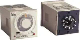


GE1A-B10HAD24
ELECTROMECHANICAL MULTIFUNCTION TIMER
- Manufacturer: IDEC
- Product type: Analogue Timers
- Product Range:GE1A Series; Timer Functions:On-Delay; No. of Timing Ranges:8Ranges; Time Min:0.1min; Time Max:10h; Timer Output:2 Changeover Relays; Supply Voltag 83C9523
- SVHC: No SVHC (16-Jul-2019)
- Time Max: 10h
- Time Min: 0.1min
- Timer Output: 2 Changeover Relays
- Product Range: GE1A Series
- Timer Functions: On-Delay
- Current Rating Nom: 5A
- Panel Cutout Width: 45mm
- Supply Voltage Max: 24V
- Panel Cutout Height: 45mm
- No. of Timing Ranges: 8Ranges
- Connection / Termination: Screw Terminals
| Delivery and price | |
|---|---|
| Units per pack | 250 |
| Price | 26.04 € |
| Current stock | 10+ |
| Lead time | 30 days |
_**Timers**_

GE1A Series

**GE1A Series — Single Function ON Delay Timers** ~~eee~~

**Key features of the GE1A series include:**

- **DPDT or SPDT + instantaneous SPDT**

- **8-pin, octal base**

- **• 8 time ranges**

- **Repeat error ±0.2% maximum**

- **Large, clear knob for easy setting**

- **Instant monitoring of operational status by LED indicators**

|**Specifications**<br>SC|**Rated Operating Voltage**<br>SC|**Rated Operating Voltage**<br>SC|24V AC/DC<br>100 to 120V AC<br>220 to 240V AC|
|---|---|---|---|
||**Voltage Tolerance**<br>SCpe||AC: 85 to 110%<br>DC: 90 to 110%|
||**Contact Rating**<br>pe<br>po||240V AC/5A<br>24V DC/5A|
||**Contact Form**<br>po<br>po<br>po||DPDT or SPDT+ instantaneous SPDT|
||**Repeat Error**<br>po||±0.2% ±10msec maximum|
||**Voltage Error**<br>po<br>po||±0.5% ±10msec maximum|
||**Temperature Error**<br>po<br>po||±3% maximum|
||**Setting Error**<br>po<br>po||±10% maximum|
||**Reset Time**<br>po||0.1 sec maximum|
||**Insulation Resistance**<br>po<br>po||100M<br>Ω<br>minimum (500V DC megger)|
||**Dielectric Strength**<br>BS||Between power and output terminals: 1,500V AC, 1<br>minute<br>Between contact circuits: 750V AC, 1 minute|
||**Vibration Resistance**<br>pe||Damage limits: Amplitude 0.75mm, 10 to 55 Hz<br>Operating extremes: Amplitude 0.5mm, 10 to 55 Hz|
||**Shock Resistance**<br>pe<br>po||Damage limits: 500m/s2 (Approx. 50G)|
||**Power Consumption**<br>po|**GE1A-B**<br>po|24V AC type: 1.6 VA|
||||24V DC type: 1.0W|
||||110V AC type: 3.8 VA|
||||220V AC type: 7.7 VA|
|||**GE1A-C**|24V AC type: 2.0 VA|
||||24V DC type: 0.8W|
||||110V AC type: 3.5 VA|
||||220V AC type: 8.0 VA|
||**Electrical Life**<br>po||100,000 operations minimum (at full rated load)|
||**Mechanical Life**<br>po<br>po||10,000,000 operations minimum|
||**Operating Temperature**<br>po<br>po||–10 to +55°C (without freezing)|
||**Operating Humidity**<br>po<br>~~po~~||35 to 85% RH (without freezing)|


**GE1A Table of Contents** Part Number List — G-55 Timing Diagrams — G-55 GE1A Accessories — G-56 GE1A Dimensions — G-57

_**www.idec.com**_

_**USA: (800) 262-IDEC or (408) 747-0550,   Canada: (888) 317-IDEC**_

_**G-54**_

_**Timers**_

GE1A Series

## **Part Numbering List**

|**Mode of**<br>**Operation**|**Contact**|**Contact**|**Output**|**Rated**<br>**Voltage**|**Rated**<br>**Voltage**|**Rated**<br>**Voltage**|**Rated**<br>**Voltage**|**Rated**<br>**Voltage**|**Rated**<br>**Voltage**|**Rated**<br>**Voltage**|**Rated**<br>**Voltage**|**Rated**<br>**Voltage**|**Rated**<br>**Voltage**|**Time**<br>**Range**|**Time**<br>**Range**|**Complete**<br>**Part No.**|**Complete**<br>**Part No.**|**Complete**<br>**Part No.**|**Complete**<br>**Part No.**|**Complete**<br>**Part No.**|**Complete**<br>**Part No.**|**Complete**<br>**Part No.**|
|---|---|---|---|---|---|---|---|---|---|---|---|---|---|---|---|---|---|---|---|---|---|---|
|ON-Delay|Delayed SPDT +<br>Instantaneous SPDT||24V DC/<br>120V AC,<br>5A<br>240V AC,<br>5A|24V AC/DC<br>110-120V AC<br>220-240V AC<br>24V AC/DC<br>110-120V AC<br>220-240V AC<br>24V AC/DC<br>110-120V AC<br>220-240V AC<br>24V AC/DC<br>110-120V AC<br>220-240V AC||||||||||0.1s to 10m|||||||||
|||||||||||||||0.1m to 10h|||||||||
||Delayed DPDT|||||||||||||0.1s to 10m|||||||||
|||||||||||||||0.1m to 10h|||||||||
||||||||||||||||||||||||
|||||**Timing Diagrams/Schematics**|||||||||||||||||||
||||||||||||||||||||||||
|||**GE1A-B**<br>**GE1A-C**|||||||||||||||||||||
|||**Delayed SPDT + Instantaneous SPDT**|||||||||||||||**Delayed DPDT**||||||
|**Operation**<br>**Mode Selection**||1<br>2<br>6<br>5<br>7<br>8<br>4<br>3<br>POWER<br>(+)<br>(-)|||||||||||||||1<br>2<br>6<br>5<br>7<br>8<br>4<br>3<br>POWER<br>(+)<br>(-)||||||
|**ON-Delay 1**<br>**A**<br>MODE||**Item**<br>Power<br>Delayed<br>Indicator<br>**Terminal No.**<br>2-7 (8p)<br>(Power)<br>5-8 (8p)<br>(NC)<br>6-8 (8p)<br>(NO)<br>POWER<br>OUT<br>Contact<br>1-4<br>1-3<br>(NC)<br>(NO)<br>Instan-<br>taneous<br>Contact|||**Operation**<br>Set Time||||||||||||**Item**<br>Power<br>Delayed<br>Indicator<br>**Terminal No.**<br>2-7 (8p)<br>(Power)<br>(NC)<br>(NO)<br>POWER<br>OUT<br> <br>Contact<br>1-4, 5-8 (8p)<br>1-3, 6-8 (8p)|||**Operation**<br>Set Time|||
||||||||||||||||||||||||
||||||||||||||||||||||||
||||||||||||||||||||||||
||||||||||||||||||||||||
||||||||||||||||||||||||
||||||||||||||||||||||||
||||||||||||||||||||||||
||||||||||||||||||||||||
||||||||||||||||||||||||
||||||||||||||||||||||||
||||||||||||||||||||||||
||||||||||||||||||||||||
||||||||||||||||||||||||
||||||||||||||||||||||||


**G**

_**www.idec.com**_

_**USA: (800) 262-IDEC or (408) 747-0550,   Canada: (888) 317-IDEC**_

_**G-55**_

_**Timers**_

GE1A Series

**==> picture [313 x 533] intentionally omitted <==**

**----- Start of picture text -----**<br>
Accessories<br>Mounting Accessories<br>Style Appearance Part No.<br>8-Pin Screw Terminal<br>SR2P-05<br>(dual tier)<br>Se<br>8-Pin Fingersafe Socket SR2P-05C<br>DIN Rail/<br>Surface<br>pe<br>Mounting<br>Accessories<br>8-Pin Screw Terminal SR2P-06<br>Se<br>DIN Mounting Rail BNDN1000<br>Length 1000mm<br>fo<br>G<br>8-Pin Solder Terminal SR2P-51<br>—2<br>Panel<br>Mounting  Screw Terminal Socket SR6P-M08G<br>Accessories<br>a2<br>Panel Mount Adapter GE9Z-AD<br>Tre<br>Other Accessories<br>Style Appearance Part No.<br>Dust Cover GE9Z-C48<br>Timers<br>**----- End of picture text -----**<br>


_**www.idec.com**_

_**G-56**_

_**USA: (800) 262-IDEC or (408) 747-0550,   Canada: (888) 317-IDEC**_

_**Timers**_

GE1A Series

## **Dimensions: GE1A Series**

## **GE1A Timer**

**==> picture [118 x 420] intentionally omitted <==**

**----- Start of picture text -----**<br>
0.4 0.6<br>0.2 0.8<br>M S X1 X10<br>POWER GE1A OUT<br>48.0<br>Ø35.0<br>44.8<br>4 5<br>3 6<br>2 7<br>1 8<br>48.0<br>4.2<br>10.2<br>6.0<br>69.8<br>10.9 14.2<br>44.8<br>**----- End of picture text -----**<br>


**==> picture [278 x 350] intentionally omitted <==**

**----- Start of picture text -----**<br>
8-Pin SR2P-05<br>36 32 when<br>8 using BAA DIN Rail (BAA) Terminal<br>M3.5 Screw Arrangement<br>2-ø4.2 Mounting Hole 5 4<br>(M4 screw hole) 6 3<br>29<br>7 2<br>4.4max. 5min. 8 1<br>ø4.2<br>Mounting  16.5 (TOP VIEW)<br>29 Hole 20<br>7.9max.<br>28.5<br>ø3.6min.<br>8-Pin SR2P-06 Dimensions in inches (mm)<br>40<br>25.5 when<br>8 using BAA Terminal<br>DIN Rail (BAA) Arrangement<br>M3.5 Screw 2-ø4.2 Mounting Hole 6 5 4 3<br>(M4 screw hole)<br>33<br>4.9max. 5min.<br>ø4.2 7 8 1 2<br>33 Mounting  18 ø3.6min. (TOP VIEW)<br>Hole<br>22 7.9max.<br>52 33 ø25 52<br>3<br>3<br>60 ø25<br>1<br>**----- End of picture text -----**<br>


**==> picture [26 x 28] intentionally omitted <==**

**----- Start of picture text -----**<br>
G<br>**----- End of picture text -----**<br>


## **GE1A Timer Panel Cutout**

**==> picture [77 x 8] intentionally omitted <==**

**----- Start of picture text -----**<br>
45.0 (+0.6, –0)<br>**----- End of picture text -----**<br>


**==> picture [8 x 78] intentionally omitted <==**

**----- Start of picture text -----**<br>
45.0 (+0.6, –0)<br>**----- End of picture text -----**<br>


_**www.idec.com**_

_**USA: (800) 262-IDEC or (408) 747-0550,   Canada: (888) 317-IDEC**_

_**G-57**_

_**Timers**_

General Instructions

## **General Instructions for All Timer Series**

## **Load Current**

With inductive, capacitive, and incandescent lamp loads, inrush current more than 10 times the rated current may cause welded contacts and other undesired effects. The inrush current and steady-state current must be taken into consideration when specifying a timer.

## **Contact Protection**

Switching an inductive load generates a counter-electromotive force (back EMF) in the coil. The back EMF will cause arcing, which may shorten the contact life and cause imperfect contact. Application of a protection circuit is recommended to safeguard the contacts.

## **Temperature and Humidity**

Use the timer within the operating temperature and operating humidity ranges and prevent freezing or condensation. After the timer has been stored below its operating temperature, leave the timer at room temperature for a sufficient period of time to allow it to return to operating temperatures before use.

## **Time Setting**

The time range is calibrated at its maximum time scale; so it is desirable to use the timer at a setting as close to its maximum time scale as possible. For a more accurate time delay, adjust the control knob by measuring the operating time with a watch before application.

## **Input Contacts**

Use mechanical contact switch or relay to supply power to the timer. When driving the timer with a solid-state output device (such as a two-wire proximity switch, photoelectric switch, or solid-state relay), malfunction may be caused by leakage current from the solid-state device. Since AC types comprise a capacitive load, the SSR dielectric strength should be two or more times the power voltage when switching the timer power using an SSR **.**

Generally, it is desirable to use mechanical contacts whenever possible to apply power to a timer or its signal inputs. When using solid state devices, be cautious of inrushes and back-EMF that may exceed the ratings on such devices. Some timers are specially designed so that signal inputs switch at a lower voltage than is used to power the timer (models designated as “B" type).

## **Environment**

Avoid contact between the timer and sulfurous or ammonia gases, organic solvents (alcohol, benzine, thinner, etc.), strong alkaline substances, or strong acids. Do not use the timer in an environment where such substances are prevalent. Do not allow water to run or splash on the timer.

## **Vibration and Shock**

**G**

##

Excessive vibration or shocks can cause the output contacts to bounce, the timer should be used only within the operating extremes for vibration and shock resistance. In applications with significant vibration or shock, use of hold down springs or clips is recommended to secure a timer to its socket.

## **Timing Accuracy Formulas**

Timing accuracies are calculated from the following formulas:

**Repeat Error** = ± 1 x Maximum Measured Value – Minimum Measured Value x 100% 2 Maximum Scale Value

**Voltage Error** = ± Tv - Tr x 100% Tr

TTr:v: Average of measured values at voltage V Average of measured values at the rated voltage

## **Temperature Error**

= ± Tt - T20 x 100% T20

Tt: Average of measured values at °C T20: Average of measured values at 20°C

**Setting Error** = ± Average of Measured Values - Set Value x 100% Maximum Scale Value

_**www.idec.com**_

_**G-68**_

_**USA: (800) 262-IDEC or (408) 747-0550,   Canada: (888) 317-IDEC**_
Updated at April 29, 2026
Founded in 1945, IDEC is a globally recognized leader in industrial automation, machine safety, and control products. Renowned for pioneering innovations in Human-Machine Interface (HMI) systems, the company is dedicated to creating a safe and efficient harmony between advanced workplace technology and human operators. At the core of IDEC’s extensive portfolio is a comprehensive selection of high-performance relays designed for demanding industrial environments. This includes a broad range of electromechanical power relays, solid-state relays, contactors, and critical safety relays, supported by a wide array of specialized relay accessories to ensure reliable and efficient switching. Beyond switching components, IDEC provides complete solutions for modern control panels and automated systems. Their robust engineering extends to advanced panel displays and instrumentation, precision light sensors, and dependable AC/DC power converters. With additional offerings in industrial switches, visual signaling units, and DIN rail terminal blocks, IDEC equips engineers with the high-quality components required to build secure, next-generation automation infrastructure.
About Novapart
Novapart is a B2B electronic component broker specialising in stock shortages and cost reduction. We source hard-to-find parts and identify compliant alternatives across a catalogue of 410,000+ components from 500+ manufacturers.
Learn more →Stock Shortage Specialist
When a component is unavailable, discontinued or has an unacceptable lead time, we tap into our network of vetted European and Asian distributors to source what you need — without compromising on quality or traceability.
Request a quote →Compliant Alternatives
We identify pin-to-pin, electrically equivalent substitutes that meet the same certifications (RoHS, AEC-Q100, REACH) as your original specification — validated against datasheets, not just part numbers. Often at a lower cost.
BOM Analysis service →