
Image not available
Illustrative purposes only

GB01SLT06-214
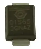
DIODE, SCHOTTKY, 1A, 650V, DO-214AA-2
⚠️ Reference pricing provided. In case of supply shortages, we will connect you with our trusted procurement partners to ensure your project's continuity.
- Manufacturer: GENESIC SEMICONDUCTOR
- Product type: Silicon Carbide Schottky Diodes
- No. of Pins: 2 Pin
- Product Range: 650V Series
- Diode Mounting: Surface Mount
- Diode Case Style: DO-214AA (SMB)
- Diode Configuration: Single
- Average Forward Current: 1A
- Total Capacitive Charge: 7nC
- Operating Temperature Max: 175°C
- Repetitive Peak Reverse Voltage: 650V
| Delivery and price | |
|---|---|
| Units per pack | 15000 |
| Price | 0.948 € |
| Current stock | 10+ |
| Lead time | 30 days |
Datasheet

## **GB01SLT06-214** ## **Silicon Carbide Power Schottky Diode** ## **Features** ## **Package** **==> picture [70 x 9] intentionally omitted <==** **----- Start of picture text -----**<br> RoHS Compliant<br>**----- End of picture text -----**<br> - Industry’s leading low leakage currents |**VRRM**|**=**|**650 V**| |---|---|---| |**IF (Tc = 25°C)**|**=**|**2.5 A**| |**IF (Tc**≤**150°C)**|**=**|**1 A**| |**QC**|**=**|**7 nC**| - 175 °C maximum operating temperature - Temperature independent switching behavior - Superior surge current capability - Positive temperature coefficient of VF - Extremely fast switching speeds - Superior figure of merit QC/IF **==> picture [21 x 34] intentionally omitted <==** **----- Start of picture text -----**<br> PIN 1<br>PIN 2<br>**----- End of picture text -----**<br> **SMB / DO – 214AA** ## **Advantages** - Low standby power losses - Improved circuit efficiency (Lower overall cost) - Low switching losses - Ease of paralleling devices without thermal runaway - Smaller heat sink requirements - Low reverse recovery current - Low device capacitance - Low reverse leakage current at operating temperature ## **Applications** - Power Factor Correction (PFC) - Switched-Mode Power Supply (SMPS) - Solar Inverters - Wind Turbine Inverters - Motor Drives - Induction Heating - Uninterruptible Power Supply (UPS) - High Voltage Multipliers ## **Maximum Ratings at Tj = 175 °C, unless otherwise specified** |**Parameter**|**Symbol **||**Conditions**|**Values**|**Unit**| |---|---|---|---|---|---| |Repetitivepeak reverse voltage|VRRM|||650|V| |Continuousforward current|IF||TC = 25 °C|2.5|A| |Continuousforward current|IF||TC ≤ 150 °C|1|A| |RMS forward current|IF(RMS)||TC ≤ 150 °C|2|A| |Surge non-repetitive forward current, Half Sine<br>Wave|IF,SM|TC= 25 °C, t|= 25 °C, tP= 10 ms|10|A| |Non-repetitive peak forward current|IF,max|TC = 25 °C,tP= 10µs||65|A| |I<br>2t value|∫i<br>2dt|TC= 25 °C, t|= 25 °C, tP= 10 ms|0.5|A<br>2S| |Power dissipation|Ptot||TC = 25 °C|64|W| |Operatingand storage temperature|Tj ,Tstg|||-55 to 175|°C| ## **Electrical Characteristics at Tj = 175 °C, unless otherwise specified** |**Electrical Characteristics at Tj = 175 °C, unless otherwise specifiedj = 175 °C, unless otherwise specified = 175 °C, unless otherwise specified**<br>**Parameter**<br>**Symbol**<br>**Conditions**|**Electrical Characteristics at Tj = 175 °C, unless otherwise specifiedj = 175 °C, unless otherwise specified = 175 °C, unless otherwise specified**<br>**Parameter**<br>**Symbol**<br>**Conditions**|**Electrical Characteristics at Tj = 175 °C, unless otherwise specifiedj = 175 °C, unless otherwise specified = 175 °C, unless otherwise specified**<br>**Parameter**<br>**Symbol**<br>**Conditions**|**Values**|**Unit**| |---|---|---|---|---| |**Parameter**<br>**Symbol**<br>**Conditions**<br>**min.**|||**typ. **|**Unit**<br>**max.**| |Diode forward voltage<br>VF<br>IF= 1 A, Tj= 25 °C<br>IF= 1 A,Tj= 175 °C|||1.5<br>2.3<br>~~|~~|2.0<br>V<br>3.0| |Reverse current<br>IR<br>VR= 650 V, Tj= 25 °C<br>VR = 650 V,Tj= 175 °C|||1<br>5<br>~~|~~|10<br>µA<br>50| |Total capacitive charge<br>QC|IF≤ IF,MAX<br>dIF/dt = 200 A/μs<br>Tj = 175°C<br>~~eo~~|VR= 400 V<br>~~eo~~|7<br>~~eo~~<br>~~eee~~|nC<br>~~eee~~| |Switchingtime<br>ts||VR= 400 V<br>~~eo~~<br>~~ee~~|< 20<br>~~eo~~<br>~~ee~~<br>~~eee~~|ns<br>~~eee~~| |j<br>Total capacitance<br>C<br>VR= 1 V, f = 1 MHz, Tj= 25 °C<br>VR = 400 V,f = 1 MHz,Tj= 25 °C|||76<br>12<br>~~eee~~|pF<br>~~eee~~| http://www.genesicsemi.com/commercial-sic/sic-schottky-rectifiers/ Pg **1** of 4 Aug 2014 **GB01SLT06-214** **==> picture [252 x 228] intentionally omitted <==** **Figure 1: Typical Forward Characteristics** **==> picture [226 x 179] intentionally omitted <==** **Figure 3: Power Derating Curve** **==> picture [226 x 180] intentionally omitted <==** **Figure 5: Typical Junction Capacitance vs Reverse Voltage Characteristics** **==> picture [226 x 180] intentionally omitted <==** **Figure 2: Typical Reverse Characteristics** **==> picture [226 x 179] intentionally omitted <==** **==> picture [209 x 17] intentionally omitted <==** **----- Start of picture text -----**<br> Figure 4: Current Derating Curves (D = tP/T, tP= 400 µs)<br> (Considering worst case Zth conditions )<br>**----- End of picture text -----**<br> **==> picture [226 x 180] intentionally omitted <==** **Figure 6: Typical Capacitive Energy vs Reverse Voltage Characteristics** http://www.genesicsemi.com/commercial-sic/sic-schottky-rectifiers/ Pg **2** of 4 Aug 2014 ## **GB01SLT06-214** **Figure 7: Current vs Pulse Duration Curves at TC = 160 °C** **Figure 8: Transient Thermal Impedance** ## **Package Dimensions:** ## **SMB / DO - 214AA PACKAGE OUTLINE** **==> picture [204 x 15] intentionally omitted <==** **----- Start of picture text -----**<br> Lot Code<br>Abbreviated Part Name<br>**----- End of picture text -----**<br> ## **NOTE** 1. CONTROLLED DIMENSION IS INCH. DIMENSION IN BRACKET IS MILLIMETER. 2. DIMENSIONS DO NOT INCLUDE END FLASH, MOLD FLASH, MATERIAL PROTRUSIONS http://www.genesicsemi.com/commercial-sic/sic-schottky-rectifiers/ Pg **3** of 4 Aug 2014 **==> picture [252 x 37] intentionally omitted <==** ## **GB01SLT06-214** ||**Revision History**|**Revision History**|| |---|---|---|---| |Date|Revision|Comments|Supersedes| |2014/08/26|1|Updated Electrical Characteristics|| |2013/09/09|0|Initial release|| ||||| Published by GeneSiC Semiconductor, Inc. 43670 Trade Center Place Suite 155 Dulles, VA 20166 GeneSiC Semiconductor, Inc. reserves right to make changes to the product specifications and data in this document without notice. GeneSiC disclaims all and any warranty and liability arising out of use or application of any product. No license, express or implied to any intellectual property rights is granted by this document. Unless otherwise expressly indicated, GeneSiC products are not designed, tested or authorized for use in life-saving, medical, aircraft navigation, communication, air traffic control and weapons systems, nor in applications where their failure may result in death, personal injury and/or property damage. http://www.genesicsemi.com/commercial-sic/sic-schottky-rectifiers/ Pg **4** of 4 Aug 2014 **GB01SLT06-214** **==> picture [175 x 37] intentionally omitted <==** ## **SPICE Model Parameters** This is a secure document. Please copy this code from the SPICE model PDF file on our website (http://www.genesicsemi.com/images/products_sic/rectifiers/GB01SLT06-214_SPICE.pdf) into LTSPICE (version 4) software for simulation of the GB01SLT06-214. * MODEL OF GeneSiC Semiconductor Inc. * * $Revision: 1.0 $ * $Date: 09-SEP-2013 $ * * GeneSiC Semiconductor Inc. * 43670 Trade Center Place Ste. 155 * Dulles, VA 20166 - - COPYRIGHT (C) 2013 GeneSiC Semiconductor Inc. * ALL RIGHTS RESERVED * - These models are provided "AS IS, WHERE IS, AND WITH NO WARRANTY - OF ANY KIND EITHER EXPRESSED OR IMPLIED, INCLUDING BUT NOT LIMITED - TO ANY IMPLIED WARRANTIES OF MERCHANTABILITY AND FITNESS FOR A - PARTICULAR PURPOSE." - Models accurate up to 2 times rated drain current. - - Start of GB01SLT06-214 SPICE Model - .SUBCKT GB01SLT06 ANODE KATHODE D1 ANODE KATHODE GB01SLT06_25C; Call the Schottky Diode Model D2 ANODE KATHODE GB01SLT06_PIN; Call the PiN Diode Model .MODEL GB01SLT06_25C D + IS 3.57E-18 RS 0.49751 + TRS1 0.0057 TRS2 2.40E-05 + N 1 IKF 322 + EG 1.2 XTI 3 + CJO 9.12E-11 VJ 0.371817384 + M 1.527759838 FC 0.5 + TT 1.00E-10 BV 650 + IBV 1.00E-03 VPK 650 + IAVE 1 TYPE SiC_Schottky + MFG GeneSiC_Semiconductor .MODEL GB01SLT06_PIN D + IS 5.73E-11 RS 0.72994 + N 5 IKF 800 + EG 3.23 XTI -14 + FC 0.5 TT 0 + BV 650 IBV 1.00E-03 + VPK 650 IAVE 1 + TYPE SiC_PiN .ENDS * * End of GB01SLT06-214 SPICE Model Sep 2013 http://www.genesicsemi.com/commercial-sic/sic-schottky-rectifiers/ Pg **1** of 1
Updated at February 9, 2023
About Novapart
Novapart is a B2B electronic component broker specialising in stock shortages and cost reduction. We source hard-to-find parts and identify compliant alternatives across a catalogue of 540,000+ components from 500+ manufacturers.
Learn more →Stock Shortage Specialist
When a component is unavailable, discontinued or has an unacceptable lead time, we tap into our network of vetted European and Asian distributors to source what you need — without compromising on quality or traceability.
Request a quote →Compliant Alternatives
We identify pin-to-pin, electrically equivalent substitutes that meet the same certifications (RoHS, AEC-Q100, REACH) as your original specification — validated against datasheets, not just part numbers. Often at a lower cost.
BOM Analysis service →