
Image not available
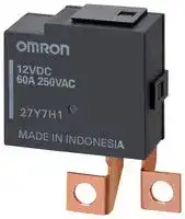
Illustrative purposes only

G9TA-U1ATH DC12
POWER RELAY, SPST-NO, 60A, 250V, BRACKET
⚠️ Reference pricing provided. In case of supply shortages, we will connect you with our trusted procurement partners to ensure your project's continuity.
- Manufacturer: OMRON ELECTRONIC COMPONENTS
- Product type: Power Relays
- Coil Type: Latching Single Coil
- Coil Voltage: 12VDC
- Product Range: G9TA Series
- Relay Mounting: Bracket
- Coil Resistance: 145ohm
- Contact Current: 60A
- Relay Terminals: Solder
- Contact Material: Silver Alloy
- Contact Voltage VAC: 250V
- Contact Configuration: SPST-NO
| Delivery and price | |
|---|---|
| Units per pack | 100 |
| Price | 7.01 € |
| Current stock | 10+ |
| Lead time | 30 days |
Datasheet

G9TA AC Power Latching Relay
## **60 A High power latching relay**
- High power switching, Compact size
- High magnetic latching force provides vibration resistance
- Low contact resistance
## **RoHS Compliant**
## **Model Number Structure**
## **G9TA-** **1 A**
1 2 3 4
2. Number of poles
1. Relay Function
- 1: 1-Pole
- U: Single-winding latching
## **Application Examples**
- Smart Meter • Lighting control
- PV Inverter • EV Charger
- K: Double-winding latching
3. Contact Form 4. Terminal shape
- A: SPST-NO TH: M5 securing screw
TW: Welding terminals
## **Ordering Information**
|Classification<br>Contact Form<br>Terminal Shape|Enclosure rating|Model|Rated coil voltage|Minimumpackingunit|
|---|---|---|---|---|
|Single coil<br>SPST-NO<br>M5 securingscrew<br>Weldingterminals<br>Double coils<br>M5 securingscrew<br>Weldingterminals|Flux protection|G9TA-U1ATH<br>G9TA-U1ATW<br>G9TA-K1ATH<br>G9TA-K1ATW|12 VDC<br>12 VDC|25 pcs/tray|
|Note. When ordering, add the rated coil voltage to the model number.|||||
|Example: G9TA-U1ATHDC12<br>Rated coil voltage<br>~~~To~~|||||
|However, the notation of the coil voltage on the product case as well as on the packing will be marked as[][] VDC.|||||
Note. When ordering, add the rated coil voltage to the model number.
## **Ratings**
## **Coil**
## **Single-winding Latching Type**
||Item|Rated current (mA)|Coil resistance (Ω)|Must set voltage||Must reset<br>voltage||Max. voltage|Power consumption|
|---|---|---|---|---|---|---|---|---|---|
|Rated Voltage|(V)||||% of rated voltage||||Set coil(W)<br>Reset coil(W)|
|DC|12|83|145|80% max.||80% max.||110% max.|Approx. 1.0|
|**Double-winding Latching Type**|**Double-winding Latching Type**|||||||||
||Item|Rated current (mA)|Coil resistance (Ω)|Must set voltage||Must reset<br>voltage||Max. voltage|Power consumption|
|Rated Voltage|(V)|Set coil<br>Reset coil|Set coil<br>Reset coil||% of rated voltage||||Set coil(W)<br>Reset coil(W)|
|DC|12|217<br>217|55<br>55|80% max.||80% max.||110% max.|Approx. 2.6<br>Approx. 2.6|
## **Double-winding Latching Type**
Note 1. The rated current and coil resistance were measured at a coil temperature of 23°C with tolerances of ± 10%.
Note 2. The operating characteristics are measured at a coil temperature of 23°C.
Note 3. The maximum permissible voltage is the maximum value of the fluctuation range for the Relay coil operating power supply and was measured at an ambient temperature of 23°C.
## **Contacts**
|Model<br>Item<br>Load|G9TA-U1A/G9TA-K1A|G9TA-U1A/G9TA-K1A|
|---|---|---|
||Resistive load|Inductive load(PF=0.5)|
|Contact type|SPST-NO||
|Contact material|AgAlloy||
|Rated load|60 A at 250 VAC||
|Rated carrycurrent|60 A||
|Max. switchingvoltage|250 VAC||
|Max. switchingcurrent|60 A||
**1**
G9TA
**AC Power Latching Relay**
## **Characteristics**
|Item|Item|G9TA-U1A|G9TA-K1A|
|---|---|---|---|
|Contact resistance *1||2 mΩmax.||
|Set time *2||30 ms max.|20 ms max.|
|Reset time *2||30 ms max.|20 ms max.|
|Minimum pulse width||100 ms||
|Maximum pulse width||1,000 ms||
|Insulation resistance *3||1,000 MΩmin.||
|Dielectric strength|Between coil and contacts|4,000 VAC, 50/60 Hz for 1 min||
||Between contacts of the<br>same polarity|1,500 VAC, 50/60 Hz for 1 min||
|Impulse withstand<br>voltage|Between coil and contacts|6 kV||
|Vibration resistance|Destruction|10 to 150 to 10 Hz, f < 60 Hz: Constant amplitude 0.075 mm, f > 60 Hz: Constant acceleration 9.8 m/s2||
||Malfunction|10 to 55 to 10 Hz, 0.75 mm single amplitude (1.5 mm double amplitude)||
|Shock resistance|Destruction|1,000 m/s2||
||Malfunction|100 m/s2||
|Durability|Mechanical|100,000 operations min. (at 7,200 operations/h)||
||Electrical *4|5,000 operations, resistive load and then<br>5,000 operations, inductive load (PF=0.5) (operation: ON for 10 sec, OFF for 20 sec) *5||
|Ambient operating temperature||-40 to 85°C (with no icing or condensation)||
|Ambient operating humidity||5 to 85%||
|Weight||Approx. 42 g||
Note. The values given above are initial values.
*1. Measurement conditions: 24 VDC, 1 A, voltage drop method.
*2. Measurement conditions: Rated operating voltage applied, not including contact bounce. Ambient temperature: 23°C
*3. Measurement conditions: The insulation resistance was measured with a 500 VDC megohm meter at the same locations as the dielectric strength was measured. *4. Contact your OMRON sales representative for Electrical Durability technical data.
*5. The characteristic meets IEC62055-31 test requirement.
**2**
G9TA
**AC Power Latching Relay**
(Unit: mm)
## **Dimensions**
## **G9TA-U1ATH**
**==> picture [360 x 221] intentionally omitted <==**
**----- Start of picture text -----**<br>
37.1 max.<br>Terminal arrangement/Internal Connections<br>(TOP VIEW)<br>33.5 max. S -<br>30<br>- R<br>1 2 3 4<br>4<br> 4.95 4<br>10 5 9.9 5 6.7 Check carefully the coil polarity of the Relay.<br> 10<br>4.65<br>9.3 Two, 5.5 dia.<br>38.6<br>5±0.05<br>7.7 18.55 Two, @0.64±0.01<br>18 max.<br>14.2<br> 3.7<br>1 1 3.7<br>**----- End of picture text -----**<br>
## **G9TA-U1ATW**
**==> picture [165 x 194] intentionally omitted <==**
**----- Start of picture text -----**<br>
37.1 max.<br>33.5 max. 30<br>8.8<br>4<br>38.6<br>5±0.05<br>7.7 18.55 Two, @0.64±0.01<br>10.6 12 18 max.<br>14.2<br>1 1<br>**----- End of picture text -----**<br>
**==> picture [141 x 83] intentionally omitted <==**
**----- Start of picture text -----**<br>
Terminal arrangement/Internal Connections<br>(TOP VIEW)<br>S -<br>- R<br>1 2 3 4<br>**----- End of picture text -----**<br>
Check carefully the coil polarity of the Relay.
## **G9TA-K1ATH**
**==> picture [356 x 212] intentionally omitted <==**
**----- Start of picture text -----**<br>
37.1 max.<br>Terminal arrangement/Internal Connections<br>(TOP VIEW)<br>33.5 max.<br>30<br>1 2 3 4 5<br>4 S - R<br> 4.95 4<br>5 6.7 Check carefully the coil polarity of the Relay.<br>10 5<br> 10<br>4.65 Two, 5.5 dia.<br>9.3<br>9.9<br>38.6<br>5±0.05 5±0.05<br>7.7<br>13.55 Three, @0.64±0.01<br>18 max.<br>14.2<br>3.7<br>1 1<br>3.7<br>**----- End of picture text -----**<br>
**3**
G9TA
**AC Power Latching Relay**
(Unit: mm)
## **G9TA-K1ATW**
**==> picture [352 x 200] intentionally omitted <==**
**----- Start of picture text -----**<br>
37.1 max.<br>Terminal arrangement/Internal Connections<br>(TOP VIEW)<br>33.5 max. 30<br>1 2 3 4 5<br>S - R<br>8.8 Check carefully the coil polarity of the Relay.<br>4<br>38.6<br>5±0.05 5±0.05<br>7.7<br>13.55 Three, @0.64±0.01<br>10.6 12 18 max.<br>14.2<br>1 1<br>**----- End of picture text -----**<br>
Note 1. Relay is delivered as "reset" status unless specified otherwise. However, the status may change due to the shock from transportation or mounting operations. Therefore, it is recommended the relay should be set to the expected status via a power supply before being used.
Note 2. In order to maintain "set" or "reset" status, the energizing voltage to coil & the pulse width shouldn't lower then the rated value. Note 3. Do not energize both of set and reset coil simultaneously. Note 4. Energizing time longer than 1,000 ms should be avoided.
## **Engineering Data**
**Maximum Switching Capacity G9TA-U1A** **G9TA-K1A**
**==> picture [276 x 125] intentionally omitted <==**
**----- Start of picture text -----**<br>
1000 1000<br>100 AC Resistive Load 100 AC Inductive Load (PF=0.5)<br>60 60<br>10 10<br>1 1<br>1 10 100 250 1000 1 10 100 250 1000<br>Switching voltage (V) Switching voltage (V)<br>Switching current (A) Switching current (A)<br>**----- End of picture text -----**<br>
**4**
G9TA
**AC Power Latching Relay**
## **Safety Precautions**
- **Please refer to "PCB Relays Common Precautions" for correct use.**
## Correct Use
## **Installation**
- The relay contacts are polarized. Incorrect wiring may cause a failure to break the circuit. Wire the Relay with care.
- Install the Relays in locations that are as dry as possible and have as little dust, dirt, and harmful gas.
- Using the Relay under high temperature, high humidity, or harmful gas may deteriorate its performance characteristics due to condensation or corrosive materials, resulting in failure or burn damage to the Relay.
## **Relay Service Life**
- The electrical durability of these Relays is specified as the number of load switching operations under a resistive load and OMRON-specified standard testing conditions.
- The coil drive circuit, ambient environment, switching frequency, or load conditions (e.g., inductive load or capacitor load) may reduce the service life and possibly lead to failure to break. Always confirm the service life in the actual equipment.
## **Wiring**
- Be sure to tighten all screws to the appropriate torque given below.
- Loose screws may result in burning due to abnormal heat generation during energization.
- M5 screws: 1.57 to 2.35 N·m
- Use a spring washer in order to prevent deformation and looseness.
- Allow suitable slack on leads when wiring, and do not apply excessive force to the terminals.
- Application examples provided in this document are for reference only. In actual applications, confirm equipment functions and safety before using the product.
- Consult your OMRON representative before using the product under conditions which are not described in the manual or applying the product to nuclear control systems, railroad systems, aviation systems, vehicles, combustion systems, medical equipment, amusement machines, safety equipment, and other systems or equipment that may have a serious influence on lives and property if used improperly. Make sure that the ratings and performance characteristics of the product provide a margin of safety for the system or equipment, and be sure to provide the system or equipment with double safety mechanisms.
**Note: Do not use this document to operate the Unit.**
## **OMRON Corporation**
**Electronic and Mechanical Components Company**
**Contact: www.omron.com/ecb**
**Cat. No. J220-E1-01** 0318(0318)(O)
**5**
Updated at February 9, 2023
About Novapart
Novapart is a B2B electronic component broker specialising in stock shortages and cost reduction. We source hard-to-find parts and identify compliant alternatives across a catalogue of 410,000+ components from 500+ manufacturers.
Learn more →Stock Shortage Specialist
When a component is unavailable, discontinued or has an unacceptable lead time, we tap into our network of vetted European and Asian distributors to source what you need — without compromising on quality or traceability.
Request a quote →Compliant Alternatives
We identify pin-to-pin, electrically equivalent substitutes that meet the same certifications (RoHS, AEC-Q100, REACH) as your original specification — validated against datasheets, not just part numbers. Often at a lower cost.
BOM Analysis service →