
Image not available
Illustrative purposes only

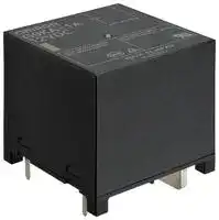
G9KA-1A DC24
Power Relay, SPST-NO, 24 VDC, 200 A, G9KA Series, Through Hole, Non Latching
⚠️ Reference pricing provided. In case of supply shortages, we will connect you with our trusted procurement partners to ensure your project's continuity.
- Manufacturer: OMRON ELECTRONIC COMPONENTS
- Product type: Power Relays
- SVHC: To Be Advised
- Coil Type: Non Latching
- Coil Voltage: 24VDC
- Product Range: G9KA Series
- Relay Mounting: Through Hole
- Coil Resistance: 115.2ohm
- Contact Current: 200A
- Relay Terminals: PC Pin
- Contact Material: Silver Alloy
- Contact Voltage VAC: 800V
- Contact Voltage VDC: -
- Contact Configuration: SPST-NO
| Delivery and price | |
|---|---|
| Units per pack | 10 |
| Price | 47.75 € |
| Current stock | 10+ |
| Lead time | 7 days |
Datasheet

**==> picture [101 x 13] intentionally omitted <==**

**----- Start of picture text -----**<br>
PCB Power Relays<br>**----- End of picture text -----**<br>


**==> picture [105 x 9] intentionally omitted <==**

**----- Start of picture text -----**<br>
¢ 800 VAC/200 A breaking<br>**----- End of picture text -----**<br>


**==> picture [159 x 24] intentionally omitted <==**

**----- Start of picture text -----**<br>
¢ Ambient temperature 85°C<br>¢ High impulse withstand voltage, 10 kV<br>**----- End of picture text -----**<br>


- ¢ Contact gap >4.0 mm (Applied to VDE0126) ¢ Low initial contact resistance <0.2 mQ (when 200 A of current is applied)

**==> picture [145 x 74] intentionally omitted <==**

**----- Start of picture text -----**<br>
RoHS Compliant<br>A Refer to the Precautions on page 4 .<br>Model Number Legend Number Legend Legend<br>**----- End of picture text -----**<br>


**==> picture [543 x 330] intentionally omitted <==**

**----- Start of picture text -----**<br>
Model Number Legend Number Legend Legend Application Examples |<br>G9KA -O0 ¢ Power conditioner inverter G<br>42 * Industrial inverter 9<br>° UPS K<br>1 . Number of Poles 2 . Contact Form A<br>1: 1 - pole A: SPST - NO (1a)<br>Ordering Information<br>Standard SPST - NO (1a) Flux protection G9KA - 1A 2412 VDCVDC 36pcs/box<br>Note . When ordering, add the rated coil voltage to the model number.<br>Example: G9KA - 1A DC12<br>~ TL _ Rated coil voltage<br>Both the coil voltage on the product case and the packing will be marked as DOVDC .<br>Ratings<br>@ Coil<br>Item ; , Must operate voltage | Must release voltage Max. voltage ,<br>Rated current Coil resistance (V) (V) (V) Power consumption<br>Rated voltage (mA) (Q) % of rated voltage (mW)<br>24 VDC Approx . 208 415 . 2 75%© max.max * 5 to 35%° (at 23°C). Approx . y1,012ao *<br>**----- End of picture text -----**<br>


## Ordering Information

Note 1. The rated current and resistance are measured at a coil temperature of 23°C with a tolerance of +10%.

Note 2 ~~.~~ The operating characteristics are measured at a coil temperature of 23°C ~~.~~

- Note 3 ~~.~~ The maximum permissible voltage is the maximum value of the fluctuation range for the relay coil operating power supply and was measured at an ambient temperature of 23°C.

Note 4. Use this relay with coil voltage reduction.

- Power consumption with holding voltage is approx. 1,012 mW (when applying holding voltage at 45%). Please confirm the details on page 4, under @Coil Voltage Reduction (holding voltage) after Relay Operation ~~.~~

- Some mounting directions are not guaranteed ~~.~~ Please confirm the details on page 4 @Coil Voltage Reduction (holding voltage) after Relay Operation ~~.~~

## ® Contacts

Rated 50A at 800 VAC/ load 800 VAC 150 A switch on, 200 A carry current, 200 A switch off Rated carry current 200 A Max ~~.~~ switching voltage 800 VAC

1

G9KA

PCB Power Relays

## Characteristics

**==> picture [444 x 269] intentionally omitted <==**

**----- Start of picture text -----**<br>
||||||||||||||||||||
|---|---|---|---|---|---|---|---|---|---|---|---|---|---|---|---|---|---|---|
|Item|Model|G9KA|-|1A|
|5,000|VAG,|60/60|Hz|for|1|min|
|Dielectric|strengthgm|| Betweensame|polarity contacts of the|||5|o99 vac, 50/60 Hz for|1|min|
|Impulse withstand|Between|coil|and contacts|10|kV|(1.2|x 50|us)|
|voltage|
|oo|:|
|Vibration|resistance|10 to 55 to|10|Hz,|0.5 mm single amplitude|(1.0 mm|double|amplitude)|
|Excitation:|10|to|55|to|10|Hz,|0.5|mm|single|amplitude|(1.0|mm|double|amplitude)|
|Shock|resistance|-|—|
|100,000|operations|min|.|(at|18,000|operations/h)|
|Durability|800 VAC 50 A switch|on,|200 A|carry|current,|50 A|switch|off;|30,000|operations|min.|
|Electrical|(Resistive)|*4|800|VAC|150 A|switch|on,|200 A|carry|current,|200|A|switch|off;|10|operations|min|.|
|(Switching|frequency:|1|second|ON|-|9|seconds OFF|at|85°C)|
|Failure|rate|(M|level)|(Reference|value)|*5|1|Aat5|VDC|
|Coil|holding|voltage|*6|45%|to|60%|of|rated|coil|voltage|
|G|Use conditions|temperaturAmbient op|e|rating|-40°C to +85°C (with no icing or condensation)|
|y|Ambient operating|humidity|| 5% to 85%|

**----- End of picture text -----**<br>


Note ~~.~~ The values given above are initial values at 23°C ~~.~~ (Except Electrical Durability) *1 ~~.~~ | Measurement conditions: 200 A at 6 VDC (after 30 minutes) voltage drop method ~~.~~

*2 ~~.~~ Measurement conditions: Applied rated coil voltage, no contact bouncing ~~.~~ *3 ~~.~~ | Measurement conditions: Measured with a 1,000 VDC megohmmeter at the same point as the dielectric strength was measured ~~.~~

*4. This specification is when diode and zener diode are used. For relay coil, please connect diode and zener diode ~~.~~ For more detail, please refer to @Diode Connection for Operating Coil on page 4.

*5 ~~.~~ The value was measured at a switching frequency of 180 operations/ minute ~~.~~

*6. For the detail regarding holding voltage usage, please refer to @Coil Voltage Reduction (holding voltage) after Relay Operation on page 4 ~~.~~

## Malfunction shock resistance

**==> picture [427 x 149] intentionally omitted <==**

**----- Start of picture text -----**<br>
4,000" Excitation Measurement:<br>, S00 No Excitation Measure the value of contact malfunction. happening. by<br>4 00 applying 3 axes with 6 direction 3 times each .<br>X+ z+ The energized voltage is within the range of the rated<br>400<br>Seq 200 holding voltage.<br>Standard value:<br>Excitation 100 m/s2<br>Z z X -<br>Shock direction 2+<br>Y -<br>**----- End of picture text -----**<br>


**==> picture [182 x 116] intentionally omitted <==**

**----- Start of picture text -----**<br>
Shock direction 2+<br>Y+ | X+<br>| ]<br>X- > Y-<br>Coil terminal<br>z [\][ terminal]<br>**----- End of picture text -----**<br>


**==> picture [546 x 572] intentionally omitted <==**

GOKA

PCB Power Relays

## Precautions

## @ Refer to PCB Relays Common Precautions for general precautions.

> ; ¢ Use diodes with reverse dielectric strength 10 times or more As that of coil rated voltage, and with forward current more than this relay is a high-voltage and high-current type, coil rated current. there is a risk of abnormal heat generation, smoke generation or fire if you use the relay with a contact biode voltage, current, or for a number of times beyond the Relay coil specified range. Use only within the specified ranges. Zenner diode If the power is switched on when the connections are insuffic ~~i~~ ent, there is a risk of abnormal heat ~~‘\~~ generation ~~.~~ Do not connect and use probes and @PCB Terminal Soldering sockets on individual relays ~~.~~ ¢ Solder at 290°C 290°C for 20 seconds 20 seconds seconds (max.) in soldering soldering bath ~~.~~ If the power is switched on whenthe connections ,» * It is not possible to wash wash relay as this as this this is not fully sealed sealed type generation ~~.~~ Please install and use relays under * To reduce the risk of specification deterioration, assemble are insuffic ~~i~~ ent, there is a risk of abnormal heat ~~A)~~ @Assembly recommended conditions. relays in a dust free, low humidity and non ~~-c~~ orrosive gas

- ¢ Solder at 290°C 290°C for 20 seconds 20 seconds seconds (max.) in soldering soldering bath ~~.~~ * It is not possible to wash wash relay as this as this this is not fully sealed sealed type ~~.~~ * To reduce the risk of specification deterioration, assemble

- @Assembly relays in a dust free, low humidity and non ~~-c~~ orrosive gas environment ~~.~~

- ¢ Take care when mounting relays to utilize adequate anchorage on both sides of PCB to optimize heat transfer and reduce risk for both heat and mechanical stress ~~.~~

- ¢ This product weight is about 220 g ~~.~~ Be careful of the strength of PCB. To reduce soldering crack due to heat stress, use

- ¢ @Drop K *Do not use relays that have been dropped as they may not A function properly.

- ®@Coil Voltage Reduction (holding voltage) after Relay Operation

- Use this relay with coil voltage reduction ~~.~~

- * Apply the rated voltage for 0.1 to 3 seconds to the coil first. * The range of coil rated voltage must be set as 100 to 120%, and holding voltage must be 45 to 60%. Do not exceed the ranges due to the change of coil voltage change and so on.

- (Rates Voltage) — (Holing voltage) f ~~o er~~ 0.1 to 3 seconds

- voltage 28.8 Q (DC12) Approx ~~.~~ 5 to 7 ~~.~~ 2 W

- Holding voltage Approx. 1.0 to 1 ~~.~~ 8 W

- eeeRated eCoil ~~ee~~ power consu ~~mp~~ tion * The coil resistances were measured at a coil temperature of 23°C with tolerances of + 10% ~~.~~

- @Diode Connection for Operating Coil * Connect diode or zener diode (or varistor) to the coil (refer to the picture below). Diode is for coil surge absorption ~~.~~ Ensure to include zener diode as there is a possibility of any influence for switching capability when only using diodes ~~.~~

- * Coil has no polarity ~~.~~ Connect the diodes in the reverse polarity of the voltage applied to the coil.

- ¢ The recommended zener diode voltage is 3 times that of the rated coil voltage ~~.~~

- eElectrical Endurance ree ¢ This relay's electrical endurance specification is based on our company's standard test procedure with resistive loads ~~.~~ Relays intended for use with remove; types of drive circuits PWM, capacitive, resistive dropper etc.), types of loads (e ~~.~~ g. capacitive or inductive), and switching cycles (duty and operation timing) must be tested to confirm suitability to the actual intended application.

- * The final failure mode is failure to break the circuit ~~.~~ In such a case, burning may extend to surrounding components. Implement safety circuits and other measures to minimize the risk of mechanical failure.

- ®Micro Load * Thismicro is loads a power such as relay signal switching. for high power switching. Do not use for

4

**==> picture [545 x 408] intentionally omitted <==**

**==> picture [507 x 193] intentionally omitted <==**
Updated at March 24, 2026
About Novapart
Novapart is a B2B electronic component broker specialising in stock shortages and cost reduction. We source hard-to-find parts and identify compliant alternatives across a catalogue of 410,000+ components from 500+ manufacturers.
Learn more →Stock Shortage Specialist
When a component is unavailable, discontinued or has an unacceptable lead time, we tap into our network of vetted European and Asian distributors to source what you need — without compromising on quality or traceability.
Request a quote →Compliant Alternatives
We identify pin-to-pin, electrically equivalent substitutes that meet the same certifications (RoHS, AEC-Q100, REACH) as your original specification — validated against datasheets, not just part numbers. Often at a lower cost.
BOM Analysis service →