
Image not available
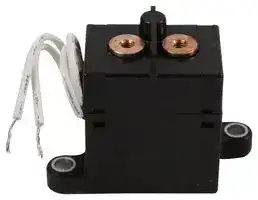
Illustrative purposes only

G9EN-1-UVD DC24
RELAY, SPST-NO, 277VAC, 500VDC, 60A
⚠️ Reference pricing provided. In case of supply shortages, we will connect you with our trusted procurement partners to ensure your project's continuity.
- Manufacturer: OMRON ELECTRONIC COMPONENTS
- Product type: Power Relays
- Coil Type: Non Latching
- Coil Voltage: 24VDC
- Product Range: G9EN-1 Series
- Relay Mounting: Panel Mount
- Coil Resistance: 115.2ohm
- Contact Current: 60A
- Relay Terminals: Screw
- Contact Voltage VAC: 277VAC
- Contact Voltage VDC: 400V
- Contact Configuration: SPST-NO
| Delivery and price | |
|---|---|
| Units per pack | 1 |
| Price | 120.54 € |
| Current stock | 10+ |
| Lead time | 7 days |
Datasheet

**New Product News** ~~[T~~

## **DC Power Relays G9EN-1**

## **DC Power Relays that Enable DC Load Interruption at High Voltage and Current**

- **Enable downsizing, weight saving, and non-polarization in the main contact circuit (contact terminal) by using proprietary design of the contact block.**

- **Contributes to improvements in the ease of wiring and mounting, and error-proofing against faulty wiring.**

- **Class’ smallest: H50 mm × W28 mm × L40 mm**

- **Class’ lightest: approx. 140 g.**

**Accomplished half-size reduction in volume and weight when compared**

**to Omron's same class product (400 VDC, 60 A). ***

***Omron’s internal investigation of August 2012**

## **RoHS Compliant**

Refer to the _Precautions_ on page 4.

## **Model Number Structure**

- G9EN-@-@-@ **-** @ **-** @ **1. Number of Poles 3. Coil Terminals**

— — — — — **1 2 3 4 5**

   - 1: 1 pole Blank: Lead wire output

**2. Contact Form 4. Approved standard**

   - Blank: SPST-NO Blank: Standard

      - UVD: UL/CSA/VDE approved standard type

**5. Special Functions**

**Ordering Information** Terminals Models Contact form Rated coil voltage Model Coil terminals Contact terminals 12 VDC Switching/current conduction models Lead wire Screw terminals SPST-NO G9EN-1 (-UVD) 24 VDC ~~a~~ Note: Two M4 screws are provided for the contact terminal connection. **Ratings**

● **Coil** Rated voltage Rated current Coil resistance Must-operate voltage Must-release voltage Maximum voltage(See note 3) Power consumption 12 VDC 417 mA 28.8 Ω 60% max. of rated 130% of rated voltage 5% min. of rated voltage Approx. 5 W 24 VDC 208 mA 115.2 Ω voltage (at 23°C within 10 minutes) ~~Se~~ Note: 1. The figures for the rated current and coil resistance are for a coil temperature of 23°C and have a tolerance of ±10%. Note: 2. The figures for the operating characteristics are for a coil temperature of 23°C. Note: 3. The figure for the maximum voltage is the maximum voltage that can be applied to the relay coil.

● **Contacts** Item Resistive load Rated load 60 A at 400 VDC Rated carry current 60 A Maximum switching voltage 400 V Maximum switching current 60 A ~~———~~

**1**

**G9EN-1**

**DC Power Relays**

## **Characteristics**

||Item|Item|G9EN-1|
|---|---|---|---|
|Contact voltage drop|||0.1 V max. (for a carry current of 60 A)|
|Operate time|||40 ms max.|
|Release time|||20 ms max.|
|Insulation resistance *1|Between coil and contacts||1,000 MΩmin.|
||Between contacts of the same polarity||1,000 MΩmin.|
|Dielectric strength|Between coil and contacts||2,500 VAC 1 min|
||Between contacts of the same polarity||2,500 VAC 1 min|
|Impulse withstand voltage *2|||4,500 V|
|Vibration resistance *3|Destruction||5 to 200 to 5 Hz, Acceleration: 44.1 m/s2|
||Malfunction||5 to 200 to 5 Hz, Acceleration: 44.1 m/s2|
|Shock resistance|Destruction||490 m/s2|
||Malfunction|Energized|490 m/s2|
|||Deenergized|98 m/s2|
|Mechanical endurance *|4||200,000 min.|
|Electrical endurance *5 *6|||400 VDC, 60 A, 3,000 ops. min.|
|Short-time carry current|||180 A (1 min)|
|Maximum interruption current *6|||500 A at 400 VDC (3 times)|
|Overload interruption *6|||250 A at 400 VDC (200 times min.)|
|Ambient operating temperature|||-40 to 85°C (with no icing or condensation)|
|Ambient operating humidity|||5% to 85%|
|Weight|||Approx. 140 g|


Note: The above values are initial values at an ambient temperature of 23°C unless otherwise specified.

- *1. The insulation resistance was measured with a 500-VDC megohmmeter.

- *2. The impulse withstand voltage was measured with a JEC-212 (1981) standard impulse voltage waveform (1.2 × 50 µs).

- *3. The Upper limit of double amplitude: 10 mm P-P

- *4. The mechanical endurance was measured at a switching frequency of 3,600 operations/hr.

- *5. The electrical endurance was measured at a switching frequency of 60 operations/hr.

- *6. The switching performance and interruption performance were measured with a Zener diode and normal diode connected to absorb coil surge. These performances will be lower if only a normal diode is used.

## **Engineering Data**

● **Maximum Switching Capacity***

● **Electrical Endurance (Switching Performance)***

**==> picture [334 x 166] intentionally omitted <==**

**----- Start of picture text -----**<br>
1,000 10<br>500 5<br>3<br>300<br>1<br>100 0.5<br>0.3<br>50<br>30 0.1<br>0.05<br>0.03<br>10<br>5 0.01<br>3 0.005<br>0.003<br>1 0.001<br>10 30 50 100 300 500 1,000 10 30 50 100 300 500 1,000<br>Switching voltage (V) Switching current (A)<br>●  Carry Current vs. Energizing Time ●  Must-operate Voltage and Must-release Voltage<br>Switching current (A) Operations (×10,000)<br>**----- End of picture text -----**<br>


● **Must-operate Voltage and Must-release Voltage Distributions**

**==> picture [162 x 176] intentionally omitted <==**

**----- Start of picture text -----**<br>
●  Electrical Endurance<br>(Interruption Performance)*<br>1,000<br>500<br>300<br>100<br>50<br>30<br>10<br>5<br>3<br>1<br>10 30 50 100 300 500 1,000<br>Switching current (A)<br>Operations<br>**----- End of picture text -----**<br>


**==> picture [152 x 8] intentionally omitted <==**

**----- Start of picture text -----**<br>
●  Time Characteristic Distributions<br>**----- End of picture text -----**<br>


**(Number of Contacts × Time (ms))**

**(Number of Relays × Percentage of Rated Voltage)**

**==> picture [508 x 172] intentionally omitted <==**

**----- Start of picture text -----**<br>
100,000 30 Must-operate Voltage 30 Operate time<br>Must-release Voltage Release time<br>25 25<br>10,000<br>20 20<br>1,000<br>15 15<br>100<br>10 10<br>10 5 5<br>1<br>10 30 50 100 300 500 1,000 0  20  40  60  80  100 0  3  6  9  12  15<br>Carry current (A) Percentage of rated voltage (%) Time (ms)<br>* The switching performance and interruption performance were measured with a Zener diode and normal diode connected to absorb coil surge. These performanc-<br>es will be lower if only a normal diode is used.<br>Energizing time (s) Number of Relays Number of Contacts<br>**----- End of picture text -----**<br>


**2**

**G9EN-1**

**DC Power Relays**

**==> picture [500 x 211] intentionally omitted <==**

**----- Start of picture text -----**<br>
●  Vibration Malfunction ●  Vibration Resistance ●  Shock Malfunction<br>60 10.0<br>Must-operate Voltage Y Z´<br>50 Unconfirmed area 8.0 Must-release Voltage 500 X´ ZY<br>6.0 400<br>X Y´<br>40 4.0 X 300 Z<br>200<br>2.0<br>100<br>30 0.0<br>Confirmed area<br>−2.0 100<br>20<br>−4.0 200<br>Z´ Deenergized 300 X´<br>10 −6.0<br>400<br>−8.0 Energized<br>0 1 3 5 10 30 50 100 300 500 1000 −10.0 Start After test Y´500<br>Frequency (Hz) Characteristics were measured after applying vibration  The value at which malfunction occurred<br>was measured after applying shock to the<br>at a frequency of 5 to 200 to 5 Hz, acceleration of<br>44.1 m/s [2]  to the test piece (not energized) for 2 hours  3 axes.test piece 3 times each in 6 directions along<br>each in 3 directions.<br>The percentage rate of change is the average value for<br>all of the samples.<br>Note: The Upper limit of double amplitude: 10 mm P-P<br>2Acceleration (m/s) Rate of change (%)<br>**----- End of picture text -----**<br>


## ● **Shock Resistance**

**==> picture [159 x 183] intentionally omitted <==**

**----- Start of picture text -----**<br>
10.0<br>Must-operate Voltage<br>8.0<br>Must-release Voltage<br>6.0<br>4.0<br>2.0<br>0.0<br>−2.0<br>−4.0<br>−6.0<br>−8.0<br>−10.0<br>Start After test<br>Characteristics were measured after applying a shock<br>of 490 m/s [2]   to the test piece 3 times each in 6 directions<br>along 3 axes.<br>The percentage rate of change is the average value for<br>all of the samples.<br>Rate of change (%)<br>**----- End of picture text -----**<br>


## **Dimensions** (Unit: mm)

## **G9EN-1**

**==> picture [494 x 178] intentionally omitted <==**

**----- Start of picture text -----**<br>
Two, M4 Terminal Arrangement/ Mounting Hole<br>(Thread depth of screw terminal:  44 Two, 5.5-dia holes Internal Connections(TOP VIEW) Dimensions(TOP VIEW)<br>6mm minimum.) 15<br>Two, M5 or 5.5-dia holes<br>11<br>17 1<br>40<br>53 53 [±0.1]<br>2<br>64<br>7 8<br>(10)<br>Dimension (mm) Tolerance (mm)<br>17 [±0.1]<br>10 or lower ±0.3 50 44.7 120 [±10]<br>10 to 50 ±0.5<br>50 or higher ±1 7.5<br>28<br>**----- End of picture text -----**<br>


## **Approved standards**

**UL Recognized: File No.E41515**

**CSA Certified: File No.LR31928**

## **VDE Certified: File No.40037488**

|Model|Coil ratings|Contact ratings|Pollution lev|el|Model|Coil ratings|Contact ratings<br>|Pollution level|
|---|---|---|---|---|---|---|---|---|
|**G9EN-1-UVD**|12 V, 24 V|60 A 500 VDC (Resistive)<br>60 A 277 VAC (Resistive)|2||**G9EN-1-UVD**|12 V, 24 V|60 A 500 VDC (Resistive)|2|
||||||||||


**3**

**G9EN-1**

**DC Power Relays**

## **Precautions**

## **WARNING**

Take measures to prevent contact with charged parts when using the Relay for high voltages.

## **Precautions for Correct Use**

Refer to the relevant catalog for common precautions.

1. Be sure to tighten all screws to the appropriate torque given below. Loose screws may result in burning due to abnormal heat generation during energization.

   - M5 screws: 1.57 to 2.35 N·m

   - M4 screws: 0.98 to 1.37 N·m

2. Do not drop or disassemble this Relay. Not only may the Relay fail to meet the performance specifications, it may also result in damage, electric shock, or burning.

3. Do not use these Relays in strong magnetic fields of 800 A/m or higher (e.g., near transformers or magnets). The arc discharge that occurs during switching may be bent by the magnetic field, resulting in flashover or insulation faults.

4. This Relay is a device for switching high DC voltages. If it is used for voltages exceeding the specified range, it may not be possible to interrupt the load and burning may result. In order to prevent fire spreading, use a configuration in which the current load can be interrupted in the event of emergencies.

In order to ensure safety of the system, replace the Relay on a regular basis.

5. If the Relay is used for no-load switching, the contact resistance may increase and so confirm correct operation under the actual operating conditions.

6. These Relays contain pressurized gas. Even in applications with low switching frequencies, the ambient temperature and heat caused by arc discharge in the contacts may allow permeation of the sealed gas, resulting in arc interruption failure. In order to ensure safety of the system, replace Relays on a regular basis.

7. With this Relay, if the rated voltage (or current) is continuously applied to the coil and contacts, and then turned OFF and immediately ON again, the coil temperature, and consequently the coil resistance, will be higher than usual. This means that the must operate voltage will also be higher than usual, exceeding the rated value (“hot start”). In this case, take the appropriate countermeasures, such as reducing the load current or restricting the energizing time or ambient operating temperature.

9. Ensure that a voltage exceeding the specified maximum voltage is not continuously applied to the coil. Abnormal heating in the coil may shorten the lifetime of the insulation coating.

- 10.Do not use the Relay at a switching voltage or current greater than the specified maximum values. Doing so may result in arc discharge interruption failure or burning due to abnormal heating in the contacts.

- 11.The contact ratings are for resistive loads. The electrical endurance with inductive loads is inferior to that of resistive loads. Confirm correct operation under the actual operating conditions.

- 12.Do not use the Relay in locations where water, solvents, chemicals, or oil may come in contact with the case or terminals. Doing so may result in deterioration of the case resin or abnormal heating due to corrosion or contamination of the terminals. Also, if electrolyte adheres to the output terminals, electrolysis may occur between the output terminals, resulting in corrosion of the terminals or wiring disconnections.

- 13.Be sure to turn OFF the power and confirm that there is no residual voltage before replacing the Relay or performing wiring.

- 14.The distance between crimp terminals or other conductive parts will be reduced and insulation properties will be lowered if wires are laid in the same direction from the contact terminals. Use insulating coverings, do not wire in the same direction, and take other measures as required to maintain insulation properties.

- 15.Use either a varistor, or a diode plus Zener diode as a protective circuit against reverse surge in the relay coil. Using a diode alone will reduce the switching characteristics.

- 16.Be sure to use the screws provided with the product for wiring coil terminals and contact terminals. The specified tightening torque cannot be achieved with different screws and may result in abnormal heat generation when energized.

## **Recommended Wire Size**

|Model|Size|
|---|---|
|G9EN-1|14 to 22 mm2|


Note: Use flexible leads.

8. The ripple percentage for DC relays can cause fluctuations in the must-operate voltage or humming. For this reason, reduce the ripple percentage in full-wave rectified power supply circuits by adding a smoothing capacitor. Ensure that the ripple percentage is less than 5%.

- Application examples provided in this document are for reference only. In actual applications, confirm equipment functions and safety before using the product.

• Consult your OMRON representative before using the product under conditions which are not described in the manual or applying the product to nuclear control systems, railroad systems, aviation systems, vehicles, combustion systems, medical equipment, amusement machines, safety equipment, and other systems or equipment that may have a serious influence on lives and property if used improperly. Make sure that the ratings and performance characteristics of the product provide a margin of safety for the system or equipment, and be sure to provide the system or equipment with double safety mechanisms.

**Note: Do not use this document to operate the Unit.**

**OMRON Corporation Electronic and Mechanical Components Company**

**Contact:  www.omron.com/ecb**

**Cat. No. J190-E1-09** 1115 (0812) (O)
Updated at February 9, 2023
About Novapart
Novapart is a B2B electronic component broker specialising in stock shortages and cost reduction. We source hard-to-find parts and identify compliant alternatives across a catalogue of 540,000+ components from 500+ manufacturers.
Learn more →Stock Shortage Specialist
When a component is unavailable, discontinued or has an unacceptable lead time, we tap into our network of vetted European and Asian distributors to source what you need — without compromising on quality or traceability.
Request a quote →Compliant Alternatives
We identify pin-to-pin, electrically equivalent substitutes that meet the same certifications (RoHS, AEC-Q100, REACH) as your original specification — validated against datasheets, not just part numbers. Often at a lower cost.
BOM Analysis service →