
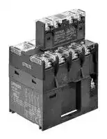


G7Z-4A-20Z-R DC24
Power Relay, 4PST-NO, 24 VDC, 40 A, G7Z Series, DIN Rail, Non Latching
- Manufacturer: OMRON INDUSTRIAL AUTOMATION
- Product type: Power Relays
- SVHC: To Be Advised
- Product Range: G7Z Series
| Delivery and price | |
|---|---|
| Units per pack | 1 |
| Price | 69.95 € |
| Current stock | 10+ |
| Lead time | 30 days |
**New Product**

## **Power Relays G7Z**

## **Compact Electromagnetic Contactors That Switch 40 A at 440 VAC**

- One pole carries 40 A.

UL 508 and UL 840 NO contacts

(resistive 40 A 480 VAC, 60 Hz, 80,000 operations).

- EN 60947-4-1 NO contacts

- (AC1 40 A 440 VAC, 50/60 Hz, 80,000 operations).

- Ideal for supply power to industrial inverters, servo drivers, and other devices, and switching power to motors and other equipment.

- The maximum load capacity of 160 A when using 4-pole parallel connections.

- EN 60947-4-1 certification for mirror contact mechanism obtained by combining the Relay with an Auxiliary Contact Block.

For the most recent information on models that have been certified for safety standards, refer to your OMRON website.

- Conforms to European PV standard (VDE0126).

- Approx. 30% less operation noise than a standard electromagnetic contactor.*

- (Approx. 100 dB reduced to approx. 70 dB.)

- Approx. 50% the volume of a standard electromagnetic contactor* to help downsize control panels.

* According to OMRON investigation of IIEC-AC1 50 A specifications.

Be sure to read the _Safety Precautions_ on page 8 and the _“Precautions for All Relays with Forcibly Guided Contacts”_ .

## **Model Number Structure**

## **Model Number Legend Relay with Auxiliary Contact Block**

- **G7Z-** @ **-** @@ **-** @ **1 2 3**

**1. Relay Contact Configuration**

- 4A: 4PST-NO

- 3A1B: 3PST-NO/SPST-NC

- 2A2B: DPST-NO/DPST-NC

**2. Contact Configuration of Auxiliary Contacts** 20: DPST-NO

## **Relay**

## **G7Z-** @

**1**

**1. Contact Configuration**

- 4A: 4PST-NO

- 3A1B: 3PST-NO/SPST-NC

- 2A2B: DPST-NO/DPST-NC

## **Auxiliary Contact Block**

- 11: SPST-NO/SPST-NC

- 02: DPST-NC

**3. Contact Mechanism of Auxiliary Contacts** Z-R: Bifurcated crossbar contact (Single break)

## **G73Z-** @@ **-** @

**1 2**

**1. Contact Configuration of Auxiliary Contacts**

- 20: DPST-NO

- 11: SPST-NO/SPST-NC

- 02: DPST-NC

**2. Contact Mechanism of Auxiliary Contacts** Z-R: Bifurcated crossbar contact (Single break)

**1**

**G7Z**

**When your order, specify the rated voltage.**

## **Ordering Information**

## **Relay with Auxiliary Contact Block**

|**Number of poles**<br>**(Relay with Auxiliary**<br>**Contact)**|**Contact**|**configuration**|**Contact Mechanism of Auxiliary Contacts**|**Contact Mechanism of Auxiliary Contacts**|
|---|---|---|---|---|
||**Relay**|**Auxiliary Contact Block**|**Single-break models**||
|||||**Rated Voltage**|
|**4 poles + 2 poles**|4PST-NO|DPST-NO|**G7Z-4A-20Z-R**|12, 24 VDC|
|||SPST-NO/SPST-NC|**G7Z-4A-11Z-R**|12, 24 VDC|
|||DPST-NC|**G7Z-4A-02Z-R**|12, 24 VDC|
||3PST-NO/SPST-NC|DPST-NO|**G7Z-3A1B-20Z-R**|12, 24 VDC|
|||SPST-NO/SPST-NC|**G7Z-3A1B-11Z-R**|12, 24 VDC|
|||DPST-NC|**G7Z-3A1B-02Z-R**|12, 24 VDC|
||DPST-NO/DPST-NC|DPST-NO|**G7Z-2A2B-20Z-R**|12, 24 VDC|
|||SPST-NO/SPST-NC|**G7Z-2A2B-11Z-R**|12, 24 VDC|
|||DPST-NC|**G7Z-2A2B-02Z-R**|12, 24 VDC|


- **Note: 1.** Relay contact terminals are M5, and the coil terminals are M3.5.

   **2.** Auxiliary contact block terminals are M3.5.

   **3.** When placing an order, specify the model number and rated supply voltage (12 VDC or 24 VDC).

## **Relay**

|**Number of poles**|**Contact configuration**|**Model**|**Rated Voltage**|
|---|---|---|---|
|**4 poles**|4PST-NO|**G7Z-4A**|12, 24 VDC|
||3PST-NO/SPST-NC|**G7Z-3A1B**||
||DPST-NO/DPST-NC|**G7Z-2A2B**||


- **Note: 1.** Relay contact terminals are M5, and the coil terminals are M3.5.

   **2.** When placing an order, specify the model number and rated supply voltage (12 VDC or 24 VDC).

## **Accessories (Order Separately)**

## **Auxiliary Contact Block**

|**Number of poles**|**Contact Configuration**|**Contact Mechanism of Auxiliary Contacts**|
|---|---|---|
|||**Single-break models**|
|**2 poles**|DPST-NO|**G73Z-20Z-R**|
||SPST-NO/SPST-NC|**G73Z-11Z-R**|
||DPST-NC|**G73Z-02Z-R**|


**Note:** Auxiliary contact block terminals are M3.5.

**2**

**G7Z**

## **Specifications**

## **Ratings**

## **Coil**

|**Item**|**Rated current**<br>**(mA)**|**Coil resistance**<br>**(**Ω**)**|**Must operate**<br>**voltage **|**Must release**<br>**voltage **|**Maximum**<br>**voltage **|**Power**<br>**consumption**<br>**(W)**|
|---|---|---|---|---|---|---|
|**Rated voltage**|||**Percentage of rated voltage **||||
|**12 VDC**|308|39|75% max.|10% min.|110%|Approx. 3.7|
|**24 VDC**|154|156|||||


**Note: 1.** Rated current and coil resistance were measured at a coil temperature of 23 ° C with coil resistance of ± 15%.

**2.** Operating characteristics were measured at a coil temperature of 23 ° C.

**3.** The maximum allowable voltage is the maximum value of the fluctuation range for the Relay coil operating power supply and was measured at an ambient temperature of 23 ° C.

There is, however, no continuous allowance.

## **Contacts**

## **Relay, Relay with Auxiliary Contact Block**

||**Model**|**G7Z-4A-**@**Z-R, G7Z-3A1B-**@**Z-R, G7Z-2A2B-**@**Z-R**|**G7Z-4A-**@**Z-R, G7Z-3A1B-**@**Z-R, G7Z-2A2B-**@**Z-R**|**G7Z-4A-**@**Z-R, G7Z-3A1B-**@**Z-R, G7Z-2A2B-**@**Z-R**|
|---|---|---|---|---|
|**Item**|**Load**|**Resistive load**|**Inductive load cos**φ**= 0.3**|**Resistive load L/R = 1 ms**|
|**Contact structure**||Single break|||
|**Contact material**||Ag alloy|||
|**Rated load**|**NO**|40 A at 440 VAC|22 A at 440 VAC|5 A at 110 VDC|
||**NC**|25 A at 440 VAC|10 A at 440 VAC|5 A at 110 VDC|
|**Rated carry current**|**NO**|40 A*|||
||**NC**|25 A|||
|**Maximum contact voltage**||480 VAC||125 VDC|
|**Maximum contact**<br>**current**|**NO**|40 A|22 A|5 A|
||**NC**|25 A|10 A|5 A|
|**Maximum switching**<br>**capacity**|**NO**|17,600 VA|9,680 VA|550 W|
||**NC**|11,000 VA|4,400 VA|550 W|
|**Failure rate P value**<br>**(reference value)**||2 A at 24 VDC|||


**Note:** The ratings for the auxiliary contact block mounted on the G7Z are the same as those for the G73Z auxiliary contact block.

- Set of Relay and Auxiliary Contact Block: 45 to 60 ° C; for the continuous carry current, reduce 40 A by 0.7 A/ ° C.

## **Auxiliary Contact Block**

|**Model**|**G73Z-20Z-R, G73Z-11Z-R, G73Z-02Z-R**|**G73Z-20Z-R, G73Z-11Z-R, G73Z-02Z-R**|**G73Z-20Z-R, G73Z-11Z-R, G73Z-02Z-R**|
|---|---|---|---|
|**Item**<br>**Load**|**Resistive load**|**Inductive load cos**φ**= 0.3**|**Resistive load L/R = 1 ms**|
|**Contact structure**|Single break|||
|**Contact material**|Au clad + AgNi|||
|**Rated load**|1 A at 440 VAC|0.5 A at 440 VAC|0.5 A at 110 VDC|
|**Rated carry current**|1 A|||
|**Maximum contact voltage**|480 VAC||125 VDC|
|**Maximum contact current**|1 A|0.5 A||
|**Maximum switching capacity**|440 VA|220 VA|55 W|
|**Failure rate P value**<br>**(reference value)**|1 mA at 1 VDC|||


**3**

**G7Z**

## **Characteristics**

|**Classification**|**Classification**|**Relay with auxiliary contact block*5**|**Auxiliary contact block**|
|---|---|---|---|
|**Item**<br>**Model**||**G7Z-4A-**@**Z-R,**<br>**G7Z-3A1B-**@**Z-R,**<br>**G7Z-2A2B-**@**Z-R**|**G73Z-20Z-R,**<br>**G73Z-11Z-R,**<br>**G73Z-02Z-R**|
|**Contact resistance*1**||400 mΩmax.|100 mΩmax.|
|**Operating time*2**||50 ms max.||
|**Release time*2**||50 ms max.||
|**Maximum operating**<br>**frequency**|**Mechanical**|1,800 operations/h||
||**Rated load**|1,200 operations/h||
|**Insulation resistance*3**||1,000 MΩmin.||
|**Dielectric strength**|**Between coil and contacts**|4,000 VAC, 50/60 Hz for 1 min|---|
||**Between contacts of different polarity**|4,000 VAC, 50/60 Hz for 1 min||
||**Between contacts of the same polarity**|2,000 VAC, 50/60 Hz for 1 min||
|**Impulse withstand**<br>**voltage**|**Between coil and contacts**|10 kV, 1.2×50 µs|---|
||**Between contacts of different polarity**|10 kV, 1.2×50 µs||
||**Between contacts of the same polarity**|4.5 kV, 1.2×50 µs|3.0 kV, 1.2×50 µs|
|**Vibration resistance**|**Destruction**|10 to 55 to 10 Hz, 0.5-mm single amplitude (1.0-mm double amplitude)||
||**Malfunction**|NO: 10 to 55 to 10 Hz, 0.5-mm single amplitude (1.0-mm double amplitude)<br>NC: 10 to 32 to 10 Hz, 0.5-mm single amplitude (1.0-mm double amplitude)||
|**Shock resistance**|**Destruction**|Screw mounting: 700 m/s2, DIN Track mounting: 500 m/s2||
||**Malfunction**|NO: 100 m/s2<br>NC: 25 m/s2||
|**Durability**|**Mechanical**|1,000,000 operations min. (at 1,800 operations/h, contact no load)||
||**Electrical*4**|AC resistive load: 80,000 operations<br>AC inductive load: 80,000 operations<br>DC resistive load: 100,000 operations<br>(at 1,200 operations/h, rated load)||
|**Failure rate (P level) (reference value)*6**||2 A at 24 VDC|1 mA at 1 VDC|
|**Ambient operating temperature**||−25 to 60°C (with no icing or condensation)||
|**Ambient operating humidity**||5% to 85%||
|**Weight**||Approx. 330 g|Approx. 18 g|


**Note:** The above values are initial values.

- *1. The contact resistance for the Relay (G7Z) was measured with 1 A at 5 VDC using the voltage drop method.

The contact resistance for the auxiliary contact block (G73Z) was measured with 0.1 A at 5 VDC using the voltage drop method.

*2. The operate time was measured with the rated voltage imposed with any contact bounce ignored at the ambient temperature of 23 ° C.

*3. The insulation resistance was measured with a 1,000-VDC megohmmeter applied to the same places as those used for checking the dielectric strength.

*4. The electrical endurance was measured at an ambient temperature of 23 ° C.

*5. The specifications for the auxiliary contact block mounted on the G7Z are the same as those for the G73Z auxiliary contact block.

- *6. The failure rate is based on an operating frequency of 1,800 operations/h.

**4**

**G7Z**

## **Approved Standards**

## **UL Standard: UL508, UL840 (File No. E41643)**

|**Classificat**<br>**ion**|**Contact**<br>**Mechanism**<br>**of Auxiliary**<br>**Contacts**|**Model**|**Number**<br>**of poles**||**Contact ratings**|**Contact ratings**|**Number of**<br>**test**<br>**operations**|**Coil**<br>**ratings**|**Category**|**Listed/**<br>**Recognized**|
|---|---|---|---|---|---|---|---|---|---|---|
|Relay with<br>Auxiliary<br>Contact<br>Block|Single-<br>break<br>models|G7Z-4A-20Z-R<br>G7Z-4A-11Z-R<br>G7Z-4A-02Z-R<br>G7Z-3A1B-20Z-R<br>G7Z-3A1B-11Z-R<br>G7Z-3A1B-02Z-R<br>G7Z-2A2B-20Z-R<br>G7Z-2A2B-11Z-R<br>G7Z-2A2B-02Z-R|4 poles +<br>2 poles<br>(Relay<br>unit +<br>auxiliary<br>contact)|NO<br>contact|Relay|40 A, 480 VAC, 60 Hz<br>(Resistive)|80,000|12, 24<br>VDC|NLDX2,<br>NLDX8|Recognized|
|||||||5 A, 120 VDC (Resistive)|100,000||||
|||||||22 A, 480 VAC, 60 Hz<br>(General Use)|100,000||||
||||||Auxiliary<br>Contact|D300 (1-A current applied)|**---**||||
|||||NC<br>contact|Relay|25 A, 480 VAC, 60 Hz<br>(Resistive)<br>5 A, 120 VDC (Resistive)<br>10 A, 480 VAC, 60 Hz<br>(General Use)|100,000||||
||||||Auxiliary<br>Contact|D300 (1-A current applied)|**---**||||
|Relay|─|G7Z-4A<br>G7Z-3A1B<br>G7Z-2A2B|4poles<br>(Relay)|NO<br>contact|(Relay)|40 A, 480 VAC, 60 Hz<br>(Resistive)|80,000|12, 24<br>VDC|NLDX2,<br>NLDX8|Recognized|
|||||||5 A, 120 VDC (Resistive)|100,000||||
|||||||22 A, 480 VAC, 60 Hz<br>(General Use)|100,000||||
|||||NC<br>contact||25 A, 480 VAC, 60 Hz<br>(General Use)|100,000||||
|||||||5 A, 120 VDC (Resistive)|||||
|||||||10 A, 480 VAC, 60 Hz<br>(General Use)|||||
|Auxiliary<br>Contact<br>Block|Single-<br>break<br>models|G73Z-20Z-R<br>G73Z-11Z-R<br>G73Z-02Z-R|2 poles<br>(Auxiliary<br>Contact<br>Block)|NO<br>contact|(Auxiliary<br>Contact)|D300 (1-A current applied)|---|---|NLDX2,<br>NLDX8|Recognized|
|||||NC<br>contact||D300 (1-A current applied)|||||


**CSA Standard: CSA Certification by cUL: CSA C22.2 No. 14 EN Standard/TÜV Certification: EN 60947-4-1 (Certification No. R50079155)**

|**Category**|**Contact Mechanism**<br>**of Auxiliary Contacts**|**Model**|**Number of poles**||**Contact ratings**|**Contact ratings**|
|---|---|---|---|---|---|---|
|Relay with Auxiliary<br>Contact Block|Single-break models|G7Z-4A-20Z-R<br>G7Z-4A-11Z-R<br>G7Z-4A-02Z-R<br>G7Z-3A1B-20Z-R<br>G7Z-3A1B-11Z-R<br>G7Z-3A1B-02Z-R<br>G7Z-2A2B-20Z-R<br>G7Z-2A2B-11Z-R<br>G7Z-2A2B-02Z-R|4 poles + 2 poles<br>(Relay unit +<br>auxiliary contact)|NO contact|Relay|AC-1 : 40 A 440 V 50/60 Hz<br>AC-3 : 16 A 440 V 50/60 Hz<br>DC-1 : 5 A 110 V|
||||||Auxiliary Contact|AC-15 : 0.3 A 440 V 50/60 Hz<br>DC-13 : 0.3 A 110 V|
|||||NC contact|Relay|AC-1 : 25 A 440 V 50/60 Hz<br>DC-1 : 5 A 110 V|
||||||Auxiliary Contact|AC-15 : 0.3 A 440 V 50/60 Hz<br>DC-13 : 0.3 A 110 V|
|Relay|---|G7Z-4A<br>G7Z-3A1B<br>G7Z-2A2B|4 poles<br>(Relay)|NO contact|(Relay)|AC-1 : 40 A 440 V 50/60 Hz<br>AC-3 : 16 A 440 V 50/60 Hz<br>DC-1 : 5 A 110 V|
|||||NC contact||AC-1 : 25 A 440 V 50/60 Hz<br>DC-1 : 5 A 110 V|
|Auxiliary Contact<br>Block|Single-break models|G73Z-20Z-R<br>G73Z-11Z-R<br>G73Z-02Z-R|2 poles<br>(Auxiliary Contact<br>Block)|NO contact|(Auxiliary Contact)|AC-15 : 0.3 A 440 V 50/60 Hz<br>DC-13 : 0.3 A 110 V|
|||||NC contact||AC-15 : 0.3 A 440 V 50/60 Hz<br>DC-13 : 0.3 A 110 V|


## **CCC Certification**

|**Classification**|**Contact Mechanism**<br>**of Auxiliary Contacts**|**Model**|**Standard No.**|**Certification No.**|
|---|---|---|---|---|
|Relay with Auxiliary<br>Contact Block|Single-break models|G7Z-4A-20Z-R<br>G7Z-4A-11Z-R<br>G7Z-4A-02Z-R<br>G7Z-3A1B-20Z-R<br>G7Z-3A1B-11Z-R<br>G7Z-3A1B-02Z-R<br>G7Z-2A2B-20Z-R<br>G7Z-2A2B-11Z-R<br>G7Z-2A2B-02Z-R|GB/T 14048.4|2009010304361493|
|Relay|---|G7Z-4A<br>G7Z-3A1B<br>G7Z-2A2B|GB/T 14048.4||


**5**

**G7Z**

**Dimensions**

**(Unit: mm)**

## **Relay (12 VDC, 24 VDC) with Auxiliary Contact Block**

**==> picture [203 x 52] intentionally omitted <==**

**----- Start of picture text -----**<br>
4 poles + 2 poles (Relay with Auxiliary Contact)<br>Single-break models<br>G7Z-4A- @ Z-R<br>G7Z-3A1B- @ Z-R<br>G7Z-2A2B- @ Z-R<br>**----- End of picture text -----**<br>


**==> picture [401 x 218] intentionally omitted <==**

**----- Start of picture text -----**<br>
Mounting Hole Dimensions<br>Two, M4<br>45 39± [0.2]<br>lefe Jel] | |<br>15<br>Four, M3.5 47<br>Eight, M5<br>92.2<br>84.2<br>70.7 Two, M3.5 77.2<br>60<br>51.5<br>TL | FL o ||<br>|____ 62 ___.<br>**----- End of picture text -----**<br>


**Note:** The dimensions are typical values.

## **Relay (12 VDC, 24 VDC)**

**==> picture [504 x 211] intentionally omitted <==**

**----- Start of picture text -----**<br>
4 Poles Mounting Hole Dimensions<br>Two, M4<br>62<br>45 23 39 [±0.2]<br>6<br>11<br>9.25 14.5 14.5 14.5<br>12.5<br>8-M5<br>2-M3.5<br>70.7 60 — Lt<br>51.5<br>20.5<br>EE Pa<br>WLLL. TF iL | |<br>**----- End of picture text -----**<br>


**Note:** The dimensions are typical values.

## **Contact Block**

**==> picture [232 x 104] intentionally omitted <==**

**----- Start of picture text -----**<br>
Single-break models<br>G73Z- @ Z-R<br>13<br>47 Four, M3.5<br>32.2<br>24.2<br>30 17.2<br>has<br>11<br>15<br>**----- End of picture text -----**<br>


**Note:** The dimensions are typical values.

## **Auxiliary DIN Track Mounting Height (when using the PFP-100N or PFP-50N mounting rail)**

**==> picture [149 x 140] intentionally omitted <==**

**----- Start of picture text -----**<br>
15<br>96.5<br>88.5<br>75.0 - - ‘ |<br>| EEEFr 64.3 |<br>Note:  The dimensions are typical values.<br>**----- End of picture text -----**<br>


**6**

**G7Z**

## **Terminal Arrangement/Internal Connections Relay with Auxiliary Contact Block Bifurcated crossbar contact  (Single break)**

**G7Z-4A-20Z-R G7Z-4A-11Z-R**

**==> picture [322 x 252] intentionally omitted <==**

**----- Start of picture text -----**<br>
53 54 63 64 53 54 61 62<br>A1 1 3 5 7 A1 1 3 5 7<br>Note:  The coil has  Note:  The coil has<br>A2 2 4 6 8 no polarity.  A2 2 4 6 8 no polarity.<br>G7Z-3A1B-20Z-R G7Z-3A1B-11Z-R<br>53 54 63 64 53 54 61 62<br>A1 1 3 5 21 A1 1 3 5 21<br>Note:  The coil has  Note:  The coil has<br>A2 2 4 6 22 no polarity.  A2 2 4 6 22 no polarity.<br>G7Z-2A2B-20Z-R G7Z-2A2B-11Z-R<br>53 54 63 64 53 54 61 62<br>A1 1 3 11 21 A1 1 3 11 21<br>Note:  The coil has  Note:  The coil has<br>A2 2 4 12 22 no polarity.  A2 2 4 12 22 no polarity.<br>**----- End of picture text -----**<br>


**==> picture [250 x 48] intentionally omitted <==**

**----- Start of picture text -----**<br>
Auxiliary Contact Block<br>G73Z-20Z-R G73Z-11Z-R<br>53 54 63 64 53 54 61 62<br>**----- End of picture text -----**<br>


## **G7Z-4A-02Z-R**

**==> picture [142 x 152] intentionally omitted <==**

**----- Start of picture text -----**<br>
51 52 61 62<br>A1 1 3 5 7<br>Note:  The coil has<br>A2 2 4 6 8 no polarity.<br>G7Z-3A1B-02Z-R<br>51 52 61 62<br>A1 1 3 5 21<br>Note:  The coil has<br>A2 2 4 6 22 no polarity.<br>**----- End of picture text -----**<br>


## **G7Z-2A2B-02Z-R**

**==> picture [142 x 61] intentionally omitted <==**

**----- Start of picture text -----**<br>
51 52 61 62<br>A1 1 3 11 21<br>Note:  The coil has<br>A2 2 4 12 22 no polarity.<br>**----- End of picture text -----**<br>


## **G73Z-02Z-R**

**==> picture [66 x 6] intentionally omitted <==**

**----- Start of picture text -----**<br>
51 52 61 62<br>**----- End of picture text -----**<br>


**7**

**G7Z**

## **Safety Precautions**

**Be sure to read the precautions “** _**Precautions for All Relays**_ **” and “** _**Precautions for All Relays with Forcibly Guided Contacts**_ **” in the website at:http://www.ia.omron.com/.**

## **Indication and Meaning for Safe Use**

**Indicates a potentially hazardous situation which, if not avoided, will result in minor WARNING or moderate injury, or may result in serious injury or death. Additionally there may be significant property damage.**

**Indicates a potentially hazardous situation CAUTION which, if not avoided, may result in minor or moderate injury or in property damage.**

**Precautions Supplementary comments on what to do or avoid doing, to prevent failure to for Correct operate, or undesirable effect on product Use performance.**

## **Meaning of Product Safety Symbols**

**==> picture [34 x 96] intentionally omitted <==**

**Indicates unspecified general alert (Can be used as Alert Symbol, too) Indicates the possibility of electric shock under specific conditions.**

**Indicates the possibility of injuries by high temperature under specific conditions.**

## ! **WARNING**

Take measures to prevent contact with charged parts when using the Relay for high voltages.

## ! **CAUTION**

Do not touch the terminal section (charged parts) when power is being supplied.

**==> picture [35 x 66] intentionally omitted <==**

Always use the Relay with terminal covers mounted. Contact with charged parts may result in electric shock.

Do not touch the Relay when power is being supplied or right after the power has been turned OFF. The hot surface may cause burn injury.

## **Precautions for Correct Use**

## **Installation**

- Mount the G7Z with the coil terminal at the top.

**==> picture [128 x 115] intentionally omitted <==**

**----- Start of picture text -----**<br>
Up<br>Coil terminal<br>**----- End of picture text -----**<br>


- Do not use the Relay with the terminal screw surfaces facing down.

**==> picture [104 x 66] intentionally omitted <==**

**----- Start of picture text -----**<br>
Terminal screw surface<br>**----- End of picture text -----**<br>


- To mount the Relay, secure M4 screws in two locations. Use a screw-tightening torque of 1.2 to 1.3 N·m.

**==> picture [18 x 5] intentionally omitted <==**

**----- Start of picture text -----**<br>
39 mm<br>**----- End of picture text -----**<br>


**==> picture [152 x 97] intentionally omitted <==**

- The Relay can be mounted directly on a mounting rail (PFP) or a DIN Track (EN 50022-35 × 7.5, 15). The Relay cannot be mounted, however, to some reinforced rails (e.g., those produced by Kameda Denki or Toyogiken).

- Mount the Relay sideways when it is mounted on a rail.

- Use End Plates (PFP-M) on both sides of the Relay to make sure that it is properly secured.

**==> picture [164 x 87] intentionally omitted <==**

**----- Start of picture text -----**<br>
Up<br>DIN Track<br>(35 mm)<br>**----- End of picture text -----**<br>


- Provide at least 5 mm of space between the sides and top of the Relay and nearby grounded metal surfaces.

**==> picture [150 x 88] intentionally omitted <==**

**----- Start of picture text -----**<br>
5 mm min.<br>Grounded metal surface<br>5 mm min. 5 mm min.<br>**----- End of picture text -----**<br>


- Provide at least 30 mm of space between Relays when two or more Relays are mounted in a row.

**==> picture [147 x 34] intentionally omitted <==**

**==> picture [31 x 5] intentionally omitted <==**

**----- Start of picture text -----**<br>
30 mm min.<br>**----- End of picture text -----**<br>


- The auxiliary contact block can be mounted on the Relay.

**8**

**G7Z**

## **Mounting and Removal Mounting**

(1) Insert the tab on the auxiliary contact Hook block into the groove on the Relay and press down until the hook on the Tab auxiliary contact block catches in the (2) mounting hole on the Relay.

## **Recommended Crimp Terminals and Wire**

|**Location**|**Crimp**<br>**terminals**|**Appropriate wire size**|
|---|---|---|
|**Contact**<br>**section**<br>|5.5-5|2.63 to 6.64 mm2(AWG12, 10)|
||8-5|6.64 to 10.52 mm2(AWG8)|
|**Coil**<br>**section**|1.25-3.5|0.5 to 1.65 mm2(AWG20 to 16)|


- Use the following tightening torque when tightening screws. Loose screws may result in fire caused by abnormal heat generated when the power is being supplied.

   - M5 screws: 2.0 to 2.2 N·m M3.5 screws: 0.8 to 0.9 N·m

## **Removing**

(1) Slide the auxiliary contact block, remove Tab the auxiliary contact block tab from the groove on the Relay, and remove the Hook (2) auxiliary contact block hook from the Relay.

Be careful not to apply excessive force on the hook.

- Allow suitable slack on leads when wiring, and do not subject the terminals to excessive force.

## **Microloads**

The G7Z is used for switching power loads, such as current carry for device power supplies and heater loads. Use an auxiliary contact block if microloads are required for signal applications and operation status feedback.

## **Coil**

## **(Internal Connections of Coils) DC Coil**

A2 A1

## **Connecting**

- Use round or open-end (Y-type) crimp terminals and connect the terminals with the appropriate tightening torque. Refer to the terminal section space in the following figure for the crimp terminal dimensions.

## **Relay Contacts (Unit: mm)**

**==> picture [126 x 78] intentionally omitted <==**

**----- Start of picture text -----**<br>
14.5<br>12.5<br>11<br>6<br>6<br>M5<br>**----- End of picture text -----**<br>


## **Relay Coil**

**==> picture [66 x 49] intentionally omitted <==**

**----- Start of picture text -----**<br>
6.8<br>4.3<br>M3.5<br>**----- End of picture text -----**<br>


## **Auxiliary Contact Block**

**==> picture [88 x 62] intentionally omitted <==**

**----- Start of picture text -----**<br>
9.5<br>6.8<br>5.5<br>5.5<br>M3.5<br>**----- End of picture text -----**<br>


- If a transistor drives the G7Z, check the leakage current and connect a bleeder resistor if necessary.

- The must operate voltage is the minimum value for the Relay armature to operate and the contacts to turn ON. Therefore, fundamentally apply the rated voltage to the coils, taking into consideration the increases in coil resistance caused by voltage fluctuation and coil temperature rise.

- Counter-electromotive voltage generated by the coil when the coil is OFF may destroy semiconductor elements or cause malfunctions. Attach surge-absorbing diodes to both ends of the coil as a countermeasure. Particularly, when driving G7Z with semiconductor elements, always attach the surge-absorbing diodes.

Note that the relay reset time will be extended, so always use after verifying implementation under actual usage conditions. Use surge-absorbing diodes with a minimum of 600 V reverse voltage resistance, and a forward current of approximately 1A. G7Z does not have coil polarity so attach surge-absorbing diodes so that the polarity is reverse to the applied voltage of the coil.

**==> picture [70 x 45] intentionally omitted <==**

**----- Start of picture text -----**<br>
+<br>G7Z<br>-<br>**----- End of picture text -----**<br>


- One crimp terminal can be used for the Relay contact section (M5 screw). Two crimp terminals can be connected for the coil terminal and auxiliary contact block.

**9**

**G7Z**

## **Mirror Contact Mechanism**

By combining a Relay with an auxiliary contact block, all NC contacts of the auxiliary contact block will satisfy an impulse withstand voltage of 2.5 kV or higher or maintain a gap of 0.5 mm or greater when the coil is de-energized even if at least one NO contact (main contact) of the Relay is welded.

## **Description of Mirror Contact Mechanism**

**==> picture [191 x 151] intentionally omitted <==**

**----- Start of picture text -----**<br>
Impulse withstand voltage: 2.5 kV min. or<br>contact separation (a ): 0.5 mm min.<br>| a Auxiliary contact block<br>NC NC<br>Relay<br>aeiL:a<br>NO NO NO NO<br>OTEGT i<br>Contact welding<br>**----- End of picture text -----**<br>


## **Safety Function with Mirror Contacts**

EN 60947-4-1 certification for mirror contact mechanisms has been obtained by using a combination of a relay and auxiliary contact blocks, enabling application in feedback circuits of safety circuits.

## **Application Example: General Safety Circuit**

## **G9SA-301 (24-V AC/DC) (two limit switch input channels with manual reset)**

**==> picture [199 x 108] intentionally omitted <==**

**----- Start of picture text -----**<br>
Feedback circuit<br>Feedback loop<br>a f | La lHk<br>e @ ei il Si<br>TH<br>SA<br>aan<br>**----- End of picture text -----**<br>


**10**

## **Terms and Conditions Agreement**

## **Read and understand this catalog.**

Please read and understand this catalog before purchasing the products. Please consult your OMRON representative if you have any questions or comments.

## **Warranties.**

(a) Exclusive Warranty. Omron’s exclusive warranty is that the Products will be free from defects in materials and workmanship for a period of twelve months from the date of sale by Omron (or such other period expressed in writing by Omron). Omron disclaims all other warranties, express or implied.

(b) Limitations. OMRON MAKES NO WARRANTY OR REPRESENTATION, EXPRESS OR IMPLIED, ABOUT NON-INFRINGEMENT, MERCHANTABILITY OR FITNESS FOR A PARTICULAR PURPOSE OF THE PRODUCTS. BUYER ACKNOWLEDGES THAT IT ALONE HAS DETERMINED THAT THE PRODUCTS WILL SUITABLY MEET THE REQUIREMENTS OF THEIR INTENDED USE.

Omron further disclaims all warranties and responsibility of any type for claims or expenses based on infringement by the Products or otherwise of any intellectual property right. (c) Buyer Remedy. Omron’s sole obligation hereunder shall be, at Omron’s election, to (i) replace (in the form originally shipped with Buyer responsible for labor charges for removal or replacement thereof) the non-complying Product, (ii) repair the non-complying Product, or (iii) repay or credit Buyer an amount equal to the purchase price of the non-complying Product; provided that in no event shall Omron be responsible for warranty, repair, indemnity or any other claims or expenses regarding the Products unless Omron’s analysis confirms that the Products were properly handled, stored, installed and maintained and not subject to contamination, abuse, misuse or inappropriate modification. Return of any Products by Buyer must be approved in writing by Omron before shipment. Omron Companies shall not be liable for the suitability or unsuitability or the results from the use of Products in combination with any electrical or electronic components, circuits, system assemblies or any other materials or substances or environments. Any advice, recommendations or information given orally or in writing, are not to be construed as an amendment or addition to the above warranty.

See http://www.omron.com/global/ or contact your Omron representative for published information.

## **Limitation on Liability; Etc.**

OMRON COMPANIES SHALL NOT BE LIABLE FOR SPECIAL, INDIRECT, INCIDENTAL, OR CONSEQUENTIAL DAMAGES, LOSS OF PROFITS OR PRODUCTION OR COMMERCIAL LOSS IN ANY WAY CONNECTED WITH THE PRODUCTS, WHETHER SUCH CLAIM IS BASED IN CONTRACT, WARRANTY, NEGLIGENCE OR STRICT LIABILITY.

Further, in no event shall liability of Omron Companies exceed the individual price of the Product on which liability is asserted.

## **Suitability of Use.**

Omron Companies shall not be responsible for conformity with any standards, codes or regulations which apply to the combination of the Product in the Buyer’s application or use of the Product. At Buyer’s request, Omron will provide applicable third party certification documents identifying ratings and limitations of use which apply to the Product. This information by itself is not sufficient for a complete determination of the suitability of the Product in combination with the end product, machine, system, or other application or use. Buyer shall be solely responsible for determining appropriateness of the particular Product with respect to Buyer’s application, product or system. Buyer shall take application responsibility in all cases.

NEVER USE THE PRODUCT FOR AN APPLICATION INVOLVING SERIOUS RISK TO LIFE OR PROPERTY OR IN LARGE QUANTITIES WITHOUT ENSURING THAT THE SYSTEM AS A WHOLE HAS BEEN DESIGNED TO ADDRESS THE RISKS, AND THAT THE OMRON PRODUCT(S) IS PROPERLY RATED AND INSTALLED FOR THE INTENDED USE WITHIN THE OVERALL EQUIPMENT OR SYSTEM.

## **Programmable Products.**

Omron Companies shall not be responsible for the user’s programming of a programmable Product, or any consequence thereof.

## **Performance Data.**

Data presented in Omron Company websites, catalogs and other materials is provided as a guide for the user in determining suitability and does not constitute a warranty. It may represent the result of Omron’s test conditions, and the user must correlate it to actual application requirements. Actual performance is subject to the Omron’s Warranty and Limitations of Liability.

## **Change in Specifications.**

Product specifications and accessories may be changed at any time based on improvements and other reasons. It is our practice to change part numbers when published ratings or features are changed, or when significant construction changes are made. However, some specifications of the Product may be changed without any notice. When in doubt, special part numbers may be assigned to fix or establish key specifications for your application. Please consult with your Omron’s representative at any time to confirm actual specifications of purchased Product.

## **Errors and Omissions.**

Information presented by Omron Companies has been checked and is believed to be accurate; however, no responsibility is assumed for clerical, typographical or proofreading errors or omissions.

**OMRON Corporation      Industrial Automation Company Authorized Distributor: Kyoto, JAPAN**

**Contact:  www.ia.omron.com**

_**Regional Headquarters**_ **OMRON EUROPE B.V.** Wegalaan 67-69, 2132 JD Hoofddorp The Netherlands Tel: (31)2356-81-300/Fax: (31)2356-81-388

**OMRON ASIA PACIFIC PTE. LTD.** No. 438A Alexandra Road # 05-05/08 (Lobby 2), Alexandra Technopark, Singapore 119967 Tel: (65) 6835-3011/Fax: (65) 6835-2711

**OMRON ELECTRONICS LLC**

2895 Greenspoint Parkway, Suite 200 Hoffman Estates, IL 60169 U.S.A. Tel: (1) 847-843-7900/Fax: (1) 847-843-7787

**OMRON (CHINA) CO., LTD.** Room 2211, Bank of China Tower, 200 Yin Cheng Zhong Road, PuDong New Area, Shanghai, 200120, China Tel: (86) 21-5037-2222/Fax: (86) 21-5037-2200

© OMRON Corporation 2006-2018  All Rights Reserved. In the interest of product improvement, specifications are subject to change without notice. **CSM_3_2_0419 Cat. No. J160-E1-04**

0318(0306)
Updated at June 7, 2026
With a legacy spanning over 80 years, Omron Industrial Automation is a globally recognized leader in the manufacture of advanced industrial control and automation components. Renowned for their reliability and engineering excellence, Omron delivers comprehensive solutions that enhance efficiency, machine safety, and precision across a wide range of manufacturing environments. Our extensive portfolio of Omron products is heavily focused on their industry-leading sensing and switching technologies. We offer a vast selection of sensors, excelling specifically in high-performance proximity sensors, light sensors, and temperature sensors. Complementing this range are robust switching solutions, featuring a deep inventory of power relays, solid-state relays, safety relays, and essential relay accessories designed for demanding operational requirements. Beyond sensing and switching, Omron is highly regarded for its precision automation and process control equipment. Our selection features highly accurate temperature controllers, versatile process controllers, and sophisticated panel displays and instrumentation. To support these fundamental systems, we also supply dependable Omron power supplies, notably AC/DC converters, alongside vital connectivity components like DIN rail terminal blocks to ensure secure, efficient, and complete industrial setups.
About Novapart
Novapart is a B2B electronic component broker specialising in stock shortages and cost reduction. We source hard-to-find parts and identify compliant alternatives across a catalogue of 410,000+ components from 500+ manufacturers.
Learn more →Stock Shortage Specialist
When a component is unavailable, discontinued or has an unacceptable lead time, we tap into our network of vetted European and Asian distributors to source what you need — without compromising on quality or traceability.
Request a quote →Compliant Alternatives
We identify pin-to-pin, electrically equivalent substitutes that meet the same certifications (RoHS, AEC-Q100, REACH) as your original specification — validated against datasheets, not just part numbers. Often at a lower cost.
BOM Analysis service →