
Image not available
Illustrative purposes only

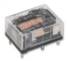
G6CU-2117P-US 12DC
Power Relay, G6C Series
⚠️ Reference pricing provided. In case of supply shortages, we will connect you with our trusted procurement partners to ensure your project's continuity.
- Manufacturer: OMRON / PARTNER STOCK
- Product type: Power Relays
- SVHC: To Be Advised
- Product Range: G6C Series
| Delivery and price | |
|---|---|
| Units per pack | 36 |
| Price | 8.4 € |
| Current stock | 25+ |
| Lead time | 30 days |
Datasheet

## **Power PCB Relay G6C**

## **SPST-NO Type Breaks 10-A Loads; SPST-NO + SPST-NC Breaks 8-A Load**

- Compact: 20 x 15 x 10 mm (L x W x H).

- Low power consumption: 200 mW.

- Semi-sealed or fully sealed construction available.

- Unique moving loop armature reduces relay size, magnetic interference, and contact bounce.

- Single and Dual coil latching types also available

- RoHS Compliant

**==> picture [99 x 19] intentionally omitted <==**

**----- Start of picture text -----**<br>
RCXVDE +E<br>**----- End of picture text -----**<br>


## **Orderin Information g**

|**Classification**|**Contact form**|**Straight Through-hole PCB**|**Straight Through-hole PCB**|**Self-clinching Through-hole PCB**|**Self-clinching Through-hole PCB**|
|---|---|---|---|---|---|
|||**Semi-sealed**|**Fully sealed**|**Semi-sealed**|**Fully sealed**|
|Non-latching|SPST-NO|**G6C-1117P-US**|**G6C-1114P-US**|**G6C-1117C-US**|**G6C-1114C-US**|
||SPST-NO + SPST-NC|**G6C-2117P-US**|**G6C-2114P-US**|**G6C-2117C-US**|**G6C-2114C-US**|
|Single coil latching|SPST-NO|**G6CU-1117P-US**|**G6CU-1114P-US**|**G6CU-1117C-US**|**G6CU-1114C-US**|
||SPST-NO + SPST-NC|**G6CU-2117P-US**|**G6CU-2114P-US**|**G6CU-2117C-US**|**G6CU-2114C-US**|
|Dual coil latching|SPST-NO|**G6CK-1117P-US**|**G6CK-1114P-US**|**G6CK-1117C-US**|**G6CK-1114C-US**|
||SPST-NO + SPST-NC|**G6CK-2117P-US**|**G6CK-2114P-US**|**G6CK-2117C-US**|**G6CK-2114C-US**|


**Note:** When ordering, add the rated coil voltage to the model number. Example: G6C-1117P-US DC12

Rated coil voltage

## **Model Number Legend**

> **G6C       -                      -      -      DC** ~~Ooogogggd a~~ **1 2 3 4 5 6 7 8**

## **1.   Relay Function**

- None:   Non-latching

- U:         Single coil latching

- K:         Dual coil latching

## **2.   Contact Form**

- 11:        SPST-NO

- 21:        SPST-NO + SPST-NC

## **3.   Contact Type**

- 1:   Standard

## **4.   Enclosure Ratings**

- 4:   Fully sealed

- 7:   Semi-sealed

## **5.   Terminals**

- P:      Straight Through-hole PCB

- C:      Self-clinching Through-hole PCB

## **6.   Approved Standards**

US:    UL/CSA certified

## **7.   Mounting Method**

None: Mount directly to PCB P6C:   Mount to Socket

**8.   Rated Coil Voltage**

- 3, 5, 6, 12, or 24 VDC

Power PCB Relay **G6C**

175

## ■ **Accessories (Order Separately)**

**Back Connecting Sockets Applicable Relay Back Connecting Socket (See note 1.)** G6C(U)-1114P-US-P6C **P6C-06P** G6C(U)-1117P-US-P6C G6C(U)-2114P-US-P6C G6C(U)-2117P-US-P6C G6CK-1114P-US-P6C **P6C-08P** G6CK-1117P-US-P6C G6CK-2114P-US-P6C G6CK-2117P-US-P6C ~~-—-~~ **Note: 1.** Not applicable to the self-clinching versions. The operating current for the socket is 5 A max. **2.** Use the G6C(U)-@@@@P-US _**-P6C**_ if mounting relays in a P6C Socket. ~~—~~

**Removal Tool P6B-Y1 Hold-down Clips P6B-C2**

## **S ecifications p**

|■**Contact Ratings**|||
|---|---|---|
|**Item**<br>**SPST-NO**<br>**SPST-NO+SPST-NC**<br>**Load**<br>Resistive load<br>(cosφ= 1)<br>Inductive load<br>(cosφ= 0.4; L/R = 7 ms)<br>Resistive load<br>(cosφ= 1)<br>Inductive load<br>(cosφ= 0.4; L/R = 7 ms)<br>**Rated load**<br>10 A at 250 VAC;<br>10A at 30 VDC<br>5 A at 250 VAC;<br>5 A at 30 VDC<br>8 A at 250 VAC;<br>8A at 30 VDC<br>3.5 A at 250 VAC;<br>3.5 A at 30 VDC<br>**Contact material**<br>AgAlloy(Cd free)<br>**Rated carry current**<br>10 A<br>8 A<br>**Max. switching voltage**<br>380 VAC, 125 VDC (the case of latching250 VAC, 125 VDC)<br>**Max. switching current**<br>10 A<br>8 A<br>**Max. switching capacity**<br>2,500 VA, 300 W<br>1,250 VA, 220 W<br>2,000 VA, 240 W<br>875 VA, 170 W<br>**Min. permissible load**<br>**(reference value - see note)**<br>10 mA at 5 VDC<br>~~SS~~|||
|**Note:**P level:λ60= 0.1 x 10⁻⁶operations|||
|■**Coil Data**|||
|**Non-latching**|||
|**Rated**<br>**voltage**<br>**(VDC)**<br>**Rated**<br>**current**<br>**(mA)**<br>**Coil**<br>**resistance**<br>**(**Ω**)**<br>**Coil inductance**<br>**(ref. value) (H)**<br>**Pick-up**<br>**voltage**<br>**Dropout**<br>**voltage**<br>**Maximum**<br>**voltage**<br>**Power**<br>**consumption**<br>**(mW)**<br>**Armature**<br>**OFF**<br>**Armature**<br>**ON**<br>**% of rated voltage**<br>3<br>67<br>45<br>0.078<br>0.067<br>70% max.<br>10% min.<br>160% max.<br>at 23°C<br>Approx. 200<br>5<br>40<br>125<br>0.22<br>0.18<br>6<br>33.30<br>180<br>0.36<br>0.29<br>12<br>16.70<br>720<br>1.32<br>1.13<br>24<br>8.30<br>2,880<br>4.96<br>4.19<br>~~Se~~|||
|**Note: 1.** The rated current and coil resistance are measured at a coil temperature of 23|The rated current and coil resistance are measured at a coil temperature of 23°C with a tolerance of±10%.||
|**2.** Operating characteristics are measured at a coil temperature of 23°C.|||


Power PCB Relay **G6C**

176

## **Single Coil Latching Type**

|**Rated**<br>**voltage**<br>**(VDC)**|**Rated**<br>**current**<br>**(mA)**|**Coil**<br>**resistance**<br>**(**Ω**)**|**Coil inductance**<br>**(ref. value) (H)**|**Coil inductance**<br>**(ref. value) (H)**|**Set**<br>**pick-up voltage**|**Reset**<br>**pick-up voltage**|**Maximum**<br>**voltage**|**Power**<br>**consumption**<br>**(mW)**|
|---|---|---|---|---|---|---|---|---|
||||**Armature**<br>**OFF**|**Armature**<br>**ON**|**% of rated voltage**||||
|3|67|45|0.09|0.06|70% max.|70% min.|160% max.<br>at 23°C|Approx. 200|
|5|40|125|0.25|0.20|||||
|6|33.30|180|0.36|0.24|||||
|12|16.70|720|1.75|1.17|||||
|24|8.30|2,880|5.83|3.84|||||


## **Dual Coil Latching Type**

|**Rated**<br>**voltage**<br>**(VDC)**|**Rated**<br>**current**<br>**(mA)**|**Coil**<br>**resistance**<br>**(**Ω**)**|**Coil inductance**<br>**(ref. value) (H)**|**Coil inductance**<br>**(ref. value) (H)**|**Coil inductance**<br>**(ref. value) (H)**|**Coil inductance**<br>**(ref. value) (H)**|**Set**<br>**pick-up**<br>**voltage**|**Reset**<br>**pick-up**<br>**voltage**|**Maximum**<br>**voltage**|**Power**<br>**consumption**<br>**(mW)**|
|---|---|---|---|---|---|---|---|---|---|---|
||||**Set Coil**||**Reset Coil**||||||
||||**Armature**<br>**OFF**|**Armature**<br>**ON**|**Armature**<br>**OFF**|**Armature**<br>**ON**|**% of rated voltage**||||
|3|93.50|32.10|0.03|0.02|0.03|0.02|70% max.|70% max.|130% max.<br>at 23°C)|Approx. 280|
|5|56|89.30|0.07|0.06|0.08|0.07|||||
|6|46.70|129|0.10|0.08|0.12|0.10|||||
|12|23.30|514|0.37|0.32|0.47|0.38|||||
|24|11.70|2,056|1.56|1.18|1.46|1.13|||||


**Note: 1.** The rated current and coil resistance are measured at a coil temperature of 23°C with a tolerance of ±10%.

**2.** Operating characteristics are measured at a coil temperature of 23°C.

**3.** The minimum pulse width of the set and reset voltage is 20 ms.

## ■ **Characteristics**

|■**Characteristics**|■**Characteristics**||
|---|---|---|
|**Contact resistance**||30 mΩmax.|
|**Operate (set) time**||10 ms max. (mean value: approx. 5 ms)|
|**Release (reset) time**||10 ms max. (mean value: approx. 2 ms; latchingtypes: mean value: approx. 5 ms)|
|**Bounce time**||5 ms max. (Approx. 3 ms typical)|
|**Min. set/reset signal width**||Latchingtype: 20 ms (at 23°C)|
|**Max. switching**<br>**frequency**|**Mechanical**|18,000 operations/hr|
||**Electrical**|1,800 operations/hr (under rated load)|
|**Insulation resistance**||1,000 MΩmin. (at 500 VDC, at 250 VDC between set coil and reset coil)|
|**Dielectric strength**||2,000 VAC, 50/60 Hz for 1 min between coil and contacts<br>2,000 VAC, 50/60 Hz for 1 min between contacts of different polarity<br>1,000 VAC, 50/60 Hz for 1 min between contacts of same polarity<br>250 VAC, 50/60 Hz for 1 min between set and reset coils (double windinglatchingtype)|
|**Surge withstand voltage**||6.000 V (1.2 x 50μs) between coil and contacts (latchingtypes: 4,500 V, 1.2 x 50μs)|
|**Vibration resistance**|**Mechanical durability**|10 to 55 Hz, 1.5-mm double amplitude|
||**Malfunction durability**|10 to 55 Hz, 1.5-mm double amplitude|
|**Shock resistance**|**Mechanical durability**|1,000 m/s2(Appox. 100G)|
||**Malfunction durability**|100 m/s2(Approx. 10G)|
|**Ambient temperature**||Operating:−25°C to 70°C (with no icing)|
|**Ambient humidity**||Operating: 5% to 85%|
|**Service Life**|**Mechanical:**|50,000,000 operations min. (at 18,000 operations/hr)|
||**Electrical:**|100,000 operations min. (at 1,800 operations/hr) See “Characteristic Data”|
|**Weight**||Approx. 5.6g|


Power PCB Relay **G6C** 177

## ■ **Approved Standards**

## **UL Recognized (File No. E41643)  - - See note**

|||**Model**||**Contact form**|||**Coil rating**|**Coil rating**|**Contact rating**|**Contact rating**|
|---|---|---|---|---|---|---|---|---|---|---|
|||G6C-1114P-US||SPST-NO||3 to 60 VDC|3 to 60 VDC||10 A, 250 VAC (general use)||
|||G6C-1114C-US|||||||10 A, 30 VDC (resistive load)||
|||G6C-1117P-US|||||||1/6 hp, 125 VAC||
|||G6C-1117C-US|||||||1/4 hp, 125 VAC||
||||||||||1/4 hp, 250 VAC||
||||||||||1/3 hp, 250 VAC||
||||||||||TV-5 (40°C, 25,000 operations)||
||||||||||600 W, 120 VAC (tungsten)||
||||||||||530 VA, 20 to 265 VAC, 2 A max. (pilot duty)||
||||||||||43.2 VA, 30 VDC (pilot duty)||
||||||||||12LRA, 2.2FLA, 30 VDC (30,000 operations)|12LRA, 2.2FLA, 30 VDC (30,000 operations)|
|||G6C-2114P-US||SPST-NO + SPST-NC|||||8 A, 250 VAC (general use)||
|||G6C-2114C–US|||||||8 A, 30 VDC (resistive load)||
|||G6C-2117P-US|||||||1/6 hp, 125 VAC||
|||G6C-2117C-US|||||||1/4 hp, 125 VAC||
||||||||||1/4 hp, 250 VAC||
||||||||||1/3 hp, 250 VAC||
||||||||||TV-5 (40°C, 25,000 operations)||
||||||||||600 W, 120 VAC (tungsten)||
||||||||||530 VA, 20 to 265 VAC, 2 A max. (pilot duty)||
||||||||||43.2 VA, 30 VDC (pilot duty)||
||||||||||12LRA, 2.2FLA, 30 VDC (30,000 operations)|12LRA, 2.2FLA, 30 VDC (30,000 operations)|
||**Note:**UL Recognition tests performed at 80°C for 6,000 operations unless otherwise specified.||||||||||
||**CSA Certified (File No. LR31928)**||**CSA Certified (File No. LR31928)**||||||||
|||**Model**<br>**Contact form**<br>G6C-1114P-US<br>G6C-1114C-US<br>G6C-1117P-US<br>G6C-1117C-US<br>SPST-NO<br>G6C-2114P-US<br>G6C-2114C-US<br>G6C-2117P-US<br>G6C-2117C-US<br>SPST-NO + SPST-NC<br> ~~pf ~~||||**Coil rating**<br>**Contact rating**<br>3 to 60 VDC<br>10 A, 250 VAC (general use)<br>10 A, 30 VDC (resistive load)<br>1/6 hp, 125 VAC<br>1/4 hp, 125 VAC<br>1/4 hp, 250 VAC<br>1/3 hp, 250 VAC<br>TV-5<br>600 W, 120 VAC (tungsten)<br>3 to 60 VDC<br>8 A, 250 VAC (general use)<br>8 A, 30 VDC (resistive load)<br>1/6 hp, 125 VAC<br>1/4 hp, 125 VAC<br>1/4 hp, 250 VAC<br>TV-5<br>600 W, 120 VAC (tungsten)<br> ~~tf~~||||||
||**VDE (Approval No. 2413) EN61810-1**||**VDE (Approval No. 2413) EN61810-1**||||||||
|||**Model**||**Contact form**||**Coil rating**|||**Contact rating**|**Number of test**|
|||||||||||**operations**|
|||G6C-1114P-US||SPST-NO|3, 12, 24 VDC|||10 A, 250 VAC (cosφ= 1)||100,000 operations|
|||G6C-1114C-US||||||5 A, 250 VAC (cosφ= 0.4)|||
|||G6C-1117P-US|||||||||
|||G6C-1117C-US|||||||||
|||G6C-2114P-US||SPST-NO + SPST-NC|Single-stable: 3, 5,|||7 A, 250 VAC (cosφ= 1)||100,000 operations|
|||G6C-2114C-US|||12, 24 VDC|||3.5 A, 250 VAC (cosφ= 0.4)|||
|||G6C-2117P-US|||Latching: 5 VDC||||||
|||G6C-2117C-US|||G6CU-2117P-VD:||||||
||||||3 VDC||||||


Power PCB Relay **G6C**

178

## **En ineerin Data g g**

## **Maximum Switching Capacity SPST-NO**

## **SPST-NO + SPST-NC**

**==> picture [352 x 311] intentionally omitted <==**

**----- Start of picture text -----**<br>
AC inductive load  AC resistive<br>(cosφ = 0.4) load AC inductive load  AC resistive load<br>(cosφ = 0.4)<br>10 a 10 : Se<br>s}——-+—+—_4# to 5-——F h OE<br>3, a—_- >TAYNT aaDNA<br>DC inductive load a AN } DC inductive load ff ft 7M} —$_N 1<br>03;osened) -—}}———| (L/R = 7 ms)loadDC resistive  +} — A onvanie—ss—i  Csa a o5-—03hidieee)— (L/R = 7 ms) 4 DC resistive load ——_—=taniecon\ a s=<br>ol,.t! 0 3.5 10| It30 50100i 3005001,000it | ott0 3.5 10|TT3050100 3005001,000A<br>Switching voltage (V) Switching voltage (V)<br>Service Life Ambient Temperature vs.<br>Maximum Coil Voltage<br>200<br>§000 (pp (pp tt<br>3000;; | [ y PT yp yyy<br>G6C-2114P-US<br>Ne 250-VAC resistive TH Joon<br>30-VDC resistive<br>BSS SS<br>we500500 RNS G6C-1114P-US250-VAC resistive250-VAC resistive ae__ 140Amin! HH<br>30-VDC resistive<br>= ONSININ - acet<br>ioSSSKOR]SSSKOR]KOR] "20 PE, :<br>ee ee 100 —<br>G6C-2114P-US G6C-1114P-US<br>250-VAC induc 250-VAC induc<br>tive (cos30-VDC inducφ = 0.4)30-VDC inducφ = 0.4)φ = 0.4) = 0.4) tive (cos30-VDC inductive φ = 0.4)30-VDC inductive φ = 0.4)φ = 0.4) = 0.4)<br>301010 tive (L/R = 7 ms) (L/R = 7 ms) 80gasPEt 304080607080| Ti tT 80<br>017234567567 8 9 1011 Ambient temperature (°C)<br>Switching current (A) Switching current (A)<br>Maximum coil voltage (%)<br>**----- End of picture text -----**<br>


**==> picture [149 x 145] intentionally omitted <==**

**----- Start of picture text -----**<br>
§000 (pp (pp tt<br>3000;; | [ y PT yp yyy<br>G6C-2114P-US<br>Ne 250-VAC resistive TH<br>30-VDC resistive<br>BSS SS<br>we500500 RNS G6C-1114P-US250-VAC resistive250-VAC resistive ae__<br>30-VDC resistive<br>= ONSININ -<br>ioSSSKOR]SSSKOR]KOR]<br>ee ee<br>G6C-2114P-US G6C-1114P-US<br>250-VAC induc 250-VAC induc<br>tive (cos30-VDC inducφ = 0.4)30-VDC inducφ = 0.4)φ = 0.4) = 0.4) tive (cos30-VDC inductive φ = 0.4)30-VDC inductive φ = 0.4)φ = 0.4) = 0.4)<br>tive (L/R = 7 ms) (L/R = 7 ms)<br>301010<br>017234567567 8 9 1011<br>Switching current (A)<br>3<br>Endurance (x10   operations)<br>**----- End of picture text -----**<br>


**Note:** The maximum coil voltage refers to the maximum value in a varying range of operating power voltage, not a continuous voltage.

Power PCB Relay **G6C**

179

## **Dimensions**

## **Note: 1.** All units are in millimeters unless otherwise indicated.

**2.** Orientation mark is indicated as follows:

## ■ **Non-latching**

**G6C-** @ **117P-US**

**==> picture [328 x 102] intentionally omitted <==**

**----- Start of picture text -----**<br>
G6C-1117P-US, G6C-1117C-US<br>20 max. 15 max. G6C-1114P-US, G6C-1114C-US<br>(19.9)* (14.9)* Terminal Arrangement/Internal<br>Connections (Bottom View)<br>10 max.<br>n 0.3 (9.9 : )* a 1 - 3 4<br>3.5<br>[ a | n f + as<br>0.65 0.9 0.5 8<br>0.9<br>PT 10.16 1.11 + 1 0.16 A<br>7.62<br>*Average value<br>**----- End of picture text -----**<br>


**G6C-** @ **117C-US**

**G6C-** @ **114P-US**

**G6C-** @ **114C-US**

**==> picture [350 x 393] intentionally omitted <==**

**----- Start of picture text -----**<br>
Mounting Holes<br>(Bottom View)<br>Tolerance: ±0.1<br>20 max. 15 max.<br>(19.9)* (14.9)* 10.16 7.62 Four, 1.1-dia. holes<br>10 max.<br>0.3 (9.9)*<br>10.16<br>3.2 3.5<br>ea - oa (2.4)<br>0.65 0.9 0.9 0.5 (1.1)<br>10.16 1.11 1 0.16<br>7.62<br>*Average value<br>G6C-2117P-US, G6C-2117C-US<br>20 max. 15 max. G6C-2114P-US, G6C-2114C-US<br>(19.9)* (14.9)* Terminal Arrangement/Internal<br>Connections (Bottom View)<br>10 max.<br>0.3 (9.9)* 1 - 3 4<br>r o 3.5 a oo<br>+<br>0.65 0.9 0.5 8 6 5<br>0.9<br>10.16 1.11 1 0.16<br>7.62<br>*Average value Mounting Holes<br>(Bottom View)<br>Tolerance: ±0.1<br>Six, 1.1-dia. holes<br>20 max. 15 max. 10.16 7.62<br>(19.9)* (14.9)*<br>10 max.<br>0.3 (9.9)* 10.16<br>(2.4)<br>3.2 i 3.5 4 1. l l<br>(1.1)<br>0.65 0.9 0.5<br>0.9<br>10.16 1.11 1 0.16<br>7.62<br>*Average value<br>**----- End of picture text -----**<br>


Power PCB Relay **G6C**

180

## ■ **Single Coil Latching**

**G6CU-** @ **117P-US**

**G6CU-1117P-US, G6CU-1117C-US G6CU-1114P-US, G6CU-1114C-US Terminal Arrangement/Internal Connections (Bottom View)** 1 − + 3 4 ~~— 5~~ SR ~~Fa~~ + − ~~e~~ 8 [ ~~"~~

**==> picture [449 x 500] intentionally omitted <==**

**----- Start of picture text -----**<br>
20 max. 15 max.<br>(19.9)* (14.9)* G6CU-1114P-US, G6CU-1114C-US<br>Terminal Arrangement/Internal<br>10 max. Connections (Bottom View)<br>0.3 (9.9)*<br>1 − + 3 4<br>ie — s 3.5 — 5<br>SR<br>| : 0.65 as 0.9 0.9 rae 0.5 Fa + − e<br>10.16 1.11 1 0.16 8<br>a 7.62 H aan [ "<br>*Average value<br>Mounting Holes<br>(Bottom View)<br>G6CU- @ 117C-US<br>20 max.(19.9)* 15 max.(14.9)* 10.16 7.62 Four, 1.1-dia. holes<br>10 max.<br>0.3 (9.9)*<br>10.16<br>3.2 3.5 (2.4)<br>NA: 0.65 0.9 re 0.5 ¢——— (1.1) =<br>0.9<br>: 10.16 7.62 1.11 an 1 0.16<br>*Average value<br>G6CU- @ 114P-US<br>20 max. 15 max. G6CU-2117P-US, G6CU-2117C-US<br>(19.9)* (14.9)* G6CU-2114P-US, G6CU-2114C-US<br>10 max. Terminal Arrangement/Internal<br>0.3 (9.9)* Connections (Bottom View)<br>3.5<br>1 - + 3 4<br>0.65 0.9 0.5<br>| 10.16 0.9 a 1.11 1 0.16 SRR F<br>7.62*Average value “ T 8 +-- oy 6 5<br>Mounting Holes<br>G6CU- @ 114C-US (Bottom View)<br>20 max. 15 max. 10.16 7.62 Six, 1.1-dia. holes<br>(19.9)* (14.9)*<br>10 max.<br>0.3 (9.9)* 10.16<br>3.2 3.5 4 © . .. (2.4)<br>(1.1) 5<br>0.65 0.9 0.5<br>0.9<br>10.16 1.11 1 0.16<br>7.62<br>*Average value<br>**----- End of picture text -----**<br>


**==> picture [109 x 65] intentionally omitted <==**

**----- Start of picture text -----**<br>
10.16 7.62 Four, 1.1-dia. holes<br>10.16<br>(2.4)<br>¢——— (1.1) =<br>**----- End of picture text -----**<br>


**G6CU-2117P-US, G6CU-2117C-US G6CU-2114P-US, G6CU-2114C-US Terminal Arrangement/Internal Connections (Bottom View)** 1 - + 3 4 SRR ~~F T~~ 8 +-- ~~oy~~ 6 5

**G6CU-** @ **114C-US**

Power PCB Relay **G6C** 181

## ■ **Dual Coil Latching**

**G6CK-** @ **117P-US**

**G6CK-** @ **117C-US**

**G6CK-** @ **114P-US**

**==> picture [182 x 382] intentionally omitted <==**

**----- Start of picture text -----**<br>
20 max. 15 max.<br>(19.9)* (14.9)*<br>_ | en<br>10 max.<br>0.3 (9.9)*<br>3.5<br>0.9<br>0.65 0.9 0.5<br>0.9<br>LL 10.16 7.62 ‘ 1.11 rd 1 0.16<br>*Average value<br>20 max. 15 max.<br>(19.9)* (14.9)*<br>10 max.<br>0.3 (9.9)*<br>3.2 3.5<br>0.65 rect 0.9 il 0.9 i 0.5 :<br>0.9<br>eo 10.16 7.62 1.11 or 1 0.16<br>*Average value<br>20 max. 15 max.<br>(19.9)* (14.9)*<br>10 max.<br>0.3 (9.9)*<br>3.5<br>0.9<br>0.65 0.9 0.5<br>0.9<br>10.16 1.11 1 0.16<br>7.62<br>*Average value<br>**----- End of picture text -----**<br>


**G6CK-1117P-US, G6CK-1117C-US G6CK-1114P-US, G6CK-1114C-US Terminal Arrangement/Internal Connections (Bottom View)**

1 2 3 4 - - S R + + 8 7 ~~i~~

## **Mounting Holes (Bottom View)**

Six, 1.1-dia. 2.5 holes 7.62 7.62 10.16 (2.4) (1.1) ~~vn~~

**G6CK-2117P-US, G6CK-2117C-US G6CK-2114P-US, G6CK-2114C-US Terminal Arrangement/Internal Connections (Bottom View)**

1 2 3 4 - - S R + + ~~ptt~~ 8 7 6 5

**G6CK-** @ **114C-US**

**==> picture [182 x 92] intentionally omitted <==**

**----- Start of picture text -----**<br>
20 max. 15 max.<br>(19.9)* (14.9)*<br>10 max.<br>0.3 (9.9)*<br>3.2 3.5<br>0.9<br>0.65 0.9 0.5<br>0.9<br>10.16 1.11 1 0.16<br>7.62<br>*Average value<br>**----- End of picture text -----**<br>


## **Mounting Holes (Bottom View)**

**==> picture [97 x 69] intentionally omitted <==**

**----- Start of picture text -----**<br>
Eight, 1.1-dia.<br>2.5 holes<br>7.62 7.62<br>10.16<br>(2.4)<br>(1.1)<br>**----- End of picture text -----**<br>


Power PCB Relay **G6C**

182

## ■ **Accessories**

**Back Connecting Sockets P6C-06P**

**Mounting Holes (Bottom View)**

**==> picture [479 x 312] intentionally omitted <==**

**----- Start of picture text -----**<br>
23.2 max.<br>(23)*<br>~ TEP]= al (2.61) 10.16 7.62 Six, 1.1-dia. holes<br>15 max.<br>(14.9)* 3.1 (2.4)<br>a ay<br>10.16<br>10.8 max. (10.6)* 7.5 (2.61) Mounting Height of Relay with Connecting Socket<br>3.5<br>— i<br>0.8 0.4<br>10.16 — 7.62 10.16 ” 17 mm max. a<br>*Average value<br>Te<br>7.5 mm max.<br>23.2 max.<br>— (23)* — Mounting Holes (Bottom View)<br>15 max. (14.9)* 3.1 (2.61) 2.547.62 7.62 Eight, 1.1-dia. holes<br>(2.4)<br>(Eateal eo<br>10.16<br>10.8 max.<br>(10.6)* 7.5 (2.61)<br>3.5<br>co Ant TY<br>0.8 0.4<br>ft 2.54 -<br>7.62 7.62 10.16<br>Note:  Rated current of socket max. 5 A<br>**----- End of picture text -----**<br>


## **P6C-08P**

*Average value

**Removal Tool P6B-Y1**

**Hold-down Clips P6B-C2**

Power PCB Relay **G6C** 183

**All sales are subject to Omron Electronic Components LLC standard terms and conditions of sale, which can be found at http://www.components.omron.com/components/web/webfiles.nsf/sales_terms.html** ~~pt~~ **ALL DIMENSIONS SHOWN ARE IN MILLIMETERS.** To convert millimeters into inches, multiply by 0.03937. To convert grams into ounces, multiply by 0.03527. ~~pT~~ OMRON. **OMRON ELECTRONIC OMRON ON-LINE COMPONENTS LLC** Global - http://www.omron.com 55 E. Commerce Drive, Suite B USA - http://www.components.omron.com Schaumburg, IL 60173 **847-882-2288**

**OMRON ON-LINE** Global - http://www.omron.com USA - http://www.components.omron.com

Printed in USA

Cat. No. X301-E-1b 09/11            Specifications subject to change without notice

Power PCB Relay **G6C**
Updated at June 4, 2026
About Novapart
Novapart is a B2B electronic component broker specialising in stock shortages and cost reduction. We source hard-to-find parts and identify compliant alternatives across a catalogue of 410,000+ components from 500+ manufacturers.
Learn more →Stock Shortage Specialist
When a component is unavailable, discontinued or has an unacceptable lead time, we tap into our network of vetted European and Asian distributors to source what you need — without compromising on quality or traceability.
Request a quote →Compliant Alternatives
We identify pin-to-pin, electrically equivalent substitutes that meet the same certifications (RoHS, AEC-Q100, REACH) as your original specification — validated against datasheets, not just part numbers. Often at a lower cost.
BOM Analysis service →