
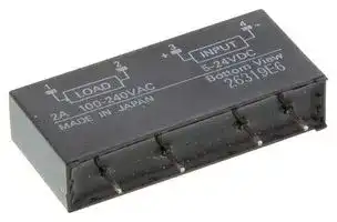


G3TB-OA202PZ DC5-24
SSR, PCB MOUNT, 264VAC, 24VDC, 2A
- Manufacturer: OMRON INDUSTRIAL AUTOMATION
- Product type:
- Conta; SSR, PCB MOUNT, 264VAC, 24VDC, 2A; Contact Configuration:-; Load Current:2A; Operating Voltage Max:264VAC; Relay Mounting:PCB; Relay Terminals:Through Hole; Switching Mode:Zero C
- SVHC: No SVHC (17-Dec-2014)
- Load Current: 2A
- Product Range: -
- Relay Mounting: PCB
- Switching Mode: Zero Crossing
- Relay Terminals: Through Hole
- Control Voltage Max: 0
- Control Voltage Min: 0
- Contact Configuration: -
- Operating Voltage Max: 264VAC
- Operating Voltage Min: 75VAC
| Delivery and price | |
|---|---|
| Units per pack | 100 |
| Price | 35.93 € |
| Current stock | 10+ |
| Lead time | 30 days |
G3TB I/O Solid State Relay

G 3 T B

## **I/O SSR Used as Interface between Logic Circuitry and Load**

- A variety of AC/DC input and output modules are classified by color.

- Operation can be monitored easily by LED indicator.

- Dielectric strength of 4,000 V between input and output terminals.

- Lineup includes models with UL and CSA certification (model numbers ending in “-US”).

Refer to "Solid State Relays Common Precautions".

## **RoHS Compliant** ~~[~~

## ■ **List of Models**

## **• Input Modules**

|Isolation|Zero cross function|Indicator|Rated output voltage|Rated input voltage|Model|Minimun<br>packingunit|
|---|---|---|---|---|---|---|
|Photocoupler|Yes|Yes|3 A at 100 to 240 VAC|5 to 24 VDC|G3TB-OA203PZ|20 pcs|
|||No||4 to 24 VDC|G3TB-OA203PZM||
||No|Yes||5 to 24 VDC|G3TB-OA203PL||
|||No||4 to 24 VDC|G3TB-OA203PLM||
||−|Yes|3 A at 5 to 48 VDC|5 to 24 VDC|G3TB-ODX03P||
|||No||4 to 24 VDC|G3TB-ODX03PM||
|||Yes|1.5 A at 48 to 200 VDC|5 to 24 VDC|G3TB-OD201P||
|||No||4 to 24 VDC|G3TB-OD201PM||


## **• Output Modules**

## ■ **Ratings**

## **• Input Module Input**

|■**Ratings**<br>**• Input Module**<br>**Input**|||||||||||||||
|---|---|---|---|---|---|---|---|---|---|---|---|---|---|---|
|Item<br>Model|Rated voltage||Operating<br>voltage|Operating||||Input<br>current|||Voltage level<br>Must operate<br>voltage<br>Must release<br>voltage||||
|G3TB-IAZR02P|100 to 240 VAC||80 to 264 VAC||||5 mA max.|5 mA max.|||80 VAC max.<br>10 VAC min.||||
|G3TB-IDZR02P|5 to 24 VDC||4 to 32 VDC||||5 mA max.|5 mA max.|||4 VDC max.|4 VDC max.<br>1 VDC min.|||
|**• Output Module**|||||||||||||||
|**Input**|||||||||||||||
|Item<br>Model|Rated<br>voltage||Operating<br>voltage||Input current|||Input current|||Voltage level<br>Must operate<br>voltage<br>Must release<br>voltage||||
|G3TB-OA203PZ|5 to 24 VDC||4 to 32 VDC||||||||4 VDC max.|4 VDC max.|||
|G3TB-OA203PZM|4 to 24 VDC||3 to 32 VDC||||||||3 VDC max.|3 VDC max.|||
|G3TB-OA203PL|5 to 24 VDC||4 to 32 VDC||||||||4 VDC max.|4 VDC max.|||
|G3TB-OA203PLM<br>G3TB-ODX03P|4 to 24 VDC<br>5 to 24 VDC||3 to 32 VDC<br>4 to 32 VDC||5 mA max.||5 mA max.||5 mA max.||3 VDC max.<br>4 VDC max.|1 VDC min.<br>3 VDC max.<br>4 VDC max.|||
|G3TB-ODX03PM|4 to 24 VDC||3 to 32 VDC||||||||3 VDC max.|3 VDC max.|||
|G3TB-OD201P|5 to 24 VDC||4 to 32 VDC||||||||4 VDC max.|4 VDC max.|||
|G3TB-OD201PM|4 to 24 VDC||3 to 32 VDC||||||||3 VDC max.|3 VDC max.|||
|**Output**|||||||||||||||
|Item|||||Applicable load||||||||||
|Model|Rated load voltage Load voltage range||||||||Load current||Load current||Inrush current||
|G3TB-OA203PZ|||||||||||||||
|G3TB-OA203PZM<br>G3TB-OA203PL<br>G3TB-OA203PLM|100 to 240 VAC<br>75 to 264 VAC||||75 to 264 VAC||||0.05 to 3 A|0.05 to 3 A||*1, 2|45 A<br>(60 Hz, 1 cycle)|*1.|
|G3TB-ODX03P<br>G3TB-ODX03PM|5 to 48 VDC||4 to 60 VDC||||||0.01 to 3 A|0.01 to 3 A||*1, 2|18 A (10 ms)|*2.|
|G3TB-OD201P<br>G3TB-OD201PM|48 to 200 VDC||40 to 200 VDC||40 to 200 VDC||||0.01 to 1.5 A|0.01 to 1.5 A||0.01 to 1.5 A *1, 2|9 A (10 ms)||


## **• Output Module Input**

## **Output**

## **Output**

|**Output**||||
|---|---|---|---|
|Item<br>Model|Logic level<br>supply voltage|Output<br>breakdown<br>voltage|breakdown<br>Output<br>current|
|G3TB-IAZR02P|4 to 32 VDC|32 VDC<br>max.|25 mA<br>max.|
|G3TB-IDZR02P|4 to 32 VDC|||


The minimum current value is measured at 10°C min.

The applicable output load current varies depending on the ambient temperature.Refer to reference data the "Load Current vs. Ambient Temperature" rating characteristic for details.

**1**

G3TB

**I/O Solid State Relay**

## ■ **Characteristics**

## **• Input Module**

|Model<br>Item|G3TB-IAZR02P|G3TB-IDZR02P|
|---|---|---|
|Operate time|20 ms max.|1 ms max.|
|Release time|20 ms max.|1 ms max.|
|Output ON<br>voltage drop|0.4 V max.||
|Leakage current|100μA max.||
|Insulation<br>resistance|100 MΩmin. (at 500 VDC)||
|Dielectric<br>strength|4,000 VAC, 50/60 Hz for 1 min between<br>input and output||
|Vibration<br>resistance|10 to 55 to 10 Hz,<br>0.75-mm single amplitude<br>(1.5mm double amplitude)||
|Shock resistance|1,000 m/s2||
|Storage<br>temperature|–30°C to 100°C<br>(with no icing or condensation)||
|Ambient<br>operating<br>temperature|–30°C to 80°C<br>(with no icing or condensation)||
|Ambient<br>operating<br>humidity|45% to 85%RH||
|Weight|Approx. 22 g||


## **• Output Module**

|Model<br>Item|G3TB-<br>OA203PZ|G3TB-<br>OA203PZM|G3TB-<br>OA203PL|G3TB-<br>OA203PLM|G3TB -<br>ODX03P|G3TB-<br>ODX03PM|G3TB -<br>OD201P|G3TB-<br>OD201PM|
|---|---|---|---|---|---|---|---|---|
|Operate time|1/2 of load power source<br>cycle + 1 ms max.||1 ms max.||0.5 ms max.||||
|Release time|1/2 of load power source cycle + 1 ms max.||||2 ms max.||||
|Output ON<br>voltage drop|1.6 V (RMS) max.||||1.6 V max.||2.5 V max.||
|Leakage current|5 mA max. (at 200 VAC)||||1 mA max.||||
|Insulation<br>resistance|100 MΩmin. (at 500 VDC)||||||||
|Dielectric<br>strength|4,000 VAC, 50/60 Hz for 1 min between input and output||||||||
|Vibration<br>resistance|10 to 55 to 10 Hz, 0.75-mm single amplitude (1.5mm double amplitude)||||||||
|Shock resistance|1,000 m/s2||||||||
|Storage<br>temperature|–30°C to 100°C (with no icing or condensation)||||||||
|Ambient<br>operating<br>temperature|–30°C to 80°C (with no icing or condensation)<br>Minimum load current: 10 to 80°C<br>Refer to the_Load Current - Ambient Temperature Rating_for the minimum load current.||||||||
|Ambient<br>operating<br>humidity|45% to 85%RH||||||||
|Weight|Approx. 32 g||||||||


**==> picture [548 x 427] intentionally omitted <==**

**----- Start of picture text -----**<br>
■ Engineering Data<br>• Load Current vs. Ambient Temperature Characteristics<br>G3TB-OA203PZ G3TB-OA203PLM<br>G G3TB-OA203PZM G3TB-ODX03P G3TB-OD201P<br>3 G3TB-OA203PL G3TB-ODX03PM G3TB-OD201PM<br>T 5  5<br>B<br>4  4  2<br>3  3  1.5<br>2  2  1<br>1  1  0.5<br>0.050.1-30 0  Minimum load current-20  0  10 20  40  60  80  100  0.010.1-30 0  Minimum load current-20  0  10 20  40  60  80  100  0.010.1-30 0  Minimum load current-20  0  10 20  40  60  80  100<br>Ambient temperature (°C)  Ambient temperature (°C)  Ambient temperature (°C)<br>• One Cycle Surge Current: Non-repetitive Non-repetitive (Keep the inrush current to half the rated value if it occurs repetitively.)<br>G3TB-OA203PZ G3TB-OA203PL G3TB-ODX03P G3TB-OD201P<br>G3TB-OA203PZM G3TB-OA203PLM G3TB-ODX03PM G3TB-OD201PM<br>50 30 15<br>28 14<br>26 13<br>24 12<br>40<br>22 11<br>20 10<br>30 18 9<br>16 8<br>14 7<br>20 12 6<br>10 5<br>8 4<br>10 6 3<br>4 2<br>2 1<br>0 0 0<br> 10  30 50 100 200  500 1,000  5,000  10  30 50  100  300 500 1,000     3,000  10  30 50  100  300 500 1,000  3,000<br>Energized time (ms) Energized time (ms) Energized time (ms)<br>Load current (A)  Load current (A)  Load current (A)<br>Inrush current (A. Peak) Inrush current (A. Peak) Inrush current (A. Peak)<br>**----- End of picture text -----**<br>


**2**

G3TB

**I/O Solid State Relay**

G 3 T B

■ **Circuit Configuration**

**==> picture [333 x 229] intentionally omitted <==**

**----- Start of picture text -----**<br>
Type Model Case color Indicator Circuit<br>AC input G3TB-IAZR02P Yellow Yes<br>nel<br>DC input G3TB-IDZR02P White Yes<br>G3TB-OA203PZ<br>Yes<br>G3TB-OA203PL<br>AC output Black<br>G3TB-OA203PZM<br>No<br>G3TB-OA203PLM<br>G3TB-ODX03P<br>Yes<br>G3TB-OD201P<br>DC output Red<br>G3TB-ODX03PM<br>No<br>G3TB-OD201PM<br>circuit<br>Rectification circuit Constant-current Amplification circuit<br>circuit<br>Constant-current Amplification circuit<br>circuit<br>Drive circuit<br>Constant-current Zero-cross circuit<br>circuit<br>Constant-currentRectification circuit Amplification circuit<br>**----- End of picture text -----**<br>


**• Example of Logic Output Circuit**

**==> picture [498 x 122] intentionally omitted <==**

**----- Start of picture text -----**<br>
Example 1. G3TB-I Example 2. G3TB-I<br>4 to 32 VDC<br>+3<br>si c +3 SW (+) = 3.3K<br>SW (+) 3.3K<br>4<br>4 Example: Relay with  4 to 32 VDC<br>(−) built-in inrush<br>= (−) Lo −5 absorption diode<br>−5<br>Note: AC- and DC-input versions are available.<br>Logic circuitry<br>Note: AC- and DC-input versions are available.<br>Load<br>or CPU<br>Sequential circuit<br>**----- End of picture text -----**<br>


## ■ **Dimensions**

(Unit: mm)

**Input SSR G3TB-I**

**==> picture [496 x 174] intentionally omitted <==**

**----- Start of picture text -----**<br>
PCB Dimensions  (Bottom View)<br>G3TB-I 2.54 Five, 1.3-dia. holes<br>2.54 es s FOUSTESTSTSESDEEaE<br>10 max.<br>SeA! EEEESE Eee<br>20.5 max. 6.05 5.08 5.08<br>23.2 10.16 12.7<br>ee Te C ECE Terminal Arrangement  ;EC (Bottom View)<br>6.05 [±0.1] 0.8 External input Output External input Output<br>10.16 [±0.1] 6.6 1 2 3 4 5 1 2 3 4 5<br>22.8627.94 [±0.1][±0.1] 0.6 + − + − ~ ~ + −<br>33.02 [±0.1] Vcc Vcc<br>4 3.5 max.<br>Load Load<br>Logic circuit Logic circuit<br>**----- End of picture text -----**<br>


**3**

G3TB

**I/O Solid State Relay**

G 3 T B

## **Output SSR G3TB-I**

**==> picture [471 x 220] intentionally omitted <==**

**----- Start of picture text -----**<br>
PCB Dimensions  (Bottom View)<br>2.54 Four, 1.2-dia. holes<br>SN a20000000000a  000000 008<br>2.54<br>Ss 1 | ) PTH TT Pe ee eee tA Ty<br>igi S/SeaneRaeeenanaenlie<br>+ 5 10 max. Lee eee eee eee f<br>oe LIT TLEETTITTT TET tT ttt ttt<br>6.05 5.08<br>10.16 12.7<br>29.5 Terminal Arrangement  (Bottom View)<br>30.5 max.<br>33.2 External AC output Logic input External DC output Logic input<br>1 2 3 4 1 2 3 4<br>~ ~ + − + − + −<br>Ei Ti | a f |<br>6.05 [±0.1]<br>10.1622.86 [±0.1] | [±0.1] | 0.8 6.6 O Z2 © O oO<br>27.94 [±0.1] 0.6 t--<br>rhs °<br>4 3.5 max. a8 Z1<br>tT |<br>bye<br>Note. Connect the varistor to  Note. Connect the diode in<br>the Z1 or Z2. parallel with the load.<br>Load Load<br>**----- End of picture text -----**<br>


## ■ **Safety Precautions**

- **Please refer to “Solid State Relays Common Precautions” for correct use.**

## **Precautions for Correct Use**

- SSR for I/O classification by the color is as follows:

**==> picture [477 x 197] intentionally omitted <==**

**----- Start of picture text -----**<br>
G3TB-IAZR02P Yellow<br>AC equipment 100 to 240 VAC 5 to 24 VDC<br>AC input module<br>G3TB-IDZR02P White<br>DC equipment 5 to 24 VDC 5 to 24 VDC<br>DC input module<br>G3TB-OA203PZ<br>G3TB-OA203PZM Black PLC or logic<br>AC equipment 100 to 240 VAC 3 A G3TB-OA203PL 5 to 24 VDC (4 to 24 VDC) circuitry<br>G3TB-OA203PLM<br>AC output module<br>G3TB-ODX03P<br>G3TB-ODX03PM<br>Red<br>DC equipment 4 to 60 VDC/40 to 200 VDC 3 A * G3TB-OD201P 5 to 24 VDC (4 to 24 VDC)<br>* G3TB-OD201PM<br>* With 1.5-A output.<br>DC output module<br>When mounting more than one output  Output module<br>5 mm min.<br>**----- End of picture text -----**<br>


- When mounting more than one output module, make a distance of 5 mm minimum between adjacent SSRs. Up to 16-point, 3-A load switching is possible.

**4**

G3TB

**I/O Solid State Relay**

G 3 T B

- Application examples provided in this document are for reference only. In actual applications, confirm equipment functions and safety before using the product.

- Consult your OMRON representative before using the product under conditions which are not described in the manual or applying the product to nuclear control systems, railroad systems, aviation systems, vehicles, combustion systems, medical equipment, amusement machines, safety equipment, and other systems or equipment that may have a serious influence on lives and property if used improperly. Make sure that the ratings and performance characteristics of the product provide a margin of safety for the system or equipment, and be sure to provide the system or equipment with double safety mechanisms.

**Note: Do not use this document to operate the Unit.**

**OMRON Corporation Electronic and Mechanical Components Company**

**Contact:  www.omron.com/ecb**

**Cat. No. K077-E1-05** 1014(0207)(O)

**5**
Updated at June 10, 2026
With a legacy spanning over 80 years, Omron Industrial Automation is a globally recognized leader in the manufacture of advanced industrial control and automation components. Renowned for their reliability and engineering excellence, Omron delivers comprehensive solutions that enhance efficiency, machine safety, and precision across a wide range of manufacturing environments. Our extensive portfolio of Omron products is heavily focused on their industry-leading sensing and switching technologies. We offer a vast selection of sensors, excelling specifically in high-performance proximity sensors, light sensors, and temperature sensors. Complementing this range are robust switching solutions, featuring a deep inventory of power relays, solid-state relays, safety relays, and essential relay accessories designed for demanding operational requirements. Beyond sensing and switching, Omron is highly regarded for its precision automation and process control equipment. Our selection features highly accurate temperature controllers, versatile process controllers, and sophisticated panel displays and instrumentation. To support these fundamental systems, we also supply dependable Omron power supplies, notably AC/DC converters, alongside vital connectivity components like DIN rail terminal blocks to ensure secure, efficient, and complete industrial setups.
About Novapart
Novapart is a B2B electronic component broker specialising in stock shortages and cost reduction. We source hard-to-find parts and identify compliant alternatives across a catalogue of 410,000+ components from 500+ manufacturers.
Learn more →Stock Shortage Specialist
When a component is unavailable, discontinued or has an unacceptable lead time, we tap into our network of vetted European and Asian distributors to source what you need — without compromising on quality or traceability.
Request a quote →Compliant Alternatives
We identify pin-to-pin, electrically equivalent substitutes that meet the same certifications (RoHS, AEC-Q100, REACH) as your original specification — validated against datasheets, not just part numbers. Often at a lower cost.
BOM Analysis service →