
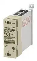


G3PA-240B-VD DC5-24
Solid State Relay, 40 A, 30 VDC, DIN Rail, Screw, Zero Crossing
- Manufacturer: OMRON INDUSTRIAL AUTOMATION
- Product type:
- Contact Configuration:-; Load Current:40A; Relay Mounting:DIN Rail; Relay Terminals:Screw; Operating Voltage Min:4VDC; Operating Voltage Max:30VDC; Control Voltage Min:24VAC; Control Volta
- Load Current: 40A
- Product Range: G3PA Series
- Relay Mounting: DIN Rail
- Switching Mode: Zero Crossing
- Relay Terminals: Screw
- Control Voltage Max: 240VAC
- Control Voltage Min: 24VAC
- Contact Configuration: -
- Operating Voltage Max: 30VDC
- Operating Voltage Min: 4VDC
| Delivery and price | |
|---|---|
| Units per pack | 10 |
| Price | 80.29 € |
| Current stock | 10+ |
| Lead time | 30 days |
## **Solid State Relays G3PA**

## **Extremely Thin Relays Integrated with Heat Sinks**

- Downsizing achieved through optimum design of heat sink.

- Mounting possible via screws or via DIN track.

- Close mounting possible for linking terminals. (Except for G3PA-260B-VD and G3PA-450B-VD-2.)

- Applicable with 3-phase loads.

- Replaceable power element cartridges.

- Complies with VDE 0160 (finger protection), with a dielectric strength of 4,000 V between input and load.

- Complies with VDE 0805, IEC 950.

- Certified by UL, CSA, and VDE (reinforced insulation).

## **Orderin Information g**

## **List of Models**

To Order: Select the part number and add the rated input voltage range. (e.g., G3PA-430B-VD-2 _DC12-24_ )

|**Isolation**<br>~~aOo~~|**Zero cross function**<br>~~Oo~~|**Indicator**|**Rated output load**<br>~~=~~|**Rated input voltage**|**Model**|
|---|---|---|---|---|---|
|Phototriac<br>coupler<br>~~a~~ ~~Oo~~|Yes<br>~~Oo~~|Yes<br>|10 A at 24 to 240 VAC<br>~~=~~|5 to 24 VDC|**G3PA-210B-VD**|
||||20 A at 24 to 240 VAC<br>~~=~~||**G3PA-220B-VD**|
||||40 A at 24 to 240 VAC<br>~~=~~||**G3PA-240B-VD**|
||||60 A at 24 to 240 VAC<br>~~=~~||**G3PA-260B-VD**|
||No<br>~~Oo~~||10 A at 24 to 240 VAC<br>~~=~~||**G3PA-210BL-VD**|
||||20 A at 24 to 240 VAC||**G3PA-220BL-VD**|
||||40 A at 24 to 240 VAC||**G3PA-240BL-VD**|
||||60 A at 24 to 240 VAC||**G3PA-260BL-VD**|
||Yes<br>~~_ ~~||10 A at 24 to 240 VAC<br>~~—~~|24 VAC|**G3PA-210B-VD**|
||||20 A at 24 to 240 VAC<br>~~—~~||**G3PA-220B-VD**|
||||40 A at 24 to 240 VAC<br>~~—~~||**G3PA-240B-VD**|
||||60 A at 24 to 240 VAC<br>~~—~~||**G3PA-260B-VD**|
||||20 A at 180 to 400 VAC<br>~~—~~|12 to 24 VDC|**G3PA-420B-VD**|
||||30 A at 180 to 400 VAC<br>~~—~~||**G3PA-430B-VD**|
||||20 A at 200 to 480 VAC<br>~~—~~||**G3PA-420B-VD-2**|
||||30 A at 200 to 480 VAC<br>~~—~~||**G3PA-430B-VD-2**|
||||50 A at 200 to 480 VAC<br> ~~—~~||**G3PA-450B-VD-2**|


Solid State Relays **G3PA** 455

|**Name**<br>~~==~~|**Carry current**<br>~~==~~|**Load voltage range**<br>~~==~~|**Applicable SSR**<br>~~==~~|**Model**<br>~~==~~|**VDE**<br>**certification**<br>~~==~~|
|---|---|---|---|---|---|
|Power Device<br>Cartridge<br>~~==~~|10 A<br>~~==~~|19 to 264 VAC<br>~~==~~|G3PA-210B-VD DC5-24<br>~~==~~|**G32A-A10-VD DC5-24**<br>~~==~~|Yes<br>~~==~~|
||||G3PA-210BL-VD DC5-24<br>~~==~~|**G32A-A10L-VD DC5-24**<br>~~==~~||
||||G3PA-210B-VD AC24<br>~~==~~|**G32A-A10-VD AC24**<br>~~==~~||
||20 A<br>~~==~~||G3PA-220B-VD DC5-24<br>~~==~~|**G32A-A20-VD DC5-24**<br>~~==~~||
||||G3PA-220BL-VD DC5-24|**G32A-A20L-VD DC5-24**||
||||G3PA-220B-VD AC24|**G32A-A20-VD AC24**||
||40 A||G3PA-240B-VD DC5-24|**G32A-A40-VD DC5-24**||
||||G3PA-240BL-VD DC5-24|**G32A-A40L-VD DC5-24**||
||||G3PA-240B-VD AC24|**G32A-A40-VD AC24**||
||60 A||G3PA-260B-VD DC5-24|**G32A-A60-VD DC5-24**||
||||G3PA-260BL-VD DC5-24|**G32A-A60L-VD DC5-24**||
||||G3PA-260B-VD AC24|**G32A-A60-VD AC24**||
||20 A|150 to 440 VAC|G3PA-420B-VD DC12-24|**G32A-A420-VD DC12-24**||
||30 A||G3PA-430B-VD DC12-24|**G32A-A430-VD DC12-24**||
||20 A|180 to 528 VAC|G3PA-420B-VD-2 DC12-24|**G32A-A420-VD-2 DC12-24**||
||30 A||G3PA-430B-VD-2 DC12-24|**G32A-A430-VD-2 DC12-24**||
||50 A||G3PA-450B-VD-2 DC12-24|**G32A-A450-VD-2 DC12-24**||


## **S ecifications p**

■ **Ratings (at an Ambient Temperature of 25** ° **C) Input Model Rated voltage Operating Voltage Input current Voltage level range impedance Must operate voltage Must release voltage** G3PA-2❏❏B-VD 5 to 24 VDC 4 to 30 VDC 7 mA max. 4 VDC max. 1 VDC min. G3PA-2❏❏BL-VD 20 mA max. G3PA-2❏❏B-VD 24 VAC 19.2 to 26.4 VAC 1.4 kΩ±20% 19.2 VAC max. 4.8 VAC min. ~~a~~ G3PA-4❏❏B-VD(-2) 12 to 24 VDC 9.6 to 30 VDC 7 mA max. 9.2 VDC max. 1 VDC min. **Output Model Applicable load Rated load voltage Load voltage range Load current Inrush current** G3PA-210B(L)-VD 24 to 240 VAC (50/60 Hz) 19 to 264 VAC (50/60 Hz) 0.1 to 10 A 150 A (60 Hz, 1 cycle) G3PA-220B(L)-VD 0.1 to 20 A 220 A (60 Hz, 1 cycle) G3PA-240B(L)-VD 0.5 to 40 A 440 A (60 Hz, 1 cycle) G3PA-260B(L)-VD 0.5 to 60 A 440 A (60 Hz, 1 cycle) G3PA-420B-VD 180 to 400 VAC (50/60 Hz) 150 to 440 VAC (50/60 Hz) 0.5 to 20 A 220 A (60 Hz, 1 cycle) G3PA-430B-VD 0.5 to 30 A 440 A (60 Hz, 1 cycle) G3PA-420B-VD-2 200 to 480 VAC (50/60 Hz) 180 to 528 VAC (50/60 Hz) 0.5 to 20 A 220 A (60 Hz, 1 cycle) G3PA-430B-VD-2 0.5 to 30 A 440 A (60 Hz, 1 cycle) ~~——~~ G3PA-450B-VD-2 0.5 to 50 A 440 A (60 Hz, 1 cycle) Refer to _Engineering Data_ for further details.

Solid State Relays **G3PA**

456

■ **Characteristics**

**Item G3PAG3PAG3PAG3PAG3PAG3PAG3PAG3PAG3PA-** ~~A~~ **210B(L)-VD 220B(L)-VD 240B(L)-VD 260B(L)-VD 420B-VD 420B-VD-2 430B-VD 430B-VD-2 450B-VD-2** Operate time 1/2 of load power source cycle + 1 ms max. (DC Input, -B models) 1 1/2 of load power source cycle + 1 ms max. (AC Input) 1 ms max. (-BL models) Release time 1/2 of load power source cycle + 1 ms max. (DC Input) ~~a~~ 1 1/2 of load power source cycle + 1 ms max. (AC Input) Output ON 1.6 V (RMS) max. 1.8 V (RMS) max. voltage drop Leakage 5 mA max. (at 100 VAC) 10 mA max. (at 100 VAC) 20 mA 20 mA max. (at 20 mA 20 mA max. (at 480 VAC) current 10 mA max. (at 200 VAC) 20 mA max. (at 200 VAC) max. (at 480 VAC) max. (at ~~a~~ 400 VAC) 400 VAC) I[2] t 260 A[2] s 1,260 A[2] s 260 A[2] s 1,800 A[2] s 1,800 A[2] s 1,800 A[2] s ~~pOee~~ Insulation 100 MΩ min. (at 500 VDC) resistance ~~a~~ Dielectric 4,000 VAC, 50/60 Hz for 1 min ~~a~~ strength Vibration Malfunction: 10 to 55, 0.75–mm double amplitude (Mounted to DIN track) resistance ~~a~~ Shock Malfunction: 300 m/s[2] (mounted to DIN track) resistance ~~a~~ Ambient Operating:–30°C to 80°C (with no icing or condensation) temperature Storage:–30°C to 100°C (with no icing or condensation) Certified UL, CSA, EN60950 File No. 5915ÜG UL, CSA , UL, CSA, UL, CSA, UL, CSA, EN60947-4-3 File standards EN60947EN60947-4-3 EN60947No. 133127ÜG 4-3 File File No. 4-3 File No. 133127ÜG No. 6642ÜG 6642ÜG ~~pf~~ Ambient Operating: 45% to 85% ~~a~~ humidity Weight Approx. Approx. Approx. Approx. Approx. Approx. Approx. Approx. Approx. ~~rr~~ 260 g 340 g 460 g 900 g 290 g 290 g 410 g 410 g 900 g

Solid State Relays **G3PA** 457

## **O eration p**

## ■ **Replacement Parts**

## **- G32A A Power Device Cartridge**

The G32A-A Power Device Cartridge (a Triac Unit) can be replaced with a new one. When the temperature indicator has changed from pink to red, the triac circuitry may have malfunctioned possibly by an excessive flow of current, in which case, dismount the damaged cartridge for replacement.

The damaged cartridge can be replaced with a new one without disconnecting the wires from the G3PA.

Improve the heat radiation efficiency of the G3PA before replacing the cartridge.

The G32A-A Power Device Cartridge can withstand an excessive current for a short period of time, such as may be caused accidentally by the short circuitry of the load, in which case the temperature indicator will not turn red.

Be sure to turn OFF the power supply when replacing the Cartridge. Supplying power with the Cartridge removed may result in malfunction.

## **Appearance**

**==> picture [329 x 10] intentionally omitted <==**

**----- Start of picture text -----**<br>
G32A-A10(L)-VD G32A-A20(L)-VD G32A-A40(L)-VD G32A-A60(L)-VD<br>**----- End of picture text -----**<br>


**==> picture [268 x 10] intentionally omitted <==**

**----- Start of picture text -----**<br>
G32A-A420-VD(-2) G32A-A430-VD(-2) G32A-A450-VD-2<br>**----- End of picture text -----**<br>


## **Replacing Power Device Cartridges**

When replacing Power Device Cartridges, use the specified model. Using a Power Device Cartridge other than the specified one will result in faulty operation and destruction of the elements.

Solid State Relays **G3PA**

458

## ■ **Replacement Procedure**

## **- - - - - - - G32A A10(L) VD/G32A A20(L) VD/G32 A420 VD( 2)**

Use the special tool (provided) to extract the cartridge for replacement with a new one.

## **Extraction**

Follow the procedures below to remove the Power Device Cartridge from the G3PA.

**1. Switch off the power.**

**2.** Remove the terminal cover.

**3.** Hook the indented part of the cartridge with the tool (supplied with a new  cartridge) and pull up on the cartridge to remove it.

**==> picture [62 x 30] intentionally omitted <==**

**----- Start of picture text -----**<br>
Remover<br>Hook here with<br>Remover.<br>**----- End of picture text -----**<br>


**==> picture [85 x 7] intentionally omitted <==**

**----- Start of picture text -----**<br>
Apply silicone grease here.<br>**----- End of picture text -----**<br>


**2.** Make sure that there is no dust or pieces of wire on the heat sink of the G32A-A or the G3PA.

**3.** Insert the cartridge into the opening of the G3PA so that the letters on the cartridge and those on the G3PA are in the same direction and side A and side B are even.

**==> picture [115 x 32] intentionally omitted <==**

**----- Start of picture text -----**<br>
Side A<br>Side B<br>**----- End of picture text -----**<br>


## **Installation**

Follow the procedures below to Install the Power Device Cartridge on the G3PA.

**1.** Apply silicone grease (provided with the G32A-A) to the entire surface of the heat sink.

**4.** Attach the terminal cover.

**5.** Switch on the power and check the G3PA to be sure it works properly.

## **G32A-A40(L)-VD/G32A-A60(L)-VD/G32A-A430-VD(-2)/G32A-A450-VD-2**

The G32A Power Device Cartridge is mounted and secured with screws to the G3PA Unit.

## **Extraction**

Follow the procedures below to remove the G32A-A Power Device Cartridge from the G3PA.

**1. Switch off the power** .

## **Installation**

Follow the procedures below to Install the Power Device Cartridge on the G3PA.

   **1.** Apply silicone grease to the entire surface of the heat sink.

**2.** Remove the terminal cover.

**3.** Loosen the two centered screws on the sides to dismount the cartridge. The screws are connected to terminals 1 and 2.

**==> picture [131 x 40] intentionally omitted <==**

**----- Start of picture text -----**<br>
Loosen<br>eS |<br>Loosen<br>**----- End of picture text -----**<br>


Apply silicone grease here.

   **2.** Make sure that there is no dust or pieces of wire on the heat sink of the G32A-A or the G3PA.

**4.** Loosen the screws on both the corners.

**==> picture [124 x 40] intentionally omitted <==**

**----- Start of picture text -----**<br>
Loosen<br>Loosen<br>**----- End of picture text -----**<br>


**5.** Hold the indented part of both the corners to remove the cartridge.

Solid State Relays **G3PA** 459

**3.** Insert the cartridge into the opening of the G3PA so that side A and side B are even.

**4.** Tighten the screws on both the corners with a tightening torque of 0.59 to 0.78 N•m.

**5.** Tighten the screws on both the sides with a tightening torque of 0.59 to 0.78 N•m.

**==> picture [21 x 52] intentionally omitted <==**

**----- Start of picture text -----**<br>
Side A<br>Side B<br>**----- End of picture text -----**<br>


**6.** Attach the terminal cover.

**7.** Switch on the power and check the G3PA to be sure it works properly.

## ■ **Linking Terminal Connection**

- Connecting with linking terminal for G3PA-210B(L)-VD, -220B(L)VD, -240B(L)-VD and G3PA-420B-VD(-2), G3PA-430B-VD(-2).

- Connecting with linking terminal to “G32A-D” series short circuit unit. (Order short circuit units seperately.)

**==> picture [547 x 424] intentionally omitted <==**

**----- Start of picture text -----**<br>
SSR1 SSR2 SSR1 SSR2 SSR G32A Unit SSR G32A Unit<br>| 2) NEw<br>a O mH O CJ = \ *<br>* The cover will not fit if<br>1.   When SSRs are close  2.   Insert the linking  the terminal protrudes.<br>mounted, loosen the M3.5 Sems screw and  terminal securely into the center of  1.   When SSR are close  2.   Insert the linking terminal<br>down.flip the linking terminal  the screw and tighten the screw. mounted, loosen the M3.5 Sems screw on the G32A and flip the  the screw. Ensure that securely into the center of the screw and tighten<br>linking terminal down. the linking terminal does<br>not protrude.<br>|<br>© 7 O i"|<br>Connect the terminal with power off. o omron O 7 Te<br>Linking terminal G3PA-420B-VD Linking<br>| terminal<br>Refer to the instruction manual for<br>the G32A-A Power Device Cartridge<br>to replace the G3PA's triac part.<br>Linking<br>Linking terminal terminal<br>ellS| oO7 Oo| Sgi<br>When the temperature indicator has turned from pink to red, the G32-A-A Power Device Cartridge  Use the terminal cover to prevent accidents<br>may have malfunctioned, in which case the cartridge must be replaced with a new one. due to electric shock.<br>**----- End of picture text -----**<br>


Solid State Relays **G3PA**

460

**En ineerin Data g g**

## **Load Current vs. Ambient Temperature**

## **Vertical Mounting**

**==> picture [74 x 9] intentionally omitted <==**

**----- Start of picture text -----**<br>
Panel<br>Ground<br>**----- End of picture text -----**<br>


**==> picture [486 x 324] intentionally omitted <==**

**----- Start of picture text -----**<br>
G3PA-210B(L)-VD, G3PA-220B(L)-VD G3PA-240B(L)-VD G3PA-260B(L)-VD<br>*<br>x)<br>25 G3PA-220B(L)-VD s are 80 *<br>*<br>s<br>s<br>60<br>G3PA-210B(L)-VD<br>15 ~ = ~<br>108 nae = q \ 16 \ 4025<br>10 20<br>0 0 )<br>-30-20 0 20 40 60 80 100 —30-20 0 20 40 60 80 100 -30 -20 0 20 40 60 80 100<br>Ambient temperature (°C) Ambient temperature (°C) Ambient temperature (°C)<br>G3PA-420B-VD, G3PA-420B-VD-2 G3PA-430B-VD, G3PA-430B-VD-2 G3PA-450B-VD-2<br>|<br>| ° Tt tT tt<br>|<br>: ° | | |tt<br>x 1 ys Lf | .FE | tT | | |<br>| G3PA-420B \ 30 50 \<br>| \ 20 ‘ . "TL30TINE[I<br>‘ !! | PEttet AL<br>F 12 -4-7---<br>| | ‘ | 10a eees<br>| 1 0 0<br>—300 —20 0 20EF30 40 60 80 100 —30 —20 0 20 30 40 60 80 100 —30-20Li |0 20tet}30 40 |60 |80 100<br>Ambient temperature (°C) Ambient temperature (°C) Ambient temperature (°C)<br>Load current (A) Load current (A) Load current (A)<br>Load current (A) Load current (A) Load current (A)<br>**----- End of picture text -----**<br>


**Note:** Close mounting is possible for a maximum of three Units by reducing the load current by 20%. (A minimum clearance of 10 mm must be provided when mounting four or more Units.)

Solid State Relays **G3PA** 461

**Input Voltage vs. Input Current**

**==> picture [374 x 174] intentionally omitted <==**

**----- Start of picture text -----**<br>
G3PA-2 @ 0B-VD G3PA-4 @0 -VD, G3PA-4 @ -VD-2<br>8 eSSS Ta = 25 ° C 108 T = 25°C a<br>6 —_ 6 ===:<br>4 4 Input<br>fhre fieNe Input current UY eeee current aY | [|]<br>2 2<br>Input impedance<br>Ve eae<br>1 1<br>0.8 Input impedance 0.8<br>0.6 ——stA eee 0.6 aa ee ee a Pett} _f _{ {|<br>0.4 |aeSef S| | Ld PTT 0.4 eea es eeeeeee<br>0.2 0.2<br>0.1 0.1<br>1 2 4 6 8 10 20 40 1 2 4 6 8 10 20 40<br>Input voltage (V) Input voltage (V)<br>)Ω )Ω<br>Input current (mA) Input current (mA)<br>Input impedance (k Input impedance (k<br>**----- End of picture text -----**<br>


## **Horizontal Mounting**

**==> picture [44 x 29] intentionally omitted <==**

**----- Start of picture text -----**<br>
Panel<br>eee<br>Ground<br>**----- End of picture text -----**<br>


**==> picture [486 x 333] intentionally omitted <==**

**----- Start of picture text -----**<br>
G3PA-210B(L)-VD, G3PA-220B(L)-VD G3PA-240B(L)-VD G3PA-260B(L)-VD<br>G3PA-220B(L)-VD x<br>20 60<br>28<br>15 [ a -———| -<br>14 ee 50 E e 42<br>11 G3PA-210B(L)-VD 40<br>10 ewa NEL] =TT TN | aS=<br>75.55 ee 1110 TLCCDN 1820 :<br>3.5<br>—300 Ses —20 sry 0 20 40 60 80 100| —300TEE]—20 0 20 40 60 80 100| = 0 − CESS FEL 30 −20 0 20 Ed 40 60 80 100<br>Ambient temperature (°C) Ambient temperature (°C) Ambient temperature (°C)<br>G3PA-420B-VD, G3PA-430B-VD  G3PA-450B-VD-2<br>G3PA-420B -VD-2, G3PA-430B-VD-2<br>rT] id “To [ [|<br>+ Yt Tt ft tf<br>p h [tl<br>= G3PA-430B-VD M S] P| | | | | ff<br>20 eee NI| RRR<br>ic an ee<br>G3PA-420B-VD<br>14 T X ot}<br>yt .! [L] tT [N][ Nn] owt |LENTNE T T L<br>° CESPe PEPE| whtLIN<br>Ambient temperature (°C) Ambient temperature (°C)<br>Load current (A) Load current (A) Load current (A)<br>Load current (A) Load current (A)<br>**----- End of picture text -----**<br>


Solid State Relays **G3PA**

462

## **Close Mounting (Up to Three)**

**==> picture [74 x 59] intentionally omitted <==**

**----- Start of picture text -----**<br>
Panel<br>Ground<br>OL [H] olH°<br>H6<br>° ° fe}<br>[e} [e}<br>DIN track<br>**----- End of picture text -----**<br>


**==> picture [486 x 362] intentionally omitted <==**

**----- Start of picture text -----**<br>
G3PA-210B(L)-VD, G3PA-220B(L)-VD G3PA-240B(L)-VD G3PA-260B(L)-VD<br>30<br>45<br>27<br>40<br>64<br>36<br>x<br>2018 G3PA-220B-VD Hl 30 ——— ea ALLEL<br>15 48 x<br>13 HPAL 20 Ps 40 CEL<br>" G3PA-210B-VD Nor] ELE LEAL | REPS<br>9 14<br>7 10 20<br>5 SIN eee eee<br>4.5<br>aaaaae | PEELE<br>—30 —20 0 20 40 60 80 100 —30 —20 0 20 40 60 80 100 -30 -20 0 20 40 60 80 100<br>Ambient temperature (°C) Ambient temperature (°C) Ambient temperature (°C)<br>G3PA-420B-VD, G3PA-420B-VD-2 G3PA-430B-VD, G3PA-430B-VD-2<br>30 40<br>30<br>20<br>24<br>16<br>20<br>10 aNTEN ;TN<br>10<br>−30 10 30 80 100 −30 10 30 80<br>Ambient temperature (°C) Ambient temperature (°C)<br>G3PA-450B-VD-2<br>Load current (A) Load current (A) Load current (A)<br>Load current (A) Load current (A)<br>**----- End of picture text -----**<br>


**==> picture [146 x 128] intentionally omitted <==**

**----- Start of picture text -----**<br>
TT<br>50 PP [PRE] y<br>TT TIN<br>20 ~ N<br>cose<br>Wet30220 0 20 30ET40 60 80<br>Ambient temperature (°C)<br>Load current (A)<br>**----- End of picture text -----**<br>


Solid State Relays **G3PA** 463

## **Inrush Current Resistivity**

One cycle, non-repetitive (Keep the inrush current to half the rated value if it occurs repetitively.)

**==> picture [446 x 187] intentionally omitted <==**

**----- Start of picture text -----**<br>
G3PA-210B(L)-VD G3PA-220B(L)-VD, G3PA-420B-VD,<br>G3PA-420B-VD-2<br>G3PA-450B-VD-2<br>,NIL L|||: 200 NEE :<br>‘NN = aK<br>THT)  “<br>on 30 50 100200 500 1,000 5,000 10 30 50 100 200 500 1,000 5,000 aT 30 50 100 200 500 1,000<br>Energized time (ms) Energized time (ms) Energized time (ms)<br>Inrush current (A. Peak) Inrush current (A. Peak) Inrush current (A. Peak)<br>**----- End of picture text -----**<br>


**G3PA-240B(L)-VD/260B(L)-VD, G3PA-430B-VD, G3PA-430B-VD-2, G3PA-450B-VD-2**

Solid State Relays **G3PA**

464

## **Dimensions**

## **Note:** All units are in millimeters unless otherwise indicated.

**==> picture [78 x 10] intentionally omitted <==**

**----- Start of picture text -----**<br>
G3PA-210B(L)-VD<br>**----- End of picture text -----**<br>


**==> picture [383 x 154] intentionally omitted <==**

**----- Start of picture text -----**<br>
Without Terminal   With Terminal<br>Cover Cover Mounting   Terminal<br>4.6 dia. Holes Arrangement/<br>Two, M4 Internal Connections<br>Linking terminal B1<br>A]_{0] 1|  71st| peter t ) J Two, 4.5 dia. or M4 holes<br>i can ae al ocd<br>| ES Two,  | | | q | Ii | | H +@!<br>9 1 M3.5 38 W w027—4 4 | — : i |<br>| aaaJ 1| | joe| eT]| ee| ‘| 4]:<br>Linking<br>terminal B2 Cin | torr ail | ! a<br>att| 4.6 x 5.6 elliptical  7 ott | || Le<br>hole<br>oT L. Dmx." oot 7” |<br>Pop Teer<br>| |<br>100 max. | |<br>Trigger circuit Input circuit<br>**----- End of picture text -----**<br>


**==> picture [490 x 368] intentionally omitted <==**

**----- Start of picture text -----**<br>
G3PA-220B(L)-VD Without Terminal   With Terminal<br>Cover Cover Mounting   Terminal<br>4.6 dia. Holes Arrangement/<br>Two, M4 Internal Connections<br>Linking terminal B1<br>ee ir Fy , j<br>Two, 4.5 dia. or M4 holes<br>Two,<br>M3.5<br>Te] 7 | a) mi | |<br>BScee | L tl} ei | a6 | o@a | | | | | tl | cokes |<br>Linking terminal B2<br>| toy | te = Lo:<br>4.6 x 5.6 elliptical<br>q ell oar hole mall ast ' \ | |<br>tg | 13.26 " | tL |<br>] = Tao<br>||<br>100 max. |<br>90 ]<br>| | 1 ia it<br>G3PA-240B(L)-VD<br>Without Terminal   With Terminal<br>Cover Cover Mounting   Terminal<br>Linking  Two, M5 4.6 dia. Holes Arrangement/<br>terminal B1 1 Internal Connections<br>al \ hh Basi [0 a5 _ ogofF} _{ J F Two, 4.5 dia. or M4 holes \ --—--<br>ge | | Seka o| fe J ina [oO .,|<br>Two,<br>SrGrey] f gis 67| j[ + oy M3.5 ft 38 10 oo: + g a 4 || | | l 4s @)!|<br>* |b oO o A | yg -4| :<br>Resch | ©? i — eo} | fae fy | wo<br>Linking<br>terminal B2<br>Qf | 1, = FT all i; | LO<br>Vw ao y . rma j |<br>@. “| are| 4.6 x 5.6 elliptical hole ee g—-_11<br>[352034<br>1 be (SS<br>Tr 7 |?<br>100 max.<br>Trigger circuit Input circuit<br>Trigger circuit Input circuit<br>**----- End of picture text -----**<br>


Solid State Relays **G3PA** 465

**==> picture [81 x 18] intentionally omitted <==**

**----- Start of picture text -----**<br>
G3PA-260B(L)-VD<br>G3PA-450B-VD-2<br>**----- End of picture text -----**<br>


**==> picture [396 x 164] intentionally omitted <==**

**----- Start of picture text -----**<br>
With Terminal   Without Terminal<br>Cover Cover Mounting Holes Terminal Arrangement/<br>4.6 dia. Internal Connections<br>Two, M5 Two, M3.5<br>Two, 4.5 dia. or M4 holes<br>’ O@ _a-; | . | ot<br>4.6 x 5.6<br>elliptical hole<br>110 max.<br>[ met | i on<br>100 max. TH ‘ae<br>‘WOncuboo} |<br>Trigger circuit Input circuit<br>**----- End of picture text -----**<br>


## **G3PA-420B-VD, G3PA-420B-VD-2**

**==> picture [398 x 163] intentionally omitted <==**

**----- Start of picture text -----**<br>
Without Terminal   With Terminal   Mounting Holes Terminal Arrangement/<br>Cover Cover Internal Connections<br>4.6 dia. Two, 4.5 dia. or M4<br>Two, M4<br>7.6<br>90±0.2<br>Linking<br>67terminal +B1Linking  38100 max. 80 90±0.3<br>terminal<br>−B2<br>aT Li ! ah<br>lea 8.6 | itd | L | | |<br>2.2 Two, M3.5 25±0.2 4.5<br>8.8 4.5 x 5.6 elliptic hole 37 max. 100 max.<br>13.2<br>90 91<br>Trigger circuit Input circuit<br>**----- End of picture text -----**<br>


## **G3PA-430B-VD, G3PA-430B-VD-2**

**==> picture [398 x 181] intentionally omitted <==**

**----- Start of picture text -----**<br>
Without Terminal   With Terminal   Mounting Holes Terminal Arrangement/<br>Cover Cover Internal Connections<br>Two, M5 4.6 dia.<br>Two, 4.5 dia. or M4<br>) 7.6 ea ! oe<br>Linking terminal  re me | | tine “ei<br>67 Linking terminal −+B1B2 i; ook 38 | 100 max.90±0.280 i" t 90±0.3 al hal]<br>bees) 13 | bio}<br>G rt 13 18 4.6 x 5.6  elliptic hole | 47 max.35±0.2 100 max. 4.5 es 35±0.3<br>89 91<br>} |<br>Trigger circuit Input circuit<br>**----- End of picture text -----**<br>


Solid State Relays **G3PA**

466

## **Safet Precautions y**

## ■ **Precautions for Correct Use**

Please observe the following precautions to prevent failure to operate, malfunction, or undesirable effect on product performance. **Load Connection** ~~a~~

For an AC load, use a power supply rated at 50 or 60 Hz. The maximum operating frequency is 10 Hz.

The G3PA-(VD) has a built-in varistor for overvoltage protection.

At a low applied voltage, such as 24 VAC, the load current is not fully supplied. When the Unit is switched ON, the voltage required to power the Unit deprives the output signal of the necessary voltage level and thus creates loss time. The lower the load voltage is, the greater the loss time is. This condition, however, will not create any serious problems.

For a DC or L load, a diode should be connected in parallel the load to absorb the counter electromotive force of the load.

**==> picture [199 x 146] intentionally omitted <==**

**----- Start of picture text -----**<br>
Load<br>Load power<br>6 Input O SSR Ol -o T supply<br>Pe O | — 1<br>Noise Terminal Voltage according to<br>The G3PA-(VD) complies with EN55011 standards when a capacitor<br>is connected to the load power supply as shown in the following cir-<br>Load<br>Input G3PA-(VD) Output<br>**----- End of picture text -----**<br>


## **Noise Terminal Voltage according to EN55011**

The G3PA-(VD) complies with EN55011 standards when a capacitor is connected to the load power supply as shown in the following circuit diagram.

Recommended Capacitor: 1 μF, 250 VAC

**==> picture [31 x 6] intentionally omitted <==**

**----- Start of picture text -----**<br>
Loss time<br>**----- End of picture text -----**<br>


## **Mounting**

When attaching a heat sink to the G3PA-(VD), in order to facilitate heat dissipation, apply silicone grease or equivalent heat-conductive grease on the heat sink. (Toshiba Silicone, Shinetsu Silicone, etc.)

Tighten the mounting screws of the heat sink with a torque of 0.78 to 0.98 N•m.

**==> picture [380 x 196] intentionally omitted <==**

**----- Start of picture text -----**<br>
•  Screw or DIN track<br>mounting is possible.<br>•  Vertical mounting should<br>usually be used.<br>Vertical mounting<br>Panel<br>•  Close mounting is also<br>possible.<br>•  Close mounting is possible for<br>up to 3 G3PA SSRs. (If there<br>The rated ambient  are 4 or more SSRs, mount at<br>temperature is  DIN track intervals of 10 mm min.)<br>40°C. (30°C for  Close mounting Reduce the load current by 10% for G3PA-210B-VD,<br>400 V.) -220B-VD, -240B-VD and by<br>> G3PA 20% for G3PA-260B-VD, -<br>420B-VD(-2), -430B-VD(-2),<br>80 mm -450B-VD-2.<br>G3PA DIN track •  Leave a distance of 80 mm<br>•  With vertical mounting,<br>reduce the load current by<br>Horizontal mounting OO 30%. (Refer to the  Load<br>Panel Current vs. Ambient<br>Temperature  graph.)<br>↔ Vertical<br>↔ Vertical<br>↔ Vertical<br>**----- End of picture text -----**<br>


**Note:** Leave a distance of 60 mm min. between SSRs and ducts (especially above the SSR).

Solid State Relays **G3PA** 467

## **Close Mounting SSR Mounting Pitch**

**==> picture [229 x 189] intentionally omitted <==**

**----- Start of picture text -----**<br>
SSR Mounting Pitch<br>Panel Mounting<br>(At a rated ambient temperature of 40 ° C).<br>Duct or airflow obstruction<br>SEE t<br>SSR 60 mm min.<br>\ fo) [0] {0} fo) fo) {0}<br>Between duct<br>Mounting direction or airflow<br>Vertical direction obstruction<br>and SSR<br>o@o | o@o | oo ogo | o@o | oo | |<br>80 mm min. O EE REE 30 mm min.<br>o@o | 0@0<br>Space between Close Mounting<br>SSRs<br>min.<br>**----- End of picture text -----**<br>


## **Panel Mounting**

## **(At a rated ambient temperature of 40** ° **C).**

An SSR uses a semiconductor in the output element. This causes the temperature inside the control panel to increase due to heating resulting from the passage of electrical current through the load. To restrict heating, attach a fan to the ventilation outlet or air inlet of the control panel to ventilate the panel. This will reduce the ambient temperature of the SSRs and thus increase reliability. (Generally, each 10°C reduction in temperature will double the expected life.)

|**Load current (A)**|**10 A**|**20 A**|**30 A**|**40 A**|**60 A**|
|---|---|---|---|---|---|
|**Load current (A)**<br>Required number of fans<br>per SSR|0.16|0.31|0.47|0.62|0.93|


Example: For 10 SSRs with load currents of 20 A, 0.31 x 10 = 3.1 Thus, 4 fans would be required.

Size of fans: 92 mm[2] , Air volume: 0.7 m[3] /min, Ambient temperature of control panel: 30°C

**If there are instruments that generate heat in the control panel other than SSRs, additional ventilation will be required.**

## **Relationship between SSRs and Ducts**

**==> picture [254 x 166] intentionally omitted <==**

**----- Start of picture text -----**<br>
Countermeasure  (1) Countermeasure (2)<br>Duct Height<br> 50 mm max.<br>Zj -— 100 mm — + Duct or  “A | (A height of no  Zo<br>airflow  more than half<br>obstruction the SSR's height is G3PA<br>* 4 -— 100 mm— , G3PA : recommended.) : Airflow ;<br>G3PA<br>: Vertical  : l iY * 1 Metal I :<br>direction<br>: : | l : base |<br>Duct or<br>V airflow  _ |_|<br>obstruction<br>Do not surround the SSR  Use short ducts.  If the ducts cannot be<br>with ducts, otherwise the  shortened, place the SSR<br>heat radiation of the SSR  on a metal base so that it<br>will be adversely affected. is not surrounded by the<br>ducts.<br> surfaceMounting  surfaceMounting  surfaceMounting<br>**----- End of picture text -----**<br>


## **Ventilation**

**==> picture [211 x 118] intentionally omitted <==**

**----- Start of picture text -----**<br>
Be aware of air flow<br>Duct or<br>air flow<br>obstruction<br>Ventilation<br>outlet<br>G3PA LC _<br>G3PA<br>ae te G3PA Lo =<br>1 lo} [o P lol”<br>Air inlet<br>**----- End of picture text -----**<br>


If the air inlet or air outlet has a filter, clean the filter regularly to prevent it from clogging and ensure an efficient flow of air.

Do not locate any objects around the air inlet or air outlet, otherwise the objects may obstruct the proper ventilation of the control panel. A heat exchanger, if used, should be located in front of the SSR Units to ensure the efficiency of the heat exchanger.

## **Please reduce the ambient temperature of SSRs.**

**The rated load current of an SSR is measured at an ambient temperature of 25 or 40** ° **C.**

Solid State Relays **G3PA**

468

**==> picture [39 x 10] intentionally omitted <==**

**----- Start of picture text -----**<br>
MEMO<br>**----- End of picture text -----**<br>


Solid State Relays **G3PA**

**All sales are subject to Omron Electronic Components LLC standard terms and conditions of sale, which can be found at http://www.components.omron.com/components/web/webfiles.nsf/sales_terms.html** ~~pt~~ **ALL DIMENSIONS SHOWN ARE IN MILLIMETERS.** To convert millimeters into inches, multiply by 0.03937. To convert grams into ounces, multiply by 0.03527. ~~pT~~

**OMRON ON-LINE** Global - http://www.omron.com USA - http://www.components.omron.com

**OMRON ELECTRONIC COMPONENTS LLC** 55 E. Commerce Drive, Suite B Schaumburg, IL 60173 **847-882-2288**

Printed in USA

Cat. No. X301-E-1b 09/11            Specifications subject to change without notice

Solid State Relays **G3PA**
Updated at June 10, 2026
With a legacy spanning over 80 years, Omron Industrial Automation is a globally recognized leader in the manufacture of advanced industrial control and automation components. Renowned for their reliability and engineering excellence, Omron delivers comprehensive solutions that enhance efficiency, machine safety, and precision across a wide range of manufacturing environments. Our extensive portfolio of Omron products is heavily focused on their industry-leading sensing and switching technologies. We offer a vast selection of sensors, excelling specifically in high-performance proximity sensors, light sensors, and temperature sensors. Complementing this range are robust switching solutions, featuring a deep inventory of power relays, solid-state relays, safety relays, and essential relay accessories designed for demanding operational requirements. Beyond sensing and switching, Omron is highly regarded for its precision automation and process control equipment. Our selection features highly accurate temperature controllers, versatile process controllers, and sophisticated panel displays and instrumentation. To support these fundamental systems, we also supply dependable Omron power supplies, notably AC/DC converters, alongside vital connectivity components like DIN rail terminal blocks to ensure secure, efficient, and complete industrial setups.
About Novapart
Novapart is a B2B electronic component broker specialising in stock shortages and cost reduction. We source hard-to-find parts and identify compliant alternatives across a catalogue of 410,000+ components from 500+ manufacturers.
Learn more →Stock Shortage Specialist
When a component is unavailable, discontinued or has an unacceptable lead time, we tap into our network of vetted European and Asian distributors to source what you need — without compromising on quality or traceability.
Request a quote →Compliant Alternatives
We identify pin-to-pin, electrically equivalent substitutes that meet the same certifications (RoHS, AEC-Q100, REACH) as your original specification — validated against datasheets, not just part numbers. Often at a lower cost.
BOM Analysis service →