
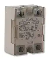


G3NA210BUTUAC200240OP
Solid State Relay, 10 A, 264 VAC, Panel Mount, Screw, Zero Crossing
- Manufacturer: OMRON INDUSTRIAL AUTOMATION
- Product type:
- Contact Configuration:-; Load Current:10A; Operating Voltage Max:264VAC; Relay Mounting:Panel; Relay Terminals:Screw; Switching Mode:Zero Crossing; Operating Voltage Min:19VAC; Control Voltage Min:200VAC; Contr
- Load Current: 10A
- Product Range: G3NA Series
- Relay Mounting: Panel Mount
- Switching Mode: Zero Crossing
- Relay Terminals: Screw
- Control Voltage Max: 240VAC
- Control Voltage Min: 200VAC
- Contact Configuration: -
- Operating Voltage Max: 264VAC
- Operating Voltage Min: 19VAC
| Delivery and price | |
|---|---|
| Units per pack | 1 |
| Price | 23.2 € |
| Current stock | 10+ |
| Lead time | 30 days |
**G3NA**

## ee **Solid-state Relay**

## **A Wide Range of Models with 5- to 40-A Output Currents and Up to 480-VAC/200-VDC Output Voltages**

All models feature the same compact dimensions to provide a uniform mounting pitch.

- Built-in varistor effectively absorb external surges.

- Operation indicator (red LED) enables monitoring operation.

Protective cover for greater safety.

- Standard models approved by UL/CSA and -UTU models by VDE (TÜV).

## ~~Ordering Information~~

|**Isolation**<br>~~a~~|**Zero cross**<br>**function**<br>~~es~~|**Indicator**|**Rated output load**<br>**(Applicable output load)**|**Rated input voltage**|**Model**|
|---|---|---|---|---|---|
|Phototriac<br>~~a~~<br>~~a~~|Yes<br>~~es~~|Yes<br>|**5**A**a**t 24 t**o**24**0**VA**C***<br>**(19 t**<br>**264 VAC)**<br>o<br>~~Se~~|5 to 24 VDC<br>~~Se~~|G3NA-205B<br>~~Se~~|
|**Photocou**p**ler**<br>~~a~~||||100 to 120 VAC<br>~~Se~~||
|||||200 to 240 VAC<br>~~Se~~||
|Phototriac|||1**0**A**a**t 24 t**o**24**0**VA**C***<br>**(19 t**<br>**264 VAC)**<br>o<br>~~ae~~|5 to 24 VDC<br>~~ae~~|G3NA-210B<br>~~ae~~|
|Ph**o**t**ocou**pl**e**r||||100 to 120 VAC<br>~~ae~~||
|||||200 to 240 VAC<br>~~ae~~||
||||1**0**A**a**t 2**00**t**o**4**80**VA**C***<br>**(180 t**<br>**528 VAC)**<br>o<br>~~ae~~<br>~~ee~~|5 to 24 VDC<br>~~ae~~<br>~~ee~~|G3NA-410B<br>~~ae~~<br>~~ee~~|
|||||100 to 240 VAC<br>~~ee~~||
||---<br>~~ee ~~||1**0**A**a**t**5**t**o**2**00**VD**C***<br>**(4 t**<br>**220 VDC)**<br>o<br>|5 to 24 VDC<br>|G3NA-D210B<br>|
|||||100 to 240 VAC<br>||
|Phototriac|Yes<br>||2**0**A**a**t 24 t**o**24**0**VA**C***<br>**(19 t**<br>**264 VAC)**<br>o<br> ~~Se~~|5 to 24 VDC<br>~~Se~~|G3NA-220B<br>~~Se~~|
|Ph**o**t**ocou**pl**e**r<br>~~oo~~<br>~~a~~||||100 to 120 VAC<br>~~Se~~||
|||||200 to 240 VAC<br>~~Se~~||
||||2**0**A**a**t 2**00**t**o**4**80**VA**C***<br>**(180 t**<br>**528 VAC)**<br>o<br>~~ee~~|5 to 24 VDC<br>~~ee~~|G3NA-420B<br>~~ee~~<br>~~ae~~|
|||||100 to 240 VAC<br>~~ee~~||
|Phototriac<br>~~oo~~<br>~~a~~|||4**0**A**a**t 24 t**o**24**0**VA**C***<br>**(19 t**<br>**264 VAC)**<br>o<br>~~ee~~<br>~~i~~|5 to 24 VDC<br>~~ee~~<br>~~i~~|G3NA-240B<br>~~ee~~<br>~~i~~<br>~~ae~~|
|Ph**o**t**ocou**pl**e**r<br>~~oo~~<br>~~a~~||||100 to 120 VAC<br>~~ee~~<br>~~i~~||
|||||200 to 240 VAC<br>~~ee~~<br>~~i~~||
||||4**0**A**a**t 2**00**t**o**4**80**VA**C***<br>**(180 t**<br>**528 VAC)**<br>o<br>~~ee~~<br>~~a~~|5 to 24 VDC<br>~~ee~~|G3NA-440B<br>~~ee~~<br>~~ae~~<br>~~ee~~|
|||||100 to 240 VAC<br>~~ee~~||
||||50 A at 200 to 480 VAC*<br>(180 to 528 VAC)<br>~~ee~~|5 to 24 VDC<br>~~ee~~<br>~~ee~~|G3NA-450B<br>~~ae~~<br>~~ee~~<br>~~ee~~|


*Loss time increases under 75 VAC. (Refer to page 148.) **Note:** When ordering a TÜV-approved model, add “-UTU” to the model number as shown below: Example: G3NA-210B-UTU

1

~~**G3NA**~~

~~**G3NA**~~

## **Accessories (Order Separately) Heat Sink**

The following heat sinks are thin and can be DIN-track mounted (except Y92B-P250). See Dimensions for details.

|**Model**|**Applicable SSR**|
|---|---|
|**Y92B-N50**|G3NA-205B, G3NA-210B, G3NA-D210B,<br>G3NA-410B, G3NE-205T(L), G3NE-210T(L)|
|**Y92B-N100**|G3NA-220B, G3NA-420B, G3NE-220T(L)|
|**Y92B-N150**|G3NA-240B, G3NA-440B|
|**Y92B-P250**|G3NA-450B|


## **Low-cost Models**

|**Model**|**Applicable SSR**|
|---|---|
|**Y92B-A100**|G3NA-205B, G3NA-210B, G3NA-D210B,<br>G3NA-220B, G3NA-410B, G3NA-420B|
|**Y92B-A150N**|G3NA-240B, G3NA-440B|
|**Y92B-A250**|G3NA-440B|


## **Mounting Bracket**

|**Y92B-A250**<br>G3NA-440B<br>**Mounting Bracket**<br>|**Y92B-A250**<br>G3NA-440B<br>**Mounting Bracket**<br>|
|---|---|
|Usedto mount the G3NA with a mounting dimension of 56 mm.||
|**Model**|**Applicable SSR**|
|**R99-11**|G3NA-240B,G3NA-440B|


See Dimensions for details. (Refer to page 148.)

## ~~Specifications~~

## **Ratings**

## **Input (Ambient Temperature: 25** ° **C)**

|**Model**|**Rated voltage**|**Operating voltage**|**Impedance**|**Voltage level**<br>**Must operate**<br>**voltage**<br>**Must release**<br>**voltage**|**Voltage level**<br>**Must operate**<br>**voltage**<br>**Must release**<br>**voltage**|**Voltage level**<br>**Must operate**<br>**voltage**<br>**Must release**<br>**voltage**|
|---|---|---|---|---|---|---|
|||||||**Must release**<br>**voltage**|
|**G3NA-2**��**B**|5 to 24 VDC|4 to 32 VDC|7 mA max.*|4 VDC max.||1 VDC min.|
||100 to 120 VAC|75 to 132 VAC|36 kΩ±20%|75 VAC max.**||20 VAC min.**|
||200 to 240 VAC|150 to 264 VAC|72 kΩ±20%|150 VAC max.**||40 VAC min.**|
|**G3NA-4**��**B**<br>**G3NA-D210B**|5 to 24 VDC|4 to 32 VDC|5 mA max.*|4 VDC max.||1 VDC min.|
||100 to 240 VAC|75 to 264 VAC|72 kΩ±20%|75 VAC max.||20 VAC min.|
|**Note:**<br>The input impedance is measured at the maximum value of the rated supply voltage (for example, with the model rated at 100 to<br>120 VAC,the input impedance is measured at 120 VAC).<br>*With constant current input circuit system. The impedance for the G3NA-���B-UTU is 15 mA max.<br>**Refer to theEngineering Datafor further details.<br>**Output**|||||||
|**Model**|||**Applicable load**||||
||**Rated load voltage**|**Load voltage range**|**Load current**||**Inrush current**||
||||**With heat sink***|**Without heat sink**|||
|**G3NA-205B**|24 to 240 VAC|19 to 264 VAC|0.1 to 5 A|0.1 to 3 A|60 A(60 Hz, 1 cycle)||
|**G3NA-210B**|||0.1 to 10 A|0.1 to 4 A|150 A (60 Hz, 1 cycle)||
|**G3NA-410B**|200 to 480 VAC|180 to 528 VAC|0.2 to 10 A|0.2 to 4 A|||
|**G3NA-220B**|24 to 240 VAC|19 to 264 VAC|0.1 to 20 A|0.1 to 4 A|220 A (60 Hz, 1 cycle)||
|**G3NA-420B**|200 to 480 VAC|180 to 528 VAC|0.2 to 20 A|0.2 to 4 A|||
|**G3NA-240B**|24 to 240 VAC|19 to 264 VAC|0.1 to 40 A|0.1 to 6 A|440 A (60 Hz, 1 cycle)||
|**G3NA-440B**|200 to 480 VAC|180 to 528 VAC|0.2 to 40 A|0.2 to 6 A|||
|**G3NA-450B**|200 to 480 VAC|180 to 528 VAC|0.2 to 50 A|0.2 to 6 A|||
|**G3NA-D210B**|5 to 200 VDC|4 to 220 VDC|0.1 to 10 A|0.1 to 4 A|20 A(10 ms)||


*When OMRON’s heat sink (refer to the accessories) or a heat sink of specified size is used.

2

~~**G3NA**~~

~~**G3NA**~~

## **Characteristics**

|**Characteristics**|||||
|---|---|---|---|---|
|**Item**|**G3NA-205B, -210B,**<br>**-220B**|**G3NA-240B**|**G3NA-410B, -420B,**<br>**-440B, -450B**|**G3NA-D210B**|
|**Operate time**|1/2 of load power source cycle + 1 ms max. (DC input)<br>3/2 of load power source cycle + 1 ms max. (AC input)|||1 ms max. (DC input)<br>30 ms max. (AC input)|
|**Release time**|1/2 of load power source cycle + 1 ms max. (DC input)<br>3/2 of load power source cycle + 1 ms max. (AC input)|||5 ms max. (DC input)<br>30 ms max. (AC input)|
|**Output ON voltage drop**|1.6 V(RMS)max.||1.8 V(RMS)max.|1.5 V max.|
|**Leakage current**|5 mA max. (at 100 VAC)<br>10 mA max. (at 200 VAC)||10 mA max. (at 200 VAC)<br>20 mA max. (at 400 VAC)|5 mA max. (at 200 VDC)|
|**Insulation resistance**|100 MΩmin.(at 500 VDC)||||
|**Dielectric strength**|2,500 VAC, 50/60 Hz for 1 min||||
|**Vibration resistance**|Malfunction: 10 to 55 Hz, 1.5-mm double amplitude||||
|**Shock resistance**|Malfunction: 1,000 m/s2||||
|**Ambient temperature**|Operating: –30°C to 80°C (with no icing or condensation)<br>Storage:<br>–30°C to 100°C (with no icing or condensation)||||
|**Approved standards**|UL508 File No.E64562/CSA C22.2 (No.0, No.14) File No.LR35535<br>TÜV R9151660 (EN60950)||||
|**Ambient humidity**|Operating: 45% to 85%||||
|**Weight**|Approx. 60g|Approx. 70g|Approx. 80g|Approx. 70g|


3

~~**G3NA**~~

~~**G3NA**~~

## ~~Engineering Data~~

## **Load Current vs. Ambient Temperature Characteristics**

**G3NA-205B G3NA-210B/410B**

## **G3NA-220B/420B**

**==> picture [484 x 506] intentionally omitted <==**

**----- Start of picture text -----**<br>
20<br>16<br>Io T<br>With standard heat sink 10<br>iSaaa| (Y92B-A100 or Y92B-N50) or aluminum platemeasuring 75 mm x 75mm x 13.2 mm (W x H x D) ausen 8 With standard heat sink(Y92B-A100 or Y92B-N50)or aluminum plate measuring 150 mm x 150 mm x13.2 mm (W x H x D) FEET - XoIN TT) 15IEEE With standard heatsink (Y92B-A100 orY92B-N100) or alumi-num plate measuring200 mm x 200 mm x13.2 mm (W x H x D) TAS<br>Without heat sink 6<br>5 With iron plate measuring100 x 100 x 0.8 (W x H x D) ST With iron plate measuring100 x 100 x 0.8 (W x H x D) LO<br>4<br>Without heat sink<br>topoN 2 Nie Without heat sink \|<br>oPee 0 Oe)S\N) EERR AS|<br>30—20 it} 20 40 60 80 100 —30—20 i} 20 40 60 80 100 o 30-20 0 20 40 60. 80 100<br>Ambient temperature (°C) Ambient temperature (°C) Ambient temperature (°C)<br>G3NA-240B G3NA-440B G3NA-D210B<br>50 20<br>With Y92B-<br>45 A250 or heat<br>sink with a ra-<br>L With |  standard heat 40 ian diation efcy of 1°C/W.ficien- 10 With standard heat sink<br>sink (Y92B-A150N (Y92B-A100 or Y92B-N50)<br>or Y92B-N150) 30 With standard heatsink (Y92B-A150N or or aluminum plate measuring 150 mm x 150 mm x -<br>Y92B-N150) 13.2 mm (W x H x D)<br>6<br>TELL 20 wn 5 With iron plate measuring100 x 100 x 0.8 (W x H x D) \<br>With iron plate measuring With iron plate measuring 4 Without heat sink<br>100 x 100 x 0.8 (W x H x D) 12 100 x 100 x 0.8 (W x H x D)<br>10<br>: Without heat sink 6 Without heat sink 2 HEN<br>4<br>2<br>—30—20 ASS 0 20 40 = N)60 80 00 0 —30—20: FS 0 20 40 S 60 80 100 0 —30—20 S is} 20san40 66 780<br>Ambient temperature (°C) Ambient temperature (°C) Ambient temperature (°C)<br>G3NA-450B<br>TEtt<br>With standard heat sink<br>(Y92B-P250)<br>Tyo i<br>HHA30 Na<br>\ |<br>"0aeee Without heat sink eee a<br>—36—20 0 20 40 60 80 400<br>Ambient temperature (°C)<br>Load current (A) Load current (A) Load current (A)<br>Load current (A) Load current (A) Load current (A)<br>Load current (A)<br>**----- End of picture text -----**<br>


4

~~**G3NA**~~

~~**G3NA**~~

## **Inrush Current Resistivity**

Non-repetitive (Keep the inrush current to half the rated value if it occurs repetitively.)

**==> picture [485 x 397] intentionally omitted <==**

**----- Start of picture text -----**<br>
G3NA-205B G3NA-210B/410B G3NA-220B/420B<br>Ao ~.AD soon<br>NUE “ON<br>NE ET) PINT LEN<br>PUNE E&P NX<br>P UNE y<br>PUNE NG c ——<br>CoS UTE SAE)<br>CePA oN<br>aT 30 50 100 200 500 1,000 5,000 tUULU°G 30 50 100 200 500 PS)1,000 5,000 toeary 30 50 100 200 500 1.000 §,000<br>Energizing time (ms) Energizing time (ms) Energizing time (ms)<br>Temperature Characteristics<br>(with Must Operate Voltage<br>and Must Release Voltage)<br>G3NA-240B/440B/450B G3NA-D210B G3NA-2 OO B AC Input<br>30* ttt} TlIi]1] wf. [~~.]<br>400 a 7. _<br>\ A9<br>a NJ<br>wot LN eos Ler<br>N 9s NN<br>coo \ aMSE ~NS<br>~e Pe NN<br>| a —<br>hh| a a<br>“COTTE; REa a<br>10 30 50 100 200 500 1,000 5,000 10 =20 30 ©5070 100 200 300500 1,000 2,000 —30 —20 0 20 40 60 80<br>Energizing time (ms) Energizing time (ms) Ambient temperature (°C)<br>Inrush current (A. Peak) Inrush current (A. Peak) Inrush current (A. Peak)<br>ariation rate (%)<br>V<br>Inrush current (A. Peak) Inrush current (A. Peak)<br>**----- End of picture text -----**<br>


## **Heat Sink Size vs. Load Current**

## **G3NA-220B**

**==> picture [156 x 143] intentionally omitted <==**

**----- Start of picture text -----**<br>
Ambient temperature80°C Ambient temperature40°C<br>1,000 = So<br>700 Ff<br>eS a<br>500 ye KR<br>_100 +fFia A47<br>70 ==><br>x050 aaya a  aan ae ne<br>— re<br>Aluminum plate<br>3.2 mm thick<br>0 2 4 6 8 10 12 14 16 18 20 22 24<br>Load current (A)<br>2<br>Heat sink size (cm   )<br>**----- End of picture text -----**<br>


**Note:** The heat sink size refers to the combined area of the sides of the heat sink that radiate heat. For example, when a current of 18 A is allowed to flow through the SSR at 40°C, the graph shows that the heat sink size is about 450 cm[2] . Therefore, if the heat sink is square, one side of the heat sink must be 15 cm (15[2] x 2 = 450) or longer.

5

~~**G3NA**~~

~~**G3NA**~~

## ~~Dimensions~~

**Note:** All units are in millimeters unless otherwise indicated.

In the case of surface mounting, a 30% derating of the load current is required.

The orientation indicated by the external dimensions is not the correct mounting orientation. When opening mounting holes, refer to the mounting hole dimensions.

## **G3NA-205B, G3NA-210B, G3NA-220B, G3NA-410B, G3NA-420B**

**==> picture [482 x 422] intentionally omitted <==**

**----- Start of picture text -----**<br>
Four, M4 x 8<br>4.5 dia. screws Mounting Holes Terminal Arrangement/<br>Internal Connections<br>(Top View)<br>Two, 4.3-dia. Load<br>or M4 holes Load<br>power<br>58 max. 47.5 44 supply<br><x eV Q Load<br>ne rf fee 1 2<br>47.6±0.2<br>(-) (+)<br>Operating 13.8 4 3<br>. 4.525 indicator 25 max. | Input<br>a 43 max. 27 max. eee<br>G3NA-240B, G3NA-440B, G3NA-450B<br>4.5 dia. Two, M5 x 12 screws Mounting Holes Terminal Arrangement/<br>Internal Connections<br>(Top View)<br>Two, 4.3-dia. Load<br>ZOCOR, ANS ) or M4 holes Load<br>58 min.47.5 44 power<br>Load supply<br>[SAPgy2 ~~ ‘ PR Q Fl| ce 1 2<br>47.6±0.2<br>Operating<br>indicator (-) (+)<br>Ai S =e 13.8 4 3<br>4.525 Two, 25 max. Input<br>43 max. - M 4 x 8 27 max. : "|<br>G3NA-D210B Four,<br>M4 x 8<br>4.5 dia. screws<br>Mounting Holes Terminal Arrangement/<br>Internal Connections<br>(Top View)<br>Two, 4.3-dia. Load<br>or M4 holes<br>58 max. 47.5 44 Load<br>power<br>Load supply<br>1 2<br>47.6±0.2 - +<br>, ae Operating 13.8 |<br>_ 4.525 indicator 25 max. (-)44 (+)33<br>43 max. 27 max. Input<br>aaa Lp oe<br>**----- End of picture text -----**<br>


Load Load power Load supply 1 2 - + (-)44 (+)33 Input ~~oe~~

**==> picture [477 x 125] intentionally omitted <==**

**----- Start of picture text -----**<br>
Heat Sink Mounting Holes<br>Y92B-N50<br>4.6 dia. Two, M3 holesTwo, M4 holes Two, 3.2-dia. 35 ±0.2<br>holes<br>35 30.5±0.3 44 max. 30 47 max. Two, 4.4-dia.<br>or M4 holes<br>90±0.4<br>47.6 5.6 5 6 4.5<br>ng —e 77 max. Et<br>90±0.3 51 max.<br>100 max.<br>Weight: approx. 200 g<br>**----- End of picture text -----**<br>


6

~~**G3NA**~~

~~**G3NA**~~

**==> picture [486 x 651] intentionally omitted <==**

**----- Start of picture text -----**<br>
Y92B-N100 Mounting Holes<br>Two, M3 holes Two, M4 Two, 3.2-dia. holes<br>4.6 dia. holes<br>35 ±0.2<br>71 max.<br>35 30.5±0.3 30 75 max.<br>Two, 4.4-dia.<br>or M4 holes<br>90±0.4<br>47.6 5.6 28 5 13 4.5<br>77 max. 100 max.<br>90±0.3<br>100 max.<br>Weight: approx. 400 g<br>Y92B-N150 47.6 Three, Two, 3.2-dia. holes Mounting Holes<br>M4 35 ±0.2<br>4.6 dia. holes<br>35 100 max. 30 104 max. Two, 4.4-dia.or M4 holes<br>90±0.4<br>56±0.3 5.6 28 5 13 4.5<br>77 max. 100 max.<br>90±0.3 Weight: approx. 560 g<br>100 max.<br>Y92B-A100 Y92B-A150N Y92B-A250<br>Three, M4 holes<br>Three, M4 holes<br>Two, M4 holes 100.5 max.<br>1.5 80.5 max.<br>R2.2 47.6 R2.2 47.6<br>9.6<br>2<br>47.6 50±0.1 50±0.1 1.5<br>56±0.5 56±0.5 30<br>50±0.1<br>100 max. 150 max. { se 250 max. a 45.5 max.<br>Mounting Holes +f<br>Y92B-A100 Mounting Holes<br>Y92B-A150 ll ll Four, 4.5 dia. or M4<br>Y92B-A250<br>Four, M4<br>Four, 4.3-dia. or M4 holes<br>190.5 max.<br>d al TT<br>90±0.1<br>ny 50±0 .1 ok |<br>Four, R2.5<br>130.5 max.<br>70 max.<br>± ±<br>± 90  0.1 90  0.1<br>90  0.1<br>**----- End of picture text -----**<br>


7

~~**G3NA**~~

~~**G3NA**~~

**==> picture [27 x 7] intentionally omitted <==**

**----- Start of picture text -----**<br>
R99-11<br>**----- End of picture text -----**<br>


**==> picture [198 x 72] intentionally omitted <==**

**----- Start of picture text -----**<br>
16<br>8<br>fo<br>5<br>12.5<br>21 56<br>I<br>STR 4 T 4.6 lis»<br>**----- End of picture text -----**<br>


Use Mounting Bracket R99-11 so that the

G3NA-240B can be mounted with the same pitch as that of the G3N-240B.

## ~~Precautions~~

Refer to pages 11 to 19 for general precautions.

## **Load Connection**

For an AC load, use a power supply rated at 50 or 60 Hz. The maximum operating frequency is 10 Hz.

The G3NA has a built-in varistor for overvoltage protection.

## **Zero Cross Function**

An SSR with a zero cross function operates when an AC load voltage reaches the zero point or its vicinity. This reduces clicking noises when the load is input, and minimizes the influence of an inductive load, such as a lamp, heater, or motor, on the power supply because the inrush current of the load is reduced. This can also minimize the scale of the inrush current protection circuit.

When attaching a heat sink to the G3NA, apply Silicone Grease or equivalent heat conductive grease on the heat sink. (Toshiba Silicon, Shinetsu Silicon, etc.)

Tighten the mounting screws of the heat sink with a torque of 0.78 to 0.98 N m.

**EN55011 Measurement of Mains Terminal Disturbance Voltage**

The G3NA-UTU conforms to EN55011 standards when a capacitor - is connected to the load power supply as shown in the following cir cuit diagram.

**==> picture [101 x 22] intentionally omitted <==**

**----- Start of picture text -----**<br>
Load<br>Input G3NA-UTU Output<br>**----- End of picture text -----**<br>


**==> picture [60 x 52] intentionally omitted <==**

**----- Start of picture text -----**<br>
Output (load voltage)<br>Input [ON] OFF<br>**----- End of picture text -----**<br>


At a low applied voltage, such as 24 VAC, the load current is not fully supplied. When the Unit is switched ON, the voltage required to power the Unit deprives the output signal of the necessary voltage level and thus creates loss time. The lower the load voltage is, the greater the loss time is. This condition, however, will not create any serious problems.

Recommended Capacitor:

Nissei Denki’s MKT-series R40 (1 µF)

The output terminal side of the G3NA-D210B is connected to a builtin diode for protecting the SSR from damage that may result from reverse connection. The SSR, however, cannot withstand one minute or more if the wires are connected in reverse order. Therefore, pay the utmost attention not to make polarity mistakes on the load side.

**==> picture [27 x 6] intentionally omitted <==**

**----- Start of picture text -----**<br>
Loss time<br>**----- End of picture text -----**<br>


For a DC or L load, a diode should be connected in parallel the load to absorb the counter electromotive force of the load.

**==> picture [192 x 41] intentionally omitted <==**

**----- Start of picture text -----**<br>
Load<br>o—f{o Input SSR O }—o [| 1 Load power<br>fe) O O O i supply<br>**----- End of picture text -----**<br>


## **ALL DIMENSIONS SHOWN ARE IN MILLIMETERS.**

To convert millimeters into inches, multiply by 0.03937. To convert grams into ounces, multiply by 0.03527.

Cat. No. K067-E1-1C

8
Updated at June 10, 2026
With a legacy spanning over 80 years, Omron Industrial Automation is a globally recognized leader in the manufacture of advanced industrial control and automation components. Renowned for their reliability and engineering excellence, Omron delivers comprehensive solutions that enhance efficiency, machine safety, and precision across a wide range of manufacturing environments. Our extensive portfolio of Omron products is heavily focused on their industry-leading sensing and switching technologies. We offer a vast selection of sensors, excelling specifically in high-performance proximity sensors, light sensors, and temperature sensors. Complementing this range are robust switching solutions, featuring a deep inventory of power relays, solid-state relays, safety relays, and essential relay accessories designed for demanding operational requirements. Beyond sensing and switching, Omron is highly regarded for its precision automation and process control equipment. Our selection features highly accurate temperature controllers, versatile process controllers, and sophisticated panel displays and instrumentation. To support these fundamental systems, we also supply dependable Omron power supplies, notably AC/DC converters, alongside vital connectivity components like DIN rail terminal blocks to ensure secure, efficient, and complete industrial setups.
About Novapart
Novapart is a B2B electronic component broker specialising in stock shortages and cost reduction. We source hard-to-find parts and identify compliant alternatives across a catalogue of 410,000+ components from 500+ manufacturers.
Learn more →Stock Shortage Specialist
When a component is unavailable, discontinued or has an unacceptable lead time, we tap into our network of vetted European and Asian distributors to source what you need — without compromising on quality or traceability.
Request a quote →Compliant Alternatives
We identify pin-to-pin, electrically equivalent substitutes that meet the same certifications (RoHS, AEC-Q100, REACH) as your original specification — validated against datasheets, not just part numbers. Often at a lower cost.
BOM Analysis service →