
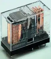


G2R-1A-TAC-120-
RELAY, SPST-NO, 250VAC, 30VDC, 10A
- Manufacturer: OMRON INDUSTRIAL AUTOMATION
- Product type: Power Relays
- Coil Type: Non Latching
- Coil Voltage: 120VAC
- Product Range: G2R Series
- Relay Mounting: Panel Mount
- Coil Resistance: 6.5kohm
- Contact Current: 10A
- Relay Terminals: Quick Connect
- Contact Material: Silver Alloy
- Contact Voltage VAC: 250VAC
- Contact Voltage VDC: 30VDC
- Contact Configuration: SPST-NO
| Delivery and price | |
|---|---|
| Units per pack | 50 |
| Price | 8.82 € |
| Current stock | 10+ |
| Lead time | 30 days |
G2R PCB Power Relay

G 2 R

## **The Best Seller G2R**

- 1General purpose power Relays of single-pole10 A and double-pole 5 A.

- Safety-oriented design with dielectric strength of 5,000 V between coil and contacts, and surge resistance of 10,000 V.

- AC and DC types are both available for operational coils.

## **RoHS Compliant**

## ■ **Model Number Legend**

## G2R- @ - @@@@ - @@

— — — — — — — 1 2 3 4 5 6 7

## **4. Contact Type**

## **1. Relay Function**

None: Single Z : Bifurcated contact

None: Single-side stable K : Double-winding latching

## **2. Number of poles**

## **5. Enclosure rating**

1: 1-pole None: Flux protection 2: 2-pole (T-type is an enclosed relay)

## **3. Contact Form**

4 : Fully sealed

None: NO/NC

## **6. Terminal Shape**

None: PCB terminals

T : Quick-connect (upper bracket mounting #187)

## **7. Classification**

None: Standard E : High-capacity H : High-sensitivity U : For ultrasonically cleanable

Z : Full-wave rectifier

A : NO

## ■ **Model Configuration**

|Classification<br>Number of poles<br>Terminal<br>Shape<br>Enclosure<br>rating<br>Contact<br>form|Classification<br>Number of poles<br>Terminal<br>Shape<br>Enclosure<br>rating<br>Contact<br>form|Classification<br>Number of poles<br>Terminal<br>Shape<br>Enclosure<br>rating<br>Contact<br>form|Classification<br>Number of poles<br>Terminal<br>Shape<br>Enclosure<br>rating<br>Contact<br>form|1-pole|1-pole|2-pole|2-pole|Minimum<br>packing<br>unit|
|---|---|---|---|---|---|---|---|---|
|||||SPST-NO (1a)|SPDT (1c)|DPST-NO (2a)|DPDT (2c)||
|PCB terminals|Standard|Flux protection|AC|G2R-1A|G2R-1|G2R-2A|G2R-2|100<br>pcs/tray|
||||DC||||||
|||Fully sealed|AC|G2R-1A4|G2R-14|G2R-2A4|G2R-24||
||||DC||||||
||Bifurcated<br>contact|Flux protection|DC|G2R-1AZ|G2R-1Z|−|−|50<br>pcs/tray|
|||Fully sealed||G2R-1AZ4|G2R-1Z4|−|−||
||High-capacity|Flux protection|AC|G2R-1A-E|G2R-1-E|−|−|100<br>pcs/tray|
||||DC||||||
||High-sensitivity|Flux protection|DC|G2R-1A-H|G2R-1-H|G2R-2A-H|G2R-2-H||
||Double-winding<br>latching|Flux protection|DC|G2RK-1A|G2RK-1|G2RK-2A|G2RK-2|50<br>pcs/tray|
|Quick-connect|Standard|Unsealed|AC|G2R-1A-T|G2R-1-T|−|−|100<br>pcs/tray|
||||DC||||||


Note 1. Full-wave rectifier and supersonic cleaner compatible models are also available. Refer to page 3. 2.Sockets for PCB terminal models are not provided.

**1**

G2R

**PCB Power Relay**

G 2 R

## ■ **Ordering Information**

## ● **PCB Terminal Models**

|||Number of poles|1-pole|1-pole|2-pole|2-pole|
|---|---|---|---|---|---|---|
|Classification|Enclosure rating|Contact form|Model|Rated coil voltage|Model|Rated coil voltage|
|Standard|Flux protection|NO|**G2R-1A**|12, 24, 100/(110) VAC|**G2R-2A**|12, 24, 100/(110) VAC|
|||||200/(220) VAC||200/(220) VAC|
|||||5, 6, 12, 24, 48 VDC||5, 6, 12, 24, 48 VDC|
|||||100 VDC||100 VDC|
|||NO/NC|**G2R-1**|12, 24, 100/(110) VAC|**G2R-2**|12, 24, 100/(110) VAC|
|||||200/(220) VAC||200/(220) VAC|
|||||5, 6, 12, 24, 48 VDC||5, 6, 12, 24, 48 VDC|
|||||100 VDC||100 VDC|
||Fully sealed|NO|**G2R-1A4**|12, 24, 100/(110) VAC|**G2R-2A4**|12, 24, 100/(110) VAC|
|||||200/(220) VAC||200/(220) VAC|
|||||5, 6, 12, 24, 48 VDC||5, 6, 12, 24, 48 VDC|
|||||100 VDC||100 VDC|
|||NO/NC|**G2R-14**|12, 24, 100/(110) VAC|**G2R-24**|12, 24, 100/(110) VAC|
|||||200/(220) VAC||200/(220) VAC|
|||||5, 6, 12, 24, 48 VDC||5, 6, 12, 24, 48 VDC|
|||||100 VDC||100 VDC|
|High-sensitivity|Flux protection|NO|**G2R-1A-H**|5, 6, 12, 24, 48 VDC|**G2R-2A-H**|5, 6, 12, 24, 48 VDC|
|||NO/NC|**G2R-1-H**|5, 6, 12, 24, 48 VDC|**G2R-2-H**|5, 6, 12, 24, 48 VDC|
|Double-winding<br>latching||NO|**G2RK-1A**|5, 6, 12, 24 VDC|**G2RK-2A**|5, 12, 24 VDC|
|||NO/NC|**G2RK-1**|5, 6, 12, 24 VDC|**G2RK-2**|5, 6, 12, 24 VDC|
|Bifurcated<br>contact|Flux protection|NO|**G2R-1AZ**|12, 24, 48 VDC||−|
|||||100 VDC|||
|||NO/NC|**G2R-1Z**|5, 6, 12, 24, 48 VDC|||
|||||100 VDC|||
||Fully sealed|NO|**G2R-1AZ4**|5, 12, 24, 48 VDC||−|
|||||100 VDC|||
|||NO/NC|**G2R-1Z4**|5, 12, 24, 48 VDC|||
|||||100 VDC|||
|High-capacity|Flux protection|NO|**G2R-1A-E**|12, 24, 100/(110) VAC||−|
|||||200/(220) VAC|||
|||||5, 6, 12, 24, 48 VDC|||
|||||100 VDC|||
|||NO/NC|**G2R-1-E**|12, 24, 100/(110) VAC||−|
|||||200/(220) VAC|||
|||||5, 6, 12, 24, 48 VDC|||
|||||100 VDC|||


Note: When ordering, add the rated coil voltage to the model number. Example: G2R-1A AC12 Rated coil voltage

However, the notation of the coil voltage on the product case as well as on the packing will be marked as @@ VAC.

**2**

G2R

**PCB Power Relay**

G 2 R

## ● **Quick-connect Terminal (#187)**

|||Number of poles|1-pole|1-pole|
|---|---|---|---|---|
|Classification<br>Enclosure rating||Contact form|Model|Rated coil voltage|
|Standard|Unsealed|NO|**G2R-1A-T**|12, 24, 100/(110) VAC|
|||||200/(220) VAC|
|||||5, 6, 12, 24, 48 VDC|
|||||100 VDC|
|||NO/NC|**G2R-1-T**|12, 24, 100/(110) VAC|
|||||200/(220) VAC|
|||||5, 6, 12, 24, 48 VDC|
|||||100 VDC|


## ● **Full-wave Rectifier**

|||Number of poles|1-pole|1-pole|2-pole|2-pole|
|---|---|---|---|---|---|---|
|Classification|Enclosure rating|Contact form|Model|Rated coil voltage|Model|Rated coil voltage|
|Standard|Flux protection|NO|**G2R-1A-Z**|5, 12, 24 VDC|**G2R-2A-Z**|5, 6, 12, 24, 48 VDC|
|||||100 VDC||100 VDC|
|||NO/NC|**G2R-1-Z**|5, 12, 24, 48 VDC|**G2R-2-Z**|12, 24, 48 VDC|
|||||100 VDC||100 VDC|
||Fully sealed|NO|**G2R-1A4-Z**|5, 12, 48 VDC|**G2R-2A4-Z**|24, 48 VDC|
|||||100 VDC||100 VDC|
|||NO/NC|**G2R-14-Z**|5, 12, 24, 48 VDC|**G2R-24-Z**|5, 12, 24 VDC|
|||||100 VDC||100 VDC|
|High-capacity|Flux protection|NO|**G2R-1A-EZ**|5, 12, 24 VDC||−|
|||||100 VDC|||
|||NO/NC|**G2R-1-EZ**|12, 24, 48 VDC|||


## ● **For Ultrasonically Cleanable**

|||Number of poles|1-pole|1-pole|2-pole|2-pole|
|---|---|---|---|---|---|---|
|Classification<br>Enclosure rating||Contact form|Model|Rated coil voltage|Model|Rated coil voltage|
|Standard|Fully sealed|NO|**G2R-1A4-U**|12, 24, 100/(110) VAC|**G2R-2A4-U**|100/(110) VAC|
|||||200/(220) VAC||−|
|||||5, 6, 12, 24, 48 VDC||5, 12, 24 VDC|
|||NO/NC|**G2R-14-U**|100/(110) VAC<br>200/(220) VAC|**G2R-24-U**|24, 100/(110) VAC<br>200/(220) VAC|
|||||5, 12, 24, 48 VDC||5, 12, 24, 48 VDC|
|||||100 VDC||100 VDC|


Note: When ordering, add the rated coil voltage to the model number. Example: G2R-1A-T AC12

Rated coil voltage However, the notation of the coil voltage on the product case as well as on the packing will be marked as @@ VAC.

**3**

G2R

**PCB Power Relay**

G 2 R

## ■ **Ratings**

## ● **Coil**

|Classification|Item|Rated current (mA)|Rated current (mA)|Coil resistance<br>(Ω)|Must operate<br>voltage (V)|Must release<br>voltage (V)|Max. voltage<br>(V)|Power<br>consumption<br>(VA, W)|
|---|---|---|---|---|---|---|---|---|
||Rated voltage|50 Hz|60 Hz||% of rated voltage||||
|• Standard<br>• Quick-connect<br>• Fully sealed<br>• High-capacity|12 VAC|93|75|65|80% max.|30% min.|140%<br>(at 23°C)|Approx. 0.9<br>(60 Hz)|
||24 VAC|46.5|37.5|260|||||
||100/(110) VAC|11|9/(10.6)|4,600|||||
||200/(220) VAC|5.5|4.5/(5.3)|20,200|||||
|• Standard<br>• High-capacity<br>• Bifurcated contact<br>• Quick-connect<br>• Fully sealed|5 VDC|106||47|70% max.|15% min.|170%<br>(at 23°C)|Approx. 0.53|
||6 VDC|88.2||68|||||
||12 VDC|43.6||275|||||
||24 VDC|21.8||1,100|||||
||48 VDC|11.5||4,170|||||
||100 VDC|5.3||18,870|||||
|• High-sensitivity|5 VDC|71.4||70|70% max.|15% min.|170%<br>(at 23°C)|Approx. 0.36|
||6 VDC|60||100|||||
||12 VDC|30||400|||||
||24 VDC|15||1,600|||||
||48 VDC|7.5||6,400|||||


- Note 1. The rated current and coil resistance are measured at a coil temperature of 23°C with a tolerance of+15%/-20% (AC rated current) or ±10% (DC coil resistance). 2.AC coil resistances shown above are only reference values.

   - 3.The operating characteristics are measured at a coil temperature of 23°C.

   - 4.The “Max. voltage” is the maximum voltage that can be applied to the relay coil.

## ● **Coil: Double-winding Latching Relays**

|Item|Set Coil|Set Coil|Reset coil|Reset coil|Must set<br>voltage (V)|Must reset<br>voltage (V)|Max. voltage<br>(V)|Power consumption|Power consumption|
|---|---|---|---|---|---|---|---|---|---|
|Rated voltage|Rated current<br>(mA)|Coil resistance<br>(Ω)|Rated current<br>(mA)|Coil resistance<br>(Ω)|% of rated voltage|||Set Coil<br>(mW)|Reset coil<br>(mW)|
|5 VDC|167|30|119|42|70% max.|70% max.|140%<br>(at 23°C)|Approx.<br>850|Approx.<br>600|
|6 VDC|138|43.5|100|60||||||
|12 VDC|70.6|170|50|240||||||
|24 VDC|34.6|694|25|960||||||


- Note 1. The rated current and coil resistance are measured at a coil temperature of 23°C with a tolerance of ±10%.

   - 2.The operating characteristics are measured at a coil temperature of 23°C.

   - 3.The “Max. voltage” is the maximum voltage that can be applied to the relay coil.

**4**

G2R

**PCB Power Relay**

G 2 R

## ● **Contacts: Fully Protection Type**

|Classification|Standard  type<br>Quick-connect Terminal (1single-pole type)|Standard  type<br>Quick-connect Terminal (1single-pole type)|Standard  type<br>Quick-connect Terminal (1single-pole type)|Standard  type<br>Quick-connect Terminal (1single-pole type)|High-capacity type|High-capacity type|Bifurcated contact type|Bifurcated contact type|High-sensitivity type|High-sensitivity type|High-sensitivity type|High-sensitivity type|
|---|---|---|---|---|---|---|---|---|---|---|---|---|
|Number of poles|1-pole||2-pole||1-pole||2-pole||1-pole||2-pole||
|Item<br>Load|Resistive<br>load|Inductive<br>load<br>(cosφ= 0.4;<br>L/R = 7 ms)|<br>Resistive<br>load|Inductive<br>load<br>(cosφ= 0.4;<br>L/R = 7 ms)|<br>Resistive<br>load|Inductive<br>load<br>(cosφ= 0.4;<br>L/R = 7 ms)|<br>Resistive<br>load|Inductive<br>load<br>(cosφ= 0.4;<br>L/R = 7 ms)|Resistive<br>load|Inductive<br>load<br>(cosφ= 0.4;<br>L/R = 7 ms)|<br>Resistive<br>load|Inductive<br>load<br>(cosφ= 0.4;<br>L/R = 7 ms)|
|Contact type|Single||||Single||Bifurcated||Single||||
|Contact material|Ag-alloy (Cd free)||||||||||||
|Rated load|10 A at<br>250 VAC<br>10 A at 30<br>VDC|7.5 A at<br>250 VAC<br>5 A at 30<br>VDC|5 A at 250<br>VAC<br>5 A at 30<br>VDC|2 A at 250<br>VAC<br>3 A at 30<br>VDC|16 A at<br>250 VAC<br>16 A at 30<br>VDC|8 A at 250<br>VAC<br>8 A at 30<br>VDC|5 A at 250<br>VAC<br>5 A at 30<br>VDC|2 A at 250<br>VAC<br>3 A at 30<br>VDC|5 A at 250<br>VAC<br>5 A at 30<br>VDC|2 A at 250<br>VAC<br>3 A at 30<br>VDC|3 A at 250<br>VAC<br>3 A at 30<br>VDC|1 A at 250<br>VAC<br>1.5 A at<br>30 VDC|
|Rated carry current|10 A||5 A||16 A||5 A||5 A||3 A||
|Max. switching voltage|380 VAC, 125 VDC||||380 VAC, 125 VDC||||380 VAC, 125 VDC||||
|Max. switchingcurrent|10 A||5 A||16 A||5 A||5 A||3 A||
|Failure rate (P level)<br>(reference value) *|100 mA at 5 VDC||10 mA at 5 VDC||100 mA at 5 VDC||1 mA at 5 VDC||100 mA at 5 VDC||10 mA at 5 VDC||


* This value was measured at a switching frequency of 120 operations/min.

## ● **Contacts: Flux Sealed Type**

|Classification|Standard  type (Single contact type)|Standard  type (Single contact type)|Standard  type (Single contact type)|Standard  type (Single contact type)|Bifurcated contact type|Bifurcated contact type|
|---|---|---|---|---|---|---|
|Number of poles|1-pole||2-pole||1-pole||
|Item<br>Load|Resistive load<br>(cosφ= 1)|Inductive load<br>(cosφ= 0.4; L/R = 7 ms)|Resistive load<br>(cosφ= 1)|Inductive load<br>(cosφ= 0.4; L/R = 7 ms)|Resistive load<br>(cosφ= 1)|Inductive load<br>(cosφ= 0.4; L/R = 7 ms)|
|Contact type|Single||Single||Bifurcated||
|Contact material|Ag-alloy (Cd free)||||||
|Rated load|8 A at 250 VAC<br>8 A at 30 VDC|6 A at 250 VAC<br>4 A at 30 VDC|4 A at 250 VAC<br>4 A at 30 VDC|1.5 A at 250 VAC<br>2.5 A at 30 VDC|5 A at 250 VAC<br>5 A at 30 VDC|2 A at 250 VAC<br>3 A at 30 VDC|
|Rated carry current|8 A||4 A||5 A||
|Max. switching voltage|380 VAC, 125 VDC||380 VAC, 125 VDC||380 VAC, 125 VDC||
|Max. switchingcurrent|8 A||4 A||5 A||
|Failure rate (P level)<br>(reference value) *|100 mA at 5 VDC||10 mA at 5 VDC||1 mA at 5 VDC||


* This value was measured at a switching frequency of 120 operations/min.

## ● **Contacts: Latching Type**

|Number of poles|1-pole|1-pole|2-pole|2-pole|
|---|---|---|---|---|
|Item<br>Load|Resistive load<br>(cosφ= 1)|Inductive load<br>(cosφ= 0.4; L/R = 7 ms)|Resistive load<br>(cosφ= 1)|Inductive load<br>(cosφ= 0.4; L/R = 7 ms)|
|Contact type|Single||Single||
|Contact material|Ag-alloy (Cd free)||||
|Rated load|5 A at 250 VAC<br>5 A at 30 VDC|3.5 A at 250 VAC<br>2.5 A at 30 VDC|3 A at 250 VAC<br>3 A at 30 VDC|1.5 A at 250 VAC<br>2 A at 30 VDC|
|Rated carry current|5 A||3 A||
|Max. switching voltage|380 VAC, 125 VDC||380 VAC, 125 VDC||
|Max. switchingcurrent|5 A||3 A||
|Failure rate (P level)<br>(reference value) *|100 mA at 5 VDC||10 mA at 5 VDC||


* This value was measured at a switching frequency of 120 operations/min.

**5**

G2R

**PCB Power Relay**

G 2 R

## ■ **Characteristics**

## ● **Standard Relays**

|Item<br>Number ofpoles|Item<br>Number ofpoles|1-pole|2-pole|
|---|---|---|---|
|Contact resistance *1||30 mΩmax.|50 mΩmax.|
|Operate time *2||15 ms max.||
|Release time *2||AC: 10 ms max.; DC: 5 ms max.||
|Max.<br>operating<br>frequency|Mechanical|18,000 operations/hr||
||Electrical|1,800 operations/hr||
|Insulation resistance *3||1,000 MΩmin.||
|Dielectric<br>strength<br>|Between coil and<br>contacts|5,000 VAC, 50/60 Hz for 1 min||
||Between contacts<br>of differentpolarity|-|3,000 VAC, 50/60 Hz<br>for 1 min|
||Between contacts<br>of the same<br>polarity<br>|1,000 VAC, 50/60 Hz for 1 min||
|Insulation<br>distance|Between coil and<br>contacts|Clearance: 8 mm, Creepage: 8 mm<br>||
|Vibration<br>resistance|Destruction|10 to 55 to 10 Hz, 0.75 mm single<br>amplitude(1.5 mm double amplitude)<br>||
||Malfunction|10 to 55 to 10 Hz, 0.75 mm single<br>amplitude(1.5 mm double amplitude)||
|Shock<br>resistance|Destruction|1,000 m/s2||
||Malfunction|200 m/s2when energized;<br>100m/s2when no energized||
|Durability|Mechanical|AC coil: 10,000,000 operations min.;<br>DC coil: 20,000,000 operations min.<br>(at 18,000 operations/hr)||
||Electrical|100,000 operations min.<br>(at 1,800 operations/hr under rated load)||
|Ambient operatingtemperature||-40°C to 70°C(with no icing)||
|Ambient operatinghumidity||5% to 85%||
|Weight||Approx. 17g (Approx. 20g*4)||


- Note: The values here are initial values.

- *1. Measurement conditions: 5 VDC, 1 A, voltage-drop method.

- *2. Measurement conditions: Rated operating voltage applied, not including contact bounce.

- *3. Measurement conditions: The insulation resistance was measured with a 500 VDC megohmmeter at the same locations as the dielectric strength was measured.

- *4. Value for quick-connect terminals.

## **Double-winding Latching Relays**

|Item<br>Number ofpoles<br>Contact resistance *1<br>Set<br>Time *2<br>Min. setpulse width*3<br>Reset<br>Time *2<br>Min. reset pulse<br>width *3<br>Max. operating<br>frequency<br>Mechanical<br>Electrical<br>Insulation resistance *4<br>Dielectric<br>strength<br>Between coil and<br>contacts<br>Between contacts of<br>differentpolarity<br>Between contacts of<br>the samepolarity<br>Between set and<br>reset coils<br>Insulation<br>distance<br>Between coil and<br>contacts<br>Vibration<br>resistance<br>Destruction<br>Malfunction<br>Shock<br>resistance<br>Destruction<br>Malfunction<br>Durability<br>Mechanical<br>Electrical<br>Ambient operating temperature<br>Ambient operatinghumidity<br>Weight|Item<br>Number ofpoles<br>Contact resistance *1<br>Set<br>Time *2<br>Min. setpulse width*3<br>Reset<br>Time *2<br>Min. reset pulse<br>width *3<br>Max. operating<br>frequency<br>Mechanical<br>Electrical<br>Insulation resistance *4<br>Dielectric<br>strength<br>Between coil and<br>contacts<br>Between contacts of<br>differentpolarity<br>Between contacts of<br>the samepolarity<br>Between set and<br>reset coils<br>Insulation<br>distance<br>Between coil and<br>contacts<br>Vibration<br>resistance<br>Destruction<br>Malfunction<br>Shock<br>resistance<br>Destruction<br>Malfunction<br>Durability<br>Mechanical<br>Electrical<br>Ambient operating temperature<br>Ambient operatinghumidity<br>Weight|1-pole|2-pole|
|---|---|---|---|
|||30 mΩmax.|50 mΩmax.|
||Time *2<br>|20 ms max.<br>||
||Min. setpulse width*3<br>|30 ms<br>||
||Time *2<br>|20 ms max.||
||Min. reset pulse<br>width *3<br>|30 ms<br>||
||Mechanical<br>|18,000 operations/hr<br>||
||Electrical|1,800 operations/hr||
|||1,000 MΩmin.||
||Between coil and<br>contacts|5,000 VAC, 50/60 Hz for 1 min||
||Between contacts of<br>differentpolarity|−|3,000 VAC,<br>50/60 Hz for 1 min|
||Between contacts of<br>the samepolarity|1,000 VAC, 50/60 Hz for 1 min||
||Between set and<br>reset coils|1,000 VAC, 50/60 Hz for 1 min||
||Between coil and<br>contacts|Clearance: 8 mm, Creepage: 8 mm||
||Destruction|10 to 55 to 10 Hz, 0.75 mm single<br>amplitude(1.5 mm double amplitude)||
||Malfunction|10 to 55 to 10 Hz, 0.75 mm single<br>amplitude(1.5 mm double amplitude)||
||Destruction|1,000 m/s2||
||Malfunction|Set: 500m/s2Armature OFF<br>Reset: 200m/s2Contact OFF||
||Mechanical|10,000,000 operations min<br>(at 18,000 operations/hr)||
||Electrical|100,000 operations min. (at 1,800<br>operations/hr under rated load)<br>||
|||-40°C to 70°C (with no icing or<br>condensation)<br>||
|||5% to 85%||
|||Approx. 17g||


Note: The values here are initial values.

- *1. Measurement conditions: 5 VDC, 1 A, voltage-drop method.

- *2. Measurement conditions: Rated operating voltage applied, not including contact bounce.

- *3. Measurement couditions: Rated operating voltage applied.

- *4. Measurement conditions: The insulation resistance was measured with a 500 VDC megohmmeter at the same locations as the dielectric strength was measured.

## ■ **Engineering Data**

## ● **Maximum Switching Capacity**

**Flux Protection/Plug-in Relays G2R-1, G2R-1A, G2R-1-T, G2R-1A-T**

**G2R-1-E, G2R-1A-E**

## **G2R-1Z, G2R-1AZ**

**==> picture [502 x 305] intentionally omitted <==**

**----- Start of picture text -----**<br>
50 50 50<br>AC resistive load<br>AC resistive load 16<br>10 10 10 AC resistive load<br>5 AC 5 DC resistive load ACinductive load 5<br>inductive load<br>DC resistive load (cosφ = 0.4) (cosφ = 0.4) AC<br>DC inductive load inductive load<br>1 D (L/R = 7 ms) C inductive load 1 (L/R = 7 ms) 1 DC resistive load (cosφ = 0.4)<br>DC inductive load<br>0.5 0.5 0.5 (L/R = 7 ms)<br>0.1 0.1 0.1<br>0  5  10  20 30 50 100  500 0  5  10  20 30 50 100  500 0  5  10  20 30 50 100  500<br>Switching voltage (V) Switching voltage (V) Switching voltage (V)<br>G2R-1-H, G2R-1A-H, G2R-2, G2R-2A G2R-2-H, G2R-2A-H<br>50 50<br>10 10<br>AC resistive load<br>5 5 AC resistive load<br>AC<br>1 DC resistive load inductive load(cosφ = 0.4) 1 DC resistive load AC inductive load<br>DC inductive load (cosφ = 0.4)<br>0.5 (L/R = 7 ms) 0.5<br>DC inductive load<br>(L/R = 7 ms)<br>0.1 0.1<br>0  5  10  20 30 50 100  500 0  5  10  20 30 50 100  500<br>Switching voltage (V) Switching voltage (V)<br>Switching current (A) Switching current (A) Switching current (A)<br>Switching current (A) Switching current (A)<br>**----- End of picture text -----**<br>


**G2R-1-H, G2R-1A-H, G2R-2, G2R-2A**

**6**

G2R

**PCB Power Relay**

## **G2RK-1A, G2RK-1**

## **G2RK-2A, G2RK-2**

**==> picture [545 x 364] intentionally omitted <==**

**----- Start of picture text -----**<br>
50 50<br>10 10<br>AC resistive load<br>5 5 AC resistive load<br>3<br>AC<br>DC resistive load inductive load<br>1 (cosφ = 0.4) 1 DC resistive load AC inductive load<br>(cos φ  = 0.4)<br>0.5 DC inductive load 0.5<br>(L/R = 7 ms) DC inductive load<br>(L/R = 7 ms)<br>0.1 0.1<br>0  5  10  20 30 50 100  500 0  5  10  20 30 50 100  500<br>Switching voltage (V) Switching voltage (V)<br>Fully Sealed Relays<br>G2R-14, G2R-1A4 G2R-24, G2R-2A4 G2R-1Z4, G2R-1AZ4<br>50 50 50<br>AC resistive load<br>10 10 10<br>AC resistive load<br>AC resistive load<br>5 5 5<br>AC<br>DC resistive load inductive load (cosφ = 0.4) G<br>0.51 DC inductive load (L/R = 7 ms) 0.51 DC resistive loadDC inductive load AC inductive load(cosφ = 0.4) 0.51 DC resistive load DC inductive load (L/R = 7 ms) ACinductive load (cosφ = 0.4) R2<br>(L/R = 7 ms)<br>0.1 0.1 0.1<br>0  5  10  20 30 50 100  300 500 0  5  10  20 30 50 100  300 500 0  5  10  20 30 50 100  300 500<br>Switching voltage (V) Switching voltage (V) Switching voltage (V)<br>● Durability<br>Flux Protection/Plug-in Relays<br>Switching current (A) Switching current (A)<br>Switching current (A) Switching current (A) Switching current (A)<br>**----- End of picture text -----**<br>


**==> picture [509 x 327] intentionally omitted <==**

**----- Start of picture text -----**<br>
G2R-1, G2R-1A, G2R-1-T, G2R-1A-T G2R-1-E, G2R-1A-E G2R-1Z, G2R-1AZ<br>1,000 1,000 1,000<br>500 500 500<br>250 VAC/30 VDC<br>300 resistive load 300 300<br>250 VAC/30 VDC<br>100 250 VAC inductive load 100 resistive load 100 30 VDC inductive load (L/R = 7ms)<br>(cosφ = 0.4)<br>50 50 50<br>250 VAC/30 VDC<br>30 30 30 resistive load<br>10 10 10<br>5 30 VDC inductive load (L/R = 7ms) 5 250 VAC inductive load (cosφ = 0.4) 5 250 VAC inductive load<br>30 VDC inductive load (L/R = 7ms) (cosφ = 0.4)<br>3 3 3<br>0 2  4  5  6  7.5 8  10  12  14 0 2  4  6  8  10  12  14  16 18 0   1  2  3  4  5  6<br>Switching current (A) Switching current (A) Switching current (A)<br>G2R-1-H, G2R-1A-H, G2R-2, G2R-2A G2R-2-H, G2R-2A-H<br>1,000 1,000<br>500 500<br>300 300 250 VAC/30 VDC<br>resistive load<br>100 100 30 VDC inductive load<br>30 VDC inductive load (L/R = 7ms) (L/R = 7ms)<br>50 50<br>250 VAC/30 VDC<br>30 resistive load 30<br>10 10<br>5 250 VAC inductive load 5 250 VAC inductive load<br>(cosφ = 0.4) (cosφ = 0.4)<br>3 3<br>0   1  2  3  4  5  6 0 1  1.5  2  3  4<br>Switching current (A) Switching current (A)<br>4 operations)Durability (x10 4 operations)Durability (x10 4 operations)Durability (x10<br>4 operations)Durability (x10 4 operations)Durability (x10<br>**----- End of picture text -----**<br>


**7**

G2R

**PCB Power Relay**

## **G2RK-1A, G2RK-1**

## **G2RK-2A, G2RK-2**

**==> picture [348 x 521] intentionally omitted <==**

**----- Start of picture text -----**<br>
1,000 1,000<br>500 500<br>300 300<br>250 VAC/30 VDC<br>resistive load<br>100 250 VAC/30 VDC 100 30 VDC inductive load<br>50 resistive load 50 (L/R = 7ms)<br>250 VAC inductive load 250 VAC inductive load<br>30 (cosφ = 0.4) 30 (cosφ = 0.4)<br>10 10<br>5 5<br>30 VDC inductive load (L/R = 7ms)<br>3 3<br>0 1  2 2.5 3 3.5 4  5  6 0 1  1.5  2  2.5  3  4<br>Switching current (A) Switching current (A)<br>Fully Sealed Relays<br>G2R-14, G2R-1A4 G2R-24, G2R-2A4<br>1,000 1,000<br>500 500<br>300 300<br>250 VAC/30 VDC 30 VDC inductive load (L/R = 7ms)<br>100 resistive load 100<br>250 VAC inductive load(cosφ = 0.4)φ = 0.4) = 0.4)<br>50 (cosφ = 0.4)φ = 0.4) = 0.4) 50 250 VAC/30 VDC<br>G 30 30 resistive load<br>2<br>R 10 10<br>5 30 VDC inductive load (L/R = 7ms) 5 2(cos50 VAφ = 0.4)C inductive load(cos50 VAφ = 0.4)C inductive load50 VAφ = 0.4)C inductive load VAφ = 0.4)C inductive loadφ = 0.4)C inductive load = 0.4)C inductive load<br>3 3<br>0 2  4  6  8  10  12 0 1 1.5 2 2.5 3  4  5  6<br>Switching current (A) Switching current (A)<br>● Ambient Temperature vs. Maximum  ● Ambient Temperature vs. Must<br>Coil Voltage Operate and Must Release Voltage<br>G2R-1<br>250 100 Sample: G2R-1 Must operate voltage<br>Number of Relays: 5 pcs Must release voltage<br>200 80<br>max.<br>DC coil<br>170 X<br>150 60 min.<br>140<br>110<br>100 40<br>max.<br>AC coil<br>X<br>50 20 min.<br>0 0<br>−25 25  20  30  40  50  60  70  80  90 100 −60 60  −40 40  −20 20  0  20  40  60  80<br>Ambient temperature (°C) Ambient temperature (°C)<br>4 operations)Durability (x10 4 operations)Durability (x10<br>4 operations)Durability (x10Durability (x10 operations)Durability (x10 4 operations)Durability (x10Durability (x10 operations)Durability (x10<br>Maximum coil voltage (%) Must-operate/must-release voltage (On the basis of rated voltage) (%)<br>**----- End of picture text -----**<br>


## **G2R-1Z4, G2R-1AZ4**

**==> picture [518 x 538] intentionally omitted <==**

**----- Start of picture text -----**<br>
1,000 1,000 1,000<br>500 500 500<br>300 300 300<br>250 VAC/30 VDC 30 VDC inductive load (L/R = 7ms) 30 VDC inductive load (L/R = 7ms)<br>100 resistive load 100 100<br>50 250 VAC inductive load(cosφ = 0.4)φ = 0.4) = 0.4) 50 250 VAC/30 VDC 50 250 VAC/30 VDC resistive load<br>30 30 resistive load 30<br>10 10 10<br>5 30 VDC inductive load (L/R = 7ms) 5 C inductive load inductive loadductive loadtive loade load loadoad 5 250 VAC inductive load<br>2(cos50 VAφ = 0.4)C inductive load(cos50 VAφ = 0.4)C inductive load50 VAφ = 0.4)C inductive load VAφ = 0.4)C inductive loadφ = 0.4)C inductive load = 0.4)C inductive load (cosφ = 0.4)<br>3 3 3<br>0 2  4  6  8  10  12 0 1 1.5 2 2.5 3  4  5  6 0   1  2  3  4  5  6<br>Switching current (A) Switching current (A) Switching current (A)<br>● Ambient Temperature vs. Maximum  ● Ambient Temperature vs. Must<br>Coil Voltage Operate and Must Release Voltage<br>G2R-1 G2R-2<br>250 100 Sample: G2R-1 Must operate voltage 100 Sample: G2R-2 Must operate voltage<br>Number of Relays: 5 pcs Must release voltage Number of Relays: 5 pcs Must release voltage<br>200 80 80<br>DC coil max. max.<br>170 X X<br>150 60 min. 60 min.<br>140<br>110<br>100 40 40<br>max. max.<br>AC coil X X<br>50 20 min. 20 min.<br>0 0 0<br>−25 25  20  30  40  50  60  70  80  90 100 −60 60  −40 40  −20 20  0  20  40  60  80 −60  −40  −20  0  20  40  60  80<br>Ambient temperature (°C) Ambient temperature (°C) Ambient temperature (°C)<br>Note: The maximum coil voltage refers to the maximum<br>value in a varying range of operating power voltage,<br>not a continuous voltage.<br>● Shock Malfunction ● Keep-power decrement with time<br>G2R-1 Number of Relays: 5 pcs G2R-2 Number of Relays: 5 pcs G2RK-1<br>SPST-NC (1c)SPST-NO (1a) Y8001,000 Test Conditions: Shock is applied in ±X, ±Y, and ±Z directions three times  SPST-NC (1c)SPST-NO (1a) Y8001,000 Test Conditions: Shock is applied in ±X, ±Y, and ±Z directions three times  160140 Number of RelaMeasurement: after the relay kept static by  applying a rated voltage, leave the relay at room  temperature of 2y0s: 50 °C top30cs°C, and high temperature<br>X 600400200 Z' each with and without energizing the Relays to check the number of contact  X 600400200 Z' each with and without energizing the Relays to check the number of contact  120100 of 80°C ± 2°C respectively, to measure how the  keep-power varies with time. MAX MIN  )Room  temperature<br>malfunctions. 270 malfunctions.<br>Requirement:  Requirement:  80<br>200 200 m/s [2]  when  200 200 m/s [2]  when  MAX High<br>400 energized; 100m/s [2] 400 energized; 100m/s [2] 60 MIN  ) temperature<br>Z 600800 X' when de-energized Shock directionX X' Z 600800 X' when de-energized Shock directionX X' 40<br>Y Y<br>1,000 Y' Unit: m/s [2] ZZ' 1,000 Y' Unit: m/s [2] ZZ' 20<br>Y' Y' 0 50 100  500 1,000  5,000 10,000<br>Elapsed time (H)<br>4 operations)Durability (x10Durability (x10 operations)Durability (x10 4 operations)Durability (x10Durability (x10 operations)Durability (x10 4 operations)Durability (x10<br>Maximum coil voltage (%) Must-operate/must-release voltage (On the basis of rated voltage) (%) Must-operate/must-release voltage (On the basis of rated voltage) (%)<br>Decrement of keep-power (%)<br>**----- End of picture text -----**<br>


**8**

G2R

**PCB Power Relay**

G 2 R

## ■ **Dimensions**

**==> picture [511 x 597] intentionally omitted <==**

**----- Start of picture text -----**<br>
Relays with PCB Terminals<br>PCB Mounting Holes Terminal Arrangement/<br>(SPDT (1c) Relays) (BOTTOM VIEW) Internal Connections<br>G2R-1(-Z) Tolerance: ±0.1 mm (BOTTOM VIEW)<br>G2R-1Z 13 max.<br>G2R-1-H 29 max. (28.8)*  (12.7)*  3.5  3.5<br>(2.7)  1  2  3<br>25.5 max.<br>(25.3)*  7.5<br>Five, 1.3-dia.<br>(0.3)  holes  5  4<br>(2.1) 20 (No coil polarity)<br>4  0.5 0.5**  1<br>0.3<br>This illustration is the  0.16  ** Average value<br>G2R-1 model. ** With AC coil or “-H” models: 0.3.<br>Relays with PCB Terminals<br>PCB Mounting Holes Terminal Arrangement/<br>(SPST-NO (1a) Relays) (BOTTOM VIEW) Internal Connections<br>G2R-1A(-Z) 13 max.  Tolerance: ±0.1 mm (BOTTOM VIEW)<br>G2R-1AZ 29 max.  (12.7)*<br>G2R-1A-H (28.8)*  3.5<br>(2.7)  1  3<br>25.5 max.<br>(25.3)*  7.5<br>Four, 1.3-dia.<br>(0.3)  holes  5  4<br>(2.1) 20 (No coil polarity)<br>4  0.3  0.5**  1<br>This illustration is the  0.16  ** Average value<br>** With AC coil or “-H” models: 0.3.<br>G2R-1A model.<br>Relays with PCB Terminals<br>PCB Mounting Holes Terminal Arrangement/<br>(SPDT (1c) /High-capacity Relays) (BOTTOM VIEW) Internal Connections<br>G2R-1-E(Z) 13 max. Tolerance: ±0.1 mm (BOTTOM VIEW)<br>29 max. (12.6)* 2.5 Eight, 1.3-dia. holes<br>(28.6)*<br>2.5<br>(2.7) 1 2 3 4<br>25.5 max.<br>(24.9)*<br>7.5<br>(0.3)<br>8 7 6 5<br>(No coil polarity)<br>4 0.5 0.3 1<br>0.3 (2.1) 5 5 (2.1)<br>0.16 * Average value 20<br>Relays with PCB Terminals<br>PCB Mounting Holes Terminal Arrangement/<br>(SPST-NO (1a)/High-capacity Relays) (BOTTOM VIEW) Internal Connections<br>G2R-1A-E(Z) 13 max. Tolerance: ±0.1 mm (BOTTOM VIEW)<br>29 max. (12.6)* 2.5 Six, 1.3-dia. holes<br>(28.6)*<br>2.5<br>(2.7) 1 3 4<br>25.5 max.<br>(24.9)*<br>7.5<br>(0.3)<br>8 6 5<br>(No coil polarity)<br>4 0.3 1<br>0.3 (2.1) 20 5 (2.1)<br>0.16 * Average value<br>**----- End of picture text -----**<br>


Note: Orientation marks are indicated as follows:

**9**

G2R

**PCB Power Relay**

G 2 R

**==> picture [512 x 594] intentionally omitted <==**

**----- Start of picture text -----**<br>
Relays with PCB Terminals 13.5 max. PCB Mounting Holes Terminal Arrangement/<br>(SPDT (1c) Relays) 29 max. (12.9)* (BOTTOM VIEW) Internal Connections<br>G2R-14(-Z)(-U) (28.6)* Tolerance: ±0.1 mm (BOTTOM VIEW)<br>G2R-1Z4 3.5 3.5<br>25.5 max.<br>(24.8)* (2.7) 1 2 3<br>7.5<br>Five, 1.3-dia.<br>holes 5 4<br>4 0.3 0.5 0.5 1 (2.1) 20 (No coil polarity)<br>0.16 * Average value<br>Relays with PCB Terminals 13.5 max. PCB Mounting Holes Terminal Arrangement/<br>(SPST-NO (1a) Relays) 29 max. (12.9)* (BOTTOM VIEW) Internal Connections<br>(28.6)* Tolerance: ±0.1 mm (BOTTOM VIEW)<br>G2R-1A4(-Z)(-U)<br>G2R-1AZ4 3.5<br>25.5 max.<br>(24.8)* (2.7) 1 3<br>7.5<br>Four, 1.3-dia.<br>holes 5 4<br>4 0.3 0.5 1 (2.1) 20 (No coil polarity)<br>0.16 * Average value<br>Double-winding Latching Relays with  13 max.  PCB Mounting Holes Terminal Arrangement/<br>PCB Terminals 29 max.  (12.8)*  (BOTTOM VIEW) Internal Connections<br>(SPDT (1c) Relays) (28.8)*  Tolerance: ±0.1 mm 3.5  3.5  (BOTTOM VIEW)<br>G2RK-1<br>1  2  3  4<br>25.5 max.  (2.7)  - -<br>(25.2)*  S  R<br>7.5  + +<br>(0.3)  Seven, 1.3-dia.  7  6  5<br>holes<br>(After confirming coil<br>0.5<br>4  0.3  1 0.160.5 1  (2.1) 5  20 polarity, wire correctly.)<br>* Average value<br>Double-winding Latching Relays with  13 max. PCB Mounting Holes Terminal Arrangement/<br>PCB Terminals 29 max. (12.8)* (BOTTOM VIEW) Internal Connections<br>(28.8)* Tolerance: ±0.1 mm (BOTTOM VIEW)<br>(SPST-NO (1a) Relays) 3.5<br>G2RK-1A 1 2 4<br>25.5 max.(25.2)* (2.7) −+ S−+ R<br>(0.3) 7.5 7 6 5<br>Six, 1.3-dia.<br>holes (After confirming coil<br>4 0.3 0.5 1 5 polarity, wire correctly.)<br>1 0.16 (2.1) 20<br>* Average value<br>Double-winding Latching Relays with PCB Terminals PCB Mounting Holes Terminal Arrangement/<br>(DPDT (2c) Relays) 13 max.  (BOTTOM VIEW)Tolerance: ±0.1 mm Internal Connections  (BOTTOM VIEW)<br>G2RK-2 29 max.  (12.8)*  2.5  Ten, 1.3-dia. holes<br>(28.8)*<br>2.5  1  2  3  4  5<br>25.5 max.  (2.7)  - S - R<br>(25.3)*  7.5  + 10 + 9  8  7  6<br>(0.3)<br>(2.7)  (After confirming coil<br>polarity, wire correctly.)<br>4  0.3  1  0.5 0.15 0.5 1  (2.1) 5 5 5 (2.1)<br>* Average value  20<br>**----- End of picture text -----**<br>


**==> picture [513 x 136] intentionally omitted <==**

**----- Start of picture text -----**<br>
Double-winding Latching Relays with PCB Terminals PCB Mounting Holes Terminal Arrangement/<br>(DPST-NO (2a) Relays) 13 max.  (BOTTOM VIEW)Tolerance: ±0.1 mm Internal Connections  (BOTTOM VIEW)<br>G2RK-2A 29 max.  (12.8)*  2.5  Eight, 1.3-dia. holes<br>(28.8)*<br>2.5  1  2  4  5<br>25.5 max.  (2.7)  - S - R<br>(25.3)*  7.5  + 10 + 9  7  6<br>(0.3)<br>(2.7)  (After confirming coil<br>polarity, wire correctly.)<br>4  0.3  0.5 1<br>1  0.15  (2.1) 5 5 (2.1)<br>* Average value  20<br>Note: Orientation marks are indicated as follows:<br>**----- End of picture text -----**<br>


**10**

G2R

**PCB Power Relay**

G 2 R

**==> picture [511 x 566] intentionally omitted <==**

**----- Start of picture text -----**<br>
Relays with PCB Terminals<br>PCB Mounting Holes Terminal Arrangement/<br>(DPDT (2c) Relays) (BOTTOM VIEW) Internal Connections<br>G2R-2(-Z) 13 max. Tolerance: ±0.1 mm (BOTTOM VIEW)<br>G2R-2-H 29 max. (12.7)* 2.5 Eight, 1.3-dia. holes<br>(28.8)*<br>2.5<br>25.5 max. (2.7) 1 2 3 4<br>(25.2)*<br>7.5<br>(0.3)<br>8  7 6 5<br>(No coil polarity)<br>4 0.5 0.5 1<br>0.3 (2.1) 5 5 (2.1)<br>0.15  * Average value 20<br>Relays with PCB Terminals<br>PCB Mounting Holes Terminal Arrangement/<br>(DPST-NO (2a) Relays) (BOTTOM VIEW) Internal Connections<br>G2R-2A 13 max. Tolerance: ±0.1 mm (BOTTOM VIEW)<br>G2R-2A-HG2R-2A-Z 29 max.(28.8)* (12.7)* 2.5 Six, 1.3-dia. holes<br>2.5<br>25.5 max. (2.7) 1 3 4<br>(25.2)*<br>7.5<br>(0.3)<br>8  6 5<br>4 0.5 1 (No coil polarity)<br>0.3 0.15 (2.1) 20 5 (2.1)<br>* Average value<br>Relays with PCB Terminals<br>PCB Mounting Holes Terminal Arrangement/<br>(DPDT (2c) Relays) (BOTTOM VIEW) Internal Connections<br>G2R-24(-Z)(-U) 13.5 max. Tolerance: ±0.1 mm (BOTTOM VIEW)<br>29 max. (12.8)*<br>2.5 Eight, 1.3-dia. holes<br>(28.6)*<br>2.5<br>25.5 max. (2.7) 1 2 3 4<br>(24.7)*<br>7.5<br>8  7 6 5<br>(No coil polarity)<br>4 0.5 0.5 1<br>(2.1) 5 5 (2.1)<br>0.15 * Average value 20<br>Relays with PCB Terminals<br>PCB Mounting Holes Terminal Arrangement/<br>(DPST-NO (2a) Relays) (BOTTOM VIEW) Internal Connections<br>G2R-2A4(-Z)(-U) 13.5 max. Tolerance: ±0.1 mm (BOTTOM VIEW)<br>29 max.(28.6)* (12.8)* 2.5 Six, 1.3-dia. holes<br>2.5<br>(2.7) 1 3 4<br>25.5 max.<br>7.5<br>8  6 5<br>4 0.5 1 (No coil polarity)<br>0.3 (2.1) 20 5 (2.1)<br>0.15 * Average value<br>**----- End of picture text -----**<br>


Note: Orientation marks are indicated as follows:

**11**

G2R

**PCB Power Relay**

G 2 R

**==> picture [252 x 187] intentionally omitted <==**

**----- Start of picture text -----**<br>
Relays with Quick-connect<br>Terminals 30.5 max(29.7)* .<br>(SPDT (1c) Relays)<br>G2R-1-T 7.5<br>5.2 5.2<br>17.5 * Average value<br>Five, 1.3-dia. holes<br>4.75 0.5<br>8.5<br>29.5 max.<br>45 max.<br>2.5 (43.9)* 14 max.<br>(13.1)*<br>**----- End of picture text -----**<br>


**==> picture [252 x 185] intentionally omitted <==**

**----- Start of picture text -----**<br>
Relays with Quick-connect  30.5 max.<br>Terminals (29.7)*<br>(SPST-NO (1a) Relays)<br>G2R-1A-T 7.5<br>5.2<br>17.4 * Average value<br>Four, 1.3-dia. holes<br>4.75 0.5<br>8.5<br>29.5 max.<br>45 max.<br>2.5 (43.9)* 14 max.<br>(13.1)*<br>**----- End of picture text -----**<br>


**Mounting Holes Terminal Arrangement/** (BOTTOM VIEW) **Internal Connections** Tolerance: ±0.1 mm (BOTTOM VIEW)

**==> picture [220 x 74] intentionally omitted <==**

**----- Start of picture text -----**<br>
Two M3 or<br>38 two 3.5 dia.<br>1<br>2 4 3<br>5<br>(No coil polarity)<br>Note: Model number of<br>quick-connect terminal is 187.<br>**----- End of picture text -----**<br>


**Mounting Holes Terminal Arrangement/** (BOTTOM VIEW) **Internal Connections** Tolerance: ±0.1 mm (BOTTOM VIEW)

**==> picture [220 x 76] intentionally omitted <==**

**----- Start of picture text -----**<br>
Two M3 or<br>38 two 3.5 dia.<br>1<br>4 3<br>5<br>(No coil polarity)<br>Note: Model number of<br>quick-connect terminal is 187.<br>**----- End of picture text -----**<br>


Note: Orientation marks are indicated as follows:

**12**

G2R

**PCB Power Relay**

G 2 R

## ■ **Approved Standards**

- The approval rating values for overseas standards are different from the performance values determined individually. Confirm the values before use.

**UL Recognized:** File No. E41643

## **1-pole**

**CSA Certified:** File No. LR31928 **1-pole**

|Model|Contact<br>form|Coil ratings|Contact ratings|Number of<br>test<br>operations||Model|Contact<br>form|Coil ratings|Contact ratings|Number of<br>test<br>operations|
|---|---|---|---|---|---|---|---|---|---|---|
|G2R-1A<br>G2R-1A4<br>G2R-1A-H<br>G2R-1A-T<br>G2R-1<br>G2R-14<br>G2R-1-H<br>G2R-1-T<br>G2R-1AZ<br>G2R-1AZ4<br>G2R-1Z<br>G2R-1Z4<br>G2R-1A-E<br>G2R-1-E|SPST-NO<br>(1a)<br>SPDT<br>(1c)<br>SPST-NO<br>(1a)<br>SPDT<br>(1c)<br>SPST-NO<br>(1a)<br>SPDT<br>(1c)|5 to 110 VDC<br>12 to 220 VAC<br>5 to 110 VDC<br>12 to 220 VAC<br>5 to 110 VDC<br>12 to 220 VAC|10 A, 250 VAC (General<br>Use) at 40°C<br>5 A, 277 VAC (General<br>Use) at 40°C<br>5 A, 30 VDC (Resistive)<br>at 40°C<br>TV-3 (N. O. only) at<br>40°C<br>10 A, 250 VAC (General<br>Use) at 40°C<br>5 A, 30 VDC (Resistive)<br>at 40°C<br>16 A, 250 VAC (General<br>Use)at 40°C<br>16 A, 30 VDC<br>(Resistive)at 40°C<br>TV-3 (N. O. only) at<br>40°C|100,000<br>6,000<br>100,000<br>25,000<br>6,000<br>30,000<br>6,000<br>25,000||**2-pole**<br>G2R-1A<br>G2R-1A4<br>G2R-1A-H<br>G2R-1A-T<br>G2R-1<br>G2R-14<br>G2R-1-H<br>G2R-1-T<br>G2R-1AZ<br>G2R-1AZ4<br>G2R-1Z<br>G2R-1Z4<br>G2R-1A-E<br>G2R-1-E|SPST-NO<br>(1a)<br>SPDT<br>(1c)<br>SPST-NO<br>(1a)<br>SPDT<br>(1c)<br>SPST-NO<br>(1a)<br>SPDT<br>(1c)|5 to 110 VDC<br>12 to 220 VAC<br>5 to 110 VDC<br>12 to 220 VAC<br>5 to 110 VDC<br>12 to 220 VAC|10 A, 250 VAC (General<br>Use) at 40°C<br>10 A, 30 VDC<br>(Resistive) at 40°C<br>TV-3 (N. O. only) at<br>40°C<br>5 A, 250 VAC (General<br>Use) at 40°C<br>5 A, 30 VDC (Resistive)<br>at 40°C<br>16 A, 250 VAC (General<br>Use)at 40°C<br>16 A, 30 VDC<br>(Resistive)at 40°C<br>TV-3 (N. O. only) at<br>40°C|100,000<br>100,000<br>25,000<br>6,000<br>6,000<br>25,000|
|**2-pole**<br>Model<br>G2R-2A<br>G2R-2A4|Contact<br>form<br>DPST-NO<br>(2a)|Coil ratings|Contact ratings<br>5 A, 250 VAC (General<br>Use) at 40°C|Number of<br>test<br>operations<br>6,000||Model<br>G2R-2A<br>G2R-2A4<br>G2R-2A-H<br>G2R-2|Contact<br>form<br>DPST-NO<br>(2a)|Coil ratings<br>5 to 110 VDC<br>12 to 220 VAC|Contact ratings<br>5 A, 250 VAC (General<br>Use) at 40°C<br>5 A, 30 VDC (Resistive)<br>at 40°C|Number of<br>test<br>operations<br>6,000<br>100,000|
|G2R-2A-H<br>G2R-2<br>G2R-24<br>G2R-24-H|DPDT<br>(2c)|5 to 110 VDC<br>12 to 220 VAC|5 A, 30 VDC (Resistive)<br>at 40°C<br>TV-3 (N. O. only) at<br>40°C|100,000<br>25,000||**EN/IEC, VDE Certified:**Certificate<br>DPDT<br>(2c)<br>G2R-24<br>G2R-24-H|||No. 40015012<br>TV-3 (N. O. only) at<br>40°C|25,000|


|Model|Model|Contact<br>form|Coil ratings|Contact ratings|Number of<br>test<br>operations|
|---|---|---|---|---|---|
||||5, 6, 12, 24,|||
|G2R-1(A)-E||1|48, 100 VDC<br>12, 24,<br>100/110,|16 A, 250 VAC<br>(cosφ= 1.0) at 70°C||
||||200/220 VAC|||
||||5, 6, 12, 24,|10 A, 250 VAC||
||||48, 100 VDC|(cosφ= 1.0) at 40°C||
|||1|12, 24,<br>100/110,<br>200/220 VAC|10 A, 30 VDC (0 ms) at<br>40°C|100,000|
|G2R-(|)||5, 6, 12, 24,|5 A, 250 VAC||
||||48, 100 VDC|(cosφ= 1.0) at 40°C||
|||2|12, 24,<br>100/110,<br>200/220 VAC|5 A, 30 VDC (0 ms) at<br>40°C||
|**EN, TÜV Certified:**Registration No. R50030327||||||
|Model||Contact<br>form|Coil ratings|Contact ratings|Number of<br>test<br>operations|
|G2R-1(A)-E||1|5 to 110 VDC<br>12 to 220 VAC|16 A, 250 VAC<br>(cosφ= 1.0) at 70°C||
|||||10 A, 250 VAC||
|||1|5 to 110 VDC<br>12 to 220 VAC|(cosφ= 1.0) at 70°C<br>10 A, 30 VDC (0 ms) at<br>70°C|100,000|
|G2R-(|)|||5 A, 250 VAC||
|||2|5 to 110 VDC<br>12 to 220 VAC|(cosφ= 1.0) at 40°C<br>5 A, 30 VDC (0 ms) at||
|||||40°C||


**13**

G2R

**PCB Power Relay**

## ■ **Precautions**

- **Please refer to “PCB Relays Common Precautions” for correct use.**

## Correct Use

Refer to the following table for examples of positive-lock connectors made by AMP. Contact the manufacturer directly for details on connectors including availability.

## ● **Mounting**

- When mounting a number of relays on a PCB, be sure to provide a minimum mounting space of 5 mm between the two juxtaposed relays as shown below.

|elow.<br>**andling**<br>5 mm<br>min.|5 mm min.|Type|Receptacle<br>terminals|Positive housing||
|---|---|---|---|---|---|
|||#187<br>(Width<br>4.75)|AMP170330-1<br>(170324-1)<br>AMP170331-1<br>(170325-1)<br>AMP170332-1<br>(170326-1)|AMP172074-1<br>(natural color)<br>AMP172074-4<br>(yellow)<br>AMP172074-5<br>(green)<br>AMP172074-6<br>(blue)||
|||Note: The numbers shown in parentheses are for<br>air-feeding.||||


## ● **Handling**

- The terminals are compatible with Faston receptacle #187 and are suitable for positive-lock mounting.

- G Use only Faston terminals with the 2 R specified numbers. Select leads for connecting Faston receptacles with wire diameters that are within the allowable range for the load current.

- **Minimum Pulse Width of Double-**

## **winding Latching Relays**

- The minimum pulse width shown in the table of characteristics are values measured under conditions of ambient temperature at 23°C with rated operating voltage imposed on coil. The Relay may not provide a satisfactory performance as its holding ability decreases depending on the operating circuit conditions and ambient temperature, or decreases due to degradation over time. In actual operation, impose to the coil a rated operating voltage with a pulse width that is suitable to the actual load, and reset the setting at least once a year, to correspond to the degradation over time.

Do not apply excessive force to the terminals when mounting or dismounting the Faston receptacle. Also, do not insert terminals at an angle, or insert/remove multiple terminals at the same time. Be sure to insert and remove terminals carefully one at a time.

Therefore, do not use the Relay in a strong magnetic field environment.

- **Degradation over Time of Doublewinding Latching Relays Holding Ability**

- If a double-winding latching Relay is used left set for an extended period, changes over time will degrade the magnetic force, and the reduction in holding ability may cause the set status to be released. This is also because of the properties of semi-hard magnetic material, and the rate of degradation over time depends on the ambient environment (e.g., temperature, humidity, vibration, and presence or absence of external magnetic fields).Perform maintenance at least once a year by resetting, applying the rated voltage again, and then setting.

- **Wiring High Capacity (-E) Models**

- High-capacity models (-E) have a structure that connects two terminals from one contact. When designing the circuit, use both terminals.

If you use only one terminal, the relay may be unable to satisfy specified performance.

   - When using the Relay in a strong magnetic field environment, the magnetic body may be demagnetized due to the influence of environment, causing the Relay to malfunction.

- Application examples provided in this document are for reference only. In actual applications, confirm equipment functions and safety before using the product.

- Consult your OMRON representative before using the product under conditions which are not described in the manual or applying the product to nuclear control systems, railroad systems, aviation systems, vehicles, combustion systems, medical equipment, amusement machines, safety equipment, and other systems or equipment that may have a serious influence on lives and property if used improperly. Make sure that the ratings and performance characteristics of the product provide a margin of safety for the system or equipment, and be sure to provide the system or equipment with double safety mechanisms.

**Note: Do not use this document to operate the Unit.**

**OMRON Corporation Electronic and Mechanical Components Company**

**Contact:  www.omron.com/ecb**

**Cat. No. K013-E1-17** 0316(0207)(O)

**14**
Updated at February 9, 2023
With a legacy spanning over 80 years, Omron Industrial Automation is a globally recognized leader in the manufacture of advanced industrial control and automation components. Renowned for their reliability and engineering excellence, Omron delivers comprehensive solutions that enhance efficiency, machine safety, and precision across a wide range of manufacturing environments. Our extensive portfolio of Omron products is heavily focused on their industry-leading sensing and switching technologies. We offer a vast selection of sensors, excelling specifically in high-performance proximity sensors, light sensors, and temperature sensors. Complementing this range are robust switching solutions, featuring a deep inventory of power relays, solid-state relays, safety relays, and essential relay accessories designed for demanding operational requirements. Beyond sensing and switching, Omron is highly regarded for its precision automation and process control equipment. Our selection features highly accurate temperature controllers, versatile process controllers, and sophisticated panel displays and instrumentation. To support these fundamental systems, we also supply dependable Omron power supplies, notably AC/DC converters, alongside vital connectivity components like DIN rail terminal blocks to ensure secure, efficient, and complete industrial setups.
About Novapart
Novapart is a B2B electronic component broker specialising in stock shortages and cost reduction. We source hard-to-find parts and identify compliant alternatives across a catalogue of 410,000+ components from 500+ manufacturers.
Learn more →Stock Shortage Specialist
When a component is unavailable, discontinued or has an unacceptable lead time, we tap into our network of vetted European and Asian distributors to source what you need — without compromising on quality or traceability.
Request a quote →Compliant Alternatives
We identify pin-to-pin, electrically equivalent substitutes that meet the same certifications (RoHS, AEC-Q100, REACH) as your original specification — validated against datasheets, not just part numbers. Often at a lower cost.
BOM Analysis service →