
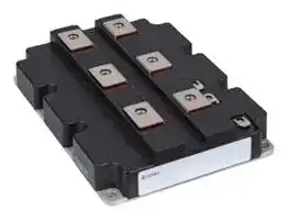


FZ2400R33HE4BPSA1
IGBT Module, Three level Inverter, 2.4 kA, 2.4 V, 150 °C, Module
- Manufacturer: INFINEON
- Product type: IGBT Modules
- SVHC: No SVHC (25-Jun-2025)
- Product Range: IHM-B
- IGBT Technology: IGBT 4 [Trench/Field Stop]
- IGBT Termination: Stud
- Power Dissipation: -
- IGBT Configuration: Three level Inverter
- Transistor Mounting: Panel
- DC Collector Current: 2.4kA
- Power Dissipation Pd: -
- Transistor Case Style: Module
- Operating Temperature Max: 150°C
- Junction Temperature Tj Max: 150°C
- Continuous Collector Current: 2.4kA
- Collector Emitter Voltage Max: 3.3kV
- Collector Emitter Voltage V(br)ceo: 3.3kV
- Collector Emitter Saturation Voltage: 2.4V
- Collector Emitter Saturation Voltage Vce(on): 2.4V
| Delivery and price | |
|---|---|
| Units per pack | 1 |
| Price | 1910.52 € |
| Current stock | 10+ |
| Lead time | 30 days |
**FZ2400R33HE4 IHM-B module**

## **IHM-B module with Trench/Fieldstop IGBT4 and Emitter Controlled 4 diode**

## **Features**

- Electrical features

- VCES = 3300 V

- IC nom = 2400 A / ICRM = 4800 A

- High current density

- High DC stability

- High short-circuit capability

- Low switching losses

- Low VCEsat

- T = 150 °C vj op

- Trench IGBT 4

- Unbeatable robustness

- VCEsat with positive temperature coefficient

- Low Qg and Cres

- Mechanical features

- AlSiC base plate for increased thermal cycling capability

- High power density

- Isolated base plate

- Package with CTI > 600

- RoHS compliant

## **Potential applications**

- High power converters

- Medium voltage converters

- Motor drives

- Traction drives

- UPS systems

- Active frontend (energy recovery)

- Commercial Agriculture Vehicles

## **Product validation**

- Qualified for industrial applications according to the relevant tests of IEC 60747, 60749 and 60068

## **Description**

Please read the Important Notice and Warnings at the end of this document

Datasheet **www.infineon.com**

1.00 2021-03-25

**FZ2400R33HE4 IHM-B module**

**==> picture [105 x 47] intentionally omitted <==**

## **Table of contents**

## **Table of contents**

||**Description**. . . . . . . . . . . . . . . . . . . . . . . . . . . . . . . . . . . . . . . . . . . . . . . . . . . . . . . . . . . . . . . . . . . . . . . . . . . . . . . . . . 1|
|---|---|
||**Features**. . . . . . . . . . . . . . . . . . . . . . . . . . . . . . . . . . . . . . . . . . . . . . . . . . . . . . . . . . . . . . . . . . . . . . . . . . . . . . . . . . . . .1|
||**Potential applications**. . . . . . . . . . . . . . . . . . . . . . . . . . . . . . . . . . . . . . . . . . . . . . . . . . . . . . . . . . . . . . . . . . . . . . . 1|
||**Product validation**. . . . . . . . . . . . . . . . . . . . . . . . . . . . . . . . . . . . . . . . . . . . . . . . . . . . . . . . . . . . . . . . . . . . . . . . . . . 1|
||**Table of contents**. . . . . . . . . . . . . . . . . . . . . . . . . . . . . . . . . . . . . . . . . . . . . . . . . . . . . . . . . . . . . . . . . . . . . . . . . . . . 2|
|**1**|**Package**. . . . . . . . . . . . . . . . . . . . . . . . . . . . . . . . . . . . . . . . . . . . . . . . . . . . . . . . . . . . . . . . . . . . . . . . . . . . . . . . . . . . . 3|
|**2**|**IGBT, Inverter**. . . . . . . . . . . . . . . . . . . . . . . . . . . . . . . . . . . . . . . . . . . . . . . . . . . . . . . . . . . . . . . . . . . . . . . . . . . . . . . .3|
|**3**|**Diode, Inverter**. . . . . . . . . . . . . . . . . . . . . . . . . . . . . . . . . . . . . . . . . . . . . . . . . . . . . . . . . . . . . . . . . . . . . . . . . . . . . . 5|
|**4**|**Characteristics diagrams**. . . . . . . . . . . . . . . . . . . . . . . . . . . . . . . . . . . . . . . . . . . . . . . . . . . . . . . . . . . . . . . . . . . . . 7|
|**5**|**Circuit diagram**. . . . . . . . . . . . . . . . . . . . . . . . . . . . . . . . . . . . . . . . . . . . . . . . . . . . . . . . . . . . . . . . . . . . . . . . . . . . . 11|
|**6**|**Package outlines**. . . . . . . . . . . . . . . . . . . . . . . . . . . . . . . . . . . . . . . . . . . . . . . . . . . . . . . . . . . . . . . . . . . . . . . . . . . .11|
||**Disclaimer**. . . . . . . . . . . . . . . . . . . . . . . . . . . . . . . . . . . . . . . . . . . . . . . . . . . . . . . . . . . . . . . . . . . . . . . . . . . . . . . . . .12|


Datasheet

2

1.00 2021-03-25

**FZ2400R33HE4 IHM-B module**

**==> picture [105 x 47] intentionally omitted <==**

## **1 Package**

## **1 Package**

|**1**<br>**Package**|**1**<br>**Package**|**1**<br>**Package**|**1**<br>**Package**|**1**<br>**Package**|
|---|---|---|---|---|
|**Table 1**<br>**Insulation coordination**|||||
|**Parameter**|**Symbol**|**Note or test condition**|**Values**|**Unit**|
|Isolation test voltage|_V_ISOL|RMS, f = 50 Hz|6.0|kV|
|Partial discharge extinction<br>voltage|_V_isol|RMS, f = 50 Hz, QPD≤ 10 pC|2.6|kV|
|DC stability|_V_CE(D)|Tvj=25°C, 100 Fit|2100|V|
|Material of module<br>baseplate|||AlSiC||
|Creepage distance|_d_Creep|terminal to heatsink|32.2|mm|
|Clearance|_d_Clear|terminal to heatsink|19.1|mm|
|Comparative tracking index|_CTI_||> 600||


**Table 2 Characteristic values**

|**Parameter**|**Symbol**|**Note or test condition**||**Values**|**Values**|**Values**|**Unit**|
|---|---|---|---|---|---|---|---|
|||||**Min.**|**Typ.**|**Max.**||
|Stray inductance module|_L_sCE||||6||nH|
|Module lead resistance,<br>terminals - chip|_R_AA'+CC'|TC=25°C, per switch|||0.08||mΩ|
|Module lead resistance,<br>terminals - chip|_R_CC'+EE'|TC=25°C, per switch|||0.095||mΩ|
|Storage temperature|_T_stg|||-40||150|°C|
|Mounting torque for modul<br>mounting|_M_|- Mounting according to<br>valid application note|M6, Screw|4.25||5.75|Nm|
|Terminal connection torque|_M_|- Mounting according to<br>valid application note|M4, Screw|1.8||2.1|Nm|
||||M8, Screw|8||10||
|Weight|_G_||||1200||g|


## **2 IGBT, Inverter**

## **Table 3 Maximum rated values**

|**Parameter**|**Symbol**|**Note or test condition**||**Values**|**Unit**|
|---|---|---|---|---|---|
|Collector-emitter voltage|_V_CES||_T_vj= -40 °C|3300|V|
||||_T_vj= 150 °C|3300||
|Continous DC collector<br>current|_I_CDC|_T_vj max= 150 °C|_T_C= 105 °C|2400|A|
|Repetitive peak collector<br>current|_I_CRM|_t_P= 1 ms||4800|A|
|Gate-emitter peak voltage|_V_GES|||±20|V|


Datasheet

3

1.00

2021-03-25

**FZ2400R33HE4 IHM-B module**

**==> picture [105 x 47] intentionally omitted <==**

## **2 IGBT, Inverter**

## **Characteristic values**

|||||||||
|---|---|---|---|---|---|---|---|
|**Table 4**<br>**Characteristic values**||||||||
|**Parameter**|**Symbol**|**Note or test condition**||**Values**|||**Unit**|
|||||**Min.**|**Typ.**|**Max.**||
|Collector-emitter saturation<br>voltage|_V_CE sat|_I_C= 2400 A,_V_GE= 15 V|_T_vj= 25 °C||2.40|2.65|V|
||||_T_vj= 125 °C||2.95|||
||||_T_vj= 150 °C||3.10|3.25||
|Gate threshold voltage|_V_GEth|_I_C= 94 mA, VCE= VGE,_T_vj=|25 °C|5.20|5.80|6.40|V|
|Gate charge|_Q_G|_V_GE= ±15 V,_V_CE= 1800 V|||40||µC|
|Internal gate resistor|_R_Gint|_T_vj= 25 °C|||0.5||Ω|
|Input capacitance|_C_ies|_f_= 1000 kHz,_T_vj= 25 °C,_V_CE= 25 V,_V_GE= 0 V|||280||nF|
|Reverse transfer capacitance|_C_res|_f_= 1000 kHz,_T_vj= 25 °C,_V_CE= 25 V,_V_GE= 0 V|||8||nF|
|Collector-emitter cut-of<br>current|_I_CES|_V_CE= 3300 V,_V_GE= 0 V|_T_vj= 25 °C|||5|mA|
|Gate-emitter leakage current|_I_GES|_V_CE= 0 V,_V_GE= 20 V,_T_vj= 25 °C||||400|nA|
|Turn-on delay time<br>(inductive load)|_t_don|_I_C= 2400 A,_V_CE= 1800 V,<br>_V_GE= ±15 V,_R_Gon= 0.5 Ω|_T_vj= 25 °C||0.560||µs|
||||_T_vj= 125 °C||0.660|||
||||_T_vj= 150 °C||0.670|||
|Rise time (inductive load)|_t_r|_I_C= 2400 A,_V_CE= 1800 V,<br>_V_GE= ±15 V,_R_Gon= 0.5 Ω|_T_vj= 25 °C||0.250||µs|
||||_T_vj= 125 °C||0.270|||
||||_T_vj= 150 °C||0.290|||
|Turn-of delay time<br>(inductive load)|_t_dof|_I_C= 2400 A,_V_CE= 1800 V,<br>_V_GE= ±15 V,_R_Gof= 3.3 Ω|_T_vj= 25 °C||4.000||µs|
||||_T_vj= 125 °C||4.300|||
||||_T_vj= 150 °C||4.300|||
|Fall time (inductive load)|_t_f|_I_C= 2400 A,_V_CE= 1800 V,<br>_V_GE= ±15 V,_R_Gof= 3.3 Ω|_T_vj= 25 °C||0.540||µs|
||||_T_vj= 125 °C||1.180|||
||||_T_vj= 150 °C||1.400|||
|Turn-on energy loss per<br>pulse|_E_on|_I_C= 2400 A,_V_CE= 1800 V,<br>_L_σ= 85 nH,_V_GE= ±15 V,<br>_R_Gon= 0.5 Ω, di/dt =<br>7600 A/µs (Tvj= 150 °C)|_T_vj= 25 °C||2000||mJ|
||||_T_vj= 125 °C||3400|||
||||_T_vj= 150 °C||3900|||
|Turn-of energy loss per<br>pulse|_E_of|_I_C= 2400 A,_V_CE= 1800 V,<br>_L_σ= 85 nH,_V_GE= ±15 V,<br>_R_Gof= 3.3 Ω, dv/dt =<br>1500 V/µs (Tvj= 150 °C)|_T_vj= 25 °C||3500||mJ|
||||_T_vj= 125 °C||4600|||
||||_T_vj= 150 °C||4950|||
|SC data|_I_SC|_V_GE≤  15 V,_V_CC= 2400 V,<br>VCEmax=VCES-LsCE*di/dt|_t_P≤  10 µs,_T_vj≤<br>150 °C||9600||A|
|Thermal resistance, junction<br>to case|_R_thJC|per IGBT||||5.50|K/kW|


Datasheet

1.00

4

2021-03-25

**FZ2400R33HE4 IHM-B module**

**==> picture [105 x 47] intentionally omitted <==**

## **3 Diode, Inverter**

|**Table 4**<br>**Characteristic values (continued)**|**Table 4**<br>**Characteristic values (continued)**|**Table 4**<br>**Characteristic values (continued)**|||||
|---|---|---|---|---|---|---|
|**Parameter**|**Symbol**|**Note or test condition**|**Values**|||**Unit**|
||||**Min.**|**Typ.**|**Max.**||
|Thermal resistance, case to<br>heatsink|_R_thCH|per IGBT,λgrease= 1 W/(m*K)||4.30||K/kW|
|Temperature under<br>switching conditions|_T_vj op||-40||150|°C|


## **3 Diode, Inverter**

|**3**<br>**Diode, Inverter**|**3**<br>**Diode, Inverter**|**3**<br>**Diode, Inverter**||||
|---|---|---|---|---|---|
|**Table 5**<br>**Maximum rated values**||||||
|**Parameter**|**Symbol**|**Note or test condition**||**Values**|**Unit**|
|Repetitive peak reverse<br>voltage|_V_RRM||_T_vj= -40 °C|3300|V|
||||_T_vj= 150 °C|3300||
|Continous DC forward<br>current|_I_F|||2400|A|
|Repetitive peak forward<br>current|_I_FRM|_t_P= 1 ms||4800|A|
|I2t - value|_I_2_t_|_t_P= 10 ms,_V_R= 0 V|_T_vj= 125 °C|1230|kA²s|
||||_T_vj= 150 °C|1110||
|Maximum power dissipation|_P_RQM|_T_vj= 150 °C||5400|kW|
|Minimum turn-on time|_t_onmin|||10|µs|


**Table 6 Characteristic values**

|**Parameter**|**Symbol**|**Note or test condition**||**Values**|**Values**|**Values**|**Unit**|
|---|---|---|---|---|---|---|---|
|||||**Min.**|**Typ.**|**Max.**||
|Forward voltage|_V_F|_I_F= 2400 A,_V_GE= 0 V|_T_vj= 25 °C||2.90|3.30|V|
||||_T_vj= 125 °C||2.60|||
||||_T_vj= 150 °C||2.50|2.80||
|Peak reverse recovery<br>current|_I_RM|_V_R= 1800 V,_I_F= 2400 A,<br>_V_GE= -15 V, -diF/dt =<br>7600 A/µs (Tvj= 150 °C)|_T_vj= 25 °C||2440||A|
||||_T_vj= 125 °C||2820|||
||||_T_vj= 150 °C||2880|||
|Recovered charge|_Q_r|_V_R= 1800 V,_I_F= 2400 A,<br>_V_GE= -15 V, -diF/dt =<br>7600 A/µs (Tvj= 150 °C)|_T_vj= 25 °C||1100||µC|
||||_T_vj= 125 °C||2100|||
||||_T_vj= 150 °C||2500|||
|Reverse recovery energy|_E_rec|_V_R= 1800 V,_I_F= 2400 A,<br>_V_GE= -15 V, -diF/dt =<br>7600 A/µs (Tvj= 150 °C)|_T_vj= 25 °C||1480||mJ|
||||_T_vj= 125 °C||2750|||
||||_T_vj= 150 °C||3200|||


Datasheet

1.00

5

2021-03-25

**FZ2400R33HE4 IHM-B module**

**==> picture [105 x 47] intentionally omitted <==**

## **3 Diode, Inverter**

|**Table 6**<br>**Characteristic values (continued)**|**Table 6**<br>**Characteristic values (continued)**|**Table 6**<br>**Characteristic values (continued)**|||||
|---|---|---|---|---|---|---|
|**Parameter**|**Symbol**|**Note or test condition**|**Values**|||**Unit**|
||||**Min.**|**Typ.**|**Max.**||
|Thermal resistance, junction<br>to case|_R_thJC|per diode|||10.6|K/kW|
|Thermal resistance, case to<br>heatsink|_R_thCH|per diode,λgrease= 1 W/(m*K)||5.10||K/kW|
|Temperature under<br>switching conditions|_T_vj op||-40||150|°C|


Datasheet

6

1.00 2021-03-25

**FZ2400R33HE4 IHM-B module**

**4 Characteristics diagrams**

**==> picture [105 x 47] intentionally omitted <==**

## **4 Characteristics diagrams**

**output characteristic (typical), IGBT, Inverter** IC = f(VCE) VGE = 15 V

**output characteristic (typical), IGBT, Inverter** IC = f(VCE) T = 150 °C vj

**==> picture [539 x 572] intentionally omitted <==**

**----- Start of picture text -----**<br>
4800 4800<br>4400 4400<br>4000 4000<br>3600 3600<br>3200 3200<br>2800 2800<br>2400 2400<br>2000 2000<br>1600 1600<br>1200 1200<br>800 800<br>400 400<br>0 0<br>0.0 0.5 1.0 1.5 2.0 2.5 3.0 3.5 4.0 4.5 5.0 0.0 0.5 1.0 1.5 2.0 2.5 3.0 3.5 4.0 4.5 5.0<br>transfer characteristic (typical), IGBT, Inverter switching losses (typical), IGBT, Inverter<br>IC = f(VGE) E = f(IC)<br>VCE = 20 V RGoff = 3.3 Ω, RGon = 0.5 Ω, VCE = 1800 V, VGE = ± 15 V<br>4800 12000<br>4400 11000<br>4000 10000<br>3600 9000<br>3200 8000<br>2800 7000<br>2400 6000<br>2000 5000<br>1600 4000<br>1200 3000<br>800 2000<br>400 1000<br>0 0<br>5 6 7 8 9 10 11 12 13 0 600 1200 1800 2400 3000 3600 4200 4800<br>**----- End of picture text -----**<br>


Datasheet

1.00 2021-03-25

7

**FZ2400R33HE4 IHM-B module**

**==> picture [105 x 47] intentionally omitted <==**

## **4 Characteristics diagrams**

## **switching losses (typical), IGBT, Inverter** E = f(RG)

IC = 2400 A, VCE = 1800 V, VGE = ± 15 V

**==> picture [228 x 253] intentionally omitted <==**

**----- Start of picture text -----**<br>
18000<br>16000<br>14000<br>12000<br>10000<br>8000<br>6000<br>4000<br>2000<br>0<br>0 1 2 3 4 5 6<br>**----- End of picture text -----**<br>


**switching times (typical), IGBT, Inverter** t = f(RG) IC = 2400 A, VCE = 1800 V, VGE = ± 15 V, Tvj = 125 °C

**==> picture [228 x 252] intentionally omitted <==**

**----- Start of picture text -----**<br>
10<br>1<br>0.1<br>0 1 2 3 4 5 6<br>**----- End of picture text -----**<br>


**switching times (typical), IGBT, Inverter** t = f(IC) RGoff = 3.3 Ω, RGon = 0.5 Ω, VCE = 1800 V, VGE = ± 15 V, Tvj = 125 °C

**==> picture [229 x 253] intentionally omitted <==**

**----- Start of picture text -----**<br>
10<br>1<br>0.1<br>0.01<br>0 600 1200 1800 2400 3000 3600 4200 4800<br>**----- End of picture text -----**<br>


## **transient thermal impedance , IGBT, Inverter** Zth = f(t)

**==> picture [229 x 252] intentionally omitted <==**

**----- Start of picture text -----**<br>
10<br>1<br>0.1<br>0.01<br>0.001 0.01 0.1 1 10<br>**----- End of picture text -----**<br>


Datasheet

8

1.00 2021-03-25

**FZ2400R33HE4 IHM-B module**

**==> picture [105 x 47] intentionally omitted <==**

## **4 Characteristics diagrams**

## **reverse bias safe operating area (RBSOA), IGBT, Inverter**

IC = f(VCE)

**capacity characteristic (typical), IGBT, Inverter** C = f(VCE)

f = 100 kHz, VGE = 0 V, Tvj = 25 °C

RGoff = 3.3 Ω, VGE = 15 V, Tvj = 150 °C

**==> picture [539 x 311] intentionally omitted <==**

**----- Start of picture text -----**<br>
6000 500<br>5400<br>4800 400<br>4200<br>3600 300<br>3000<br>2400 200<br>1800<br>1200 100<br>600<br>0 0<br>0 500 1000 1500 2000 2500 3000 3500 0.1 1 10 100<br>gate charge characteristic (typical), IGBT, Inverter forward characteristic of (typical), Diode, Inverter<br>VGE = f(QG) IF = f(VF)<br>IC = 2400 A, Tvj = 25 °C<br>**----- End of picture text -----**<br>


**==> picture [539 x 262] intentionally omitted <==**

**----- Start of picture text -----**<br>
4800<br>14<br>4400<br>12<br>10 4000<br>8<br>3600<br>6<br>3200<br>4<br>2800<br>2<br>0 2400<br>-2<br>2000<br>-4<br>1600<br>-6<br>1200<br>-8<br>-10 800<br>-12<br>400<br>-14<br>0<br>0 4 8 12 16 20 24 28 32 36 40 0.0 0.4 0.8 1.2 1.6 2.0 2.4 2.8 3.2 3.6 4.0<br>**----- End of picture text -----**<br>


Datasheet

9

1.00 2021-03-25

**FZ2400R33HE4 IHM-B module**

**==> picture [105 x 47] intentionally omitted <==**

## **4 Characteristics diagrams**

## **switching losses (typical), Diode, Inverter**

Erec = f(IF)

VCE = 1800 V, RGon = RGon(IGBT)

## **switching losses (typical), Diode, Inverter**

Erec = f(RG) VCE = 1800 V, IF = 2400 A

**==> picture [539 x 572] intentionally omitted <==**

**----- Start of picture text -----**<br>
5000 4000<br>4500<br>3500<br>4000<br>3000<br>3500<br>2500<br>3000<br>2500 2000<br>2000<br>1500<br>1500<br>1000<br>1000<br>500<br>500<br>0 0<br>0 600 1200 1800 2400 3000 3600 4200 4800 0 1 2 3 4 5 6<br>transient thermal impedance , Diode, Inverter safe operation area (SOA), Diode, Inverter<br>Zth = f(t) IR = f(VR)<br>T  = 150 °C<br>vj<br>100 5400<br>4800<br>4200<br>10 3600<br>3000<br>2400<br>1 1800<br>1200<br>600<br>0.1 0<br>0.001 0.01 0.1 1 10 0 500 1000 1500 2000 2500 3000 3500<br>**----- End of picture text -----**<br>


Datasheet

10

1.00 2021-03-25

**FZ2400R33HE4 IHM-B module**

**==> picture [105 x 47] intentionally omitted <==**

## **5 Circuit diagram**

**==> picture [167 x 14] intentionally omitted <==**

**----- Start of picture text -----**<br>
5 Circuit diagram<br>**----- End of picture text -----**<br>


**Figure 2**

**==> picture [177 x 14] intentionally omitted <==**

**----- Start of picture text -----**<br>
6 Package outlines<br>**----- End of picture text -----**<br>


**==> picture [72 x 68] intentionally omitted <==**

**==> picture [52 x 49] intentionally omitted <==**

**==> picture [100 x 56] intentionally omitted <==**

**==> picture [52 x 49] intentionally omitted <==**

**Figure 3**

Datasheet

1.00 2021-03-25

11

## **Trademarks**

All referenced product or service names and trademarks are the property of their respective owners.

**Edition 2021-03-25 IMPORTANT NOTICE Published by** The information given in this document shall in no event be regarded as a guarantee of conditions or **Infineon Technologies AG** characteristics (“Beschaffenheitsgarantie”). **81726 Munich, Germany**

With respect to any examples, hints or any typical values stated herein and/or any information regarding **© 2021 Infineon Technologies AG** the application of the product, Infineon Technologies hereby disclaims any and all warranties and liabilities **All Rights Reserved.** of any kind, including without limitation warranties of non-infringement of intellectual property rights of any **Do you have a question about any** third party. **aspect of this document?** In addition, any information given in this document is **Email: erratum@infineon.com** subject to customer’s compliance with its obligations stated in this document and any applicable legal requirements, norms and standards concerning **Document reference** customer’s products and any use of the product of **IFX-** Infineon Technologies in customer’s applications.

Please note that this product is not qualified according to the AEC Q100 or AEC Q101 documents of the Automotive Electronics Council.

## **WARNINGS**

Due to technical requirements products may contain dangerous substances. For information on the types in question please contact your nearest Infineon Technologies office.

Except as otherwise explicitly approved by Infineon Technologies in a written document signed by authorized representatives of Infineon Technologies, Infineon Technologies’ products may not be used in any applications where a failure of the product or any consequences of the use thereof can reasonably be expected to result in personal injury.

The data contained in this document is exclusively intended for technically trained staff. It is the responsibility of customer’s technical departments to evaluate the suitability of the product for the intended application and the completeness of the product information given in this document with respect to such application.
Updated at April 28, 2026
Infineon Technologies is a globally recognized leader in semiconductor solutions, renowned for driving innovation in power management, energy efficiency, and modern mobility. With a strong legacy of engineering excellence, the company provides highly reliable components designed to meet the rigorous demands of industrial, automotive, and advanced commercial applications. The core of our Infineon portfolio is centered on their industry-leading discrete semiconductors. We offer an extensive selection of single and dual MOSFETs, alongside a robust range of single IGBTs and advanced IGBT modules. These flagship power transistors are essential for high-efficiency power conversion and motor control, providing engineers with superior thermal performance and minimized switching losses. Beyond advanced field-effect transistors, the selection includes a comprehensive array of diodes and rectifiers, heavily featuring Schottky diodes, as well as fast-recovery and RF/PIN diodes. This power foundation is further supported by bipolar transistors, intelligent power modules, and thyristor SCR modules, delivering the critical building blocks required for complex power system designs. To support broader system integration, the portfolio also encompasses specialized solutions such as solid-state relays, AC/DC LED driver ICs, and Bluetooth communications modules. From high-power industrial rectifiers to wireless connectivity adapters, Infineon equips designers with the precision components needed to build efficient, scalable, and fully connected electronic systems.
About Novapart
Novapart is a B2B electronic component broker specialising in stock shortages and cost reduction. We source hard-to-find parts and identify compliant alternatives across a catalogue of 410,000+ components from 500+ manufacturers.
Learn more →Stock Shortage Specialist
When a component is unavailable, discontinued or has an unacceptable lead time, we tap into our network of vetted European and Asian distributors to source what you need — without compromising on quality or traceability.
Request a quote →Compliant Alternatives
We identify pin-to-pin, electrically equivalent substitutes that meet the same certifications (RoHS, AEC-Q100, REACH) as your original specification — validated against datasheets, not just part numbers. Often at a lower cost.
BOM Analysis service →