
Image not available
Illustrative purposes only

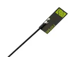
FXP840.07.0055B
PCB Antenna, 4.9GHz to 6GHz, 2.5 VSWR, 2.5dBi Gain, 50ohm, Linear Polarisation, Adhesive
⚠️ Reference pricing provided. In case of supply shortages, we will connect you with our trusted procurement partners to ensure your project's continuity.
- Manufacturer: TAOGLAS
- Product type:
- Antenna Type:PCB; Frequency Min:4.9GHz; Frequency Max:6GHz; Antenna Mounting:Adhesive; Gain:2.5dBi; VSWR:2.5; Input Power:2W; Input Impedance:50ohm; Antenna Polarisation:Linear; Product Ran
- Gain: 2.5dBi
- SVHC: To Be Advised
- VSWR: 2.5
- Input Power: 2W
- Antenna Type: PCB
- Frequency Max: 6GHz
- Frequency Min: 4.9GHz
- Product Range: Freedom
- Input Impedance: 50ohm
- Antenna Mounting: Adhesive
- Antenna Polarisation: Linear
| Delivery and price | |
|---|---|
| Units per pack | 250 |
| Price | 4.62 € |
| Current stock | 50+ |
| Lead time | 30 days |
Datasheet

## **Specification**

## **Patent Pending**

Part No. : **FXP840.07.0055B**

Product Name

: FXP840 Freedom Series Super Small Monopole Dual-band 2.4 GHz and 4.9-6GHz Antenna

Features

- : Flexible and Tiny - Ultra Low Profile 14*5*0.1mm 2dBi Peak Gain

Adheres directly inside of product plastic or glass housing Form factor and cable routing convenient for integration IPEX MHF1 Connector (U.FL compatible) 55mm  Ø 0.81mm mini-coaxial cable Customizable cable and connector

**RoHS Compliant**

SPE-12-8-115/H/EZ      Page 1 of 14

## **1. Introduction**

The patent pending FXP840 is a super small monopole ultra-low profile antenna for 2.4/4.9-6 GHz.  This antenna is designed for DSRC, V2V, WiFi, Bluetooth, ZigBee and other applications in these bands. The FXP840 has a peak gain of 2.5dBi at 2.4GHz and efficiencies of 40%, and 2.5dBi gain and 53% efficiency at 5.8GHz.

This Taoglas patent pending antenna is unique in the market because it is made from polyflexible material, has a tiny form factor (14mm*5.0mm*0.1mm) and has double-sided 3M tape for easy “peel and stick” mounting.

The cable routes conveniently directly out of the bottom of the antenna, reducing the volume the antenna takes up in the device to an absolute minimum compared to other designs. The FXP840 is the ideal all-round antenna solution for fitting into narrow spaces and still maintaining high performance, for example on the inside top or adjacent side applied directly to the plastic housing of LCD monitors, tablets, smartphones.

The cable and connector are customizable according to customer requirements.

Many module manufacturers specify peak gain limits for any antennas that are to be connected to that module. Those peak gain limits are based on free-space conditions. In practice, the peak gain of an antenna tested in free-space can degrade by at least 1 or 2dBi when put inside a device. So ideally you should go for a slightly higher peak gain antenna than mentioned on the module specification to compensate for this effect, giving you better performance.

Upon testing of any of our antennas with your device and a selection of appropriate layout, integration technique, or cable, Taoglas can make sure any of our antennas’ peak gain will be below the peak gain limits. Taoglas can then issue a specification and/or report for the selected antenna in your device that will clearly show it complying with the peak gain limits, so you can be assured you are meeting regulatory requirements for that module.

For example, a module manufacturer may state that the antenna must have less than 2dBi peak gain, but you don’t need to select an embedded antenna that has a peak gain of less than 2dBi in free-space. This will give you a less optimized solution. It is better to go for a slightly higher free-space peak gain of 3dBi or more if available. Once that antenna gets integrated into your device, performance will degrade below this 2dBi peak gain due to the effects of GND plane, surrounding components, and device housing. If you want to be absolutely sure, contact Taoglas and we will test. Choosing a Taoglas antenna with a higher peak gain than what is specified by the module manufacturer and enlisting our help will ensure you are getting the best performance possible without exceeding the peak gain limits.

SPE-12-8-115/H/EZ      Page 2 of 14

## **2. Specification**

|**Standard**<br>Operation Frequency (MHz)<br>~~ss~~|**2400 MHz**<br>**5800 MHz**<br>2410-2490 MHz<br>4900~6000 MHz<br>~~ss eee~~|**2400 MHz**<br>**5800 MHz**<br>2410-2490 MHz<br>4900~6000 MHz<br>~~ss eee~~|
|---|---|---|
|Polarization|Linear|Linear|
|Impedance|50 Ohms|50 Ohms|
|Max VSWR|2:1|2.5:1|
|Max Return Loss (dB)|-10|-7.0|
|Peak Gain (dBi)|2.4|2.5|
|Efficiency (%)|40|53|
|Average Gain (dB)|-3.9|-2.8|
|Radiation Properties|Omni|Omni|
|Max Input Power|2W max|2W max|


* The FXP840 antenna performance was measured on a 30x30mm, 2mm thick ABS plastic plane.

|Dimensions (mm)<br>~~LT~~|14 x 5.0 x 0.1<br>~~LT~~|
|---|---|
|Required Space (mm)|14 x 5.0 x 0.1|
|Material|Polymer|
|Connector|IPEX MHF1|


|Operation Temperature|-40°C to 85°C|
|---|---|
|Storage Temperature|-40°C to 85°C|
|Relative Humidity|40% to 95%|
|RoHs Compliant|Yes|


SPE-12-8-115/H/EZ      Page 3 of 14

## **3. Antenna Characteristics**

## **3.1 Test set-up**

**==> picture [42 x 37] intentionally omitted <==**

**----- Start of picture text -----**<br>
Y<br>Z  X<br>**----- End of picture text -----**<br>


**Figure 1.** Impedance measurements (left side) and peak gain, efficiency and radiation pattern measurements (right side).

SPE-12-8-115/H/EZ      Page 4 of 14

## **3.2 Return Loss**

**Figure 2.** Return loss of the FXP840 antenna from 2100 MHz to 2700 MHz.

**Figure 3.** Return loss of the FXP840 antenna from 4500 MHz to 6000 MHz.

SPE-12-8-115/H/EZ      Page 5 of 14

## **3.3 VSWR**

**Figure 4.** VSWR of the FXP840 antenna from 2100 MHz to 2700 MHz.

**Figure 5.** VSWR of the FXP840 antenna from 4500 MHz to 6000 MHz

SPE-12-8-115/H/EZ      Page 6 of 14

## **3.4 Efficiency**

**Figure 6.** Efficiency of the FXP840 antenna from 2300 MHz to 2700 MHz.

**Figure 7.** Efficiency of the FXP840 antenna from 4800 MHz to 6000 MHz.

SPE-12-8-115/H/EZ      Page 7 of 14

## **3.5 Peak Gain**

**Figure 8** Peak Gain of the FXP840 antenna from 2300 MHz to 2700 MHz.

**Figure 9.** Peak Gain of the FXP840 antenna from 4800 MHz to 6000 MHz.

SPE-12-8-115/H/EZ      Page 8 of 14

## **3.6 3D Radiation Patterns**

**Figure 12.** 3D Radiation Pattern at 2450 MHz (left side), Radiation Pattern at 5000 MHz (right side) of the FXP840 Antenna.

**3.7 2D Radiation Patterns**

SPE-12-8-115/H/EZ      Page 9 of 14

**Figure 13.** 2D Radiation Pattern at 2400MHz band

SPE-12-8-115/H/EZ      Page 10 of 14

**Figure 14.** 2D Radiation Pattern at 5800MHz band

SPE-12-8-115/H/EZ      Page 11 of 14

## **4. Antenna Drawing**

**Figure 15.** Antenna drawing

SPE-12-8-115/H/EZ      Page 12 of 14

## **5. Packaging**

**Figure 16.** Package of the FXP840 Antenna.

SPE-12-8-115/H/EZ      Page 13 of 14

_Taoglas makes no warranties based on the accuracy or completeness of the contents of this document and reserves the right to make changes to specifications and product descriptions at any time without notice._

_Taoglas reserves all rights to this document and the information contained herein. Reproduction, use or disclosure to third parties without express permission is strictly prohibited._

_Copyright © 2015, Taoglas Ltd._

SPE-12-8-115/H/EZ      Page 14 of 14
Updated at June 9, 2026
About Novapart
Novapart is a B2B electronic component broker specialising in stock shortages and cost reduction. We source hard-to-find parts and identify compliant alternatives across a catalogue of 410,000+ components from 500+ manufacturers.
Learn more →Stock Shortage Specialist
When a component is unavailable, discontinued or has an unacceptable lead time, we tap into our network of vetted European and Asian distributors to source what you need — without compromising on quality or traceability.
Request a quote →Compliant Alternatives
We identify pin-to-pin, electrically equivalent substitutes that meet the same certifications (RoHS, AEC-Q100, REACH) as your original specification — validated against datasheets, not just part numbers. Often at a lower cost.
BOM Analysis service →