
Image not available
Illustrative purposes only

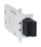
FX3U-485-BD
INTERFACE ADAPTER, RS485, 5VDC
⚠️ Reference pricing provided. In case of supply shortages, we will connect you with our trusted procurement partners to ensure your project's continuity.
- Manufacturer: MITSUBISHI
- Product type: Controller Accessories
- SVHC: No SVHC (15-Jan-2018)
- Product Range: MELSEC FX3U
- Current Rating: 40mA
| Delivery and price | |
|---|---|
| Units per pack | 1 |
| Price | 143.35 € |
| Current stock | 10+ |
| Lead time | 30 days |
Datasheet

## **•EFX3UƒVƒŠ•[ƒYAdditional Product Support Version**
- **FX3U Series**
- **Inverter Communication**
- **(F700/A700 Series)**
- **N:N Network**
- **Parallel Link**
- **Computer Link**
- **Inverter Communication**
- **Non-Protocol Communication**
- **Programming Communication**
- • **Remote Maintenance**
## **FX SERIES PROGRAMMABLE CONTROLLERS**
## **RS-232C Interface** SSS
FX3U-232-BD FX3U-232ADP FX2N-232-BD FX2NC-232ADP FX1N-232-BD FX0N-232ADP FX-232ADP FX2N-232IF
## **RS-485 Interface**
FX3U-485-BD FX3U-485ADP FX2N-485-BD FX2NC-485ADP FX1N-485-BD FX0N-485ADP FX-485ADP
## **RS-485/232C Converter**
FX-485PC-IF
## **RS-422 Interface**
FX3U-422-BD FX2N-422-BD FX1N-422-BD
## **USB Interface**
FX3U-USB-BD
## **Safety Precautions**
(Read these precautions before use.)
Before installing, operating, maintenance or inspecting this product, thoroughly read and understand this manual and the associated manuals. Also pay careful attention to handle the module properly and safety.
This manual classifies the safety precautions into two categories: and .
**==> picture [115 x 70] intentionally omitted <==**
Indicates that incorrect handling may cause hazardous conditions, resulting in death or severe injury.
Indicates that incorrect handling may cause hazardous conditions, resulting in medium or slight personal injury or physical damage.
Depending on circumstances, procedures indicated by may also be linked to serious results. In any case, it is important to follow the directions for usage.
Store this manual in a safe place so that you can take it out and read it whenever necessary. Always forward it to the end user.
## **1. DESIGN PRECAUTIONS**
**==> picture [457 x 37] intentionally omitted <==**
- Provide a safety circuit on the outside of the PLC so that the whole system operates to ensure the safety even when external power supply trouble, PLC failure, or communication error occurs. Otherwise, malfunction or output failures may result in an accident.
- 1) An emergency stop circuit, a protection circuit, an interlock circuit for opposite movements, such as normal and reverse rotations, and an interlock circuit for preventing damage to the machine at the upper and lower positioning limits should be configured on the outside of the PLC.
- 2) When the PLC CPU detects an error, such as a watchdog timer error, during self-diagnosis, all outputs are turned off. When an error that cannot be detected by the PLC CPU occurs in an input/output control block, output control may be disabled. Design external circuits and mechanisms to ensure safe operations of the machine in such a case.
- 3) The output current of the service power supply for sensor varies depending on the model and the absence/ presence of extension blocks. If overload is applied, the voltage automatically drops, inputs in the PLC are disabled, and all outputs are turned off. Design external circuits and mechanisms to ensure safe operations of the machine in such a case.
- 4) When some sort of error occurs in a relay, triac or transistor of the output unit, output may be kept on or off. For output signals that may lead to serious accidents, design external circuits and mechanisms to ensure safe operations of the machine in such cases.
**==> picture [457 x 37] intentionally omitted <==**
- Do not bundle the control line together with the main circuit or power line. Do not lay the control line near them.As a rule, lay the control line at least 100mm(3.94") or more away from the main circuit or power line. Noise may cause malfunctions.
- Use the product in such a status that excessive force is not applied on the built-in programming board, power connectors, I/O connectors, communication connectors, and communication cables. Failure to do so may result in wire breakage or failure of the PLC.
(1)
## **Safety Precautions**
(Read these precautions before use.)
## **2. WIRING PRECAUTIONS**
**==> picture [457 x 37] intentionally omitted <==**
- Cut off all phases of the power source externally before installation or wiring work in order to avoid electric shock or damage of product.
- • Make sure to attach the terminal cover offered as an accessory to the product before turning on the power or starting the operation after installation or wiring work. Failure to do so may cause electric shock.
**==> picture [457 x 37] intentionally omitted <==**
- Make sure to observe the precautions below in order to prevent any damage to the machine or any accident which may be caused by abnormal data written to the PLC due to the influence of noise: 1) Do not lay close or bundle with the main circuit line, high-voltage line, or load line. Otherwise, effects of noise or surge induction are likely to take place. Keep a safe distance of least 100 mm (3.94") from the above lines during wiring.
- 2) Ground the shield wire or shield of a shielded cable at one point on the PLC. However, do not ground at the same point as high voltage lines.
- • Perform wiring properly to the FX0N/FX2N Series extension equipment of the terminal block type in accordance with the precautions below. Failure to do so may cause electric shock, short-circuit, wire breakage, or damages to the product. - The disposal size of the cable end should follow the dimensions described in this manual.
- - Tightening torque should follow the torque described in this manual.
- • Observe the following items to wire the lines to the European terminal board. Ignorance of the following items may cause electric shock, short circuit, disconnection, or damage of the product. - The disposal size of the cable end should follow the dimensions described in this manual.
- - Tightening torque should follow the torque described in this manual.
- - Twist the end of strand wire and make sure there is no loose wires. - Do not solder-plate the electric wire ends.
- - Do not connect electric wires of unspecified size or beyond the specified number of electric wires.
- - Fix the electric wires so that the terminal block and connected parts of electric wires are not directly stressed.
## **3. STARTUP AND MAINTENANCE PRECAUTIONS**
**==> picture [457 x 37] intentionally omitted <==**
• Do not touch any terminal while the PLC's power is on. Doing so may cause electrical shock or malfunctions. • Before cleaning or retightening terminals, externally cut off all phases of the power supply. Failure to do so may expose you to shock hazard. • Before modifying the program under operation or performing operation for forcible output, running or stopping, carefully read the manual, and sufficiently ensure the safety. An operation error may damage the machine or cause accidents. • Do not change programs in the PLC from two or more peripheral equipment (such as the programming tool and GOT) at the same time. Such changes may cause destruction or malfunction of programs in the PLC.
**==> picture [457 x 37] intentionally omitted <==**
• Do not disassemble or modify the PLC. Doing so may cause failures, malfunctions or fire. For repair, contact your local Mitsubishi Electric distributor. • Before connecting or disconnecting any extension cable, turn off power. Failure to do so may cause unit failure or malfunctions. • Make sure to turn off the power before attaching or removing the peripheral equipment, expansion board, special adaptor, or function extension memory cassette. Failure to do so may cause device failure or malfunctions.
(2)
FX Series PLC User's Manual - Data Communication Edition
**==> picture [499 x 114] intentionally omitted <==**
# **FX Series Programmable Controllers User's Manual [Data Communication Edition]**
**==> picture [499 x 114] intentionally omitted <==**
|Manual number|JY997D16901|
|---|---|
|Manual revision|A|
|Date|7/2005|
## **Foreword**
This manual explains the "serial communication" provided in MELSEC-F FX Series Programmable Controllers and should be read and understood before attempting to install or use the unit. Store this manual in a safe place so that you can take it out and read it whenever necessary. Always forward it to the end user.
This manual confers no industrial property rights or any rights of any other kind, nor does it confer any patent licenses. Mitsubishi Electric Corporation cannot be held responsible for any problems involving industrial property rights which may occur as a result of using the contents noted in this manual.
© 2005 MITSUBISHI ELECTRIC CORPORATION
**1**
FX Series PLC User's Manual - Data Communication Edition
## **Outline Precautions**
- This manual provides information for the use of the FX3U Series Programmable Controllers. The manual has been written to be used by trained and competent personnel. The definition of such a person or persons is as follows;
- 1) Any engineer who is responsible for the planning, design and construction of automatic equipment using the product associated with this manual should be of a competent nature, trained and qualified to the local and national standards required to fulfill that role. These engineers should be fully aware of all aspects of safety with regards to automated equipment.
- 2) Any commissioning or service engineer must be of a competent nature, trained and qualified to the local and national standards required to fulfill that job. These engineers should also be trained in the use and maintenance of the completed product. This includes being completely familiar with all associated documentation for the said product. All maintenance should be carried out in accordance with established safety practices.
- 3) All operators of the completed equipment should be trained to use that product in a safe and coordinated manner in compliance to established safety practices. The operators should also be familiar with documentation which is connected with the actual operation of the completed equipment.
- **Note:** the term 'completed equipment' refers to a third party constructed device which contains or uses the product associated with this manual
- This product has been manufactured as a general-purpose part for general industries, and has not been designed or manufactured to be incorporated in a device or system used in purposes related to human life.
- Before using the product for special purposes such as nuclear power, electric power, aerospace, medicine or passenger movement vehicles, consult with Mitsubishi Electric.
- This product has been manufactured under strict quality control. However when installing the product where major accidents or losses could occur if the product fails, install appropriate backup or failsafe functions in the system.
- When combining this product with other products, please confirm the standard and the code, or regulations with which the user should follow. Moreover, please confirm the compatibility of this product to the system, machine, and apparatus with which a user is using.
- If in doubt at any stage during the installation of the product, always consult a professional electrical engineer who is qualified and trained to the local and national standards. If in doubt about the operation or use, please consult the nearest Mitsubishi Electric distributor.
- Since the examples indicated by this manual, technical bulletin, catalog, etc. are used as a reference, please use it after confirming the function and safety of the equipment and system. Mitsubishi Electric will accept no responsibility for actual use of the product based on these illustrative examples.
- This manual content, specification etc. may be changed without a notice for improvement.
- The information in this manual has been carefully checked and is believed to be accurate; however, if you have noticed a doubtful point, a doubtful error, etc., please contact the nearest Mitsubishi Electric distributor.
## **Registration**
- Microsoft[®] and Windows[®] are either registered trademarks or trademarks of Microsoft Corporation in the United States and/or other countries.
- The company name and the product name to be described in this manual are the registered trademarks or trademarks of each company.
**2**
FX Series PLC User's Manual - Data Communication Edition
_Table of Contents_
## **Table of Contents**
||**SAFETY PRECAUTIONS .................................................................................................... 1**<br>Common Items|
|---|---|
||**1. Introduction**<br>**A-1**|
||1.1 Types of Communication Types...................................................................................................A-1<br>1.2 Outline and Features of Communication Types...........................................................................A-3<br>1.2.1 CC-Link Network ..........................................................................................................................A-3<br>1.2.2 N:N Network .................................................................................................................................A-4<br>1.2.3 Parallel Link..................................................................................................................................A-5<br>1.2.4 Computer Link ..............................................................................................................................A-6<br>1.2.5 Inverter Communication ...............................................................................................................A-7<br>1.2.6 Non-protocol Communication.......................................................................................................A-8<br>1.2.7 Programming Communication......................................................................................................A-9<br>1.2.8 Remote Maintenance .................................................................................................................A-11<br>1.2.9 CC-Link/LT Network ...................................................................................................................A-12<br>1.2.10 AS-i system ..............................................................................................................................A-13<br>1.2.11 Internet Mail Sending................................................................................................................A-14<br>1.2.12 Short Mail Sending ...................................................................................................................A-15|
||**2. Communication Types and Communication Equipment**<br>**A-17**|
||2.1 Relationship between Equipment and Communication Types...................................................A-17<br>2.2 Communication Equipment Applicability Map............................................................................A-18<br>2.2.1 FX3Uand FX3UCPLCs..............................................................................................................A-18<br>2.2.2 FX2Nand FX2NCPLCs..............................................................................................................A-20<br>2.2.3 FX1S, FX1N, and FX1NCPLCs ..................................................................................................A-22<br>2.2.4 FX0NPLCs .................................................................................................................................A-24<br>2.2.5 FX0, FX0S, FX2(FX), FX2C, and FX1PLCs (reference).............................................................A-24<br>2.3 Combination of Communication Equipment (Block Diagram)....................................................A-26<br>2.3.1 How to look at combination pages..............................................................................................A-26<br>2.3.2 For FX0NSeries .........................................................................................................................A-27<br>2.3.3 For FX1SSeries .........................................................................................................................A-29<br>2.3.4 For FX1NSeries .........................................................................................................................A-30<br>2.3.5 For FX1NCSeries.......................................................................................................................A-32<br>2.3.6 For FX2NSeries .........................................................................................................................A-34<br>2.3.7 For FX2NCSeries.......................................................................................................................A-36<br>2.3.8 For FX3USeries..........................................................................................................................A-38<br>2.3.9 For FX3UCSeries.......................................................................................................................A-40<br>2.3.10 For FX2(FX) and FX2CSeries (reference) ...............................................................................A-42|
||**3. Outline of Communication Setting in FX Series**<br>**A-43**|
||3.1 Setting Method...........................................................................................................................A-43<br>3.2 Communication Setting in Parameter Method (GX Developer) .................................................A-44<br>3.2.1 Operating procedure...................................................................................................................A-44<br>3.2.2 Correspondence between parameter setting and each communication network.......................A-45<br>3.3 Communication Setting in Parameter Method (FXGP/WIN) ......................................................A-46<br>3.3.1 Operating procedure...................................................................................................................A-46<br>3.3.2 Correspondence between parameter setting and each communication type.............................A-48<br>3.4 Extension of Ports (FX3U, FX3UC).............................................................................................A-49<br>3.4.1 Limitation when ch1 and ch2 are used at same time .................................................................A-50|
**3**
FX Series PLC User's Manual - Data Communication Edition
_Table of Contents_
||**4. Introduction of Manuals (Type, Reading Method and Acquisition Method)**<br>**A-51**|
|---|---|
||4.1 Rank and Use Method of This Manual.......................................................................................A-51<br>4.2 Introduction of Related Manuals ................................................................................................A-52<br>4.2.1 Manual for communication types in FX PLCs.............................................................................A-52<br>4.2.2 Manuals related to FX PLCs.......................................................................................................A-52<br>4.2.3 Communication equipment (option)............................................................................................A-53<br>4.2.4 Related options for communication ............................................................................................A-55|
||**5. Abbreviations, Generic Names and Terms Used in This Manual**<br>**A-56**|
**4**
FX Series PLC User's Manual - Data Communication Edition
_Table of Contents_
## N:N Network
||**1. Outline**<br>**B-3**|
|---|---|
||1.1 Outline of System.........................................................................................................................B-3<br>1.2 Major Procedures until Operation ................................................................................................B-4<br>1.3 Communication Type Applicability in PLC ...................................................................................B-5<br>1.3.1 Applicable versions.......................................................................................................................B-5<br>1.3.2 Products whose production was stopped.....................................................................................B-6<br>1.4 Programming Tool Applicability....................................................................................................B-6<br>1.4.1 For applicable versions.................................................................................................................B-6<br>1.4.2 For non-applicable versions (setting an alternative model)..........................................................B-8|
||**2. Specifications**<br>**B-9**|
||2.1 Communication Specifications (Reference).................................................................................B-9<br>2.2 Link Specifications .....................................................................................................................B-10<br>2.2.1 Link patterns and number of link points in each FX Series ........................................................B-10<br>2.2.2 Link time .....................................................................................................................................B-11|
||**3. System Configuration and Equipment Selection**<br>**B-12**|
||3.1 System Configuration.................................................................................................................B-12<br>3.2 Applicable FX PLC and Communication Equipment..................................................................B-13|
||**4. Wiring**<br>**B-16**|
||4.1 Wiring Procedure .......................................................................................................................B-16<br>4.2 Selecting Cables and Terminal Resistors ..................................................................................B-17<br>4.2.1 Twisted pair cable.......................................................................................................................B-17<br>4.2.2 Connecting cables......................................................................................................................B-18<br>4.2.3 Connecting terminal resistors.....................................................................................................B-19<br>4.3 Connection Diagram ..................................................................................................................B-20<br>4.4 Grounding ..................................................................................................................................B-20|
||**5. Communication Setting (Initialization) in FX Programmable Controller**<br>**B-21**|
||5.1 Check Procedure .......................................................................................................................B-21<br>5.2 Communication Setting in Parameter Method (GX Developer) .................................................B-22<br>5.2.1 Operating procedure...................................................................................................................B-22<br>5.3 Communication Settings in Parameter Method (FXGP/WIN) ....................................................B-23<br>5.3.1 Operating procedure...................................................................................................................B-23|
||**6. Test Run (Communication Test) and Judgement Method**<br>**B-24**|
||6.1 Test Procedure...........................................................................................................................B-24<br>6.2 Creating Programs for Communication Test..............................................................................B-26<br>6.2.1 Creating a program for master station........................................................................................B-26<br>6.2.2 Creating a program for each slave station..................................................................................B-27|
**5**
FX Series PLC User's Manual - Data Communication Edition
_Table of Contents_
||**7. Creating Programs**<br>**B-28**|
|---|---|
||7.1 Checking Contents of Related Devices......................................................................................B-28<br>7.2 Creating Programs for Master Station (Station No. 0) ...............................................................B-30<br>7.3 Creating Programs for Slave Station (Station No. "n")...............................................................B-32<br>7.4 Cautions on Program Creation...................................................................................................B-34|
||**8. Practical Program Examples**<br>**B-35**|
||8.1 Practical Example 1 (Pattern 2) .................................................................................................B-35<br>8.1.1 System configuration example ...................................................................................................B-35<br>8.1.2 Contents of operations and corresponding program numbers ...................................................B-35<br>8.1.3 Setting contents..........................................................................................................................B-36<br>8.1.4 Setting program for master station .............................................................................................B-36<br>8.1.5 Setting program for slave station (No. 1)....................................................................................B-38<br>8.1.6 Setting program for slave station (No. 2)....................................................................................B-40|
||**9. Troubleshooting**<br>**B-42**|
||9.1 Checking FX PLC Version Applicability .....................................................................................B-42<br>9.2 Checking Communication Status Based on LED Indication ......................................................B-42<br>9.3 Checking Installation and Wiring................................................................................................B-42<br>9.4 Checking Sequence Program ....................................................................................................B-42<br>9.5 Checking Setting Contents and Errors.......................................................................................B-43<br>9.6 Checking Absence/Presence of Data Transfer Errors ...............................................................B-44<br>9.6.1 Check while data transfer sequence is being executed .............................................................B-44<br>9.6.2 Checking data transfer sequence errors ....................................................................................B-44<br>9.6.3 Checking error codes .................................................................................................................B-44|
||**10. Related Data**<br>**B-46**|
||10.1 Related Device List ..................................................................................................................B-46<br>10.1.1 For FX1N, FX2N, FX3U, FX1NC, FX2NC, and FX3UCPLCs .....................................................B-46<br>10.1.2 For FX1Sand FX0NPLCs ........................................................................................................B-50<br>10.2 Details of Related Devices.......................................................................................................B-52<br>10.2.1 Parameter setting [M8038] .......................................................................................................B-52<br>10.2.2 Channel setting [M8179]...........................................................................................................B-52<br>10.2.3 Serial communication error [M8063 and M8438]......................................................................B-52<br>10.2.4 Data transfer sequence error [M8138 to M8190] [M504 to M511]............................................B-53<br>10.2.5 Data transfer sequence ON [M8191] [M503]............................................................................B-53<br>10.2.6 Serial communication error code [D8063 and D8438]..............................................................B-53<br>10.2.7 Corresponding station number settings status [D8173]............................................................B-54<br>10.2.8 Slave station quantity setting status [D8174]............................................................................B-54<br>10.2.9 Refresh range setting status [D8175].......................................................................................B-54<br>10.2.10 Station number settings [D8176] ............................................................................................B-54<br>10.2.11 Slave station quantity setting [D8177] ....................................................................................B-55<br>10.2.12 Refresh range setting [D8178]................................................................................................B-55<br>10.2.13 Number of retries [D8179] ......................................................................................................B-56<br>10.2.14 Monitoring time setting [D8180]..............................................................................................B-56<br>10.2.15 Present link scan time [D8201] [D201] ...................................................................................B-56<br>10.2.16 Maximum link scan time [D8202] [D202]................................................................................B-57<br>10.2.17 Data transfer sequence error count [D8203 to D8210] [D203 to D210] .................................B-57<br>10.2.18 Data transfer error code [D8211 to D8218] [D211 to D218]...................................................B-57|
**6**
FX Series PLC User's Manual - Data Communication Edition
_Table of Contents_
## Parallel Link
||**1. Outline**<br>**C-3**|
|---|---|
||1.1 Outline of System........................................................................................................................ C-3<br>1.2 Major Procedures until Operation ............................................................................................... C-4<br>1.3 Communication Type Applicability in PLC .................................................................................. C-5<br>1.3.1 Applicable versions...................................................................................................................... C-5<br>1.3.2 Products whose production was stopped.................................................................................... C-5<br>1.4 Programming Tool Applicability................................................................................................... C-6<br>1.4.1 For applicable versions................................................................................................................ C-6<br>1.4.2 For non-applicable versions (setting an alternative model)......................................................... C-8|
||**2. Specifications**<br>**C-9**|
||2.1 Communication Specifications (Reference)................................................................................ C-9<br>2.2 Link Specifications .................................................................................................................... C-10<br>2.2.1 PLC communication type applicability status ............................................................................ C-10<br>2.2.2 Link time .................................................................................................................................... C-10<br>2.3 Link Device Numbers and Number of Points ............................................................................ C-11<br>2.3.1 For FX1Sand FX0NSeries........................................................................................................ C-11<br>2.3.2 For FX2(FX), FX2C, FX1N, FX2N, FX3U, FX1NC, FX2NCand FX3UCSeries............................ C-12|
||**3. System Configuration and Selection**<br>**C-13**|
||3.1 System Configuration................................................................................................................ C-13<br>3.1.1 Rule for connection.................................................................................................................... C-13<br>3.2 Configuration of Each Group..................................................................................................... C-14<br>3.3 Applicable FX PLC and Communication Equipment................................................................. C-17|
||**4. Wiring**<br>**C-21**|
||4.1 Wiring Procedure ...................................................................................................................... C-21<br>4.2 Selecting Cables and Terminal Resistors ................................................................................. C-22<br>4.2.1 Twisted pair cable...................................................................................................................... C-22<br>4.2.2 Connecting cables..................................................................................................................... C-23<br>4.2.3 Optical fiber cable...................................................................................................................... C-24<br>4.2.4 Connecting terminal resistors.................................................................................................... C-24<br>4.3 Connection Diagram ................................................................................................................. C-25<br>4.3.1 For FX3Uand FX3UCPLCs....................................................................................................... C-25<br>4.3.2 For FX1S, FX1N, FX1NC, FX2Nand FX2NCPLCs .................................................................... C-26<br>4.3.3 For FX2(FX) and FX2CPLCs .................................................................................................... C-27<br>4.4 Grounding ................................................................................................................................. C-27|
||**5. Communication Setting (Initialization) in FX Programmable Controller**<br>**C-28**|
||5.1 Check Procedure ...................................................................................................................... C-28<br>5.2 Communication Setting in Parameter Method (GX Developer) ................................................ C-29<br>5.2.1 Operating procedure.................................................................................................................. C-29<br>5.3 Communication Settings in Parameter Method (FXGP/WIN) ................................................... C-30<br>5.3.1 Operating procedure.................................................................................................................. C-30|
**7**
FX Series PLC User's Manual - Data Communication Edition
_Table of Contents_
||**6. Test Run (Communication Test) and Judgement Method**<br>**C-31**|
|---|---|
||6.1 Test Procedure.......................................................................................................................... C-31<br>6.2 Creating Programs for Communication Test............................................................................. C-32<br>6.2.1 For FX2(FX), FX2C, FX1N, FX2N, FX3U, FX1NC, FX2NCor FX3UCSeries............................. C-32<br>6.2.2 For FX1Sor FX0NSeries .......................................................................................................... C-33|
||**7. Creating Programs**<br>**C-34**|
||7.1 Regular Parallel Link Mode....................................................................................................... C-34<br>7.1.1 Checking contents of related devices........................................................................................ C-34<br>7.1.2 Creating programs for master station........................................................................................ C-36<br>7.1.3 Creating programs for slave station........................................................................................... C-37<br>7.2 High Speed Parallel Link Mode................................................................................................. C-38<br>7.2.1 Checking contents of related devices........................................................................................ C-38<br>7.2.2 Creating programs for master station........................................................................................ C-40<br>7.2.3 Creating programs for slave station........................................................................................... C-41<br>7.3 Cautions on Program Creation.................................................................................................. C-42|
||**8. Practical Program Examples**<br>**C-43**|
||8.1 Practical Example 1 (Regular Parallel Link Mode).................................................................... C-43<br>8.1.1 System configuration example .................................................................................................. C-43<br>8.1.2 Setting contents......................................................................................................................... C-43<br>8.1.3 Program for master station........................................................................................................ C-44<br>8.1.4 Program for slave station........................................................................................................... C-44|
||**9. Troubleshooting**<br>**C-45**|
||9.1 Checking FX PLC Version Applicability .................................................................................... C-45<br>9.2 Checking Communication Status Based on LED Indication ..................................................... C-45<br>9.3 Checking Installation and Wiring............................................................................................... C-45<br>9.4 Checking Sequence Program ................................................................................................... C-45<br>9.5 Checking Absence/Presence of Errors ..................................................................................... C-46|
||**10. Related Data**<br>**C-47**|
||10.1 Related Device List ................................................................................................................. C-47<br>10.2 Details of Related Devices...................................................................................................... C-48<br>10.2.1 Parallel link master station declare [M8070]............................................................................ C-48<br>10.2.2 Channel setting [M8178].......................................................................................................... C-48<br>10.2.3 Parallel link slave station declare [M8071] .............................................................................. C-48<br>10.2.4 High speed parallel link mode [M8162] ................................................................................... C-48<br>10.2.5 Parallel link ON [M8072].......................................................................................................... C-49<br>10.2.6 Parallel link setting error [M8073]............................................................................................ C-49<br>10.2.7 Serial communication error [M8063 and M8438]..................................................................... C-49<br>10.2.8 Error judgement time setting [D8070]...................................................................................... C-49<br>10.2.9 Serial communication error code [D8063 and D8438]............................................................. C-50|
**8**
FX Series PLC User's Manual - Data Communication Edition
_Table of Contents_
## Computer Link
||**1. Outline**<br>**D-3**|
|---|---|
||1.1 Outline of System........................................................................................................................ D-3<br>1.2 Major Procedures until Operation ............................................................................................... D-4<br>1.3 Communication Type Applicability in PLC .................................................................................. D-5<br>1.3.1 Applicable versions...................................................................................................................... D-5<br>1.3.2 Products whose production was stopped.................................................................................... D-6<br>1.4 Programming Tool Applicability................................................................................................... D-6<br>1.4.1 For applicable versions................................................................................................................ D-6<br>1.4.2 For non-applicable versions (setting an alternative model)......................................................... D-8|
||**2. Specifications**<br>**D-9**|
||2.1 Communication Specifications (Reference)................................................................................ D-9<br>2.2 Link Specifications .................................................................................................................... D-10<br>2.2.1 Applicable commands and number of device points ................................................................. D-10<br>2.2.2 Applicable device ranges........................................................................................................... D-11<br>2.2.3 Link time .................................................................................................................................... D-13|
||**3. System Configuration and Equipment Selection**<br>**D-14**|
||3.1 System Configuration................................................................................................................ D-14<br>3.2 Applicable FX PLC and Communication Equipment................................................................. D-15<br>3.2.1 For communication in accordance with RS-232C ..................................................................... D-15<br>3.2.2 For communication in accordance with RS-485........................................................................ D-18|
||**4. Wiring**<br>**D-21**|
||4.1 Wiring Procedure ...................................................................................................................... D-22<br>4.2 Selecting Connection Method ................................................................................................... D-23<br>4.2.1 For communication in accordance with RS-232C (1-to-1 connection) ...................................... D-23<br>4.2.2 For communication in accordance with RS-485 (RS-422) (1-to-N connection)......................... D-23<br>4.3 Selecting Cables and Terminal Resistors (RS-485).................................................................. D-24<br>4.3.1 Twisted pair cable...................................................................................................................... D-24<br>4.3.2 Connecting cables..................................................................................................................... D-25<br>4.3.3 Connecting terminal resistors.................................................................................................... D-26<br>4.4 Connection Diagram for RS-232C ............................................................................................ D-27<br>4.4.1 Connection diagram between FX PLC and personal computer ................................................ D-27<br>4.4.2 Connection diagram between FX-485PC-IF and personal computer........................................ D-27<br>4.5 Connection Diagram for RS-485 and RS-422........................................................................... D-28<br>4.5.1 One-pair wiring .......................................................................................................................... D-28<br>4.5.2 Two-pair wiring .......................................................................................................................... D-28<br>4.6 Grounding ................................................................................................................................. D-29|
||**5. Communication Setting in FX Programmable Controller**<br>**D-30**|
||5.1 Communication Setting Method Mechanism............................................................................. D-30<br>5.2 Communication Setting in Parameter Method (GX Developer) ................................................ D-31<br>5.2.1 Operating procedure.................................................................................................................. D-31<br>5.3 Communication Settings in Parameter Method (FXGP/WIN) ................................................... D-33<br>5.3.1 Operating procedure.................................................................................................................. D-33|
**9**
FX Series PLC User's Manual - Data Communication Edition
_Table of Contents_
||**6. Control Procedures and Setting Methods**<br>**D-35**|
|---|---|
||6.1 Data Flow by Link...................................................................................................................... D-35<br>6.2 Important Points in Computer Link............................................................................................ D-36<br>6.2.1 Operations of PLC caused by data transfer .............................................................................. D-36<br>6.3 How to Understand Control Procedure ..................................................................................... D-37<br>6.4 Basic Formats of Dedicated Protocol........................................................................................ D-37<br>6.4.1 Control procedure format 1........................................................................................................ D-38<br>6.4.2 Control procedure format 4........................................................................................................ D-39<br>6.4.3 Contents of set items in each control procedure (protocol)....................................................... D-40<br>6.4.4 Timeout determination time....................................................................................................... D-42<br>6.5 Transfer Sequence Time Chart and Communication Time....................................................... D-43<br>6.5.1 When computer reads data from PLC....................................................................................... D-43<br>6.5.2 When computer writes data to PLC........................................................................................... D-43<br>6.5.3 Transfer time in transfer sequence............................................................................................ D-44<br>6.6 Transfer Data in Character Area............................................................................................... D-45<br>6.6.1 When bit device memory is read or written ............................................................................... D-45<br>6.6.2 When word device memory is read or written ........................................................................... D-46|
||**7. Commands**<br>**D-47**|
||7.1 BR Command [Which Reads Device Memory in Units of Bits] ................................................. D-48<br>7.2 WR Command [Which Reads Device Memory in Units of Words]............................................ D-49<br>7.3 QR Command [Which Reads Device Memory in Units of Words] ............................................ D-51<br>7.4 BW Command [Which Writes Device Memory in Units of Bits]................................................. D-53<br>7.5 WW Command [Which Writes Device Memory in Units of Words] ........................................... D-54<br>7.6 QW Command [Which Writes Device Memory in Units of Words]............................................ D-56<br>7.7 BT Command [Which Tests Device Memory in Units of Bits (by Writing at Random)] ............. D-58<br>7.8 WT Command [Which Tests Device Memory in Units of Words (by Writing at Random)]........ D-59<br>7.9 QT Command [Which Tests Device Memory in Units of Words (by Writing at Random)] ........ D-61<br>7.10 RR/RS Command [Which Sets PLC to RUN/STOP Mode in Remote Control]....................... D-63<br>7.10.1 Contents of remote control to set RUN or STOP mode........................................................... D-63<br>7.10.2 Condition validating remote control to set RUN or STOP mode.............................................. D-63<br>7.10.3 Remote control specification method and specification examples .......................................... D-64<br>7.11 PC Command [Which Reads PLC Model Name].................................................................... D-65<br>7.11.1 PLC model name (CPU) and read contents............................................................................ D-65<br>7.11.2 Control procedure specification method and specification example........................................ D-65<br>7.12 GW Command [Which Offers Global Function] ...................................................................... D-66<br>7.12.1 Contents of control .................................................................................................................. D-66<br>7.12.2 Global function control procedure specification method and specification example ............... D-66<br>7.13 On-demand Function .............................................................................................................. D-67<br>7.13.1 Special data registers and special auxiliary relays used in on-demand function..................... D-67<br>7.13.2 Control procedures in on-demand function ............................................................................. D-69<br>7.13.3 On-demand function specification method and specification examples.................................. D-71<br>7.14 TT Command [Loop-back Test] .............................................................................................. D-74|
||**8. Troubleshooting**<br>**D-75**|
|---|---|
||8.1 Checking FX PLC Version Applicability .................................................................................... D-75<br>8.2 Checking Communication Status Based on LED Indication ..................................................... D-75<br>8.3 Checking Installation and Wiring............................................................................................... D-75<br>8.4 Checking Sequence Program ................................................................................................... D-76<br>8.5 Checking Error Codes............................................................................................................... D-77<br>8.5.1 Error codes when NAK is sent................................................................................................... D-77<br>8.5.2 Error codes in PLC .................................................................................................................... D-78|
**10**
FX Series PLC User's Manual - Data Communication Edition
_Table of Contents_
||**9. Related Data**<br>**D-79**|
|---|---|
||9.1 Related Device List ................................................................................................................... D-79<br>9.2 Details of Related Devices........................................................................................................ D-81<br>9.2.1 Serial communication error [M8063 and M8438]....................................................................... D-81<br>9.2.2 Cautions on use......................................................................................................................... D-81<br>9.2.3 Communication setting keep [M8120] ....................................................................................... D-81<br>9.2.4 Global function ON [M8126 and M8426] ................................................................................... D-81<br>9.2.5 On-demand send processing [M8127 and M8427] ................................................................... D-81<br>9.2.6 On-demand error flag [M8128 and M8428] ............................................................................... D-82<br>9.2.7 On-demand data word/byte changeover [M8129 and M8429] .................................................. D-82<br>9.2.8 Serial communication error code [D8063 and D8438]............................................................... D-82<br>9.2.9 Communication format setting [D8120 and D8420]................................................................... D-83<br>9.2.10 Station number settings [D8121 and D8421]........................................................................... D-84<br>9.2.11 On-demand data head device number specification [D8127 and D8427]............................... D-85<br>9.2.12 On-demand data quantity specification [D8128 and D8428]................................................... D-85<br>9.2.13 Timeout determination time setting [D8129 and D8429] ......................................................... D-85<br>9.3 Communication Setting Method Using Sequence Program...................................................... D-86<br>9.3.1 Setting procedure ...................................................................................................................... D-86<br>9.3.2 Caution on communication setting using sequence program.................................................... D-86<br>9.4 ASCII Code Table ..................................................................................................................... D-87|
**11**
FX Series PLC User's Manual - Data Communication Edition
_Table of Contents_
## Inverter Communication
||**1. Outline**<br>**E-3**|
|---|---|
||1.1 Outline of System.........................................................................................................................E-3<br>1.2 Major Procedures until Operation ................................................................................................E-4<br>1.3 Communication Type Applicability in PLC ...................................................................................E-5<br>1.3.1 For applicable versions.................................................................................................................E-5<br>1.4 Programming Tool Applicability....................................................................................................E-6<br>1.4.1 For applicable versions.................................................................................................................E-6<br>1.4.2 For non-applicable versions (setting an alternative model)..........................................................E-6|
||**2. Specifications**<br>**E-7**|
||2.1 Communication Specifications (Reference).................................................................................E-7<br>2.2 Connectable Mitsubishi General-purpose Inverters.....................................................................E-7<br>2.3 Link Specifications .......................................................................................................................E-8<br>2.3.1 When monitoring inverter operations (PLC←inverter)................................................................E-8<br>2.3.2 When controlling inverter operations (PLC→inverter)................................................................E-8<br>2.3.3 Parameters (PLC⇔inverter).......................................................................................................E-8|
||**3. System Configuration and Selection**<br>**E-9**|
||3.1 System Configuration...................................................................................................................E-9<br>3.2 Applicable FX PLC and Communication Equipment..................................................................E-10|
||**4. Wiring**<br>**E-13**|
||4.1 Wiring Procedure .......................................................................................................................E-14<br>4.2 Selecting Cables and Connection Devices ................................................................................E-15<br>4.2.1 S500, E500, A500, F500 and V500 Series (PU connector) .......................................................E-15<br>4.2.2 A500, F500 and V500 Series (FR-A5NR) ..................................................................................E-16<br>4.2.3 F700 and A700 Series (built-in RS-485 terminal).......................................................................E-17<br>4.3 Connection Cables.....................................................................................................................E-18<br>4.3.1 Ethernet (10BASE-T) cable........................................................................................................E-18<br>4.3.2 Twisted pair cable (recommended) ............................................................................................E-18<br>4.3.3 Connecting cables......................................................................................................................E-19<br>4.4 Connection Devices (RJ45 Connector and Distributor) .............................................................E-20<br>4.5 Connecting Terminal Resistors..................................................................................................E-20<br>4.6 Wiring a Shielding Wire (Class-D grounding).............................................................................E-21<br>4.7 Connector in Inverter..................................................................................................................E-21<br>4.8 Connection Diagram ..................................................................................................................E-23<br>4.8.1 For S500, E500 and A500 Series (PU connector)......................................................................E-23<br>4.8.2 For A500 Series (FR-A5NR).......................................................................................................E-24<br>4.8.3 For F700 and A700 Series (built-in RS-485 terminal) ................................................................E-25<br>4.9 Grounding ..................................................................................................................................E-26|
**12**
FX Series PLC User's Manual - Data Communication Edition
_Table of Contents_
||**5. Communication Setting in Inverter**<br>**E-27**|
|---|---|
||5.1 Communication Port and Applicable Parameters ......................................................................E-27<br>5.2 S500 Series (When Connected to RS-485 Port)........................................................................E-28<br>5.2.1 Contents of parameter setting ....................................................................................................E-28<br>5.2.2 Parameter setting method (reference)........................................................................................E-29<br>5.3 E500 Series (When Connected to PU Port)...............................................................................E-31<br>5.3.1 Contents of parameter setting ....................................................................................................E-31<br>5.3.2 Parameter setting method (reference)........................................................................................E-32<br>5.4 V500, F500 and A500 Series (Connection to PU Port)..............................................................E-34<br>5.4.1 Contents of parameter setting ....................................................................................................E-34<br>5.4.2 Parameter setting method (reference)........................................................................................E-35<br>5.5 V500, F500 and A500 Series (Connection to FR-A5NR)...........................................................E-37<br>5.5.1 Contents of parameter setting ....................................................................................................E-37<br>5.5.2 Parameter setting method (reference)........................................................................................E-37<br>5.6 F700 and A700 Series (when built-in RS-485 terminal is connected)........................................E-38<br>5.6.1 Contents of parameter setting ....................................................................................................E-38<br>5.6.2 Parameter setting method (reference)........................................................................................E-39<br>5.7 Cautions on Setting....................................................................................................................E-40|
||**6. Communication Setting in FX Programmable Controller**<br>**E-41**|
||6.1 Parameter Assigning Method.....................................................................................................E-41<br>6.2 Communication Setting in Parameter Method (GX Developer) .................................................E-42<br>6.2.1 Operating procedure...................................................................................................................E-42<br>6.3 Communication Setting in Parameter Method (FXGP/WIN) ......................................................E-44<br>6.3.1 Operating procedure...................................................................................................................E-44|
||**7. Creating Programs (for FX2N and FX2NC PLCs)**<br>**E-46**|
||7.1 Checking Contents of Related Devices......................................................................................E-46<br>7.2 Common Items in Inverter Communication Instructions ............................................................E-47<br>7.2.1 Inverter communication types (EXTR K10 to K13).....................................................................E-47<br>7.2.2 Function and operation...............................................................................................................E-47<br>7.2.3 Instruction completion and error flag operation ..........................................................................E-49<br>7.2.4 Cautions on programming ..........................................................................................................E-51<br>7.3 Inverter Operation Monitoring Instruction (PLC←Inverter) [EXTR K10].....................................E-52<br>7.3.1 Function and operation...............................................................................................................E-52<br>7.3.2 Inverter instruction codes ...........................................................................................................E-52<br>7.4 Inverter Operation Control Instruction (PLC→Inverter) [EXTR K11]..........................................E-53<br>7.4.1 Function and operation...............................................................................................................E-53<br>7.4.2 Inverter instruction codes ...........................................................................................................E-53<br>7.5 Inverter Parameter Reading Instruction (PLC←Inverter) [EXTR K12].......................................E-54<br>7.5.1 Function and operation...............................................................................................................E-54<br>7.5.2 Inverter parameter number.........................................................................................................E-54<br>7.5.3 Program example of "second parameter specification code" .....................................................E-54<br>7.6 Inverter Parameter Writing Instruction (PLC→Inverter) [EXTR K13] .........................................E-55<br>7.6.1 Function and operation...............................................................................................................E-55<br>7.6.2 Inverter parameter number.........................................................................................................E-55<br>7.6.3 Program example of "second parameter specification code" .....................................................E-55<br>7.7 Second Parameter Specification Codes ....................................................................................E-56<br>7.7.1 S500 Series................................................................................................................................E-56<br>7.7.2 E500 Series................................................................................................................................E-56<br>7.7.3 A500 Series................................................................................................................................E-57|
**13**
FX Series PLC User's Manual - Data Communication Edition
_Table of Contents_
||**8. Practical Program Examples (for FX2N and FX2NC PLCs)**<br>**E-58**|
|---|---|
||8.1 Practical Example 1 ...................................................................................................................E-58<br>8.1.1 System configuration example ...................................................................................................E-58<br>8.1.2 Contents of operation .................................................................................................................E-58<br>8.1.3 Program example .......................................................................................................................E-59<br>8.2 Practical Example 2 ...................................................................................................................E-62<br>8.2.1 System configuration example ...................................................................................................E-62<br>8.2.2 Contents of operation .................................................................................................................E-62<br>8.2.3 Program example .......................................................................................................................E-63|
||**9. Creating Programs (for FX3U and FX3UC PLCs)**<br>**E-67**|
|---|---|
||9.1 Differences between FX2N/FX2NCPLCs and FX3U/FX3UCPLCs ............................................E-67<br>9.2 Contents of Related Devices......................................................................................................E-68<br>9.3 Common Items in Inverter Communication Instructions ............................................................E-69<br>9.3.1 Inverter communication types (IVCK to IVBWR)........................................................................E-69<br>9.3.2 Function and operation...............................................................................................................E-69<br>9.3.3 Instruction completion and error flag operation ..........................................................................E-71<br>9.3.4 Cautions on programming ..........................................................................................................E-73<br>9.4 Inverter Operation Monitoring Instruction (PLC←Inverter) [FNC270 / IVCK].............................E-74<br>9.4.1 Function and operation...............................................................................................................E-74<br>9.4.2 Inverter instruction codes ...........................................................................................................E-74<br>9.5 Inverter Operation Control Instruction (PLC→Inverter) [FNC271 / IVDR]..................................E-75<br>9.5.1 Function and operation...............................................................................................................E-75<br>9.5.2 Inverter instruction codes ...........................................................................................................E-75<br>9.6 Inverter Parameter Reading (PLC←Inverter) [FNC272 / IVRD].................................................E-76<br>9.6.1 Function and operation...............................................................................................................E-76<br>9.6.2 Inverter instruction codes ...........................................................................................................E-76<br>9.6.3 Program example of "second parameter specification code" .....................................................E-76<br>9.7 Inverter Parameter Writing (PLC→Inverter) [FNC273 / IVWR]..................................................E-77<br>9.7.1 Function and operation...............................................................................................................E-77<br>9.7.2 Inverter instruction codes ...........................................................................................................E-77<br>9.7.3 Program example of "second parameter specification code" .....................................................E-77<br>9.8 Inverter Parameter Batch Writing (PLC→Inverter) [FNC274 / IVBWR] .....................................E-78<br>9.8.1 Function and operation...............................................................................................................E-78<br>9.9 Second Parameter Specification Codes ....................................................................................E-79<br>9.9.1 S500 Series................................................................................................................................E-79<br>9.9.2 E500 Series................................................................................................................................E-79<br>9.9.3 A500 Series................................................................................................................................E-80<br>9.9.4 F500 Series ................................................................................................................................E-81<br>9.9.5 V500 Series................................................................................................................................E-81<br>9.9.6 F700 Series ................................................................................................................................E-81<br>9.9.7 A700 Series................................................................................................................................E-82|
||**10. Practical Program Examples (for FX3U and FX3UC PLCs)**<br>**E-83**|
|---|---|
||10.1 Practical Example 1 .................................................................................................................E-83<br>10.1.1 System configuration example .................................................................................................E-83<br>10.1.2 Contents of operation ...............................................................................................................E-83<br>10.1.3 Program example .....................................................................................................................E-84<br>10.2 Practical Example 2 .................................................................................................................E-87<br>10.2.1 System configuration example .................................................................................................E-87<br>10.2.2 Contents of operation ...............................................................................................................E-87<br>10.2.3 Program example .....................................................................................................................E-88|
**14**
FX Series PLC User's Manual - Data Communication Edition
_Table of Contents_
||**11. Troubleshooting**<br>**E-92**|
|---|---|
||11.1 Checking FX PLC Version Applicability (FX2Nand FX2NCSeries).........................................E-92<br>11.2 Checking Communication Status Based on LED Indication ....................................................E-92<br>11.3 Checking Installation................................................................................................................E-92<br>11.4 Checking Sequence Program ..................................................................................................E-93<br>11.4.1 Checking inverter operation status...........................................................................................E-93<br>11.5 Checking Absence/Presence of Errors ....................................................................................E-93<br>11.6 Error Codes..............................................................................................................................E-94|
||**12. Related Data**<br>**E-96**|
||12.1 Related Device List for FX2Nand FX2NCPLCs ......................................................................E-96<br>12.2 Details of Related Devices for FX2Nand FX2NCPLCs ...........................................................E-97<br>12.2.1 Instruction execution complete [M8029]...................................................................................E-97<br>12.2.2 Extension ROM cassette check [M8104]..................................................................................E-97<br>12.2.3 Communication port busy [M8155]...........................................................................................E-97<br>12.2.4 Communication error or parameter error [M8156]....................................................................E-97<br>12.2.5 Communication error latch [M8157] .........................................................................................E-98<br>12.2.6 Extension ROM cassette type code [D8104]............................................................................E-98<br>12.2.7 Extension ROM cassette version [D8105]................................................................................E-98<br>12.2.8 Inverter response waiting time [D8154]....................................................................................E-98<br>12.2.9 Step number of instruction using communication port [D8155]................................................E-98<br>12.2.10 Error code [D8156] .................................................................................................................E-99<br>12.2.11 Error occurrence step number latch [D8157]........................................................................E-100<br>12.3 Related Device List for FX3Uand FX3UCPLCs ....................................................................E-101<br>12.4 Details of Related Devices for FX3Uand FX3UCPLCs .........................................................E-102<br>12.4.1 Instruction execution complete [M8029].................................................................................E-102<br>12.4.2 Serial communication error [M8063 and M8438]....................................................................E-102<br>12.4.3 Inverter communication ON [M8151 and M8156]...................................................................E-102<br>12.4.4 Inverter communication error [M8152 and M8157].................................................................E-103<br>12.4.5 IVBWR instruction error [M8154 and M8159].........................................................................E-103<br>12.4.6 Serial communication error code [D8063 and D8438]............................................................E-103<br>12.4.7 Inverter response waiting time [D8150 and D8155] ...............................................................E-103<br>12.4.8 Step number of instruction using communication port [D8151 and D8156] ...........................E-104<br>12.4.9 Inverter communication error code [D8152 and D8157].........................................................E-104<br>12.4.10 Inverter communication error occurrence step [D8153 and D8158].....................................E-105<br>12.4.11 IVBWR instruction error parameter number [D8154 and D8159].........................................E-105<br>12.5 FREQROL Inverter Parameter List ........................................................................................E-106<br>12.5.1 Parameters in V500, F500, A500, E500, and S500 Series ....................................................E-106<br>12.5.2 Parameters in F700 Series.....................................................................................................E-128<br>12.5.3 Communication parameters ...................................................................................................E-136|
**15**
FX Series PLC User's Manual - Data Communication Edition
_Table of Contents_
## Non-Protocol Communication (RS/RS2 Instruction)
||**1. Outline**<br>**F-3**|
|---|---|
||1.1 Outline of System.........................................................................................................................F-3<br>1.2 Major Procedures until Operation ................................................................................................F-5<br>1.3 Communication Type Applicability in PLC ...................................................................................F-6<br>1.3.1 Applicable versions.......................................................................................................................F-6<br>1.3.2 Products whose production was stopped.....................................................................................F-7<br>1.4 Programming Tool Applicability....................................................................................................F-7<br>1.4.1 For applicable versions.................................................................................................................F-7<br>1.4.2 For non-applicable versions (setting an alternative model)..........................................................F-9|
||**2. Specifications**<br>**F-10**|
||2.1 Communication Specifications (Reference)...............................................................................F-10<br>2.2 Data Communication Specifications ..........................................................................................F-11<br>2.2.1 Communication type applicability in PLC ...................................................................................F-11<br>2.3 Number of Transfer Data ...........................................................................................................F-12|
||**3. System Configuration and Selection**<br>**F-13**|
||3.1 System Configuration.................................................................................................................F-13<br>3.2 Applicable FX PLC and Communication Equipment..................................................................F-14<br>3.2.1 For communication in accordance with RS-232C ......................................................................F-14<br>3.2.2 For communication in accordance with RS-485.........................................................................F-17|
||**4. Wiring**<br>**F-20**|
||4.1 Wiring Procedure .......................................................................................................................F-20<br>4.2 Selecting Cables and Terminal Resistors ..................................................................................F-21<br>4.2.1 Twisted pair cable.......................................................................................................................F-21<br>4.2.2 Connecting cables......................................................................................................................F-22<br>4.2.3 Connecting terminal resistors.....................................................................................................F-23<br>4.3 Connection Diagram ..................................................................................................................F-24<br>4.3.1 Connector pin arrangement in communication equipment operating in accordance<br>with RS-232C.........................................................................................................................F-24<br>4.3.2 Wiring for communication in accordance with RS-232C ............................................................F-24<br>4.3.3 Wiring for communication in accordance with RS-485...............................................................F-25<br>4.3.4 One-pair wiring ...........................................................................................................................F-25<br>4.3.5 Two-pair wiring ...........................................................................................................................F-25<br>4.4 Grounding ..................................................................................................................................F-26|
||**5. Communication Setting in FX Programmable Controller**<br>**F-27**|
||5.1 Communication Setting Method Mechanism..............................................................................F-27<br>5.2 Communication Setting in Parameter Method (GX Developer) .................................................F-28<br>5.2.1 Operating procedure...................................................................................................................F-28<br>5.3 Communication Setting in Parameter Method (FXGP/WIN) ......................................................F-30<br>5.3.1 Operating procedure...................................................................................................................F-30|
**16**
FX Series PLC User's Manual - Data Communication Edition
_Table of Contents_
**6. Creating Programs (RS Instruction) F-32**
6.1 Checking Contents of Related Devices......................................................................................F-32 6.2 How to Use RS Instruction.........................................................................................................F-33 6.2.1 Applicable frames.......................................................................................................................F-33 6.2.2 Function and operation...............................................................................................................F-34 6.2.3 Send/receive data and amount of data.......................................................................................F-35 6.2.4 Operation when data is sent.......................................................................................................F-37 6.2.5 Operation when data is received................................................................................................F-37 6.3 Operation of Control Line...........................................................................................................F-39 6.3.1 FX2(FX), FX2C, FX1S, FX0N, FX1N, FX1NC, and FX2N (before Ver. 2.00) PLCs......................F-39 6.3.2 FX2N (Ver. 2.00 or later), FX3U, FX2NC, and FX3UC PLCs .......................................................F-41 6.4 Important Points in Creating Programs......................................................................................F-43 6.5 Communication Error .................................................................................................................F-43
||**7. Practical Program Example (RS Instruction)**<br>**F-44**|
|---|---|
||7.1 Example of Printing Using RS Instruction (in Connection in Accordance with RS-232C)..........F-44|
||**8. Creating Programs (RS2 Instruction)**<br>**F-46**|
||8.1 Checking Contents of Related Devices......................................................................................F-46<br>8.2 How to Use RS2 Instruction.......................................................................................................F-48<br>8.2.1 Applicable frames.......................................................................................................................F-49<br>8.2.2 Function and operation...............................................................................................................F-50<br>8.2.3 Send/receive data and amount of data.......................................................................................F-51<br>8.2.4 Operation when data is sent.......................................................................................................F-53<br>8.2.5 Operation when data is received................................................................................................F-53<br>8.2.6 Sum check code.........................................................................................................................F-55<br>8.3 Operation of Control Line...........................................................................................................F-56<br>8.4 Important Points in Creating Programs......................................................................................F-59<br>8.5 Communication Error .................................................................................................................F-59|
**9. Practical Program Example (RS2 Instruction) F-60**
9.1 Example of Printing Using RS2 Instruction (in Connection in Accordance with RS-232C)........F-60
||**10. When Combined with Another Communication**<br>**F-62**|
|---|---|
||10.1 Other Communication Type Used Together ............................................................................F-62<br>10.2 When Combined with Programming Communication ..............................................................F-63<br>10.2.1 For FX2Nand FX2NCPLCs......................................................................................................F-63<br>10.2.2 For FX3Uand FX3UCPLCs......................................................................................................F-64<br>10.3 When Combined with Computer Link Communication<br>(Only in FX3Uand FX3UC)....................................................................................................F-65<br>10.4 When Combined with Programming Communication ..............................................................F-66<br>10.5 Using RS2 Instruction and Computer Link Communication Together......................................F-67<br>10.6 Communication Setting Method Using Sequence Program.....................................................F-68<br>10.6.1 Communication setting for RS instruction ................................................................................F-68<br>10.6.2 Communication setting for RS2 instruction ..............................................................................F-69|
**17**
FX Series PLC User's Manual - Data Communication Edition
_Table of Contents_
||**11. Troubleshooting**<br>**F-70**|
|---|---|
||11.1 Checking FX PLC Version Applicability ...................................................................................F-70<br>11.2 Checking Communication Status Based on LED Indication ....................................................F-70<br>11.3 Checking Installation................................................................................................................F-70<br>11.4 Checking Sequence Program ..................................................................................................F-71<br>11.4.1 Checking communication port settings (in FX3Uand FX3UCPLCs) ........................................F-71<br>11.5 Checking Absence/Presence of Errors ....................................................................................F-72|
||**12. Related Data**<br>**F-73**|
||12.1 Related Device List (RS Instruction) ........................................................................................F-73<br>12.2 Details of related devices (RS instruction) ...............................................................................F-74<br>12.2.1 Serial communication error [M8063].........................................................................................F-74<br>12.2.2 Communication setting keep [M8120] ......................................................................................F-74<br>12.2.3 Sending wait flag [M8121] ........................................................................................................F-74<br>12.2.4 Sending request [M8122] .........................................................................................................F-74<br>12.2.5 Receiving complete flag [M8123] .............................................................................................F-75<br>12.2.6 Carrier detection flag [M8124] ..................................................................................................F-75<br>12.2.7 Timeout determination flag [M8129].........................................................................................F-75<br>12.2.8 Serial communication error code [D8063] ................................................................................F-76<br>12.2.9 Communication format setting [D8120] ....................................................................................F-77<br>12.2.10 Amount of remaining send data [D8122]................................................................................F-77<br>12.2.11 Amount of data already received [D8123] ..............................................................................F-78<br>12.2.12 Header [D8124] ......................................................................................................................F-78<br>12.2.13 Terminator [D8125].................................................................................................................F-78<br>12.2.14 Timeout determination time [D8129] ......................................................................................F-78<br>12.2.15 Communication parameter display [D8405] ...........................................................................F-78<br>12.2.16 Operation mode display [D8419]............................................................................................F-79<br>12.3 Related Devices (RS2 Instruction)...........................................................................................F-79<br>12.4 Details of Related Devices (RS2 Instruction)...........................................................................F-80<br>12.4.1 Serial communication error [M8063 and M8438]......................................................................F-80<br>12.4.2 Sending wait flag [M8401 and M8421] .....................................................................................F-80<br>12.4.3 Sending request [M8402 and M8422] ......................................................................................F-81<br>12.4.4 Receiving complete flag [M8403 and M8423] ..........................................................................F-81<br>12.4.5 Carrier detection flag [M8404 and M8424] ...............................................................................F-81<br>12.4.6 Timeout determination flag [M8409 and M8429]......................................................................F-82<br>12.4.7 Serial communication error code [D8063 and D8438]..............................................................F-82<br>12.4.8 Communication format setting [D8400 and D8420]..................................................................F-83<br>12.4.9 Amount of remaining send data [D8402 and D8422] ...............................................................F-84<br>12.4.10 Amount of data already received [D8403 and D8423]............................................................F-84<br>12.4.11 Communication parameter display [D8405 and D8425].........................................................F-84<br>12.4.12 Timeout determination time [D8409 and D8429]....................................................................F-84<br>12.4.13 Header [D8410, D8411, D8430 and D8431] ..........................................................................F-85<br>12.4.14 Terminator [D8412, D8413, D8432 and D8433].....................................................................F-85<br>12.4.15 Receiving sum (receive data) [D8414 and D8434].................................................................F-85<br>12.4.16 Receiving sum (calculation result) [D8415 and D8435]..........................................................F-86<br>12.4.17 Sending sum [D8416 and D8436] ..........................................................................................F-86<br>12.4.18 Operation mode display [D8419 and D8439] .........................................................................F-86<br>12.5 ASCII Code Table ....................................................................................................................F-87|
**18**
FX Series PLC User's Manual - Data Communication Edition
_Table of Contents_
## Non-Protocol Communication (FX2N-232IF)
||**1. Outline**<br>**G-3**|
|---|---|
||1.1 Features...................................................................................................................................... G-3<br>1.2 Major Procedures until Operation ............................................................................................... G-4<br>1.3 Communication Type Applicability in PLC .................................................................................. G-5<br>1.3.1 Applicable versions...................................................................................................................... G-5<br>1.3.2 Products whose production was stopped.................................................................................... G-5<br>1.4 Programming Tool Applicability................................................................................................... G-6<br>1.4.1 For applicable versions................................................................................................................ G-6<br>1.4.2 For non-applicable versions (setting an alternative model)......................................................... G-7|
||**2. Specification**<br>**G-8**|
||2.1 Communication Specifications.................................................................................................... G-8|
||**3. System Configuration and Selection**<br>**G-9**|
||3.1 System Configuration.................................................................................................................. G-9<br>3.2 Applicable FX PLC and Communication Equipment................................................................... G-9<br>3.3 Connection to PLC.................................................................................................................... G-10|
||**4. Wiring**<br>**G-12**|
||4.1 Pin Arrangement ....................................................................................................................... G-12<br>4.2 Connection to Counterpart Equipment Having Terminal Specifications (without Control Line) G-12<br>4.3 Connection to Counterpart Equipment Having Terminal Specifications (with Control Line) ..... G-13<br>4.3.1 Standard RS-232C mode .......................................................................................................... G-13<br>4.3.2 Interlink connection mode.......................................................................................................... G-13<br>4.4 Connection to Counterpart Equipment Having Modem Specifications ..................................... G-13|
||**5. Creating Programs**<br>**G-14**|
||5.1 Outline of Communication between FX PLC and 232IF ........................................................... G-14<br>5.1.1 For FROM and TO instructions ................................................................................................. G-14<br>5.1.2 For direct specification of buffer memory (U�\G�) .................................................................. G-14<br>5.2 FROM and TO Instructions ....................................................................................................... G-15<br>5.2.1 FROM instruction....................................................................................................................... G-15<br>5.2.2 TO instruction ............................................................................................................................ G-16<br>5.3 Direct Specification of Buffer Memory (U�\G�)....................................................................... G-17|
**19**
FX Series PLC User's Manual - Data Communication Edition
_Table of Contents_
||5.4 Buffer Memory (BFM)................................................................................................................ G-18<br>5.4.1 Buffer memory list...................................................................................................................... G-18<br>5.4.2 Communication format <BFM #0>............................................................................................. G-20<br>5.4.3 Command <BFM #1> ................................................................................................................ G-24<br>5.4.4 Maximum number of receivable bytes <BFM #2>..................................................................... G-25<br>5.4.5 Receiving timeout time <BFM #3> ............................................................................................ G-25<br>5.4.6 Sending header <BFM #5 (highest-order 2 bytes) and BFM #4 (lowest-order 2 bytes)>.......... G-25<br>5.4.7 Sending terminator <BFM #7 (highest-order 2 bytes) and BFM #6 (lowest-order 2 bytes)....... G-25<br>5.4.8 Receiving header <BFM #9 (highest-order 2 bytes) and BFM #8 (lowest-order 2 bytes)> ....... G-25<br>5.4.9 Receiving terminator <BFM #11 (highest-order 2 bytes) and BFM #10<br>(lowest-order 2 bytes)>......................................................................................................... G-26<br>5.4.10 Receiving suspension waiting time <BFM #12>...................................................................... G-26<br>5.4.11 Amount of remaining send data <BFM #13>........................................................................... G-26<br>5.4.12 Amount of received data buffers <BFM #14>.......................................................................... G-26<br>5.4.13 Sending sum result <BFM #15>.............................................................................................. G-27<br>5.4.14 Receiving sum result <BFM #16> ........................................................................................... G-27<br>5.4.15 Time from CS ON to sending start <BFM #20>....................................................................... G-27<br>5.4.16 Time from actual sending completion to RS OFF <BFM #21>................................................ G-27<br>5.4.17 Status <BFM #28>................................................................................................................... G-28<br>5.4.18 Error code <BFM #29>............................................................................................................ G-29<br>5.4.19 Model code <BFM #30> .......................................................................................................... G-29<br>5.4.20 Number of bytes to be sent <BFM #1000>.............................................................................. G-29<br>5.4.21 Send data buffer <BFM #1001 to 1256> ................................................................................. G-29<br>5.4.22 Number of received bytes <BFM #2000>................................................................................ G-29<br>5.4.23 Receive data buffer <BFM #2001 to 2256>............................................................................. G-29<br>5.4.24 Preliminary receive data buffer for interlink connection mode <BFM #2257 to 2271>............ G-29<br>5.5 Operation of Control Line.......................................................................................................... G-30<br>5.5.1 When control line is not provided [BFM #0, (b9, b8) = (0, 0)].................................................... G-30<br>5.5.2 When control line is in standard RS-232C mode [BFM #0, (b9, b8) = (0, 1)] ............................ G-31<br>5.5.3 When control line is in RS-232C interlink mode [BFM #0, (b9, b8) = (1, 1)].............................. G-32|
|---|---|
||**6. Practical Program Examples**<br>**G-33**|
||6.1 Example of Sending/Receiving Data Having 16-bit Buffer Length............................................ G-33<br>6.2 Sending/Receiving Data Having 8-bit Buffer Length................................................................. G-37|
||**7. Troubleshooting**<br>**G-41**|
||7.1 Check Items .............................................................................................................................. G-41<br>7.2 Error Codes............................................................................................................................... G-41|
**20**
FX Series PLC User's Manual - Data Communication Edition
_Table of Contents_
## Programming Communication
||**1. Outline**<br>**H-3**|
|---|---|
||1.1 Outline of System........................................................................................................................ H-3<br>1.2 Major Procedures until Operation ............................................................................................... H-4<br>1.3 Communication Type Applicability in PLC .................................................................................. H-5<br>1.3.1 Applicable versions...................................................................................................................... H-5<br>1.3.2 Products whose production was stopped.................................................................................... H-5<br>1.4 Programming Tool Applicability................................................................................................... H-6<br>1.4.1 For applicable versions................................................................................................................ H-6<br>1.4.2 For non-applicable versions (setting an alternative model)......................................................... H-8|
||**2. System Configuration and Selection**<br>**H-9**|
||2.1 System Configuration.................................................................................................................. H-9<br>2.1.1 For communication equipment operating in accordance with RS-422 ........................................ H-9<br>2.1.2 For communication equipment operating in accordance with RS-232C.................................... H-10<br>2.1.3 For communication equipment operating in accordance with USB........................................... H-10<br>2.2 Applicable FX PLC and Communication Equipment................................................................. H-11<br>2.3 Caution on Selection................................................................................................................. H-15<br>2.3.1 When using 422BD.................................................................................................................... H-15<br>2.3.2 When using 232BD or 232ADP................................................................................................. H-16<br>2.3.3 Other cautions ........................................................................................................................... H-16|
||**3. Selecting Connection Cables**<br>**H-17**|
||3.1 Connection Procedure .............................................................................................................. H-17<br>3.2 Connector Shape in Each Product............................................................................................ H-18<br>3.3 Combinations of Connection Cables......................................................................................... H-19<br>3.3.1 Handy programming panel ........................................................................................................ H-19<br>3.3.2 Personal computer .................................................................................................................... H-20|
||**4. Connection Cables and Interfaces**<br>**H-23**|
||4.1 Simplified Tables....................................................................................................................... H-23<br>4.1.1 Cable connector shape correspondence table.......................................................................... H-23<br>4.1.2 Cable combination simplified table............................................................................................ H-24<br>4.2 Cable Connection Diagrams ..................................................................................................... H-25<br>4.2.1 Personal computer connection cable - No. A ............................................................................ H-25<br>4.2.2 Connector conversion cable (commercial product) - No. B....................................................... H-27<br>4.2.3 FX-10P/FX-20P connection cable - No. C................................................................................. H-27|
||**5. Communication Setting (Initialization) in FX Programmable Controller**<br>**H-28**|
||5.1 Check Procedure ...................................................................................................................... H-28<br>5.2 Communication Setting in Parameter Method (GX Developer) ................................................ H-29<br>5.2.1 Operating procedure.................................................................................................................. H-29<br>5.3 Communication Setting in Parameter Method (FXGP/WIN) ..................................................... H-30<br>5.3.1 Operating procedure.................................................................................................................. H-30|
**21**
FX Series PLC User's Manual - Data Communication Edition
_Table of Contents_
||**6. Connection Setting for Personal Computer**<br>**H-31**|
|---|---|
||6.1 Connection Setting (GX Developer).......................................................................................... H-31<br>6.1.1 Setting RS-232C or USB, communication port, and transmission speed.................................. H-32<br>6.1.2 Setting CPU unit (in FX3Uand FX3UC) ..................................................................................... H-33<br>6.1.3 Setting communication time check and number of retries......................................................... H-33<br>6.2 Connection Setting (FXGP/WIN)............................................................................................... H-34<br>6.2.1 Setting communication port and transmission speed................................................................ H-34<br>6.3 Communication Test (Only in GX Developer)........................................................................... H-35|
||**7. Troubleshooting**<br>**H-36**|
||7.1 Checking PLC Version Applicability.......................................................................................... H-36<br>7.2 Checking Programming Tool Applicability................................................................................. H-36<br>7.3 Checking Communication Status Based on LED Indication ..................................................... H-36<br>7.4 Checking Installation................................................................................................................. H-36<br>7.5 Checking Parameters in PLC.................................................................................................... H-36<br>7.6 Checking Sequence Program ................................................................................................... H-37<br>7.7 Checking Setting in Programming Tool..................................................................................... H-37<br>7.8 Checking Absence/Presence of Errors ..................................................................................... H-38|
**22**
FX Series PLC User's Manual - Data Communication Edition
_Table of Contents_
## Remote Maintenance
||**1. Outline**<br>**I-3**|
|---|---|
||1.1 Outline of System..........................................................................................................................I-3<br>1.1.1 Maintenance for programs in PLC.................................................................................................I-3<br>1.1.2 File transfer between personal computers (supported only by FXGP/WIN)..................................I-4<br>1.2 Major Procedures until Operation .................................................................................................I-5<br>1.3 Communication Type Applicability in PLC ....................................................................................I-6<br>1.3.1 Applicable versions........................................................................................................................I-6<br>1.3.2 Products whose production was stopped......................................................................................I-6<br>1.4 Programming Tool Applicability.....................................................................................................I-7<br>1.4.1 Programming tool for setting modem connected to PLC...............................................................I-7<br>1.4.2 Programming software for remote maintenance ...........................................................................I-9<br>1.4.3 Cautions on using FXGP/WIN.....................................................................................................I-10|
||**2. Specifications**<br>**I-11**|
||2.1 Communication Specifications (Reference)................................................................................I-11|
||**3. System Configuration and Selection**<br>**I-12**|
||3.1 System Configuration..................................................................................................................I-12<br>3.2 Setting Applicable FX PLC and Communication Equipment.......................................................I-13<br>3.3 Selecting Modem ........................................................................................................................I-16<br>3.3.1 List of modems whose operations are confirmed........................................................................I-17|
||**4. Wiring**<br>**I-18**|
||4.1 Wiring Procedure ........................................................................................................................I-18<br>4.2 Connection Diagram ...................................................................................................................I-18|
||**5. How to Set Modem on PLC Side**<br>**I-19**|
||5.1 Setting Using GX Developer .......................................................................................................I-19<br>5.1.1 Setting communication by way of RS-232C port.........................................................................I-19<br>5.1.2 Modem initialization setting in parameter method .......................................................................I-21<br>5.1.3 Setting AT command for unregistered modem............................................................................I-23<br>5.2 Setting Using FXGP/WIN............................................................................................................I-26<br>5.2.1 Setting communication by way of RS-232C port.........................................................................I-26<br>5.2.2 Modem initialization setting in parameter method .......................................................................I-27<br>5.2.3 Setting AT command for unregistered modem............................................................................I-28<br>5.3 Cautions on Use..........................................................................................................................I-30|
||**6. How to Set Modem on Side of Personal Computer for Remote Access**<br>**I-31**|
||6.1 Setting Using GX Developer .......................................................................................................I-31<br>6.1.1 Registering AT command for connected modem ........................................................................I-31<br>6.1.2 Creating telephone directory (if necessary).................................................................................I-33<br>6.2 Setting Using FXGP/WIN............................................................................................................I-35<br>6.2.1 Registering AT command for connected modem ........................................................................I-35<br>6.2.2 Registering line connection destination.......................................................................................I-38|
**23**
FX Series PLC User's Manual - Data Communication Edition
_Table of Contents_
||**7. Connecting Line**<br>**I-39**|
|---|---|
||7.1 Preparing for Connection of PLC ................................................................................................I-39<br>7.2 Line Connection Procedure.........................................................................................................I-40<br>7.2.1 For GX Developer........................................................................................................................I-40<br>7.2.2 For FXGP/WIN ............................................................................................................................I-44|
||**8. Troubleshooting**<br>**I-47**|
||8.1 Checking FX PLC Applicability....................................................................................................I-47<br>8.2 Checking Programming Tool Applicability...................................................................................I-47<br>8.3 Checking Communication Status Based on LED Indication .......................................................I-47<br>8.4 Checking Installation...................................................................................................................I-47<br>8.5 Checking Modem Specifications.................................................................................................I-48<br>8.6 Checking Setting in PLC .............................................................................................................I-48<br>8.6.1 Checking parameters in PLC.......................................................................................................I-48<br>8.6.2 Checking AT command setting....................................................................................................I-49<br>8.6.3 Checking sequence program.......................................................................................................I-50<br>8.7 Checking Setting in Programming Tool.......................................................................................I-50<br>8.8 Checking Absence/Presence of Errors .......................................................................................I-51|
||**9. Related Information**<br>**I-52**|
||9.1 ASCII Code Table .......................................................................................................................I-52<br>**Warranty...................................................................................................................................... i**<br>**Revised History ......................................................................................................................... ii**|
**24**
FX Series PLC User's Manual - Data Communication Edition Common Items
1 Introduction _1.1 Types of Communication Types_
**A B**
**C**
**I**
## **1. Introduction**
This manual explains the communication types supported by FX PLCs.
This chapter explains the outline of serial communication (in accordance with RS-232C, RS-485/RS-422), various link communication types, etc. and provides the applicable FX PLCs.
## **1.1 Types of Communication Types**
The table below shows the communication types supported by the FX Series.
|Link|||Reference<br>subsection|
|---|---|---|---|
|CC-Link|Function|•<br>Connects FX PLCs as remote device stations to the CC-Link system<br>whose master station is a MELSEC A/QnA/Q PLC.<br>•<br>Constructs the CC-Link system whose master station is an FX PLC.|1.2.1|
||Application|Line control in the distributed or centralized method and information<br>transfer from/to the host network.||
|N:N Network|Function|Easily enables data link between FX PLCs.|1.2.2|
||Application|Line control in the distributed or centralized method.||
|Parallel link|Function|Easily enables data link between FX PLCs.|1.2.3|
||Application|Line control in the distributed or centralized method.||
|Computer link|Function|Connects a personal computer or another computer as the master<br>station, and connects FX PLCs as slave stations.<br>Protocols in a computer support computer link protocol formats 1 and 4.|1.2.4|
||Application|Data acquisition and centralized control.||
|Inverter<br>communication|Function|Controls Mitsubishi inverter FREQROL through communication.|1.2.5|
||Application|Operation monitoring, writing of control values, reference and change<br>of parameters, etc.||
|General-purpose|serial communication||Reference<br>subsection|
|Non-protocol<br>communication|Function|Receives and sends data from/to various equipment having RS-232C<br>or RS-485 interface in non-protocol procedures.|1.2.6|
||Application|Data reception and sending from/to personal computer, bar code<br>reader, printer and various measuring instruments.||
|Sequence program|||Reference<br>subsection|
|Programming<br>communication|Function|Adds RS-232C and RS-422 ports in addition to the RS-422 port<br>provided as standard in PLCs.|1.2.7|
||Application|Connection of two display units, programming tools, etc. at the same<br>time.||
|Remote<br>maintenance|Function|Connects a PLC located in a distant place through the modem and<br>telephone line to enable program transfer and remote access for<br>monitoring.|1.2.8|
||Application|Maintenance of sequence programs in FX PLCs.||
|||||
**A-1**
FX Series PLC User's Manual - Data Communication Edition Common Items
1 Introduction _1.1 Types of Communication Types_
|I/O link|||Reference<br>subsection|
|---|---|---|---|
|CC-Link/LT<br>(built in FX3UC)|Function|Constructs the CC-Link/LT system whose master station is an FX PLC.|1.2.9|
||Application|Wire-saving network inside control panel and unit.||
|AS-i system|Function|Constructs the AS-i (Actuator Sensor Interface) system whose master<br>block is an FX PLC.|1.2.10|
||Application|Wire-saving network inside control panel and unit||
|MELSEC I/O link|Function|Installs remote I/O units near I/O equipment in distant places to save<br>wiring.|—|
||Application|ON/OFF control of I/O equipment in distant place.||
|Electronic mail sending|||Reference<br>subsection|
|Internet mail|Function|Sends internet mails to personal computers and cellular phones using<br>the RS-232C communication type in PLC.|1.2.11|
||Application|Monitoring of unmanned facilities, facilities located in distant places<br>and facilities inside factories.||
|Short mail|Function|Sends short mails to cellular phones in the NTT DoCoMo network.|1.2.12|
||Application|Notice of material shortage, error contents, operating time, etc.||
**A-2**
FX Series PLC User's Manual - Data Communication Edition Common Items
1 Introduction
_1.2 Outline and Features of Communication Types_
**A**
**B**
**C**
**D**
**E**
**F G H**
**I**
## **1.2 Outline and Features of Communication Types**
This section outlines the communication types supported by FX PLCs.
## **1.2.1 CC-Link Network**
**==> picture [411 x 225] intentionally omitted <==**
**----- Start of picture text -----**<br>
→ Refer to the manual of each special function product.<br>When the master station is an A/QnA/Q PLC<br>ACPU,<br>Master<br>QnACPU,<br>station<br>QCPU<br>Terminal resistor<br>Terminal resistor<br>Remote Remote I/O Inverter, Sensor, solenoid valve,<br>FXCPU device for CC-Link AC servo, etc. etc.<br>station<br>• Number of connectable units : 64 maximum<br>• Total extension distance : 1200 m (3937’ 0")<br>**----- End of picture text -----**<br>
## **1. Outline**
- 1) When the master station is an A/QnA/Q PLC
- 2) When the master station is an FX PLC
**==> picture [334 x 183] intentionally omitted <==**
**----- Start of picture text -----**<br>
Master<br>FXCPU<br>station<br>Terminal resistor<br>Terminal resistor<br>Remote Remote I/O Inverter, Sensor, solenoid valve,<br>FXCPU device for CC-Link AC servo, etc. etc.<br>station<br>• Number of connectable units : Remote I/O station 7 maximum<br>: Remote device station 8 maximum<br>• Total extension distance : 1200 m (3937’ 0")<br>**----- End of picture text -----**<br>
## **2. Applicable PLCs**
- �: Applicable (If applicable versions are limited, they are described inside ( ).) —: Not applicable
|**PLC**|**FX2(FX),FX2C**|**FX0N**|**FX1S**|**FX1N**|**FX1NC**|**FX2N,FX2NC**|**FX3U,FX3UC**|
|---|---|---|---|---|---|---|---|
|Master station|—|—|—|�<br>(Ver.1.10 or later)|�|�<br>(Ver.2.20 or later)|�|
|Remote device station|—|�|—|�|�|�|�|
## **3. Communication targets**
Equipment operating in accordance with the CC-Link standard
## **4. Function**
This network allows connection of an inverter, AC servo, sensor, solenoid valve, etc. supporting the CC-Link network to achieve data link.
FX PLCs are classified as master stations or remote device stations.
**A-3**
FX Series PLC User's Manual - Data Communication Edition Common Items
1 Introduction
_1.2 Outline and Features of Communication Types_
## **5. Applications**
Distributed or centralized control of the line, reception and sending of information from/to the host network, etc.
## **6. Detailed information on CC-Link**
For details on CC-Link and connectable equipment, refer to the CC-Link Partner Association's homepage or catalogues (issued by the CC-Link Partner Association).
- → **CC-Link Partner Association's homepage: http://www.cc-link.org/**
## **1.2.2 N:N Network**
→ **Refer to the edition "N:N Network."**
## **1. Outline**
**==> picture [399 x 51] intentionally omitted <==**
**----- Start of picture text -----**<br>
FX CPU FX CPU FX CPU<br>Station Station . . . . . . . . . . . Station<br>Terminal No. 0 No. 1 No. 7<br>resistor Terminal<br>resistor<br>RS-485 RS-485 RS-485<br>**----- End of picture text -----**<br>
• Number of connectable FX PLCs : 8 maximum (station Nos. 0 to 7) • Total extension distance : 500 m (1640' 5") [50 m (164' 0") when 485BD is connected]
For FX3U PLC (pattern 2)
**==> picture [371 x 110] intentionally omitted <==**
**----- Start of picture text -----**<br>
Station No. 0 Station No. 1 Station No. 7<br>M1000 to M1063 M1000 to M1063 M1000 to M1063<br>D0 to D7 D0 to D7 D0 to D7<br>M1064 to M1127 M1064 to M1127 M1064 to M1127<br>D10 to D17 D10 to D17 D10 to D17<br>M1448 to M1511 M1448 to M1511 M1448 to M1511<br>D70 to D77 D70 to D77 D70 to D77<br>. . . . . . . . .<br>**----- End of picture text -----**<br>
## **2. Applicable PLCs**
- �: Applicable (If applicable versions are limited, they are described inside ( ).) —: Not applicable
|**PLC**|**FX2(FX),FX2C**|**FX0N**|**FX1S,FX1N,FX1NC**|**FX2N**|**FX2NC**|**FX3U,FX3UC**|
|---|---|---|---|---|---|---|
|Communication<br>applicability|—|�<br>(Ver.2.00 or later)|�|�<br>(Ver.2.00 or later)|�|�|
## **3. Communication targets**
Between PLCs in the FX1S, FX0N, FX1N, FX2N, FX3U, FX1NC, FX2NC, and FX3UC Series
## **4. Function**
This network allows connection of up to eight FX PLCs to automatically transfer data among the connected PLCs.
In the network, data can be transferred among PLCs for devices determined in the refresh range, and such devices can be monitored in every PLC.
## **5. Applications**
By this network, data link can be achieved in a small-scale system, and the machine information can be transferred between machines.
**A-4**
FX Series PLC User's Manual - Data Communication Edition Common Items
1 Introduction
_1.2 Outline and Features of Communication Types_
**A**
**B**
**C**
**D**
**E**
**F**
**G H**
**I**
## **1.2.3 Parallel Link**
**==> picture [432 x 154] intentionally omitted <==**
**----- Start of picture text -----**<br>
→ Refer to the section "Parallel Link."<br>FX CPU FX CPU<br>Master Slave<br>Terminal station station<br>resistor<br>Terminal<br>resistor<br>Master station Slave station<br>M800 to M899 M800 to M899<br>D490 to D499 D490 to D499<br>M900 to M999 M900 to M999<br>D500 to D509 D500 to D509<br>RS-485 RS-485<br>**----- End of picture text -----**<br>
## **1. Outline**
100 bit devices (M) and 10 word devices (D)
- Number of connectable FX PLCs: 2
- Total extension distance: 500 m (1640' 5") [50 m (164' 0") when 485BD is connected][*1]
- *1 The distance is different for the FX2-40AW/AP.
## **2. Applicable PLCs**
�: Applicable (If applicable versions are limited, they are described inside ( ).) —: Not applicable
|**PLC**|**FX2(FX),FX2C**|**FX0N**|**FX1S,FX1N,FX1NC**|**FX2N**|**FX2NC**|**FX3U,FX3UC**|
|---|---|---|---|---|---|---|
|Communication<br>applicability|�|�<br>(Ver.1.20 or later)|�|�<br>(Ver.1.04 or later)|�|�|
## **3. Communication targets**
Between PLCs in the FX2(FX), FX2C, FX1S, FX0N, FX1N, FX2N, FX3U, FX1NC, FX2NC, and FX3UC Series
## **4. Function**
This network automatically transfers data for 100 bit devices (M) and 10 data registers (D) between two PLCs of the same series.
Between PLCs in the FX0N or FX1S Series, data can be transferred for 50 bit devices (M) and 10 data registers (D).
## **5. Applications**
The information can be transferred between two FX PLCs.
(It is recommended to use the N:N Network when connecting two PLCs in the same series among the FX1S, FX1N, FX2N, FX3U, FX1NC, FX2NC, and FX3UC Series. Because N:N Network functionality supports linking of up to eight FX PLC units, it offers excellent future extensibility options.)
**A-5**
FX Series PLC User's Manual - Data Communication Edition Common Items
1 Introduction
_1.2 Outline and Features of Communication Types_
## **1.2.4 Computer Link**
**==> picture [457 x 298] intentionally omitted <==**
**----- Start of picture text -----**<br>
→ Refer to the section "Computer Link."<br>Outline<br>1) 1-to-N connection (RS-485)<br>A computer link<br>Terminal FXCPU FXCPU ACPU<br>RS-232C resistor<br>RS-485 Terminal<br>resistor<br>Personal computer FX-485PC-IF<br>• Number of connectable FX/A PLCs : 16 maximum<br>• Total extension distance : 500 m (1640' 5") [50 m (164' 0") when 485BD is connected]<br>2) 1-to-1 connection (RS-232C)<br>FXCPU<br>Personal computer<br>• Number of connectable FX PLCs : 1<br>• Total extension distance : 15 m (49' 2")<br>RS-485 RS-485 RS-485<br>⇔<br>RS-232C<br>**----- End of picture text -----**<br>
## **1. Outline**
## **2. Applicable PLCs**
- �: Applicable (If applicable versions are limited, they are described inside ( ).) —: Not applicable
|**PLC**|**FX2(FX),FX2C**|**FX0N**|**FX1S,FX1N,FX1NC**|**FX2N**|**FX2NC**|**FX3U,FX3UC**|
|---|---|---|---|---|---|---|
|Communication<br>applicability|�<br>(Ver.3.30 or later)|�<br>(Ver.1.20 or later)|�|�<br>(Ver.1.06 or later)|�|�|
## **3. Communication targets**
Between FX2(FX), FX2C, FX1S, FX0N, FX1N, FX2N, FX3U, FX1NC, FX2NC, FX3UC Series, A Series PLCs and personal computers
## **4. Function**
This link allows connection of up to sixteen FX or A (including A1FX CPU) PLCs to a personal computer to achieve data transfer when the personal computer directly specifies devices in the connected PLCs.
## **5. Applications**
By this link, production, inventory, etc. can be controlled.
**A-6**
FX Series PLC User's Manual - Data Communication Edition Common Items
1 Introduction
_1.2 Outline and Features of Communication Types_
**A**
**B**
**C**
**D**
**E**
**F G H**
**I**
## **1.2.5 Inverter Communication**
**==> picture [451 x 160] intentionally omitted <==**
**----- Start of picture text -----**<br>
→ Refer to the section "Inverter Communication."<br>Outline<br>FXCPU • • • • • • •<br>Terminal Terminal<br>resistor resistor<br>Inverter Inverter Inverter<br>• Number of connectable inverters : 8 maximum<br>• Total extension distance : 500 m (1640' 5") [50 m (164' 0") when 485BD is connected]<br>RS-485<br>**----- End of picture text -----**<br>
## **1. Outline**
## **2. Applicable PLCs**
�: Applicable (If applicable versions are limited, they are described inside ( ).) —: Not applicable
|**PLC**|**FX2(FX),FX2C**|**FX0N**|**FX1S,FX1N,FX1NC**|**FX2N**|**FX2NC**|**FX3U,FX3UC**|
|---|---|---|---|---|---|---|
|Communication<br>applicability|—|—|—|�<br>(Ver.3.00 or later)|�<br>(Ver.3.00 or later)|�|
## **3. Communication targets**
- 1) For FX2N or FX2NC PLC
FREQROL Series (S500, E500 and A500) inverters
- 2) For FX3U or FX3UC PLC FREQROL Series (S500, E500, A500, F500, V500, F700[*1] and A700[*1] ) inverters
- *1. F700 and A700 Series inverters are supported in FX3U and FX3UC PLCs Ver. 2.00 and later.
## **4. Function**
This communication allows connection of inverters (computer link) in accordance with RS-485 to control operations and change parameters.
## **5. Applications**
Operations with up to eight inverters can be controlled from a PLC.
**A-7**
FX Series PLC User's Manual - Data Communication Edition Common Items
1 Introduction _1.2 Outline and Features of Communication Types_
## **1.2.6 Non-protocol Communication**
**==> picture [344 x 22] intentionally omitted <==**
**----- Start of picture text -----**<br>
→ Refer to the section "Non-protocol Communication (RS/RS2 instruction)."<br>→ Refer to the section "Non-protocol Communication (FX2N-232IF)."<br>**----- End of picture text -----**<br>
## **1. Outline**
**==> picture [372 x 169] intentionally omitted <==**
**----- Start of picture text -----**<br>
FXCPU<br>500 m (1640' 5")<br>Bar code maximum<br>Personal computer reader Printer [50 m (164' 0") when<br>485BD is connected]<br>FXCPU<br>15 m (49' 2")<br>Bar code<br>maximum<br>Personal computer reader Printer<br>RS-485<br>RS-232C<br>**----- End of picture text -----**<br>
## **2. Applicable PLCs**
- 1) Non-protocol communication (RS instruction)
�: Applicable (If applicable versions are limited, they are described inside ( ).) —: Not applicable
|**PLC**|**FX2(FX),FX2C**|**FX0N**|**FX1S,FX1N,FX1NC**|**FX2N**|**FX2NC**|**FX3U,FX3UC**|
|---|---|---|---|---|---|---|
|Communication<br>applicability|�<br>(Ver.3.00<br>or later)|�<br>(Ver.1.20<br>or later)|�|�<br>(Ver.1.06<br>or later)|�|�|
- 2) Non-protocol communication (RS2 instruction)
�: Applicable (If applicable versions are limited, they are described inside ( ).)
—: Not applicable
|**PLC**|**FX2(FX),FX2C**|**FX0N**|**FX1S,FX1N,FX1NC**|**FX2N**|**FX2NC**|**FX3U,FX3UC**|
|---|---|---|---|---|---|---|
|Communication<br>applicability|—|—|—|—|—|�|
3) Non-protocol communication (FX2N-232IF)
�: Applicable (If applicable versions are limited, they are described inside ( ).) —: Not applicable
|**PLC**|**FX2(FX),FX2C**|**FX0N**|**FX1S,FX1N,FX1NC**|**FX2N**|**FX2NC**|**FX3U,FX3UC**|
|---|---|---|---|---|---|---|
|Communication<br>applicability|—|—|—|�|�|�|
## **3. Communication targets**
Bar code reader, printer, personal computer (micro computer board), measuring instrument, etc.
## **4. Function**
This communication allows non-protocol serial communication with equipment having the RS-232C or RS422/RS-485 interface.
## **5. Applications**
Communication with a bar code reader, printer, personal computer (micro computer board), measuring instrument, etc.
**A-8**
FX Series PLC User's Manual - Data Communication Edition Common Items
1 Introduction
_1.2 Outline and Features of Communication Types_
**A**
**B**
**C**
**D**
**E F G H**
**I**
## **1.2.7 Programming Communication**
**==> picture [458 x 688] intentionally omitted <==**
**----- Start of picture text -----**<br>
→ Refer to the section "Programming Communication."<br>Outline<br>1) Communication equipment operating in accordance with USB (personal computer)<br>Programming tool<br>FXCPU<br>USB Cable<br>Personal computer<br>2) Communication equipment operating in accordance with RS-422 (programming tool or personal<br>computer)<br>Programming tool<br>P/I<br>RS-422 Cable<br>FX-10P(-E)/FX-20P(-E), etc.<br>Programming<br>tool<br>FX-232AWC-H<br>FX-232AWC FXCPU<br>FX-232AW<br>Cable Cable<br>RS-232C RS-232C ⇔ RS-422<br>converter<br>Personal<br>computer FX-USB-AW<br>Cable<br>USB<br>USB ⇔ RS-422<br>converter<br>3) Communication equipment operating in accordance with RS-232C (personal computer)<br>Programming tool<br>FXCPU<br>RS-232C Cable<br>Personal computer<br>4) Standard built-in port in accordance with RS422 (programming tool or personal computer)<br>Programming tool<br>P/I<br>RS-422 Cable<br>FX-10P(-E)/FX-20P(-E), etc.<br>Programming<br>tool<br>FX-232AWC-H<br>FX-232AWC<br>FXCPU<br>FX-232AW<br>Cable Cable<br>RS-232C RS-232C ⇔ RS-422<br>converter Standard built-in port<br>(RS-422)<br>Personal<br>computer FX-USB-AW<br>Cable<br>USB<br>USB ⇔ RS-422<br>converter<br>USB<br>RS-422<br>RS-232C<br>**----- End of picture text -----**<br>
## **1. Outline**
**A-9**
FX Series PLC User's Manual - Data Communication Edition Common Items
1 Introduction
_1.2 Outline and Features of Communication Types_
## **2. Applicable PLCs**
- �: Applicable (If applicable versions are limited, they are described inside ( ).) —: Not applicable
|**PLC**|**FX2(FX),FX2C**|**FX0N**|**FX1S,FX1N**|**FX1NC**|**FX2N**|**FX2NC**|**FX3U,FX3UC**|
|---|---|---|---|---|---|---|---|
|Communication<br>equipment operating in<br>accordance with USB|—|—|—|—|—|—|�|
|Communication<br>equipment operating in<br>accordance with RS-422|—|—|�|—|�|—|�|
|Communication<br>equipment operating in<br>accordance with RS-232C|—|—|�|�|�|�|�|
|Standard built-in port in<br>accordance with RS-422|�*1|�|�|�|�|�|�|
- *1. The FX-USB-AW cannot be connected.
## **3. Communication targets**
Personal computer and programming tool
## **4. Function**
This communication allows connection of a personal computer or programming tool to a standard port built in a PLC or optional connector to execute sequence programs.
## **5. Applications**
- 1) Programs can be changed and monitored using a personal computer or programming tool.
- 2) A personal computer (for changing programs) can be directly connected in accordance with RS-232C.
- 3) While the standard programming connector built in an FX PLC is used for connecting a display unit, a personal computer or programming tool can be connected at the same time for monitoring and transferring data.
**A-10**
FX Series PLC User's Manual - Data Communication Edition Common Items
1 Introduction _1.2 Outline and Features of Communication Types_
**A**
**B**
**C**
**D**
**E**
**F G H**
**I**
## **1.2.8 Remote Maintenance**
**==> picture [457 x 223] intentionally omitted <==**
**----- Start of picture text -----**<br>
→ Refer to the section "Remote Maintenance."<br>Outline<br>1) Remote access (GX Developer or FXGP/WIN)<br>Programming tool<br>Line<br>(such as general subscriber's<br>telephone line)<br>. . . . . . . . . . FXCPU<br>Personal computer Modem Modem<br>2) File transfer (FXGP/WIN)<br>Programming tool Programming<br>Line tool<br>(such as general subscriber's<br>telephone line)<br>. . . . . . . . . .<br>Personal computer Modem Modem Personal computer<br>RS-232C<br>**----- End of picture text -----**<br>
## **1. Outline**
## **2. Applicable PLCs**
- �: Applicable (If applicable versions are limited, they are described inside ( ).) —: Not applicable
|**PLC**|**FX2(FX),FX2C**|**FX0N**|**FX1S,FX1N,FX1NC**|**FX2N**|**FX2NC**|**FX3U,FX3UC**|
|---|---|---|---|---|---|---|
|Communication applicability|—|—|�|�|�|�|
## **3. Communication target**
Personal computer (GX Developer or FXGP/WIN)
## **4. Function**
This communication allows connection of a modem on the PLC side to a modem on the personal computer side through a line (cellular phone or general subscriber’s telephone line) to achieve monitoring and program transfer from the personal computer.
The FXGP/WIN allows transfer of file data between personal computers.
## **5. Applications**
By this communication, programs in a PLC located in a distant place can be changed and maintained by monitoring.
**A-11**
FX Series PLC User's Manual - Data Communication Edition Common Items
1 Introduction _1.2 Outline and Features of Communication Types_
## **1.2.9 CC-Link/LT Network**
**==> picture [434 x 228] intentionally omitted <==**
**----- Start of picture text -----**<br>
→ For FX3UC built-in CC-Link/LT master, refer to FX3UC Hardware Edition.<br>→ For the FX2N-64CL-M, refer to the product manual.<br>Main line length<br>FXCPU<br>Terminal resistor<br>Terminal<br>resistor<br>Remote Remote Remote Remote Remote<br>I/O I/O I/O I/O I/O Branch line<br>length<br>Remote<br>I/O<br>• Number of connectable units : 64 (stations)<br>• Total extension length : 500 m (1640' 5") (main line length)<br>Master<br>**----- End of picture text -----**<br>
## **1. Outline**
## **2. Applicable PLCs**
�: Applicable (If applicable versions are limited, they are described inside ( ).) —: Not applicable
|**PLC**|**FX2(FX),FX2C**|**FX0N**|**FX1S**|**FX1N,FX1NC**|**FX2N**|**FX2NC**|**FX3U,FX3UC**|
|---|---|---|---|---|---|---|---|
|Communication applicability|—|—|—|�|�|�|�|
## **3. Communication target**
Equipment operating in accordance with the CC-Link/LT network standard
## **4. Function**
This network allows remote control of I/O information for sensors, lamps, etc.
Input (X) numbers and output (Y) numbers can be handled, and I/O points can be assigned continuously even if 2-point or 4-point type remote I/O units are used.
## **5. Applications**
Wiring can be saved for inputs and outputs.
## **6. Detailed information on CC-Link/LT**
For product information on CC-Link, refer to the CC-Link Partner Association's homepage or catalogues (issued by the CC-Link Partner Association).
→ **CC-Link Partner Association's homepage: http://www.cc-link.org/**
**A-12**
FX Series PLC User's Manual - Data Communication Edition Common Items
1 Introduction
_1.2 Outline and Features of Communication Types_
**A B**
**C**
**D**
**E**
**F G H**
**I**
## **1.2.10 AS-i system**
**==> picture [430 x 210] intentionally omitted <==**
**----- Start of picture text -----**<br>
→ For details, refer to the FX2N-32ASI-M User's Manual.<br>AS-i flat cable<br>AS-i<br>FXCPU<br>master<br>Slave<br>Repeater<br>AS-i power Slave Slave AS-i power Slave<br>supply supply<br>• Number of connectable units : 31 slave units<br>• Total extension distance : 100 m (328' 1")<br>[300 m (984' 3") maximum when two repeaters are connected]<br>• Terminal resistors are not required.<br>**----- End of picture text -----**<br>
## **1. Outline**
## **2. Applicable PLCs**
�: Applicable (If applicable versions are limited, they are described inside ( ).) —: Not applicable
|**PLC**|**FX2(FX),FX2C**|**FX0N**|**FX1S**|**FX1N,FX1NC**|**FX2N**|**FX2NC**|**FX3U,FX3UC**|
|---|---|---|---|---|---|---|---|
|Communication applicability|—|�|—|�|�|�*1|�|
*1. FX2NC-�MT-D/UL and FX2NC-�M�-DSS(-T-DS) PLCs are not applicable.
## **3. Communication targets**
Slave units (sensors and actuators) for AS-i
## **4. Function**
This network allows remote control of I/O information for sensors and actuators (slave units). The automatic address assignment function enables easy replacement of a slave unit when it has failed.
## **5. Applications**
Wiring can be saved for inputs and outputs.
**A-13**
FX Series PLC User's Manual - Data Communication Edition Common Items
1 Introduction _1.2 Outline and Features of Communication Types_
## **1.2.11 Internet Mail Sending**
**==> picture [279 x 10] intentionally omitted <==**
**----- Start of picture text -----**<br>
→ For the detains, refer to the FX-232DOPA USERS MANUAL.<br>**----- End of picture text -----**<br>
## **1. Outline**
**==> picture [294 x 263] intentionally omitted <==**
**----- Start of picture text -----**<br>
FX-232DOPA<br>FXCPU<br>DoPa Mobile Ark Antenna<br>9601D<br>Provider<br>In accordance with DoPa<br>Internet<br>Cellular phone<br>Personal computer<br>RS-232C<br>**----- End of picture text -----**<br>
## **2. Applicable PLCs**
�: Applicable (If applicable versions are limited, they are described inside ( ).) —: Not applicable
|**PLC**|**FX2(FX),FX2C**|**FX0N**<br>**F**|**X1S**|**FX1N,FX1NC**|**FX2N**|**FX2NC**|**FX3U,FX3UC**|
|---|---|---|---|---|---|---|---|
|Communication applicability|—|—|�|�|�|�|�|
## **3. Communication targets**
Personal computer and cellular phone which can receive internet mails
## **4. Function**
This setting sends an electronic mail from a PLC to notify the facility operation status, etc. to a personal computer or cellular phone which can receive electronic mails.
This function is applicable through dial-up connection to a mail server using a combination of FX-232DOPA and DoPa Mobile Ark9601D by NTT DoCoMo.
## **5. Applications**
Monitoring of unmanned facilities, monitoring of facilities located in distant places, monitoring of facilities inside factories and distribution of logging data
**A-14**
FX Series PLC User's Manual - Data Communication Edition Common Items
1 Introduction
_1.2 Outline and Features of Communication Types_
**A**
**B**
**C**
**D**
**E**
**F G H I**
## **1.2.12 Short Mail Sending**
**==> picture [390 x 10] intentionally omitted <==**
**----- Start of picture text -----**<br>
→ For details, refer to the FX1S/FX1N/FX2N/FX1NC/FX2NC PLC PROGRAMMING MANUAL<br>**----- End of picture text -----**<br>
## **1. Outline**
**==> picture [327 x 110] intentionally omitted <==**
**----- Start of picture text -----**<br>
Line<br>(such as general subscriber's NTT DoCoMo<br>telephone line) Short Mail Center<br>FXCPU<br>Modem<br>Cellular phone<br>RS-232C<br>**----- End of picture text -----**<br>
## **2. Applicable PLCs**
�: Applicable (If applicable versions are limited, they are described inside ( ).) —: Not applicable
|**PLC**|**FX2(FX),FX2C**|**FX0N**|**FX1S**|**FX1N,FX1NC**|**FX2N**|**FX2NC**|**FX3U,FX3UC**|
|---|---|---|---|---|---|---|---|
|Communication<br>applicability|—|—|—|—|�<br>(Ver.3.00 or later)|�<br>(Ver.3.00 or later)|—|
## **3. Communication targets**
Cellular phones by NTT DoCoMo with a contract for i-mode or short mail
## **4. Function**
This function sends a short mail from a PLC to notify the facility operation status, etc. to a cellular phone by NTT DoCoMo which can receive short mails.
This function is applicable through connection in a line to a Short Mail Center of NTT DoCoMo.
## **5. Applications**
Monitoring of unmanned facilities, monitoring of facilities located in distant places and monitoring of facilities in factories
**A-15**
FX Series PLC User's Manual - Data Communication Edition Common Items
1 Introduction _1.2 Outline and Features of Communication Types_
## **MEMO**
**A-16**
FX Series PLC User's Manual - Data Communication Edition Common Items
2 Communication Types and Communication Equipment _2.1 Relationship between Equipment and Communication Types_
**A B**
**C**
**F**
**G**
**I**
## **2. Communication Types and Communication Equipment**
This chapter explains which communication types are supported by serial ports of communication equipment and connectors of networks.
For the communication equipment required in the system configuration, refer to a description later. → **Refer to "2.3 Combination of Communication Equipment (Block Diagram)."**
## **2.1 Relationship between Equipment and Communication Types**
The figure below shows the relationship between communication equipment and communication types:
**==> picture [458 x 476] intentionally omitted <==**
**----- Start of picture text -----**<br>
Communication adapter Built-in port<br>Link I/O link<br>��N:N Network ��CC-Link/LT (built in FX3UC)<br>��Parallel link<br>��Computer link Sequence program<br>��Inverter communication ��Programming communication<br>General-purpose serial communication<br>��Non-protocol communication<br>(RS/RS2 instruction)<br>Sequence program<br>��Programming communication<br>��Remote maintenance<br>Electronic mail sending<br>��Internet mail<br>��Short mail<br>Communication types<br>FX PLC main unit<br>Expansion board Special function equipment<br>Link Link<br>��N:N Network ��CC-Link<br>��Parallel link<br>��Computer link General-purpose serial communication<br>��Inverter communication<br>��Non-protocol communication<br>General-purpose serial communication (FX2N-232IF)<br>��Non-protocol communication I/O link<br>(RS/RS2 instruction) ��CC-Link/LT<br>Sequence program ��AS-i system<br>��MELSEC I/O LINK<br>��Programming communication<br>��Remote maintenance Electronic mail sending<br>Electronic mail sending ��Internet mail<br>��Internet mail<br>��Short mail<br>**----- End of picture text -----**<br>
**==> picture [13 x 13] intentionally omitted <==**
**----- Start of picture text -----**<br>
D<br>**----- End of picture text -----**<br>
**==> picture [37 x 81] intentionally omitted <==**
**----- Start of picture text -----**<br>
E<br>Communication Inverter<br>**----- End of picture text -----**<br>
**==> picture [37 x 81] intentionally omitted <==**
**----- Start of picture text -----**<br>
H<br>CommunicationProgramming<br>**----- End of picture text -----**<br>
**A-17**
FX Series PLC User's Manual - Data Communication Edition Common Items
2 Communication Types and Communication Equipment _2.2 Communication Equipment Applicability Map_
## **2.2 Communication Equipment Applicability Map**
The table below shows the communication types applicable in each FX Series and includes the supporting communication equipment. The communication types can be used when a built-in port or piece of communication equipment is connected, but some of them may not be applicable at the same time.
## **2.2.1 FX3U and FX3UC PLCs**
|**PLC**|**Communication equipment**<br>**Product inside ( ) is essential.**|**Communication**<br>**specifications**||**Link**|**Link**|**Link**||
|---|---|---|---|---|---|---|---|
||||**CC-Link**|**N:N Network**|**Parallel link**|**Computer**<br>**link**||
||Manual name (Obtain manuals if necessary.)→||Each<br>product<br>manual|This<br>manual|This<br>manual|This<br>manual||
|FX3U<br>PLC|FX3U-USB-BD|USB||—|—|—||
||FX3U-232-BD|RS-232C||—|—|�||
||FX3U-232ADP(expansion board)|||—|—|�||
||FX2N-232IF|||—|—|—||
||FX3U-485-BD|RS-485||�*1|�*1|�||
||FX3U-485ADP(expansion board)|||�*1|�*1|�||
||FX3U-422-BD|RS-422||—|—|—||
||Standard built-in port|||—|—|—||
||FX2N-16CCL-M|—|�*4|||||
||FX2N-32CCL||�|||||
||FX2N-64CL-M||—|||||
||FX2N-32ASI-M||—|||||
||FX2N-16LNK-M||—|||||
|FX3UC<br>PLC|FX3U-USB-BD|USB||—|—|—||
||FX3U-232-BD|RS-232C||—|—|�||
||FX3U-232ADP(expansion board)|||—|—|�||
||FX2N-232IF(FX2NC-CNV-IF)|||—|—|—||
||FX3U-485-BD|RS-485||�*1|�*1|�||
||FX3U-485ADP(expansion board)|||�*1|�*1|�||
||FX3U-422-BD|RS-422||—|—|—||
||Standard built-in port|||—|—|—||
||FX2N-16CCL-M<br>(FX2NC-CNV-IF or FX3UC-1PS-5V)|—|�*4|||||
||FX2N-32CCL<br>(FX2NC-CNV-IF or FX3UC-1PS-5V)||�|||||
||FX2N-64CL-M<br>(FX2NC-CNV-IF or FX3UC-1PS-5V)||—|||||
||Built-in type CC-Link/LT master||—|||||
||FX2N-32ASI-M||—|||||
- *1. Two channels cannot be set at the same time in N:N Network and parallel link. N:N Network and parallel link cannot be used together.
- *2. For the FX2N-64CL-M, refer to FX2N-64CL-M User's Manual.
- For FX3UC built-in CC-Link/LT master, refer to FX3UC Hardware Edition.
- *3. Two channels cannot be set at the same time in remote maintenance.
- *4. The FX2N-16CCL-M and FX2N-32ASI-M cannot be used at the same time.
**A-18**
FX Series PLC User's Manual - Data Communication Edition Common Items
2 Communication Types and Communication Equipment
_2.2 Communication Equipment Applicability Map_
**A B C**
**D**
**E**
**F**
**G H**
**I**
|**Link**|**Link**|**General-**<br>**purpose**<br>**communication**|**I/O link**|**I/O link**|**I/O link**|**Sequence program**|**Sequence program**|**Mail sending**|
|---|---|---|---|---|---|---|---|---|
||**Inverter**<br>**communi-**<br>**cation**|**Non-protocol**<br>**communication**|**CC-Link/LT**|**AS-i system**|**MELSEC-I/O**<br>**LINK**|**Program-**<br>**ming**|**Remote**<br>**mainte-**<br>**nance**|**Internet mail**<br>**sending**|
||This<br>manual|This<br>manual|Each<br>product<br>manual|Each<br>product<br>manual|Each<br>product<br>manual|This<br>manual|This<br>manual|FX-232DOPA<br>User's Manual|
||—|—||||�|—|—|
||—|�||||�|�*3|�|
||—|�||||�|�*3|�|
||—|�||||—|—|�|
||�|�||||—|—|—|
||�|�||||—|—|—|
||—|—||||�|—|—|
||—|—||||�|—|—|
||||—|—|—||||
||||—|—|—||||
||||�*2|—|—||||
||||—|�*4|—||||
||||—|—|�||||
||—|—||||�|—|—|
||—|�||||�|�*3|�|
||—|�||||�|�*3|�|
||—|�||||—|—|�|
||�|�||||—|—|—|
||�|�||||—|—|—|
||—|—||||�|—|—|
||—|—||||�|—|—|
||||—|—|—||||
||||—|—|—||||
||||�*2|—|—||||
||||�*2|—|—||||
||||—|�*4|—||||
**A-19**
FX Series PLC User's Manual - Data Communication Edition Common Items
2 Communication Types and Communication Equipment
_2.2 Communication Equipment Applicability Map_
## **2.2.2 FX2N and FX2NC PLCs**
|**PLC**|**Communication equipment**<br>**Product inside ( ) is essential.**|**Communication**<br>**specifications**||**Link**|**Link**|**Link**||
|---|---|---|---|---|---|---|---|
||||**CC-Link**|**N:N Network**|**Parallel link**|**Computer**<br>**link**||
||Manual name (Obtain manuals if necessary.)→||Each<br>product<br>manual|This<br>manual|This<br>manual|This<br>manual||
|FX2N<br>PLC|FX2N-232-BD|RS-232C||—|—|�||
||FX2NC-232ADP(FX2N-CNV-BD)|||—|—|�||
||FX0N-232ADP(FX2N-CNV-BD)|||—|—|�*1||
||FX2N-232IF|||—|—|—||
||FX2N-485-BD|RS-485||�|�|�||
||FX2NC-485ADP(FX2N-CNV-BD)|||�|�|�||
||FX0N-485ADP(FX2N-CNV-BD)|||�|�|�||
||FX2N-422-BD|RS-422||—|—|—||
||Standard built-in port|||—|—|—||
||FX2N-16CCL-M|—|�*3|||||
||FX2N-32CCL||�|||||
||FX2N-64CL-M||—|||||
||FX2N-32ASI-M||—|||||
||FX2N-16LNK-M||—|||||
|FX2NC<br>PLC|FX2NC-232ADP|RS-232C||—|—|�||
||FX0N-232ADP|||—|—|�*1||
||FX2N-232IF(FX2NC-CNV-IF)|||—|—|—||
||FX2NC-485ADP|RS-485||�|�|�||
||FX0N-485ADP|||�|�|�||
||Standard built-in port|RS-422||—|—|—||
||FX2N-16CCL-M(FX2NC-CNV-IF)|—|�*3|||||
||FX2N-32CCL(FX2NC-CNV-IF)||�|||||
||FX2N-64CL-M(FX2NC-CNV-IF)||—|||||
||FX2N-32ASI-M||—|||||
||FX2N-16LNK-M(FX2NC-CNV-IF)||—|||||
- *1. It is recommended to use a connector or thin type FX2NC-232ADP (9-pin D-Sub).
- *2. The FX2NC Series main unit does not support connection of the FX2NC-�MT-D/UL and FX2NC-�M�DSS(-T-DS).
- *3. The FX2N-16CCL-M and FX2N-32ASI-M cannot be used at the same time.
**A-20**
FX Series PLC User's Manual - Data Communication Edition Common Items
2 Communication Types and Communication Equipment
_2.2 Communication Equipment Applicability Map_
**A**
**B**
**C**
**D**
**E**
**F**
**G H**
**I**
|**Link**|**Link**|**General-**<br>**purpose**<br>**communication**|**I/O link**|**I/O link**|**I/O link**|**Sequence**<br>**program**|**Sequence**<br>**program**|**Mail sending**|**Mail sending**|
|---|---|---|---|---|---|---|---|---|---|
||**Inverter**<br>**communi-**<br>**cation**|**Non-protocol**<br>**communication**|**CC-Link/**<br>**LT**|**AS-i**<br>**system**|**MELSEC-I/O**<br>**LINK**|**Pro-**<br>**gram-**<br>**ming**|**Remote**<br>**mainte-**<br>**nance**|**Internet mail**<br>**sending**|**Short mail**<br>**sending**|
||This<br>manual|This<br>manual|Each<br>product<br>manual|Each<br>product<br>manual|Each<br>product<br>manual|This<br>manual|This<br>manual|FX-232DOPA<br>User's Manual|FX1S, FX1N, FX2N,<br>FX1NC, FX2NC<br>Programming<br>Manual|
||—|�||||�|�|�|�|
||—|�||||�|�|�|�|
||—|�*1||||�*1|�*1|�*1|�*1|
||—|�||||—|—|�|—|
||�|�||||—|—|—|—|
||�|�||||—|—|—|—|
||�|�||||—|—|—|—|
||—|—||||�|—|—|—|
||—|—||||�|—|—|—|
||||—|—|—|||||
||||—|—|—|||||
||||�|—|—|||||
||||—|�*3|—|||||
||||—|—|�|||||
||—|�||||�|�|�|�|
||—|�*1||||�*1|�*1|�*1|�*1|
||—|�||||—|—|�|—|
||�|�||||—|—|—|—|
||�|�||||—|—|—|—|
||—|—||||�|—|—|—|
||||—|—|—|||||
||||—|—|—|||||
||||�|—|—|||||
||||—|�*2*3|—|||||
||||—|—|�|||||
**A-21**
FX Series PLC User's Manual - Data Communication Edition Common Items
2 Communication Types and Communication Equipment
_2.2 Communication Equipment Applicability Map_
## **2.2.3 FX1S, FX1N, and FX1NC PLCs**
|**PLC**|**Communication equipment**<br>**Product inside ( ) is essential.**|**Communication**<br>**specifications**||**Link**|**Link**|**Link**||
|---|---|---|---|---|---|---|---|
||||**CC-Link**|**N:N Network**|**Parallel link**|**Computer**<br>**link**||
||Manual name (Obtain manuals if necessary.)→||Each<br>product<br>manual|This<br>manual|This<br>manual|This<br>manual||
|FX1S<br>PLC|FX1N-232-BD|RS-232C||—|—|�||
||FX2NC-232ADP(FX1N-CNV-BD)|||—|—|�||
||FX0N-232ADP(FX1N-CNV-BD)|||—|—|�*1||
||FX1N-485-BD|RS-485||�|�|�||
||FX2NC-485ADP(FX1N-CNV-BD)|||�|�|�||
||FX0N-485ADP(FX1N-CNV-BD)|||�|�|�||
||FX1N-422-BD|RS-422||—|—|—||
||Standard built-in port|||—|—|—||
|FX1N<br>PLC|FX1N-232-BD|RS-232C||—|—|�||
||FX2NC-232ADP(FX1N-CNV-BD)|||—|—|�||
||FX0N-232ADP(FX1N-CNV-BD)|||—|—|�*1||
||FX1N-485-BD|RS-485||�|�|�||
||FX2NC-485ADP(FX1N-CNV-BD)|||�|�|�||
||FX0N-485ADP(FX1N-CNV-BD)|||�|�|�||
||FX1N-422-BD|RS-422||—|—|—||
||Standard built-in port|||—|—|—||
||FX2N-16CCL-M|—|�*2|||||
||FX2N-32CCL||�|||||
||FX2N-64CL-M||—|||||
||FX2N-32ASI-M||—|||||
||FX2N-16LNK-M||—|||||
|FX1NC<br>PLC|FX2NC-232ADP|RS-232C||—|—|�||
||FX0N-232ADP|||—|—|�*1||
||FX2NC-485ADP|RS-485||�|�|�||
||FX0N-485ADP|||�|�|�||
||Standard built-in port|RS-422||—|—|—||
||FX2N-16CCL-M(FX2NC-CNV-IF)|—|�*2|||||
||FX2N-32CCL(FX2NC-CNV-IF)||�|||||
||FX2N-64CL-M(FX2NC-CNV-IF)||—|||||
||FX2N-32ASI-M||—|||||
||FX2N-16LNK-M(FX2NC-CNV-IF)||—|||||
*1. It is recommended to use a connector or thin type FX2NC-232ADP (9-pin D-Sub).
*2. The FX2N-16CCL-M and FX2N-32ASI-M cannot be used at the same time.
**A-22**
FX Series PLC User's Manual - Data Communication Edition Common Items
2 Communication Types and Communication Equipment
_2.2 Communication Equipment Applicability Map_
**A**
**B**
**C**
**D**
**E**
**F**
**G**
**H**
|**Link**|**Link**|**General-**<br>**purpose**<br>**communication**|**I/O link**|**I/O link**|**I/O link**|**Sequence program**|**Sequence program**|**Mail sending**|
|---|---|---|---|---|---|---|---|---|
||**Inverter**<br>**communica-**<br>**tion**|**Non-protocol**<br>**communication**|**CC-Link/LT**|**AS-i system**|**MELSEC-I/O**<br>**LINK**|**Program-**<br>**ming**|**Remote**<br>**mainte-**<br>**nance**|**Internet mail**<br>**sending**|
||This<br>manual|This<br>manual|Each<br>product<br>manual|Each<br>product<br>manual|Each<br>product<br>manual|This<br>manual|This<br>manual|FX-232DOPA<br>User's Manual|
||—|�||||�|�|�|
||—|�||||�|�|�|
||—|�*1||||�*1|�*1|�*1|
||—|�||||—|—|—|
||—|�||||—|—|—|
||—|�||||—|—|—|
||—|—||||�|—|—|
||—|—||||�|—|—|
||—|—||||�|�|�|
||—|�||||�|�|�|
||—|�*1||||�*1|�*1|�*1|
||—|�||||—|—|—|
||—|�||||—|—|—|
||—|�||||—|—|—|
||—|—||||�|—|—|
||—|—||||�|—|—|
||||—|—|—||||
||||—|—|—||||
||||�|—|—||||
||||—|�*2|—||||
||||—|—|�||||
||—|�||||�|�|�|
||—|�*1||||�*1|�*1|�*1|
||—|�||||—|—|—|
||—|�||||—|—|—|
||—|—||||�|—|—|
||||—|—|—||||
||||—|—|—||||
||||�|—|—||||
||||—|�*2|—||||
||||—|—|�||||
**I**
**A-23**
FX Series PLC User's Manual - Data Communication Edition Common Items
2 Communication Types and Communication Equipment _2.2 Communication Equipment Applicability Map_
## **2.2.4 FX0N PLCs**
|**PLC**|**Communication equipment**<br>**Product inside ( ) is essential.**|**Communication**<br>**specifications**||**Link**|**Link**|**Link**||
|---|---|---|---|---|---|---|---|
||||**CC-Link**|**N:N Network**|**Parallel link**|**Computer**<br>**link**||
||Manual name (Obtain manuals if necessary.)→||Each<br>product<br>manual|This<br>manual|This<br>manual|This<br>manual||
|FX0N<br>PLC|FX2NC-232ADP|RS-232C||—|—|�||
||FX0N-232ADP|||—|—|�*1||
||FX2NC-485ADP|RS-485||�|�|�||
||FX0N-485ADP|||�|�|�||
||Standard built-in port|RS-422||—|—|—||
||FX2N-16CCL-M|—|—|||||
||FX2N-32CCL||�|||||
||FX2N-64CL-M||—|||||
||FX2N-32ASI-M||—|||||
||FX2N-16LNK-M||—|||||
*1. It is recommended to use a connector or thin type FX2NC-232ADP (9-pin D-Sub).
## **2.2.5 FX0, FX0S, FX2(FX), FX2C, and FX1 PLCs (reference)**
|**PLC**|**Communication equipment**<br>**Product inside ( ) is essential.**|**Communication**<br>**specifications**||**Link**|**Link**|**Link**|**Link**|
|---|---|---|---|---|---|---|---|
||||**CC-Link**|**N:N Network**|**Parallel link**|**Computer**<br>**link**||
||Manual name (Obtain manuals if necessary.)→||Each<br>product<br>manual|This<br>manual|This<br>manual|This<br>manual||
|FX0<br>PLC|Standard built-in port|RS-422||—|—|—||
|FX0S<br>PLC|Standard built-in port|RS-422||—|—|—||
|FX2C<br>PLC<br>FX2(FX)<br>PLC|FX-232ADP|RS-232C||—|—|�||
||FX-485ADP|RS-485||—|—|�||
||FX-40AW|—||—|�|—||
||FX-40AP|Optical<br>communication||—|�|—||
||Standard built-in port|RS-422||—|—|—||
|FX1<br>PLC|Standard built-in port|RS-422||—|—|—||
**A-24**
FX Series PLC User's Manual - Data Communication Edition Common Items
2 Communication Types and Communication Equipment
_2.2 Communication Equipment Applicability Map_
**A B**
**C**
**D**
**E**
**F G**
**H**
**I**
|**Link**|**Link**|**General-**<br>**purpose**<br>**communication**|**I/O link**|**I/O link**|**I/O link**|**Sequence program**|**Sequence program**|**Mail sending**|
|---|---|---|---|---|---|---|---|---|
||**Inverter**<br>**communi-**<br>**cation**|**Non-protocol**<br>**communication**|**CC-Link/LT**|**AS-i system**|**MELSEC-I/O**<br>**LINK**|**Program-**<br>**ming**|**Remote**<br>**maintenance**|**Internet mail**<br>**sending**|
||This<br>manual|This<br>manual|Each<br>product<br>manual|Each<br>product<br>manual|Each<br>product<br>manual|This<br>manual|This<br>manual|FX-232DOPA<br>User's Manual|
||—|�||||—|—|—|
||—|�*1||||—|—|—|
||—|�||||—|—|—|
||—|�||||—|—|—|
||—|—||||�|—|—|
||||—|—|—||||
||||—|—|—||||
||||�|—|—||||
||||—|�|—||||
||||—|—|�||||
|**Link**|**Link**|**General-**<br>**purpose**<br>**communication**|**I/O link**|**I/O link**|**I/O link**|**Sequence program**|**Sequence program**|**Mail sending**|
|---|---|---|---|---|---|---|---|---|
||**Inverter**<br>**communi-**<br>**cation**|**Non-protocol**<br>**communication**|**CC-Link/LT**|**AS-i system**|**MELSEC-I/O**<br>**LINK**|**Program-**<br>**ming**|**Remote**<br>**maintenance**|**Internet mail**<br>**sending**|
||This<br>manual|This<br>manual|Each<br>product<br>manual|Each<br>product<br>manual|Each<br>product<br>manual|This<br>manual|This<br>manual|FX-232DOPA<br>User's Manual|
||—|—||||�|—|—|
||—|—||||�|—|—|
||—|�||||—|—|—|
||—|—||||—|—|—|
||—|—||||—|—|—|
||—|—||||—|—|—|
||—|—||||�|—|—|
||—|—||||�|—|—|
**A-25**
FX Series PLC User's Manual - Data Communication Edition Common Items
2 Communication Types and Communication Equipment _2.3 Combination of Communication Equipment (Block Diagram)_
## **2.3 Combination of Communication Equipment (Block Diagram)**
The block diagram below shows combinations of optional communication equipment applicable in each FX Series.
## **2.3.1 How to look at combination pages**
**==> picture [467 x 635] intentionally omitted <==**
**----- Start of picture text -----**<br>
FX Series name Communication equipment connection type Applicable communication type<br>FX1N Series<br>A B C For special function units/blocks , refer to the next page.C<br>FX PLC main<br>unit mounting , and indicate the mounting position.A B C<br>position B (For the mounting procedure, refer to themanual of each communication equipment.)<br>RS-485 European<br>terminal block<br>FX1N-485-BD<br>��N:N Network<br>B A<br>��Parallel link<br>Selection<br>example terminal blockEuropean ����Computer linkNon-protocol<br>communication<br>A<br>FX1N-CNV-BD FX2NC-485ADP<br>M3 terminal<br>block<br>FX0N-485ADP<br>B<br>Connection RS-422 8-pin MINI-DIN,female ��Programmingcommunication<br>condition<br>FX1N-422-BD<br>B A<br>European<br>terminal block<br>A ��Non-protocol<br>FX1N-CNV-BD FX2NC-485ADP communication<br>M3 terminal<br>block<br>FX0N-485ADP<br>B<br>RS-232C<br>9-pin D-Sub,<br>male<br>FX1N-232-BD ��Computer link<br>B A ��Non-protocol<br>communication<br>9-pin D-Sub, ��Programming<br>male communication<br>��Remote<br>maintenance<br>FX1N-CNV-BD FX2NC-232ADP A<br>25-pin<br>D-Sub,<br>female<br>FX0N-232ADP<br>One line can be selected.<br>**----- End of picture text -----**<br>
**A-26**
FX Series PLC User's Manual - Data Communication Edition Common Items
2 Communication Types and Communication Equipment
_2.3 Combination of Communication Equipment (Block Diagram)_
**A**
**B**
**C**
**E**
**F**
**G H I**
## **2.3.2 For FX0N Series**
**==> picture [461 x 513] intentionally omitted <==**
**----- Start of picture text -----**<br>
FX0N Series<br>A C For special function units/blocks , refer to the next page.C<br> and indicate the mounting position.A C<br>(For the mounting procedure, refer to the manual of each communication<br>A equipment.)<br>RS-485<br>Europea n terminal block<br>��N:N Network<br>��Parallel link<br>FX2NC-485ADP<br>��Computer link<br>A<br>��Non-protocol<br>communication<br>M3 t erminal block<br>FX0N-485ADP<br>A<br>RS-422<br>Europea n terminal block<br>FX2NC-485ADP ��Non-protocol<br>communication<br>A<br>M3 t erminal block<br>FX0N-485ADP<br>A<br>RS-232C<br>9-pin D-Sub, male<br>FX2NC-232ADP ��Computer link<br>��Non-protocol<br>A communication<br>25-pin D-Sub, female<br>FX0N-232ADP<br>One line can be selected.<br>**----- End of picture text -----**<br>
**==> picture [37 x 81] intentionally omitted <==**
**----- Start of picture text -----**<br>
D<br>Computer Link<br>**----- End of picture text -----**<br>
**A-27**
FX Series PLC User's Manual - Data Communication Edition Common Items
2 Communication Types and Communication Equipment _2.3 Combination of Communication Equipment (Block Diagram)_
**==> picture [468 x 311] intentionally omitted <==**
**----- Start of picture text -----**<br>
FX0N Series<br> and indicate the mounting position.A C<br>A C (For the mounting procedure, refer to the manual of each communication equipment.)<br>For special adapters with communication type , refer to theA<br>previous page.<br>i C<br>For remote device station<br>M3 terminal block C-Link<br>R S | as<br>FX2N-32CCL<br>C<br>‘I ASI ACTIVEU ASI<br>ADDRESS/ERROR POWER<br>M3 ter minal block<br>(=| Gl FX2N-32ASI-M s Co) S-i system<br>MODE SET PRG ENABLECONFIG ERRPRJ MODEFROM/TO<br>FX2N-32ASI-M<br>a C :<br>M3 ter minal block<br>ELSEC-I/O LINK<br>k e | Ee<br>FX2N-16LNK-M<br>Up to 4 units can be selected.<br>**----- End of picture text -----**<br>
## **Limitation in the number of connectable units**
Connected special function units/blocks operate using the 24V DC or 5V DC power supply of the PLC. Accordingly, when the total current consumption is larger than the current capacity of the PLC, the number of connectable units must be reduced.
→ **For details, refer to the manual of each FX PLC.**
**A-28**
FX Series PLC User's Manual - Data Communication Edition Common Items
2 Communication Types and Communication Equipment
_2.3 Combination of Communication Equipment (Block Diagram)_
**A**
**E**
**F G H I**
## **2.3.3 For FX1S Series**
**==> picture [460 x 692] intentionally omitted <==**
**----- Start of picture text -----**<br>
FX1S Series<br>A B C C special units/bolcks are not connectable.<br> , and indicate the mounting position.A B C<br>(For the mounting procedure, refer to the manual of each communication equipment.)<br>B<br>RS-485<br>European<br>terminal block<br>FX1N-485-BD<br>��N:N Network<br>B A<br>��Parallel link<br>��Computer link<br>European<br>terminal block ��Non-protocol<br>communication<br>A<br>FX1N-CNV-BD FX2NC-485ADP<br>M3 terminal<br>block<br>FX0N-485ADP<br>B<br>RS-422 8-pin MINI-DIN, ��Programming<br>female communication<br>FX1N-422-BD<br>B A<br>European<br>terminal block<br>A ��Non-protocol<br>FX1N-CNV-BD FX2NC-485ADP communication<br>M3 terminal<br>block<br>FX0N-485ADP<br>B<br>RS-232C<br>9-pin D-Sub, male<br>FX1N-232-BD<br>��Computer link<br>B A ��Non-protocol<br>communication<br>��Programming<br>9-pin D-Sub, male communication<br>��Remote<br>maintenance<br>FX1N-CNV-BD FX2NC-232ADP A<br>25-pin<br>D-Sub,<br>female<br>FX0N-232ADP<br>One line can be selected.<br>**----- End of picture text -----**<br>
**==> picture [37 x 80] intentionally omitted <==**
**----- Start of picture text -----**<br>
B<br>N:N Network<br>**----- End of picture text -----**<br>
**==> picture [13 x 13] intentionally omitted <==**
**----- Start of picture text -----**<br>
C<br>**----- End of picture text -----**<br>
**==> picture [37 x 81] intentionally omitted <==**
**----- Start of picture text -----**<br>
D<br>Computer Link<br>**----- End of picture text -----**<br>
**A-29**
FX Series PLC User's Manual - Data Communication Edition Common Items
2 Communication Types and Communication Equipment _2.3 Combination of Communication Equipment (Block Diagram)_
## **2.3.4 For FX1N Series**
**==> picture [460 x 692] intentionally omitted <==**
**----- Start of picture text -----**<br>
FX1N Series<br>A B C For special function units/blocks , refer to the next page.C<br> , and indicate the mounting position.A B C<br>(For the mounting procedure, refer to the manual of each communication equipment.)<br>B<br>RS-485<br>European<br>terminal block<br>FX1N-485-BD<br>��N:N Network<br>B A<br>��Parallel link<br>��Computer link<br>European<br>terminal block ��Non-protocol<br>communication<br>A<br>FX1N-CNV-BD FX2NC-485ADP<br>M3 terminal<br>block<br>FX0N-485ADP<br>B<br>RS-422 8-pin MINI-DIN, ��Programming<br>female communication<br>FX1N-422-BD<br>B A<br>European<br>terminal block<br>A ��Non-protocol<br>FX1N-CNV-BD FX2NC-485ADP communication<br>M3 terminal<br>block<br>FX0N-485ADP<br>B<br>RS-232C<br>9-pin D-Sub, male<br>FX1N-232-BD<br>��Computer link<br>B A ��Non-protocol<br>communication<br>��Programming<br>9-pin D-Sub, male communication<br>��Remote<br>maintenance<br>FX1N-CNV-BD FX2NC-232ADP A<br>25-pin<br>D-Sub,<br>female<br>FX0N-232ADP<br>One line can be selected.<br>**----- End of picture text -----**<br>
**A-30**
FX Series PLC User's Manual - Data Communication Edition Common Items
2 Communication Types and Communication Equipment
_2.3 Combination of Communication Equipment (Block Diagram)_
**A**
**B**
**C**
**D**
**E**
**F G**
**H I**
## FX1N Series
**==> picture [464 x 436] intentionally omitted <==**
**----- Start of picture text -----**<br>
A B C A , and indicate the mounting position.B C<br>(For the mounting procedure, refer to the manual of each communication equipment.)<br>H fisier ' er ecta : | i p ene cence ne mene ne cece mene ne mene ne neneneneneneneneneneneneneneneneneneneneneneneneneneny<br>aa ae faa 7i Nene For special adapters with communication type and communicationexpansion boards , refer to the previous page. eee | B eee | A eee nee d!'<br>_ C<br>For master station<br>FX2N-16CCL-M CC-Link M3.5 terminal block<br>| ERROR<br>FX2N-16CCL-M [*1]<br>C-Link<br>C<br>For remote device station<br>M3 terminal block<br>FX2N-32CCL<br>: C c um<br>m8<br>se<br>Dedicate d connector C-Link/LT<br>eS<br>i—cS<br>FX2N-64CL-M<br>C<br>ASI ACTIVEU ASI<br>ADDRESS/ERROR POWER<br>M3 ter minal block<br>DN FX2N-32ASI-M (i) S-i system<br>MODE SET PRG ENABLECONFIG ERRPRJ MODEFROM/TO .<br>==)<br>FX2N-32ASI-M [*1]<br>C<br>M3 term inal block ELSEC-I/O LINK<br>be J LC)<br>FX2N-16LNK-M<br>Up to 8 units can be selected.<br>**----- End of picture text -----**<br>
*1. The FX2N-16CCL-M and FX2N-32ASI-M cannot be used at the same time.
## **Limitation in the number of connectable units**
Connected special function units/blocks operate using the 24V DC or 5V DC power supply of the PLC. Accordingly, the number of connectable units depends on the system configuration.
→ **For details, refer to the manual of each FX PLC.**
**A-31**
FX Series PLC User's Manual - Data Communication Edition Common Items
2 Communication Types and Communication Equipment _2.3 Combination of Communication Equipment (Block Diagram)_
## **2.3.5 For FX1NC Series**
|One line can be selected.|FX1NCSeries||
|---|---|---|
||A<br>C<br>N:N Network<br>Parallel link<br>Computer link<br>Non-protocol<br>communication<br>Computer link<br>Non-protocol<br>communication<br>Programming<br>communication<br>Remote<br>maintenance<br>RS-485<br>RS-232C<br>RS-422<br>Non-protocol<br>communication<br>FX2NC-485ADP<br>A<br>FX0N-485ADP<br>A<br>~~Europea~~n terminal block<br>~~M3 te~~rminal block<br>FX0N-232ADP<br>A<br>FX2NC-232ADP<br>A<br>~~9-pin~~D-Sub, male<br>~~25-pin~~D-Sub, female<br>FX2NC-485ADP<br>A<br>FX0N-485ADP<br>A<br>~~Europea~~n terminal block<br>~~M3 te~~rminal block<br>For special function units/blocks , refer to the next page.<br>C<br>and indicate the mounting position.<br>A<br>C<br>(For the mounting procedure, refer to the manual of each<br>communication equipment.)<br>�<br>�<br>�<br>�<br>�<br>�<br>�<br>�<br>�||
**A-32**
FX Series PLC User's Manual - Data Communication Edition Common Items
2 Communication Types and Communication Equipment
_2.3 Combination of Communication Equipment (Block Diagram)_
**A**
**B**
**C**
**E F**
**H I**
## FX1NC Series
**==> picture [442 x 446] intentionally omitted <==**
**----- Start of picture text -----**<br>
A C and indicate the mounting position.A C<br>(For the mounting procedure, refer to the manual of each communication equipment.)<br>ope meg (EEE eae<br>For special adapters with communication type , refer to theA<br>previous page.<br>C C<br>a | a P7 4ng For master<br>station<br>FX2N-16CCL-M CC-Link co M3.5 terminal block<br>ERROR<br>G — B O<br>FX2NC-CNV-IF FX2N-16CCL-M [*1]<br>C-Link<br>2 C<br>For remote<br>device station<br>M3 terminal block<br>RS Co<br>FX2N-32CCL<br>a C<br>mi<br>Dedicate d connector C-Link/LT<br>x Co<br>FX2N-64CL-M<br>C<br>ae ASI ACTIVEU ASI<br>ADDRESS/ERROR POWER<br>b es FX2N-32ASI-M Co M3 terminal block S-i system<br>MODE SET PRG ENABLECONFIG ERRPRJ MODEFROM/TO<br>FX2N-32ASI-M [*1]<br>a: C<br>M3 term inal block ELSEC-I/O LINK<br>Pi | co<br>FX2N-16LNK-M<br>*1. The FX2N-16CCL-M and FX2N-32ASI-M cannot be used at the same time.<br>Up to 2 units can be selected.<br>**----- End of picture text -----**<br>
**==> picture [13 x 13] intentionally omitted <==**
**----- Start of picture text -----**<br>
D<br>**----- End of picture text -----**<br>
## **G**
## **Limitation in the number of connectable units**
Connected special function units/blocks operate using the 24V DC or 5V DC power supply of the PLC. Accordingly, the number of connectable units depends on the system configuration.
→ **For details, refer to the manual of each FX PLC.**
**A-33**
FX Series PLC User's Manual - Data Communication Edition Common Items
2 Communication Types and Communication Equipment _2.3 Combination of Communication Equipment (Block Diagram)_
## **2.3.6 For FX2N Series**
**==> picture [456 x 687] intentionally omitted <==**
**----- Start of picture text -----**<br>
FX2N Series<br>A B D C For special function units/blocks , refer to the next page.C<br>A , , and indicate the mounting position.B C D<br>(For the mounting procedure, refer to the manual of each<br>communication equipment.)<br>B<br>RS-485 European<br>terminal block<br>FX2N-485-BD<br>��N:N Network<br>B A<br>��Parallel link<br>terminal blockEuropean ��Computer link<br>��Non-protocol<br>A communication<br>FX2N-CNV-BD FX2NC-485ADP ��Inverter<br>M3 terminal communication<br>block<br>D<br>FX0N-485ADP<br>Essential when inverter<br>communication is used.<br>B FX2N-ROM-E1<br>RS-422<br>8-pin MINI-DIN, ��Programming<br>female<br>communication<br>FX2N-422-BD<br>B A<br>European<br>terminal block<br>��Non-protocol<br>A communication<br>FX2N-CNV-BD FX2NC-485ADP<br>M3 terminal<br>block<br>FX0N-485ADP<br>B<br>RS-232C<br>9-pin D-Sub, male<br>FX2N-232-BD<br>B A ��Computer link<br>��Non-protocol<br>communication<br>9-pin D-Sub, male<br>��Programming<br>communication<br>��Remote<br>FX2N-CNV-BD FX2NC-232ADP A maintenance<br>��Short mail<br>D-Sub,25-pin sending<br>female<br>D<br>FX0N-232ADP<br>Essential when the short mail<br>sending is used<br>FX2N-ROM-E1<br>One line can be selected.<br>**----- End of picture text -----**<br>
**A-34**
FX Series PLC User's Manual - Data Communication Edition Common Items
2 Communication Types and Communication Equipment
_2.3 Combination of Communication Equipment (Block Diagram)_
**A**
**B**
**C**
**D**
**E**
**F**
**G H I**
**==> picture [446 x 534] intentionally omitted <==**
**----- Start of picture text -----**<br>
FX2N Series<br>A B D C A , , and indicate the mounting position.B C D<br>(For the mounting procedure, refer to the manual of each communication equipment.)<br>ee For special adapters with communication type , communication s A<br>expansion board and function extension memoryB<br>cassettes , refer to the previous page.D<br>" C<br>For master station<br>| FX2N-16CCL-M CC-Link a M3.5 terminal block<br>ERROR<br>FX2N-16CCL-M [*1]<br>C-Link<br>i C<br>For remote device station<br>M3 terminal block<br>R S | Co<br>FX2N-32CCL<br>C<br>POWER<br>SD<br>RD 5 a 9-pin D -Sub, male communicationon-protocol<br>FX2N-232IF<br>a C<br>Dedicate d connector C-Link/LT<br>(i —_ Lo)<br>FX2N-64CL-M<br>C<br>2 ASI ACTIVEU ASI<br>ADDRESS/ERROR POWER<br>FX2N-32ASI-M M3 ter minal block S-i system<br>MODE SET PRG ENABLECONFIG ERRPRJ MODEFROM/TO<br>FX2N-32ASI-M [*1]<br>2 C<br>M3 term inal block ELSEC-I/O LINK<br>FX2N-16LNK-M<br>Up to 8 units can be selected.<br>**----- End of picture text -----**<br>
- *1. The FX2N-16CCL-M and FX2N-32ASI-M cannot be used at the same time.
## **Limitation in the number of connectable units**
Connected special function units/blocks operate using the 24V DC or 5V DC power supply of the PLC. Accordingly, when the total current consumption is larger than the current capacity of the PLC, the number of connectable units must be reduced.
→ **For details, refer to the manual of each FX PLC.**
**A-35**
FX Series PLC User's Manual - Data Communication Edition Common Items
2 Communication Types and Communication Equipment _2.3 Combination of Communication Equipment (Block Diagram)_
## **2.3.7 For FX2NC Series**
|One line can be selected.|FX2NCSeries|||||||
|---|---|---|---|---|---|---|---|
||RS-485<br>RS-232C<br>RS-422<br>A<br>C<br>D|||||N:N Network<br>Parallel link<br>Computer link<br>Non-protocol<br>communication<br>Inverter<br>communication<br>Computer link<br>Non-protocol<br>communication<br>Programming<br>communication<br>Short mail<br>sending<br>Non-protocol<br>communication<br>�<br>�<br>�<br>�<br>�<br>�<br>�<br>�<br>�<br>�||
||||,<br>A|||||
|||A||||||
||||||~~9-p~~in D-Sub, male<br>~~25-~~pin D-Sub, male<br>~~Europ~~ean terminal block<br>~~M3~~terminal block<br>short mail sending is used|||
|||||||||
|||||||||
|||||||||
|||||Essential when the||||
|||||||||
|||||||||
**A-36**
FX Series PLC User's Manual - Data Communication Edition Common Items
2 Communication Types and Communication Equipment
_2.3 Combination of Communication Equipment (Block Diagram)_
**A**
**E**
**F G**
**I**
**==> picture [442 x 534] intentionally omitted <==**
**----- Start of picture text -----**<br>
FX2NC Series<br>A C , and indicate the mounting position.A C D<br>D (For the mounting procedure, refer to the manual of each communication equipment.)<br>For special adapters with communication type and functionA<br>extension memory boards , refer to the previous page.D<br>C C<br>| For master<br>station<br>M3.5 terminal block<br>FX2N-16CCL-M CC-Link<br>ERROR<br>: | a)<br>FX2NC-CNV-IF FX2N-16CCL-M [*1]<br>C-Link<br>C<br>an For remote<br>device<br>station M3 terminal block<br>R s | a<br>FX2N-32CCL<br>a C<br>FXo POWER r2 321F<br>SD<br>RD : Ce) 9-pin D-S ub, male communicationon-protocol<br>FX2N-232IF<br>a C<br>Dedicate d connector C-Link/LT<br>i cml a<br>FX2N-64CL-M<br>C<br>a‘ ASI ACTIVEU ASI<br>ADDRESS/ERROR POWER<br>M3 terminal block<br>FX2N-32ASI-M S-i system<br>D LN MODE SET PRG ENABLECONFIG ERRPRJ MODEFROM/TO —<br>FX2N-32ASI-M [*1*2]<br>2, C<br>M3 term inal block ELSEC-I/O LINK<br>DE | as<br>FX2N-16LNK-M<br>Up to 4 units can be selected.<br>**----- End of picture text -----**<br>
- *1. The FX2N-16CCL-M and FX2N-32ASI-M cannot be used at the same time.
**==> picture [13 x 13] intentionally omitted <==**
**----- Start of picture text -----**<br>
B<br>**----- End of picture text -----**<br>
**==> picture [13 x 13] intentionally omitted <==**
**----- Start of picture text -----**<br>
C<br>**----- End of picture text -----**<br>
**==> picture [13 x 13] intentionally omitted <==**
**----- Start of picture text -----**<br>
D<br>**----- End of picture text -----**<br>
## **H**
*2. The FX2NCO MT-D/UL and FX2NCOO M -DSS(-T-DS) are not supported.
## **Limitation in the number of connectable units**
Connected special function units/blocks operate using the 24V DC or 5V DC power supply of the PLC. Accordingly, when the total current consumption is larger than the current capacity of the PLC, the number of connectable units must be reduced.
→ **For details, refer to the manual of each FX PLC.**
**A-37**
FX Series PLC User's Manual - Data Communication Edition Common Items
2 Communication Types and Communication Equipment _2.3 Combination of Communication Equipment (Block Diagram)_
## **2.3.8 For FX3U Series**
**==> picture [473 x 691] intentionally omitted <==**
**----- Start of picture text -----**<br>
FX3U Series<br>A B C For special function units/blocks , refer to the next page.C<br> , , and indicate the mounting position. (For the mounting procedure, refer to theA B C<br>manual of each communication equipment.)<br>B ch1 Either FX3U-232ADP<br>or FX3U-485ADP can<br>RS-485 RD RDARDBSDA be selected.<br>SD SDB European terminal<br>SG block<br>��N:N Network<br>FX3U-485-BD A ch2 ��Parallel link<br>��Computer link<br>European terminal<br>block ��Non-protocol<br>communication<br>B A ch1 ��Inverter<br>communication<br>FX3U-485ADP<br>European terminal<br>block<br>FX3U-CNV-BD FX3U-485ADP<br>B ch1<br>RS-422<br>8-pin MINI-DIN, ��Programming<br>female communication<br>FX3U-422-BD<br>A ch2<br>European terminal<br>block<br>B A ch1 ��Non-protocol<br>communication<br>FX3U-485ADP<br>European terminal<br>block<br>FX3U-CNV-BD FX3U-485ADP<br>B ch1<br>RS-232C R D<br>S D 9-pin D-Sub, male<br>��Computer link<br>FX3U-232-BD A ch2 ��Non-protocol<br>communication<br>9-pin D-Sub, male ��Programming<br>communication<br>B A ch1 ��Remote<br>maintenance<br>FX3U-232ADP<br>9-pin D-Sub, male<br>FX3U-CNV-BD FX3U-232ADP<br>B ch1<br>USB RDSD MINI-USB B plug, ��Programming<br>female communication<br>FX3U-USB-BD<br>**----- End of picture text -----**<br>
**A-38**
FX Series PLC User's Manual - Data Communication Edition Common Items
2 Communication Types and Communication Equipment _2.3 Combination of Communication Equipment (Block Diagram)_
**A**
**B**
**E**
**F G H**
**I**
**==> picture [451 x 532] intentionally omitted <==**
**----- Start of picture text -----**<br>
FX3U Series<br>f A an B i os E C i , , and indicate the mounting position.A B C<br>i aL i stints | LE i (For the mounting procedure, refer to the manual of each communication equipment.)<br>i Lae , For special adapters with communication type and communication 0 A |<br>ee Cee<br>H2 expansion boards , refer to the previous page. a B H'<br>2<br>a C l<br>i<br>For master station<br>FX2N-16CCL-M CC-Link M3.5 terminal block<br>|a ERROR e)<br>FX2N-16CCL-M [*1]<br>C-Link<br>C<br>For remote device station<br>M3 terminal block<br>_<br>FX2N-32CCL<br>C<br>POWER<br>SD<br>AAS RD 9-pin D -Sub, male communicationon-protocol<br>FX2N-232IF<br>C<br>U T Lu<br>mo 3<br>Dedicate d connector C-Link/LT<br>i a)<br>i<br>FX2N-64CL-M<br>C<br>ASI ACTIVEU ASI<br>ADDRESS/ERROR POWER<br>DN MODEFX2N-32ASI-MSET PRG ENABLECONFIG ERRPRJ MODEFROM/TO fC) M3 ter minal block S-i system<br>=<br>FX2N-32ASI-M [*1]<br>C<br>M3 term inal block ELSEC-I/O LINK<br>|<br>FX2N-16LNK-M<br>Up to 8 units can be selected.<br>**----- End of picture text -----**<br>
**==> picture [13 x 13] intentionally omitted <==**
**----- Start of picture text -----**<br>
C<br>**----- End of picture text -----**<br>
**==> picture [13 x 13] intentionally omitted <==**
**----- Start of picture text -----**<br>
D<br>**----- End of picture text -----**<br>
- *1. The FX2N-16CCL-M and FX2N-32ASI-M cannot be used at the same time.
## **Limitation in the number of connectable units**
Connected special function units/blocks operate using the 24V DC or 5V DC power supply of the PLC. Accordingly, when the total current consumption is larger than the current capacity of the PLC, the number of connectable units must be reduced.
→ **For details, refer to the manual of each FX PLC.**
**A-39**
FX Series PLC User's Manual - Data Communication Edition Common Items
2 Communication Types and Communication Equipment _2.3 Combination of Communication Equipment (Block Diagram)_
## **2.3.9 For FX3UC Series**
**==> picture [456 x 679] intentionally omitted <==**
**----- Start of picture text -----**<br>
FX3UC Series<br>A B C For special function units/blocks , refer to the next page.C<br> , and indicate the mounting position.A B C<br>(For the mounting procedure, refer to the manual of each communication equipment.)<br>B ch1 Either FX3U-232ADP<br>or FX3U-485ADP can<br>RS-485 RD RD ARD BSD A be selected.<br>SD SD BSG terminal blockEuropean<br>:N Network<br>FX3U-485-BD A ch2 arallel link<br>omputer link<br>European<br>terminal block on-protocol<br>communication<br>B A ch1 verter<br>communication<br>FX3U-485ADP<br>European<br>terminal block<br>Ik<br>FX3U-CNV-BD FX3U-485ADP<br>vn B ch1<br>RS-422<br>rogramming<br>8-pin MINI-DIN,<br>communication<br>female<br>FX3U-422-BD<br>A ch2<br>European<br>terminal block<br>B A ch1 on-protocol<br>communication<br>FX3U-485ADP<br>European<br>terminal block<br>Ik<br>FX3U-CNV-BD FX3U-485ADP<br>7 B ch1<br>RS-232C RD<br>SD 9-pin D-Sub,<br>— male<br>omputer link<br>FX3U-232-BD A ch2 on-protocol<br>communication<br>9-pin D-Sub, rogramming<br>male communication<br>B A ch1 emote<br>maintenance<br>FX3U-232ADP<br>9-pin D-Sub,<br>male<br>FX3U-CNV-BD FX3U-232ADP<br>B ch1<br>USB RD<br>SD MINI-USB B plug, rogramming<br>female communication<br>FX3U-USB-BD<br>**----- End of picture text -----**<br>
**A-40**
FX Series PLC User's Manual - Data Communication Edition Common Items
2 Communication Types and Communication Equipment
_2.3 Combination of Communication Equipment (Block Diagram)_
**A**
**I**
**==> picture [54 x 8] intentionally omitted <==**
**----- Start of picture text -----**<br>
FX3UC Series<br>**----- End of picture text -----**<br>
**==> picture [487 x 584] intentionally omitted <==**
**----- Start of picture text -----**<br>
A cs}: B :| f “| fre e| i|| C i , and indicate the mounting position.A B (For the mounting procedure, refer to the manual of each communication equipment.)C<br>i :<br>eo apgLi----L--------}------ 1 otog Beto @ eeee || L 4.y 3 j ' i p eeeen For special adapters with communication type and communicationexpansion boards , refer to the previous page. nen nee eee. eet B pannnn---- ee eee eee penne ennee-----i A ee anne oo n------- aennnee-a---)= ,:|| B<br>C C<br>| iM For master<br>station<br>FX2N-16CCL-M CC-Link M3.5 terminal bl ock<br>ERROR C<br>|<br>FX2NC-CNV-IF FX2N-16CCL-M [*1]<br>C-Link<br>C C<br>For remote<br>| device<br>station<br>J E Fen AW wea. (i) M3 terminal blo ck<br>D<br>FX3UC-1PS-5V FX2N-32CCL<br>C<br>Fha POWER r 2801F<br>SD<br>RD 9-pin D-Sub, on-protocol<br>A© male communication<br>FX2N-232IF E<br>For FX3UC PLC built-in. Dedicated<br>connector<br>C<br>c o t i<br>C-Link/LT<br>Dedicated<br>connector F<br>FX2N-64CL-M<br>C ASI ACTIVEU ASI<br>ADDRESS/ERROR POWER<br>{[=] Gl MODEFX2N-32ASI-MSET PRG ENABLECONFIG ERRPRJ MODE as FROM/TO () M3 terminal block S-i system<br>Ey G<br>FX2N-32ASI-M [*1]<br>*1. The FX2N-16CCL-M and FX2N-32ASI-M cannot be used at the same time.<br>Limitation in the number of connectable units<br>Connected special function units/blocks operate using the 24V DC or 5V DC power supply of the PLC.<br>Accordingly, when the total current consumption is larger than the current capacity of the PLC, it is necessary<br>to add the power block FX3UC-1PS-5V.3UC-1PS-5V.-1PS-5V. H<br>→ For details, refer to the manual of each FX PLC.<br>N:N Network<br>Parallel Link<br>Computer Link<br>Inverter<br>Up to 7 units can be selected.<br>Communication<br>(RS/RS2 Instruction) Communication Non-Protocol<br>(FX<br>2N<br>-232IF) Non-Protocol<br>Communication<br>CommunicationProgramming<br>**----- End of picture text -----**<br>
## **Limitation in the number of connectable units**
Connected special function units/blocks operate using the 24V DC or 5V DC power supply of the PLC. Accordingly, when the total current consumption is larger than the current capacity of the PLC, it is necessary to add the power block FX3UC-1PS-5V.3UC-1PS-5V.-1PS-5V.
**A-41**
FX Series PLC User's Manual - Data Communication Edition Common Items
2 Communication Types and Communication Equipment _2.3 Combination of Communication Equipment (Block Diagram)_
## **2.3.10 For FX2(FX) and FX2C Series (reference)**
**==> picture [461 x 367] intentionally omitted <==**
**----- Start of picture text -----**<br>
FX2(FX),FX2C Series<br> indicate the mounting position.A<br>A (For the mounting procedure, refer to the manual of each communication equipment.)<br>A<br>RS-485<br>M3.5 terminal block ��Computer link<br>FX-485ADP<br>A<br>RS-232C ��Computer link<br>25-pin D-Sub, female ��Non-protocol<br>communication<br>FX-232ADP<br>A<br>Dedicated<br>M3.5 terminal block ��Parallel link<br>FX2-40AW<br>A<br>Dedicated<br>Connector for<br>��Parallel link<br>optical fiber<br>FX2-40AP<br>One line can be selected.<br>**----- End of picture text -----**<br>
**A-42**
FX Series PLC User's Manual - Data Communication Edition Common Items
3 Outline of Communication Setting in FX Series _3.1 Setting Method_
**A B**
**C**
**D**
**E F G H**
**I**
## **3. Outline of Communication Setting in FX Series**
This chapter describes which communication parameters can be changed for each communication medium and provides methods on how to change them.
## **3.1 Setting Method**
The following two communication setting methods are available for FX PLCs. Either method can be used, but the method using parameters is recommended.
## **1. Setting methods**
- 1) Specify the setting using parameters in the sequence programming software Register the setting in parameters, transfer it to the PLC and turn the PLC's power OFF and then ON. (This method is not available in FX2(FX), FX2C, and FX0N PLCs.)
- 2) Directly specify the setting in a sequence program
- Prepare a sequence program which sets the communication format, station number and timeout determination time, and then transfer the program to the PLC.
## **Caution**
Regardless of the above chosen method, a PLC operates in the same way. If both methods are selected, priority is given to the method using parameters.
## **2. Communication setting method availability in each FX PLC**
**==> picture [457 x 236] intentionally omitted <==**
**----- Start of picture text -----**<br>
FX Series FX2(FX),FX2C FX0N FX1S FX1N,FX1NC FX2N,FX2NC FX3U,FX3UC<br>Parameter method — — � � � �<br>Program method � � � � � �<br>Setting flow<br>PLC memory when powerTransferred ch1Computer linkRS instruction<br>Setting window is turned ON Inverter communication<br>Parameter area Program communication<br>Parameter D8120 Communication format<br>method D8121 Station number settings<br>Program area D8129 Timeout determination time<br>[MOV H�� D8120] Written by In FX3U and FX3UC<br>[MOV K�� D8121] program ch1RS2 instruction<br>[MOV K�� D8129]<br>D8400 Communication format<br>D8409 Timeout determination time<br>In FX3U and FX3UC Written by<br>Sequence Program [MOV H�� D8400] program ch2Computer link<br>program for method [MOV K�� D8409] RS instruction<br>set values Inverter communication<br>Written by<br>[MOV H�� D8420] Program communication<br>program<br>[MOV K�� D8421] D8420 Communication format<br>[MOV K�� D8429] D8421 Station number settings<br>D8429 Timeout determination time<br>**----- End of picture text -----**<br>
## **3. Setting flow**
When both methods are selected at the same time, priority is given to the contents set in the parameter method.
## **4. Timing at which the setting becomes valid**
- 1) Specifying the setting using parameters in the sequence programming software When the plc power is turned ON, the contents of the parameters are automatically transferred to the PLC.
As soon as the parameters are transferred to the PLC, the setting becomes valid.
- 2) Directly specifying the setting in a sequence program The PLC mode is set from STOP to RUN, the required data is written, and the PLC's power is turned OFF and then ON.
As soon as the plc power is turned ON, the setting becomes valid.
**A-43**
FX Series PLC User's Manual - Data Communication Edition Common Items
3 Outline of Communication Setting in FX Series _3.2 Communication Setting in Parameter Method (GX Developer)_
## **3.2 Communication Setting in Parameter Method (GX Developer)**
Communication settings may be changed by the parameter method with GX Developer and FXGP/WIN for Windows. This section describes how to change parameters with GX Developer.
## **3.2.1 Operating procedure**
With GX Developer open, follow the steps in this section for activating the serial communication setting method.
## **1 Opening the parameter setting window**
Double-click [Parameter] - [PLC parameter] from the project tree.
If the project tree is not displayed, select [View] - [Project data list] from the tool menu (to display a check mark on the left side).
## **2 Setting the serial communication (parameters)**
Click the [PLC system(2)] tab on the dialog box.
- When using the programming communication, parallel link, N:N Network or remote maintenance, do not put a check mark next to the check box "Operate communication setting".
- When using computer link, inverter communication or non-protocol communication (RS/RS2 instruction) function, put a check mark next to the check box "Operate communication setting", and then set each item.
## **Writing parameters to the PLC**
Select [Online] - [Write to PLC] from the tool menu, put a check mark next to "Parameter", and then click [Execute].
**3**
**A-44**
FX Series PLC User's Manual - Data Communication Edition Common Items
3 Outline of Communication Setting in FX Series
_3.2 Communication Setting in Parameter Method (GX Developer)_
**A B C D**
## **3.2.2 Correspondence between parameter setting and each communication network**
|**3.2.2**|**Correspondence between parameter setting and each communication network**<br>The table below shows the communication types and set items which can be set using parameters:<br>**Set item**<br>**Contents**<br>**CC-Link network**<br>**N:N Network**<br>**Parallel link**<br>**Computer link**<br>**Inverter communication**<br>**Non-protocol communication (RS/RS2 instruction)**<br>**Non-protocol communication (FX2N-232IF)**<br>**Short mail sending**<br>**Internet mail sending**<br>**CC-Link/LT network**<br>**AS-i system**<br>**Programming communication**<br>**Remote maintenance**<br>**Remarks**<br>Protocol<br>Non-protocol<br>communication<br>This communication is not executed in this setting.<br>This communication is not executed in this setting.<br>This communication is not executed in this setting.<br>—<br>�<br>�<br>This communication is not executed in this setting.<br>This communication is not executed in this setting.<br>�<br>This communication is not executed in this setting.<br>This communication is not executed in this setting.<br>This communication is not executed in this setting.<br>This communication is not executed in this setting.<br>Dedicated protocol<br>�<br>— —<br>—<br>Data length<br>7-bit<br>�<br>�<br>�<br>—<br>8-bit<br>�<br>�<br>�<br>�<br>Parity<br>None<br>�<br>�<br>�<br>�<br>Odd<br>�<br>�<br>�<br>—<br>Even<br>�<br>�<br>�<br>—<br>Stop bit<br>1-bit<br>�<br>�<br>�<br>�<br>2-bit<br>�<br>�<br>�<br>—<br>Transmission speed<br>(bps)<br>19200<br>�<br>�<br>�<br>—<br>9600<br>�<br>�<br>�<br>�<br>4800<br>�<br>�<br>�<br>—<br>2400<br>�<br>—<br>�<br>—<br>1200<br>�<br>—<br>�<br>—<br>600<br>�<br>—<br>�<br>—<br>300<br>�<br>—<br>�<br>—<br>Header<br>Invalid/valid<br>— —<br>�<br>—<br>Terminator<br>Invalid/valid<br>— —<br>�<br>�<br>Control cable<br>Invalid/valid<br>— —<br>�<br>—<br>Hardware type<br>Regular/RS-232C<br>�<br>—<br>�<br>�<br>RS-485<br>�<br>�<br>�<br>—<br>Control mode<br>Invalid<br>— — —<br>—<br>Not selectable<br>Sum check<br>Invalid/valid<br>�<br>— —<br>—<br>Transmission control<br>procedure<br>Format 1<br>�<br>— —<br>—<br>Format 4<br>�<br>— —<br>—<br>Station number settings<br>00 to 0F<br>�<br>— —<br>—<br>Timeout determination time<br>1 to 255<br>�<br>—<br>�<br>—<br>**Reference page**<br>—<br>**B**<br>**C**<br>**D**<br>**E**<br>**F**<br>**G**<br>—<br>—<br>—<br>**—**<br>**H**<br>**I**|**Correspondence between parameter setting and each communication network**<br>The table below shows the communication types and set items which can be set using parameters:<br>**Set item**<br>**Contents**<br>**CC-Link network**<br>**N:N Network**<br>**Parallel link**<br>**Computer link**<br>**Inverter communication**<br>**Non-protocol communication (RS/RS2 instruction)**<br>**Non-protocol communication (FX2N-232IF)**<br>**Short mail sending**<br>**Internet mail sending**<br>**CC-Link/LT network**<br>**AS-i system**<br>**Programming communication**<br>**Remote maintenance**<br>**Remarks**<br>Protocol<br>Non-protocol<br>communication<br>This communication is not executed in this setting.<br>This communication is not executed in this setting.<br>This communication is not executed in this setting.<br>—<br>�<br>�<br>This communication is not executed in this setting.<br>This communication is not executed in this setting.<br>�<br>This communication is not executed in this setting.<br>This communication is not executed in this setting.<br>This communication is not executed in this setting.<br>This communication is not executed in this setting.<br>Dedicated protocol<br>�<br>— —<br>—<br>Data length<br>7-bit<br>�<br>�<br>�<br>—<br>8-bit<br>�<br>�<br>�<br>�<br>Parity<br>None<br>�<br>�<br>�<br>�<br>Odd<br>�<br>�<br>�<br>—<br>Even<br>�<br>�<br>�<br>—<br>Stop bit<br>1-bit<br>�<br>�<br>�<br>�<br>2-bit<br>�<br>�<br>�<br>—<br>Transmission speed<br>(bps)<br>19200<br>�<br>�<br>�<br>—<br>9600<br>�<br>�<br>�<br>�<br>4800<br>�<br>�<br>�<br>—<br>2400<br>�<br>—<br>�<br>—<br>1200<br>�<br>—<br>�<br>—<br>600<br>�<br>—<br>�<br>—<br>300<br>�<br>—<br>�<br>—<br>Header<br>Invalid/valid<br>— —<br>�<br>—<br>Terminator<br>Invalid/valid<br>— —<br>�<br>�<br>Control cable<br>Invalid/valid<br>— —<br>�<br>—<br>Hardware type<br>Regular/RS-232C<br>�<br>—<br>�<br>�<br>RS-485<br>�<br>�<br>�<br>—<br>Control mode<br>Invalid<br>— — —<br>—<br>Not selectable<br>Sum check<br>Invalid/valid<br>�<br>— —<br>—<br>Transmission control<br>procedure<br>Format 1<br>�<br>— —<br>—<br>Format 4<br>�<br>— —<br>—<br>Station number settings<br>00 to 0F<br>�<br>— —<br>—<br>Timeout determination time<br>1 to 255<br>�<br>—<br>�<br>—<br>**Reference page**<br>—<br>**B**<br>**C**<br>**D**<br>**E**<br>**F**<br>**G**<br>—<br>—<br>—<br>**—**<br>**H**<br>**I**|**Correspondence between parameter setting and each communication network**<br>The table below shows the communication types and set items which can be set using parameters:<br>**Set item**<br>**Contents**<br>**CC-Link network**<br>**N:N Network**<br>**Parallel link**<br>**Computer link**<br>**Inverter communication**<br>**Non-protocol communication (RS/RS2 instruction)**<br>**Non-protocol communication (FX2N-232IF)**<br>**Short mail sending**<br>**Internet mail sending**<br>**CC-Link/LT network**<br>**AS-i system**<br>**Programming communication**<br>**Remote maintenance**<br>**Remarks**<br>Protocol<br>Non-protocol<br>communication<br>This communication is not executed in this setting.<br>This communication is not executed in this setting.<br>This communication is not executed in this setting.<br>—<br>�<br>�<br>This communication is not executed in this setting.<br>This communication is not executed in this setting.<br>�<br>This communication is not executed in this setting.<br>This communication is not executed in this setting.<br>This communication is not executed in this setting.<br>This communication is not executed in this setting.<br>Dedicated protocol<br>�<br>— —<br>—<br>Data length<br>7-bit<br>�<br>�<br>�<br>—<br>8-bit<br>�<br>�<br>�<br>�<br>Parity<br>None<br>�<br>�<br>�<br>�<br>Odd<br>�<br>�<br>�<br>—<br>Even<br>�<br>�<br>�<br>—<br>Stop bit<br>1-bit<br>�<br>�<br>�<br>�<br>2-bit<br>�<br>�<br>�<br>—<br>Transmission speed<br>(bps)<br>19200<br>�<br>�<br>�<br>—<br>9600<br>�<br>�<br>�<br>�<br>4800<br>�<br>�<br>�<br>—<br>2400<br>�<br>—<br>�<br>—<br>1200<br>�<br>—<br>�<br>—<br>600<br>�<br>—<br>�<br>—<br>300<br>�<br>—<br>�<br>—<br>Header<br>Invalid/valid<br>— —<br>�<br>—<br>Terminator<br>Invalid/valid<br>— —<br>�<br>�<br>Control cable<br>Invalid/valid<br>— —<br>�<br>—<br>Hardware type<br>Regular/RS-232C<br>�<br>—<br>�<br>�<br>RS-485<br>�<br>�<br>�<br>—<br>Control mode<br>Invalid<br>— — —<br>—<br>Not selectable<br>Sum check<br>Invalid/valid<br>�<br>— —<br>—<br>Transmission control<br>procedure<br>Format 1<br>�<br>— —<br>—<br>Format 4<br>�<br>— —<br>—<br>Station number settings<br>00 to 0F<br>�<br>— —<br>—<br>Timeout determination time<br>1 to 255<br>�<br>—<br>�<br>—<br>**Reference page**<br>—<br>**B**<br>**C**<br>**D**<br>**E**<br>**F**<br>**G**<br>—<br>—<br>—<br>**—**<br>**H**<br>**I**|**Correspondence between parameter setting and each communication network**<br>The table below shows the communication types and set items which can be set using parameters:<br>**Set item**<br>**Contents**<br>**CC-Link network**<br>**N:N Network**<br>**Parallel link**<br>**Computer link**<br>**Inverter communication**<br>**Non-protocol communication (RS/RS2 instruction)**<br>**Non-protocol communication (FX2N-232IF)**<br>**Short mail sending**<br>**Internet mail sending**<br>**CC-Link/LT network**<br>**AS-i system**<br>**Programming communication**<br>**Remote maintenance**<br>**Remarks**<br>Protocol<br>Non-protocol<br>communication<br>This communication is not executed in this setting.<br>This communication is not executed in this setting.<br>This communication is not executed in this setting.<br>—<br>�<br>�<br>This communication is not executed in this setting.<br>This communication is not executed in this setting.<br>�<br>This communication is not executed in this setting.<br>This communication is not executed in this setting.<br>This communication is not executed in this setting.<br>This communication is not executed in this setting.<br>Dedicated protocol<br>�<br>— —<br>—<br>Data length<br>7-bit<br>�<br>�<br>�<br>—<br>8-bit<br>�<br>�<br>�<br>�<br>Parity<br>None<br>�<br>�<br>�<br>�<br>Odd<br>�<br>�<br>�<br>—<br>Even<br>�<br>�<br>�<br>—<br>Stop bit<br>1-bit<br>�<br>�<br>�<br>�<br>2-bit<br>�<br>�<br>�<br>—<br>Transmission speed<br>(bps)<br>19200<br>�<br>�<br>�<br>—<br>9600<br>�<br>�<br>�<br>�<br>4800<br>�<br>�<br>�<br>—<br>2400<br>�<br>—<br>�<br>—<br>1200<br>�<br>—<br>�<br>—<br>600<br>�<br>—<br>�<br>—<br>300<br>�<br>—<br>�<br>—<br>Header<br>Invalid/valid<br>— —<br>�<br>—<br>Terminator<br>Invalid/valid<br>— —<br>�<br>�<br>Control cable<br>Invalid/valid<br>— —<br>�<br>—<br>Hardware type<br>Regular/RS-232C<br>�<br>—<br>�<br>�<br>RS-485<br>�<br>�<br>�<br>—<br>Control mode<br>Invalid<br>— — —<br>—<br>Not selectable<br>Sum check<br>Invalid/valid<br>�<br>— —<br>—<br>Transmission control<br>procedure<br>Format 1<br>�<br>— —<br>—<br>Format 4<br>�<br>— —<br>—<br>Station number settings<br>00 to 0F<br>�<br>— —<br>—<br>Timeout determination time<br>1 to 255<br>�<br>—<br>�<br>—<br>**Reference page**<br>—<br>**B**<br>**C**<br>**D**<br>**E**<br>**F**<br>**G**<br>—<br>—<br>—<br>**—**<br>**H**<br>**I**|**Correspondence between parameter setting and each communication network**<br>The table below shows the communication types and set items which can be set using parameters:<br>**Set item**<br>**Contents**<br>**CC-Link network**<br>**N:N Network**<br>**Parallel link**<br>**Computer link**<br>**Inverter communication**<br>**Non-protocol communication (RS/RS2 instruction)**<br>**Non-protocol communication (FX2N-232IF)**<br>**Short mail sending**<br>**Internet mail sending**<br>**CC-Link/LT network**<br>**AS-i system**<br>**Programming communication**<br>**Remote maintenance**<br>**Remarks**<br>Protocol<br>Non-protocol<br>communication<br>This communication is not executed in this setting.<br>This communication is not executed in this setting.<br>This communication is not executed in this setting.<br>—<br>�<br>�<br>This communication is not executed in this setting.<br>This communication is not executed in this setting.<br>�<br>This communication is not executed in this setting.<br>This communication is not executed in this setting.<br>This communication is not executed in this setting.<br>This communication is not executed in this setting.<br>Dedicated protocol<br>�<br>— —<br>—<br>Data length<br>7-bit<br>�<br>�<br>�<br>—<br>8-bit<br>�<br>�<br>�<br>�<br>Parity<br>None<br>�<br>�<br>�<br>�<br>Odd<br>�<br>�<br>�<br>—<br>Even<br>�<br>�<br>�<br>—<br>Stop bit<br>1-bit<br>�<br>�<br>�<br>�<br>2-bit<br>�<br>�<br>�<br>—<br>Transmission speed<br>(bps)<br>19200<br>�<br>�<br>�<br>—<br>9600<br>�<br>�<br>�<br>�<br>4800<br>�<br>�<br>�<br>—<br>2400<br>�<br>—<br>�<br>—<br>1200<br>�<br>—<br>�<br>—<br>600<br>�<br>—<br>�<br>—<br>300<br>�<br>—<br>�<br>—<br>Header<br>Invalid/valid<br>— —<br>�<br>—<br>Terminator<br>Invalid/valid<br>— —<br>�<br>�<br>Control cable<br>Invalid/valid<br>— —<br>�<br>—<br>Hardware type<br>Regular/RS-232C<br>�<br>—<br>�<br>�<br>RS-485<br>�<br>�<br>�<br>—<br>Control mode<br>Invalid<br>— — —<br>—<br>Not selectable<br>Sum check<br>Invalid/valid<br>�<br>— —<br>—<br>Transmission control<br>procedure<br>Format 1<br>�<br>— —<br>—<br>Format 4<br>�<br>— —<br>—<br>Station number settings<br>00 to 0F<br>�<br>— —<br>—<br>Timeout determination time<br>1 to 255<br>�<br>—<br>�<br>—<br>**Reference page**<br>—<br>**B**<br>**C**<br>**D**<br>**E**<br>**F**<br>**G**<br>—<br>—<br>—<br>**—**<br>**H**<br>**I**|**Correspondence between parameter setting and each communication network**<br>The table below shows the communication types and set items which can be set using parameters:<br>**Set item**<br>**Contents**<br>**CC-Link network**<br>**N:N Network**<br>**Parallel link**<br>**Computer link**<br>**Inverter communication**<br>**Non-protocol communication (RS/RS2 instruction)**<br>**Non-protocol communication (FX2N-232IF)**<br>**Short mail sending**<br>**Internet mail sending**<br>**CC-Link/LT network**<br>**AS-i system**<br>**Programming communication**<br>**Remote maintenance**<br>**Remarks**<br>Protocol<br>Non-protocol<br>communication<br>This communication is not executed in this setting.<br>This communication is not executed in this setting.<br>This communication is not executed in this setting.<br>—<br>�<br>�<br>This communication is not executed in this setting.<br>This communication is not executed in this setting.<br>�<br>This communication is not executed in this setting.<br>This communication is not executed in this setting.<br>This communication is not executed in this setting.<br>This communication is not executed in this setting.<br>Dedicated protocol<br>�<br>— —<br>—<br>Data length<br>7-bit<br>�<br>�<br>�<br>—<br>8-bit<br>�<br>�<br>�<br>�<br>Parity<br>None<br>�<br>�<br>�<br>�<br>Odd<br>�<br>�<br>�<br>—<br>Even<br>�<br>�<br>�<br>—<br>Stop bit<br>1-bit<br>�<br>�<br>�<br>�<br>2-bit<br>�<br>�<br>�<br>—<br>Transmission speed<br>(bps)<br>19200<br>�<br>�<br>�<br>—<br>9600<br>�<br>�<br>�<br>�<br>4800<br>�<br>�<br>�<br>—<br>2400<br>�<br>—<br>�<br>—<br>1200<br>�<br>—<br>�<br>—<br>600<br>�<br>—<br>�<br>—<br>300<br>�<br>—<br>�<br>—<br>Header<br>Invalid/valid<br>— —<br>�<br>—<br>Terminator<br>Invalid/valid<br>— —<br>�<br>�<br>Control cable<br>Invalid/valid<br>— —<br>�<br>—<br>Hardware type<br>Regular/RS-232C<br>�<br>—<br>�<br>�<br>RS-485<br>�<br>�<br>�<br>—<br>Control mode<br>Invalid<br>— — —<br>—<br>Not selectable<br>Sum check<br>Invalid/valid<br>�<br>— —<br>—<br>Transmission control<br>procedure<br>Format 1<br>�<br>— —<br>—<br>Format 4<br>�<br>— —<br>—<br>Station number settings<br>00 to 0F<br>�<br>— —<br>—<br>Timeout determination time<br>1 to 255<br>�<br>—<br>�<br>—<br>**Reference page**<br>—<br>**B**<br>**C**<br>**D**<br>**E**<br>**F**<br>**G**<br>—<br>—<br>—<br>**—**<br>**H**<br>**I**|**Correspondence between parameter setting and each communication network**<br>The table below shows the communication types and set items which can be set using parameters:<br>**Set item**<br>**Contents**<br>**CC-Link network**<br>**N:N Network**<br>**Parallel link**<br>**Computer link**<br>**Inverter communication**<br>**Non-protocol communication (RS/RS2 instruction)**<br>**Non-protocol communication (FX2N-232IF)**<br>**Short mail sending**<br>**Internet mail sending**<br>**CC-Link/LT network**<br>**AS-i system**<br>**Programming communication**<br>**Remote maintenance**<br>**Remarks**<br>Protocol<br>Non-protocol<br>communication<br>This communication is not executed in this setting.<br>This communication is not executed in this setting.<br>This communication is not executed in this setting.<br>—<br>�<br>�<br>This communication is not executed in this setting.<br>This communication is not executed in this setting.<br>�<br>This communication is not executed in this setting.<br>This communication is not executed in this setting.<br>This communication is not executed in this setting.<br>This communication is not executed in this setting.<br>Dedicated protocol<br>�<br>— —<br>—<br>Data length<br>7-bit<br>�<br>�<br>�<br>—<br>8-bit<br>�<br>�<br>�<br>�<br>Parity<br>None<br>�<br>�<br>�<br>�<br>Odd<br>�<br>�<br>�<br>—<br>Even<br>�<br>�<br>�<br>—<br>Stop bit<br>1-bit<br>�<br>�<br>�<br>�<br>2-bit<br>�<br>�<br>�<br>—<br>Transmission speed<br>(bps)<br>19200<br>�<br>�<br>�<br>—<br>9600<br>�<br>�<br>�<br>�<br>4800<br>�<br>�<br>�<br>—<br>2400<br>�<br>—<br>�<br>—<br>1200<br>�<br>—<br>�<br>—<br>600<br>�<br>—<br>�<br>—<br>300<br>�<br>—<br>�<br>—<br>Header<br>Invalid/valid<br>— —<br>�<br>—<br>Terminator<br>Invalid/valid<br>— —<br>�<br>�<br>Control cable<br>Invalid/valid<br>— —<br>�<br>—<br>Hardware type<br>Regular/RS-232C<br>�<br>—<br>�<br>�<br>RS-485<br>�<br>�<br>�<br>—<br>Control mode<br>Invalid<br>— — —<br>—<br>Not selectable<br>Sum check<br>Invalid/valid<br>�<br>— —<br>—<br>Transmission control<br>procedure<br>Format 1<br>�<br>— —<br>—<br>Format 4<br>�<br>— —<br>—<br>Station number settings<br>00 to 0F<br>�<br>— —<br>—<br>Timeout determination time<br>1 to 255<br>�<br>—<br>�<br>—<br>**Reference page**<br>—<br>**B**<br>**C**<br>**D**<br>**E**<br>**F**<br>**G**<br>—<br>—<br>—<br>**—**<br>**H**<br>**I**|**Correspondence between parameter setting and each communication network**<br>The table below shows the communication types and set items which can be set using parameters:<br>**Set item**<br>**Contents**<br>**CC-Link network**<br>**N:N Network**<br>**Parallel link**<br>**Computer link**<br>**Inverter communication**<br>**Non-protocol communication (RS/RS2 instruction)**<br>**Non-protocol communication (FX2N-232IF)**<br>**Short mail sending**<br>**Internet mail sending**<br>**CC-Link/LT network**<br>**AS-i system**<br>**Programming communication**<br>**Remote maintenance**<br>**Remarks**<br>Protocol<br>Non-protocol<br>communication<br>This communication is not executed in this setting.<br>This communication is not executed in this setting.<br>This communication is not executed in this setting.<br>—<br>�<br>�<br>This communication is not executed in this setting.<br>This communication is not executed in this setting.<br>�<br>This communication is not executed in this setting.<br>This communication is not executed in this setting.<br>This communication is not executed in this setting.<br>This communication is not executed in this setting.<br>Dedicated protocol<br>�<br>— —<br>—<br>Data length<br>7-bit<br>�<br>�<br>�<br>—<br>8-bit<br>�<br>�<br>�<br>�<br>Parity<br>None<br>�<br>�<br>�<br>�<br>Odd<br>�<br>�<br>�<br>—<br>Even<br>�<br>�<br>�<br>—<br>Stop bit<br>1-bit<br>�<br>�<br>�<br>�<br>2-bit<br>�<br>�<br>�<br>—<br>Transmission speed<br>(bps)<br>19200<br>�<br>�<br>�<br>—<br>9600<br>�<br>�<br>�<br>�<br>4800<br>�<br>�<br>�<br>—<br>2400<br>�<br>—<br>�<br>—<br>1200<br>�<br>—<br>�<br>—<br>600<br>�<br>—<br>�<br>—<br>300<br>�<br>—<br>�<br>—<br>Header<br>Invalid/valid<br>— —<br>�<br>—<br>Terminator<br>Invalid/valid<br>— —<br>�<br>�<br>Control cable<br>Invalid/valid<br>— —<br>�<br>—<br>Hardware type<br>Regular/RS-232C<br>�<br>—<br>�<br>�<br>RS-485<br>�<br>�<br>�<br>—<br>Control mode<br>Invalid<br>— — —<br>—<br>Not selectable<br>Sum check<br>Invalid/valid<br>�<br>— —<br>—<br>Transmission control<br>procedure<br>Format 1<br>�<br>— —<br>—<br>Format 4<br>�<br>— —<br>—<br>Station number settings<br>00 to 0F<br>�<br>— —<br>—<br>Timeout determination time<br>1 to 255<br>�<br>—<br>�<br>—<br>**Reference page**<br>—<br>**B**<br>**C**<br>**D**<br>**E**<br>**F**<br>**G**<br>—<br>—<br>—<br>**—**<br>**H**<br>**I**|**Correspondence between parameter setting and each communication network**<br>The table below shows the communication types and set items which can be set using parameters:<br>**Set item**<br>**Contents**<br>**CC-Link network**<br>**N:N Network**<br>**Parallel link**<br>**Computer link**<br>**Inverter communication**<br>**Non-protocol communication (RS/RS2 instruction)**<br>**Non-protocol communication (FX2N-232IF)**<br>**Short mail sending**<br>**Internet mail sending**<br>**CC-Link/LT network**<br>**AS-i system**<br>**Programming communication**<br>**Remote maintenance**<br>**Remarks**<br>Protocol<br>Non-protocol<br>communication<br>This communication is not executed in this setting.<br>This communication is not executed in this setting.<br>This communication is not executed in this setting.<br>—<br>�<br>�<br>This communication is not executed in this setting.<br>This communication is not executed in this setting.<br>�<br>This communication is not executed in this setting.<br>This communication is not executed in this setting.<br>This communication is not executed in this setting.<br>This communication is not executed in this setting.<br>Dedicated protocol<br>�<br>— —<br>—<br>Data length<br>7-bit<br>�<br>�<br>�<br>—<br>8-bit<br>�<br>�<br>�<br>�<br>Parity<br>None<br>�<br>�<br>�<br>�<br>Odd<br>�<br>�<br>�<br>—<br>Even<br>�<br>�<br>�<br>—<br>Stop bit<br>1-bit<br>�<br>�<br>�<br>�<br>2-bit<br>�<br>�<br>�<br>—<br>Transmission speed<br>(bps)<br>19200<br>�<br>�<br>�<br>—<br>9600<br>�<br>�<br>�<br>�<br>4800<br>�<br>�<br>�<br>—<br>2400<br>�<br>—<br>�<br>—<br>1200<br>�<br>—<br>�<br>—<br>600<br>�<br>—<br>�<br>—<br>300<br>�<br>—<br>�<br>—<br>Header<br>Invalid/valid<br>— —<br>�<br>—<br>Terminator<br>Invalid/valid<br>— —<br>�<br>�<br>Control cable<br>Invalid/valid<br>— —<br>�<br>—<br>Hardware type<br>Regular/RS-232C<br>�<br>—<br>�<br>�<br>RS-485<br>�<br>�<br>�<br>—<br>Control mode<br>Invalid<br>— — —<br>—<br>Not selectable<br>Sum check<br>Invalid/valid<br>�<br>— —<br>—<br>Transmission control<br>procedure<br>Format 1<br>�<br>— —<br>—<br>Format 4<br>�<br>— —<br>—<br>Station number settings<br>00 to 0F<br>�<br>— —<br>—<br>Timeout determination time<br>1 to 255<br>�<br>—<br>�<br>—<br>**Reference page**<br>—<br>**B**<br>**C**<br>**D**<br>**E**<br>**F**<br>**G**<br>—<br>—<br>—<br>**—**<br>**H**<br>**I**|**Correspondence between parameter setting and each communication network**<br>The table below shows the communication types and set items which can be set using parameters:<br>**Set item**<br>**Contents**<br>**CC-Link network**<br>**N:N Network**<br>**Parallel link**<br>**Computer link**<br>**Inverter communication**<br>**Non-protocol communication (RS/RS2 instruction)**<br>**Non-protocol communication (FX2N-232IF)**<br>**Short mail sending**<br>**Internet mail sending**<br>**CC-Link/LT network**<br>**AS-i system**<br>**Programming communication**<br>**Remote maintenance**<br>**Remarks**<br>Protocol<br>Non-protocol<br>communication<br>This communication is not executed in this setting.<br>This communication is not executed in this setting.<br>This communication is not executed in this setting.<br>—<br>�<br>�<br>This communication is not executed in this setting.<br>This communication is not executed in this setting.<br>�<br>This communication is not executed in this setting.<br>This communication is not executed in this setting.<br>This communication is not executed in this setting.<br>This communication is not executed in this setting.<br>Dedicated protocol<br>�<br>— —<br>—<br>Data length<br>7-bit<br>�<br>�<br>�<br>—<br>8-bit<br>�<br>�<br>�<br>�<br>Parity<br>None<br>�<br>�<br>�<br>�<br>Odd<br>�<br>�<br>�<br>—<br>Even<br>�<br>�<br>�<br>—<br>Stop bit<br>1-bit<br>�<br>�<br>�<br>�<br>2-bit<br>�<br>�<br>�<br>—<br>Transmission speed<br>(bps)<br>19200<br>�<br>�<br>�<br>—<br>9600<br>�<br>�<br>�<br>�<br>4800<br>�<br>�<br>�<br>—<br>2400<br>�<br>—<br>�<br>—<br>1200<br>�<br>—<br>�<br>—<br>600<br>�<br>—<br>�<br>—<br>300<br>�<br>—<br>�<br>—<br>Header<br>Invalid/valid<br>— —<br>�<br>—<br>Terminator<br>Invalid/valid<br>— —<br>�<br>�<br>Control cable<br>Invalid/valid<br>— —<br>�<br>—<br>Hardware type<br>Regular/RS-232C<br>�<br>—<br>�<br>�<br>RS-485<br>�<br>�<br>�<br>—<br>Control mode<br>Invalid<br>— — —<br>—<br>Not selectable<br>Sum check<br>Invalid/valid<br>�<br>— —<br>—<br>Transmission control<br>procedure<br>Format 1<br>�<br>— —<br>—<br>Format 4<br>�<br>— —<br>—<br>Station number settings<br>00 to 0F<br>�<br>— —<br>—<br>Timeout determination time<br>1 to 255<br>�<br>—<br>�<br>—<br>**Reference page**<br>—<br>**B**<br>**C**<br>**D**<br>**E**<br>**F**<br>**G**<br>—<br>—<br>—<br>**—**<br>**H**<br>**I**|**Correspondence between parameter setting and each communication network**<br>The table below shows the communication types and set items which can be set using parameters:<br>**Set item**<br>**Contents**<br>**CC-Link network**<br>**N:N Network**<br>**Parallel link**<br>**Computer link**<br>**Inverter communication**<br>**Non-protocol communication (RS/RS2 instruction)**<br>**Non-protocol communication (FX2N-232IF)**<br>**Short mail sending**<br>**Internet mail sending**<br>**CC-Link/LT network**<br>**AS-i system**<br>**Programming communication**<br>**Remote maintenance**<br>**Remarks**<br>Protocol<br>Non-protocol<br>communication<br>This communication is not executed in this setting.<br>This communication is not executed in this setting.<br>This communication is not executed in this setting.<br>—<br>�<br>�<br>This communication is not executed in this setting.<br>This communication is not executed in this setting.<br>�<br>This communication is not executed in this setting.<br>This communication is not executed in this setting.<br>This communication is not executed in this setting.<br>This communication is not executed in this setting.<br>Dedicated protocol<br>�<br>— —<br>—<br>Data length<br>7-bit<br>�<br>�<br>�<br>—<br>8-bit<br>�<br>�<br>�<br>�<br>Parity<br>None<br>�<br>�<br>�<br>�<br>Odd<br>�<br>�<br>�<br>—<br>Even<br>�<br>�<br>�<br>—<br>Stop bit<br>1-bit<br>�<br>�<br>�<br>�<br>2-bit<br>�<br>�<br>�<br>—<br>Transmission speed<br>(bps)<br>19200<br>�<br>�<br>�<br>—<br>9600<br>�<br>�<br>�<br>�<br>4800<br>�<br>�<br>�<br>—<br>2400<br>�<br>—<br>�<br>—<br>1200<br>�<br>—<br>�<br>—<br>600<br>�<br>—<br>�<br>—<br>300<br>�<br>—<br>�<br>—<br>Header<br>Invalid/valid<br>— —<br>�<br>—<br>Terminator<br>Invalid/valid<br>— —<br>�<br>�<br>Control cable<br>Invalid/valid<br>— —<br>�<br>—<br>Hardware type<br>Regular/RS-232C<br>�<br>—<br>�<br>�<br>RS-485<br>�<br>�<br>�<br>—<br>Control mode<br>Invalid<br>— — —<br>—<br>Not selectable<br>Sum check<br>Invalid/valid<br>�<br>— —<br>—<br>Transmission control<br>procedure<br>Format 1<br>�<br>— —<br>—<br>Format 4<br>�<br>— —<br>—<br>Station number settings<br>00 to 0F<br>�<br>— —<br>—<br>Timeout determination time<br>1 to 255<br>�<br>—<br>�<br>—<br>**Reference page**<br>—<br>**B**<br>**C**<br>**D**<br>**E**<br>**F**<br>**G**<br>—<br>—<br>—<br>**—**<br>**H**<br>**I**|**Correspondence between parameter setting and each communication network**<br>The table below shows the communication types and set items which can be set using parameters:<br>**Set item**<br>**Contents**<br>**CC-Link network**<br>**N:N Network**<br>**Parallel link**<br>**Computer link**<br>**Inverter communication**<br>**Non-protocol communication (RS/RS2 instruction)**<br>**Non-protocol communication (FX2N-232IF)**<br>**Short mail sending**<br>**Internet mail sending**<br>**CC-Link/LT network**<br>**AS-i system**<br>**Programming communication**<br>**Remote maintenance**<br>**Remarks**<br>Protocol<br>Non-protocol<br>communication<br>This communication is not executed in this setting.<br>This communication is not executed in this setting.<br>This communication is not executed in this setting.<br>—<br>�<br>�<br>This communication is not executed in this setting.<br>This communication is not executed in this setting.<br>�<br>This communication is not executed in this setting.<br>This communication is not executed in this setting.<br>This communication is not executed in this setting.<br>This communication is not executed in this setting.<br>Dedicated protocol<br>�<br>— —<br>—<br>Data length<br>7-bit<br>�<br>�<br>�<br>—<br>8-bit<br>�<br>�<br>�<br>�<br>Parity<br>None<br>�<br>�<br>�<br>�<br>Odd<br>�<br>�<br>�<br>—<br>Even<br>�<br>�<br>�<br>—<br>Stop bit<br>1-bit<br>�<br>�<br>�<br>�<br>2-bit<br>�<br>�<br>�<br>—<br>Transmission speed<br>(bps)<br>19200<br>�<br>�<br>�<br>—<br>9600<br>�<br>�<br>�<br>�<br>4800<br>�<br>�<br>�<br>—<br>2400<br>�<br>—<br>�<br>—<br>1200<br>�<br>—<br>�<br>—<br>600<br>�<br>—<br>�<br>—<br>300<br>�<br>—<br>�<br>—<br>Header<br>Invalid/valid<br>— —<br>�<br>—<br>Terminator<br>Invalid/valid<br>— —<br>�<br>�<br>Control cable<br>Invalid/valid<br>— —<br>�<br>—<br>Hardware type<br>Regular/RS-232C<br>�<br>—<br>�<br>�<br>RS-485<br>�<br>�<br>�<br>—<br>Control mode<br>Invalid<br>— — —<br>—<br>Not selectable<br>Sum check<br>Invalid/valid<br>�<br>— —<br>—<br>Transmission control<br>procedure<br>Format 1<br>�<br>— —<br>—<br>Format 4<br>�<br>— —<br>—<br>Station number settings<br>00 to 0F<br>�<br>— —<br>—<br>Timeout determination time<br>1 to 255<br>�<br>—<br>�<br>—<br>**Reference page**<br>—<br>**B**<br>**C**<br>**D**<br>**E**<br>**F**<br>**G**<br>—<br>—<br>—<br>**—**<br>**H**<br>**I**|**Correspondence between parameter setting and each communication network**<br>The table below shows the communication types and set items which can be set using parameters:<br>**Set item**<br>**Contents**<br>**CC-Link network**<br>**N:N Network**<br>**Parallel link**<br>**Computer link**<br>**Inverter communication**<br>**Non-protocol communication (RS/RS2 instruction)**<br>**Non-protocol communication (FX2N-232IF)**<br>**Short mail sending**<br>**Internet mail sending**<br>**CC-Link/LT network**<br>**AS-i system**<br>**Programming communication**<br>**Remote maintenance**<br>**Remarks**<br>Protocol<br>Non-protocol<br>communication<br>This communication is not executed in this setting.<br>This communication is not executed in this setting.<br>This communication is not executed in this setting.<br>—<br>�<br>�<br>This communication is not executed in this setting.<br>This communication is not executed in this setting.<br>�<br>This communication is not executed in this setting.<br>This communication is not executed in this setting.<br>This communication is not executed in this setting.<br>This communication is not executed in this setting.<br>Dedicated protocol<br>�<br>— —<br>—<br>Data length<br>7-bit<br>�<br>�<br>�<br>—<br>8-bit<br>�<br>�<br>�<br>�<br>Parity<br>None<br>�<br>�<br>�<br>�<br>Odd<br>�<br>�<br>�<br>—<br>Even<br>�<br>�<br>�<br>—<br>Stop bit<br>1-bit<br>�<br>�<br>�<br>�<br>2-bit<br>�<br>�<br>�<br>—<br>Transmission speed<br>(bps)<br>19200<br>�<br>�<br>�<br>—<br>9600<br>�<br>�<br>�<br>�<br>4800<br>�<br>�<br>�<br>—<br>2400<br>�<br>—<br>�<br>—<br>1200<br>�<br>—<br>�<br>—<br>600<br>�<br>—<br>�<br>—<br>300<br>�<br>—<br>�<br>—<br>Header<br>Invalid/valid<br>— —<br>�<br>—<br>Terminator<br>Invalid/valid<br>— —<br>�<br>�<br>Control cable<br>Invalid/valid<br>— —<br>�<br>—<br>Hardware type<br>Regular/RS-232C<br>�<br>—<br>�<br>�<br>RS-485<br>�<br>�<br>�<br>—<br>Control mode<br>Invalid<br>— — —<br>—<br>Not selectable<br>Sum check<br>Invalid/valid<br>�<br>— —<br>—<br>Transmission control<br>procedure<br>Format 1<br>�<br>— —<br>—<br>Format 4<br>�<br>— —<br>—<br>Station number settings<br>00 to 0F<br>�<br>— —<br>—<br>Timeout determination time<br>1 to 255<br>�<br>—<br>�<br>—<br>**Reference page**<br>—<br>**B**<br>**C**<br>**D**<br>**E**<br>**F**<br>**G**<br>—<br>—<br>—<br>**—**<br>**H**<br>**I**|**Correspondence between parameter setting and each communication network**<br>The table below shows the communication types and set items which can be set using parameters:<br>**Set item**<br>**Contents**<br>**CC-Link network**<br>**N:N Network**<br>**Parallel link**<br>**Computer link**<br>**Inverter communication**<br>**Non-protocol communication (RS/RS2 instruction)**<br>**Non-protocol communication (FX2N-232IF)**<br>**Short mail sending**<br>**Internet mail sending**<br>**CC-Link/LT network**<br>**AS-i system**<br>**Programming communication**<br>**Remote maintenance**<br>**Remarks**<br>Protocol<br>Non-protocol<br>communication<br>This communication is not executed in this setting.<br>This communication is not executed in this setting.<br>This communication is not executed in this setting.<br>—<br>�<br>�<br>This communication is not executed in this setting.<br>This communication is not executed in this setting.<br>�<br>This communication is not executed in this setting.<br>This communication is not executed in this setting.<br>This communication is not executed in this setting.<br>This communication is not executed in this setting.<br>Dedicated protocol<br>�<br>— —<br>—<br>Data length<br>7-bit<br>�<br>�<br>�<br>—<br>8-bit<br>�<br>�<br>�<br>�<br>Parity<br>None<br>�<br>�<br>�<br>�<br>Odd<br>�<br>�<br>�<br>—<br>Even<br>�<br>�<br>�<br>—<br>Stop bit<br>1-bit<br>�<br>�<br>�<br>�<br>2-bit<br>�<br>�<br>�<br>—<br>Transmission speed<br>(bps)<br>19200<br>�<br>�<br>�<br>—<br>9600<br>�<br>�<br>�<br>�<br>4800<br>�<br>�<br>�<br>—<br>2400<br>�<br>—<br>�<br>—<br>1200<br>�<br>—<br>�<br>—<br>600<br>�<br>—<br>�<br>—<br>300<br>�<br>—<br>�<br>—<br>Header<br>Invalid/valid<br>— —<br>�<br>—<br>Terminator<br>Invalid/valid<br>— —<br>�<br>�<br>Control cable<br>Invalid/valid<br>— —<br>�<br>—<br>Hardware type<br>Regular/RS-232C<br>�<br>—<br>�<br>�<br>RS-485<br>�<br>�<br>�<br>—<br>Control mode<br>Invalid<br>— — —<br>—<br>Not selectable<br>Sum check<br>Invalid/valid<br>�<br>— —<br>—<br>Transmission control<br>procedure<br>Format 1<br>�<br>— —<br>—<br>Format 4<br>�<br>— —<br>—<br>Station number settings<br>00 to 0F<br>�<br>— —<br>—<br>Timeout determination time<br>1 to 255<br>�<br>—<br>�<br>—<br>**Reference page**<br>—<br>**B**<br>**C**<br>**D**<br>**E**<br>**F**<br>**G**<br>—<br>—<br>—<br>**—**<br>**H**<br>**I**|**Correspondence between parameter setting and each communication network**<br>The table below shows the communication types and set items which can be set using parameters:<br>**Set item**<br>**Contents**<br>**CC-Link network**<br>**N:N Network**<br>**Parallel link**<br>**Computer link**<br>**Inverter communication**<br>**Non-protocol communication (RS/RS2 instruction)**<br>**Non-protocol communication (FX2N-232IF)**<br>**Short mail sending**<br>**Internet mail sending**<br>**CC-Link/LT network**<br>**AS-i system**<br>**Programming communication**<br>**Remote maintenance**<br>**Remarks**<br>Protocol<br>Non-protocol<br>communication<br>This communication is not executed in this setting.<br>This communication is not executed in this setting.<br>This communication is not executed in this setting.<br>—<br>�<br>�<br>This communication is not executed in this setting.<br>This communication is not executed in this setting.<br>�<br>This communication is not executed in this setting.<br>This communication is not executed in this setting.<br>This communication is not executed in this setting.<br>This communication is not executed in this setting.<br>Dedicated protocol<br>�<br>— —<br>—<br>Data length<br>7-bit<br>�<br>�<br>�<br>—<br>8-bit<br>�<br>�<br>�<br>�<br>Parity<br>None<br>�<br>�<br>�<br>�<br>Odd<br>�<br>�<br>�<br>—<br>Even<br>�<br>�<br>�<br>—<br>Stop bit<br>1-bit<br>�<br>�<br>�<br>�<br>2-bit<br>�<br>�<br>�<br>—<br>Transmission speed<br>(bps)<br>19200<br>�<br>�<br>�<br>—<br>9600<br>�<br>�<br>�<br>�<br>4800<br>�<br>�<br>�<br>—<br>2400<br>�<br>—<br>�<br>—<br>1200<br>�<br>—<br>�<br>—<br>600<br>�<br>—<br>�<br>—<br>300<br>�<br>—<br>�<br>—<br>Header<br>Invalid/valid<br>— —<br>�<br>—<br>Terminator<br>Invalid/valid<br>— —<br>�<br>�<br>Control cable<br>Invalid/valid<br>— —<br>�<br>—<br>Hardware type<br>Regular/RS-232C<br>�<br>—<br>�<br>�<br>RS-485<br>�<br>�<br>�<br>—<br>Control mode<br>Invalid<br>— — —<br>—<br>Not selectable<br>Sum check<br>Invalid/valid<br>�<br>— —<br>—<br>Transmission control<br>procedure<br>Format 1<br>�<br>— —<br>—<br>Format 4<br>�<br>— —<br>—<br>Station number settings<br>00 to 0F<br>�<br>— —<br>—<br>Timeout determination time<br>1 to 255<br>�<br>—<br>�<br>—<br>**Reference page**<br>—<br>**B**<br>**C**<br>**D**<br>**E**<br>**F**<br>**G**<br>—<br>—<br>—<br>**—**<br>**H**<br>**I**|**Correspondence between parameter setting and each communication network**<br>The table below shows the communication types and set items which can be set using parameters:<br>**Set item**<br>**Contents**<br>**CC-Link network**<br>**N:N Network**<br>**Parallel link**<br>**Computer link**<br>**Inverter communication**<br>**Non-protocol communication (RS/RS2 instruction)**<br>**Non-protocol communication (FX2N-232IF)**<br>**Short mail sending**<br>**Internet mail sending**<br>**CC-Link/LT network**<br>**AS-i system**<br>**Programming communication**<br>**Remote maintenance**<br>**Remarks**<br>Protocol<br>Non-protocol<br>communication<br>This communication is not executed in this setting.<br>This communication is not executed in this setting.<br>This communication is not executed in this setting.<br>—<br>�<br>�<br>This communication is not executed in this setting.<br>This communication is not executed in this setting.<br>�<br>This communication is not executed in this setting.<br>This communication is not executed in this setting.<br>This communication is not executed in this setting.<br>This communication is not executed in this setting.<br>Dedicated protocol<br>�<br>— —<br>—<br>Data length<br>7-bit<br>�<br>�<br>�<br>—<br>8-bit<br>�<br>�<br>�<br>�<br>Parity<br>None<br>�<br>�<br>�<br>�<br>Odd<br>�<br>�<br>�<br>—<br>Even<br>�<br>�<br>�<br>—<br>Stop bit<br>1-bit<br>�<br>�<br>�<br>�<br>2-bit<br>�<br>�<br>�<br>—<br>Transmission speed<br>(bps)<br>19200<br>�<br>�<br>�<br>—<br>9600<br>�<br>�<br>�<br>�<br>4800<br>�<br>�<br>�<br>—<br>2400<br>�<br>—<br>�<br>—<br>1200<br>�<br>—<br>�<br>—<br>600<br>�<br>—<br>�<br>—<br>300<br>�<br>—<br>�<br>—<br>Header<br>Invalid/valid<br>— —<br>�<br>—<br>Terminator<br>Invalid/valid<br>— —<br>�<br>�<br>Control cable<br>Invalid/valid<br>— —<br>�<br>—<br>Hardware type<br>Regular/RS-232C<br>�<br>—<br>�<br>�<br>RS-485<br>�<br>�<br>�<br>—<br>Control mode<br>Invalid<br>— — —<br>—<br>Not selectable<br>Sum check<br>Invalid/valid<br>�<br>— —<br>—<br>Transmission control<br>procedure<br>Format 1<br>�<br>— —<br>—<br>Format 4<br>�<br>— —<br>—<br>Station number settings<br>00 to 0F<br>�<br>— —<br>—<br>Timeout determination time<br>1 to 255<br>�<br>—<br>�<br>—<br>**Reference page**<br>—<br>**B**<br>**C**<br>**D**<br>**E**<br>**F**<br>**G**<br>—<br>—<br>—<br>**—**<br>**H**<br>**I**|Common Items||
|---|---|---|---|---|---|---|---|---|---|---|---|---|---|---|---|---|---|---|
||||||||||||||||||||
||||||||||||||||||||
||||||||||||||||||||
||**Set item**|**Contents**|**CC-Link network**|**N:N Network**|**Parallel link**|**Computer link**|**Inverter communication**|**Non-protocol communication (RS/RS2 instruction)**|**Non-protocol communication (FX2N-232IF)**|**Short mail sending**|**Internet mail sending**|**CC-Link/LT network**|**AS-i system**|**Programming communication**|**Remote maintenance**|**Remarks**|||
||||||||||||||||||**B**||
||||||||||||||||||N:N Network||
||||||||||||||||||**C**||
||||||||||||||||||Parallel Link||
||||||||||||||||||**D**||
||||||||||||||||||Computer Link||
||Protocol|Non-protocol<br>communication|This communication is not executed in this setting.|This communication is not executed in this setting.|This communication is not executed in this setting.|—|�|�|This communication is not executed in this setting.|This communication is not executed in this setting.|�|This communication is not executed in this setting.|This communication is not executed in this setting.|This communication is not executed in this setting.|This communication is not executed in this setting.||||
|||Dedicated protocol||||�|—|—|||—||||||||
||Data length|7-bit||||�|�|�|||—||||||||
|||8-bit||||�|�|�|||�||||||**E**||
||Parity|None||||�|�|�|||�||||||||
||||||||||||||||||Inverter<br>Communication||
|||Odd||||�|�|�|||—||||||||
|||Even||||�|�|�|||—||||||||
||Stop bit|1-bit||||�|�|�|||�||||||||
|||2-bit||||�|�|�|||—||||||||
||||||||||||||||||**F**||
||Transmission speed<br>(bps)|19200||||�|�|�|||—||||||||
|||9600||||�|�|�|||�||||||Non-Protocol<br>Communication<br>(RS/RS2 Instruction)||
|||4800||||�|�|�|||—||||||||
|||2400||||�|—|�|||—||||||||
|||1200||||�|—|�|||—||||||||
|||600||||�|—|�|||—||||||||
||||||||||||||||||**G**||
|||300||||�|—|�|||—||||||||
||Header|Invalid/valid||||—|—|�|||—||||||Non-Protocol<br>Communication<br>(FX2N-232IF)||
||Terminator|Invalid/valid||||—|—|�|||�||||||||
||Control cable|Invalid/valid||||—|—|�|||—||||||||
||Hardware type|Regular/RS-232C||||�|—|�|||�||||||||
|||RS-485||||�|�|�|||—||||||||
||||||||||||||||||**H**||
||Control mode|Invalid||||—|—|—|||—|||||Not selectable|||
||Sum check|Invalid/valid||||�|—|—|||—||||||Programming<br>Communication||
||Transmission control<br>procedure|Format 1||||�|—|—|||—||||||||
|||Format 4||||�|—|—|||—||||||||
||Station number settings|00 to 0F||||�|—|—|||—||||||||
||Timeout determination time|1 to 255||||�|—|�|||—||||||||
||||||||||||||||||**I**<br> <br>||
||**Reference page**||—|**B**|**C**|**D**|**E**|**F**|**G**|—|—|—|**—**|**H**|**I**||||
||||||||||||||||||Remote<br>Maintenance||
**A-45**
FX Series PLC User's Manual - Data Communication Edition Common Items
3 Outline of Communication Setting in FX Series _3.3 Communication Setting in Parameter Method (FXGP/WIN)_
## **3.3 Communication Setting in Parameter Method (FXGP/WIN)**
Communication settings may be changed by the parameter method with GX Developer and FXGP/WIN for Windows. This section describes how to change parameters with FXGP/WIN. The ch 2 cannot be set using FXGP/WIN.
## **3.3.1 Operating procedure**
This subsection explains the serial communication setting method. Suppose that FXGP/WIN is already started up.
## **1 Executing serial communication (parameter) setting**
Select [Option] - [Serial setting (parameter)] from the tool menu. The following dialog appears according to absence/presence of parameter settings.
## **1. When there are no parameter settings**
There is no communication setting.
When using the programming communication, parallel link, N:N Network or remote maintenance, click the [No] button.
When using computer link, inverter communication, or non-protocol communication (RS instruction) function, click the [Yes] button.
**A-46**
FX Series PLC User's Manual - Data Communication Edition Common Items
3 Outline of Communication Setting in FX Series _3.3 Communication Setting in Parameter Method (FXGP/WIN)_
**A B**
**C**
**D E F G H I**
## **2. When there are already parameter settings**
There is communication setting. Confirm the setting contents.
When using the programming communication, parallel link, N:N Network or remote maintenance, click the [Clear] button.
**A-47**
FX Series PLC User's Manual - Data Communication Edition Common Items
3 Outline of Communication Setting in FX Series _3.3 Communication Setting in Parameter Method (FXGP/WIN)_
## **3.3.2 Correspondence between parameter setting and each communication type**
The table below shows the communication types and items which can be set using parameters:
|**Set item**|**Contents**|**CC-Link network**|**N:N Network**|**Parallel link**|**Computer link**|**Inverter communication**|**Non-protocol communication (RS instruction)**|**Non-protocol communication (FX2N-232IF)**|**Short mail sending**|**Internet mail sending**|**CC-Link/LT network**|**AS-i system**|**Programming communication**|**Remote maintenance**|**Remarks**|
|---|---|---|---|---|---|---|---|---|---|---|---|---|---|---|---|
|Protocol|Non-protocol<br>communication|This communication is not executed in this setting.|This communication is not executed in this setting.|This communication is not executed in this setting.|—|�|�|This communication is not executed in this setting.|This communication is not executed in this setting.|�|This communication is not executed in this setting.|This communication is not executed in this setting.|This communication is not executed in this setting.|This communication is not executed in this setting.||
||Dedicated protocol||||�|—|—|||—||||||
|Data length|7-bit||||�|�|�|||—||||||
||8-bit||||�|�|�|||�||||||
|Parity|None||||�|�|�|||�||||||
||Odd||||�|�|�|||—||||||
||Even||||�|�|�|||—||||||
|Stop bit|1-bit||||�|�|�|||�||||||
||2-bit||||�|�|�|||—||||||
|Baud rate (bps)|19200||||�|�|�|||—||||||
||9600||||�|�|�|||�||||||
||4800||||�|�|�|||—||||||
||2400||||�|—|�|||—||||||
||1200||||�|—|�|||—||||||
||600||||�|—|�|||—||||||
||300||||�|—|�|||—||||||
|Header|Invalid/valid||||—|—|�|||—||||||
|Terminator|Invalid/valid||||—|—|�|||�||||||
|Control cable|Invalid/valid||||—|—|�|||—||||||
|Hardware type|Regular/RS-232C||||�|—|�|||�||||||
||RS-485||||�|�|�|||—||||||
|Control mode|Invalid||||—|—|—|||—|||||Not selectable|
|Sum check|Invalid/valid||||�|—|—|||—||||||
|Transmission control<br>procedure|Format 1||||�|—|—|||—||||||
||Format 4||||�|—|—|||—||||||
|Station number settings|00 to 0F||||�|—|—|||—||||||
|Timeout determination time|1 to 255||||�|—|�|||—||||||
|**Reference**|**page**|—|**B**|**C**|**D**|**E**|**F**|**G**|—|—|—|**—**|**H**|**I**||
**A-48**
FX Series PLC User's Manual - Data Communication Edition Common Items
3 Outline of Communication Setting in FX Series _3.4 Extension of Ports (FX3U, FX3UC)_
**A**
**B**
**C**
**D**
**E**
**F G H I**
## **3.4 Extension of Ports (FX3U, FX3UC)**
In FX3U, FX3UC PLCs, up to two channels of communication ports can be connected to the main unit. When a communication expansion board and communication special adapter are used, the board is handled as the ch 1 and the adapter is handled as the ch 2.
When connecting two communication special adapters using the FX3U-CNV-BD, the one nearer the main unit is handled as the ch 1 and the other farther from the main unit is handled as the ch 2.
## **1. For FX3U PLC**
- When using a communication expansion board and a communication special adapter together
**==> picture [426 x 181] intentionally omitted <==**
**----- Start of picture text -----**<br>
When using a communication expansion board • When using two communication special<br>and a communication special adapter together adapters<br>Communication Communication Communication Communication<br>special adapter expansion board special adapter special adapter<br>(ch2) (ch1) (ch2) (ch1) FX3U-CNV-BD<br>SDRD RDARDBSDASDBSG<br>bE Seo 6 be See r 2 SS sie teraaasa4 — tecaleing ——————————<br>Analog special High speed input/output Analog special High speed input/output<br>adapter special adapter [*1] adapter special adapter [*1]<br>**----- End of picture text -----**<br>
- *1. When using high speed special input/output adapters, make sure to connect them first to the PLC main unit before connecting communication special adapters and analog special adapters.
## **2. For FX3UC PLC**
- When using a communication expansion board and a communication special adapter together
- When using two communication special adapters
**==> picture [414 x 161] intentionally omitted <==**
**----- Start of picture text -----**<br>
Communication Communication<br>special adapter Communication Analog special adapter<br>(ch2) Analog Communication special adapter special (ch1)<br>special expansion board (ch2) adapter<br>adapter (ch1) FX3U-CNV-BD<br>FX3U-4AD-ADP FX3U-4AD-ADP FX3U-4AD-ADP FX3U-4AD-ADP FX3U-4AD-ADP FX3U-4AD-ADP FX3U-4AD-ADP FX3U-4AD-ADP<br>POWER POWER POWER POWER POWER POWER POWER POWER<br>ot = | || Ha J a ole S ell se Alc H RDSD Sel RDARDBSDASDB ney ratte 3 oe4) [i || $ of}41) 9 | 34 olf H olS ana hatte<br>Fs] PANIBEIB= El e y SG 2H JAI L3H 1138<br>All ) (S181 /sBla: BSlBElE S|: BIE:<br>F e rr e rs r r r r rers =<br>SA SO<br>Up to 5 units 1 unit Up to 6 units<br>**----- End of picture text -----**<br>
**A-49**
FX Series PLC User's Manual - Data Communication Edition Common Items
3 Outline of Communication Setting in FX Series _3.4 Extension of Ports (FX3U, FX3UC)_
## **3.4.1 Limitation when ch1 and ch2 are used at same time**
When using ch1 and ch2 at the same time, available communication type combinations are limited. For details, refer to the table below.
**==> picture [441 x 349] intentionally omitted <==**
**----- Start of picture text -----**<br>
Communication<br>Communication channel: ch1<br>channel: ch2<br>RD RD ARD B<br>SD A<br>SD SD B<br>SG<br>Communication Communication Expansion FX3U/FX3UC PLC<br>special adapter special adapter board<br>�: Applicable, − : Not applicable<br>Communication setting in ch1<br> N:N Network Parallel link Computerlink communica-Inverter communicationNon-protocol communicationNon-protocol ming com-Program- maintenanceRemote<br>tion (RS instruction) (RS2 instruction) munication<br>N:N Network − − � � � � � �<br>(Example 1) (Example 2)<br>Parallel link − − � � � � � �<br>Computer link � � � � � � � �<br>Inverter com- � � � � � � � �<br>munication<br>Non-protocol com-<br>munication (RS − − − − − − − −<br>instruction) [*1]<br>Non-protocol com-<br>munication (RS2 � � � � � � � �<br>instruction)<br>Programming com- � � � � � � � �<br>munication<br>Remote mainte- � � � � � � � −<br>nance [*2]<br>Communication setting in ch2<br>**----- End of picture text -----**<br>
- *1. Ch2 cannot be set for non-protocol communication (RS instruction).
- *2. When using remote maintenance on ch2, use the GX Developer Ver. 8.18U or later.
## Example 1:
When "parallel link" is set on ch1, the "N:N Network" cannot be set on ch2. Example 2:
When "computer link" is set on ch1, the "N:N Network" can be set on ch2.
**A-50**
FX Series PLC User's Manual - Data Communication Edition Common Items
4 Introduction of Manuals (Type, Reading Method and Acquisition Method) _4.1 Rank and Use Method of This Manual_
**A**
**F G**
**I**
## **4. Introduction of Manuals (Type, Reading Method and Acquisition Method)**
This chapter explains manuals related to PLC main units and manuals for each communication type.
## **4.1 Rank and Use Method of This Manual**
When communication equipment are connected, an FX PLC can offer various communication options.
**==> picture [405 x 427] intentionally omitted <==**
**----- Start of picture text -----**<br>
PLC<br>Wiring and installation of PLC<br>• HARDWARE MANUAL Supplied with<br>(which is supplied with each product)<br>• User's Manual (for FX3U and FX3UC) Separate manual<br>Sequence program<br>• PROGRAMMING MANUAL Separate manual<br>Communication equipment<br>Installation and name of each part<br>• INSTALLATION MANUAL Supplied with<br>(which is supplied with each product)<br>Manuals supplied with each communication equipment are shown at the end of this<br>manual. This information is provided for convenience to offer the terminal layout,<br>external dimensions, etc. in advance, and may not be latest.<br>Communication types<br>coNon-protocolmmunication Parallel link Computer link commInverterunication N:N Network commOtherunication<br>How to use each communication type<br>manualThis • User's Manual -Communication Control Edition Separate manual<br>This manual explains the setting method, cable connection, program examples and<br>troubleshooting for each communication type.<br>**----- End of picture text -----**<br>
**==> picture [37 x 80] intentionally omitted <==**
**----- Start of picture text -----**<br>
B<br>N:N Network<br>**----- End of picture text -----**<br>
**==> picture [37 x 144] intentionally omitted <==**
**----- Start of picture text -----**<br>
C<br>N:N Network<br>Parallel Link<br>**----- End of picture text -----**<br>
**==> picture [37 x 81] intentionally omitted <==**
**----- Start of picture text -----**<br>
D<br>Computer Link<br>**----- End of picture text -----**<br>
**==> picture [37 x 144] intentionally omitted <==**
**----- Start of picture text -----**<br>
E<br>Computer Link<br>Communication Inverter<br>**----- End of picture text -----**<br>
**==> picture [37 x 81] intentionally omitted <==**
**----- Start of picture text -----**<br>
H<br>CommunicationProgramming<br>**----- End of picture text -----**<br>
**A-51**
FX Series PLC User's Manual - Data Communication Edition Common Items
4 Introduction of Manuals (Type, Reading Method and Acquisition Method) _4.2 Introduction of Related Manuals_
## **4.2 Introduction of Related Manuals**
This section shows major manuals required to use the communication types. Manuals for PLC main units and manuals for communication equipment are classified separately. "Separate manual" shown in the "Included/separate manual" column indicates that the manual is sent separately. "Included" indicates that the manual is included with each product.
## **4.2.1 Manual for communication types in FX PLCs**
|**Manual name**|**Manual number**|**Included/separate**<br>**document**|**Contents**|
|---|---|---|---|
|FX Series||||
|FX Series User’s Manual -<br>Data Communication<br>Edition|JY997D16901|Separate manual<br>(this manual)|Describes the contents of communication types<br>supported by FX Series PLCs.|
## **4.2.2 Manuals related to FX PLCs**
For instructions used in sequence programs, refer to the PROGRAMMING MANUAL. For the hardware such as wiring of the PLC, refer to the HANDY MANUAL or USERS MANUAL.
|**Manual name**|**Manual number**|**Included/separate**<br>**document**|**Contents**|
|---|---|---|---|
|FX3USeries||||
|FX3USeries<br>Hardware Manual|JY997D18801|Included|Describes the contents of the FX3UPLC main unit<br>hardware including the specifications, wiring and<br>installation.|
|FX3USeries<br>User's Manual - Hardware<br>Edition|JY997D16501|Separate manual|Describes the contents of the FX3UPLC main unit<br>and<br>extension<br>unit<br>hardware<br>including<br>specifications, wiring and installation.|
|FX3U/FX3UC<br>Programming Manual - Basic &<br>Applied Instruction Edition|JY997D16601|Separate manual|Explains basic instructions and applied<br>instructions available in the FX3U/3UCPLC.|
|FX2NCSeries||||
|FX2NC<br>HARDWARE MANUAL|JY992D76401|Included|Describes the contents of the FX2NCPLC<br>hardware including the specifications, wiring and<br>installation.|
|FX1S,FX1N,FX2N,FX1NC,FX2NC<br>PROGRAMMING MANUAL|JY992D88101|Separate manual|Explains instructions applicable in the FX1S,<br>FX1N, FX2N, FX1NCand FX2NCPLCs.|
|FX1NCSeries*1||||
|FX1NC<br>HANDY MANUAL|JY992D92101|Included|Describes the contents of the FX1NCPLC<br>hardware including the specifications, wiring and<br>installation.|
|FX1S,FX1N,FX2N,FX1NC,FX2NC<br>PROGRAMMING MANUAL|JY992D88101|Separate manual|Explains instructions available in the FX1S, FX1N,<br>FX2N, FX1NCand FX2NCPLCs.|
|FX2NSeries||||
|FX2N<br>HARDWARE MANUAL|JY992D66301|Included|Describes the contents of the FX2NPLC<br>hardware including the specifications, wiring and<br>installation.|
|FX1S,FX1N,FX2N,FX1NC,FX2NC<br>PROGRAMMING MANUAL|JY992D88101|Separate manual|Explains instructions available in the FX1S, FX1N,<br>FX2N, FX1NCand FX2NCPLCs.|
*1. FX1NC Series PLC Manual is available only in Japanese.
**A-52**
4 Introduction of Manuals (Type, Reading Method and Acquisition Method) _4.2 Introduction of Related Manuals_
**A**
**B**
**C**
**D**
**E**
**F**
**G H I**
FX Series PLC User's Manual - Data Communication Edition Common Items
|**Manual name**|**Manual number**|**Included/separate**<br>**document**|**Contents**|
|---|---|---|---|
|FX1NSeries||||
|FX1N<br>HARDWARE MANUAL|JY992D89301|Included|Describes the contents of the FX1NPLC<br>hardware including the specifications, wiring and<br>installation.|
|FX1S,FX1N,FX2N,FX1NC,FX2NC<br>PROGRAMMING MANUAL|JY992D88101|Separate manual|Explains instructions available in the FX1S, FX1N,<br>FX2N, FX1NCand FX2NCPLCs.|
|FX1SSeries||||
|FX1S<br>HARDWARE MANUAL|JY992D83901|Included|Describes the contents of the FX1SPLC<br>hardware including the specifications, wiring and<br>installation.|
|FX1S,FX1N,FX2N,FX1NC,FX2NC<br>PROGRAMMING MANUAL|JY992D88101|Separate manual|Explains instructions available in the FX1S, FX1N,<br>FX2N, FX1NCand FX2NCPLCs.|
|FX0NSeries||||
|FX0N<br>HARDWARE MANUAL|JY992D47501|Included|Describes the contents of the FX0NPLC<br>hardware including the specifications, wiring and<br>installation.|
|FX0,FX0S,FX0N,FX1,FX2(FX),FX2C<br>PROGRAMMING MANUAL|JY992D48301|Separate manual|Explains instructions available in the FX0, FX0S,<br>FX0N, FX1, FX2(FX), FX2CPLCs.|
|FX2(FX) Series||||
|FX2(FX)<br>HARDWARE MANUAL|JY992D47401|Included|Describes the contents of the FX2(FX) PLC<br>hardware including the specifications, wiring and<br>installation.|
|FX0,FX0S,FX0N,FX1,FX2(FX),FX2C<br>PROGRAMMING MANUAL|JY992D48301|Separate manual|Explains instructions available in the FX0, FX0S,<br>FX0N, FX1, FX2(FX), FX2CPLCs.|
|FX2CSeries*2||||
|FX2C<br>HANDY MANUAL|JY992D59001|Included|Describes the contents of the FX2CPLC<br>hardware including the specifications, wiring and<br>installation.|
|FX0,FX0S,FX0N,FX1,FX2(FX),FX2C<br>PROGRAMMING MANUAL|JY992D48301|Separate manual|Explains instructions available in the FX0, FX0S,<br>FX0N, FX1, FX2(FX), FX2CPLCs.|
*2. FX2C Series PLC Manual is available only in Japanese.
## **4.2.3 Communication equipment (option)**
The table below shows manuals of communication equipment operating in accordance with RS-232C, RS422 and RS-485.
|**Manual name**|**Manual number**|**Included/separate**<br>**document**|**Contents**|
|---|---|---|---|
|For communication in accordance with RS-232C||||
|FX3U-232-BD<br>INSTALLATION MANUAL|JY997D12901|Included|Describes the contents of the communication<br>expansion board in accordance with RS-232C<br>FX3U-232-BD<br>hardware<br>including<br>the<br>specifications and installation.|
|FX3U-232ADP<br>INSTALLATION MANUAL|JY997D13701|Included|Describes the contents of the communication<br>special adapter in accordance with RS-232C<br>FX3U-232ADP hardware including the<br>specifications and installation.|
|FX-232ADP<br>USER'S GUIDE|JY992D48801|Included|Describes the contents of the communication<br>special adapter in accordance with RS-232C FX-<br>232ADP hardware including the specifications<br>and installation.|
**A-53**
FX Series PLC User's Manual - Data Communication Edition Common Items
4 Introduction of Manuals (Type, Reading Method and Acquisition Method) _4.2 Introduction of Related Manuals_
|**Manual name**|**Manual number**|**Included/separate**<br>**document**|**Contents**|
|---|---|---|---|
|FX0N-232ADP<br>INSTALLATION MANUAL|JY992D51201|Included|Describes the contents of the communication<br>special adapter in accordance with RS-232C<br>FX0N-232ADP hardware including the<br>specifications and installation.|
|FX2NC-232ADP<br>INSTALLATION MANUAL|JY997D01101|Included|Describes the contents of the communication<br>special adapter in accordance with RS-232C<br>FX2NC-232ADP hardware including the<br>specifications and installation.|
|FX2N-232-BD<br>USER'S GUIDE|JY992D63201|Included|Describes the contents of the communication<br>expansion board in accordance with RS-232C<br>FX2N-232-BD hardware including the<br>specifications and installation.|
|FX1N-232-BD<br>USER'S GUIDE|JY992D84401|Included|Describes the contents of the communication<br>expansion board in accordance with RS-232C<br>FX1N-232-BD hardware including the<br>specifications and installation.|
|FX2N-232IF<br>HARDWARE MANUAL|JY992D73501|Included|Describes the contents of the communication<br>special extension block in accordance with RS-<br>232C<br>FX2N-232IF<br>hardware<br>including<br>the<br>specifications and installation.|
|For communication in accordance with RS-422||||
|FX3U-422-BD<br>INSTALLATION MANUAL|JY997D13101|Included|Describes the contents of the communication<br>expansion board in accordance with RS-422<br>FX3U-422-BD hardware including the<br>specifications and installation.|
|FX2N-422-BD<br>USER'S GUIDE|JY992D66101|Included|Describes the contents of the communication<br>expansion board in accordance with RS-422<br>FX2N-422-BD hardware including the<br>specifications and installation.|
|FX1N-422-BD<br>USER'S MANUAL|JY992D84101|Included|Describes the contents of the communication<br>expansion board in accordance with RS-422<br>FX1N-422-BD hardware including the<br>specifications and installation.|
|For communication in accordance with RS-485(422)||||
|FX3U-485-BD<br>INSTALLATION MANUAL|JY997D13001|Included|Describes the contents of the communication<br>special expansion board in accordance with RS-<br>485<br>FX3U-485-BD<br>hardware<br>including<br>the<br>specifications and installation.|
|FX3U-485ADP<br>INSTALLATION MANUAL|JY997D13801|Included|Describes the contents of the communication<br>special adapter in accordance with RS-485 FX3U-<br>485-ADP hardware including the specifications<br>and installation.|
|FX0N-485ADP<br>INSTALLATION MANUAL|JY992D53101|Included|Describes the contents of the communication<br>special adapter in accordance with RS-485 FX0N-<br>485-ADP hardware including the specifications<br>and installation.|
|FX2NC-485ADP<br>INSTALLATION MANUAL|JY997D01201|Included|Describes the contents of the communication<br>special adapter in accordance with RS-485<br>FX2NC-485-ADP hardware including the<br>specifications and installation.|
|FX2N-485-BD<br>HARDWARE MANUAL|JY992D73401|Included|Describes<br>the<br>contents<br>of<br>the<br>hardware<br>communication expansion board in accordance<br>with<br>RS-485<br>FX2N-485-BD<br>including<br>the<br>specifications and installation.|
**A-54**
FX Series PLC User's Manual - Data Communication Edition Common Items
4 Introduction of Manuals (Type, Reading Method and Acquisition Method) _4.2 Introduction of Related Manuals_
**A**
**B**
**C**
**D**
**E**
**F G H**
**I**
|**Manual name**|**Manual number**|**Included/separate**<br>**document**|**Contents**|
|---|---|---|---|
|FX1N-485-BD<br>USER'S GUIDE|JY992D84201|Included|Describes the contents of the communication<br>expansion board in accordance with RS-485<br>FX1N-485-BD hardware including the<br>specifications and installation.|
|For communication in accordance with USB||||
|FX3U-USB-BD<br>USER'S MANUAL|JY997D13501|Included|Describes the contents of the communication<br>expansion board in accordance with USB FX3U-<br>USB-BD hardware including the specifications<br>and installation.|
## **4.2.4 Related options for communication**
The table below shows manuals of products required to use the above options in the system configuration.
|**Manual name**|**Manual number**|**Included/separate**<br>**document**|**Contents**|
|---|---|---|---|
|Connector conversion board||||
|FX3U-CNV-BD<br>INSTALLATION MANUAL|JY997D13601|Included|Describes the contents of the special adapter<br>connection<br>board<br>FX3U-CNV-BD<br>hardware<br>including the installation.|
|FX2N-CNV-BD|JY992D63601|Included|Describes the contents of the special adapter<br>connection<br>board<br>FX2N-CNV-BD<br>hardware<br>including the installation.|
|FX1N-CNV-BD|JY992D84701|Included|Describes the contents of the special adapter<br>connection<br>board<br>FX1N-CNV-BD<br>hardware<br>including the installation.|
|RS-485/RS-232C converter for computer link communication||||
|FX-485-PC-IF-SET<br>HARDWARE MANUAL|JY992D81801|Included|Describes the contents of the interface unit FX-<br>485-PC-IF-SET hardware including the<br>specifications and installation.|
**A-55**
FX Series PLC User's Manual - Data Communication Edition Common Items
5 Abbreviations, Generic Names and Terms Used in This Manual _4.2 Introduction of Related Manuals_
## **5. Abbreviations, Generic Names and Terms Used in This Manual**
The table below shows abbreviations, generic names and terms used in this manual.
## **1. Programmable controllers**
|**Abbreviation/**<br>**generic name**|**Abbreviation/**<br>**generic name**|**Name**|
|---|---|---|
|Programmable controllers|||
|FX PLC or FX CPU||Generic name of FX0, FX0S, FX1S, FX0N, FX1N, FX1, FX2(FX), FX2C, FX2N, FX3U,<br>FX1NC, FX2NC, and FX3UCSeries PLCs|
|FX3USeries<br>FX3UPLC or main unit||Generic name of FX3USeries PLCs|
||FX3UPLC or main unit|Generic name of FX3USeries PLC main units|
|FX3UCSeries<br>FX3UCPLC or main unit||Generic name of FX3UCSeries PLCs|
||FX3UCPLC or main unit|Generic name of FX3UCSeries PLC main units<br>Sales of these products is limited in some countries and areas. (They are sold in<br>Japan.)|
|FX2NSeries<br>FX2NPLC or main unit||Generic name of FX2NSeries PLCs|
||FX2NPLC or main unit|Generic name of FX2NSeries PLC main units|
|FX2NCSeries<br>FX2NCPLC or main unit <br>FX2NC-�M�(-T)<br>PLC<br>FX2NC-�MT-D/UL<br>PLC<br>FX2NC-�M�-DSS<br>(-T-DS) PLC||Generic name of FX2NCSeries PLCs|
||FX2NCPLC or main unit|Generic name of FX2NC-�M�(-T), FX2NC-�MT-D/UL, and FX2NC-�M�-DSS(-T-DS)<br>Series PLC main units|
||FX2NC-�M�(-T)<br>PLC|FX2NC-16MR-T, FX2NC-16MT, FX2NC-32MT, FX2NC-64MT, and FX2NC-96MT|
||FX2NC-�MT-D/UL<br>PLC|FX2NC-16MT-D/UL, FX2NC-32MT-D/UL, FX2NC-64MT-D/UL, and FX2NC-96MT-D/UL|
||FX2NC-�M�-DSS<br>(-T-DS) PLC|FX2NC-16MR-T-DS, FX2NC-16MT-DSS, FX2NC-32MT-DSS, FX2NC-64MT-DSS, and<br>FX2NC-96MT-DSS|
|FX1NSeries<br>FX1NPLC or main unit||Generic name of FX1NSeries PLCs|
||FX1NPLC or main unit|Generic name of FX1NSeries PLC main units|
|FX1NCSeries<br>FX1NCPLC or main unit||Generic name of FX1NCSeries PLCs|
||FX1NCPLC or main unit|Generic name of FX1NCSeries PLC main units<br>Sales of these products is limited in some countries and areas. (They are sold in<br>Japan.)|
|FX1SSeries<br>FX1SPLC or main unit||Generic name of FX1SSeries PLCs|
||FX1SPLC or main unit|Generic name of FX1SSeries PLC main units|
|FX2(FX) Series<br>FX2(FX) PLC or main<br>unit||Generic name of FX2(FX) Series PLCs|
||FX2(FX) PLC or main<br>unit|Generic name of FX2(FX) Series PLC main units|
|FX2CSeries<br>FX2CPLC or main unit||Generic name of FX2CSeries PLCs|
||FX2CPLC or main unit|Generic name of FX2CSeries PLC main units|
|FX1Series<br>FX1PLC or main unit||Generic name of FX1Series PLCs|
||FX1PLC or main unit|Generic name of FX1Series PLC main units<br>Sales of these products is limited in some countries and areas. (They are sold in<br>Japan.)|
|FX0NSeries<br>FX0NPLC or main unit||Generic name of FX0NSeries PLCs|
||FX0NPLC or main unit|Generic name of FX0NSeries PLC main units|
|FX0Series<br>FX0PLC or main unit||Generic name of FX0Series PLCs|
||FX0PLC or main unit|Generic name of FX0Series PLC main units|
**A-56**
FX Series PLC User's Manual - Data Communication Edition Common Items
5 Abbreviations, Generic Names and Terms Used in This Manual _4.2 Introduction of Related Manuals_
**A**
**B**
**C**
**D**
**E**
**F**
**G**
**H**
**I**
|**Abbreviation/**<br>**generic name**|**Abbreviation/**<br>**generic name**|**Name**|
|---|---|---|
|FX0SSeries<br>FX0SPLC or main unit||Generic name of FX0SSeries PLCs|
||FX0SPLC or main unit|Generic name of FX0SSeries PLC main units|
|Q|PLC|Generic name of CPU units QCPU (Q mode) and QCPU (A mode)|
||QCPU (Q mode)|Generic name of CPU units Q00JCPU, Q00CPU, Q01CPU, Q02CPU, Q02HCPU,<br>Q06HCPU, Q12HCPU, and Q25HCPU|
||QCPU (A mode)|Generic name of CPU units Q02CPU-A, Q02HCPU-A, and Q06HCPU-A|
|QnA PLC<br>QnACPU (large type)<br>QnACPU (small type)||Generic name of CPU units QnACPU (large type) and QnACPU (small type)|
||QnACPU (large type)|Generic name of CPU units Q2ACPU, Q2ACPU-S1, Q3ACPU, Q4ACPU, and<br>Q4ARCPU|
||QnACPU (small type)|Generic name of CPU units Q2ASCPU, Q2ASCPU-S1, Q2ASHCPU, and Q2ASHCPU-<br>S1|
|A PLC<br>ACPU (large type)<br>ACPU (small type)<br>A1FXCPU||Generic name of CPU units ACPU (large type), ACPU (small type), and A1FXCPU|
||ACPU (large type)|Generic name of CPU units AnUCPU, AnACPU, AnNCPU, and A0J2(H)CPU|
||ACPU (small type)|Generic name of CPU units A2US(H)CPU, AnS(H)CPU, and A1SJ(H)CPU|
||A1FXCPU|Generic name of CPU unit A1FXCPU|
|**Expansion boards and special adapters**|||
|**Abbreviation/**<br>**generic name**||**Name**|
|Expansion board|||
|Expansion board||Generic name of communication expansion boards and special adapter connection<br>boards|
|Communication expansion<br>board or communication<br>board<br>232BD<br>422BD<br>485BD<br>USBBD||Generic name of communication expansion boards|
||232BD|FX3U-232-BD, FX2N-232-BD, and FX1N-232-BD|
||422BD|FX3U-422-BD, FX2N-422-BD, and FX1N-422-BD|
||485BD|FX3U-485-BD, FX2N-485-BD, and FX1N-485-BD|
||USBBD|FX3U-USB-BD|
|Special adapter connection<br>board or connector<br>conversion board<br>CNVBD||Generic name of CNVBD|
||CNVBD|FX3U-CNV-BD, FX2N-CNV-BD, and FX1N-CNV-BD|
|Special adapters|||
|Special adapter||Generic name of high speed input/output special adapters, communication special<br>adapters and analog special adapters|
|High speed input/output<br>special adapter<br>2HSY-ADP<br>4HSX-ADP||Generic name of high speed input/output special adapters|
||2HSY-ADP|FX3U-2HSY-ADP|
||4HSX-ADP|FX3U-4HSX-ADP|
|Communication special<br>adapter or communication<br>adapter<br>232ADP<br>485ADP||Generic name of communication special adapters|
||232ADP|FX3U-232ADP, FX2NC-232ADP, FX0N-232ADP, and FX-232ADP|
||485ADP|FX3U-485ADP, FX2NC-485ADP, FX0N-485ADP, and FX-485ADP|
## **2. Expansion boards and special adapters**
**A-57**
FX Series PLC User's Manual - Data Communication Edition Common Items
5 Abbreviations, Generic Names and Terms Used in This Manual _4.2 Introduction of Related Manuals_
## **3. Extension equipment**
|**Abbreviation/**<br>**generic name**|**Abbreviation/**<br>**generic name**|**Abbreviation/**<br>**generic name**|**Name**|
|---|---|---|---|
|Extension equipment||||
|Extension equipment<br>Special function unit<br>Special function block<br>232IF|||Generic name of extension blocks, powered extension units, special function blocks<br>and special function units|
||Special function unit||Generic name of special function units|
||Special function block<br>232IF||Generic name of special function block|
|||232IF|Generic name of FX2N-232IF|
## **4. Networks**
|**Abbreviation/**<br>**generic name**|**Abbreviation/**<br>**generic name**|**Name**|
|---|---|---|
|Open field networks CC-Link and CC-Link/LT|||
|CC-Link equipment<br>CC-Link master (station)<br>CC-Link remote station||Generic name of CC-Link master station and CC-Link remote device stations|
||CC-Link master (station)|Generic name of CC-Link master station (having following model name)<br>FX2N-16CCL-M|
||CC-Link remote station|Generic name of remote I/O stations and remote device stations|
|CC-Link/LT equipment<br>CC-Link/LT master<br>Built-in type CC-Link/LT<br>master<br>(Additional) CC-Link/LT<br>master<br>Power supply adapter<br>Dedicated power supply||Generic name of CC-Link/LT master station, CC-Link/LT remote I/O stations, power<br>supply adapters, and dedicated power supplies|
||CC-Link/LT master|Generic name of built-in type CC-Link/LT master and (additional) CC-Link/LT master|
||Built-in type CC-Link/LT<br>master|Generic name of built-in type CC-Link/LT master built in FX3UC-32MT-LT|
||(Additional) CC-Link/LT<br>master|Generic name of CC-Link/LT master station (having following model name)<br>FX2N-64CL-M|
||Power supply adapter|Generic name of units connected to supply power to CC-Link/LT system|
||Dedicated power supply|Generic name of power supplies connected to supply power to CC-Link/LT system|
|AS-i system|||
|AS-i master||Generic name of AS-i system master station (having following model name)<br>FX2N-32ASI-M|
|MESEC I/O LINK|||
|MELSEC I/O LINK master||Generic name of MELSEC I/O LINK master station (having following model name)<br>FX2N-16LNK-M|
## **5. Peripheral equipment**
|**Abbreviation/**<br>**generic name**|**Abbreviation/**<br>**generic name**|**Name**|
|---|---|---|
|Peripheral equipment|||
|Peripheral equipment||Generic name of programming software, handy programming panels, and display<br>units|
|Programming tools|||
|Programming tool||Generic name of programming software and handy programming panels|
|Programming software<br>GX Developer<br>FXGP/WIN||Generic name of programming software|
||GX Developer|Generic name of programming software packages SW�D5C-GPPW-J and<br>SW�D5C-GPPW-E|
||FXGP/WIN|Generic name of programming software packages FX-PCS/WIN and FX-PCS/WIN-E|
|Handy programming panel<br>(HPP)||Generic name of FX-20P(-E) and FX-10P(-E)|
|RS-232C/RS-422 converter||FX-232AW, FX-232AWC, and FX-232AWC-H|
|RS-232C/RS-485 converter||FX-485PC-IF-SET and FX-485PC-IF|
**A-58**
FX Series PLC User's Manual - Data Communication Edition Common Items
5 Abbreviations, Generic Names and Terms Used in This Manual _4.2 Introduction of Related Manuals_
**A**
**B**
**C**
**D**
**E**
**F**
**G**
**H**
**I**
|**Abbreviation/**<br>**generic name**|**Name**|
|---|---|
|Display units||
|GOT1000 Series|Generic name of GT15 and GT11|
|GOT-900 Series|Generic name of GOT-A900 and GOT-F900 Series|
|GOT-A900 Series|Generic name of GOT-A900 Series|
|GOT-F900 Series|Generic name of GOT-F900 Series|
## **6. Others**
|**Abbreviation/**<br>**generic name**|**Abbreviation/**<br>**generic name**|**Name**|
|---|---|---|
|Inverters|||
|FREQROL inverter||Generic name of Mitsubishi F700, A700, V500, F500, A500, E500, and S500 Series<br>inverters|
|Communication|||
|Communication equipment<br>Communication<br>equipment operating in<br>accordance with RS-<br>232C<br>Communication<br>equipment operating in<br>accordance with RS-422<br>Communication<br>equipment operating in<br>accordance with RS-485<br>Communication<br>equipment operating in<br>accordance with USB||Generic name of communication equipment operating in accordance with RS-232C,<br>communication equipment operating in accordance with RS-422, communication<br>equipment operating in accordance with RS-485, and communication equipment<br>operating in accordance with USB|
||Communication<br>equipment operating in<br>accordance with RS-<br>232C|Generic name of 232BD, 232ADP, and 232IF|
||Communication<br>equipment operating in<br>accordance with RS-422|Generic name of 422BD|
||Communication<br>equipment operating in<br>accordance with RS-485|Generic name of 485BD and 485ADP|
||Communication<br>equipment operating in<br>accordance with USB|Generic name of USB BD|
|Personal computers|||
|Personal computer<br>Windows<br>Windows95<br>Windows98<br>WindowsMe<br>WindowsNT4.0<br>Windows2000<br>WindowsXP||Personal computers supporting Windows in which GX Developer or FXGP/WIN is<br>installed|
||Windows|Generic<br>name<br>of<br>Windows95,<br>Windows98,<br>WindowsMe,<br>WindowsNT4.0,<br>Windows2000, and WindowsXP|
||Windows95|Abbreviation of Microsoft®Windows®95|
||Windows98|Abbreviation of Microsoft®Windows®98|
||WindowsMe|Abbreviation of Microsoft®Windows®Millennium Edition|
||WindowsNT4.0|Abbreviation of Microsoft®WindowsNT®4.0 Workstation|
||Windows2000|Abbreviation of Microsoft®Windows®2000 Professional|
||WindowsXP|Abbreviation of Microsoft®Windows®XP Professional and Microsoft®Windows®<br>XP Home Edition|
**A-59**
FX Series PLC User's Manual - Data Communication Edition Common Items
5 Abbreviations, Generic Names and Terms Used in This Manual _4.2 Introduction of Related Manuals_
## **MEMO**
**A-60**
FX Series PLC User's Manual - Data Communication Edition N:N Network
**A B C D E F G**
**I**
**==> picture [499 x 114] intentionally omitted <==**
# **FX Series Programmable Controllers**
## **User's Manual [N:N Network]**
**==> picture [499 x 114] intentionally omitted <==**
**H**
## **Foreword**
This manual explains the "N:N Network" provided in MELSEC-F FX Series Programmable Controllers and should be read and understood before attempting to install or use the unit. Store this manual in a safe place so that you can take it out and read it whenever necessary. Always forward it to the end user.
This manual confers no industrial property rights or any rights of any other kind, nor does it confer any patent licenses. Mitsubishi Electric Corporation cannot be held responsible for any problems involving industrial property rights which may occur as a result of using the contents noted in this manual.
© 2005 MITSUBISHI ELECTRIC CORPORATION
**B-1**
FX Series PLC User's Manual - Data Communication Edition N:N Network
**B-2**
FX Series PLC User's Manual - Data Communication Edition N:N Network
1 Outline
_1.1 Outline of System_
**A B**
**C**
**D**
**E**
**F**
**G H I**
## **1. Outline**
This chapter explains the N:N Network.
## **1.1 Outline of System**
The N:N Network allows connection of up to eight FX PLCs through communication in accordance with RS485 to mutually link devices.
- 1) One of three patterns can be selected according to the number of devices to be linked (except FX1S and FX0N PLCs).
- 2) Data link is automatically updated among up to eight FX PLCs.
- 3) The available total extension distance is 500 m (1640' 5") maximum (when only the 485ADP is used in the configuration).
**==> picture [452 x 311] intentionally omitted <==**
**----- Start of picture text -----**<br>
Important points and reference<br>System<br>chapter/section<br>8 units ....... Number of linked units<br>500 m (1640' 5") [50 m (164' 0") when 485BD is included] ....... Total extension distance<br>For the specifications,<br>FX PLC FX PLC FX PLC refer to Chapter 2.<br>Master station Slave station No. 1 Slave station No. 2<br>For checking applicable<br>....... PLC models, refer to<br>Section 1.3.<br>+ + +<br>Communication Communication Communication<br>equipment operating equipment operating equipment operating<br>in accordance withRS-485 in accordance withRS-485 in accordance withRS-485 ....... [For selection, refer to] Chapter 3.<br>....... [For wiring, refer to]<br>Chapter 4.<br>Bit devices Transfer Bit devices Transfer Bit devices ....... [The number of linked]<br>direction direction devices can be selected<br>M1000 to M1063 M1000 to M1063 M1000 to M1063<br>among three patterns.<br>M1064 to M1127 M1064 to M1127 M1064 to M1127<br>For details, refer to<br>M1128 to M1191 M1128 to M1191 M1128 to M1191<br>Chapter 2.<br>M1448 to M1511 M1448 to M1511 M1448 to M1511<br>Word devices Word devices Word devices<br>The link information can be<br>D0 to D7 D0 to D7 D0 to D7 monitored in the master<br>D10 to D17 D10 to D17 D10 to D17 station and all slave stations.<br>D20 to D27 D20 to D27 D20 to D27<br>D70 to D77 D70 to D77 D70 to D77<br>... ... ...<br>... ... ...<br>**----- End of picture text -----**<br>
The above figure shows the maximum number of linked devices. There are differences in the specifications and limitation depending on the selected link pattern and FX Series.
**B-3**
FX Series PLC User's Manual - Data Communication Edition N:N Network
1 Outline _1.2 Major Procedures until Operation_
## **1.2 Major Procedures until Operation**
The flow chart below shows the procedures for setting the N:N Network until data link:
**==> picture [455 x 611] intentionally omitted <==**
**----- Start of picture text -----**<br>
N:N Network<br>Refer to Chapter 1.<br>Outline Outline of system<br>• Applicable PLC versions<br>• Applicable programming tools<br>Refer to Chapter 2.<br>Check communication specifications. Communication specifications<br>• Number of link points and time<br>• Number of system devices<br>Refer to Chapter 3.<br>Determine system configuration and selection. System configuration<br>• Select communication equipment.<br>Refer to Chapter 4.<br>Perform wiring. Wiring procedure<br>• One-pair wiring using twisted cables<br>• Wiring example<br>Programming tool<br>Connect PLC. [*1]<br>Refer to Chapter 5.<br>Perform PLC communication setting (initialization). Serial communication setting in PLC<br>• Communication setting is not required.<br> (Check only unset items.)<br>Turn ON power. Refer to Chapter 6.<br>Perform test run (communication test and<br>Communication test<br>judgement method).<br>• Create test programs.<br>Refer to Chapter 7.<br>Create programs. Communication parameter setting<br>programs<br>• Basic program<br>Based on SD/RD lamp lighting status and contents • Error indication program example<br>of error check devices, verify that communication • Detailed explanation of setting devices<br>is normally executed.<br>If there is abnormality, refer to the troubleshooting<br>(Chapter 9).<br>Refer to Chapter 8.<br>Practical program examples Program examples of pattern 2 are shown.<br>**----- End of picture text -----**<br>
- *1 For the method to connect a programming tool to a PLC, refer to the edition "Programming Communication" in this manual or the manual of each programming tool.
For details on operating procedures, refer to the manual of each programming tool.
**B-4**
FX Series PLC User's Manual - Data Communication Edition N:N Network
1 Outline
_1.3 Communication Type Applicability in PLC_
**A**
**B**
**C**
**D**
**E**
**F**
**G H**
## **1.3 Communication Type Applicability in PLC**
## **1.3.1 Applicable versions**
**==> picture [458 x 594] intentionally omitted <==**
**----- Start of picture text -----**<br>
|||||||||
|---|---|---|---|---|---|---|---|
|The communication type is applicable in the following versions.|
|v|: Applicable (If applicable versions are limited, they are described inside ( ).) —: Not applicable|
|PLC|Applicability (applicable version)|Remarks|
|FX3UC Series|
|FX3U Series|
|FX2NC Series|
|FX2N Series|(Ver. 2.00 or later)|[*1]|
|FX1NC Series|
|FX1N Series|
|FX1S Series|The link device range is limited.|
|FX0N Series|(Ver. 2.00 or later)|[*1]|The link device range is limited.|
|FX0S Series|—|N:N Network option is not provided.|
|FX0 Series|—|N:N Network option is not provided.|
|FX2C Series|—|N:N Network optionis not provided.|
|FX2(FX) Series|—|N:N Network option is not provided.|
|FX1 Series|—|N:N Network option is not provided.|
|*1.|Applicable in products manufactured in October, 1997 and later (manufacturer’s serial No.: 7X**** and|
|later).|
|Version check method|
|The version of a PLC can be verified by monitoring the special data register D8001 (decimal value).|
|D8001|2|4|2|5|1|
|PLC type and|
|version|Version information (Example: Ver. 2.51)|
|PLC type (Example: 24 = FX2N, FX3U, FX2NC or FX3UC Series)|
|How to look at the manufacturer's serial number|
|The year and month of production of the product can be seen from the manufacturer’s serial number|
|"SERIAL" indicated on a label adhered on the right side of the product.|
|Example: FX3U-48MR/ES (manufacturer's serial number: 570001)|
|—|Right side|MITSUBISHI|PROGRAMMABLECONTROLLER|
|MODEL|FX3U-48MR/ES|
|Jee|la|
|100-240VAC 50/60Hz 40W|
|OUT:30VDC/240VAC 2A(COS|φ|=1)|
|Laan|TT|ql|TEES!|SERIAL|570001|
|80M1 IND. CONT. EQ.|
|LL|_|o|(|UL)|US|LISTED|CE|
|MITSUBISHI ELECTRIC CORPORATION|
|MADE IN JAPAN|
|||-|
|5|7|0|0|0|1|
|Control number|
|Month (Example: 7=July) (1 to 9 = January to September,|
|X = October, Y = November, Z = December)|
|Year (Example: 5 = 2005) ... last digit of year|
**----- End of picture text -----**<br>
## **1. Version check method**
## **2. How to look at the manufacturer's serial number**
## **I**
**B-5**
FX Series PLC User's Manual - Data Communication Edition N:N Network
1 Outline
_1.4 Programming Tool Applicability_
## **1.3.2 Products whose production was stopped**
The table below shows series in which production of the main unit, communication equipment, etc. is stopped.
Use the description on system configuration, etc. in this manual for maintenance.
|**FX Series**|**Date when production was stopped**|**Remarks**|
|---|---|---|
|FX0Series|June 30, 2002|Maintenance is offered within 7 years from the<br>end of production (until June 30, 2009).|
|FX2CSeries|||
|FX2(FX) Series|||
|FX1Series|||
## **1.4 Programming Tool Applicability**
## **1.4.1 For applicable versions**
The programming tool is applicable in each FX Series from the following version:
## **1. Japanese versions**
- �: Applicable (If applicable versions are limited, they are described inside ( ).) —: Not applicable
|**Model name (Media model**<br>**name is shown below.)**|**Applicability**<br>**(applicable version)**|**Remarks**|
|---|---|---|
|**FX3U and FX3UC PLCs**|||
|GX Developer<br>SW�D5C(F)-GPPW-J|�(Ver. SW8 P or later)<br>Ver. 8.13P|Select the model "FX3UC".|
|**FX2N and FX2NC PLCs**|||
|GX Developer<br>SW�D5C(F)-GPPW-J|�(Ver. SW2 A or later)|Select the model "FX2N/FX2NC".|
|FX-PCS/WIN<br>SW0PC-FXGP/WIN|�(Ver. 2.00 or later)||
|FX-PCS-KIT/98<br>SW1PC-FXGP/98(-3,-5)|�(Ver. 4.00 or later)||
|FX-PCS/98-3<br>SW1PC-FXGP/98-3|�(Ver. 4.00 or later)||
|FX-PCS-KIT/V-3<br>SW1-PC-FXGP/V3|�(Ver. 2.00 or later)||
|FX-A7PHP-KIT<br>SW1RX-GPPFX|�(Ver. 3.00 or later)||
|FX-20P(-SET0)<br>FX-20P-MFXC|�(Ver. 4.00 or later)||
|FX-10P(-SET0)|�(Ver. 3.00 or later)||
|GOT-F900 Series display<br>units<br>F940WGOT-TWD<br>F940GOT-*WD<br>F940GOT-*BD-H<br>F940GOT-*BD-RH|�<br>(Refer to right column.)|F940WGOT-TWD (Ver. 1.00 or later)<br>F940GOT-LWD, F940GOT-SWD (Ver. 1.00 or later)<br>F940GOT-LBD-H, F940GOT-SBD-H (Ver. 1.00 or later)<br>F940GOT-LBD-RH, F940GOT-SBD-RH (Ver. 1.00 or later)|
**B-6**
FX Series PLC User's Manual - Data Communication Edition N:N Network
1 Outline
_1.4 Programming Tool Applicability_
**A**
**B**
**C**
**D**
**E**
**F**
**I**
|**Model name (Media model**<br>**name is shown below.)**|**Applicability**<br>**(applicable version)**|**Remarks**|
|---|---|---|
|**FX1S, FX1N and FX1NC PLCs**|||
|GX Developer<br>SW�D5C(F)-GPPW-J|�(Ver. SW5 A or later)|Select the model "FX1S/FX1N".|
|FX-PCS/WIN<br>SW0PC-FXGP/WIN|�(Ver. 4.00 or later)||
|FX-PCS/98-3<br>SW1PC-FXGP/98-3|�(Ver. 5.00 or later)||
|FX-20P(-SET0)<br>FX-20P-MFXD|�(Ver. 5.00 or later)||
|FX-10P(-SET0)|�(Ver. 4.00 or later)||
|GOT-F900 Series display<br>units<br>F940WGOT-TWD<br>F940GOT-*WD<br>F940GOT-*BD-H<br>F940GOT-*BD-RH|�<br>(Refer to right column.)|F940WGOT-TWD (Ver. 1.00 or later)<br>F940GOT-LWD, F940GOT-SWD (Ver. 1.00 or later)<br>F940GOT-LBD-H, F940GOT-SBD-H (Ver. 1.00 or later)<br>F940GOT-LBD-RH, F940GOT-SBD-RH (Ver. 1.00 or later)|
## **2. English versions**
- �: Applicable (If applicable versions are limited, they are described inside ( ).) —: Not applicable
|**Model name (Media model**<br>**name is shown below.)**|**Applicability**<br>**(applicable version)**|**Remarks**|
|---|---|---|
|**FX3U and FX3UC PLCs**|||
|GX Developer<br>SW�D5C(F)-GPPW-E|�(Ver. SW8 P or later)<br>Ver.8.13P|Select the model "FX3UC".|
|**FX2N and FX2NC PLCs**|||
|GX Developer<br>SW�D5C(F)-GPPW-E|�(Ver. SW2 A or later)|Select the model "FX2N/FX2NC".|
|FX-PCS/WIN-E<br>SW0PC-FXGP/WIN-E|�(Ver. 1.00 or later)||
|FX-20P-E(-SET0)<br>FX-20P-MFXC-E|�(Ver. 3.00 or later)||
|FX-10P-E|�(Ver. 3.00 or later)||
|GOT-F900 Series display<br>units<br>F940WGOT-TWD-E<br>F940GOT-*WD-E<br>F940GOT-*BD-H-E<br>F940GOT-*BD-RH-E|�<br>(Refer to right column.)|F940WGOT-TWD-E (Ver. 1.00 or later)<br>F940GOT-LWD-E, F940GOT-SWD-E (Ver. 1.00 or later)<br>F940GOT-LBD-H-E, F940GOT-SBD-H-E (Ver. 1.00 or later)<br>F940GOT-LBD-RH-E, F940GOT-SBD-RH-E (Ver. 1.00 or later)|
|**FX1S, FX1N and FX1NC PLCs**|||
|GX Developer<br>SW�D5C(F)-GPPW-E|�(Ver. SW5 A or later)|Select the model "FX1S/FX1N".|
|FX-PCS/WIN-E<br>SW0PC-FXGP/WIN-E|�(Ver. 3.00 or later)||
|FX-20P-E(-SET0)<br>FX-20P-MFXD-E|�(Ver. 4.00 or later)||
|FX-10P-E|�(Ver. 4.00 or later)||
|GOT-F900 Series display<br>units<br>F940WGOT-TWD-E<br>F940GOT-*WD-E<br>F940GOT-*BD-H-E<br>F940GOT-*BD-RH-E|�<br>(Refer to right column.)|F940WGOT-TWD-E (Ver. 1.00 or later)<br>F940GOT-LWD-E, F940GOT-SWD-E (Ver. 1.00 or later)<br>F940GOT-LBD-H-E, F940GOT-SBD-H-E (Ver. 1.00 or later)<br>F940GOT-LBD-RH-E, F940GOT-SBD-RH-E (Ver. 1.00 or later)|
**G**
**H**
**B-7**
FX Series PLC User's Manual - Data Communication Edition N:N Network
1 Outline
_1.4 Programming Tool Applicability_
## **1.4.2 For non-applicable versions (setting an alternative model)**
Even software not applicable in a PLC can make programs when an alternative model is set. In this case, however, programming is enabled only in the ranges such as instructions and program size provided in the PLC selected as the alternative model.
|**Model to be**<br>**programmed**|**Model to be set**|**Priority: High**→**Low**|**Priority: High**→**Low**|**Priority: High**→**Low**|**Priority: High**→**Low**|
|---|---|---|---|---|---|
|FX3UCSeries|FX3UC|→|FX2N|→|FX2(FX)|
|FX3USeries|FX3UC, FX3U|→|FX2N|→|FX2(FX)|
|FX2NCSeries|FX2NC, FX2N|→|FX2(FX)|||
|FX2NSeries|FX2N|→|FX2(FX)|||
|FX1NCSeries|FX1NC, FX1N|→|FX2N|→|FX2(FX)|
|FX1NSeries|FX1N|→|FX2N|→|FX2(FX)|
|FX1SSeries|FX1S|→|FX2(FX)|||
|FX0NSeries|FX0N|→|FX2(FX)|||
|FX0SSeries|FX0S|→|FX2(FX)|||
|FX0Series|FX0|→|FX2(FX)|||
|FX2CSeries|FX2C, FX2(FX)|→|FX2(FX)|||
|FX2(FX) Series|FX2(FX)|→|FX2(FX)|||
|FX1Series|FX1|||||
**B-8**
FX Series PLC User's Manual - Data Communication Edition N:N Network
2 Specifications
_2.1 Communication Specifications (Reference)_
**A B**
**C**
**D**
**E**
**F G H I**
## **2. Specifications**
This chapter explains the communication specifications and performance.
## **2.1 Communication Specifications (Reference)**
Communication is executed in the (fixed) specifications shown in the table below. Any specification item such as baud rate cannot be changed.
|**Item**|**Item**|**Specifications**|**Remarks**|
|---|---|---|---|
|**Number of connectable units**||8 maximum||
|**Transmission standard**||RS-485 standard||
|**Maximum total extension**<br>**distance**||500 m (1640' 5") or less<br>[50 m (164' 0") or less when 485BD is<br>included in system]|Distance varies depending on<br>communication equipment type.|
|**Protocol type**||N:N Network||
|**Control procedure**||—||
|**Communication method**||Half-duplex, bidirectional communication||
|**Baud rate**||38400 bps||
|**Character format**||Fixed||
||**Start bit**|||
||**Data bit**|||
||**Parity bit**|||
||**Stop bit**|||
|**Header**||Fixed||
|**Terminator**||||
|**Control line**||—||
|**Sum check**||Fixed||
**B-9**
FX Series PLC User's Manual - Data Communication Edition N:N Network
2 Specifications _2.2 Link Specifications_
## **2.2 Link Specifications**
## **2.2.1 Link patterns and number of link points in each FX Series**
The number of occupied link points varies depending on the number of used slave stations. For example, when three slave stations are connected in "Pattern 1", M1000 to M1223 and D0 to D33 are occupied, and unoccupied devices can be used as general devices for control.
(Link devices for unconnected slave stations can be used as general devices for control, but it is recommended to leave them in the unoccupied status if slave stations may be added in the future.)
�: Applicable, —: Not applicable
|**PLC Series**|**PLC Series**|**Pattern 0**|**Pattern 0**|**Pattern 0**|**Pattern 1**|**Pattern 1**|**Pattern 2**|**Pattern 2**|
|---|---|---|---|---|---|---|---|---|
|FX3UCSeries||�|||�||�||
|FX3USeries||�|||�||�||
|FX2NCSeries||�|||�||�||
|FX2NSeries||�|||�||�||
|FX1NCSeries||�|||�||�||
|FX1NSeries||�|||�||�||
|FX1SSeries||�|||—||—||
|FX0NSeries||�|||—||—||
||||||||||
|**Station No.**||**Pattern 0**||**Pattern 1**|||**Pattern 2**||
|||**Bit**<br>**device (M)**|**Word**<br>**device (D)**|**Bit**<br>**device (M)**||**Word**<br>**device (D)**|**Bit**<br>**device (M)**|**Word**<br>**device (D)**|
|||**0**|**4 in each**<br>**station**|**32 in each**<br>**station**||**4 in each**<br>**station**|**64 in each**<br>**station**|**8 in each**<br>**station**|
|Master<br>station|Station<br>No. 0|—|D 0 to D 3|M1000 to M1031||D 0 to D 3|M1000 to M1063|D 0 to D 7|
|slave<br>stations|Station<br>No. 1|—|D10 to D13|M1064 to M1095||D10 to D13|M1064 to M1127|D10 to D17|
||Station<br>No. 2|—|D20 to D23|M1128 to M1159||D20 to D23|M1128 to M1191|D20 to D27|
||Station<br>No. 3|—|D30 to D33|M1192 to M1223||D30 to D33|M1192 to M1255|D30 to D37|
||Station<br>No. 4|—|D40 to D43|M1256 to M1287||D40 to D43|M1256 to M1319|D40 to D47|
||Station<br>No. 5|—|D50 to D53|M1320 to M1351||D50 to D53|M1320 to M1383|D50 to D57|
||Station<br>No. 6|—|D60 to D63|M1384 to M1415||D60 to D63|M1384 to M1447|D60 to D67|
||Station<br>No. 7|—|D70 to D73|M1448 to M1479||D70 to D73|M1448 to M1511|D70 to D77|
**B-10**
FX Series PLC User's Manual - Data Communication Edition N:N Network
2 Specifications _2.2 Link Specifications_
**A**
**B**
**C**
**D E F G H I**
## **2.2.2 Link time**
The link time indicates the cycle time in which link devices are updated.
The link time varies depending on the number of linked units (master station and slave stations) and the number of linked devices as shown in the table below.
Unit: ms
|**Number of**<br>**linked**<br>**stations**|**Pattern 0**|**Pattern 1**|**Pattern 2**|
|---|---|---|---|
||**0 bit-devices**<br>**4 word-devices**|**32 bit-devices**<br>**4 word-devices**|**64 bit-devices**<br>**8 word-devices**|
|2|18|22|34|
|3|26|32|50|
|4|33|42|66|
|5|41|52|83|
|6|49|62|99|
|7|57|72|115|
|8|65|82|131|
**B-11**
FX Series PLC User's Manual - Data Communication Edition N:N Network
3 System Configuration and Equipment Selection _3.1 System Configuration_
## **3. System Configuration and Equipment Selection**
This chapter explains the configuration of communication equipment operating in accordance with RS-485 and the selection of system required by FX PLCs.
## **3.1 System Configuration**
This section explains the outline of system configuration required to use the N:N Network. Connect (optional) equipment operating in accordance with RS-485 to the FX PLC main unit.
**==> picture [456 x 322] intentionally omitted <==**
**----- Start of picture text -----**<br>
, and indicate the pattern types of combination of communication equipment.1 2 3<br>Communication equipment operatingin accordance with RS-485 FX PLC Important point in selection Total extensiondistance<br>1<br>Because it can be built inside a PLC, 50 m<br>+ the installation area is not changed. (164' 0")<br>Communication<br>board<br>2<br>Attach the special adapter connection<br>500 m<br>board to the main unit, and then<br>+ + attach the communication adapter on (1640' 5")<br>the left side of the main unit.<br>Communication Special adapter<br>adapter connection<br>board<br>3<br>Attach the communication adapter on 500 m<br>+ the left side of the main unit. (1640' 5")<br>Communication<br>adapter<br>**----- End of picture text -----**<br>
For combinations of communication equipment for each FX Series, refer to the next page.
**B-12**
FX Series PLC User's Manual - Data Communication Edition N:N Network
3 System Configuration and Equipment Selection _3.2 Applicable FX PLC and Communication Equipment_
**A**
**B C**
**E**
**F G H**
**I**
## **3.2 Applicable FX PLC and Communication Equipment**
Select a combination of (optional) communication equipment, and write a check mark in the "Check" column. In selection, pay attention to the following:
- In the table below, only the external dimensions are different between units of shown in "485ADP/ 485ADP". Select either one.
- N:N Network is not provided in the FX0, FX0S, FX1, FX2(FX) and FX2C Series.
||**FX S**|**eries**||**Communication equipment (option)**|**Communication equipment (option)**||**Total extension**<br>**distance**|**Check**|Network<br>**C**<br>Parallel Link<br>**D**<br>Computer Link<br>**E**<br>Inverter<br>Communication<br>**F**<br>Non-Protocol<br>Communication<br>(RS/RS2 Instruction)<br>**G**<br>Non-Protocol<br>Communication<br>(FX2N-232IF)<br>**H**<br>Programming<br>Communication<br>**I**<br>Remote<br>Maintenance|
|---|---|---|---|---|---|---|---|---|---|
||F|X0N||FX2NC-485ADP<br>(European terminal block)<br>FX0N-485ADP<br>(Terminal block)|||500 m<br>(1640' 5")|||
||F|X1S||F<br>(Euro|X1N-485-BD<br>pean terminal block)||50 m<br>(164' 0")|||
||||FX1N-CNV-BD<br>+<br>FX2NC-485ADP<br>(European terminal block)<br>FX0N-485ADP<br>(Terminal block)<br>FX1N-CNV-BD<br>+||||500 m<br>(1640' 5")|||
||F|X1N||F<br>(Euro|X1N-485-BD<br>pean terminal block)||50 m<br>(164' 0")|||
||||FX1N-CNV-BD<br>+<br>FX2NC-485ADP<br>(European terminal block)<br>FX0N-485ADP<br>(Terminal block)<br>FX1N-CNV-BD<br>+||||500 m<br>(1640' 5")|||
|||||F|X2N-485-BD||50 m<br>(164' 0")|||
||F|X2N|FX2N-CNV-BD<br>+<br>FX2NC-485ADP<br>(European terminal block)<br>FX0N-485ADP<br>(Terminal block)<br>FX2N-CNV-BD<br>+||||500 m<br>(1640' 5")|||
**B-13**
FX Series PLC User's Manual - Data Communication Edition N:N Network
3 System Configuration and Equipment Selection _3.2 Applicable FX PLC and Communication Equipment_
**==> picture [457 x 647] intentionally omitted <==**
**----- Start of picture text -----**<br>
Total extension<br>FX Series Communication equipment (option) Check<br>distance<br>When using channel 1 (ch 1)<br>ch1<br>RD RDRD AB<br>SD A 50 m<br>SD SD B<br>SG<br>(164' 0")<br>FX3U-485-BD<br>(European terminal block)<br>ch1<br>+ 500 m<br>(1640' 5")<br>FX3U-CNV-BD FX3U-485ADP<br>(European terminal block)<br>When using channel 2 (ch 2)<br>ch1 ch2<br>FX3U<br>R D<br>S D + 500 m<br>(1640' 5")<br>FX3U-�-BD FX3U-485ADP<br>(One is put in � among (European terminal block)<br>232, 422, 485, and USB).<br>ch1 ch2<br>+ + 500 m<br>(1640' 5")<br>FX3U-CNV-BD FX3U-�ADP FX3U-485ADP<br>(One is put in � (European terminal block)<br> among 232 and 485).<br>500 m<br>(1640' 5")<br>FX2NC-485ADP FX0N-485ADP<br>FX1NC<br>(European terminal block) (Terminal block)<br>1<br>500 m<br>(1640' 5")<br>FX2NC-485ADP FX0N-485ADP<br>FX2NC<br>(European terminal block) (Terminal block)<br>**----- End of picture text -----**<br>
**B-14**
FX Series PLC User's Manual - Data Communication Edition N:N Network
3 System Configuration and Equipment Selection
_3.2 Applicable FX PLC and Communication Equipment_
**A**
**B**
**F G H I**
**==> picture [430 x 453] intentionally omitted <==**
**----- Start of picture text -----**<br>
Total extension<br>FX Series Communication equipment (option) Check<br>distance<br>When using channel 1 (ch 1)<br>ch1<br>i<br>RD RDRD AB<br>SD A 50 m<br>SD SD B<br>SG<br>i (164' 0")<br>FX3U-485-BD<br>(European terminal block)<br>ch1<br>+ a 500 m<br>(1640' 5")<br>FX3U-CNV-BD FX3U-485ADP<br>(European terminal block)<br>When using channel 2 (ch 2)<br>ch1 ch2<br>FX3UC<br>R D<br>S D + 500 m<br>(1640' 5")<br>FX3U- o -BD FX3U-485ADP<br>(One is put in Oo among (European terminal block)<br>232, 422, 485, and USB).<br>ch1 ch2<br>+ + 500 m<br>(1640' 5")<br>FX3U-CNV-BD FX3U- Oo ADP FX3U-485ADP<br>(One is put in oO (European terminal block)<br> among 232 and 485).<br>**----- End of picture text -----**<br>
**==> picture [13 x 13] intentionally omitted <==**
**----- Start of picture text -----**<br>
C<br>**----- End of picture text -----**<br>
**==> picture [13 x 13] intentionally omitted <==**
**----- Start of picture text -----**<br>
D<br>**----- End of picture text -----**<br>
**==> picture [12 x 14] intentionally omitted <==**
**----- Start of picture text -----**<br>
E<br>**----- End of picture text -----**<br>
**B-15**
FX Series PLC User's Manual - Data Communication Edition N:N Network
4 Wiring _4.1 Wiring Procedure_
## **4. Wiring**
This chapter explains the wiring.
## **WIRING PRECAUTIONS**
**==> picture [292 x 39] intentionally omitted <==**
- Cut off all phases of the power source externally before installation or wiring work in order to avoid electric shock or damage of product.
- Make sure to attach the terminal cover offered as an accessory to the product before turning on the power or starting the operation after installation or wiring work. Failure to do so may cause electric shock.
## **WIRING PRECAUTIONS**
**==> picture [292 x 39] intentionally omitted <==**
- Make sure to observe the precautions below in order to prevent any damage to the machine or any accident which may be caused by abnormal data written to the PLC due to the influence of noise:
- 1) Do not lay close or bundle with the main circuit line, high-voltage line, or load line. Otherwise, effects of noise or surge induction are likely to take place.
- Keep a safe distance of least 100 mm (3.94") from the above lines during wiring.
- 2) Ground the shield wire or shield of a shielded cable at one point on the PLC. However, do not ground at the same point as high voltage lines.
- Perform wiring properly to the FX0N/FX2N Series extension equipment of the terminal block type in accordance with the precautions below.
- Failure to do so may cause electric shock, short-circuit, wire breakage, or damages to the product. - The disposal size of the cable end should follow the dimensions described in this manual.
- - Tightening torque should follow the torque described in this manual.
- Observe the following items to wire the lines to the European terminal board. Ignorance of the following items may cause electric shock, short circuit, disconnection, or damage of the product.
- The disposal size of the cable end should follow the dimensions described in this manual.
- Tightening torque should follow the torque described in this manual.
- Twist the end of strand wire and make sure there is no loose wires.
- Do not solder-plate the electric wire ends.
- Do not connect electric wires of unspecified size or beyond the specified number of electric wires.
- Fix the electric wires so that the terminal block and connected parts of electric wires are not directly stressed.
## **4.1 Wiring Procedure**
## **1 Preparing for wiring**
Prepare cables and terminal resistors required in the wiring.
→ **For details, refer to Section 4.2.**
## **2 Turning OFF the power to the PLC**
Before starting the wiring work, make sure that the PLC power is OFF.
## **3 Connecting the power supply (only the FX0N-485ADP)**
Connect the power supply to the 24V DC power terminal.
## **4 Wiring communication equipment**
Connect communication equipment operating in accordance with RS-485.
→ **For details, refer to Section 4.3.**
**B-16**
FX Series PLC User's Manual - Data Communication Edition N:N Network
4 Wiring
_4.2 Selecting Cables and Terminal Resistors_
**A**
**B**
**C**
**D**
**E**
**F G H I**
## **4.2 Selecting Cables and Terminal Resistors**
Select cables using the procedure described below.
## **4.2.1 Twisted pair cable**
Use shielded twisted pair cables for connecting communication equipment operating in accordance with RS485.
The table below shows recommended model names and manufacturers of cables used in wiring.
## **1. Recommended cables**
|**Manufacturer**|**Model name**|**Remarks**|
|---|---|---|
|Mitsubishi Cable Industries, Ltd.|SPEV(SB)-0.2-2P|Two-pair cable of 0.2 mm2|
||SPEV(SB)-MPC-0.2×3P|Three-pair cable of 0.2 mm2|
||SPEV(SB)-0.5-2P|Two-pair cable of 0.5 mm2|
|Showa Electric Wire & Cable Co., Ltd.|KMPEV-SB CWS-178 0.2SQ×2P|Two-pair cable of 0.2 mm2|
||KMPEV-SB CWS-178 0.5SQ×2P|Two-pair cable of 0.5 mm2|
|Sumitomo Electric Industries, Ltd.|DPEV SB 0.3×3P|Three-pair cable of 0.3 mm2|
||DPEV SB 0.5×3P|Three-pair cable of 0.5 mm2|
|The Furukawa Electric Co., Ltd.|D-KPEV-SB 0.2×3P|Three-pair cable of 0.2 mm2|
||D-KPEV-SB 0.5×3P|Three-pair cable of 0.5 mm2|
|Fujikura Ltd.|IPEV-SB 2P×0.3 mm2|Two-pair cable of 0.3 mm2|
||IPEV-SB 2P×0.5 mm2|Two-pair cable of 0.5 mm2|
## **2. Cable structural drawing (reference)**
**==> picture [285 x 118] intentionally omitted <==**
**----- Start of picture text -----**<br>
Pair<br>Shield<br>Example of two-pair cable<br>structural drawing Example of three-pair<br>cable structural drawing<br>**----- End of picture text -----**<br>
**B-17**
FX Series PLC User's Manual - Data Communication Edition N:N Network
4 Wiring _4.2 Selecting Cables and Terminal Resistors_
## **4.2.2 Connecting cables**
## **1. European type terminal block**
- Use shielded twisted pair cables for connecting communication equipment operating in accordance with RS485.
The table below shows applicable cables and tightening torque.
||**Cable size when**<br>**one cable is**<br>**connected**|**Cable size when**<br>**two cables are**<br>**connected**|**Cable size for bar**<br>**terminal with**<br>**insulating sleeve**|**Tightening**<br>**torque**|**Tool size**|**Tool size**|
|---|---|---|---|---|---|---|
||||||**A**|**B**|
|FX3U-485-BD<br>FX3U-485ADP|AWG22 to<br>AWG20|AWG22|AWG22 to AWG20|0.22 to 0.25<br>N·m|0.4 (0.01")|2.5 (0.09")|
|FX2N-485-BD<br>FX1N-485-BD|AWG26 to AWG16||—|0.6 N·m|0.6 (0.03")|3.5 (0.14")|
|FX2NC-485ADP|AWG26 to<br>AWG16|AWG26 to<br>AWG20|—|0.4 to 0.5<br>N·m|0.6 (0.03")|3.5 (0.14")|
With regard to the cable end treatment, treat a stranded cable or solid cable as it is, or use a bar terminal with insulating sleeve.
- When treating a stranded cable or solid cable as it is
- Twist the end of a stranded cable so that wires don't get barbed.
- Do not plate the end of a cable.
**==> picture [438 x 156] intentionally omitted <==**
**----- Start of picture text -----**<br>
FX3U-485-BD, FX3U-485ADP FX1N-485-BD, FX2N-485-BD FX2NC-485ADP<br>Approx. 9 mm Approx. 6 mm Approx. 8 mm<br>(0.35") (0.23") (0.31")<br>When using a bar terminal with insulating sleeve<br>Because it is difficult to insert a cable into an insulating sleeve Insulating sleeve Contact area<br>depending on the cable sheath thickness, select a proper cable<br>according to the outline drawing. 8 mm (0.31")<br>2.6 mm<br>Manufacturer Model name Caulking tool (0.1") 14 mm<br>(0.55")<br>Phoenix Contact AI 0.5-8WH CRIMPFOX UD6<br>**----- End of picture text -----**<br>
- When using a bar terminal with insulating sleeve Because it is difficult to insert a cable into an insulating sleeve depending on the cable sheath thickness, select a proper cable according to the outline drawing.
- Tool
- When tightening a terminal on the European terminal block, use a small commercial screwdriver having straight shape whose tip is not wide as shown in the right figure.
**==> picture [414 x 83] intentionally omitted <==**
**----- Start of picture text -----**<br>
Select a<br>small commercial screwdriver having straight shape whose tip is not screwdriver<br>wide as shown in the right figure. havingstraight tip.<br>Manufacturer Model name<br>Phoenix Contact SZS 0.4 × 2.5<br>A B<br>For the size A and size B, refer<br>to the above table.<br>**----- End of picture text -----**<br>
## **2. Terminal block**
In the FX0N-485ADP and FX-485ADP, the terminal screw size is "M3". Make sure to use a crimp-style terminal having the following sizes. Make sure that the tightening torque is 0.5 to 0.8 N·m.
- When wiring one cable to one terminal
**==> picture [291 x 107] intentionally omitted <==**
**----- Start of picture text -----**<br>
φ 3.2 (0.13")<br>Terminal Crimp-style<br>6.2 mm (0.24") screw terminal<br>or less<br>6.3 mm (0.25")<br>or more<br>φ 3.2 (0.13")<br>6.2 mm (0.24") Terminal<br>or less<br>6.3 mm (0.25")<br>or more<br>**----- End of picture text -----**<br>
**B-18**
FX Series PLC User's Manual - Data Communication Edition N:N Network
4 Wiring
_4.2 Selecting Cables and Terminal Resistors_
**A**
**B**
**C**
**D**
**E**
**F G H I**
- When wiring two cables to one terminal
**==> picture [291 x 107] intentionally omitted <==**
**----- Start of picture text -----**<br>
φ 3.2 (0.13")<br>Terminal Crimp-style<br>6.2 mm (0.24") screw terminal<br>or less<br>6.3 mm (0.25")<br>or more<br>φ 3.2 (0.13")<br>6.2 mm (0.24")<br>or less Terminal<br>6.3 mm (0.25")<br>or more<br>**----- End of picture text -----**<br>
## **4.2.3 Connecting terminal resistors**
Make sure to provide a terminal resistor at each end of a line. In the case of one-pair wiring, connect a terminal resistor to the RDA-RDB signal terminal in the communication equipment.
## **1. Terminal resistor type**
Use two terminal resistors of 110 Ω , 1/2 W.
Among terminal resistors supplied together with the communication equipment, select ones having the color codes shown on the right.
**==> picture [112 x 70] intentionally omitted <==**
**----- Start of picture text -----**<br>
Brown Precision<br>1 1 1 =110 Ω<br>(10 [1] )<br>**----- End of picture text -----**<br>
## **2. When using the FX3U-485-BD or FX3U-485ADP**
The FX3U-485-BD and FX3U-485ADP have a built-in terminal resistor. Set the terminal resistor selector switch accordingly.
**==> picture [446 x 83] intentionally omitted <==**
**----- Start of picture text -----**<br>
Terminal<br>330 OPENΩ 330 OPENΩ resistor selector switch 330 Ω Terminal<br>110 Ω 110 Ω OPEN resistor selector<br>switch<br>110 Ω<br>**----- End of picture text -----**<br>
**B-19**
FX Series PLC User's Manual - Data Communication Edition N:N Network
4 Wiring _4.3 Connection Diagram_
## **4.3 Connection Diagram**
Adopt one-pair wiring in N:N Network.
**==> picture [491 x 216] intentionally omitted <==**
**----- Start of picture text -----**<br>
Communication FX3U-485-BD<br>equipment in FX2N-485-BD<br>accordance FX1N-485-BD<br>RS-485 FX0N-485ADP FX3U-485ADP FX2NC-485ADP<br>SDA SDA SDA SDA<br>Terminal SDB SDB SDB SDB Terminal<br>resistor: resistor:<br>110 Ω 110 Ω<br>*3 RDA RDA RDA RDA *3<br>RDB RDB RDB RDB<br>LINK LINK SG �<br>SG SG<br>FG [*2] SG<br>Class-D grounding Class-D grounding<br>(resistance: 100 Ω or less) [*1] (resistance: 100 Ω or less) [*1]<br>**----- End of picture text -----**<br>
- *1 Make sure to perform Class-D grounding to the shield of a twisted pair cable connected to the FX2N-485-BD, FX1N-485-BD, FX3U-485-BD, FX2NC-485-ADP or FX3U-485ADP.
- *2 Make sure to connect the terminal to theFG (grounding) terminal in the PLC requiring Class-D grounding. If the grounding terminal is not provided in the PLC, directly perform Class-D grounding.
- *3 Make sure to provide a terminal resistor at each end of a line. � The FX3U-485-BD and FX3U-485ADP have a built-in terminal resistor. Set the terminal resistor selector switch accordingly.
- The FX0N-485ADP, FX2NC-485ADP, FX2N-485-BD and FX1N-485-BD are supplied together with terminal resistors.
## **4.4 Grounding**
Grounding should be performed as stated below.
- The grounding resistance should be 100 Ω or less.
- Independent grounding should be performed for best results. When independent grounding is not performed, perform "shared grounding" of the following figure.
→ **For details, refer to the hardware manual of each series.**
**==> picture [283 x 60] intentionally omitted <==**
**----- Start of picture text -----**<br>
Another Another Another<br>PLC PLC PLC<br>equipment equipment equipment<br>Independent grounding Shared grounding Common grounding<br>Best condition Good condition Not allowed<br>**----- End of picture text -----**<br>
- The grounding wire size should be AWG 14 (2 mm[2] ) or larger.
- The grounding point should be close to the PLC, and all grounding wires should be as short as possible.
**B-20**
FX Series PLC User's Manual - Data Communication Edition N:N Network
5 Communication Setting (Initialization) in FX Programmable Controller
_5.1 Check Procedure_
**A**
**D**
**E**
**F**
**G H**
**I**
## **5. Communication Setting (Initialization) in FX Programmable Controller**
**B**
The communication setting is not required in FX PLCs for the N:N network.
Using the following procedure, verify that the communication setting is not specified for another communication type and verify that the setting is correct.
When using the N:N Network in ch2 in an FX3U or FX3UC PLC, check D8420 using the following procedure.
## **5.1 Check Procedure**
**==> picture [13 x 13] intentionally omitted <==**
**----- Start of picture text -----**<br>
C<br>**----- End of picture text -----**<br>
**1 Monitoring D8120**
Turn ON the power to the PLC while it is in STOP mode, and monitor D8120.
## **1. When the value of D8120 is "0"**
The communication setting is not provided.
**2. When the value of D8120 is any value other than "0"** The communication setting is provided.
**2 Checking absence/presence of parameter setting**
Check absence/presence by GX Developer or FXGP/WIN.
- 1) GX Developer operating procedure (For details, refer to Section 5.2.)
- 2) FXGP/WIN operating procedure (For details, refer to Section 5.3.)
**3 Checking absence/presence of sequence program setting**
Verify that an instruction for writing a value to D8120 is programmed or not.
## **1. When such an instruction is programmed**
Program example:
Change the program as shown below, and then change the PLC mode from STOP to RUN.
**==> picture [302 x 98] intentionally omitted <==**
**----- Start of picture text -----**<br>
M8002<br>FNC 12<br>MOV H23F6 D8120 Program example<br>Initial pulse<br>The value varies depending on<br>the communication setting.<br>M8002<br>FNC 12<br>MOV H0000 D8120 Changed program<br>Initial pulse<br>**----- End of picture text -----**<br>
**2. When such an instruction is not programmed** Proceed to the next step.
## **4 Monitoring D8120 again, and confirming that its value is "0"**
**B-21**
FX Series PLC User's Manual - Data Communication Edition N:N Network
5 Communication Setting (Initialization) in FX Programmable Controller _5.2 Communication Setting in Parameter Method (GX Developer)_
## **5.2 Communication Setting in Parameter Method (GX Developer)**
Communication settings may be changed by the parameter method with GX Developer and FXGP/WIN for Windows. This section describes how to change parameters with GX Developer.
## **5.2.1 Operating procedure**
With GX Developer open, follow the steps in this section for activating the serial communication setting method.
## **1 Opening the parameter setting window**
Double-click [Parameter] - [PLC parameter] from the project tree.
If the project tree is not displayed, select [View] - [Project data list] from the tool menu (to display a check mark on the left side).
## **2 Setting the serial communication (parameters)**
Select a channel to be used, and click the [PLC system(2)] tab on the dialog box. Make sure that a check mark is not provided in the check box "Operate communication setting". If a check mark is provided, delete it.
## **3 Writing parameters and program to the PLC**
Select [Online] - [Write to PLC] from the tool menu, put a check mark ( v ) in "Parameter" and "Program", and then click [Execute].
**B-22**
FX Series PLC User's Manual - Data Communication Edition N:N Network
5 Communication Setting (Initialization) in FX Programmable Controller
_5.3 Communication Settings in Parameter Method (FXGP/WIN)_
**A**
**F**
**G H**
**I**
**5.3 Communication Settings in Parameter Method (FXGP/WIN)**
Communication settings may be changed by the parameter method with GX Developer and FXGP/WIN for Windows. This section describes how to change parameters with FXGP/WIN. Ch2 cannot be set using FXGP/WIN.
## **5.3.1 Operating procedure**
This subsection explains the serial communication setting method. Suppose that FXGP/WIN is already started up.
## **1 Executing serial communication (parameter) setting**
Double-click [Option]-[Serial setting (parameter)] from the tool menu. The following dialog appears according to absence/presence of parameter setting.
## **1. When there are no parameter settings**
**B**
**C**
The dialog box shown below appears to indicate that there is no communication setting. Click the [No] button.
**==> picture [493 x 151] intentionally omitted <==**
**----- Start of picture text -----**<br>
In this case, the next step is not required. D<br>© gebenenardianeeee<br>E<br>When there are already parameter settings<br>The dialog box shown below appears to indicate that there is communication setting.<br>Click the [Clear] button to delete the communication setting from parameters.<br>Transfer parameters to the PLC using the following step.<br>Computer Link<br>Communication Inverter<br>**----- End of picture text -----**<br>
## **2. When there are already parameter settings**
## **2 Writing a sequence program (parameters) to the PLC**
Select [PLC] - [Transfers] - [Write] from the tool menu, and click [OK].
**B-23**
FX Series PLC User's Manual - Data Communication Edition N:N Network
6 Test Run (Communication Test) and Judgement Method _6.1 Test Procedure_
## **6. Test Run (Communication Test) and Judgement Method**
This chapter explains the communication test procedures for the N:N Network. It is recommended to wire the master station and slave stations, execute communication setting (initialization) in PLCs, and then execute the communication test using the following procedure to confirm the operations.
## **6.1 Test Procedure**
## **1 Creating programs for communication test**
Create new programs for communication test for the master station and slave stations.
→ **For program examples, refer to Section 6.2.**
## **2 Transferring the program to each PLC**
Turn ON the power of each PLC, and transfer the program.
## **3 Validating the communication setting**
When the PLC is in RUN mode, set it to STOP mode once, and then set it to RUN mode again. Or turn OFF the power of the master station and all slave stations in communication, and then turn ON the power of these stations at the same time.
## **4 Confirming flashing of the communication status indicator lamps (SD and RD)**
Confirm that the SD and RD lamps built in the communication equipment are flashing. If they are off, take proper action while referring to the troubleshooting procedures described later.
## **5 Confirming the link of the master station**
Set to ON or OFF the PLC inputs (X000 to X003) in the master station, and confirm that the outputs (Y000 to Y003) turn ON or OFF in each slave station.
Set the inputs X000 to X003 to ON or OFF.
**==> picture [78 x 42] intentionally omitted <==**
**==> picture [54 x 8] intentionally omitted <==**
**----- Start of picture text -----**<br>
Master station<br>**----- End of picture text -----**<br>
Slave station No. 1 Confirm that the inputs in the master station turn ON or OFF according to the outputs Y000 to Y003.
Slave station No. 2 Confirm that the inputs in the master station turn ON or OFF according to the outputs Y000 to Y003.
**B-24**
FX Series PLC User's Manual - Data Communication Edition N:N Network
6 Test Run (Communication Test) and Judgement Method _6.1 Test Procedure_
**A**
**B**
**C**
**D**
**E**
**F**
**G H I**
## **6 Confirming the link of slave stations**
Set to ON or OFF the PLC inputs (X000 to X003) in each slave station, and confirm that the outputs (Y004 to Y007, Y010 to Y013, Y014 to Y017... Y030 to Y033) turn ON or OFF in each slave station.
Set the inputs X000 to Set the inputs X000 to X003 to ON or OFF. X003 to ON or OFF. Master station Slave station No. 1 Slave station No. 2 ��Confirm that the inputs (X000 to ��Confirm that the inputs (X000 to ��Confirm that the inputs (X000 to X003) in the slave station No. 1 X003) in the slave station No. 2 X003) in the slave station No. 1 turn ON or OFF according to the turn ON or OFF according to the turn ON or OFF according to the outputs (Y004 to Y007) outputs (Y010 to Y013) outputs (Y004 to Y007) respectively. respectively. respectively.
- ��Confirm that the inputs (X000 to X003) in the slave station No. 2 turn ON or OFF according to the outputs (Y010 to Y013) respectively.
→ **When the link is disabled, refer to "Chapter 9. Troubleshooting."**
## **Assignment of inputs and outputs (link devices)**
The table below shows devices used in the test programs shown later:
|**Station No.**|**Station No.**|**Input (X)**|**Link device**|**Output (Y)**|
|---|---|---|---|---|
|0|Master station|X000 to X003|D0|Y000 to Y003|
|1<br>|Slave station No. 1|X000 to X003|D10|Y004 to Y007|
|2<br>|Slave station No. 2|X000 to X003|D20|Y010 to Y013|
|3<br>|Slave station No. 3|X000 to X003|D30|Y014 to Y017|
|4<br>|Slave station No. 4|X000 to X003|D40|Y020 to Y023|
|5<br>|Slave station No. 5|X000 to X003|D50|Y024 to Y027|
|6<br>|Slave station No. 6|X000 to X003|D60|Y030 to Y033|
|7<br>|Slave station No. 7|X000 to X003|D70|Y034 to Y037|
**B-25**
FX Series PLC User's Manual - Data Communication Edition N:N Network
6 Test Run (Communication Test) and Judgement Method _6.2 Creating Programs for Communication Test_
## **6.2 Creating Programs for Communication Test**
Create the programs shown below for the master station and each slave station. (In the communication test, set the refresh range to the pattern 0.)
## **6.2.1 Creating a program for master station**
Create the program shown below for the communication test. (This program is not required during actual operation.)
|0<br>28<br>34|M8038|||FNC 12<br>MOV|K0|K0|K0|D8176||||
|---|---|---|---|---|---|---|---|---|---|---|---|
||M8000|||||||||||
|||||FNC 12<br>MOV<br>K2<br>D8177||||||Set the number of slave stations to D8177.<br>The setting range is from K1 to K7.||
|||||||||||||
|||||FNC 12<br>MOV<br>K0<br>D8178<br>FNC 12<br>MOV<br>K3<br>D8179<br>FNC 12<br>MOV<br>K5<br>D8180||||||||
|||||||||||||
|||||||||||||
|||||||||||||
|||||M8179||||||When using ch1, this step is not required.<br>When using ch2, program "OUT M8179."<br>(Only in the FX3Uand FX3UC)||
|||||||||||||
|||||||||||||
|||||FNC 12<br>MOV<br>K1X000<br>D0||||||Step for writing the information on the master station (master<br>station→slave station)<br>The contents of X000 to X003 in the master station are<br>transferred to outputs(Y)in this slave station.||
||M8000|||||||||||
|||||||||||||
|||||FNC 12<br>MOV<br>D10<br>K1Y004<br>FNC 12<br>MOV<br>D20<br>K1Y010<br>FNC 12<br>MOV<br>D70<br>K1Y034||||||Steps for reading the information on a slave station (slave<br>station→master station)<br>By using link devices, read the information on all slave<br>stations.<br>The table below shows the link devices to be used:<br>Output(Y)<br>Y004 to Y007<br>Y010 to Y013<br>Y014 to Y017<br>Y020 to Y023<br>Y024 to Y027<br>Y030 to Y033<br>Y034 to Y037<br>Slave station No.<br>Link device<br>1<br>2<br>3<br>4<br>5<br>6<br>7<br>D10<br>D20<br>D30<br>D40<br>D50<br>D60<br>D70||
|||||FNC 12<br>MOV||D10||K1Y004||||
|||||||||||||
|||||||||||||
|||||FNC 12<br>MOV||D20||K1Y010||||
|||||||||||||
|||||||||||||
|||||FNC 12<br>MOV||D70||K1Y034||||
|||||||||||||
|||||||||||||
||||||||END|||||
||||||||END|||||
|||||||||||||
## **Cautions**
- 1) When using a PLC (such as an FX1S Series PLC) having small number of outputs, transfer the information on slave stations to auxiliary relays (M), etc., and then monitor the auxiliary relays using a programming tool. (Example: Change "K1Y004" to "K1M4".)
- 2) In the circuit from the step 34, create a program for link devices (MOV instruction) for all connected slave stations.
**B-26**
FX Series PLC User's Manual - Data Communication Edition N:N Network
6 Test Run (Communication Test) and Judgement Method _6.2 Creating Programs for Communication Test_
**A**
**B**
**C**
**D**
**E**
**F G H**
**I**
## **6.2.2 Creating a program for each slave station.**
Create the program shown below for the communication test. (This program is not required during actual operation.)
Determine the station number of each slave station, and then transfer a program corresponding to the station number to each slave station.
Assign the station number from "1" in the ascending order. (Use one station number only once. Do not skip station numbers.)
|0<br>8<br>14|M8038||||FNC 12<br>MOV<br>K1<br>D8176<br>Set the slave station number to D8176.<br>The setting range is from K1 to K7.|FNC 12<br>MOV<br>K1<br>D8176<br>Set the slave station number to D8176.<br>The setting range is from K1 to K7.|FNC 12<br>MOV<br>K1<br>D8176<br>Set the slave station number to D8176.<br>The setting range is from K1 to K7.|FNC 12<br>MOV<br>K1<br>D8176<br>Set the slave station number to D8176.<br>The setting range is from K1 to K7.|FNC 12<br>MOV<br>K1<br>D8176<br>Set the slave station number to D8176.<br>The setting range is from K1 to K7.|FNC 12<br>MOV<br>K1<br>D8176<br>Set the slave station number to D8176.<br>The setting range is from K1 to K7.|FNC 12<br>MOV<br>K1<br>D8176<br>Set the slave station number to D8176.<br>The setting range is from K1 to K7.|
|---|---|---|---|---|---|---|---|---|---|---|---|
||||||FNC 12<br>MOV|K1|||D8176|||
||M8000|||||||||||
|||||||||||||
|||||||||||||
||||||M8179|||||When using ch1, this step is not required.<br>When using ch2, program "OUT M8179."<br>(Only in the FX3Uand FX3UC)||
|||||||||||||
|||||||||||||
||||||FNC 12<br>MOV<br>K1X000<br>D10<br>Specify the link device<br>number for this slave<br>station.|||||Step for writing the information on a slave station (slave<br>station→master station)<br>Transfer the contents of X000 to X003 in this slave station<br>to a link device. The link device varies depending on the<br>station number.<br>The table below shows the link devices to be used:<br>Output(Y)<br>Y004 to Y007<br>Y010 to Y013<br>Y014 to Y017<br>Y020 to Y023<br>Y024 to Y027<br>Y030 to Y033<br>Y034 to Y037<br>Slave station No.<br>Link device<br>1<br>2<br>3<br>4<br>5<br>6<br>7<br>D10<br>D20<br>D30<br>D40<br>D50<br>D60<br>D70||
||||||FNC 12<br>MOV|K1X000|||D10|||
||M8000|||||||||||
||||||Specify the link device<br>number for this slave<br>station.|||||||
|||||||||||||
|||||||||||||
||||||||D0<br>K1Y000|||Step for reading the information on the master station<br>(master station→slave station)<br>The contents of X000 to X003 in the master station are<br>transferred to outputs(Y)in this slave station.||
||||||FNC 12<br>MOV||D0||K1Y000|||
|||||||||||||
|||||||||||||
|||||||||||||
||||||||D20<br>K1Y010<br>D70<br>K1Y034<br>D30<br>K1Y014|||Steps for reading the information on another slave station<br>(another slave stations→this slave station)<br>By using link devices, read the information on all other slave<br>stations.<br>The table below shows the link devices to be used:<br>Output(Y)<br>Y004 to Y007<br>Y010 to Y013<br>Y014 to Y017<br>Y020 to Y023<br>Y024 to Y027<br>Y030 to Y033<br>Y034 to Y037<br>Slave station No.<br>Link device<br>1<br>2<br>3<br>4<br>5<br>6<br>7<br>D10<br>D20<br>D30<br>D40<br>D50<br>D60<br>D70||
||||||FNC 12<br>MOV||D20||K1Y010|||
|||||||||||||
|||||||||||||
||||||FNC 12<br>MOV||D30||K1Y014|||
|||||||||||||
|||||||||||||
||||||FNC 12<br>MOV||D70||K1Y034|||
|||||||||||||
|||||||||||||
|||||||||END||||
|||||||||||||
## **Cautions**
- 1) When using a PLC (such as an FX1S Series PLC) having small number of outputs, transfer the information on slave stations to auxiliary relays (M), etc., and then monitor the auxiliary relays using a programming tool. (Example: Change "K1Y004" to "K1M4".)
- 2) In the circuit from the step 14, specify link devices for other slave stations.
**B-27**
FX Series PLC User's Manual - Data Communication Edition N:N Network
7 Creating Programs _7.1 Checking Contents of Related Devices_
## **7. Creating Programs**
This chapter explains how to set the N:N Network and how to create programs.
In N:N Network, the pattern 0, 1 or 2 can be set according to the refresh range value. The number of used devices varies depending on the pattern.
In N:N Network using (including) the FX0N or FX1S Series, only the pattern 0 is applicable.
## **7.1 Checking Contents of Related Devices**
The tables below show devices used in the N:N Network.
## **1. Devices for setting N:N Network**
These devices are used for setting the N:N Network. Setting of these devices is essential in using N:N Network.
|**Device**|**Name**|**Description**|**Set value**|
|---|---|---|---|
|M8038|Parameter<br>setting|This device is a flag for setting communication parameters, and is used<br>also for checking absence/presence of N:N Network program.<br>Do not set this device to ON in a sequence program.||
|M8179|Channel setting|Set the channel of communication port to be used (in the FX3Uand<br>FX3UC).<br>When "OUT M8179" program does not exist: ch 1<br>When "OUT M8179" program exists: ch 2||
|D8176|Station number<br>settings|Set the station number used in N:N Network.<br>Master station: 0, slave station: 1 to 7<br>[Initial value: 0]|0 to 7|
|D8177|Slave station<br>quantity setting|Set the total number of slave stations.<br>This setting is not required in PLCs working as slave stations.<br>[Initial value: 7]|1 to 7|
|D8178|Refresh range<br>setting|Select a desired pattern of device points used in communication.<br>This setting is not required in PLCs working as slave stations.<br>[Initial value: 0]<br>Only the pattern 0 is applicable when the FX0Nor FX1SSeries is included.|0 to 2|
|D8179|Number of<br>retries|When response is not given even after communication is repeated by the<br>specified number of times, it is regarded as an error. Errors in other<br>stations can be checked.<br>This setting is not required in PLCs working as slave stations.<br>[Initial value: 3]|0 to 10|
|D8180|Monitoring time|Set the time (50 to 2550 ms) for judging communication error in units of<br>"10 ms".<br>This setting is not required in PLCs working as slave stations.<br>[Initial value: 5]|5 to 255|
**B-28**
FX Series PLC User's Manual - Data Communication Edition N:N Network
7 Creating Programs _7.1 Checking Contents of Related Devices_
**A**
**B**
**C**
**D**
**E**
**F**
**G**
**H**
**I**
## **2. Devices for judging errors in the N:N Network**
These devices are used for judging errors in the N:N Network. Use them to output link errors to the outside and interlock sequence programs.
Used devices are different between the FX1S/FX0N Series and the FX1N/FX2N/FX3U/FX1NC/FX2NC/FX3UC Series. Use devices according to the used PLCs.
|**Device**|**Device**|**Name**|**Description**|
|---|---|---|---|
|**FX0N**<br>**FX1S**|**FX1N, FX2N, FX3U**<br>**FX1NC, FX2NC,**<br>**FX3UC**|||
|M504|M8183|Master station data<br>transfer sequence<br>error|This device turns ON when a data transfer sequence<br>error occurs in the master station.|
|M505 to M511*1|M8184 to M8190*1|Slave station data<br>transfer sequence<br>error|This device turns ON when a data transfer sequence<br>error occurs in a slave station.|
|M503|M8191|Data transfer<br>sequence ON|This device remains ON while N:N Network is<br>executed.|
- *1. For FX0N and FX1S PLCs
Station No. 1: M505, Station No. 2: M506, Station No. 3: M507... Station No. 7: M511 For FX1N, FX2N, FX3U, FX1NC, FX2NC and FX3UC PLCs
Station No. 1: M8184, Station No. 2: M8185, Station No. 3: M8186... Station No. 7: M8190
## **3. Link devices**
These devices are used for sending and receiving the information among PLCs. The used device numbers and number of devices vary depending on the station number set in D8176 (station number settings) and the pattern set in D8178 (refresh range setting).
- 1) In the case of pattern 0
|**Station No.**|**0 (master**<br>**station)**|**1**|**2**|**3**|**4**|**5**|**6**|**7**|
|---|---|---|---|---|---|---|---|---|
|Word device<br>(4 points for<br>each station)|D0 to D3|D10 to<br>D13|D20 to<br>D23|D30 to<br>D33|D40 to<br>D43|D50 to<br>D53|D60 to<br>D63|D70 to<br>D73|
- 2) In the case of pattern 1
|**Station No.**|**0 (master**<br>**station)**|**1**|**2**|**3**|**4**|**5**|**6**|**7**|
|---|---|---|---|---|---|---|---|---|
|Bit devices<br>(32 points for<br>each station)|M1000 to<br>M1031|M1064 to<br>M1095|M1128 to<br>M1159|M1192 to<br>M1223|M1256 to<br>M1287|M1320 to<br>M1351|M1384 to<br>M1415|M1448 to<br>M1479|
|Word device<br>(4 points for<br>each station)|D0 to D3|D10 to<br>D13|D20 to<br>D23|D30 to<br>D33|D40 to<br>D43|D50 to<br>D53|D60 to<br>D63|D70 to<br>D73|
- 3) In the case of pattern 2
|**Station No.**|**0 (master**<br>**station)**|**1**|**2**|**3**|**4**|**5**|**6**|**7**|
|---|---|---|---|---|---|---|---|---|
|Bit devices<br>(64 points for<br>each station)|M1000 to<br>M1063|M1064 to<br>M1127|M1128 to<br>M1191|M1192 to<br>M1255|M1256 to<br>M1319|M1320 to<br>M1383|M1384 to<br>M1447|M1448 to<br>M1511|
|Word device<br>(8 points for<br>each station)|D0 to D7|D10 to<br>D17|D20 to<br>D27|D30 to<br>D37|D40 to<br>D47|D50 to<br>D57|D60 to<br>D67|D70 to<br>D77|
## **Caution**
When creating a program, will not change the information on devices used in other stations. If such information is changed, other stations will not operate normally.
**B-29**
FX Series PLC User's Manual - Data Communication Edition N:N Network
7 Creating Programs _7.2 Creating Programs for Master Station (Station No. 0)_
## **7.2 Creating Programs for Master Station (Station No. 0)**
Create programs for the master station. Arbitrarily create programs for reading and writing link devices.
|Create programs for the master station.<br>Arbitrarily create programs for reading and writing link|Create programs for the master station.<br>Arbitrarily create programs for reading and writing link|Create programs for the master station.<br>Arbitrarily create programs for reading and writing link|Create programs for the master station.<br>Arbitrarily create programs for reading and writing link|Create programs for the master station.<br>Arbitrarily create programs for reading and writing link|Create programs for the master station.<br>Arbitrarily create programs for reading and writing link|Create programs for the master station.<br>Arbitrarily create programs for reading and writing link|Create programs for the master station.<br>Arbitrarily create programs for reading and writing link|Create programs for the master station.<br>Arbitrarily create programs for reading and writing link|devices.|
|---|---|---|---|---|---|---|---|---|---|
|Parameter setting|||||||||Program for settingN:N Network|
|0|M8038|||FNC 12<br>MOV|K0|D8176|||<br>Station number settings: 0 (master station)<br>The station number "0" indicates the master station.<br>Slave station quantity setting: 2 (2 slave stations)<br>Set the number of connected slave stations.<br>[Setting range: 1 to 7]<br>Refresh range setting: 1 (pattern 1)<br>Set the pattern of devices used in communication.<br>[Setting range: 0 to 2]<br>(Only the pattern 0 is applicable in the FX0Nor FX1S<br>Series.)<br>Number of retries: 3 (3 times)<br>Set the number of retrying communication after which<br>a link error is detected.<br>[Setting range: 0 to 10]<br>Monitoring time: 5 (50 ms)<br>Set the time by which communication error is judged.<br>[Setting range: 5 to 255]|
|||||||||||
|||||||||||
|||||||||||
|||||||||||
|||||||||||
|||||M8179<br>Channel<br>setting|||||Set the communication port to be used.<br>When using ch1, this step is not required.<br>When using ch2, program "OUT M8179."<br>(in the FX3Uand FX3UC)|
|||||||||||
||||||||||Program for indicatinglink errors<br>When a link error occurs in the station No. 1, Y000 is set<br>to ON.<br>When a link error occurs in the station No. 2, Y001 is set<br>to ON.<br>• Create this step for each connected slave station.<br>Note that the devices to be used are different<br>depending on the PLC Series.<br>For FX0Nand FX1SSeries:<br>M505 to M511 (station No. 1 to station No. 7)<br>In the case of any series other than FX0Nand FX1S<br>Series:<br>M8184 to M8190 (station No. 1 to station No. 7)<br>While the N:N Network is executed, Y010 remains ON.<br>• Note that the devices to be used are different<br>depending on the PLC Series.<br>For FX0Nand FX1SSeries: M503<br>In the case of any series other than FX0Nand FX1S<br>This program is required to indicate the N:N Network status.|
||M8184<br>M8185<br>M8191<br>Station No. 1<br>Data transfer sequence error<br>Station No. 2<br>Data transfer sequence error<br>Data transfer sequence ON<br>~~Y000~~<br>~~Y001~~<br>~~Y010~~|||||||||
|||||||||||
|||||||||||
**B-30**
FX Series PLC User's Manual - Data Communication Edition N:N Network
7 Creating Programs _7.2 Creating Programs for Master Station (Station No. 0)_
**A**
**B**
**C**
**D E**
**F G**
**I**
Program for writing link devices (master station → slave station)
This program is required to write the information on the master station to each slave station.
|||||||||This roram is reuired to write the information on the|
|---|---|---|---|---|---|---|---|---|
||X000|||FNC 12<br>MOV<br>K4M100<br>K4M1010<br>FNC 12<br>MOV<br>D100<br>D0<br>~~M1000~~<br>~~M1001~~<br>~~M1002~~||||pg q<br>master station to each slave station.<br>The information on X000 is written to M1000 (link<br>device).<br>The information on X002 is written to M1001 (link<br>device).<br>The information on M10 is written to M1002 (link<br>device).<br>The information on M100 to M115 is written to M1010 to<br>M1025 (link devices).<br>The information on D100 is written to D0 (link device).<br>* In the pattern 0, bit devices are not applicable.<br>Use only word devices.|
||X002||||||||
||M10||||||||
||M8000||||||||
||||||||||
||Station No. 1<br>Data transfer<br>sequence err<br>M8147|||or<br>M1064<br>M1065<br>M1066<br>FNC 12<br>MOV<br>K4M1070<br>K4Y020<br>FNC 12<br>MOV<br>D10<br>D110<br>or<br>M1128<br>M1129<br>M1130<br>FNC 12<br>MOV<br>K4M1140<br>K4M20<br>FNC 12<br>MOV<br>D20<br>D200<br>~~Y01~~1<br>~~M0~~<br>~~M15~~<br>~~Y012~~<br>~~M1~~<br>~~M18~~|||||
|||||||||Program for reading link devices<br>(master station←slave station)|
|||||||||This program is required to read the information on each<br>slave station to the master station.<br>Monitor link errors in each slave station, and read them.<br>The information on M1064 (link device) is read to M0.<br>The information on M1065 (link device) is read to Y011.<br>The information on M1066 (link device) is read to M15.<br>The information on M1070 to M1085 (link devices) is<br>read to Y020 to Y037.<br>The information on D10 (link device) is read to D110.<br>The information on M1128 (link device) is read to M1.<br>The information on M1129 (link device) is read to Y012.<br>The information on M1140 to M1155 (link devices) is<br>read to M20 to M35.<br>The information on M1130 (link device) is read to M18.<br>The information on D20 (link device) is read to D200.|
||Station No. 2<br>Data transfer<br>sequence err<br>M8148||||||||
||||||||||
||||||||||
|||||FNC 12<br>MOV|K4M1070|K4Y020|||
||||||||||
||||||||||
||||||||||
||||||||||
|||||FNC 12<br>MOV|K4M1140|K4M20|||
||||||||||
||||||||||
## **H**
→ **For details on link devices, refer to Section 7.1.** → **For cautions on program creation, refer to Section 7.4.**
**B-31**
FX Series PLC User's Manual - Data Communication Edition N:N Network
7 Creating Programs _7.3 Creating Programs for Slave Station (Station No. "n")_
## **7.3 Creating Programs for Slave Station (Station No. "n")**
Create programs for the slave stations.
Arbitrarily create programs for reading and writing link devices.
||Parameter setting|Parameter setting|Parameter setting|Parameter setting|Parameter setting|Parameter setting|Parameter setting|Parameter setting|Program for settingthe N:N Network|
|---|---|---|---|---|---|---|---|---|---|
|0|M8038|||FNC 12<br>MOV|K1|D8176|||<br>Station No. setting: 1 (slave station)<br>Set the station number of each slave station.<br>Set only the station number for a slave station; Other<br>settings are not required.|
|||||||||||
|||||M8179<br>Channel<br>setting|||||Set the communication port to be used (in the FX3Uand<br>FX3UC).<br>When using ch1, this step is not required.<br>When using ch2, program "OUT M8179".|
|||||||||||
|||||||||||
||M8183<br>~~Y000~~<br>Station No. 0<br>Data transfer sequence error|||||||||
||M8185<br>~~Y001~~<br>M8191<br>~~Y010~~<br>Station No. 2<br>Data transfer sequence error<br>Data transfer sequence ON|||||||||
|||||||||||
||X000|||FNC 12<br>MOV<br>K4M100<br>D100<br>D10<br>~~M1065~~<br>K4M107~~0~~<br>~~M1064~~<br>~~M1066~~<br>FNC 12<br>MOV||||||
||X002|||||||||
||M10|||||||||
||M8000|||||||||
|||||||||||
|||||||||||
|||||||||||
**B-32**
FX Series PLC User's Manual - Data Communication Edition N:N Network
7 Creating Programs _7.3 Creating Programs for Slave Station (Station No. "n")_
**A**
**B**
**C**
**D**
**H I**
|Station No. 0<br>Data transfer<br>sequence err<br>M8183<br>Station No. 2<br>Data transfer<br>sequence err<br>M8185|Station No. 0<br>Data transfer<br>sequence err<br>M8183<br>Station No. 2<br>Data transfer<br>sequence err<br>M8185|Station No. 0<br>Data transfer<br>sequence err<br>M8183<br>Station No. 2<br>Data transfer<br>sequence err<br>M8185|Station No. 0<br>Data transfer<br>sequence err<br>M8183<br>Station No. 2<br>Data transfer<br>sequence err<br>M8185|~~Y011~~<br>or<br>M1000<br>M1001<br>M1002<br>FNC 12<br>MOV<br>K4M1010<br>K4Y020<br>FNC 12<br>MOV<br>D0<br>D110<br>~~Y012~~<br>or<br>M1128<br>M1129<br>M1130<br>FNC 12<br>MOV<br>K4M1140<br>K4M20<br>FNC 12<br>MOV<br>D20<br>D200<br>~~M0~~<br>~~M15~~<br>~~M1~~<br>~~M18~~|~~Y011~~<br>or<br>M1000<br>M1001<br>M1002<br>FNC 12<br>MOV<br>K4M1010<br>K4Y020<br>FNC 12<br>MOV<br>D0<br>D110<br>~~Y012~~<br>or<br>M1128<br>M1129<br>M1130<br>FNC 12<br>MOV<br>K4M1140<br>K4M20<br>FNC 12<br>MOV<br>D20<br>D200<br>~~M0~~<br>~~M15~~<br>~~M1~~<br>~~M18~~|~~Y011~~<br>or<br>M1000<br>M1001<br>M1002<br>FNC 12<br>MOV<br>K4M1010<br>K4Y020<br>FNC 12<br>MOV<br>D0<br>D110<br>~~Y012~~<br>or<br>M1128<br>M1129<br>M1130<br>FNC 12<br>MOV<br>K4M1140<br>K4M20<br>FNC 12<br>MOV<br>D20<br>D200<br>~~M0~~<br>~~M15~~<br>~~M1~~<br>~~M18~~|Program for reading link devices<br>(slave station←master or slave station)|
|---|---|---|---|---|---|---|---|
||<br>sequence err<br>M8183|||~~Y011~~<br>or<br>M1000<br>M1001<br>M1002<br>FNC 12<br>MOV<br>K4M1010<br>K4Y020<br>FNC 12<br>MOV<br>D0<br>D110<br>~~Y012~~<br>or<br>M1128<br>M1129<br>M1130<br>FNC 12<br>MOV<br>K4M1140<br>K4M20<br>FNC 12<br>MOV<br>D20<br>D200<br>~~M0~~<br>~~M15~~<br>~~M1~~<br>~~M18~~||||
||Station No. 2<br>Data transfer<br>sequence err<br>M8185|||||||
|||||||||
|||||||||
|||||FNC 12<br>MOV|K4M1010|K4Y020||
|||||||||
|||||||||
|||||||||
|||||||||
|||||FNC 12<br>MOV|K4M1140|K4M20||
|||||||||
|||||||||
→ **For details on link devices, refer to Section 7.1.** → **For cautions on program creation, refer to Section 7.4.**
**E F G**
**B-33**
FX Series PLC User's Manual - Data Communication Edition N:N Network
7 Creating Programs _7.4 Cautions on Program Creation_
## **7.4 Cautions on Program Creation**
## **1. Effect on the operation cycle**
When the N:N Network is used, the operation cycle in each PLC becomes longer by about 10% without regarding the number of linked stations and adopted communication patterns.
## **2. Program for setting N:N Network**
- 1) Make sure to create a program for setting the N:N Network from the step 0 using M8038 (drive contact). Otherwise, the N:N Network is disabled.
- 2) Do not set M8038 to ON using a program or programming tool.
- 3) Set station numbers continuously. If a station number that is used twice or more is skipped, link is not achieved normally.
## **3. Program for reading link devices**
Do not change the contents of link devices at other stations.
- 1) When a link error (data transfer sequence error) occurs, the link device information is held in the status just before occurrence of the link error.
Create a fail-safe program which does not cause abnormality even if a link error occurs.
## **4. Cautions on using FX1S/FX0N PLCs**
- 1) Link pattern when FX1S/FX0N PLCs are used or included When FX1S/FX0N PLCs are included in the system, make sure to set the pattern 0 in D8178 (refresh range setting).
- If any other pattern is set, data transfer error occurs in all FX1S/FX0N PLCs included in the system, and the link time becomes longer.
- 2) When user devices are occupied as system devices In FX1S/FX0N PLCs, M503 to M511 and D201 to D255 are handled as devices dedicated to the N:N Network, and cannot be handled as general devices any more. Do not set these devices to ON or OFF using a user program, display unit or programming tool.
If these devices are set to ON or OFF, the N:N Network may malfunction.
## **5. Cautions on using FX3U/FX3UC PLCs**
- 1) Only ch 1 or ch 2 can be set in the N:N Network.
- 2) Do not use the N:N Network and parallel link at the same time. (For example, it is not allowed to use ch1 for the N:N Network and use ch2 for parallel link.)
**B-34**
FX Series PLC User's Manual - Data Communication Edition N:N Network
8 Practical Program Examples _8.1 Practical Example 1 (Pattern 2)_
**A B C D E**
**F G H**
**I**
## **8. Practical Program Examples**
This chapter shows practical programs.
## **8.1 Practical Example 1 (Pattern 2)**
This program example adopts the pattern 2 which uses the maximum number of link devices. When an FX0N or FX1S PLC is included, however, only pattern 0 is applicable.
## **8.1.1 System configuration example**
The example below shows a system configuration in which three FX PLCs are linked.
**==> picture [392 x 128] intentionally omitted <==**
**----- Start of picture text -----**<br>
FX2N PLC FX2N PLC FX2N PLC<br>FX2N-485-BD FX2N-485-BD FX2N-485-BD<br>Station No. 0 (master station) Station No. 1 (slave station) Station No. 2 (slave station)<br>**----- End of picture text -----**<br>
- Refresh range: 64-bit devices and 8 word devices (pattern 2)
- Number of retries: 5
- Monitoring time: 70 ms
## **8.1.2 Contents of operations and corresponding program numbers**
The program examples shown later execute the data processing shown in the table below. The operation No. corresponds to the operation [1] (for example) indicated in the programs shown later.
|**Operation**<br>**No.**|**Data source**|**Data source**|**Data change destination and contents**|**Data change destination and contents**|
|---|---|---|---|---|
|Bit device link|||||
|[1]<br>Ma|ster station|Inputs X000 to X003<br>(M1000 to M1003)|Slave station No. 1 Out|puts Y010 to Y013|
||||Slave station No. 2 Out|puts Y010 to Y013|
|[2]<br>Sla|ve station No. 1|Inputs X000 to X003<br>(M1064 to M1067)|Master station<br>Out|puts Y014 to Y017|
||||Slave station No. 2 Out|puts Y014 to Y017|
|[3]<br>Sla|ve station No. 2|Inputs X000 to X003<br>(M1128 to M1131)|Master station<br>Out|puts Y020 to Y023|
||||Slave station No. 1 Out|puts Y020 to Y023|
|Word device link|||||
|[4]<br>Ma<br>Sla|ster station|Data register D1|Slave station No. 1 Set|value of counter C1|
||ve station No. 1|Contact of counter C1 (M1070)|Master station<br>Out|put Y005|
|[5]<br>Ma<br>Sla|ster station|Data register D2|Slave station No. 1 Set|value of counter C2|
||ve station No. 1|Contact of counter C2 (M1140)|Master station<br>Out|put Y006|
|[6]<br>Sla<br>Sla|ve station No. 1|Data register D10|Master station<br>Slav<br>stati|e station No. 1 (D10) + Slave<br>on No. 2 (D20) is stored to D3.|
||ve station No. 2|Data register D20|||
|[7]<br>Ma<br>Sla|ster station|Data register D0|Slave station No. 1 Mas<br>No.|ter station (D0) + Slave station<br>2 (D20) is stored to D11.|
||ve station No. 2|Data register D20|||
|[8]<br>Ma<br>Sla|ster station|Data register D0|Slave station No. 2 Mas<br>No.|ter station (D0) + Slave station<br>1 (D10) is stored to D21.|
||ve station No. 1|Data register D10|||
**B-35**
FX Series PLC User's Manual - Data Communication Edition N:N Network
8 Practical Program Examples _8.1 Practical Example 1 (Pattern 2)_
## **8.1.3 Setting contents**
The program examples shown later adopt the following communication parameters:
|**System device**|**Master station**|**Station No. 1**|**Station No. 2**|**Contents**|
|---|---|---|---|---|
|D8176|K 0|K 1|K 2|Station number settings|
|D8177|K 2|—|—|Total number of slave stations: 2|
|D8178|K 2|—|—|Refresh range: Pattern 2|
|D8179|K 5|—|—|Number of retries: 5|
|D8180|K 7|—|—|Monitoring time: 70 ms|
## **8.1.4 Setting program for master station**
For the setting program for the master station, refer to the program shown below.
The program shown below consists of three blocks, "parameter setting program," "error indication program" and "operation program."
## **1. Parameter setting program**
**==> picture [386 x 196] intentionally omitted <==**
**----- Start of picture text -----**<br>
Make sure to start from the step 0.<br>Parameter setting<br>M8038<br>FNC 12<br>0 K 0 D8176 Station number settings: 0 (master station)<br>MOV<br>FNC 12<br>K 2 D8177 Slave station quantity setting: 2 (2 slave stations)<br>MOV<br>FNC 12<br>K 2 D8178 Refresh range setting: 2 (pattern 2)<br>MOV<br>FNC 12<br>K 5 D8179 Number of retries setting: 5 (5 times)<br>MOV<br>FNC 12<br>K 7 D8180 Monitoring time setting: 7 (70 ms)<br>MOV<br>**----- End of picture text -----**<br>
## **2. Error indication program**
Because the master station does not recognize errors in itself (the master station), programs for errors in itself are not required.
**==> picture [255 x 132] intentionally omitted <==**
**----- Start of picture text -----**<br>
Data transfer sequence error in slave station No. 1<br>M8184<br>Y001<br>Data transfer sequence error in slave station No. 2<br>M8185<br>Y002<br>Data transfer sequence ON<br>M8191<br>Y003<br>**----- End of picture text -----**<br>
**B-36**
FX Series PLC User's Manual - Data Communication Edition N:N Network
8 Practical Program Examples _8.1 Practical Example 1 (Pattern 2)_
**A**
**B**
**C**
**D**
**E**
**F G H I**
## **3. Operation program**
**==> picture [401 x 501] intentionally omitted <==**
**----- Start of picture text -----**<br>
RUN monitor<br>M8000<br>MOV K1X000 K1M1000 Operation [1]<br>Data transfer sequence error<br>in slave station No. 1<br>M8184<br>MOV K1M1064 K1Y014 Operation [2]<br>Data transfer sequence error<br>in slave station No. 2<br>M8185<br>MOV K1M1128 K1Y020 Operation [3]<br>Data transfer sequence error<br>in slave station No. 1<br>M8184<br>MOV K 10 D 1<br>Operation [4]<br>C1 contact of slave station No. 1<br>M1070<br>Y005<br>Data transfer sequence error<br>in slave station No. 2<br>M8185<br>MOV K 10 D 2<br>Operation [5]<br>C2 contact of slave station No. 2<br>M1140<br>Y006<br>Data transfer Data transfer<br>sequence sequence error<br>error in slave in slave station<br>station No. 1 No. 2<br>M8184 M8185<br>ADD D 10 D 20 D 3 Operation [6]<br>Operation [7]<br>MOV K 10 D 0<br>Operation [8]<br>E ND<br>**----- End of picture text -----**<br>
**B-37**
FX Series PLC User's Manual - Data Communication Edition N:N Network
8 Practical Program Examples _8.1 Practical Example 1 (Pattern 2)_
## **8.1.5 Setting program for slave station (No. 1)**
For the setting program for a slave station, refer to the program shown below.
The program shown below consists of three blocks, "parameter setting program," "error indication program" and "operation program."
## **1. Parameter setting program**
**==> picture [386 x 66] intentionally omitted <==**
**----- Start of picture text -----**<br>
Make sure to start from the step 0.<br>Parameter setting<br>M8038<br>FNC 12<br>0 K 1 D8176 Station number settings: 1 (slave station No. 1)<br>MOV<br>**----- End of picture text -----**<br>
## **2. Error indication program**
Because the slave station No. 1 does not recognize errors in itself (the slave station No. 1), any program for errors in itself is not required.
**==> picture [255 x 131] intentionally omitted <==**
**----- Start of picture text -----**<br>
Data transfer sequence error in master station<br>M8183<br>Y000<br>Data transfer sequence error in slave station No. 2<br>M8185<br>Y002<br>Data transfer sequence ON<br>M8191<br>Y003<br>**----- End of picture text -----**<br>
**B-38**
FX Series PLC User's Manual - Data Communication Edition N:N Network
8 Practical Program Examples _8.1 Practical Example 1 (Pattern 2)_
**A**
**B**
**C**
**D**
**E**
**F G H I**
## **3. Operation program**
|Counter reset<br>X001||||||K1M1000<br>K1Y010<br>C 1<br>~~R~~ST<br>C 1<br>K1X000<br>K1M1064<br>K1M1128<br>K1Y020<br>D 1<br>Y005<br>M1070<br>K 10<br>D 10<br>Y006<br>END<br>D 20<br>D 11|K1M1000<br>K1Y010<br>C 1<br>~~R~~ST<br>C 1<br>K1X000<br>K1M1064<br>K1M1128<br>K1Y020<br>D 1<br>Y005<br>M1070<br>K 10<br>D 10<br>Y006<br>END<br>D 20<br>D 11|K1M1000<br>K1Y010<br>C 1<br>~~R~~ST<br>C 1<br>K1X000<br>K1M1064<br>K1M1128<br>K1Y020<br>D 1<br>Y005<br>M1070<br>K 10<br>D 10<br>Y006<br>END<br>D 20<br>D 11|Operation [1]<br>Operation [2]<br>Operation [3]<br>Operation [4]<br>Operation [6]<br>Operation [8]<br>Operation [7]<br>Operation [5]|
|---|---|---|---|---|---|---|---|---|---|
|Master station<br>Data transfer sequence erro<br>M8183|r|||||||||
||||||MOV||K1M1000|K1Y010||
|||||||||||
|||||||||||
||||||MOV||K1X000|K1M1064||
||Data transfer<br>sequence error in<br>slave station No. 2<br>M8185|||||||||
|||||||||||
||||||MOV||K1M1128|K1Y020||
||Counter i<br>X000||nput|||||||
|||||||||||
||C 1|||||||||
||Data transfer<br>sequence<br>error in slave<br>station No. 2<br>M8185<br>Station No. 2<br>C2 contact<br>M1140|||||||||
|||||||||||
||||||~~M~~OV||K 10|D 10||
||Data transfer<br>sequence<br>error in slave<br>station No. 2<br><br>M8185|||||||||
|||||||||||
||||||D 0||D 20|D 11||
|||||||||||
|||||||||||
|||||||||||
**B-39**
FX Series PLC User's Manual - Data Communication Edition N:N Network
8 Practical Program Examples _8.1 Practical Example 1 (Pattern 2)_
## **8.1.6 Setting program for slave station (No. 2)**
For the setting program for a slave station, refer to the program shown below.
The program shown below consists of three blocks, "parameter setting program," "error indication program" and "operation program."
## **1. Parameter setting program**
**==> picture [386 x 66] intentionally omitted <==**
**----- Start of picture text -----**<br>
Make sure to start from the step 0.<br>Parameter setting<br>M8038<br>FNC 12<br>0 K 2 D8176 Station number settings: 2 (slave station No. 2)<br>MOV<br>**----- End of picture text -----**<br>
## **2. Error indication program**
Because the slave station No. 2 does not recognize errors in itself (the slave station No. 2), programs for errors in itself are not required.
**==> picture [255 x 131] intentionally omitted <==**
**----- Start of picture text -----**<br>
Data transfer sequence error in master station<br>M8183<br>Y000<br>Data transfer sequence error in slave station No. 1<br>M8184<br>Y002<br>Data transfer sequence ON<br>M8191<br>Y003<br>**----- End of picture text -----**<br>
**B-40**
FX Series PLC User's Manual - Data Communication Edition N:N Network
8 Practical Program Examples _8.1 Practical Example 1 (Pattern 2)_
**A**
**B**
**C**
**D**
**E**
**F G H I**
## **3. Operation program**
**==> picture [391 x 531] intentionally omitted <==**
**----- Start of picture text -----**<br>
Counter reset<br>X001<br>R ST C 2<br>Master station<br>Data transfer sequence error<br>M8183<br>MOV K1M1000 K1Y 010 Operation [1]<br>Data transfer<br>sequence error in<br>slave station No. 1<br>M8184<br>MOV K1M1064 K1Y 014 Operation [2]<br>MOV K1X000 K1M1 128 Operation [3]<br>Data transfer<br>sequence<br>error in slave Station No. 1<br>station No. 1 C1 contact<br>M8184 M1070<br>Y0 05 Operation [4]<br>Counter input<br>X000<br>C 2<br>D 2<br>C 2<br>Y0 06 Operation [5]<br>M1 140<br>MOV K 10 D 20 Operation [6]<br>Operation [7]<br>Data transfer<br>sequence<br>error in slave<br>station No. 1<br>M8184<br>ADD D 0 D 10 D 21 Operation [8]<br>E N D<br>**----- End of picture text -----**<br>
**B-41**
FX Series PLC User's Manual - Data Communication Edition N:N Network
9 Troubleshooting _9.1 Checking FX PLC Version Applicability_
## **9. Troubleshooting**
This chapter explains troubleshooting.
## **9.1 Checking FX PLC Version Applicability**
Verify that the FX Series PLC main unit is an applicable version.
→ **For the version applicability check, refer to Section 1.3.**
## **9.2 Checking Communication Status Based on LED Indication**
Check the status of the "RD" and "SD" indicator LEDs provided in the optional equipment.
|**LED status**|**LED status**|**Operation status**|
|---|---|---|
|**RD**|**SD**||
|Flashing|Flashing|Data is being sent or received.|
|Flashing|Off|Data is received, but is not sent.|
|Off|Flashing|Data is sent, but is not received.|
|Off|Off|Data is not sent nor received.|
While the N:N Network is executed normally, both LEDs flash brightly.
If they do not flash, check the wiring and the communication setting in the master and slave stations.
## **9.3 Checking Installation and Wiring**
## **1. Mounting status**
If the communication equipment is not securely connected to the PLC, communication is disabled.
- → **For the mounting method, refer to the manual of each communication equipment.**
## **2. Power supply (For FX0N-485ADP)**
The FX0N-485ADP requires a driving power supply. Verify that the power supply is correctly provided.
## **3. Wiring**
- Verify that the wiring to each communication equipment is correct. Incorrect wiring disables communication. → **For the wiring method check, refer to Chapter 4.**
## **9.4 Checking Sequence Program**
## **1. Communication setting in a sequence program**
Verify that the parallel link is not set. It is not allowed to use both the parallel link and the N:N Network at the same time.
Verify that the communication format (D8120 and D8420) is set correctly. Communication is disabled if a communication port is set twice or more.
After changing any setting, make sure to reboot the PLC's power.
→ **For the communication setting, refer to Chapter 5.**
**B-42**
FX Series PLC User's Manual - Data Communication Edition N:N Network
9 Troubleshooting
_9.5 Checking Setting Contents and Errors_
**A**
**D**
**E**
**F G**
**H**
**I**
## **2. Communication setting using parameters**
Verify that the communication setting parameters are suitable for use. Do not set parameters for the N:N Network. If the communication setting is not suitable for use, communication will not execute correctly. After changing a setting, make sure to reboot the PLC’s power.
→ **For the communication setting, refer to Chapter 5.**
## **3. Presence of VRRD and VRSC instructions (except FX3U and FX3UC PLCs)**
Verify that VRRD and VRSC instructions are not used in a program. If these instructions are used, delete them, reboot the PLC’s power.
## **4. Presence of RS instruction (except FX3U and FX3UC PLCs)**
Verify that RS instruction is not used in a program. If this instruction is used, delete it, reboot the PLC’s power.
## **5. Presence of RS and RS2 instructions (in FX3U and FX3UC PLCs)**
**==> picture [37 x 80] intentionally omitted <==**
**----- Start of picture text -----**<br>
B<br>N:N Network<br>**----- End of picture text -----**<br>
## **C**
Verify that RS and RS2 instructions are not used in the same channel. If these instructions are used in the same channel, delete them, reboot the PLC’s power.
## **6. Presence of EXTR instruction (in FX2N and FX2NC PLCs)**
Verify that EXTR instruction is not used in a program. If this instruction is used, delete it, reboot the PLC’s power.
## **7. Presence of IVCK, IVDR, IVRD, IVWR, and IVBWR instructions (in FX3U and FX3UC PLCs)**
- Verify that IVCK, IVDR, IVRD, IVWR and IVBWR instructions are not used in the same channel. If these instructions are used in the same channel, delete them, reboot the PLC’s power.
## **9.5 Checking Setting Contents and Errors**
## **1. Checking the setting contents**
Verify that the N:N Network is set correctly.
Each FX PLC has devices for checking the setting. Verify that the correct contents are stored in the devices shown in the table below.
|**Device**|**Name**|**Description**|
|---|---|---|
|D8173|Station number settings status|Provided to check the station number.|
|D8174|Slave station quantity setting status|Provided to check the number of slave stations.|
|D8175|Refresh range setting status|Provided to check the refresh range.|
If the correct contents are not stored in the above devices, check the sequence program.
## **2. Checking setting errors (only in FX3U and FX3UC PLCs)**
1) Error flags
If the parameter setting includes an error, the serial communication error flag turns ON. Verify that the devices shown in the table below are ON.
|**Device**|**Name**|**Description**|
|---|---|---|
|M8063|Serial communication error 1 (ch 1)|Turns ON when abnormality occurs in the serial communication<br>using ch 1.|
|M8438|Serial communication error 2 (ch 2)|Turns ON when abnormality occurs in the serial communication<br>using ch 2.|
When using the N:N Network in ch 1, check M8063. When using the N:N Network in ch 2, check M8438.
**B-43**
FX Series PLC User's Manual - Data Communication Edition N:N Network
9 Troubleshooting
_9.6 Checking Absence/Presence of Data Transfer Errors_
2) Error codes
When the serial communication error flag turns ON, the error code is stored in the device shown in the table below.
|**Device**|**Name**|**Error code**|**Description**|
|---|---|---|---|
|D8063|Serial communication error code 1 (ch 1)|6308|N:N Network parameter setting error|
|D8438|Serial communication error code 2 (ch 2)|3808||
## **9.6 Checking Absence/Presence of Data Transfer Errors**
Verify that link errors have not occurred in the master station and slave stations. Link errors can be checked using the flags shown below.
## **9.6.1 Check while data transfer sequence is being executed**
While the N:N Network is being executed, the data transfer sequence ON flag remains ON. Verify that the device shown in the table below is ON.
|**FX Series**|**Device**|**Name**|**Description**|
|---|---|---|---|
|FX1N, FX2N,FX3U,<br>FX1NC, FX2NC, FX3UC|M8191|Data transfer sequence ON flag|Remains ON while data transfer is being<br>executed.|
|FX0N, FX1S|M503|||
## **9.6.2 Checking data transfer sequence errors**
When a link error occurs in the master station or slave station, the data transfer sequence error flag turns ON. The data transfer sequence error flag varies depending on the FX Series and station number. Refer to the table below.
|**FX Series**|**Master**<br>**station**|**Slave**<br>**station**<br>**No. 1**|**Slave**<br>**station**<br>**No. 2**|**Slave**<br>**station**<br>**No. 3**|**Slave**<br>**station**<br>**No. 4**|**Slave**<br>**station**<br>**No. 5**|**Slave**<br>**station**<br>**No. 6**|**Slave**<br>**station**<br>**No. 7**|
|---|---|---|---|---|---|---|---|---|
|FX1N, FX2N,FX3U,<br>FX1NC, FX2NC, FX3UC|M8183|M8184|M8185|M8186|M8187|M8188|M8189|M8190|
|FX0N, FX1S|M504|M505|M506|M507|M508|M509|M510|M511|
## **9.6.3 Checking error codes**
When a data transfer sequence error occurs, the corresponding data transfer sequence error flag turns ON, and the error code is stored in the corresponding data register.
→ **For error codes, refer to the next page.**
## **1. Error storing device**
The data register used to store the data transfer error code varies depending on the FX Series and station number. Refer to the table below.
|**FX Series**|**Master**<br>**station**|**Slave**<br>**station**<br>**No. 1**|**Slave**<br>**station**<br>**No. 2**|**Slave**<br>**station**<br>**No. 3**|**Slave**<br>**station**<br>**No. 4**|**Slave**<br>**station**<br>**No. 5**|**Slave**<br>**station**<br>**No. 6**|**Slave**<br>**station**<br>**No. 7**|
|---|---|---|---|---|---|---|---|---|
|FX1N, FX2N,FX3U,<br>FX1NC, FX2NC, FX3UC|D8211|D8212|D8213|D8214|D8215|D8216|D8217|D8218|
|FX0N, FX1S|D211|D212|D213|D214|D215|D216|D217|D218|
**B-44**
FX Series PLC User's Manual - Data Communication Edition N:N Network
9 Troubleshooting
_9.6 Checking Absence/Presence of Data Transfer Errors_
**A**
**B**
**C**
**D**
**E**
**F**
**G H**
**I**
## **2. Error code list**
The data register for storing the data transfer error code stores the corresponding error code. When a data transfer sequence error occurs, refer to the error code list shown below, and confirm the check points.
|**Error**<br>**code**|**Error name**|**Station**<br>**in which**<br>**error**<br>**occurred**|**Station**<br>**which**<br>**detected**<br>**error**|**Contents of error**|**Check point**|
|---|---|---|---|---|---|
|01H|Monitoring timeout|L|M|Slave station did not give any response to<br>the sending request given by the master<br>station within the monitoring timer time.|Wiring and power<br>supply|
|02H|Station number<br>error|L|M|To the sending request given by the<br>master station, an unspecified slave<br>station gave response.|Wiring|
|03H|Counter error|L|M|The counter value included in the<br>parameter data is different from the<br>counter value given by a slave station.|Wiring|
|04H|Message format<br>error|L|M, L|The message given by a slave station is<br>incorrect.|Wiring, power<br>supply and station<br>number settings|
|11H|Monitoring timeout|M|L|The master station did not give sending<br>request to the next slave station within<br>the monitoring timer.|Wiring and power<br>supply|
|14H|Message format<br>error|M|L|The message from the master station is<br>incorrect.|Wiring, power<br>supply and station<br>number settings|
|21H|Slave station no<br>response error|L|L*1|The specified slave station does not exist.|Wiring, power<br>supply and station<br>number settings|
|22H|Station number<br>error|L|L*1|To the sending request given by the<br>master station, an unspecified slave<br>station gave response.|Wiring|
|23H|Counter error|L|L*1|The counter value included in the<br>parameter data is different from the<br>counter value given by a slave station.|Wiring|
|31H|Parameter not<br>received|L|L*2|Before parameters had been received,<br>sending request given by the master<br>station was received.|Wiring and power<br>supply|
M: Master station, L: Slave station
*1. Any slave station other than the slave station in which error occurred
*2. Station in which error occurred
**B-45**
FX Series PLC User's Manual - Data Communication Edition N:N Network
10 Related Data _10.1 Related Device List_
## **10. Related Data**
## **10.1 Related Device List**
## **10.1.1 For FX1N, FX2N, FX3U, FX1NC, FX2NC, and FX3UC PLCs**
## **1. Bit devices**
|**Device**<br>**number**|**Name**|**Description**|**Initial**<br>**value**|**Detec-**<br>**tion**|**R/W**||
|---|---|---|---|---|---|---|
|**Devices for communication setting**|||||||
|M8038|Parameter setting|Communication parameter setting flag|—|M, L|R||
|M8179|Channel setting|Sets the communication port channel to be used<br>(in the FX3Uand FX3UC).|—|M, L|W/R||
|**Devices for checking communication status**|||||||
|M8063|Serial communication<br>error 1 (ch 1)|Turns ON when abnormality occurs in serial<br>communication using ch 1 (in the FX3Uand<br>FX3UC).|—|M, L|R||
|M8438|Serial communication<br>error 2 (ch 2)|Turns ON when abnormality occurs in serial<br>communication using ch 2 (in the FX3Uand<br>FX3UC).|—|M, L|R||
|M8183|Data transfer<br>sequence error|Turns ON when a data transfer sequence error<br>occurs in the master station.|—|L|R||
|M8184<br>to M8190|Data transfer<br>sequence error|Turns ON when a data transfer sequence error<br>occurs in a slave station.<br>However, data transfer sequence errors in itself<br>(this slave station) cannot be detected.|—|M, L|R||
|M8191|Data transfer<br>sequence ON|Remains ON while data transfer is being<br>executed.|—|M, L|R||
R : For reading only (used as a contact in program) W/R : For setting and reading
M : Master station (station No. 0)
L : Slave station (station No. 1 to 7)
**B-46**
FX Series PLC User's Manual - Data Communication Edition N:N Network
10 Related Data
_10.1 Related Device List_
**A**
**B C D E**
**F G H I**
||**Master**<br>**station**|**Slave station**<br>**No. 1**|**Slave station**<br>**No. 2**|**Slave station**<br>**No. 3**|**Slave station**<br>**No. 4**|**Slave station**<br>**No. 5**|**Slave station**<br>**No. 6**|**Slave station**<br>**No. 7**|
|---|---|---|---|---|---|---|---|---|
||||||||||
||�|�|�|�|�|�|�|�|
||�|�|�|�|�|�|�|�|
||||||||||
||�|�|�|�|�|�|�|�|
||�|�|�|�|�|�|�|�|
||—|�|�|�|�|�|�|�|
||�|M8184|M8185|M8186|M8187|M8188|M8189|M8190|
||�|�|�|�|�|�|�|�|
**B-47**
FX Series PLC User's Manual - Data Communication Edition N:N Network
10 Related Data _10.1 Related Device List_
## **2. Word devices (data registers)**
|**Device**<br>**number**|**Name**|**Description**|**Initial**<br>**value**|**Detec-**<br>**tion**|**R/W**||
|---|---|---|---|---|---|---|
|**Devices for checking**|||||||
|D8173|Corresponding station<br>number settings status|Provided to check the station number.|—|M, L|R||
|D8174|Slave station quantity<br>setting status|Provided to check the number of slave stations.|—|M, L|R||
|D8175|Refresh range setting<br>status|Provided to check the refresh range.|—|M, L|R||
|D8063|Serial communication<br>error code 1 (ch 1)|Stores the serial communication error code for<br>ch. 1 (in the FX3Uand FX3UC).|—|M, L|R||
|D8438|Serial communication<br>error code 2 (ch 2)|Stores the serial communication error code for<br>ch. 2 (in the FX3Uand FX3UC).|—|M, L|R||
|**Devices for communication setting**|||||||
|D8176|Corresponding station<br>number settings|Provided to set the station number.|0|M, L|W/R||
|D8177|Slave station quantity<br>setting|Provided to set the number of slave stations used<br>in communication.|7|M|W/R||
|D8178|Refresh range setting|Provided to set the refresh range.|0|M|W/R||
|D8179|Number of retries|Provided to set the number of retry times.|3|M|W/R||
|D8180|Monitoring time|Provided to set the no-response monitoring time.|5|M|W/R||
|**Devices for checking communication status**|||||||
|D8201|Present link scan time|Current value of the network cycle time|—|M|R||
|D8202|Maximum link scan time|Maximum value of the network cycle time|—|M|R||
|D8203|Data transfer sequence<br>error count|Amount of data sequence errors that occurred in<br>the master station|—|L|R||
|D8204<br>to D8210|Data transfer sequence<br>error count|Amount of data sequence errors that occurred in<br>a slave station.<br>However, data sequence errors occurring in itself<br>(the slave station) cannot be counted.|—|M, L|R||
|D8211|Data transmission error<br>code|Stores the error code for the master station.|—|L|R||
|D8212<br>to D8218|Data transmission error<br>code|Stores the error code for a slave station.<br>However, data sequence errors occurring in itself<br>(the slave station) cannot be counted.|—|M, L|R||
R : For reading only (used as a contact in program)
W/R : For setting and reading
M : Master station (station No. 0)
L : Slave station (station No. 1 to 7)
**B-48**
FX Series PLC User's Manual - Data Communication Edition N:N Network
10 Related Data _10.1 Related Device List_
**A**
**B**
**C**
**D**
**E**
**F**
**G H I**
|**Master**<br>**station**|**Slave station**<br>**No. 1**|**Slave station**<br>**No. 2**|**Slave station**<br>**No. 3**|**Slave station**<br>**No. 4**|**Slave station**<br>**No. 5**|**Slave station**<br>**No. 6**|**Slave station**<br>**No. 7**|
|---|---|---|---|---|---|---|---|
|||||||||
||||||||.<br>"<br>°|
||||||||°|
||||||||"|
|||||||||
||||||||°|
|~~a~~<br>~~a~~<br>~~a ~~|—<br>—<br>—<br>—<br> ~~a~~|—<br>—<br>—<br>—<br>~~ee ee~~|—<br>—<br>—<br>—<br>~~ee ~~|—<br>—<br>—<br>—<br>—<br>—<br>—<br>—<br> ~~ee~~||—<br>—<br>—<br>—<br>—<br>—<br>—<br>—<br>~~ee~~||
|||||||||
|—<br>—<br>—<br>—<br>—<br>—<br>—<br>—<br>—<br>—<br>—<br>—<br>—<br>~~a~~<br>~~Aee~~|||||||—<br>—|
||D8204<br>—<br>D8212|D8205<br>—<br>D8213|D8206<br>—<br>D8214|D8207<br>—<br>D8215|D8208<br>—<br>D8216|D8209<br>—<br>D8217|D8210<br>—<br>D8218|
**B-49**
FX Series PLC User's Manual - Data Communication Edition N:N Network
10 Related Data _10.1 Related Device List_
## **10.1.2 For FX1S and FX0N PLCs**
## **1. Bit devices**
|**Device**<br>**number**|**Name**|**Description**|**Initial**<br>**value**|**Detec-**<br>**tion**|**R/W**||
|---|---|---|---|---|---|---|
|**Devices for communication setting**|||||||
|M8038|Parameter setting|Communication parameter setting flag|—|M, L|R||
|**Devices for checking communication status**|||||||
|M504|Data transfer sequence error|Turns ON when a data transfer sequence<br>error occurs in the master station.|—|L|R||
|M505 to M511|Data transfer sequence error|Turns ON when a data transfer sequence<br>error occurs in a slave station.<br>However, data transfer sequence errors in<br>itself (the slave station) cannot be detected.|—|M, L|R||
|M503|Data transfer sequence ON|Remains ON while data transfer is being<br>executed.|—|M, L|R||
R: For reading only (used as a contact in program)
M: Master station (station No. 0) L: Slave station (station No. 1 to 7)
## **2. Word devices (data registers)**
|**Device**<br>**number**|**Name**|**Description**|**Initial**<br>**value**|**Detec-**<br>**tion**|**R/W**||
|---|---|---|---|---|---|---|
|**Devices for checking**|||||||
|D8173|Corresponding station<br>number settings status|Provided to check the station number.|—|M, L|R||
|D8174|Slave station quantity setting<br>status|Provided to check the number of slave<br>stations.|—|M, L|R||
|D8175|Refresh range setting status|Provided to check the refresh range.|—|M, L|R||
|**Devices for communication setting**|||||||
|D8176|Corresponding station<br>number settings|Provided to set the station number.|0|M, L|W/R||
|D8177|Slave station quantity setting|Provided to set the number of slave stations<br>used in communication.|7|M|W/R||
|D8178|Refresh range setting|Provided to set the refresh range.|0|M|W/R||
|D8179|Number of retries|Provided to set the number of retries.|3|M|W/R||
|D8180|Monitoring time|Provided to set the no-response monitoring<br>time.|5|M|W/R||
|**Devices for checking communication status**|||||||
|D201|Present link scan time|Stores the current value of the network cycle<br>time.|—|M|R||
|D202|Maximum link scan time|Stores the maximum value of the network<br>cycle time.|—|M|R||
|D203|Data transfer sequence error<br>count|Stores the amount of data sequence errors<br>that occurred in the master station.|—|L|R||
|D204 to D210|Data transfer sequence error<br>count|Amount of data sequence errors that<br>occurred in a slave station.<br>However, data sequence errors that occurred<br>in itself (the slave station) cannot be counted.|—|M, L|R||
|D211|Data transmission error code|Stores the error code for the master station.|—|L|R||
|D212 to D218|Data transmission error code|Stores the error code for a slave station.<br>However, data sequence errors that occurred<br>in itself (the slave station) cannot be counted.|—|M, L|R||
|D219 to D255|Not applicable|Provided for the internal processing.|—|—|—||
R: For reading only (used as a contact in program) W/R: For setting and reading M: Master station (station No. 0) L: Slave station (station No. 1 to 7)
**B-50**
FX Series PLC User's Manual - Data Communication Edition N:N Network
10 Related Data _10.1 Related Device List_
**A B**
**C**
**D**
**E F**
**G**
**H I**
||**Master**<br>**station**|**Slave station**<br>**No. 1**|**Slave station**<br>**No. 2**|**Slave station**<br>**No. 3**|**Slave station**<br>**No. 4**|**Slave station**<br>**No. 5**|**Slave station**<br>**No. 6**|**Slave station**<br>**No. 7**|
|---|---|---|---|---|---|---|---|---|
||||||||||
||�|�|�|�|�|�|�|�|
||||||||||
||—|�|�|�|�|�|�|�|
||�|M505|M506|M507|M508|M509|M510|M511|
||�|�|�|�|�|�|�|�|
||**Master**<br>**station**|**Slave station**<br>**No. 1**|**Slave station**<br>**No. 2**|**Slave station**<br>**No. 3**|**Slave station**<br>**No. 4**|**Slave station**<br>**No. 5**|**Slave station**<br>**No. 6**|**Slave station**<br>**No. 7**|
|---|---|---|---|---|---|---|---|---|
||||||||||
||�|�|�|�|�|�|�|�|
||�|�|�|�|�|�|�|�|
||�|�|�|�|�|�|�|�|
||||||||||
||�|�|�|�|�|�|�|�|
||�|—|—|—|—|—|—|—|
||�|—|—|—|—|—|—|—|
||�|—|—|—|—|—|—|—|
||�|—|—|—|—|—|—|—|
||||||||||
||�|—|—|—|—|—|—|—|
||�|—|—|—|—|—|—|—|
||—|�|�|�|�|�|�|�|
||�|D204|D205|D206|D207|D208|D209|D210|
||�|—|—|—|—|—|—|—|
||�|D212|D213|D214|D215|D216|D217|D218|
||—|—|—|—|—|—|—|—|
**B-51**
FX Series PLC User's Manual - Data Communication Edition N:N Network
10 Related Data _10.2 Details of Related Devices_
## **10.2 Details of Related Devices**
The devices described below are used in the N:N Network.
## **10.2.1 Parameter setting [M8038]**
This device works as the communication parameter setting flag.
## **1. Stations requiring program setting**
Setting is required in the master station and slave stations.
## **2. Detailed contents**
"LD M8038" provided in the step 0 starts the parameter setting, and the last instruction in this circuit block finishes the setting.
(This sequence program is not executed as user program in every scan.)
## **3. Cautions on use**
Do not set this device to ON using a program or programming tool.
## **10.2.2 Channel setting [M8179]**
This device works as the channel setting flag (in the FX3U and FX3UC).
## **1. Stations requiring program setting**
Setting is required in the master station and slave stations.
## **2. Detailed contents**
When the communication port to be used is ch 2, set this device to ON in a sequence program. When using ch 1, the sequence program is not required.
## **10.2.3 Serial communication error [M8063 and M8438]**
These devices turn ON when an error is included in the parameters used to set the N:N Network. (M8438 is available in the FX3U and FX3UC.)
## **1. Stations requiring program setting**
Setting is required in the master station and slave stations to check the communication status.
## **2. Detailed contents**
M8063 turns ON when an error is included in the parameters used to set N:N Network using ch 1. M8438 turns ON when an error is included in the parameters used to set N:N Network using ch 2.
## **3. Cautions on use**
Do not set these devices to ON using a program or programming tool.
**B-52**
FX Series PLC User's Manual - Data Communication Edition N:N Network
10 Related Data _10.2 Details of Related Devices_
**A**
**B**
**C**
**D**
**E**
**F G H**
**I**
## **10.2.4 Data transfer sequence error [M8138 to M8190] [M504 to M511]**
These devices turn ON when a data transfer sequence error occurs in the master station or a slave station.
## **1. Stations requiring program setting**
Setting is required in the master station and slave stations. However, setting for each station itself is not required.
## **2. Detailed contents**
A used device varies depending on the FX Series.
|**FX Series**|**Master**<br>**station**|**Slave**<br>**station**<br>**No. 1**|**Slave**<br>**station**<br>**No. 2**|**Slave**<br>**station**<br>**No. 3**|**Slave**<br>**station**<br>**No. 4**|**Slave**<br>**station**<br>**No. 5**|**Slave**<br>**station**<br>**No. 6**|**Slave**<br>**station**<br>**No. 7**|
|---|---|---|---|---|---|---|---|---|
|FX1N, FX2N, FX3U,<br>FX1NC, FX2NC, FX3UC|M8183|M8184|M8185|M8186|M8187|M8188|M8189|M8190|
|FX0N, FX1S|M504|M505|M506|M507|M508|M509|M510|M511|
## **3. Cautions on use**
Data transfer sequence errors in a station itself cannot be detected. Do not set these devices to ON using a program or programming tool.
## **10.2.5 Data transfer sequence ON [M8191] [M503]**
This device remains ON while data transfer is being executed in the master station or slave station.
## **1. Stations requiring program setting**
Setting is required in the master station and slave stations.
## **2. Detailed contents**
A used device varies depending on the FX Series.
|**FX Series**|**Data transfer sequence ON**|
|---|---|
|FX1N, FX2N, FX3U,<br>FX1NC, FX2NC, FX3UC|M8191|
|FX0N, FX1S|M503|
## **3. Cautions on use**
Do not set this device to ON using a program or programming tool.
## **10.2.6 Serial communication error code [D8063 and D8438]**
These devices store the serial communication error code (in the FX3U and FX3UC).
## **1. Stations requiring program setting**
Setting is required in the master station and slave stations to check the error code.
## **2. Detailed contents**
The error code of a serial communication error that occurred in ch 1 is stored in D8063. If an error is included in the parameters used for the N:N Network, "6308" is stored. The error code of a serial communication error that occurred in ch 2 is stored in D8438. If an error is included in the parameters used for the N:N Network, "3808" is stored.
## **3. Cautions on use**
Serial communication errors are not cleared even after the communication has recovered to the normal status. For clearing them, change the PLC mode from STOP to RUN.
**B-53**
FX Series PLC User's Manual - Data Communication Edition N:N Network
10 Related Data _10.2 Details of Related Devices_
## **10.2.7 Corresponding station number settings status [D8173]**
This device is used to check the station number settings status in itself.
## **1. Stations requiring program setting**
Setting is required in the master station and slave stations to check the setting status.
## **2. Detailed contents**
The contents stored in the corresponding station number settings device D8176 are stored in D8173.
## **3. Cautions on use**
Do not change a preset numeric value using a program or programming tool.
## **10.2.8 Slave station quantity setting status [D8174]**
Use this device to check the number of slave stations set in the master station.
## **1. Stations requiring program setting**
Setting is required in the master station and slave stations to check the setting status.
## **2. Detailed contents**
The contents stored in the slave station quantity setting device D8177 in the master station are stored in D8174.
## **3. Cautions on use**
Do not change a preset numeric value using a program or programming tool.
## **10.2.9 Refresh range setting status [D8175]**
Use this device to check the refresh range set in the master station.
## **1. Stations requiring program setting**
To check the setting status, the master and slave stations require program setting.
## **2. Detailed contents**
The contents stored in the refresh range setting device D8178 in the master station are stored in D8175.
## **3. Cautions on use**
Do not change a preset numeric value using a program or programming tool.
## **10.2.10 Station number settings [D8176]**
Set a value in the range from 0 to 7 to the special data register D8176 (initial value: 0).
## **1. Stations requiring program setting**
The master and stations require program setting.
## **2. Detailed contents**
|**Set value**|**Description**|
|---|---|
|0|Master station|
|1 to 7|Slave station number<br>Examples: "1"→Station No. 1, "5"→Station No. 5|
**B-54**
FX Series PLC User's Manual - Data Communication Edition N:N Network
10 Related Data
_10.2 Details of Related Devices_
**A**
**B**
**C**
**D**
**E**
**F**
**G H**
**I**
## **10.2.11 Slave station quantity setting [D8177]**
Set a value in the range from 1 to 7 to the special data register D8177 (initial value: 7).
## **1. Stations requiring program setting**
The master station requires program setting, and slave stations don't require program setting.
## **2. Detailed contents**
|**Set value**|**Description**||**Set value**|**Description**|
|---|---|---|---|---|
|0|Not applicable||4|Four slave stations are connected.|
|1|One slave station is connected.||5|Five slave stations are connected.|
|2|Two slave stations are connected.||6|Six slave stations are connected.|
|3|Three slave stations are connected.||7|Seven slave stations are connected.|
## **10.2.12 Refresh range setting [D8178]**
Set a value in the range from 0 to 2 to the special data register D8178 (initial value: 0).
## **1. Stations requiring program setting**
The master station requires program setting, and slave stations don't require program setting.
## **2. Pattern applicability in FX PLC**
|**Pattern (set value)**|**Pattern 0 (0)**|**Pattern 1 (1)**|**Pattern 2 (2)**|
|---|---|---|---|
|FX0NPLC|�|Not applicable|Not applicable|
|FX1SPLC|�|Not applicable|Not applicable|
|FX1NPLC|�|�|�|
|FX2NPLC|�|�|�|
|FX3UPLC|�|�|�|
|FX1NCPLC|�|�|�|
|FX2NCPLC|�|�|�|
|FX3UCPLC|�|�|�|
## **3. Number and assignment of link devices**
The number of link devices varies depending on the selected pattern, but the head device number is equivalent.
It is recommended to leave unused numbers in the unused status to enable pattern change in the future.
|**Station**<br>**No.**|**Pattern 0**|**Pattern 0**|**Pattern 1**|**Pattern 1**|**Pattern 2**|**Pattern 2**|
|---|---|---|---|---|---|---|
||**Bit device**<br>**(M)**|**Word device**<br>**(D)**|**Bit device**<br>**(M)**|**Word device**<br>**(D)**|**Bit device**<br>**(M)**|**Word device**<br>**(D)**|
||**0**|**4 in each**<br>**station**|**32 in each**<br>**station**|**4 in each**<br>**station**|**64 in each**<br>**station**|**8 in each**<br>**station**|
|0|—|D 0 to D 3|M1000 to M1031|D 0 to D 3|M1000 to M1063|D 0 to D 7|
|1|—|D10 to D13|M1064 to M1095|D10 to D13|M1064 to M1127|D10 to D17|
|2|—|D20 to D23|M1128 to M1159|D20 to D23|M1128 to M1191|D20 to D27|
|3|—|D30 to D33|M1192 to M1223|D30 to D33|M1192 to M1255|D30 to D37|
|4|—|D40 to D43|M1256 to M1287|D40 to D43|M1256 to M1319|D40 to D47|
|5|—|D50 to D53|M1320 to M1351|D50 to D53|M1320 to M1383|D50 to D57|
|6|—|D60 to D63|M1384 to M1415|D60 to D63|M1384 to M1447|D60 to D67|
|7|—|D70 to D73|M1448 to M1479|D70 to D73|M1448 to M1511|D70 to D77|
**B-55**
FX Series PLC User's Manual - Data Communication Edition N:N Network
10 Related Data _10.2 Details of Related Devices_
## **4. Cautions on use**
- 1) Cautions on using FX1S and FX0N PLCs When FX1S and/or FX0N PLCs are included in the system, make sure to set the refresh range to the pattern 0.
- If any other pattern is selected, data transfer error will occur in all FX1S and FX0N PLCs included in the system, and the link time will become longer.
- 2) Occupied devices
- The devices used in each pattern are occupied for the N:N Network in all stations. Make sure that such devices are not used in general programs.
## **10.2.13 Number of retries [D8179]**
Set a value in the range from 0 to 10 to the special data register D8179 (initial value: 3).
## **1. Stations requiring program setting**
The master station requires program setting, and slave stations don't require program setting.
## **2. Detailed contents**
When any response is not given after retry by the specified number of times, the station not giving response is regarded as data transfer sequence error by other stations.
## **10.2.14 Monitoring time setting [D8180]**
Set a vale in the range from 5 to 255 to the special data register D8180 in units of "10 ms" (initial value: 5 [50 ms]).
## **1. Stations requiring program setting**
The master station requires program setting, and slave stations don't require program setting.
## **2. Detailed contents**
If data transfer between the master station and a slave station requires time longer than the monitoring time set here, the master station or slave station is regarded as abnormal.
## **10.2.15 Present link scan time [D8201] [D201]**
This device stores the current value of the network cycle in the N:N Network (unit: 0.1 ms).
## **1. Stations requiring program setting**
- The master station requires program setting.
## **2. Detailed contents**
A used device varies depending on the FX Series.
|**FX Series**|**Data transfer sequence ON**|
|---|---|
|FX1N, FX2N, FX3U,<br>FX1NC, FX2NC, FX3UC|D8201|
|FX0N, FX1S|D201|
## **3. Cautions on use**
Do not change a preset numeric value using a program or programming tool.
**B-56**
FX Series PLC User's Manual - Data Communication Edition N:N Network
10 Related Data
_10.2 Details of Related Devices_
**A**
**B**
**C**
**D**
**E**
**F**
**G H**
**I**
## **10.2.16 Maximum link scan time [D8202] [D202]**
This device stores the maximum value of the network cycle in the N:N Network (unit: 0.1 ms).
## **1. Stations requiring program setting**
The master station requires program setting.
## **2. Detailed contents**
A used device varies depending on the FX Series.
|**FX Series**|**Data transfer sequence ON**|
|---|---|
|FX1N, FX2N, FX3U,<br>FX1NC, FX2NC, FX3UC|D8202|
|FX0N, FX1S|D202|
## **3. Cautions on use**
Do not change a preset numeric value using a program or programming tool.
## **10.2.17 Data transfer sequence error count [D8203 to D8210] [D203 to D210]**
These devices store the amount of data transfer sequence errors that occurred in the master station and slave stations.
## **1. Stations requiring program setting**
The master and slave stations require program setting.
However, setting for each station itself is not required.
## **2. Detailed contents**
A used device varies depending on the FX Series.
|**FX Series**|**Master**<br>**station**|**Slave**<br>**station**<br>**No. 1**|**Slave**<br>**station**<br>**No. 2**|**Slave**<br>**station**<br>**No. 3**|**Slave**<br>**station**<br>**No. 4**|**Slave**<br>**station**<br>**No. 5**|**Slave**<br>**station**<br>**No. 6**|**Slave**<br>**station**<br>**No. 7**|
|---|---|---|---|---|---|---|---|---|
|FX1N, FX2N, FX3U,<br>FX1NC, FX2NC, FX3UC|D8203|D8204|D8205|D8206|D8207|D8208|D8209|D8210|
|FX0N, FX1S|D203|D204|D205|D206|D207|D208|D209|D210|
## **3. Cautions on use**
Data transfer sequence errors that occurred in itself cannot be detected.
Do not change a preset numeric value using a program or programming tool.
## **10.2.18 Data transfer error code [D8211 to D8218] [D211 to D218]**
These devices store the error code in the master station and slave stations.
## **1. Stations requiring program setting**
The master station requires program setting. However, this setting is not required for itself.
**B-57**
FX Series PLC User's Manual - Data Communication Edition N:N Network
10 Related Data _10.2 Details of Related Devices_
## **2. Detailed contents**
1) Used devices vary depending on the FX Series.
|**FX Series**|**Master**<br>**station**|**Slave**<br>**station**<br>**No. 1**|**Slave**<br>**station**<br>**No. 2**|**Slave**<br>**station**<br>**No. 3**|**Slave**<br>**station**<br>**No. 4**|**Slave**<br>**station**<br>**No. 5**|**Slave**<br>**station**<br>**No. 6**|**Slave**<br>**station**<br>**No. 7**|
|---|---|---|---|---|---|---|---|---|
|FX1N, FX2N, FX3U,<br>FX1NC, FX2NC, FX3UC|D8211|D8212|D8213|D8214|D8215|D8216|D8217|D8218|
|FX0N, FX1S|D211|D212|D213|D214|D215|D216|D217|D218|
- 2) Error code list
|**Error**<br>**code**|**Error name**|**Station**<br>**in which**<br>**error**<br>**occurred**|**Station**<br>**which**<br>**detected**<br>**error**|**Contents of error**|**Check point**|
|---|---|---|---|---|---|
|01H|Monitoring timeout|L|M|Slave station did not give any response to<br>the sending request given by the master<br>station within the monitoring timer time.|Wiring and power<br>supply|
|02H|Station number<br>error|L|M|To the sending request given by the<br>master station, an unspecified slave<br>station gave response.|Wiring|
|03H|Counter error|L|M|The counter value included in the<br>parameter data is different from the<br>counter value given by a slave station.|Wiring|
|04H|Message format<br>error|L|M, L|The message given by a slave station is<br>incorrect.|Wiring, power<br>supply and station<br>number settings|
|11H|Monitoring timeout|M|L|The master station did not give sending<br>request to the next slave station within<br>the monitoring timer.|Wiring and power<br>supply|
|14H|Message format<br>error|M|L|The message from the master station is<br>incorrect.|Wiring, power<br>supply and station<br>number settings|
|21H|Slave station no<br>response error|L|L*1|The specified slave station does not exist.|Wiring, power<br>supply and station<br>number settings|
|22H|Station number<br>error|L|L*1|To the sending request given by the<br>master station, an unspecified slave<br>station gave response.|Wiring|
|23H|Counter error|L|L*1|The counter value included in the<br>parameter data is different from the<br>counter value given by a slave station.|Wiring|
|31H|Parameter not<br>received|L|L*2|Before parameters had been received,<br>sending request given by the master<br>station was received.|Wiring and power<br>supply|
- M: Master station, L: Slave station
- *1. Any slave station other than the slave station in which error occurred
- *2. Station in which error occurred
## **3. Cautions on use**
Data transfer sequence errors that occurred in itself cannot be detected. Do not change a preset numeric value using a program or programming tool.
**B-58**
FX Series PLC User's Manual - Data Communication Edition Parallel Link
**A B**
**C D E F G**
**H**
**I**
**==> picture [499 x 114] intentionally omitted <==**
# **FX Series Programmable Controllers**
## **User's Manual [Parallel Link]**
**==> picture [499 x 114] intentionally omitted <==**
## **Foreword**
This manual explains "parallel link" provided in MELSEC-F FX Series Programmable Controllers and should be read and understood before attempting to install or use the unit.
Store this manual in a safe place so that you can take it out and read it whenever necessary. Always forward it to the end user.
This manual confers no industrial property rights or any rights of any other kind, nor does it confer any patent licenses. Mitsubishi Electric Corporation cannot be held responsible for any problems involving industrial property rights which may occur as a result of using the contents noted in this manual.
© 2005 MITSUBISHI ELECTRIC CORPORATION
**C-1**
FX Series PLC User's Manual - Data Communication Edition Parallel Link
**C-2**
FX Series PLC User's Manual - Data Communication Edition Parallel Link
1 Outline
_1.1 Outline of System_
**A**
**B**
**C**
**D**
**E F G H I**
## **1. Outline**
This chapter explains the outline of the parallel link.
## **1.1 Outline of System**
The parallel link allows connection of two FX PLCs in the same series to mutually link devices.
- 1) According to the number of devices to be linked, either pattern can be selected between the regular mode and the high speed mode.
- 2) Data link is automatically updated between up to two FX PLCs.
- 3) The total extension distance is 500 m (1640' 5") maximum (when only the 485ADP is adopted) (except when FX2(FX)/FX2C PLCs and/or 485BD is adopted).
Important points and reference chapter/section
|||....... For selection, refer to<br>Chapter 3.<br>Communication<br>equipment operating<br>in accordance with<br>RS-485<br>FX PLC<br>Slave station<br> (1640' 5") [50 m(164' 0")when 485BD is used]<br>.......<br>2 units<br>Number of linked units<br>Total extension distance<br>For the specifications,<br>refer to Chapter 2.<br>Bit devices<br>M800 to M899<br>M900 to M999<br>Word devices<br>D490 to D499<br>D500 to D509<br>....... The number of linked<br>devices can be selected<br>among two patterns.<br>For details, refer to<br>Chapter 2.<br>....... For wiring, refer to<br>Chapter 4.<br>+<br>Transfer direction<br>.......<br>For checking applicable<br>PLC models, refer to<br>Section 1.3.<br>.......|....... For selection, refer to<br>Chapter 3.<br>Communication<br>equipment operating<br>in accordance with<br>RS-485<br>FX PLC<br>Slave station<br> (1640' 5") [50 m(164' 0")when 485BD is used]<br>.......<br>2 units<br>Number of linked units<br>Total extension distance<br>For the specifications,<br>refer to Chapter 2.<br>Bit devices<br>M800 to M899<br>M900 to M999<br>Word devices<br>D490 to D499<br>D500 to D509<br>....... The number of linked<br>devices can be selected<br>among two patterns.<br>For details, refer to<br>Chapter 2.<br>....... For wiring, refer to<br>Chapter 4.<br>+<br>Transfer direction<br>.......<br>For checking applicable<br>PLC models, refer to<br>Section 1.3.<br>.......|....... For selection, refer to<br>Chapter 3.<br>Communication<br>equipment operating<br>in accordance with<br>RS-485<br>FX PLC<br>Slave station<br> (1640' 5") [50 m(164' 0")when 485BD is used]<br>.......<br>2 units<br>Number of linked units<br>Total extension distance<br>For the specifications,<br>refer to Chapter 2.<br>Bit devices<br>M800 to M899<br>M900 to M999<br>Word devices<br>D490 to D499<br>D500 to D509<br>....... The number of linked<br>devices can be selected<br>among two patterns.<br>For details, refer to<br>Chapter 2.<br>....... For wiring, refer to<br>Chapter 4.<br>+<br>Transfer direction<br>.......<br>For checking applicable<br>PLC models, refer to<br>Section 1.3.<br>.......|
|---|---|---|---|---|
||500 m|(1640 5) [50 m(164 0)when 485BD is used]|||
||||||
|FX PLC||||FX PLC|
|+||||+|
|Communication<br>equipment operating<br>in accordance with<br>RS-485||||Commun<br>equipment<br>in accorda<br>RS-4|
||||||
|Master station<br>Bit devices<br>M800 to M899<br>M900 to M999<br>Word devices<br>D490 to D499<br>D500 to D509|||Transfer direction||
|Bit devices||||Bit dev|
|M800 to M899<br>M900 to M999||||M800 to<br>M900 to|
||||||
|Word devices||||Word de|
|D490 to D499<br>D500 to D509||||D490 to<br>D500 to|
||||||
The figure above shows the maximum number of linked devices. There are differences in the specifications and limitation depending on the selected link pattern and FX Series.
**C-3**
FX Series PLC User's Manual - Data Communication Edition Parallel Link
1 Outline _1.2 Major Procedures until Operation_
## **1.2 Major Procedures until Operation**
The flow chart below shows the procedures for setting the parallel link until data link:
**==> picture [454 x 584] intentionally omitted <==**
**----- Start of picture text -----**<br>
Parallel link<br>Refer to Chapter 1.<br>Outline Outline of system<br>• Applicable PLC versions<br>• Applicable programming tools<br>Refer to Chapter 2.<br>Check communication specifications. Communication specifications<br>• Number of link points and time<br>• Number of system devices<br>Refer to Chapter 3.<br>Determine system configuration and selection. System configuration<br>• Select communication equipment.<br>Refer to Chapter 4.<br>Perform wiring. Wiring procedure<br>• Wiring using twisted cables<br>• Wiring example<br>Programming tool<br>Connect PLC [*1]<br>Refer to Chapter 5.<br>Perform PLC communication setting (initialization). Serial communication setting in PLC<br>• Communication setting is not required.<br> (Check only unset items.)<br>Turn ON power. Refer to Chapter 6.<br>Perform test run (communication test and Communication test<br>judgement method).<br>• Create test programs.<br>Refer to Chapter 7.<br>Create programs. Communication parameter setting<br>programs<br>• Basic program<br>• Error indication program example<br>Based on SD/RD lamp lighting status and contents<br>• Detailed explanation of setting devices<br>of error check devices, verify that communication<br>is normally executed.<br>If there is abnormality, refer to the troubleshooting<br>(Refer to Chapter 9).<br>Refer to Chapter 8.<br>**----- End of picture text -----**<br>
Practical program examples
Program examples in the regular parallel link mode are shown.
- *1 For the method to connect a programming tool to a PLC, refer to the section "Programming Communication" in this manual or the manual of each programming tool.
- For details on operating procedures, refer to the manual of each programming tool.
**C-4**
FX Series PLC User's Manual - Data Communication Edition Parallel Link
1 Outline
_1.3 Communication Type Applicability in PLC_
**A**
**B**
**C D E**
**F G H I**
## **1.3 Communication Type Applicability in PLC**
## **1.3.1 Applicable versions**
The communication types are applicable in the following versions.
- �: Applicable (If applicable versions are limited, they are described inside ( ).) —: Not applicable
|**PLC**|**Applicability (applicable version)**|**Remarks**|
|---|---|---|
|FX3UCSeries|�||
|FX3USeries|�||
|FX2NCSeries|�||
|FX2NSeries|�(Ver. 1.04 or later)||
|FX1NCSeries|�||
|FX1NSeries|�||
|FX1SSeries|�|The link device range is limited.|
|FX0NSeries|�(Ver. 1.20 or later)|The link device range is limited.|
|FX0SSeries|—|N:N Network is not provided.|
|FX0Series|—|N:N Network is not provided.|
|FX2CSeries|�|The high speed link mode is supported in Ver. 3.07 and<br>later.|
|FX2(FX) Series|�|The high speed link mode is supported in Ver. 3.07 and<br>later.|
|FX1Series|—|N:N Network is not provided.|
## **1. Version check method**
The version of a PLC can be checked by monitoring the special data register D8001 (decimal value).
**==> picture [365 x 54] intentionally omitted <==**
**----- Start of picture text -----**<br>
D8001 2 4 2 5 1<br>PLC type and<br>version Version information (Example: Ver. 2.51)<br>PLC type (Example: 24 = FX2N, FX3U, FX2NC or FX3UC Series)<br>**----- End of picture text -----**<br>
## **1.3.2 Products whose production was stopped**
The table below shows series in which production of the main unit, communication equipment, etc. is stopped.
Use the description on system configuration, etc. in this manual for maintenance.
|**PLC**|**Date when production was stopped**|**Remarks**|
|---|---|---|
|FX0Series|June 30, 2002|Maintenance is offered within 7 years from the<br>end of production (until June 30, 2009).|
|FX2CSeries|||
|FX2(FX) Series|||
|FX1Series|||
**C-5**
FX Series PLC User's Manual - Data Communication Edition Parallel Link
1 Outline
_1.4 Programming Tool Applicability_
## **1.4 Programming Tool Applicability**
## **1.4.1 For applicable versions**
The programming tool is applicable in each FX Series from the following version:
## **1. Japanese versions**
- �: Applicable (If applicable versions are limited, they are described inside ( ).) —: Not applicable
|**Model name (Media model**<br>**name is shown below.)**|**Applicability**<br>**(applicable version)**|**Remarks**|
|---|---|---|
|**FX3U and FX3UC PLCs**|||
|GX Developer<br>SW�D5C(F)-GPPW-J|�(Ver. SW8 P or later)<br>Ver.8.13P|Select the model "FX3UC".|
|**FX2N and FX2NC PLCs**|||
|GX Developer<br>SW�D5C(F)-GPPW-J|�(Ver. SW2 A or later)|Select the model "FX2N/FX2NC".|
|FX-PCS/WIN<br>SW0PC-FXGP/WIN|�(Ver. 2.00 or later)||
|FX-PCS-KIT/98<br>SW1PC-FXGP/98(-3,-5)|�(Ver. 4.00 or later)||
|FX-PCS/98-3<br>SW1PC-FXGP/98-3|�(Ver. 4.00 or later)||
|FX-PCS-KIT/V-3<br>SW1-PC-FXGP/V3|�(Ver. 2.00 or later)||
|FX-A7PHP-KIT<br>SW1RX-GPPFX|�(Ver. 3.00 or later)||
|FX-20P(-SET0)<br>FX-20P-MFXC|�(Ver. 4.00 or later)||
|FX-10P(-SET0)|�(Ver. 3.00 or later)||
|GOT-F900 Series display<br>units<br>F940WGOT-TWD<br>F940GOT-*WD<br>F940GOT-*BD-H<br>F940GOT-*BD-RH|�<br>(Refer to right column.)|F940WGOT-TWD(Ver. 1.00 or later)<br>F940GOT-LWD, F940GOT-SWD(Ver. 1.00 or later)<br>F940GOT-LBD-H, F940GOT-SBD-H(Ver. 1.00 or later)<br>F940GOT-LBD-RH, F940GOT-SBD-RH(Ver. 1.00 or later)|
|**FX1S, FX1N and FX1NC PLCs**|||
|GX Developer<br>SW�D5C(F)-GPPW-J|�(Ver. SW5 A or later)|Select the model "FX1S/FX1N".|
|FX-PCS/WIN<br>SW0PC-FXGP/WIN|�(Ver. 4.00 or later)||
|FX-PCS/98-3<br>SW1PC-FXGP/98-3|�(Ver. 5.00 or later)||
|FX-20P(-SET0)<br>FX-20P-MFXD|�(Ver. 5.00 or later)||
|FX-10P(-SET0)|�(Ver. 4.00 or later)||
|GOT-F900 Series display<br>units<br>F940WGOT-TWD<br>F940GOT-*WD<br>F940GOT-*BD-H<br>F940GOT-*BD-RH|�<br>(Refer to right column.)|F940WGOT-TWD(Ver. 1.00 or later)<br>F940GOT-LWD, F940GOT-SWD(Ver. 1.00 or later)<br>F940GOT-LBD-H, F940GOT-SBD-H(Ver. 1.00 or later)<br>F940GOT-LBD-RH, F940GOT-SBD-RH(Ver. 1.00 or later)|
**C-6**
FX Series PLC User's Manual - Data Communication Edition Parallel Link
1 Outline
_1.4 Programming Tool Applicability_
**A**
**G H I**
## **2. English versions**
|**English versions**<br>�: Applicable (If applicable versions are limited, they are described inside ( ).) —: Not applicable<br>**Model name (Media model**<br>**name is shown below.)**<br>**Applicability**<br>**(applicable version)**<br>**Remarks**<br>**FX3U and FX3UC PLCs**<br>GX Developer<br>SW�D5C(F)-GPPW-E<br>�(Ver. SW8 P or later)<br>Ver.8.13P<br>Select the model "FX3UC".<br>**FX2N and FX2NC PLCs**<br>GX Developer<br>SW�D5C(F)-GPPW-E<br>�(Ver. SW2 A or later)<br>Select the model "FX2N/FX2NC".<br>FX-PCS/WIN-E<br>SW0PC-FXGP/WIN-E<br>�(Ver. 1.00 or later)<br>FX-20P-E(-SET0)<br>FX-20P-MFXC-E<br>�(Ver. 3.00 or later)<br>FX-10P-E<br>�(Ver. 3.00 or later)<br>GOT-F900 Series display<br>units<br>F940WGOT-TWD-E<br>F940GOT-*WD-E<br>F940GOT-*BD-H-E<br>F940GOT-*BD-RH-E<br>�<br>(Refer to right column.)<br>F940WGOT-TWD-E (Ver. 1.00 or later)<br>F940GOT-LWD-E, F940GOT-SWD-E (Ver. 1.00 or later)<br>F940GOT-LBD-H-E, F940GOT-SBD-H-E (Ver. 1.00 or later)<br>F940GOT-LBD-RH-E, F940GOT-SBD-RH-E (Ver. 1.00 or later)<br>**FX1S, FX1N and FX1NC PLCs**<br>GX Developer<br>SW�D5C(F)-GPPW-E<br>�(Ver. SW5 A or later)<br>Select the model "FX1S/FX1N".<br>FX-PCS/WIN-E<br>SW0PC-FXGP/WIN-E<br>�(Ver. 3.00 or later)<br>FX-20P-E(-SET0)<br>FX-20P-MFXD-E<br>�(Ver. 4.00 or later)<br>FX-10P-E<br>�(Ver. 4.00 or later)<br>GOT-F900 Series display<br>units<br>F940WGOT-TWD-E<br>F940GOT-*WD-E<br>F940GOT-*BD-H-E<br>F940GOT-*BD-RH-E<br>�<br>(Refer to right column.)<br>F940WGOT-TWD-E (Ver. 1.00 or later)<br>F940GOT-LWD-E, F940GOT-SWD-E (Ver. 1.00 or later)<br>F940GOT-LBD-H-E, F940GOT-SBD-H-E (Ver. 1.00 or later)<br>F940GOT-LBD-RH-E, F940GOT-SBD-RH-E (Ver. 1.00 or later)|Common Items||
|---|---|---|
||**B**||
||N:N Network||
||**C**||
||Parallel Link||
||**D**||
||Computer Link||
||**E**||
||Inverter<br>Communication||
||**F**||
||Non-Protocol<br>Communication<br>(RS/RS2 Instruction)||
**C-7**
FX Series PLC User's Manual - Data Communication Edition Parallel Link
1 Outline
_1.4 Programming Tool Applicability_
## **1.4.2 For non-applicable versions (setting an alternative model)**
Even software not applicable in a PLC can make programs when an alternative model is set. In this case, however, programming is enabled only in the function ranges such as instructions and program size provided in a PLC selected as the alternative model.
|**Model to be**<br>**programmed**|**Model to be set**|**Priority: High**→**Low**|**Priority: High**→**Low**|**Priority: High**→**Low**|**Priority: High**→**Low**|
|---|---|---|---|---|---|
|FX3UCSeries|FX3UC|→|FX2N|→|FX2(FX)|
|FX3USeries|FX3UC, FX3U|→|FX2N|→|FX2(FX)|
|FX2NCSeries|FX2NC, FX2N|→|FX2(FX)|||
|FX2NSeries|FX2N|→|FX2(FX)|||
|FX1NCSeries|FX1NC, FX1N|→|FX2N|→|FX2(FX)|
|FX1NSeries|FX1N|→|FX2N|→|FX2(FX)|
|FX1SSeries|FX1S|→|FX2(FX)|||
|FX0NSeries|FX0N|→|FX2(FX)|||
|FX0SSeries|FX0S|→|FX2(FX)|||
|FX0Series|FX0|→|FX2(FX)|||
|FX2CSeries|FX2C, FX2(FX)|→|FX2(FX)|||
|FX2(FX) Series|FX2(FX)|→|FX2(FX)|||
|FX1Series|FX1|||||
**C-8**
FX Series PLC User's Manual - Data Communication Edition Parallel Link
2 Specifications
_2.1 Communication Specifications (Reference)_
**A B**
**C D**
**I**
## **2. Specifications**
This chapter explains the communication specifications and performance of the parallel link.
## **2.1 Communication Specifications (Reference)**
The parallel link is executed using the (fixed) communication specifications shown in the table below. Any specification item such as baud rate cannot be changed.
|**Item**|**Item**|**Specifications**|**Remarks**|**C**<br>Parallel Link<br>**D**<br>Computer Link<br>**E**<br>Inverter<br>Communication<br>**F**<br>Non-Protocol<br>Communication<br>(RS/RS2 Instruction)<br>**G**<br>Non-Protocol<br>Communication<br>(FX2N-232IF)<br>|
|---|---|---|---|---|
|Number of connectable units||2 maximum (1:1)|||
|Transmission standard||RS-485 or RS-422 standard|||
|Maximum total extension distance||500 m (1640' 5") or less<br>[50 m (164' 0")or less when 485BD<br>is included in system]|||
||FX3UCSeries||||
||FX3USeries||||
||FX2NCSeries||||
||FX2NSeries||||
||FX1NCSeries||||
||FX1NSeries||||
||FX1SSeries||||
||FX0NSeries||||
||FX2CSeries|Wire link: 10 m (32' 9") or less<br>Optical fiber: 50 m (164' 0") or less|Wire link: FX2-40AW<br>Optical fiber: FX2-40AP||
||FX2(FX) Series||||
||Protocol type|Parallel link|||
||Control procedure|—|||
||Communication method|Half-duplex,<br>bidirectional communication|||
||Baud rate|Fixed|||
||Character format|Fixed|||
||Start bit||||
||Data bit||||
||Parity bit||||
||Stop bit||||
||Header|Fixed|||
||Terminator||||
||Control line|—|||
||Sum check|Fixed|||
**H**
**C-9**
FX Series PLC User's Manual - Data Communication Edition Parallel Link
2 Specifications _2.2 Link Specifications_
## **2.2 Link Specifications**
## **2.2.1 PLC communication type applicability status**
|�: Applicable (If applicable versions are limited, they are described inside ( ).) —: Not applicable|�: Applicable (If applicable versions are limited, they are described inside ( ).) —: Not applicable|�: Applicable (If applicable versions are limited, they are described inside ( ).) —: Not applicable|
|---|---|---|
|**PLC**|**Regular parallel link mode applicability**<br>**(applicable version)**|**High speed parallel link mode applicability**<br>**(applicable version)**|
|FX3UCSeries|�|�|
|FX3USeries|�|�|
|FX2NCSeries|�|�|
|FX2NSeries|�(Ver. 1.04 or later)|�(Ver. 1.04 or later)|
|FX1NCSeries|�|�|
|FX1NSeries|�|�|
|FX1SSeries|�|�|
|FX0NSeries|�(Ver. 1.20 or later)|�(Ver. 1.20 or later)|
|FX0SSeries|—|—|
|FX0Series|—|—|
|FX2CSeries|�|�(Ver. 3.07 or later)|
|FX2(FX) Series|�|�(Ver. 3.07 or later)|
## **2.2.2 Link time**
The link time indicates the cycle time in which link devices are updated. The link time varies depending on the link mode as shown in the tables below.
## **1. For FX3U and FX3UC Series**
|**Link mode**|**Time**|
|---|---|
|Regular parallel link mode|15 ms + Master station operation cycle (ms) + Slave station operation cycle (ms)|
|High speed parallel link mode|5 ms + Master station operation cycle (ms) + Slave station operation cycle (ms)|
## **2. For FX2(FX), FX2C, FX0N, FX1S, FX1N, FX2N, FX1NC and FX2NC Series**
|**Link mode**|**Time**|
|---|---|
|Regular parallel link mode|70 ms + Master station operation cycle (ms) + Slave station operation cycle (ms)|
|High speed parallel link mode|20 ms + Master station operation cycle (ms) + Slave station operation cycle (ms)|
**C-10**
FX Series PLC User's Manual - Data Communication Edition Parallel Link
2 Specifications _2.3 Link Device Numbers and Number of Points_
**A**
**B**
**C D**
**E**
**F G H**
**I**
## **2.3 Link Device Numbers and Number of Points**
## **2.3.1 For FX1S and FX0N Series**
|**Mode**|**Regular parallel link mode**|**Regular parallel link mode**|**High speed parallel link mode**|**High speed parallel link mode**|
|---|---|---|---|---|
||**Bit device (M)**|**Word device (D)**|**Bit device (M)**|**Word device (D)**|
|**Type**|**50 in each station**|**10 in each station**|**0**|**2 in each station**|
|Master station|M400 to M449|D230 to D239|—|D230, D231|
|Slave station|M450 to M499|D240 to D249|—|D240, D241|
## **1. Regular parallel link mode**
|FX1S, FX0N<br>M8000<br>RUN<br>monitor<br>M8070<br>Master station|||||o M449<br>o M499<br>o D239<br>o D249<br>FX1S, FX0N<br>M8000<br>RUN<br>monitor<br>M8071<br>Slave station|
|---|---|---|---|---|---|
||M400 t|o M449|Atomatic date|M400 t|o M449|
||M450 t|o M499|u up|M450 t|o M499|
|||||||
||D230 t|o D239|Automatic udate|D230 t|o D239|
||D240 t|o D249|p|D240 t|o D249|
|||||||
The master station sets M8070 to ON.
The slave station sets M8071 to ON.
## **2. High speed parallel link mode**
|FX1S, FX0N<br>M8000<br>RUN<br>monitor<br>M8070<br>M8162<br>Master station<br>High speed parallel link<br>mode|||||FX1S, FX0N<br>M8000<br>RUN<br>monitor<br>M8071<br>M8162<br>Slave station<br>High speed parallel link<br>mode<br>−<br>−<br>, D231<br>, D241|
|---|---|---|---|---|---|
|||−|||−|
|||−|||−|
|||||||
||D230,|D231|Automatic udate|D230|, D231|
||D240,|D241|p|D240|, D241|
|||||||
The master station sets M8070 and M8162 to ON. The slave station sets M8071 and M8162 to ON.
**C-11**
FX Series PLC User's Manual - Data Communication Edition Parallel Link
2 Specifications _2.3 Link Device Numbers and Number of Points_
## **2.3.2 For FX2(FX), FX2C, FX1N, FX2N, FX3U, FX1NC, FX2NC and FX3UC Series**
|**Mode**|**Regular parallel link mode**|**Regular parallel link mode**|**High speed parallel link mode**|**High speed parallel link mode**|
|---|---|---|---|---|
||**Bit device (M)**|**Word device (D)**|**Bit device (M)**|**Word device (D)**|
|**Type**|**100 in each station**|**10 in each station**|**0**|**2 in each station**|
|Master station|M800 to M899|D490 to D499|—|D490, D491|
|Slave station|M900 to M999|D500 to D509|—|D500, D501|
## **1. Regular parallel link mode**
|FX3U, FX3UC<br>FX2N, FX2NC<br>FX1N, FX1NC<br>FX2(FX), FX2C<br>M8000<br>RUN<br>monitor<br>M8070<br>Master station|||||M8000<br>RUN<br>monitor<br>M8071<br>Slave station<br>o M899<br>o M999<br>o D499<br>o D509<br>FX3U, FX3UC<br>FX2N, FX2NC<br>FX1N, FX1NC<br>FX2(FX), FX2C|
|---|---|---|---|---|---|
||M800 t|o M899|Atomatic date|M800 t|o M899|
||M900 t|o M999|u up|M900 t|o M999|
|||||||
||D490 t|o D499|Automatic udate|D490 t|o D499|
||D500 t|o D509|p|D500 t|o D509|
|||||||
The master station sets M8070 to ON.
The slave station sets M8071 to ON.
## **2. High speed parallel link mode**
|M8000<br>RUN<br>monitor<br>M8070<br>M8162<br>Master station<br>High speed parallel link<br>mode<br>FX3U, FX3UC<br>FX2N, FX2NC<br>FX1N, FX1NC<br>FX2(FX), FX2C|||||M8000<br>RUN<br>monitor<br>M8071<br>M8162<br>Slave station<br>High speed parallel link<br>mode<br>, D491<br>, D501<br>−<br>−<br>FX3U, FX3UC<br>FX2N, FX2NC<br>FX1N, FX1NC<br>FX2(FX), FX2C|
|---|---|---|---|---|---|
|||−|||−|
|||−|||−|
|||||||
||D490,|D491|Automatic udate|D490|, D491|
||D500,|D501|p|D500|, D501|
|||||||
The master station sets M8070 and M8162 to ON.
The slave station sets M8071 and M8162 to ON.
**C-12**
FX Series PLC User's Manual - Data Communication Edition Parallel Link
3 System Configuration and Selection _3.1 System Configuration_
**A B**
**C D**
**E F G H I**
## **3. System Configuration and Selection**
This chapter explains the configuration of communication equipment operating in accordance with RS-485 and selection of system required by FX PLCs.
## **3.1 System Configuration**
This section explains the outline of system configuration required to use the parallel link. Add (optional) communication equipment operating in accordance with RS-485 to an FX PLC main unit.
## **3.1.1 Rule for connection**
When using the parallel link, PLCs in the same group, as shown in the table below, can be connected.
|**Group**|**PLC Series**|
|---|---|
|1|FX3Uand FX3UCSeries|
|2|FX2Nand FX2NCSeries|
|3|FX1Nand FX1NCSeries|
|4|FX1SSeries|
|5|FX0NSeries|
|6|FX2(FX) and FX2CSeries|
**C-13**
FX Series PLC User's Manual - Data Communication Edition Parallel Link
3 System Configuration and Selection _3.2 Configuration of Each Group_
## **3.2 Configuration of Each Group**
**==> picture [454 x 364] intentionally omitted <==**
**----- Start of picture text -----**<br>
i , and indicate the pattern types of combination of communication equipment.1 2 i 3<br>Group 1 (FX3U and FX3UC Series)3U and FX3UC Series) and FX3UC Series)3UC Series) Series)<br>Communication equipment operatingin accordance with RS-485 FX PLC Important point in selection Total extensiondistance<br>1<br>as.<br>F RD a l RDARDBSDA a<br>SD SDBSG +<br>Communication FX3U Series Because it can be built inside a 50 m<br>board PLC, the installation area is not<br>changed. (164' 0")<br>RD RDARDB<br>SDA<br>SD SDBSG +<br>7 all<br>Communication<br>board FX3UC Series<br>2<br>+ +<br>Attach the expansion board to the<br>Communication Expansion FX3U Series main unit, and then attach the 500 m<br>adapter board<br>communication adapter on the left (1640' 5")<br>side of the main unit.<br>+ +<br>Communication Expansion FX3UC Series<br>adapter board<br>**----- End of picture text -----**<br>
## **1. Group 1 (FX3U and FX3UC Series)3U and FX3UC Series) and FX3UC Series)3UC Series) Series)**
For combinations of communication equipment for each FX Series, refer to the next section.
## **2. Group 2 (FX2N and FX2NC Series)**
**==> picture [440 x 238] intentionally omitted <==**
**----- Start of picture text -----**<br>
||||||||
|---|---|---|---|---|---|---|
|Communication equipment operatingin accordance with RS-485|FX PLC|Important point in selection|Total extensiondistance|
|1|
|Because it can be built inside a|
|+|PLC, the installation area is not|50 m|
|changed.|
|"|:|M|ecsas|(164' 0")|
|Communication|
|board|FX2N Series|
|2|Attach the special adapter|
|connection board to the main unit,|
|+|+|and then attach the communication|
|500 m|
|adapter on the left side of the main|
|HH|co|C|L|[mata]|unit.|(1640' 5")|
|Communication|Special adapter|FX2N Series|
|adapter|connection board|
|3|
|a|
|Attach the communication adapter|
|+|on the left side of the main unit.|500 m|
|]|(1640' 5")|
|4|
|Communication|FX2NC Series|
|adapter|
**----- End of picture text -----**<br>
For combinations of communication equipment for each FX Series, refer to the next section.
**C-14**
FX Series PLC User's Manual - Data Communication Edition Parallel Link
3 System Configuration and Selection _3.2 Configuration of Each Group_
**A**
**B**
**C D**
**E**
**F G H I**
## **3. Group 3 (FX1N and FX1NC Series)**
**==> picture [441 x 462] intentionally omitted <==**
**----- Start of picture text -----**<br>
|||||
|---|---|---|---|
|Communication equipment operatingin accordance with RS-485|FX PLC|Important point in selection|Total extensiondistance|
|1|
|Because it can be built inside a|50 m|
|+|PLC, the installation area is not|
|changed.|(164' 0")|
|Communication|
|board|FX1N Series|
|2|Attach the special adapter|
|connection board to the main unit,|
|+|+|and then attach the communication|500 m|
|adapter on the left side of the mainunit.|(1640' 5")|
|Communication|Special adapter|FX1N Series|
|adapter|connection board|
|3|
|Attach the communication adapter|
|+|on the left side of the main unit.|500 m|
|(1640' 5")|
|Communication|FX1NC Series|
|adapter|
|For combinations of communication equipment for each FX Series, refer to the next section.|
|Group 4 (FX1S Series)1S Series) Series)|
|Communication equipment operatingin accordance with RS-485|FX PLC|Important point in selection|Total extensiondistance|
|1|
|Because it can be built inside a|50 m|
|+|PLC, the installation area is not|
|changed.|(164' 0")|
|Communication|
|board|FX1S Series|
|2|Attach the special adapter|
|connection board to the main unit,|
|+|+|and then attach the communication|500 m|
|adapter on the left side of the mainunit.|(1640' 5")|
|Communication|Special adapter|FX1S Series|
|adapter|connection board|
**----- End of picture text -----**<br>
## **4. Group 4 (FX1S Series)1S Series) Series)**
For combinations of communication equipment for each FX Series, refer to the next section.
## **5. Group 5 (FX0N Series)**
**==> picture [441 x 99] intentionally omitted <==**
**----- Start of picture text -----**<br>
|||||
|---|---|---|---|
|Communication equipment operatingin accordance with RS-485|FX PLC|Important point in selection|Total extensiondistance|
|1|
|Attach the communication adapter|
|+|on the left side of the main unit.|500 m|
|(1640' 5")|
|Communication|FX0N Series|
|adapter|
**----- End of picture text -----**<br>
For combinations of communication equipment for each FX Series, refer to the next section.
**C-15**
FX Series PLC User's Manual - Data Communication Edition Parallel Link
3 System Configuration and Selection _3.2 Configuration of Each Group_
## **6. Group 6 (FX2(FX) and FX2C Series)**
**==> picture [443 x 201] intentionally omitted <==**
**----- Start of picture text -----**<br>
|||||
|---|---|---|---|
|Communication equipment using|Total extension|
|optical fiber or in accordance|FX PLC|Important point in selection|distance|
|with RS-485|
|1|
|Attach the communication adapter|
|on the left side of the main unit.|50 m|
|+|Perform wiring using optical fiber|(164' 0")|
|cables.|
|Communication|FX2(FX)/FX2C Series|
|adapter|
|2|
|Attach the communication adapter|
|on the left side of the main unit.|
|+|10 m|
|Perform wiring using twisted pair|
|cables.|(32' 9")|
|Communication|FX2(FX)/FX2C Series|
|adapter|
|For combinations of communication equipment for each FX Series, refer to the next section.|
**----- End of picture text -----**<br>
**C-16**
FX Series PLC User's Manual - Data Communication Edition Parallel Link
3 System Configuration and Selection _3.3 Applicable FX PLC and Communication Equipment_
**A**
**B**
**E**
**F G H**
**I**
## **3.3 Applicable FX PLC and Communication Equipment**
Select a combination of (optional) communication equipment, and put a check mark in the "Check" column. In selection, pay attention to the following:
- In the table below, only the external dimensions are different between units of shown in "485ADP/ 485ADP". Select either one.
- The parallel link is not provided in the FX0, FX0S and FX1 Series.
||**FX S**|**eries**||**Communication equipment (option)**|**Communication equipment (option)**||**Total extension**<br>**distance**|**Check**|Network<br>**C**<br>Parallel Link<br>**D**<br>Computer Link<br>**E**<br>Inverter<br>Communication<br>**F**<br>Non-Protocol<br>Communication<br>(RS/RS2 Instruction)<br>**G**<br>Non-Protocol<br>Communication<br>(FX2N-232IF)<br>**H**<br>Programming<br>Communication<br>**I**<br>Remote<br>Maintenance|
|---|---|---|---|---|---|---|---|---|---|
||F|X0N||FX2NC-485ADP<br>(European terminal block)<br>FX0N-485ADP<br>(Terminal block)|||500 m<br>(1640' 5")|||
||F|X1S||F<br>(Euro|X1N-485-BD<br>pean terminal block)||50 m<br>(164' 0")|||
||||FX1N-CNV-BD<br>+<br>FX2NC-485ADP<br>(European terminal block)<br>FX0N-485ADP<br>(Terminal block)<br>FX1N-CNV-BD<br>+||||500 m<br>(1640' 5")|||
||F|X1N||F<br>(Euro|X1N-485-BD<br>pean terminal block)||50 m<br>(164' 0")|||
||||FX1N-CNV-BD<br>+<br>FX2NC-485ADP<br>(European terminal block)<br>FX0N-485ADP<br>(Terminal block)<br>FX1N-CNV-BD<br>+||||500 m<br>(1640' 5")|||
|||||F|X2N-485-BD||50 m<br>(164' 0")|||
||F|X2N|FX2N-CNV-BD<br>+<br>FX2NC-485ADP<br>(European terminal block)<br>FX0N-485ADP<br>(Terminal block)<br>FX2N-CNV-BD<br>+||||500 m<br>(1640' 5")|||
**C-17**
FX Series PLC User's Manual - Data Communication Edition Parallel Link
3 System Configuration and Selection _3.3 Applicable FX PLC and Communication Equipment_
**==> picture [457 x 647] intentionally omitted <==**
**----- Start of picture text -----**<br>
Total extension<br>FX Series Communication equipment (option) Check<br>distance<br>When using channel 1 (ch 1)<br>ch1<br>RD RDRD AB<br>SD A 50 m<br>SD SD B<br>SG<br>(164' 0")<br>FX3U-485-BD<br>(European terminal block)<br>ch1<br>+ 500 m<br>(1640' 5")<br>FX3U-CNV-BD FX3U-485ADP<br>(European terminal block)<br>When using channel 2 (ch 2)<br>ch1 ch2<br>FX3U<br>R D<br>S D + 500 m<br>(1640' 5")<br>FX3U-�-BD FX3U-485ADP<br>(One is put in � among (European terminal block)<br>232, 422, 485, and USB).<br>ch1 ch2<br>+ + 500 m<br>(1640' 5")<br>FX3U-CNV-BD FX3U-�ADP FX3U-485ADP<br>(One is put in � (European terminal block)<br> among 232 and 485).<br>500 m<br>(1640' 5")<br>FX2NC-485ADP FX0N-485ADP<br>FX1NC<br>(European terminal block) (Terminal block)<br>1<br>500 m<br>(1640' 5")<br>FX2NC-485ADP FX0N-485ADP<br>FX2NC<br>(European terminal block) (Terminal block)<br>**----- End of picture text -----**<br>
**C-18**
FX Series PLC User's Manual - Data Communication Edition Parallel Link
3 System Configuration and Selection
_3.3 Applicable FX PLC and Communication Equipment_
**A**
**B**
**C D**
**E**
**F G H I**
**==> picture [430 x 453] intentionally omitted <==**
**----- Start of picture text -----**<br>
Total extension<br>FX Series Communication equipment (option) Check<br>distance<br>When using channel 1 (ch 1)<br>ch1<br>RD RDRD AB<br>SD A 50 m<br>SD SD B<br>SG<br>(164' 0")<br>FX3U-485-BD<br>(European terminal block)<br>ch1<br>+ H 500 m<br>(1640' 5")<br>FX3U-CNV-BD FX3U-485ADP<br>(European terminal block)<br>When using channel 2 (ch 2)<br>i |<br>ch1 ch2<br>FX3UC<br>R D<br>S D + 500 m<br>(1640' 5")<br>FX3U- O -BD FX3U-485ADP<br>(One is put in Oo among (European terminal block)<br>232, 422, 485, and USB).<br>ch1 ch2<br>+ + 500 m<br>(1640' 5")<br>FX3U-CNV-BD FX3U- O ADP FX3U-485ADP<br>(One is put in O (European terminal block)<br> among 232 and 485).<br>**----- End of picture text -----**<br>
**C-19**
FX Series PLC User's Manual - Data Communication Edition Parallel Link
3 System Configuration and Selection
_3.3 Applicable FX PLC and Communication Equipment_
**==> picture [457 x 401] intentionally omitted <==**
**----- Start of picture text -----**<br>
Total extension<br>FX Series Communication equipment (option) Check<br>distance<br>50 m<br>(164' 0")<br>FX2-40AP<br>(for optical fiber)<br>FX2(FX) 10 m<br>(32' 9")<br>FX2-40AW<br>(for wire link)<br>50 m<br>(164' 0")<br>FX2-40AP<br>(for optical fiber)<br>FX2C 10 m<br>(32' 9")<br>FX2-40AW<br>(for wire link)<br>**----- End of picture text -----**<br>
**C-20**
FX Series PLC User's Manual - Data Communication Edition Parallel Link
4 Wiring _4.1 Wiring Procedure_
**A B**
**D**
**E**
**F**
**G**
**H**
## **4. Wiring**
This chapter explains the wiring.
- **WIRING PRECAUTIONS** • Cut off all phases of the power source externally before installation or wiring work in order to avoid electric shock or damage of product.
- Make sure to attach the terminal cover offered as an accessory to the product before turning on the power or starting the operation after installation or wiring work. Failure to do so may cause electric shock.
**C**
- **WIRING PRECAUTIONS** • Make sure to observe the precautions below in order to prevent any damage to the machine or any accident which may be caused by abnormal data written to the PLC due to the influence of noise: 1) Do not lay close or bundle with the main circuit line, high-voltage line, or load line. Otherwise, effects of noise or surge induction are likely to take place. Keep a safe distance of least 100 mm (3.94") from the above lines during wiring.
- 2) Ground the shield wire or shield of a shielded cable at one point on the PLC. However, do not ground at the same point as high voltage lines.
- • Perform wiring properly to the FX0N/FX2N Series extension equipment of the terminal block type in accordance with the precautions below. Failure to do so may cause electric shock, short-circuit, wire breakage, or damages to the product. - The disposal size of the cable end should follow the dimensions described in this manual.
- - Tightening torque should follow the torque described in this manual.
- • Observe the following items to wire the lines to the European terminal board. Ignorance of the following items may cause electric shock, short circuit, disconnection, or damage of the product. - The disposal size of the cable end should follow the dimensions described in this manual.
- - Tightening torque should follow the torque described in this manual.
- Twist the end of strand wire and make sure there is no loose wires.
- Do not solder-plate the electric wire ends.
- Do not connect electric wires of unspecified size or beyond the specified number of electric wires.
- - Fix the electric wires so that the terminal block and connected parts of electric wires are not directly stressed.
## **4.1 Wiring Procedure**
**1 Preparing for wiring**
Prepare cables and terminal resistors required in the wiring.
→ **For details, refer to Section 4.2.**
## **2 Turning OFF the power to the PLC**
Before starting the wiring work, make sure that the power to the PLC is OFF.
**3 Connecting the power supply (only the FX0N-485ADP)**
Connect the power supply to the 24V DC power terminal.
**4 Wiring communication equipment**
Connect communication equipment operating in accordance with RS-485.
→ **For details, refer to Section 4.3.**
**I**
**C-21**
FX Series PLC User's Manual - Data Communication Edition Parallel Link
4 Wiring _4.2 Selecting Cables and Terminal Resistors_
## **4.2 Selecting Cables and Terminal Resistors**
Select cables using the procedure described below.
## **4.2.1 Twisted pair cable**
Use shielded twisted pair cables for connecting communication equipment operating in accordance with RS485.
The table below shows recommended model names and manufacturers of cables used in wiring.
## **1. Recommended cables**
|**Manufacturer**|**Model name**|**Remarks**|
|---|---|---|
|Mitsubishi Cable Industries, Ltd.|SPEV(SB)-0.2-2P|Two-pair cable of 0.2 mm2|
||SPEV(SB)-MPC-0.2×3P|Three-pair cable of 0.2 mm2|
||SPEV(SB)-0.5-2P|Two-pair cable of 0.5 mm2|
|Showa Electric Wire & Cable Co., Ltd.|KMPEV-SB CWS-178 0.2SQ×2P|Two-pair cable of 0.2 mm2|
||KMPEV-SB CWS-178 0.5SQ×2P|Two-pair cable of 0.5 mm2|
|Sumitomo Electric Industries, Ltd.|DPEV SB 0.3×3P|Three-pair cable of 0.3 mm2|
||DPEV SB 0.5×3P|Three-pair cable of 0.5 mm2|
|The Furukawa Electric Co., Ltd.|D-KPEV-SB 0.2×3P|Three-pair cable of 0.2 mm2|
||D-KPEV-SB 0.5×3P|Three-pair cable of 0.5 mm2|
|Fujikura Ltd.|IPEV-SB 2P×0.3 mm2|Two-pair cable of 0.3 mm2|
||IPEV-SB 2P×0.5 mm2|Two-pair cable of 0.5 mm2|
## **2. Cable structural drawing (reference)**
**==> picture [95 x 72] intentionally omitted <==**
**==> picture [99 x 18] intentionally omitted <==**
**----- Start of picture text -----**<br>
Example of two-pair cable<br>structural drawing<br>**----- End of picture text -----**<br>
**==> picture [24 x 22] intentionally omitted <==**
**----- Start of picture text -----**<br>
Pair<br>Shield<br>**----- End of picture text -----**<br>
**==> picture [106 x 118] intentionally omitted <==**
**----- Start of picture text -----**<br>
Example of three-pair<br>cable structural drawing<br>**----- End of picture text -----**<br>
**C-22**
FX Series PLC User's Manual - Data Communication Edition Parallel Link
4 Wiring _4.2 Selecting Cables and Terminal Resistors_
**A**
**B**
**C D**
**E**
**F G H**
**I**
## **4.2.2 Connecting cables**
## **1. European type terminal block**
- Use shielded twisted pair cables for connecting communication equipment operating in accordance with RS485.
The table below shows applicable cables and tightening torque.
||**Cable size when**<br>**one cable is**<br>**connected**|**Cable size when**<br>**two cables are**<br>**connected**|**Cable size for bar**<br>**terminal with**<br>**insulating sleeve**|**Tightening**<br>**torque**|**Tightening**<br>**torque**|**Tool size**|**Tool size**|**Tool size**|
|---|---|---|---|---|---|---|---|---|
|||||||**A**||**B**|
|FX3U-485-BD<br>FX3U-485ADP|AWG22 to<br>AWG20|AWG22|AWG22 to AWG20|0.22 to 0.25<br>N·m||0.4 (0.01")||2.5 (0.09")|
|FX2N-485-BD<br>FX1N-485-BD|AWG26 to AWG16||—|0.6 N·m||0.6 (0.03")||3.5 (0.14")|
|FX2NC-485ADP|AWG26 to<br>AWG16|AWG26 to<br>AWG20|—|0.4 to 0.5<br>N·m||0.6 (0.03")||3.5 (0.14")|
|With regard to the cable end treatment, treat a stranded cable or solid cable as it is, or use a bar terminal with<br>insulating sleeve.<br>•<br>When treating a stranded cable or solid cable as it is<br>-<br>Twist the end of a stranded cable so that wires don't get barbed.<br>-<br>Do not plate the end of a cable.<br>•<br>When using a bar terminal with insulating sleeve<br>Because it is difficult to insert a cable into an insulating sleeve<br>depending on the cable sheath thickness, select a proper cable<br>according to the outline drawing.<br>•<br>Tool<br>-<br>When tightening a terminal on the European terminal block, use a<br>small commercial screwdriver having straight shape whose tip is not<br>wide as shown in the right figure.<br>**Manufacturer**<br>**Model name**<br>**Caulking tool**<br>Phoenix Contact<br>AI 0.5-8WH<br>CRIMPFOX UD6<br>**Manufacturer**<br>**Model name**<br>Phoenix Contact<br>SZS 0.4×2.5<br>FX3U-485-BD, FX3U-485ADP<br>Approx. 9 mm<br>(0.35")<br>FX1N-485-BD, FX2N-485-BD<br>Approx. 6 mm<br>(0.23")<br>FX2NC-485ADP<br>Approx. 8 mm<br>(0.31")<br>8 mm (0.31")<br>Contact area<br>14 mm<br>(0.55")<br>2.6 mm<br>(0.1")<br>Insulating sleeve<br>A<br>B<br>Select a<br>screwdriver<br>having<br>straight tip.|||||||||
|||||||B<br>Select a<br>screwdriver<br>having<br>straight tip.|||
||||||A|B<br>Select a<br>screwdriver<br>having<br>straight tip.|||
||||||||B||
**==> picture [106 x 79] intentionally omitted <==**
**----- Start of picture text -----**<br>
Select a<br>screwdriver<br>having<br>straight tip.<br>A B<br>For the size A and size B, refer<br>to the above table.<br>**----- End of picture text -----**<br>
## **2. Terminal block**
In the FX0N-485ADP and FX-485ADP, the terminal screw size is "M3". Make sure to use a crimp-style terminal having the following sizes. Make sure that the tightening torque is 0.5 to 0.8 N·m.
- When wiring one cable to one terminal
**==> picture [291 x 107] intentionally omitted <==**
**----- Start of picture text -----**<br>
φ 3.2 (0.13")<br>Terminal Crimp-style<br>6.2 mm (0.24") screw terminal<br>or less<br>6.3 mm (0.25")<br>or more<br>φ 3.2 (0.13")<br>6.2 mm (0.24") Terminal<br>or less<br>6.3 mm (0.25")<br>or more<br>**----- End of picture text -----**<br>
**C-23**
FX Series PLC User's Manual - Data Communication Edition Parallel Link
4 Wiring
_4.2 Selecting Cables and Terminal Resistors_
- When wiring two cables to one terminal
**==> picture [291 x 107] intentionally omitted <==**
**----- Start of picture text -----**<br>
φ 3.2 (0.13")<br>Terminal Crimp-style<br>6.2 mm (0.24") screw terminal<br>or less<br>6.3 mm (0.25")<br>or more<br>φ 3.2 (0.13")<br>6.2 mm (0.24")<br>or less Terminal<br>6.3 mm (0.25")<br>or more<br>**----- End of picture text -----**<br>
## **4.2.3 Optical fiber cable**
Two optical fiber cables are required.
## **1. Cable types**
|**Cable**|**Length**|**Remarks**|
|---|---|---|
|F-OFC-M10|10 m (32' 9")|Optical connector CA9104AP manufactured by Hitachi is already connected.|
|F-OFC-M30|30 m (98' 5")|Optical connector CA9104AP manufactured by Hitachi is already connected.|
|F-OFC-M50|50 m (164' 0")|Optical connector CA9104AP manufactured by Hitachi is already connected.|
## **2. Cautions on wiring**
Separate the optical connector from strong electric cables as much as possible.
Connect devices having as small load as possible to the output terminals Y000 to Y003 which are located near the optical connector.
## **4.2.4 Connecting terminal resistors**
In the case of one-pair wiring, connect a terminal resistor to the RDA-RDB signal terminal in the communication equipment.
**==> picture [457 x 243] intentionally omitted <==**
**----- Start of picture text -----**<br>
Brown Precision<br>terminal in the communication equipment.<br>In the case of two-pair wiring, connect a terminal resistor to the RDA-RDB signal<br>terminal and SDA-SDB terminal in the communication equipment.<br>Terminal resistor type 1 1 1 =110 Ω<br>(10 [1] )<br>In the case of one-pair wiring, use two terminal resistors of 110 Ω , 1/2 W.<br>Orange Brown Precision<br>In the case of two-pair wiring, use four terminal resistors of 330 Ω , 1/4 W.<br>Among terminal resistors supplied together with the communication equipment,<br>select ones having the color codes shown on the right.<br>When using the FX3U-485-BD or FX3U-485ADP3U-485-BD or FX3U-485ADP-485-BD or FX3U-485ADP3U-485ADP-485ADP 3 3 1 =330 Ω<br>The FX3U-485-BD and FX3U-485ADP have a built-in terminal resistor. (10 [1] )<br>Set the terminal resistor selector switch accordingly.<br>Terminal<br>330 OPENΩ 330 OPENΩ resistor selector switch 330 Ω Terminal<br>110 Ω 110 Ω OPEN resistor selector<br>switch<br>110 Ω<br>**----- End of picture text -----**<br>
## **1. Terminal resistor type**
## **2. When using the FX3U-485-BD or FX3U-485ADP3U-485-BD or FX3U-485ADP-485-BD or FX3U-485ADP3U-485ADP-485ADP**
**C-24**
FX Series PLC User's Manual - Data Communication Edition Parallel Link
4 Wiring
_4.3 Connection Diagram_
**A**
**B**
**C D E**
**F G**
**H I**
## **4.3 Connection Diagram**
## **4.3.1 For FX3U and FX3UC PLCs**
## **1. In the case of one-pair wiring**
**==> picture [236 x 179] intentionally omitted <==**
**----- Start of picture text -----**<br>
FX3U-485-BD FX3U-485-BD<br>FX3U-485ADP FX3U-485ADP<br>SDA SDA<br>Terminal SDB SDB Terminal<br>resistor resistor<br>110 Ω 110 Ω<br>RDA RDA<br>*2 *2<br>RDB RDB<br>SG SG<br>**----- End of picture text -----**<br>
- Class-D grounding (resistance: 100 Ω or less)[*1]
- *1 Make sure to perform Class-D grounding to the shield of a twisted pair cable connected to the FX3U-485-BD or FX3U-485ADP.
- *2 The FX3U-485-BD and FX3U-485ADP have a built-in terminal resistor.
- Set the terminal resistor selector switch to 110 Ω .
## **2. In the case of two-pair wiring**
**==> picture [239 x 180] intentionally omitted <==**
**----- Start of picture text -----**<br>
FX3U-485-BD FX3U-485-BD<br>FX3U-485ADP FX3U-485ADP<br>SDA SDA<br>*2 *2<br>SDB SDB<br>RDA RDA<br>*2 *2<br>RDB RDB<br>Terminal Terminal<br>resistor resistor<br>330 Ω SG SG 330 Ω<br>× 2 × 2<br>**----- End of picture text -----**<br>
Class-D grounding (resistance: 100 Ω or less)[*1]
- *1 Make sure to perform Class-D grounding to the shield of a twisted pair cable connected to the FX3U-485-BD or FX3U-485ADP.
- *2 The FX3U-485-BD and FX3U-485ADP have a built-in terminal resistor.
- Set the terminal resistor selector switch to 330 Ω .
**C-25**
FX Series PLC User's Manual - Data Communication Edition Parallel Link
4 Wiring
_4.3 Connection Diagram_
## **4.3.2 For FX1S, FX1N, FX1NC, FX2N and FX2NC PLCs**
## **1. In the case of one-pair wiring**
**==> picture [458 x 205] intentionally omitted <==**
**----- Start of picture text -----**<br>
FX2N-485-BD FX2N-485-BD<br>FX2NC-485ADP FX1N-485-BD FX0N-485ADP FX0N-485ADP FX1N-485-BD FX2NC-485ADP<br>SDA SDA SDA SDA SDA SDA<br>Terminal SDB SDB SDB SDB SDB SDB Terminal<br>resistor resistor<br>110 Ω 110 Ω<br>RDA RDA RDA RDA RDA RDA<br>RDB RDB RDB RDB RDB RDB<br>� SG LINK LINK SG �<br>SG SG<br>SG FG FG [*2] SG<br>**----- End of picture text -----**<br>
Class-D grounding (resistance: 100 Ω or less)[*1]
- *1 Make sure to perform Class-D grounding to the shield of a twisted pair cable connected to the FX2N-485-BD, FX1N-485-BD or FX2NC-485-ADP.
- *2 Make sure to connect the terminal to the (grounding) terminal in the PLC requiring Class-D grounding.FG If the grounding terminal is not provided in the PLC, directly perform Class-D grounding.
## **2. In the case of two-pair wiring**
**==> picture [458 x 204] intentionally omitted <==**
**----- Start of picture text -----**<br>
FX2N-485-BD FX2N-485-BD<br>FX2NC-485ADP FX1N-485-BD FX0N-485ADP FX0N-485ADP FX1N-485-BD FX2NC-485ADP<br>SDA SDA SDA SDA SDA SDA<br>SDB SDB SDB SDB SDB SDB<br>RDA RDA RDA RDA RDA RDA<br>RDB RDB RDB RDB RDB RDB<br>Terminal Terminal<br>resistor resistor<br>330 Ω � SG LINK LINK SG � 330 Ω<br>× 2 SG SG × 2<br>SG FG FG [*2] SG<br>**----- End of picture text -----**<br>
Class-D grounding (resistance: 100 Ω or less)[*1]
- *1 Make sure to perform Class-D grounding to the shield of a twisted pair cable connected to the FX2N-485-BD, FX1N-485-BD or FX2NC-485-ADP.
- *2 Make sure to connect the terminal to the (grounding) terminal in the PLC requiring Class-D grounding.FG If the grounding terminal is not provided in the PLC, directly perform Class-D grounding.
**C-26**
FX Series PLC User's Manual - Data Communication Edition Parallel Link
4 Wiring _4.4 Grounding_
**A**
**B**
**C**
**D**
**E**
**F G H I**
## **4.3.3 For FX2(FX) and FX2C PLCs**
|SA<br>FX2-40AW|SA<br>FX2-40AW|SA<br>FX2-40AW||||FX2-40AW<br>SA<br>FX2-40AP<br>T<br>FX2-40AP<br>R|FX2-40AW<br>SA<br>FX2-40AP<br>T<br>FX2-40AP<br>R|FX2-40AW<br>SA<br>FX2-40AP<br>T<br>FX2-40AP<br>R|FX2-40AW<br>SA<br>FX2-40AP<br>T<br>FX2-40AP<br>R|FX2-40AW<br>SA<br>FX2-40AP<br>T<br>FX2-40AP<br>R|FX2-40AW<br>SA<br>FX2-40AP<br>T<br>FX2-40AP<br>R|
|---|---|---|---|---|---|---|---|---|---|---|---|
||SA||||||SA||T||R|
|||||||||||||
|||||||||||||
||SB||||||SB||R||T|
|||||||||||||
||SG*1||||||SG*1|||||
|||||||||||||
> *1 Connect the terminal to the terminal in each PLC (main unit).SG SG
## **4.4 Grounding**
Grounding should be performed as stated below.
- The grounding resistance should be 100 Ω or less.
- Independent grounding should be performed for best results. When independent grounding is not performed, perform "shared grounding" of the following figure.
→ **For details, refer to the hardware manual of each series.**
|PLC|PLC|Another<br>equipment|Another<br>equipment||PLC|Another<br>equipment||PLC|PLC|Another<br>equipment|Another<br>equipment|
|---|---|---|---|---|---|---|---|---|---|---|---|
||||||Shared grounding<br>Good condition|||||||
|||||||||||||
|||||||||Common grounding<br>Not allowed||||
- The grounding wire size should be AWG 14 (2 mm[2] ) or larger.
- The grounding point should be close to the PLC, and all grounding wires should be as short as possible.
**C-27**
FX Series PLC User's Manual - Data Communication Edition Parallel Link
5 Communication Setting (Initialization) in FX Programmable Controller _5.1 Check Procedure_
## **5. Communication Setting (Initialization) in FX Programmable Controller**
The communication setting is not required in FX PLCs for parallel link.
If the communication setting is already provided for another communication type or for checking the existing communication setting, perform the following procedure.
When executing the parallel link in ch2 in an FX3U or FX3UC PLC, check D8420 using the following procedure.
## **5.1 Check Procedure**
## **1 Monitoring D8120**
Turn ON the power to the PLC while it is in STOP mode, and monitor D8120.
## **1. When the value of D8120 is "0"**
The communication setting is not provided.
## **2. When the value of D8120 is any value other than "0"**
- The communication setting is provided.
- **2 Checking absence/presence of parameter setting**
Check absence/presence using the GX Developer or FXGP/WIN.
- 1) GX Developer operating procedure (For details, refer to Section 5.2.)
- 2) FXGP/WIN operating procedure (For details, refer to Section 5.3.)
## **3 Checking absence/presence of sequence program setting**
Verify that an instruction for writing a value to D8120 is programmed or not.
## **1. When such an instruction is programmed**
Program example:
Change the program as shown below, and then change the PLC mode from STOP to RUN.
**==> picture [302 x 98] intentionally omitted <==**
**----- Start of picture text -----**<br>
M8002<br>FNC 12<br>MOV H23F6 D8120 Program example<br>Initial pulse<br>The value varies depending on<br>the communication setting.<br>M8002<br>FNC 12<br>MOV H0000 D8120 Changed program<br>Initial pulse<br>**----- End of picture text -----**<br>
## **2. When such an instruction is not programmed**
Proceed to the next step.
## **4 Monitoring D8120 again, and confirming that its value is "0"**
**C-28**
FX Series PLC User's Manual - Data Communication Edition Parallel Link
5 Communication Setting (Initialization) in FX Programmable Controller _5.2 Communication Setting in Parameter Method (GX Developer)_
**A**
**B**
**E**
## **5.2 Communication Setting in Parameter Method (GX Developer)**
Communication settings may be changed by the parameter method with GX Developer and FXGP/WIN for Windows. This section describes how to change parameters with GX Developer.
## **5.2.1 Operating procedure**
With GX Developer open, follow the steps in this section for activating the serial communication setting method.
## **1 Opening the parameter setting window**
Double-click [Parameter]-[PLC parameter] from the project tree.
**==> picture [14 x 56] intentionally omitted <==**
**----- Start of picture text -----**<br>
C<br>Parallel Link<br>**----- End of picture text -----**<br>
**==> picture [13 x 13] intentionally omitted <==**
**----- Start of picture text -----**<br>
D<br>**----- End of picture text -----**<br>
If the project tree is not displayed, select [View] - [Project data list] from the tool menu (to display a check mark on the left side).
## **2 Setting the serial communication (parameters)**
Click the [PLC system(2)] tab on the dialog box.
Select a channel to be used, and confirm that a check mark is not put to the check box "Operate communication setting."
If a check mark is put, delete it.
**==> picture [24 x 152] intentionally omitted <==**
**----- Start of picture text -----**<br>
F<br>G<br>(RS/RS2 Instruction) Communication Non-Protocol<br>(FX<br>2N<br>-232IF) Non-Protocol<br>Communication<br>**----- End of picture text -----**<br>
**==> picture [13 x 13] intentionally omitted <==**
**----- Start of picture text -----**<br>
H<br>**----- End of picture text -----**<br>
**==> picture [15 x 47] intentionally omitted <==**
**----- Start of picture text -----**<br>
CommunicationProgramming<br>**----- End of picture text -----**<br>
**==> picture [5 x 14] intentionally omitted <==**
**----- Start of picture text -----**<br>
I<br>**----- End of picture text -----**<br>
## **3 Writing parameters and program to the PLC**
Select [Online] - [Write to PLC] from the tool menu, put a check mark ( ; ) in "Parameter" and "Program", and then click [Execute].
**==> picture [15 x 39] intentionally omitted <==**
**----- Start of picture text -----**<br>
Maintenance Remote<br>**----- End of picture text -----**<br>
**C-29**
FX Series PLC User's Manual - Data Communication Edition Parallel Link
5 Communication Setting (Initialization) in FX Programmable Controller _5.3 Communication Settings in Parameter Method (FXGP/WIN)_
## **5.3 Communication Settings in Parameter Method (FXGP/WIN)**
Communication settings may be changed by the parameter method with GX Developer and FXGP/WIN for Windows. This section describes how to change parameters with FXGP/WIN. Ch2 cannot be set using FXGP/WIN.
## **5.3.1 Operating procedure**
This subsection explains the serial communication setting method. Suppose that FXGP/WIN is already started up.
## **1 Executing serial communication (parameter) setting**
Double-click [Option] - [Serial setting (parameter)] from the tool menu. The following dialog appears according to absence/presence of parameter setting.
## **1. When there are no parameter settings**
The dialog box shown below appears to indicate that there is not communication setting. Click the [No] button.
In this case, the next step is not required.
## **2. When there are already parameter settings**
The dialog box shown below appears to indicate that there is communication setting. Click the [Clear] button to delete the communication setting from parameters. Transfer parameters to the PLC using the following step.
## **2 Writing a sequence program (parameters) to the PLC**
Select [PLC] - [Transfers] - [Write] from the tool menu, and click [OK].
**C-30**
FX Series PLC User's Manual - Data Communication Edition Parallel Link
6 Test Run (Communication Test) and Judgement Method _6.1 Test Procedure_
**A B**
**E**
**F G H**
**I**
## **6. Test Run (Communication Test) and Judgement Method**
This chapter explains the communication test procedures for the parallel link.
It is recommended to wire the master station and slave station, execute communication setting (initialization) in FX PLCs, and then execute the communication test using the following procedure to confirm the operations.
## **6.1 Test Procedure**
**1 Creating programs for communication test**
Create new programs for communication test for the master station and slave station.
→ **For program examples, refer to Section 6.2.**
- **2 Transferring the program to each PLC**
**==> picture [37 x 81] intentionally omitted <==**
**----- Start of picture text -----**<br>
C<br>Parallel Link<br>**----- End of picture text -----**<br>
**==> picture [13 x 13] intentionally omitted <==**
**----- Start of picture text -----**<br>
D<br>**----- End of picture text -----**<br>
Turn ON the power of each PLC, and transfer the program.
**3 Validating the communication setting**
When the PLC is in RUN mode, set it to STOP mode once, and then set it to RUN mode again. Or turn OFF the power of the master station and slave station, and then turn ON the power of both stations at the same time.
**4 Confirming flashing of the communication status indicator lamps (SD and RD)**
Confirm that the SD and RD lamps built in the communication equipment are flashing. If they are off, take proper action while referring to the troubleshooting procedures described later.
**5 Confirming the link of the master station**
Set to ON or OFF the PLC inputs (X000 to X003) in the master station, and confirm that the outputs (Y000 to Y003) turn ON or OFF in the slave station.
**==> picture [263 x 132] intentionally omitted <==**
**----- Start of picture text -----**<br>
Set the inputs X000 to<br>X003 to ON or OFF.<br>Slave station<br>Master station<br>Confirm that the inputs in the master<br>station turn ON or OFF according to the<br>outputs Y000 to Y003.<br>**----- End of picture text -----**<br>
**C-31**
FX Series PLC User's Manual - Data Communication Edition Parallel Link
6 Test Run (Communication Test) and Judgement Method _6.2 Creating Programs for Communication Test_
## **6 Confirming the link of the slave station**
Set to ON or OFF the PLC inputs (X000 to X003) in the slave station, and confirm that the outputs (Y000 to Y003) turn ON or OFF in the master station.
**==> picture [264 x 132] intentionally omitted <==**
**----- Start of picture text -----**<br>
Set the inputs X000 to<br>X003 to ON or OFF.<br>Master station<br>Slave station<br>Confirm that the inputs in the slave<br>station turn ON or OFF according to the<br>outputs (Y000 to Y003).<br>**----- End of picture text -----**<br>
## → **When the link is disabled, refer to "9. Troubleshooting."**
## **6.2 Creating Programs for Communication Test**
Create the programs shown below for the master station and slave station.
## **6.2.1 For FX2(FX), FX2C, FX1N, FX2N, FX3U, FX1NC, FX2NC or FX3UC Series**
## **1. Program for communication test (for the master station)**
Create the program shown below for the communication test. (This program is not required during actual operation.)
**==> picture [446 x 179] intentionally omitted <==**
**----- Start of picture text -----**<br>
M8000<br>0 M8070<br>MOV K500 D8070<br>M8000 (In the FX3U and FX3UC)<br>8 M8178 This step is not required when using ch 1.<br>When using ch 2, set M8178 to ON.<br>M8000<br>11 MOV K1X000 K1M800<br>MOV K1M900 K1Y000<br>22 END<br>**----- End of picture text -----**<br>
**C-32**
FX Series PLC User's Manual - Data Communication Edition Parallel Link
6 Test Run (Communication Test) and Judgement Method _6.2 Creating Programs for Communication Test_
**A**
**B**
**C**
**D**
**E**
**F G H I**
## **2. Program for communication test (for the slave station)**
Create the program shown below for the communication test. (This program is not required during actual operation.)
**==> picture [446 x 179] intentionally omitted <==**
**----- Start of picture text -----**<br>
M8000<br>0 M8071<br>MOV K500 D8070<br>M8000 (In the FX3U and FX3UC)<br>8 M8178 This step is not required when using ch 1.<br>When using ch 2, set M8178 to ON.<br>M8000<br>11 MOV K1X000 K1M900<br>MOV K1M800 K1Y000<br>22 END<br>**----- End of picture text -----**<br>
## **6.2.2 For FX1S or FX0N Series**
## **1. Program for communication test (for the master station)**
Create the program shown below for the communication test. (This program is not required during actual operation.)
**==> picture [250 x 145] intentionally omitted <==**
**----- Start of picture text -----**<br>
M8000<br>0 M8070<br>MOV K500 D8070<br>M8000<br>8 MOV K1X000 K1M400<br>MOV K1M450 K1Y000<br>19 END<br>**----- End of picture text -----**<br>
## **2. Program for communication test (for the slave station)**
Create the program shown below for the communication test. (This program is not required during actual operation.)
**==> picture [250 x 145] intentionally omitted <==**
**----- Start of picture text -----**<br>
M8000<br>0 M8071<br>MOV K500 D8070<br>M8000<br>8 MOV K1X000 K1M450<br>MOV K1M400 K1Y000<br>19 END<br>**----- End of picture text -----**<br>
**C-33**
FX Series PLC User's Manual - Data Communication Edition Parallel Link
7 Creating Programs _7.1 Regular Parallel Link Mode_
## **7. Creating Programs**
The parallel link has two modes, regular parallel link mode and high speed parallel link mode. Program settings and the number of device to be used are different in each mode. When connecting FX PLCs in the parallel link, set the same mode in both PLCs.
## **7.1 Regular Parallel Link Mode**
This section explains the program setting method in the regular parallel link mode.
## **7.1.1 Checking contents of related devices**
The tables below show devices used in the parallel link.
## **1. Devices for setting the parallel link**
These devices are used for setting the parallel link. Setting of these devices is essential in using the parallel link.
|**Device**|**Name**|**Description**|
|---|---|---|
|M8070|Parallel link master station<br>declare|Set this device to ON when linking a PLC as the master station.|
|M8071|Parallel link slave station<br>declare|Set this device to ON when linking a PLC as the slave station.|
|M8178|Channel setting|Set the channel of communication port to be used (in the FX3Uand<br>FX3UC).<br>When this device is OFF: ch1<br>When this device is ON: ch2|
|D8070|Error judgement time (ms)|Set the time for judging error in the parallel link data communication.<br>[Initial value: 500]|
## **2. Devices for judging errors in the parallel link**
These devices are used for judging errors in the parallel link. Use them to output link errors to the outside and interlock sequence programs.
|**Device**|**Name**|**Description**|
|---|---|---|
|M8072|Parallel link ON|This device remains ON while the parallel link is executed.|
|M8073|Master/slave station setting<br>error|This device turns ON when there is an error in the setting of the<br>master station or slave station.|
|M8063|Link error|This device turns ON when a communication error occurs.|
**C-34**
FX Series PLC User's Manual - Data Communication Edition Parallel Link
7 Creating Programs _7.1 Regular Parallel Link Mode_
**A**
**B**
**C D**
**E**
**F G H I**
## **3. Link devices**
- 1) Sending devices for the master station
These devices are used for sending the information from the master station to the slave station. Do not change the setting of these devices in the slave station so that they don't cause malfunction. The used device numbers and number of devices vary depending on the PLC type. For applicable devices, refer to the tables below.
a) For FX2(FX), FX2C, FX1N, FX2N, FX3U, FX1NC, FX2NC or FX3UC Series
|b)|**Device**|**Device**|**Number of**<br>**devices**|**Description**|
|---|---|---|---|---|
||Bit device|M800 to M899|100|The devices in the slave station are automatically updated<br>to the status of devices in the master station.|
||Word device|D490 to D499|10||
||For FX1Sor FX0NSeries||||
||**Device**||**Number of**<br>**devices**|**Description**|
||Bit device|M400 to M449|50|The devices in the slave station are automatically updated<br>to the status of devices in the master station.|
||Word device|D230 to D239|10||
- 2) Sending devices for the slave station
These devices are used for sending the information from the slave station to the master station. Do not change the setting of these devices in the master station so that they don't cause malfunction. The used device numbers and number of devices vary depending on the PLC type. For applicable devices, refer to the tables below.
a) For FX2(FX), FX2C, FX1N, FX2N, FX3U, FX1NC, FX2NC or FX3UC Series
|**Device**|**Device**|**Number of**<br>**devices**|**Description**|
|---|---|---|---|
|Bit device|M900 to M999|100|The devices in the master station are automatically updated<br>to the status of devices in the slave station.|
|Word device|D500 to D509|10||
|For FX1Sor FX0NSeries||||
|**Device**||**Number of**<br>**devices**|**Description**|
|Bit device|M450 to M499|50|The devices in the master station are automatically updated<br>to the status of devices in the slave station.|
|Word device|D240 to D249|10||
b) For FX1S or FX0N Series
**C-35**
FX Series PLC User's Manual - Data Communication Edition Parallel Link
7 Creating Programs _7.1 Regular Parallel Link Mode_
## **7.1.2 Creating programs for master station**
|Create programs for the master station.|Create programs for the master station.|Create programs for the master station.|Create programs for the master station.|Create programs for the master station.|Create programs for the master station.|Create programs for the master station.|Create programs for the master station.|Create programs for the master station.||
|---|---|---|---|---|---|---|---|---|---|
|RUN monitor||||Master station declare||||||
|||||||||||
||M8000|||M8070<br> <br>M8178<br>Channel setting|||||Program for settingthe master station|
||||||||||M8070 is set to ON to set an PLC as the master station.<br>(In the FX3Uand FX3UC)<br>When using ch 1, this step is not required.<br>When usingch 2, set M8178 to ON."|
|||||||||||
||||||M8178<br>Channel setting||||(In the FX3Uand FX3UC)<br>When using ch 1, this step is not required.<br>When usingch 2, set M8178 to ON."|
|||||||||||
||M8072<br>Parallel link ON|||Y010||||||
||||||||||Program for indicatinglink errors|
||||||||||When the parallel link is interrupted or the setting is<br>defective, Y10 is set to ON.|
||M8073<br>Master/<br>slave station<br>setting error|||||||||
|||||||||||
||M8000<br>RUN monitor|||C0<br>K100<br>FNC 12<br>MOV<br>K1X000<br>Link device<br>FNC 12<br>MOV<br>C0<br>Link device||||||
||||||||||Program for writing link devices (master station→slave<br>station)|
|||||FNC 12<br>MOV|K1X000||Link device|||
||||||||||The information on X000 to X003 is written to link<br>devices.<br>•In any case other than the FX1Sand FX0NSeries:<br>D490 to D499<br>•For FX1Sor FX0NSeries: D230 to D239<br>•In any case other than the FX1Sand FX0NSeries:<br>M800 to M899<br>•For FX1Sor FX0NSeries: M400 to M449<br>The current value of C0 is written to link devices.|
||X010|||||||||
|||||||||||
|||||||||||
|||||||||||
|||||FNC 12<br>MOV|C0||Link device|||
|||||||||||
|||||||||||
|||||||||||
||M8000<br>RUN monitor|||||||||
||||||||||Program for reading link devices (slave station→<br>master station)|
|||||FNC 12<br>MOV|Link device||K1Y000|||
||||||||||The information on link devices is read to Y000 to Y003.<br>•In any case other than the FX1Sand FX0NSeries:<br>D500 to D509<br>•For FX1Sor FX0NSeries: D240 to D249<br>•In any case other than the FX1Sand FX0NSeries:<br>M900 to M999<br>•For FX1Sor FX0NSeries: M450 to M499<br>The current value of C0 is written to link devices.|
||X010|||||||||
|||||||||||
|||||||||||
|||||FNC 12<br>MOV|Link device||D10|||
|||||||||||
|||||||||||
|||||||C1<br>D10||||
|||||||||||
**C-36**
FX Series PLC User's Manual - Data Communication Edition Parallel Link
7 Creating Programs _7.1 Regular Parallel Link Mode_
**A**
**B**
**C**
**D**
**E**
**F**
**G H I**
## **7.1.3 Creating programs for slave station**
Create programs for the slave station.
|RUN monitor|RUN monitor|RUN monitor|RUN monitor|Slave station declare|Slave station declare|Slave station declare|Slave station declare|Slave station declare||
|---|---|---|---|---|---|---|---|---|---|
|||||||||||
||M8000|||M8071<br> <br>M8178<br>Channel setting|||||Program for settingthe slave station|
||||||||||M8071 is set to ON to set a PLC as the slave station.<br>(In the FX3Uand FX3UC)<br>When using ch 1, this step is not required.<br>When usingch 2, set M8178 to ON."|
|||||||||||
||||||M8178<br>Channel setting||||(In the FX3Uand FX3UC)<br>When using ch 1, this step is not required.<br>When usingch 2, set M8178 to ON."|
|||||||||||
||M8072<br>Parallel link ON|||Y010||||||
||||||||||Program for indicatinglink errors|
||||||||||When the parallel link is interrupted or the setting is<br>defective, Y10 is set to ON.|
||M8073<br>Master/<br>slave station<br>setting error|||||||||
|||||||||||
||M8000<br>RUN monitor|||C0<br>K100<br>FNC 12<br>MOV<br>K1X000<br>Link device<br>FNC 12<br>MOV<br>C0<br>Link device||||||
||||||||||Program for writing link devices (slave station→master<br>station)|
|||||FNC 12<br>MOV|K1X000||Link device|||
||||||||||The information on X000 to X003 is written to link<br>devices.<br>The current value of C0 is written to link devices.<br>•In any case other than the FX1Sand FX0NSeries:<br>M900 to M999<br>•For FX1Sor FX0NSeries: M450 to M459<br>•In any case other than the FX1Sand FX0NSeries:<br>D500 to D509<br>•For FX1S or FX0N Series: D240 toD249|
||X010|||||||||
|||||||||||
|||||||||||
|||||||||||
|||||FNC 12<br>MOV|C0||Link device|||
|||||||||||
|||||||||||
|||||||||||
||M8000<br>RUN monitor|||||||||
||||||||||Program for reading link devices (master station→<br>slave station)|
|||||FNC 12<br>MOV|Link device||K1Y000|||
||||||||||The information on link devices is read to Y000 to Y003.<br>The current value of C0 is written to link devices.<br>•In any case other than the FX1Sand FX0NSeries:<br>M800 to M899<br>•For FX1Sor FX0NSeries: M400 to M449<br>•In any case other than the FX1Sand FX0NSeries:<br>D490 to D499<br>•For FX1Sor FX0NSeries: D230 to D239|
||X010|||||||||
|||||||||||
|||||||||||
|||||FNC 12<br>MOV|Link device||D10|||
|||||||||||
|||||||||||
|||||||C1<br>D10||||
|||||||||||
**C-37**
FX Series PLC User's Manual - Data Communication Edition Parallel Link
7 Creating Programs _7.2 High Speed Parallel Link Mode_
## **7.2 High Speed Parallel Link Mode**
This section explains the program setting method in the high speed parallel link mode.
## **7.2.1 Checking contents of related devices**
The tables below show devices used in the parallel link.
## **1. Devices for setting the parallel link**
These devices are used for setting the parallel link. Setting of these devices is essential in using the parallel link.
|**Device**|**Name**|**Description**|
|---|---|---|
|M8070|Parallel link master station<br>declare|Set this device to ON when linking a PLC as the master station.|
|M8071|Parallel link slave station<br>declare|Set this device to ON when linking a PLC as the slave station.|
|M8162|High speed parallel link<br>mode|Set this device to ON when using the high speed parallel link mode.|
|M8178|Channel setting|Set the channel of communication port to be used (in the FX3Uand<br>FX3UC).<br>When this device is OFF: ch1<br>When this device is ON: ch2|
|D8070|Error judgement time (ms)|Set the time for judging error in the parallel link data communication.<br>[Initial value: 500]|
## **2. Devices for judging errors in the parallel link**
These devices are used for judging errors in the parallel link. Use them to output link errors to the outside and interlock sequence programs.
|**Device**|**Name**|**Description**|
|---|---|---|
|M8072|Parallel link ON|This device remains ON while the parallel link is executed.|
|M8073|Master/slave station setting<br>error|This device turns ON when there is an error in the setting of the<br>master station or slave station.|
|M8063|Link error|This device turns ON when a communication error occurs.|
## **3. Link devices**
- 1) Sending devices for the master station
These devices are used for sending the information from the master station to the slave station. Do not change the setting of these devices in the slave station. Such changes cause malfunction. The used device numbers and number of devices vary depending on the PLC type. For applicable devices, refer to the tables below.
a) For FX2(FX), FX2C, FX1N, FX2N, FX3U, FX1NC, FX2NC or FX3UC Series
|**Device**|**Device**|**Number of**<br>**devices**|**Description**|
|---|---|---|---|
|Word device|D490, D491|2|The devices in the slave station are automatically updated<br>to the status of devices in the master station.|
|For FX1Sor FX0NSeries||||
|**Device**||**Number of**<br>**devices**|**Description**|
|Word device|D230, D231|2|The devices in the slave station are automatically updated<br>to the status of devices in the master station.|
b) For FX1S or FX0N Series
**C-38**
FX Series PLC User's Manual - Data Communication Edition Parallel Link
7 Creating Programs
_7.2 High Speed Parallel Link Mode_
**A**
**B**
**C D E F G H I**
- 2) Sending devices for the slave station
- These devices are used for sending the information from the slave station to the master station. Do not change the setting of these devices in the master station so that they don't cause malfunction. The used device numbers and number of devices vary depending on the PLC type. For applicable devices, refer to the tables below.
a) For FX2(FX), FX2C, FX1N, FX2N, FX3U, FX1NC, FX2NC or FX3UC Series
|**Device**|**Device**|**Number of**<br>**devices**|**Description**|
|---|---|---|---|
|Word device|D500, D501|2|The devices in the master station are automatically updated<br>to the status of devices in the slave station.|
|For FX1Sor FX0NSeries||||
|**Device**||**Number of**<br>**devices**|**Description**|
|Word device|D240, D241|2|The devices in the master station are automatically updated<br>to the status of devices in the slave station.|
b) For FX1S or FX0N Series
**C-39**
FX Series PLC User's Manual - Data Communication Edition Parallel Link
7 Creating Programs _7.2 High Speed Parallel Link Mode_
## **7.2.2 Creating programs for master station**
|Create programs for the master station.|Create programs for the master station.|Create programs for the master station.|Create programs for the master station.|Create programs for the master station.|Create programs for the master station.|Create programs for the master station.|Create programs for the master station.|Create programs for the master station.||
|---|---|---|---|---|---|---|---|---|---|
|RUN monitor||||Master station declare||||||
|||||||||||
||M8000|||M8070<br> <br>M8162<br>High speed parallel<br>link mode<br>M8178<br>Channel setting|||||Program for settingthe master station|
||||||||||M8070 is set to ON to set a PLC as the master station.<br>M8162 is set to ON to set the high speed parallel link<br>mode.<br>(In the FX3Uand FX3UC)<br>When using ch 1, this step is not required.<br>When usingch 2, set M8178 to ON."|
|||||||||||
|||||||||||
||||||M8178<br>Channel setting||||(In the FX3Uand FX3UC)<br>When using ch 1, this step is not required.<br>When usingch 2, set M8178 to ON."|
|||||||||||
|||||||||||
||M8072<br>Parallel||link ON|Y010||||||
||||||||||Program for indicatinglink errors|
||||||||||When the parallel link is interrupted or the setting is<br>defective, Y10 is set to ON.|
||M8073<br>Master/<br>slave station<br>setting error|||||||||
|||||||||||
||M8000<br>RUN monitor|||C0<br>K100<br>FNC 12<br>MOV<br>K1X000<br>Link device<br>FNC 12<br>MOV<br>C0<br>Link device||||||
||||||||||Program for writing link devices (master station→slave<br>station)|
|||||FNC 12<br>MOV|K1X000||Link device|||
||||||||||The information on X000 to X003 is written to link<br>devices.<br>•In any case other than the FX1Sand FX0NSeries:<br>D490 and D491<br>•For FX1Sor FX0NSeries: D230 and D231<br>The current value of C0 is written to link devices.<br>•In any case other than the FX1Sand FX0NSeries:<br>D490 and D491<br>•For FX1Sor FX0NSeries: D230 and D231|
||X010|||||||||
|||||||||||
|||||||||||
|||||||||||
|||||FNC 12<br>MOV|C0||Link device|||
|||||||||||
|||||||||||
|||||||||||
||M8000<br>RUN monitor|||||||||
||||||||||Program for reading link devices (slave station→<br>master station)|
|||||FNC 12<br>MOV|Link device||K1Y000|||
||||||||||The information on link devices is read to Y000 to Y003.<br>The current value of C0 is written to link devices.<br>•In any case other than the FX1Sand FX0NSeries:<br>D500 and D501<br>•For FX1Sor FX0NSeries: D240 and D241<br>•In any case other than the FX1Sand FX0NSeries:<br>D500 and D501<br>•For FX1Sor FX0NSeries: D240 and D241|
||X010|||||||||
|||||||||||
|||||||||||
|||||FNC 12<br>MOV|Link device||D10|||
|||||||||||
|||||||||||
|||||||C1<br>D10||||
|||||||||||
**C-40**
FX Series PLC User's Manual - Data Communication Edition Parallel Link
7 Creating Programs _7.2 High Speed Parallel Link Mode_
**A**
**B**
**C**
**D**
**E**
**F**
**G H I**
## **7.2.3 Creating programs for slave station**
Create programs for the slave station.
|RUN monitor|RUN monitor|RUN monitor|RUN monitor|Slave station declare|Slave station declare|Slave station declare|Slave station declare|Slave station declare||
|---|---|---|---|---|---|---|---|---|---|
|||||||||||
||M8000|||M8071<br> <br>M8162<br>High speed parallel<br>link mode<br>M8178<br>Channel setting|||||Program for settingthe slave station|
||||||||||M8071 is set to ON to set a PLC as the slave station.<br>M8162 is set to ON to set the high speed parallel link<br>mode.<br>(In the FX3Uand FX3UC)<br>When using ch 1, this step is not required.<br>When usingch 2, set M8178 to ON."|
|||||||||||
|||||||||||
||||||M8178<br>Channel setting||||(In the FX3Uand FX3UC)<br>When using ch 1, this step is not required.<br>When usingch 2, set M8178 to ON."|
|||||||||||
|||||||||||
||M8072<br>Parallel||link ON|Y010||||||
||||||||||Program for indicatinglink errors|
||||||||||When the parallel link is interrupted or the setting is<br>defective, Y10 is set to ON.|
||M8073<br>Master/<br>slave station<br>setting error|||||||||
|||||||||||
||M8000<br>RUN monitor|||C0<br>K100<br>FNC 12<br>MOV<br>K1X000<br>Link device<br>FNC 12<br>MOV<br>C0<br>Link device||||||
||||||||||Program for writing link devices (slave station→master<br>station)|
|||||FNC 12<br>MOV|K1X000||Link device|||
||||||||||The information on X000 to X003 is written to link<br>devices.<br>The current value of C0 is written to link devices.<br>•In any case other than the FX1Sand FX0NSeries:<br>D500 and D501<br>•For FX1Sor FX0NSeries: D240 and D241<br>•In any case other than the FX1Sand FX0NSeries:<br>D500 and D501<br>•For FX1Sor FX0NSeries: D240 and D241|
||X010|||||||||
|||||||||||
|||||||||||
|||||||||||
|||||FNC 12<br>MOV|C0||Link device|||
|||||||||||
|||||||||||
|||||||||||
||M8000<br>RUN monitor|||||||||
||||||||||Program for reading link devices (master station→<br>slave station)|
|||||FNC 12<br>MOV|Link device||K1Y000|||
||||||||||The information on link devices is read to Y000 to Y003.<br>The current value of C0 is written to link devices.<br>•In any case other than the FX1Sand FX0NSeries:<br>D490 and D491<br>•For FX1Sor FX0NSeries: D230 and D231<br>•In any case other than the FX1Sand FX0NSeries:<br>D490 and D491<br>•For FX1Sor FX0NSeries: D230 and D231|
||X010|||||||||
|||||||||||
|||||||||||
|||||FNC 12<br>MOV|Link device||D10|||
|||||||||||
|||||||||||
|||||||C1<br>D10||||
|||||||||||
**C-41**
FX Series PLC User's Manual - Data Communication Edition Parallel Link
7 Creating Programs _7.3 Cautions on Program Creation_
## **7.3 Cautions on Program Creation**
## **1. Program for reading link devices**
- 1) Do not change the contents of link devices for the other station.
- 2) When a link error occurs, the link device information remains the same as the status just before the error. Create a fail-safe program which does not cause abnormality even if a link error occurs.
## **2. Cautions on using FX3U/FX3UC PLCs**
- 1) Only ch1 or ch2 can be set in the parallel link.
- 2) Do not use the N:N Network and the parallel link at the same time. (For example, it is not allowed to use ch1 for the N:N Network and simultaneously use ch2 for the parallel link.)
**C-42**
FX Series PLC User's Manual - Data Communication Edition Parallel Link
8 Practical Program Examples _8.1 Practical Example 1 (Regular Parallel Link Mode)_
**A B**
**C D E**
**F G H**
**I**
## **8. Practical Program Examples**
This chapter shows practical programs.
## **8.1 Practical Example 1 (Regular Parallel Link Mode)**
When many link devices are required, use the regular parallel link mode.
## **8.1.1 System configuration example**
The example below shows a system configuration in which two FX2N PLCs are linked.
**==> picture [317 x 125] intentionally omitted <==**
**----- Start of picture text -----**<br>
FX2N PLC FX2N PLC<br>FX2N-485-BD FX2N-485-BD<br>Master station Slave station<br>**----- End of picture text -----**<br>
- Rink range: 100-bit devices and 10-word devices (regular parallel link mode)
- Error judgement time: 500 ms
## **8.1.2 Setting contents**
The program examples shown later adopt the following communication parameters:
|**Device**|**Description**|
|---|---|
|M8070|Parallel link master station declare|
|M8071|Parallel link slave station declare|
|D8070|Communication error judgement time|
**C-43**
FX Series PLC User's Manual - Data Communication Edition Parallel Link
8 Practical Program Examples _8.1 Practical Example 1 (Regular Parallel Link Mode)_
## **8.1.3 Program for master station**
For the master station, refer to the program shown below.
|RUN monitor|RUN monitor|RUN monitor|RUN monitor||||M8070<br>D490<br>K2M800<br>K2Y000<br>T0<br>D500<br>The ON/OFF status of inputs X000 to X007 in the master<br>station is output to Y000 to Y007 in the slave station.<br>When the calculation result (D0 + D2) in the master<br>station is 100 or less, Y010 is set to ON in the slave<br>station.<br>The ON/OFF status of M0 to M7 in the slave station is<br>output to Y000 to Y007 in the master station.<br>The value of D10 in the slave station stored to the timer<br>setting (T0) in the master station.|M8070<br>D490<br>K2M800<br>K2Y000<br>T0<br>D500<br>The ON/OFF status of inputs X000 to X007 in the master<br>station is output to Y000 to Y007 in the slave station.<br>When the calculation result (D0 + D2) in the master<br>station is 100 or less, Y010 is set to ON in the slave<br>station.<br>The ON/OFF status of M0 to M7 in the slave station is<br>output to Y000 to Y007 in the master station.<br>The value of D10 in the slave station stored to the timer<br>setting (T0) in the master station.|
|---|---|---|---|---|---|---|---|---|
|<br>M8000|||||||M8070<br>K2M800||
|RUN monitor<br>M8000|||||||||
|||||FNC 12<br>MOV||K2X000|K2M800||
||||||||||
||||||||||
||||||||D490||
||||FNC 20<br>ADD||D0|D2|D490||
||||||||||
|X010|||||||K2Y000<br>T0<br>D500||
|||||FNC 12<br>MOV||K2M900|K2Y000||
||||||||||
||||||||||
||||||||||
## **8.1.4 Program for slave station**
For the slave station, refer to the program shown below.
|RUN monitor|RUN monitor|RUN monitor|RUN monitor|RUN monitor||||||
|---|---|---|---|---|---|---|---|---|---|
|<br>M8000|||||M8071<br>K2M800<br>K2Y000<br>FNC 12<br>MOV|||||
|RUN monitor<br>M8000||||||||||
|||||||||||
|||||||||||
||||FNC 10<br>CMP|||D490|K100|M10||
|||||||||||
|X010|||M10||K2M0<br>K2M900<br>FNC 12<br>MOV<br>Y010<br>D10<br>D500<br>FNC 12<br>MOV|||||
|||||||||||
|||||||||||
|||||||||||
The ON/OFF status of inputs X000 to X007 in the master station is output to Y000 to Y007 in the slave station.
When the calculation result (D0 + D2) in the master station is 100 or less, Y010 is set to ON in the slave station.
The ON/OFF status of M0 to M7 in the slave station is output to Y000 to Y007 in the master station.
The value of D10 in the slave station stored to the timer setting (T0) in the master station.
**C-44**
FX Series PLC User's Manual - Data Communication Edition Parallel Link
9 Troubleshooting
_9.1 Checking FX PLC Version Applicability_
**A B**
**C D**
**E**
**F G H**
## **9. Troubleshooting**
This chapter explains troubleshooting.
## **9.1 Checking FX PLC Version Applicability**
Verify that the FX PLC main unit is an applicable version.
→ **For the version applicability check, refer to Section 1.3.**
## **9.2 Checking Communication Status Based on LED Indication**
Check the status of the "RD" and "SD" indicator LEDs provided in the optional equipment.
|**LED status**|**LED status**|**Operation status**|
|---|---|---|
|**RD**|**SD**||
|Flashing|Flashing|Data is being sent or received.|
|Flashing|Off|Data is received, but is not sent.|
|Off|Flashing|Data is sent, but is not received.|
|Off|Off|Data is not sent or received.|
While the parallel link is executed normally, both LEDs flash brightly.
If they do not flash, check the wiring and the communication setting in the master and slave stations.
## **9.3 Checking Installation and Wiring**
## **1. Mounting status**
If the communication equipment is not securely connected to the PLC, communication is disabled.
→ **For the mounting method, refer to the manual of each communication equipment.**
## **2. Power supply (for FX0N-485ADP)**
The FX0N-485ADP requires a driving power supply. Verify that the power supply is correctly provided.
## **3. Wiring**
Verify that the wiring to each communication equipment is correct. Incorrect wiring disables communication. → **For the wiring method check, refer to Chapter 4.**
## **9.4 Checking Sequence Program**
## **1. Communication setting in a sequence program**
Verify that N:N Network (D8173 to D8180) is not set. It is not allowed to use both the parallel link and N:N Network at the same time.
Verify that the communication format (D8120 and D8420) is set correctly. Communication is disabled if a communication port is set twice or more.
After changing any setting, make sure to reboot the PLC’s power.
→ **For the communication setting, refer to Chapter 5.**
## **2. Communication setting using parameters**
Verify that the communication setting using parameters are suitable for use. If the communication setting is not suitable for use, communication is not executed correctly.
## **I**
After changing any setting, make sure to reboot the PLC’s power.
→ **For the communication setting, refer to Chapter 5.**
**C-45**
FX Series PLC User's Manual - Data Communication Edition Parallel Link
9 Troubleshooting
_9.5 Checking Absence/Presence of Errors_
## **3. Presence of VRRD and VRSC instructions (except FX3U and FX3UC PLCs)**
Verify that VRRD and VRSC instructions are not used in a program. If these instructions are used, delete them, reboot the PLC’s power.
## **4. Presence of RS instruction (except FX3U and FX3UC PLCs)**
Verify that RS instruction is not used in a program.
If this instruction is used, delete it, reboot the PLC’s power.
## **5. Presence of RS/RS2 instruction (in FX3U and FX3UC PLCs)**
Verify that RS and RS2 instructions are not used in the same channel.
If these instructions are used in the same channel, delete them, reboot the PLC’s power.
## **6. Presence of EXTR instruction (in FX2N and FX2NC PLCs)**
Verify that EXTR instruction is not used in a program.
If this instruction is used, delete it, reboot the PLC’s power.
## **7. Presence of IVCK, IVDR, IVRD, IVWR, and IVBWR instructions (in FX3U and FX3UC PLCs)**
- Verify that IVCK, IVDR, IVRD, IVWR and IVBWR instructions are not used in the same channel. If these instructions are used in the same channel, delete them, reboot the PLC’s power.
## **9.5 Checking Absence/Presence of Errors**
Verify that errors have not occurred in the master station and slave station. Errors can be checked using the flags shown below.
## **1. Checking the device M8072**
While the parallel link is executed, M8072 remains ON.
If M8072 is OFF, an error has occurred in the parallel link setting or communication.
## **2. Checking the device M8073**
If the parallel link is not set correctly, M8073 turns ON.
If M8073 is ON, verify that the master station and slave station are set correctly in sequence programs.
## **3. Devices for checking link errors**
- 1) Checking the error flags M8063 and M8438 (in the FX3U and FX3UC) If a communication error occurs in the parallel link, the serial communication error flag turns ON. When ch1 is used, M8063 turns ON. When ch2 is used in the FX3U and FX3UC, M8438 turns ON. When the serial communication error flag turns ON, the error code is stored in D8063 or D8438.
- 2) Checking the error code
When a communication error occurs in the parallel link using ch 1, the error code is stored in D8063. When a communication error occurs in the parallel link using ch 2, the error code is stored in D8438. The table below shows the details of error codes.
|**Device**|**Error code**|**Description**|**Action**|
|---|---|---|---|
|D8063|0000|No error|Verify that the parallel link<br>setting programs are set<br>correctly. Check the wiring<br>also.|
||6312|Character error in parallel link||
||6313|Sum check error in parallel link||
||6314|Format error in parallel link||
|D8438<br>(in FX3Uand FX3UC)|0000|No error||
||3812|Character error in parallel link||
||3813|Sum check error in parallel link||
||3814|Format error in parallel link||
## **Caution**
The devices for checking link errors are not cleared even after communication errors are reset. They are cleared when the PLC mode is changed from STOP to RUN.
**C-46**
FX Series PLC User's Manual - Data Communication Edition Parallel Link
10 Related Data
_10.1 Related Device List_
**A B**
**C**
**D**
**E F**
**G**
**I**
## **10. Related Data**
## **10.1 Related Device List**
## **1. Bit devices**
|**Device**<br>**number**|**Name**|**Description**|**Initial**<br>**value**|**Detec-**<br>**tion**|**R/W**|
|---|---|---|---|---|---|
|**Devices for communication setting**||||||
|M8070|Parallel link master<br>station declare|Links a PLC as the master station when it turns ON.|−|M|W|
|M8071|Parallel link slave<br>station declare|Links a PLC as the slave station when it turns ON.|−|L|W|
|M8162|High speed parallel<br>link mode|Turns ON when two-word device communication<br>mode is selected.|−|M, L|W|
|M8178|Channel setting|Sets the communication port to be used (in the FX3U<br>and FX3UC).<br>OFF: ch1, ON: ch2|−|M, L|W|
|**Devices for checking communication status**||||||
|M8072|Parallel link ON|Remains ON while the parallel link is being executed.|−|M, L|R|
|M8073|Parallel link setting<br>error|Turns ON when an error is included in the setting<br>contents of the master station or slave station.|−|M, L|R|
|M8063|Serial communication<br>error 1 (ch 1)|Turns<br>ON<br>when<br>an<br>error<br>occurs<br>in<br>serial<br>communication using ch 1.|−|M, L|R|
|M8438|Serial communication<br>error 2 (ch 2)|Turns<br>ON<br>when<br>an<br>error<br>occurs<br>in<br>serial<br>communication using ch 2 (in the FX3Uand FX3UC).|−|M, L|R|
R: For reading only (used as a contact in program)
W: For writing only
M: Master station
L: Slave station
## **2. Word devices (data registers)**
|**Device**<br>**number**|**Name**|**Description**|**Initial**<br>**value**|**Detec-**<br>**tion**|**R/W**|
|---|---|---|---|---|---|
|**Devices for communication setting**||||||
|D8070|Error judgement time|Sets<br>the<br>error<br>judgement<br>time<br>for<br>data<br>communication in the parallel link.|500|M, L|W|
|**Devices for checking communication status**||||||
|D8063|Serial communication<br>error code (ch 1)|Stores the error code when an error occurs in serial<br>communication using ch 1.|0000|M, L|R|
|D8438|Serial communication<br>error code (ch 2)|Stores the error code when an error occurs in serial<br>communication using ch 2 (in the FX3Uand FX3UC).|0000|M, L|R|
**H**
R: For reading only (used as a contact in program)
W: For writing only
M: Master station
L: Slave station
**C-47**
FX Series PLC User's Manual - Data Communication Edition Parallel Link
10 Related Data _10.2 Details of Related Devices_
## **10.2 Details of Related Devices**
The devices described below are used in parallel link.
## **10.2.1 Parallel link master station declare [M8070]**
When this device is set to ON, the PLC is handled as the master station in the started communication.
## **1. Stations requiring program setting**
The master station requires program setting.
## **2. Detailed contents**
In the FX PLC to be handled as the master station, set M8070 to "normally ON" using M8000.
## **3. Cautions on use**
Set this device to ON in a sequence program.
## **10.2.2 Channel setting [M8178]**
This device works as the channel setting flag (in the FX3U and FX3UC).
## **1. Stations requiring program setting**
The master and slave station require program setting.
## **2. Detailed contents**
When the communication port to be used is ch 2, set this device to ON in a sequence program. When using ch 1, the sequence program is not required.
## **10.2.3 Parallel link slave station declare [M8071]**
When this device is set to ON, the PLC is handled as the slave station in the started communication.
## **1. Stations requiring program setting**
The slave station requires program setting.
## **2. Detailed contents**
In the FX PLC to be handled as a slave station, set M8071 to "normally ON" using M8000.
## **3. Cautions on use**
Set this device to ON in a sequence program.
## **10.2.4 High speed parallel link mode [M8162]**
When M8162 turns OFF, the regular parallel link mode is selected. When M8162 turns ON, the high speed parallel link mode is selected.
## **1. Stations requiring program setting**
The master and slave station require program setting.
## **2. Detailed contents**
The table below shows the number of link devices.
|**PLC**|**Regular parallel link mode**|**Regular parallel link mode**|**High speed parallel link mode**|**High speed parallel link mode**|
|---|---|---|---|---|
||**Bit device (M)**|**Word device (D)**|**Bit device (M)**|**Word device (D)**|
|FX2(FX), FX2C, FX1N, FX2N,<br>FX3U, FX1NC, FX2NC, FX3UC|100 in each station|10 in each station|0|2 in each station|
|FX1S, FX0N|50 in each station|10 in each station|0|2 in each station|
## **3. Cautions on use**
Set this device to ON in a sequence program.
**C-48**
FX Series PLC User's Manual - Data Communication Edition Parallel Link
10 Related Data
_10.2 Details of Related Devices_
**A**
**G**
**I**
## **10.2.5 Parallel link ON [M8072]**
This device is provided to verify that the parallel link is being executed.
## **1. Stations requiring program setting**
To check the parallel link status, the master and slave station require program setting.
## **2. Detailed contents**
M8072 remains ON while the parallel link is being executed normally, and remains OFF while the parallel link is not being executed normally.
## **B**
## **10.2.6 Parallel link setting error [M8073]**
This device is provided to verify that the setting is correct in the master station and slave station in the parallel link.
## **C**
## **1. Stations requiring program setting**
To check the parallel link status, the master and slave station require program setting.
## **2. Detailed contents**
M8073 remains OFF when the setting is correct in the master station or slave station, and turns ON when the setting is incorrect.
## **D**
## **10.2.7 Serial communication error [M8063 and M8438]**
These devices are provided to check communication errors. (M8438 is available only in the FX3U and FX3UC.)
## **1. Stations requiring program setting**
To check communication errors, the master and slave station require program setting.
## **E**
## **2. Detailed contents**
M8063 turns ON when an error occurs in the parallel link using ch 1. When M8063 turns ON, the error code is stored in D8063.
M8438 turns ON when an error occurs in the parallel link using ch 2. When M8438 turns ON, the error code is stored in D8438.
## **F**
## **3. Cautions on use**
These devices do not turn OFF even after the communication error is reset. They turn OFF when the PLC mode is changed from STOP to RUN.
## **10.2.8 Error judgement time setting [D8070]**
This device is provided to set the error judgment time (initial value: 500 ms).
## **1. Stations requiring program setting**
To change the set value from the initial value, the master and slave station require program setting.
## **2. Detailed contents**
When data transmission requires time longer than the time set here, it is regarded as error.
**H**
**C-49**
FX Series PLC User's Manual - Data Communication Edition Parallel Link
10 Related Data _10.2 Details of Related Devices_
## **10.2.9 Serial communication error code [D8063 and D8438]**
These devices store the serial communication error code. (D8438 is available only in the FX3U and FX3UC.)
## **1. Stations requiring program setting**
To check the error code, the master and slave station require program setting.
## **2. Detailed contents**
The table below shows the details of error codes.
|**Device**|**Error code**|**Description**|**Action**|
|---|---|---|---|
|D8063<br>(ch 1)|0000|No error|Verify that the parallel link<br>setting programs are set<br>correctly. Check the wiring<br>also.|
||6312|Character error in parallel link||
||6313|Sum check error in parallel link||
||6314|Format error in parallel link||
|D8438<br>(ch 2)|0000|No error||
||3812|Character error in parallel link||
||3813|Sum check error in parallel link||
||3814|Format error in parallel link||
## **3. Cautions on use**
The error code is not cleared even after the communication error is reset. It is cleared when the PLC mode is changed from STOP to RUN.
**C-50**
FX Series PLC User's Manual - Data Communication Edition Computer Link
**A B**
**C**
**D E F G**
**H**
**I**
**==> picture [499 x 114] intentionally omitted <==**
## **FX Series Programmable Controllers**
## **User's Manual [Computer Link]**
**==> picture [499 x 114] intentionally omitted <==**
## **Foreword**
This manual explains "computer link" provided in MELSEC-F FX Series Programmable Controllers and should be read and understood before attempting to install or use the unit. Store this manual in a safe place so that you can take it out and read it whenever necessary. Always forward it to the end user.
This manual confers no industrial property rights or any rights of any other kind, nor does it confer any patent licenses. Mitsubishi Electric Corporation cannot be held responsible for any problems involving industrial property rights which may occur as a result of using the contents noted in this manual.
© 2005 MITSUBISHI ELECTRIC CORPORATION
**D-1**
FX Series PLC User's Manual - Data Communication Edition Computer Link
**D-2**
FX Series PLC User's Manual - Data Communication Edition Computer Link
1 Outline
_1.1 Outline of System_
**A B**
**C D**
**E F G H**
**I**
## **1. Outline**
This chapter explains computer link.
## **1.1 Outline of System**
Computer link allows connection of up to sixteen FX PLCs and A PLCs to a personal computer working as the master station to link data.
- 1) Up to sixteen PLCs can be connected in computer link.
- 2) Protocols applicable in computer link are the same as dedicated protocols supported by computer link units in the A Series PLC. (But the supported formats and commands are limited.)
**==> picture [449 x 376] intentionally omitted <==**
**----- Start of picture text -----**<br>
Important points and reference<br>System chapter/section<br>In the case of RS-485 16 units<br>....... Number of linked units<br>500 m (1640' 5") [50 m (164' 0") when 485BD is used] ....... Total extension distance<br>For the specifications,<br>Personal computer FX PLC FX PLC refer to Chapter 2.<br>Station No. 0 (00H) Station No. 15 (0FH)<br>For checking applicable<br>....... PLC models, refer to<br>. . . Section 1.3.<br>+ +<br>Communication Communication<br>equipment operating equipment operating<br>FX-485PC-IF in accordance withRS-485 in accordance withRS-485 ....... [For selection, refer to] Chapter 3.<br>....... [For wiring, refer to]<br>Chapter 4.<br>In the case of RS-232C<br>15 m (49' 2")<br>Personal computer FX PLC<br>Station No. 0 (00H)<br>+<br>Communication<br>equipment operating<br>in accordance with<br>RS-232C<br>**----- End of picture text -----**<br>
In the case of RS-485
## In the case of RS-232C
The number of devices handled at one time varies depending on the command and device types.
**D-3**
FX Series PLC User's Manual - Data Communication Edition Computer Link
1 Outline
_1.2 Major Procedures until Operation_
## **1.2 Major Procedures until Operation**
The flow chart below shows the procedures for setting computer link until data link.
**==> picture [456 x 483] intentionally omitted <==**
**----- Start of picture text -----**<br>
Computer link<br>Refer to Chapter 1.<br>Outline Outline of system<br>• Applicable PLC versions<br>• Applicable programming tools<br>Refer to Chapter 2.<br>Check communication specifications. Communication specifications<br>• Link time<br>• Number of devices<br>Refer to Chapter 3.<br>Determine system configuration and selection. System configuration<br>• Select communication equipment.<br>Refer to Chapter 4.<br>Perform wiring. Wiring procedure<br>• Wiring example<br>Programming tool<br>Connect PLC [*1]<br>Refer to Chapter 5.<br>Perform PLC communication setting. Serial communication setting in PLC<br>• Communication setting<br>Refer to Chapter 6.<br>Computer link Computer link<br>• Dedicated protocol format<br>• Transfer sequence time chart and<br>Refer to Chapter 7. communication time<br>Commands Commands<br>• Applicable command list<br>• Specification method<br>• On-demand function<br>**----- End of picture text -----**<br>
Based on SD/RD lamp lighting status and contents of error check devices, verify that communication is normally executed.
If there is abnormality, refer to the troubleshooting (Chapter 8).
- *1 For the method to connect a programming tool to a PLC, refer to the section "Programming Communication" in this manual or the manual of each programming tool.
- For details on operating procedures, refer to the manual of each programming tool.
**D-4**
FX Series PLC User's Manual - Data Communication Edition Computer Link
1 Outline
_1.3 Communication Type Applicability in PLC_
**A**
**B**
**C**
**D**
**E**
**F G H**
**I**
## **1.3 Communication Type Applicability in PLC**
## **1.3.1 Applicable versions**
|**PLC**|**Applicability (applicable version)**|**Remarks**|
|---|---|---|
|FX3UCSeries|||
|FX3USeries|||
|FX2NCSeries|||
|FX2NSeries|(Ver. 1.06 or later)|The version can be checked by monitoring D8001.|
|FX1NCSeries|||
|FX1NSeries|||
|FX1SSeries|||
|FX0NSeries|(Ver. 1.20 or later)|The version can be checked by monitoring D8001.|
|FX0SSeries|—|Computer link is not provided.|
|FX0Series|—|Computer link is not provided.|
|FX2CSeries|(Ver. 3.30 or later)*1||
|FX2(FX) Series|(FX) Series<br>(Ver. 3.30 or later)*1||
|FX1Series|—|Computer link is not provided.|
*1. Applicable in products manufactured in June, 1996 and later (manufacturer’s serial No.: 66**** and later).
## **1. Version check method**
The version of a PLC can be verified by monitoring the special data register D8001 (decimal value).
**==> picture [353 x 46] intentionally omitted <==**
**----- Start of picture text -----**<br>
D8001 2 4 2 5 1<br>PLC type and<br>version Version information (Example: Ver. 2.51)<br>PLC type (Example: 24 = FX2N, FX3U, FX2NC or FX3UC Series)<br>**----- End of picture text -----**<br>
## **2. How to look at the manufacturer's serial number**
The year and month of production of the product can be seen from the manufacturer’s serial number "SERIAL" indicated on a label adhered on the right side of the product.
**==> picture [336 x 188] intentionally omitted <==**
**----- Start of picture text -----**<br>
Example: FX3U-48MR/ES (manufacturer's serial number: 570001)<br>Right side MITSUBISHI PROGRAMMABLECONTROLLER<br>MODEL FX3U-48MR/ES<br> 100-240VAC 50/60Hz 40W<br>OUT:30VDC/240VAC 2A(COS φ =1)<br>SERIAL 570001<br>cc 80M1 IND. CONT. EQ. c<br>- MITSUBISHI ELECTRIC CORPORATION<br>MADE IN JAPAN<br>c\ UL) US LISTED C€<br>5 7 0 0 0 1<br>Control number<br>Month (Example: 7=July) (1 to 9 = January to September,<br>X = October, Y = November, Z = December)<br>Year (Example: 5 = 2005) ... last digit of year<br>**----- End of picture text -----**<br>
**D-5**
FX Series PLC User's Manual - Data Communication Edition Computer Link
1 Outline
_1.4 Programming Tool Applicability_
## **1.3.2 Products whose production was stopped**
The table below shows series in which production of the main unit, communication equipment, etc. is stopped.
Use the description on system configuration, etc. in this manual for maintenance.
|**PLC**|**Date when production was stopped**|**Remarks**|
|---|---|---|
|FX0Series|June 30, 2002|Maintenance is offered within 7 years from the<br>end of production (until June 30, 2009).|
|FX2CSeries|||
|FX2(FX) Series|||
|FX1Series|||
## **1.4 Programming Tool Applicability**
## **1.4.1 For applicable versions**
The programming tool is applicable in each FX Series from the following version:
## **1. Japanese versions**
- �: Applicable (If applicable versions are limited, they are described inside ( ).) —: Not applicable
|**Model name (Media model**<br>**name is shown below.)**|**Applicability**<br>**(applicable version)**|**Remarks**|
|---|---|---|
|**FX3U and FX3UC PLCs**|||
|GX Developer<br>SW�D5C(F)-GPPW-J|�(Ver. SW8 P or later)<br>Ver. 8.13P|Select the model "FX3UC".|
|**FX2N and FX2NC PLCs**|||
|GX Developer<br>SW�D5C(F)-GPPW-J|�(Ver. SW2 A or later)|Select the model "FX2N/FX2NC".|
|FX-PCS/WIN<br>SW0PC-FXGP/WIN|�(Ver. 2.00 or later)||
|FX-PCS-KIT/98<br>SW1PC-FXGP/98(-3,-5)|�(Ver. 4.00 or later)||
|FX-PCS/98-3<br>SW1PC-FXGP/98-3|�(Ver. 4.00 or later)||
|FX-PCS-KIT/V-3<br>SW1-PC-FXGP/V3|�(Ver. 2.00 or later)||
|FX-A7PHP-KIT<br>SW1RX-GPPFX|�(Ver. 3.00 or later)||
|FX-20P(-SET0)<br>FX-20P-MFXC|�(Ver. 4.00 or later)||
|FX-10P(-SET0)|�(Ver. 3.00 or later)||
|GOT-F900 Series display<br>units<br>F940WGOT-TWD<br>F940GOT-*WD<br>F940GOT-*BD-H<br>F940GOT-*BD-RH|�<br>(Refer to right column.)|F940WGOT-TWD (Ver. 1.00 or later)<br>F940GOT-LWD, F940GOT-SWD (Ver. 1.00 or later)<br>F940GOT-LBD-H, F940GOT-SBD-H (Ver. 1.00 or later)<br>F940GOT-LBD-RH, F940GOT-SBD-RH (Ver. 1.00 or later)|
**D-6**
FX Series PLC User's Manual - Data Communication Edition Computer Link
1 Outline
_1.4 Programming Tool Applicability_
**A**
**B**
**C**
**D**
**E**
**F**
**G**
**I**
|**Model name (Media model**<br>**name is shown below.)**|**Applicability**<br>**(applicable version)**|**Remarks**|
|---|---|---|
|**FX1S, FX1N and FX1NC PLCs**|||
|GX Developer<br>SW�D5C(F)-GPPW-J|�(Ver. SW5 A or later)|Select the model "FX1S/FX1N".|
|FX-PCS/WIN<br>SW0PC-FXGP/WIN|�(Ver. 4.00 or later)||
|FX-PCS/98-3<br>SW1PC-FXGP/98-3|�(Ver. 5.00 or later)||
|FX-20P(-SET0)<br>FX-20P-MFXD|�(Ver. 5.00 or later)||
|FX-10P(-SET0)|�(Ver. 4.00 or later)||
|GOT-F900 Series display<br>units<br>F940WGOT-TWD<br>F940GOT-*WD<br>F940GOT-*BD-H<br>F940GOT-*BD-RH|�<br>(Refer to right column.)|F940WGOT-TWD (Ver. 1.00 or later)<br>F940GOT-LWD, F940GOT-SWD (Ver. 1.00 or later)<br>F940GOT-LBD-H, F940GOT-SBD-H (Ver. 1.00 or later)<br>F940GOT-LBD-RH, F940GOT-SBD-RH (Ver. 1.00 or later)|
## **2. English versions**
- �: Applicable (If applicable versions are limited, they are described inside ( ).) —: Not applicable
|**Model name (Media model**<br>**name is shown below.)**|**Applicability**<br>**(applicable version)**|**Remarks**|
|---|---|---|
|**FX3U and FX3UC PLCs**|||
|GX Developer<br>SW�D5C(F)-GPPW-E|�(Ver. SW8 P or later)<br>Ver. 8.13P|Select the model "FX3UC".|
|**FX2N and FX2NC PLCs**|||
|GX Developer<br>SW�D5C(F)-GPPW-E|�(Ver. SW2 A or later)|Select the model "FX2N/FX2NC".|
|FX-PCS/WIN-E<br>SW0PC-FXGP/WIN-E|�(Ver. 1.00 or later)||
|FX-20P-E(-SET0)<br>FX-20P-MFXC-E|�(Ver. 3.00 or later)||
|FX-10P-E|�(Ver. 3.00 or later)||
|GOT-F900 Series display<br>units<br>F940WGOT-TWD-E<br>F940GOT-*WD-E<br>F940GOT-*BD-H-E<br>F940GOT-*BD-RH-E|�<br>(Refer to right column.)|F940WGOT-TWD-E (Ver. 1.00 or later)<br>F940GOT-LWD-E, F940GOT-SWD-E (Ver. 1.00 or later)<br>F940GOT-LBD-H-E, F940GOT-SBD-H-E (Ver. 1.00 or later)<br>F940GOT-LBD-RH-E, F940GOT-SBD-RH-E (Ver. 1.00 or later)|
|**FX1S, FX1N and FX1NC PLCs**|||
|GX Developer<br>SW�D5C(F)-GPPW-E|�(Ver. SW5 A or later)|Select the model "FX1S/FX1N".|
|FX-PCS/WIN-E<br>SW0PC-FXGP/WIN-E|�(Ver. 3.00 or later)||
|FX-20P-E(-SET0)<br>FX-20P-MFXD-E|�(Ver. 4.00 or later)||
|FX-10P-E|�(Ver. 4.00 or later)||
|GOT-F900 Series display<br>units<br>F940WGOT-TWD-E<br>F940GOT-*WD-E<br>F940GOT-*BD-H-E<br>F940GOT-*BD-RH-E|�<br>(Refer to right column.)|F940WGOT-TWD-E (Ver. 1.00 or later)<br>F940GOT-LWD-E, F940GOT-SWD-E (Ver. 1.00 or later)<br>F940GOT-LBD-H-E, F940GOT-SBD-H-E (Ver. 1.00 or later)<br>F940GOT-LBD-RH-E, F940GOT-SBD-RH-E (Ver. 1.00 or later)|
**H**
**D-7**
FX Series PLC User's Manual - Data Communication Edition Computer Link
1 Outline
_1.4 Programming Tool Applicability_
## **1.4.2 For non-applicable versions (setting an alternative model)**
Even software not applicable in a PLC can make programs when an alternative model is set.
In this case, however, programming is enabled only in the ranges such as instructions and program size provided in the PLC selected as the alternative model.
|**Model to be programmed**|**Model to be set**|**Priority: High**→**Low**|**Priority: High**→**Low**|**Priority: High**→**Low**|**Priority: High**→**Low**|
|---|---|---|---|---|---|
|FX3UCSeries|FX3UC|→|FX2N|→|FX2(FX)|
|FX3USeries|FX3U, FX3UC||FX2N|→|FX2(FX)|
|FX2NCSeries|FX2NC, FX2N|→|FX2(FX)|||
|FX2NSeries|FX2N|→|FX2(FX)|||
|FX1NCSeries|FX1NC, FX1N|→|FX2N|→|FX2(FX)|
|FX1NSeries|FX1N|→|FX2N|→|FX2(FX)|
|FX1SSeries|FX1S|→|FX2(FX)|||
|FX0NSeries|FX0N|→|FX2(FX)|||
|FX0SSeries|FX0S|→|FX2(FX)|||
|FX0Series|FX0|→|FX2(FX)|||
|FX2CSeries|FX2C, FX2|→|FX2(FX)|||
|FX2(FX) Series|FX2(FX)|→|FX2(FX)|||
|FX1Series|FX1|||||
**D-8**
FX Series PLC User's Manual - Data Communication Edition Computer Link
2 Specifications
_2.1 Communication Specifications (Reference)_
**A**
**B**
**C**
**D**
**E F**
**G H I**
## **2. Specifications**
This chapter explains the communication specifications and performance.
## **2.1 Communication Specifications (Reference)**
Communication is executed in the specifications shown in the table below. The baud rate, etc. can be changed in the parameter settings in a programming tool or in a sequence program.
|**Item**|**Item**|**Specifications**|**Remarks**|
|---|---|---|---|
|**Number of connectable units**||16 maximum||
|**Transmission standard**||RS-485 or RS-232C standard||
|**Maximum total extension**<br>**distance**||RS-485: 500 m (1640' 5") or less<br>[50 m (164' 0") or less when 485BD is included in<br>system]<br>RS-232C: 15 m (49' 2") or less|Distance varies depending<br>on communication<br>equipment type.|
|**Protocol type**||Computer link (dedicated protocol)|Formats 1 and 4 are<br>applicable.|
|**Control procedure**||—||
|**Communication method**||Half-duplex, bidirectional communication||
|**Baud rate**||300, 600, 1200, 2400, 4800, 9600 or 19200 bps||
|**Character format**||—||
||**Start bit**|Fixed||
||**Data bit**|7 or 8-bit||
||**Parity bit**|None, odd or even||
||**Stop bit**|1 or 2-bit||
|**Header**||Fixed||
|**Terminator**||Fixed||
|**Control line**||Fixed||
|**Sum check**||Provided or not provided||
**D-9**
FX Series PLC User's Manual - Data Communication Edition Computer Link
2 Specifications _2.2 Link Specifications_
## **2.2 Link Specifications**
## **2.2.1 Applicable commands and number of device points**
||**Name**||**Command**|**Command**|**Contents of processing**|**Number of points processed in**<br>**one-time update**|**Number of points processed in**<br>**one-time update**|**Number of points processed in**<br>**one-time update**|
|---|---|---|---|---|---|---|---|---|
||||**Sym-**<br>**bol**|**ASCII**<br>**code**||**FX1S, FX0N**|**FX2(FX),**<br>**FX2C, FX2N, **<br>**FX1N, FX2NC, **<br>**FX1NC**|**FX3U, FX3UC**|
|Device memory|Batch<br>reading|Unit:<br>Bit|BR|42H, 52H|Reads bit devices in unit of 1 point.|54|256|256|
|||Unit:<br>Word|WR|57H, 52H|Reads bit devices in unit of 16 points.|13 words<br>208 points|32 words<br>512 points|32 words<br>512 points|
||||||Read word devices in unit of 1 point.|13*4|64*2|64*2|
||||QR*1|51H, 52H|Reads bit devices in unit of 16 points.|—|—|32 words<br>512 points|
||||||Read word devices in unit of 1 point.|—|—|64*2|
||Batch<br>writing|Unit:<br>Bit|BW|42H, 57H|Writes bit devices in unit of 1 point.|46|160|160|
|||Unit:<br>Word|WW|57H, 57H|Writes bit devices in unit of 16 points.|10 words<br>160 points|10 words<br>160 points|10 words<br>160 points|
||||||Writes word devices in unit of 1 point.|11*5|64*2|64*2|
||||QW*1|51H, 57H|Writes bit devices in unit of 16 points.|—|—|10 words<br>160 points|
||||||Writes word devices in unit of 1 point.|—|—|64*2|
||Test<br>(random<br>writing)|Unit:<br>Bit|BT|42H, 54H|Specifies bit devices at random in unit<br>of 1 point, and sets or resets them.|10|20|20|
|||Unit:<br>Word|WT|57H, 54H|Specifies bit devices at random in unit<br>of 16 points, and sets or resets them.|6 words<br>96 points|10 words<br>160 points|10 words<br>160 points|
||||||Specifies word devices at random in<br>unit of 1 point, and writes them.|6*3|10*3|10*3|
||||QT*1|51H, 54H|Specifies bit devices at random in unit<br>of 16 points, and sets or resets them.|—|—|10 words<br>160 points|
||||||Specifies word devices at random in<br>unit of 1 point, and writes them.|—|—|10*3|
|PLC|Remote RUN||RR|52H, 52H|Requests remote RUN or remote<br>STOP to PLC.|—|—|—|
||Remote STOP||RS|52H, 53H|||||
||PLC model<br>name reading||PC|50H, 43H|Reads PLC model name.||||
|Global|||GW|47H, 57H|Turns ON or OFF global signal<br>(M8126 in FX Series) in all PLCs<br>connected in computer link.|1|1|1|
|On-demand|||—|—|Set the sending request flag to ON in<br>PLC (only when 1-to-1 connection is<br>adopted in system configuration).|Maximum<br>quantity<br>specified in<br>sequence<br>program:<br>13 words|Maximum<br>quantity<br>specified in<br>sequence<br>program:<br>64 words|Maximum<br>quantity<br>specified in<br>sequence<br>program:<br>64 words|
|Loop-back test|||TT|54H, 54H|Returns characters received from<br>computer as they are to computer.|25<br>characters|254<br>characters|254<br>characters|
- *1. Available only in FX3U and FX3UC PLCs.
- *2. 32 points when 32-bit counters (C200 to C255) are specified.
- *3. 32-bit counters (C200 to C255) are not applicable.
- *4. 6 points when 32-bit counters (C200 to C255) are specified.
- *5. 5 points when 32-bit counters (C200 to C255) are specified.
**D-10**
FX Series PLC User's Manual - Data Communication Edition Computer Link
2 Specifications _2.2 Link Specifications_
**A**
**B**
**C**
## **2.2.2 Applicable device ranges**
The tables below show devices and device number ranges applicable in access to the device memory.
- Construct each of the BR, BW, BT, WR, WW, and WT commands in five characters.
- Device + Device number = 5 characters
- 1 character 4 characters
- 2 characters for timer or counter 3 characters for timer or counter
- • Construct each of the QR, QW, and QT commands in seven characters. Device + Device number = 7 characters
- 1 character 6 characters
- 2 characters for timer or counter 5 characters for timer or counter
|**Bit devices**<br>FX PLCs do not support timer coils (TC) and counter coils (CC).|**Bit devices**<br>FX PLCs do not support timer coils (TC) and counter coils (CC).|**Bit devices**<br>FX PLCs do not support timer coils (TC) and counter coils (CC).|**Bit devices**<br>FX PLCs do not support timer coils (TC) and counter coils (CC).|**Bit devices**<br>FX PLCs do not support timer coils (TC) and counter coils (CC).|**Bit devices**<br>FX PLCs do not support timer coils (TC) and counter coils (CC).|**Bit devices**<br>FX PLCs do not support timer coils (TC) and counter coils (CC).|**Bit devices**<br>FX PLCs do not support timer coils (TC) and counter coils (CC).|**Available commands**<br>**BR,**<br>**BW, BT**<br>**WR,**<br>**WW, WT**<br>**QR,**<br>**QW, QT**<br>�<br>�<br>—<br>—<br>—<br>�<br>�<br>�<br>—<br>—<br>—<br>�<br>�<br>�<br>—<br>—<br>—<br>�<br>�<br>�<br>—<br>—<br>—<br>�<br>�<br>�<br>—<br>—<br>—<br>�<br>�<br>—<br>—<br>—<br>—<br>—<br>�<br>—<br>—<br>—<br>—<br>—|**Available commands**<br>**BR,**<br>**BW, BT**<br>**WR,**<br>**WW, WT**<br>**QR,**<br>**QW, QT**<br>�<br>�<br>—<br>—<br>—<br>�<br>�<br>�<br>—<br>—<br>—<br>�<br>�<br>�<br>—<br>—<br>—<br>�<br>�<br>�<br>—<br>—<br>—<br>�<br>�<br>�<br>—<br>—<br>—<br>�<br>�<br>—<br>—<br>—<br>—<br>—<br>�<br>—<br>—<br>—<br>—<br>—|**Available commands**<br>**BR,**<br>**BW, BT**<br>**WR,**<br>**WW, WT**<br>**QR,**<br>**QW, QT**<br>�<br>�<br>—<br>—<br>—<br>�<br>�<br>�<br>—<br>—<br>—<br>�<br>�<br>�<br>—<br>—<br>—<br>�<br>�<br>�<br>—<br>—<br>—<br>�<br>�<br>�<br>—<br>—<br>—<br>�<br>�<br>—<br>—<br>—<br>—<br>—<br>�<br>—<br>—<br>—<br>—<br>—|Parallel Link||
|---|---|---|---|---|---|---|---|---|---|---|---|---|
|**Device**|**Device number range (character)**||||||**Device**<br>**number**<br>**expression**<br>**Decimal/**<br>**Octagon**|**Available commands**|||||
||**FX1S**|**FX0N**|**FX2(FX),**<br>**FX2C**|<br>**FX1N, **<br>**FX1NC**|**FX2N, **<br>**FX2NC**|**FX3U, **<br>**FX3UC**||**BR,**<br>**BW, BT**|**WR,**<br>**WW, WT**|**QR,**<br>**QW, QT**|**D**||
||||||||||||Computer Link||
|Input<br>relay<br>(X)|X0000 to<br>X0017|X0000 to<br>X0177|X0000 to<br>X0267|X0000 to<br>X0177|<br>X0000 to<br>X0337|X0000 to<br>X0377|Octagon|�|�|—|||
||—|||||X000000<br>to<br>X000377||—|—|�|||
||||||||||||**E**||
|Output<br>relay<br>(Y)|Y0000 to<br>Y0015|Y0000 to<br>Y0177|Y0000 to<br>Y0267|Y0000 to<br>Y0177|<br>Y0000 to<br>Y0337|Y0000 to<br>Y0377||�|�|—|||
||||||||||||Inverter<br>Communication||
||—|||||Y000000<br>to<br>Y000377||—|—|�|||
|Auxiliary<br>relay<br>(M)|<br>M0000 to M0511||M0000 to M1535||M0000 to<br>M3071|M0000 to<br>M7679|Decimal|�|�|—|||
||||||||||||**F**||
||—|||||M000000<br>to<br>M007679||—|—|�|||
||||||||||||Non-Protocol<br>Communication<br>(RS/RS2 Instruction)||
|State<br>relay<br>(S)|S0000 to S0127||S0000 to S0999|||S0000 to<br>S4095||�|�|—|||
|||||||S000000<br>to<br>S004095||—|—|�|||
||||||||||||**G**||
||||||||||||Non-Protocol<br>Communication<br>(FX2N-232IF)||
|Special<br>auxiliary<br>relay<br>(M)|<br>M8000 to M8254||M8000 to M8255|||M8000 to<br>M8511||�|�|—|||
||<br>—|||||M008000<br>to<br>M008511||—|—|�|||
|Timer<br>contact<br>(T)|TS000 to TS063||TS000 to TS255|||TS000 to<br>TS511||�|—|—|**H**||
||||||||||||Programming<br>Communication||
||—|||||TS00000<br>to<br>TS00511||—|—|—|||
|Counter<br>contact<br>(C)|CS000 to<br>CS031<br>CS235 to<br>CS255|CS000 to<br>CS031<br>CS235 to<br>CS254|CS000 to CS255|||CS000 to<br>CS255||�|—|—|||
||||||||||||**I**||
||—|||||CS00000<br>to<br>CS00255||—|—|—|Remote<br>Maintenance||
||||||||||||||
## **1. Bit devices**
**D-11**
FX Series PLC User's Manual - Data Communication Edition Computer Link
2 Specifications _2.2 Link Specifications_
## **2. Word devices**
|**Device**|**Device number range (character)**|**Device number range (character)**|**Device number range (character)**|**Device number range (character)**|**Device number range (character)**|**Device number range (character)**|**Device**<br>**number**<br>**expression**<br>**Decimal/**<br>**Octagon**|**Available commands**|**Available commands**|**Available commands**|
|---|---|---|---|---|---|---|---|---|---|---|
||**FX1S**|**FX0N**|**FX2(FX),**<br>**FX2C**|<br>**FX1N, **<br>**FX1NC**|**FX2N, **<br>**FX2NC**|**FX3U, **<br>**FX3UC**||**BR,**<br>**BW, BT**|**WR,**<br>**WW, WT**|**QR,**<br>**QW, QT**|
|Timer<br>current<br>value<br>(T)|TN000 to TN063||TN000 to TN255|||TN000 to<br>TN511|Decimal|—|�|—|
||—|||||TN00000<br>to<br>TN00511|||—|�|
|Counter<br>current<br>value<br>(C)|CN000 to<br>CN031<br>CN235 to<br>CN255|CN000 to<br>CN031<br>CN235 to<br>CN254|CN000 to CN255|||CN000 to<br>CN255|||�*1|—|
||—|||||CN00000<br>to<br>CN00255|||—|�*1|
|Data<br>register<br>(D)|D0000 to D0255||D0000<br>to<br>D0999|D0000 to D7999||D0000 to<br>D7999|||�|—|
||—|||||D000000<br>to<br>D007999|||—|�|
|File<br>register<br>(D)|—|D1000 to<br>D2499|D1000<br>to<br>D2999|—||—|||�|—|
||—|||||—|||—|—|
|RAM<br>file<br>register<br>(D)|—||D6000<br>to<br>D7999|—||—|||�|—|
||—|||||—|||—|—|
|Exten-<br>sion<br>register<br>(R)|—|||||R0000 to<br>R9999|||�|—|
||—|||||R000000<br>to<br>R032767|||—|�|
|Special<br>data<br>register<br>(D)|D8000 to D8255||D8000 to D8255|||D8000 to<br>D8511|||�|—|
||—|||||D008000<br>to<br>D008511|||—|�|
- *1. The WT and QT commands do not support 32-bit counters (C200 to C255).
## **Cautions**
- 1) When using bit devices in a command requiring specification in units of word, make sure that the head device number is a multiple of "8".
- 2) Special auxiliary relays and special data registers are classified into ones only for reading, ones only for writing and ones for system.
- If data is written to any range in which writing is not allowed, an error may occur in the PLC. For details on special auxiliary relays and special data registers, refer to the manual of the PLC.
- 3) In FX1S, FX1N, FX2N, FX3U, FX1NC, FX2NC and FX3UC PLCs, it is disabled to access data in the program area (in the built-in RAM and memory cassette) when file registers (D) are set. In FX3U and FX3UC PLCs, extension registers (R) cannot access extension file registers (ER) in a mounted memory cassette.
**D-12**
FX Series PLC User's Manual - Data Communication Edition Computer Link
2 Specifications _2.2 Link Specifications_
**A**
**B**
**C**
**D**
**E**
**F**
**G**
**I**
## **2.2.3 Link time**
## **1. Data transfer**
**==> picture [247 x 37] intentionally omitted <==**
**----- Start of picture text -----**<br>
Data transfer Data transfer<br>Interval time<br>**----- End of picture text -----**<br>
## **2. Data transfer time**
Time to read continuous word devices (timers, counters or data registers) in one station = (21[*1] + 4 × Number of read points[*2] ) × Time to send or receive 1 character (ms) + Interval time + Maximum scan time (special data register D8012) in PLC × 3 + Message waiting time
Time to write continuous word devices (timers, counters or data registers) in one station = (20[*1] + 4 × Number of written points[*2] ) × Time to send or receive 1 character (ms) + Interval time + Maximum scan time (special data register D8012) in PLC + Message waiting time
- *1. This is the number of characters when the protocol format 1 is used and the sum check is not provided.
- When the protocol format 4 is used, add "4" to this value. When the sum check is provided, add "4" to this value also.
- *2. The number of points is counted in units of word.
## **3. Time to send or receive one character**
The table below shows the time required to send or receive one character when the start bit is 1-bit, the data length is 7-bit, the parity is 1-bit, and the stop bit is 1-bit.
|**Transmission speed (baud rate) (bps)**|**Time to send or receive 1 character (ms)**|
|---|---|
|300|33.34|
|600|16.67|
|1200|8.34|
|2400|4.17|
|4800|2.08|
|9600|1.04|
|19200|0.52|
The tables below show the data transfer times depending on the number of continuous read or written word devices at the transmission speeds of 9600 bps and 19200 bps when the message waiting time is 0 ms[*1] , the maximum scan time is 20 ms, and the interval time is 100 ms.
**<When the transmission speed is 9600 bps> Unit: sec <When the transmission speed is 19200 bps> Unit: sec**
|**Amount of**<br>**data points**|**Number of stations**|**Number of stations**|**Number of stations**||**Amount of**<br>**data points**|**Number of stations**|**Number of stations**|**Number of stations**|
|---|---|---|---|---|---|---|---|---|
||**1**|**8**|**16**|||**1**|**8**|**16**|
|10|0.3|1.9|3.7||10|0.2|1.6|3.2|
|32|0.4|2.6|5.2||32|0.3|2.0|3.9|
|64|0.5|3.7|7.3||64|0.4|2.5|5.0|
When the types of read or written devices increase, "Data transfer time shown in above table × Number of device types" is required.
**H**
When the number of read or written points exceeds "64"[*2] , the number of transfer times increases. Accordingly, for achieving efficient data transfer, it is recommended to decrease the types of transferred devices and use as many continuous device numbers as possible.
- *1. The message waiting time is "0" when the RS-485 interface and two-pair wiring are used. The message waiting time is "0" also when the RS-232C interface is used.
- When the one-pair wiring is adopted, the message waiting time of 70 to 150 ms is required in each transfer. Add this message waiting time.
- *2. The maximum number of points is 64 in the FX2(FX), FX2C, FX1N, FX2N, FX3U, FX1NC, FX2NC and FX3UC Series. The maximum number of points is as follows in the FX0N and FX1S Series: Maximum number of read points: 13
- Maximum number of written points: 11
**D-13**
FX Series PLC User's Manual - Data Communication Edition Computer Link
3 System Configuration and Equipment Selection _3.1 System Configuration_
## **3. System Configuration and Equipment Selection**
This chapter explains the system configuration and selection of communication equipment operating in accordance with RS-485 or RS-232C required by FX PLCs.
## **3.1 System Configuration**
This section explains the outline of system configuration required to use computer link. Connect (optional) equipment operating in accordance with RS-485 or RS-232C to the FX PLC main unit.
**==> picture [456 x 334] intentionally omitted <==**
**----- Start of picture text -----**<br>
, and indicate the pattern types of combination of communication equipment.1 2 3<br>Communication equipment operating Total extension<br>in accordance with RS-485 orRS-232C FX PLC Important point in selection distance<br>1<br>RS-485: 50 m<br>Because it can be built inside a PLC, (164' 0")<br>+ the installation area is not changed. RS-232C: 15 m<br>(49' 2")<br>Communication<br>board<br>2 RS-485: 500 m<br>Attach the special adapter connection<br>board to the main unit, and then (1640' 5")<br>+ + attach the communication adapter on RS-232C: 15 m<br>the left side of the main unit. (49' 2")<br>Special adapter<br>Communication<br>connection<br>adapter board<br>3<br>RS-485: 500 m<br>+ Attach the communication adapter onthe left side of the main unit. RS-232C: 15 m(1640' 5")<br>(49' 2")<br>Communication<br>adapter<br>**----- End of picture text -----**<br>
For combinations of communication equipment for each FX Series, refer to the next page.
**D-14**
FX Series PLC User's Manual - Data Communication Edition Computer Link
3 System Configuration and Equipment Selection _3.2 Applicable FX PLC and Communication Equipment_
**A**
**B**
## **3.2 Applicable FX PLC and Communication Equipment**
- Select a combination of (optional) communication equipment, and put a check mark in the "Check" column. In selection, pay attention to the following:
- Computer link is not provided in the FX0, FX0S, FX1 Series.
## **3.2.1 For communication in accordance with RS-232C**
|**..**||||||||
|---|---|---|---|---|---|---|---|
|||||||||
|||||||||
|||||||||
||**FX S**|**eries**||**Communication equipment (option)**||**Total extension**<br>**distance**|**Check**|
||F|||||15 m<br>(49' 2")||
|||X0N||||||
||F|X1S||||15 m<br>(49' 2")||
||||||(9-pin D-|||
||||FX1N-CNV-BD<br>+<br>FX2NC-232ADP<br>(9-pin D-Sub, male)<br>FX0N-232ADP<br>(25-pin D-Sub, female)<br>FX1N-CNV-BD<br>+|||15 m<br>(49' 2")||
||F|X1N||||15 m<br>(49' 2")||
||||||(9-pin D-S|||
||||FX1N-CNV-BD<br>+<br>FX2NC-232ADP<br>(9-pin D-Sub, male)<br>FX0N-232ADP<br>(25-pin D-Sub, female)<br>FX1N-CNV-BD<br>+|||15 m<br>(49' 2")||
||F||||FX2N-232-BD<br>(9-pin D-Sub, male)|15 m<br>(49' 2")||
|||X2N|+<br>FX2NC-232ADP<br>(9-pin D-Sub, male)<br>FX0N-232ADP<br>(25-pin D-Sub, female)<br>+<br>FX2N-CNV-BD<br>FX2N-CNV-BD|||15 m<br>(49' 2")||
|||||||||
**D-15**
FX Series PLC User's Manual - Data Communication Edition Computer Link
3 System Configuration and Equipment Selection
_3.2 Applicable FX PLC and Communication Equipment_
**==> picture [457 x 643] intentionally omitted <==**
**----- Start of picture text -----**<br>
Total extension<br>FX Series Communication equipment (option) Check<br>distance<br>When using channel 1 (ch 1)<br>ch1<br>R D 15 m<br>S D (49' 2")<br>FX3U-232-BD<br>(9-pin D-Sub, male)<br>ch1<br>+ 15 m<br>(49' 2")<br>FX3U-CNV-BD FX3U-232ADP<br>(9-pin D-Sub, male)<br>When using channel 2 (ch 2)<br>ch1 ch2<br>FX3U<br>R D<br>S D + 15 m<br>(49' 2")<br>FX3U-�-BD FX3U-232ADP<br>(One is put in � among (9-pin D-Sub, male)<br>232, 422, 485 and USB)<br>ch1 ch2<br>+ + 15 m<br>(49' 2")<br>FX3U-CNV-BD FX3U-�ADP FX3U-232ADP<br>(One is put in � (9-pin D-Sub, male)<br> among 232 and 485)<br>15 m<br>(49' 2")<br>FX1NC FX2NC-232ADP FX0N-232ADP<br>(9-pin D-Sub, male) (25-pin D-Sub, female)<br>1<br>15 m<br>(49' 2")<br>FX2NC FX2NC-232ADP FX0N-232ADP<br>(9-pin D-Sub, male) (25-pin D-Sub, female)<br>**----- End of picture text -----**<br>
**D-16**
FX Series PLC User's Manual - Data Communication Edition Computer Link
3 System Configuration and Equipment Selection
_3.2 Applicable FX PLC and Communication Equipment_
**A**
**==> picture [472 x 701] intentionally omitted <==**
**----- Start of picture text -----**<br>
||||||
|---|---|---|---|---|
|Total extension|
|FX Series|Communication equipment (option)|Check|
|distance|
|When using channel 1 (ch 1)|
|ch1|
|iL|
|R D|B|
|15 m|
|S|D|(49' 2")|
|a|e2|
|||
|FX3U-232-BD|
|(9-pin D-Sub, male)|
|ch1|
|C|
|+|15 m|
|(49' 2")|
|ik|fap|
|FX3U-CNV-BD|FX3U-232ADP|
|(9-pin D-Sub, male)|
|When using channel 2 (ch 2)|D|
|all|
|ch1|ch2|
|FX3UC|
|R|D|
|S|D|+|15 m|
|(49' 2")|
|E|
|FX3U-|o|-BD|FX3U-232ADP|
|(One is put in|||among|(9-pin D-Sub, male)|
|232, 422, 485 and USB)|
|ch1|ch2|
|+|+|15 m|F|
|(49' 2")|
|FX3U-CNV-BD|FX3U-|o|ADP|FX3U-232ADP|
|(One is put in|O|(9-pin D-Sub, male)|
|among 232 and 485)|
|Total extension|
|FX Series|Communication equipment (option)|Check|
|distance|G|
|=|
|EB|FX2-24VR|,|
|15 m|
|me|i|
|(49' 2")|
|e=|gl|ey|H|
|FX-232ADP|
|FX2(FX)|(25-pin D-Sub, female)|
|;|
|15 m|
|P.-8aMT|(49' 2")|I|
|>|U|ay|te|
|FX-232ADP|
|FX2C|(25-pin D-Sub, female)|
**----- End of picture text -----**<br>
**D-17**
FX Series PLC User's Manual - Data Communication Edition Computer Link
3 System Configuration and Equipment Selection
_3.2 Applicable FX PLC and Communication Equipment_
## **3.2.2 For communication in accordance with RS-485.**
||**FX S**|**eries**||**Communication equipment (option)**|**Communication equipment (option)**||**Total extension**<br>**distance**|**Check**|
|---|---|---|---|---|---|---|---|---|
||F|X0N||FX2NC-485ADP<br>(European terminal block)<br>FX0N-485ADP<br>(Terminal block)|||500 m<br>(1640' 5")||
||F|X1S||F<br>(Euro|X1N-485-BD<br>pean terminal block)||50 m<br>(164' 0")||
||||FX1N-CNV-BD<br>+<br>FX2NC-485ADP<br>(European terminal block)<br>FX0N-485ADP<br>(Terminal block)<br>FX1N-CNV-BD<br>+||||500 m<br>(1640' 5")||
||F|X1N||F<br>(Euro|X1N-485-BD<br>pean terminal block)||50 m<br>(164' 0")||
||||FX1N-CNV-BD<br>+<br>FX2NC-485ADP<br>(European terminal block)<br>FX0N-485ADP<br>(Terminal block)<br>FX1N-CNV-BD<br>+||||500 m<br>(1640' 5")||
|||||F|X2N-485-BD||50 m<br>(164' 0")||
||F|X2N|FX2N-CNV-BD<br>+<br>FX2NC-485ADP<br>(European terminal block)<br>FX0N-485ADP<br>(Terminal block)<br>FX2N-CNV-BD<br>+||||500 m<br>(1640' 5")||
**D-18**
FX Series PLC User's Manual - Data Communication Edition Computer Link
3 System Configuration and Equipment Selection
_3.2 Applicable FX PLC and Communication Equipment_
**A B C**
**==> picture [505 x 647] intentionally omitted <==**
**----- Start of picture text -----**<br>
Total extension<br>FX Series Communication equipment (option) Check<br>distance<br>When using channel 1 (ch 1)<br>ch1<br>RD RDRD AB B<br>SD A 50 m<br>SD SD B<br>SG<br>(164' 0")<br>FX3U-485-BD<br>(European terminal block)<br>ch1 C<br>+ 500 m<br>(1640' 5")<br>FX3U-CNV-BD FX3U-485ADP<br>(European terminal block)<br>When using channel 2 (ch 2) D<br>ch1 ch2<br>FX3U<br>R D<br>S D + 500 m<br>(1640' 5")<br>E<br>FX3U-�-BD FX3U-485ADP<br>(One is put in � among (European terminal block)<br>232, 422, 485, and USB).<br>ch1 ch2<br>+ + 500 m F<br>(1640' 5")<br>FX3U-CNV-BD FX3U-�ADP FX3U-485ADP<br>(One is put in � (European terminal block)<br> among 232 and 485).<br>G<br>500 m<br>(1640' 5")<br>FX2NC-485ADP FX0N-485ADP<br>FX1NC<br>(European terminal block) (Terminal block)<br>1 H<br>500 m<br>(1640' 5")<br>FX2NC-485ADP FX0N-485ADP<br>FX2NC<br>(European terminal block) (Terminal block)<br>Common Items<br>N:N Network<br>Parallel Link<br>Computer Link<br>Communication Inverter<br>(RS/RS2 Instruction) Communication Non-Protocol<br>(FX<br>2N<br>-232IF) Non-Protocol<br>Communication<br>CommunicationProgramming<br>**----- End of picture text -----**<br>
**I**
**D-19**
FX Series PLC User's Manual - Data Communication Edition Computer Link
3 System Configuration and Equipment Selection
_3.2 Applicable FX PLC and Communication Equipment_
**==> picture [431 x 689] intentionally omitted <==**
**----- Start of picture text -----**<br>
Total extension<br>FX Series Communication equipment (option) Check<br>distance<br>When using channel 1 (ch 1)<br>ch1<br>Fa RD ryee RDRDSD ABA [ 50 m<br>Lele if SD ue: | SDSG B (164' 0")<br>T<br>FX3U-485-BD<br>(European terminal block)<br>ch1<br>a<br>+ 500 m<br>(1640' 5")<br>:<br>(.<br>er<br>FX3U-CNV-BD FX3U-485ADP<br>(European terminal block)<br>When using channel 2 (ch 2)<br>ch1 ch2<br>FX3UC<br>R D<br>bs HSH |<br>S D + 500 m<br>(1640' 5")<br>ona fl PP<br>FX3U- oO -BD FX3U-485ADP<br>(One is put in O among (European terminal block)<br>232, 422, 485, and USB).<br>ch1 ch2<br>+ + 500 m<br>(1640' 5")<br>FX3U-CNV-BD FX3U- O ADP FX3U-485ADP<br>(One is put in Oo (European terminal block)<br> among 232 and 485).<br>Total extension<br>FX Series Communication equipment (option) Check<br>distance<br>Ze a<br>E B FX2-24VR . Tel<br>" to k<br>|-. risre)| ai| 500 m<br>4 ve)/ji gg | (1640' 5")<br>FX-485ADP<br>FX2 (Terminal block)<br>a h g<br>re )<br>1 )<br>Ws )<br>iaWe) l| 500 m<br>(1640' 5")<br>| MeU 7 ta e a)<br>FX-485ADP<br>FX2C (Terminal block)<br>**----- End of picture text -----**<br>
**D-20**
FX Series PLC User's Manual - Data Communication Edition Computer Link
4 Wiring
_3.2 Applicable FX PLC and Communication Equipment_
**A B**
**F**
**G H**
**I**
**4. Wiring** This chapter explains the wiring. **WIRING PRECAUTIONS** • Cut off all phases of the power source externally before installation or wiring work in order to avoid electric shock or damage of product.
• Make sure to attach the terminal cover offered as an accessory to the product before turning on the power or starting the operation after installation or wiring work. Failure to do so may cause electric shock.
**WIRING PRECAUTIONS** • Make sure to observe the precautions below in order to prevent any damage to the machine or any accident which may be caused by abnormal data written to the PLC due to the influence of noise: 1) Do not lay close or bundle with the main circuit line, high-voltage line, or load line. Otherwise, effects of noise or surge induction are likely to take place. Keep a safe distance of least 100 mm (3.94") from the above lines during wiring.
2) Ground the shield wire or shield of a shielded cable at one point on the PLC. However, do not ground at the same point as high voltage lines.
• Perform wiring properly to the FX0N/FX2N Series extension equipment of the terminal block type in accordance with the precautions below. Failure to do so may cause electric shock, short-circuit, wire breakage, or damages to the product. - The disposal size of the cable end should follow the dimensions described in this manual.
- Tightening torque should follow the torque described in this manual.
• Observe the following items to wire the lines to the European terminal board. Ignorance of the following items may cause electric shock, short circuit, disconnection, or damage of the product. - The disposal size of the cable end should follow the dimensions described in this manual.
- Tightening torque should follow the torque described in this manual.
- Twist the end of strand wire and make sure there is no loose wires. - Do not solder-plate the electric wire ends.
- Do not connect electric wires of unspecified size or beyond the specified number of electric wires.
- Fix the electric wires so that the terminal block and connected parts of electric wires are not directly stressed.
**C**
**D**
**E**
**D-21**
FX Series PLC User's Manual - Data Communication Edition Computer Link
4 Wiring _4.1 Wiring Procedure_
## **4.1 Wiring Procedure**
## **1 Selecting the connection method**
Select the wiring method suitable to the application.
→ **For details, refer to Section 4.2.**
## **2 Preparing for wiring**
Prepare cables and terminal resistors required in the wiring.
→ **For details, refer to Section 4.3.**
## **3 Turning OFF the PLC power**
Before starting the wiring work, make sure that the PLC power is OFF.
## **4 Connecting the power supply (only the FX0N-485ADP)**
Connect the power supply to the 24V DC power terminal.
## **5 Wiring communication equipment**
Connect communication equipment operating in accordance with RS-485 or RS-232C.
→ **For the communication in accordance with RS-232C, refer to Section 4.4.**
→ **For the communication in accordance with RS-485, refer to Section 4.5.**
**D-22**
FX Series PLC User's Manual - Data Communication Edition Computer Link
4 Wiring _4.2 Selecting Connection Method_
**A**
**B**
**E**
**F**
**H**
**I**
## **4.2 Selecting Connection Method**
When using computer link, communication can be achieved in accordance with RS-232C or RS-485 (422). In FX3U and FX3UC PLCs, computer link is applicable in up to two channels at the same time. In such a case, communication can be achieved in accordance with RS-232C in both channels, in accordance with RS-485 in both channels, or in accordance with RS-232C in one channel and RS-485 in the other channel.
## **4.2.1 For communication in accordance with RS-232C (1-to-1 connection)**
In the communication in accordance with RS-232C, 1-to-1 connection is applicable. Make sure that the total extension distance is 15 m (49' 2") or less.
**==> picture [240 x 137] intentionally omitted <==**
**----- Start of picture text -----**<br>
Personal computer FX PLC<br>+<br>Communication equipment operating<br>in accordance with RS-232C<br>15 m (49' 2") or less<br>**----- End of picture text -----**<br>
## **4.2.2 For communication in accordance with RS-485 (RS-422) (1-to-N connection)**
**==> picture [37 x 81] intentionally omitted <==**
**----- Start of picture text -----**<br>
C<br>Parallel Link<br>**----- End of picture text -----**<br>
**==> picture [37 x 81] intentionally omitted <==**
**----- Start of picture text -----**<br>
D<br>Computer Link<br>**----- End of picture text -----**<br>
In the communication in accordance with RS-485 (RS-422), up to 16 PLCs can be connected. Make sure that the total extension distance is 500 m (1640' 5") or less [50 m (164' 0") or less when 485BD is included].
**==> picture [335 x 135] intentionally omitted <==**
**----- Start of picture text -----**<br>
Personal computer FX PLC FX PLC<br>Station No. 0 Station No. 15<br>RS-232C/RS-485 . . .<br>communication<br>converter<br>+ +<br>Communication equipment Communication equipment<br>FX-485PC-IF operating in accordance operating in accordance<br>with RS-485 with RS-485<br>**----- End of picture text -----**<br>
One-pair wiring and two-pair wiring are applicable in the communication in accordance with RS-485 (RS422). The wiring method is determined for each application. Refer to the table below, and perform suitable wiring.
## **G**
|||**One-pair**<br>**wiring**|**Two-pair**<br>**wiring**|
|---|---|---|---|
|Computer link*1|When the message waiting time*2should be 70 ms or less|—|�|
||When the message waiting time*2may be more than 70 ms|�*3|�|
||When the on-demand function is used|—|�|
- �: Recommended wiring method, �: Applicable wiring method, —: Non-applicable wiring method
- *1. When computer link is added to an existing system, adopt the wiring method used in the existing system.
- *2. For the message waiting time, refer to Subsection 6.4.3.
- *3. "Echo transfer" is generated when the FX-485PC-IF is used in the one-pair wiring. Take proper countermeasures in the computer so that the echo transfer can be ignored.
**D-23**
FX Series PLC User's Manual - Data Communication Edition Computer Link
4 Wiring _4.3 Selecting Cables and Terminal Resistors (RS-485)_
## **4.3 Selecting Cables and Terminal Resistors (RS-485)**
Select cables using the procedure described below.
## **4.3.1 Twisted pair cable**
Use shielded twisted pair cables for connecting communication equipment operating in accordance with RS485.
The table below shows recommended model names and manufacturers of cables used in wiring.
## **1. Recommended cables**
|**Manufacturer**|**Model name**|**Remarks**|
|---|---|---|
|Mitsubishi Cable Industries, Ltd.|SPEV(SB)-0.2-2P|Two-pair cable of 0.2 mm2|
||SPEV(SB)-MPC-0.2×3P|Three-pair cable of 0.2 mm2|
||SPEV(SB)-0.5-2P|Two-pair cable of 0.5 mm2|
|Showa Electric Wire & Cable Co., Ltd.|KMPEV-SB CWS-178 0.2SQ×2P|Two-pair cable of 0.2 mm2|
||KMPEV-SB CWS-178 0.5SQ×2P|Two-pair cable of 0.5 mm2|
|Sumitomo Electric Industries, Ltd.|DPEV SB 0.3×3P|Three-pair cable of 0.3 mm2|
||DPEV SB 0.5×3P|Three-pair cable of 0.5 mm2|
|The Furukawa Electric Co., Ltd.|D-KPEV-SB 0.2×3P|Three-pair cable of 0.2 mm2|
||D-KPEV-SB 0.5×3P|Three-pair cable of 0.5 mm2|
|Fujikura Ltd.|IPEV-SB 2P×0.3 mm2|Two-pair cable of 0.3 mm2|
||IPEV-SB 2P×0.5 mm2|Two-pair cable of 0.5 mm2|
## **2. Cable structural drawing (reference)**
**==> picture [95 x 72] intentionally omitted <==**
**==> picture [99 x 18] intentionally omitted <==**
**----- Start of picture text -----**<br>
Example of two-pair cable<br>structural drawing<br>**----- End of picture text -----**<br>
**==> picture [24 x 21] intentionally omitted <==**
**----- Start of picture text -----**<br>
Pair<br>Shield<br>**----- End of picture text -----**<br>
**==> picture [74 x 74] intentionally omitted <==**
Example of three-pair cable structural drawing
**D-24**
FX Series PLC User's Manual - Data Communication Edition Computer Link
4 Wiring
_4.3 Selecting Cables and Terminal Resistors (RS-485)_
**A**
**B**
**C**
**D**
**E**
**F G H I**
## **4.3.2 Connecting cables**
## **1. European type terminal block**
- Use shielded twisted pair cables for connecting communication equipment operating in accordance with RS485.
The table below shows applicable cables and tightening torque.
||**Cable size when**<br>**one cable is**<br>**connected**|**Cable size when**<br>**two cables are**<br>**connected**|**Cable size for bar**<br>**terminal with**<br>**insulating sleeve**|**Tightening**<br>**torque**|**Tool size**|**Tool size**|
|---|---|---|---|---|---|---|
||||||**A**|**B**|
|FX3U-485-BD<br>FX3U-485ADP|AWG22 to<br>AWG20|AWG22|AWG22 to AWG20|0.22 to 0.25<br>N·m|0.4 (0.01")|2.5 (0.09")|
|FX2N-485-BD<br>FX1N-485-BD|AWG26 to AWG16||—|0.6 N·m|0.6 (0.03")|3.5 (0.14")|
|FX2NC-485ADP|AWG26 to<br>AWG16|AWG26 to<br>AWG20|—|0.4 to 0.5<br>N·m|0.6 (0.03")|3.5 (0.14")|
|With regard to the cable end treatment, treat a stranded cable or solid cable as it is, or use a bar terminal with<br>insulating sleeve.<br>•<br>When treating a stranded cable or solid cable as it is<br>-<br>Twist the end of a stranded cable so that wires don't get barbed.<br>-<br>Do not plate the end of a cable.<br>•<br>When using a bar terminal with insulating sleeve<br>Because it is difficult to insert a cable into an insulating sleeve<br>depending on the cable sheath thickness, select a proper cable<br>according to the outline drawing.<br>**Manufacturer**<br>**Model name**<br>**Caulking tool**<br>Phoenix Contact<br>AI 0.5-8WH<br>CRIMPFOX UD6<br>FX3U-485-BD, FX3U-485ADP<br>Approx. 9 mm<br>(0.35")<br>FX1N-485-BD, FX2N-485-BD<br>Approx. 6 mm<br>(0.23")<br>FX2NC-485ADP<br>Approx. 8 mm<br>(0.31")<br>8 mm (0.31")<br>Contact area<br>14 mm<br>(0.55")<br>2.6 mm<br>(0.1")<br>Insulating sleeve|||||||
||||||||
- Tool
- When tightening a terminal on the European terminal block, use a small commercial screwdriver having straight shape whose tip is not wide as shown in the right figure.
|**Manufacturer**|**Model name**|
|---|---|
|Phoenix Contact|SZS 0.4×2.5|
## **2. Terminal block**
**==> picture [115 x 83] intentionally omitted <==**
**----- Start of picture text -----**<br>
Select a<br>screwdriver<br>having<br>straight tip.<br>A B<br>For the size A and size B, refer<br>to the above table.<br>**----- End of picture text -----**<br>
In the FX0N-485ADP and FX-485ADP, the terminal screw size is "M3". Make sure to use a crimp-style terminal having the following sizes. Make sure that the tightening torque is 0.5 to 0.8 N·m.
- When wiring one cable to one terminal
**==> picture [291 x 107] intentionally omitted <==**
**----- Start of picture text -----**<br>
φ 3.2 (0.13")<br>Terminal Crimp-style<br>6.2 mm (0.24") screw terminal<br>or less<br>6.3 mm (0.25")<br>or more<br>φ 3.2 (0.13")<br>6.2 mm (0.24") Terminal<br>or less<br>6.3 mm (0.25")<br>or more<br>**----- End of picture text -----**<br>
**D-25**
FX Series PLC User's Manual - Data Communication Edition Computer Link
4 Wiring
_4.3 Selecting Cables and Terminal Resistors (RS-485)_
- When wiring two cables to one terminal
**==> picture [291 x 107] intentionally omitted <==**
**----- Start of picture text -----**<br>
φ 3.2 (0.13")<br>Terminal Crimp-style<br>6.2 mm (0.24") screw terminal<br>or less<br>6.3 mm (0.25")<br>or more<br>φ 3.2 (0.13")<br>6.2 mm (0.24")<br>or less Terminal<br>6.3 mm (0.25")<br>or more<br>**----- End of picture text -----**<br>
## **4.3.3 Connecting terminal resistors**
Make sure to provide a terminal resistor at each end of a line. In the case of one-pair wiring, connect a terminal resistor to the RDA-RDB signal terminal in the communication equipment.
In the case of two-pair wiring, connect a terminal resistor to the RDA-RDB signal terminal and SDA-SDB terminal in the communication equipment.
## **1. Terminal resistor type**
In the case of one-pair wiring, use two terminal resistors of 110 Ω , 1/2 W. In the case of two-pair wiring, use four terminal resistors of 330 Ω , 1/4 W. Among terminal resistors supplied together with the communication equipment, select ones having the color codes shown on the right.
## **2. When using the FX3U-485-BD or FX3U-485ADP**
**==> picture [112 x 141] intentionally omitted <==**
**----- Start of picture text -----**<br>
Brown Precision<br>1 1 1 =110 Ω<br>(10 [1] )<br>Orange Brown Precision<br>3 3 1 =330 Ω<br>(10 [1] )<br>**----- End of picture text -----**<br>
The FX3U-485-BD and FX3U-485ADP have a built-in terminal resistor. Set the terminal resistor selector switch accordingly.
**==> picture [446 x 83] intentionally omitted <==**
**----- Start of picture text -----**<br>
Terminal<br>330 OPEN110 ΩΩ 330 OPEN110 ΩΩ resistor selector switch OPEN330 Ω Terminalresistor selector<br>switch<br>110 Ω<br>**----- End of picture text -----**<br>
**D-26**
FX Series PLC User's Manual - Data Communication Edition Computer Link
4 Wiring
_4.4 Connection Diagram for RS-232C_
**A**
**B**
**C**
**D**
**E F G H I**
## **4.4 Connection Diagram for RS-232C**
Representative wiring examples are shown in this section. When pin numbers in the counterpart equipment are different, wire the pins as shown below.
## **4.4.1 Connection diagram between FX PLC and personal computer**
||PLC side|PLC side|PLC side|PLC side||External equipment operating in<br>with RS-232C|External equipment operating in<br>with RS-232C|External equipment operating in<br>with RS-232C|External equipment operating in<br>with RS-232C|accordance|accordance|
|---|---|---|---|---|---|---|---|---|---|---|---|
|Name|FX2N-232-BD<br>FX1N-232-BD<br>FX3U-232-BD<br>FX3U-232ADP|FX2NC-<br>232ADP|FX0N-<br>232ADP|FX-232ADP||Name|When CS and<br>RS are used||Name|When DR and<br>ER are used||
||||||||9-pin<br>D-Sub|25-pin<br>D-Sub||9-pin<br>D-Sub|25-pin<br>D-Sub|
|FG|−|||1||FG|−|1|FG|−|1|
|||||||||||||
|RD(RXD)|2||3|||RD(RXD)|2|3|RD(RXD)|2|3|
|SD(TXD)|3||2|||SD(TXD)|3|2|SD(TXD)|3|2|
|ER(DTR)|4||20|||RS(RTS)|7|4|ER(DTR)|4|20|
|SG(GND)|5||7|||SG(GND)|5|7|SG(GND)|5|7|
|||||||||||||
|DR(DSR)|6||6|||CS(CTS)|8|5|DR(DSR)|6|6|
## **4.4.2 Connection diagram between FX-485PC-IF and personal computer**
|485PC-IF|485PC-IF||Personal computer|
|---|---|---|---|
|Signal name|Pin No.||Signal name|
|SD (TXD)|2||SD (TXD)|
|RD (RXD)|3||RD (RXD)|
|RS (RTS)|4||RS (RTS)|
|CS (CTS)|5||CS (CTS)|
|DR (DSR)|6||DR (DSR)|
|SG (GND)|7||SG (GND)|
|||||
|ER (DTR)|20||ER (DTR)|
**D-27**
FX Series PLC User's Manual - Data Communication Edition Computer Link
4 Wiring
_4.5 Connection Diagram for RS-485 and RS-422_
## **4.5 Connection Diagram for RS-485 and RS-422**
## **4.5.1 One-pair wiring**
**==> picture [486 x 213] intentionally omitted <==**
**----- Start of picture text -----**<br>
Communication FX3U-485-BD<br>equipment operating FX2N-485-BD<br>in accordance with FX1N-485-BD<br>RS-485 FX0N-485ADP FX3U-485ADP FX2NC-485ADP<br>SDA SDA SDA SDA<br>Terminalresistor: SDB SDB SDB SDB Terminalresistor:<br>110 Ω 110 Ω<br>*3 RDA RDA RDA RDA *3<br>RDB RDB RDB RDB<br>LINK LINK SG �<br>SG SG<br>FG [*2] SG<br>Class-D grounding Class-D grounding<br>(resistance: 100 Ω or less) [*1] (resistance: 100 Ω or less) [*1]<br>**----- End of picture text -----**<br>
- *1 Make sure to perform Class-D grounding to the shield of a twisted pair cable connected to the FX2N-485-BD, FX1N-485-BD, FX3U-485-BD, FX2NC-485-ADP or FX3U-485ADP.
- *2 Make sure to connect the terminal to the (grounding) terminal in the PLC requiring Class-D grounding.FG If the grounding terminal is not provided in the PLC, directly perform Class-D grounding.
- *3 Make sure to provide a terminal resistor at each end of a line. � The FX3U-485-BD and FX3U-485ADP have a built-in terminal resistor. Set the terminal resistor selector switch accordingly.
- The FX0N-485ADP, FX2NC-485ADP, FX2N-485-BD and FX1N-485-BD are supplied together with terminal resistors.
## **4.5.2 Two-pair wiring**
**==> picture [486 x 214] intentionally omitted <==**
**----- Start of picture text -----**<br>
Communication FX3U-485-BD<br>equipment operating FX2N-485-BD<br>in accordance with FX1N-485-BD<br>RS-485/RS-422 FX0N-485ADP FX3U-485ADP FX2NC-485ADP<br>SDA SDA SDA SDA<br>*3 SDB SDB SDB SDB *3<br>RDA RDA RDA RDA<br>*3 RDB RDB RDB RDB *3<br>Terminal Terminal<br>resistor: resistor:<br>330 × 2 Ω LINKSG LINKSG SG � × 330 2 Ω<br>FG [*2] SG<br>Class-D grounding Class-D grounding<br>(resistance: 100 Ω or less) [*1] (resistance: 100 Ω or less) [*1]<br>**----- End of picture text -----**<br>
- *1 Make sure to perform Class-D grounding to the shield of a twisted pair cable connected to the FX2N-485-BD, FX1N-485-BD, FX3U-485-BD, FX2NC-485-ADP or FX3U-485ADP.
- *2 Make sure to connect the terminal to the (grounding) terminal in the PLC requiring Class-D grounding.FG If the grounding terminal is not provided in the PLC, directly perform Class-D grounding.
- *3 Make sure to provide a terminal resistor at each end of a line. � The FX3U-485-BD and FX3U-485ADP have a built-in terminal resistor. Set the terminal resistor selector switch accordingly.
- The FX0N-485ADP, FX2NC-485ADP, FX2N-485-BD and FX1N-485-BD are supplied together with terminal resistors.
**D-28**
FX Series PLC User's Manual - Data Communication Edition Computer Link
4 Wiring _4.6 Grounding_
**A**
**C**
**D E**
**F G H I**
## **4.6 Grounding**
Grounding should be performed as stated below.
- The grounding resistance should be 100 Ω or less.
- Independent grounding should be performed for best results. When independent grounding is not performed, perform "shared grounding" of the following figure.
## **B**
→ **For details, refer to the hardware manual of each series.**
|PLC|Another<br>equipment||PLC|Another<br>equipment||PLC|PLC|Another<br>equipment|
|---|---|---|---|---|---|---|---|---|
|Independent grounding<br>Best condition|||Shared grounding<br>Good condition|||Common grounding<br>Not allowed|||
- The grounding wire size should be AWG 14 (2 mm[2] ) or larger.
- The grounding point should be close to the PLC, and all grounding wires should be as short as possible.
**D-29**
FX Series PLC User's Manual - Data Communication Edition Computer Link
5 Communication Setting in FX Programmable Controller _5.1 Communication Setting Method Mechanism_
## **5. Communication Setting in FX Programmable Controller**
This chapter explains the communication setting method types and setting methods in computer link.
## **5.1 Communication Setting Method Mechanism**
This section explains the communication setting method types and setting contents reflection methods in FX PLCs.
## **1. Setting method types**
- 1) Specifying the setting using parameters in the sequence programming software Register the setting as parameters by executing communication setting on the personal computer screen using sequence programming software, and transfer them to a PLC. (This method using parameters is not available in FX2(FX), FX2C, and FX0N PLCs.)
- 2) Specifying the setting by writing data to special data registers Create a sequence program specifying the communication format, station number settings and timeout determination time, and then transfer the sequence program to a PLC.
## **Caution**
A PLC operates in the same way without regard to a selected method shown above. If both methods are selected, priority is given to the method using parameters.
## **2. Communication setting method applicability in each FX Series**
|**FX Series**|**Specification using parameters**|**Specification by writing setting data to special**<br>**data registers**|
|---|---|---|
|FX1S, FX1N, FX2N,FX3U,<br>FX1NC, FX2NC,FX3UC|�(Recommended)|�|
|FX0N, FX2(FX), FX2C|—|�|
→ **For the detailed contents of special data registers, refer to Section 9.2.**
→ **For the method to write the setting data to special data registers, refer to Section 9.3.**
## **3. Setting data flow**
**==> picture [443 x 193] intentionally omitted <==**
**----- Start of picture text -----**<br>
PLC memory Transferred<br>Setting window when power<br>is turned ON ch1: Computer link<br>Parameter area<br>Parameter D8120 Communication format<br>method D8121 Station number settings<br>Program area D8129 Timeout determination time<br>[MOV H�� D8120] Written by<br>program<br>[MOV H�� D8121]<br>[MOV K�� D8129] In FX3U and FX3UC<br>In FX3U and FX3UC ch2: Computer link<br>Written by D8420 Communication format<br>Sequenceprogram for Programmethod [MOV H[MOV H���� D8420] D8421] program D8421 Station number settings<br>set values D8429 Timeout determination time<br>[MOV K�� D8429]<br>When both methods are selected at the same time,<br>priority is given to the contents set in the parameter<br>method.<br>**----- End of picture text -----**<br>
When both methods are selected at the same time, priority is given to the contents set in the parameter method.
**D-30**
FX Series PLC User's Manual - Data Communication Edition Computer Link
5 Communication Setting in FX Programmable Controller
_5.2 Communication Setting in Parameter Method (GX Developer)_
**A**
**B**
**C**
**F G H**
## **4. Timing at which the setting becomes valid**
- 1) When specifying the setting using parameters
- When the PLC power is turned ON, the contents of parameters set on the parameter setting window using sequence programming software are automatically transferred to the PLC. As soon as the parameters are transferred to the PLC, the setting becomes valid.
- After the program (parameters) are transferred to the PLC, it is necessary to reboot the PLC’s power.
- 2) When specifying the setting by writing data to special data registers Set the PLC mode from STOP to RUN, write the required data, reboot the PLC’s power. As soon as the PLC power is turned ON, the setting becomes valid.
## **5.2 Communication Setting in Parameter Method (GX Developer)**
Communication settings may be changed by the parameter method with GX Developer and FXGP/WIN for Windows. This section describes how to change parameters with GX Developer.
## **5.2.1 Operating procedure**
With GX Developer open, follow the steps in this section for activating the serial communication setting method.
## **1 Opening the parameter setting window**
Double-click [Parameter]-[PLC parameter] from the project tree.
**==> picture [13 x 13] intentionally omitted <==**
**----- Start of picture text -----**<br>
D<br>**----- End of picture text -----**<br>
**==> picture [8 x 45] intentionally omitted <==**
**----- Start of picture text -----**<br>
Computer Link<br>**----- End of picture text -----**<br>
**==> picture [15 x 67] intentionally omitted <==**
**----- Start of picture text -----**<br>
E<br>Communication Inverter<br>**----- End of picture text -----**<br>
If the project tree is not displayed, select [View] - [Project data list] from the tool menu (to display a check mark on the left side).
## **2 Setting the serial communication (parameters)**
Click the [PLC system(2)] tab on the dialog box.
**==> picture [5 x 14] intentionally omitted <==**
**----- Start of picture text -----**<br>
I<br>**----- End of picture text -----**<br>
**D-31**
FX Series PLC User's Manual - Data Communication Edition Computer Link
5 Communication Setting in FX Programmable Controller _5.2 Communication Setting in Parameter Method (GX Developer)_
## **3 Setting the serial communication (parameters)**
Select a channel to be used, put a check mark next to the check box "Operate communication setting", and then perform the setting.
Align the contents set here with the setting in the personal computer.
## **4 Writing parameters to the PLC**
Select [Online] - [Write to PLC] from the tool menu. Put a check mark ( v ) in "Parameter", and click [Execute].
**D-32**
FX Series PLC User's Manual - Data Communication Edition Computer Link
5 Communication Setting in FX Programmable Controller
_5.3 Communication Settings in Parameter Method (FXGP/WIN)_
**A**
**B**
**C** 7 **D E F G H I**
## **5.3 Communication Settings in Parameter Method (FXGP/WIN)**
Communication settings may be changed by the parameter method with GX Developer and FXGP/WIN for Windows. This section describes how to change parameters with FXGP/WIN. Ch2 cannot be set using FXGP/WIN.
## **5.3.1 Operating procedure**
This subsection explains the serial communication setting method. Suppose that FXGP/WIN is already started up.
## **1 Displaying the serial communication (parameter) setting**
Select [Option] - [Serial setting (parameter)] from the tool menu.
The following dialog box appears according to absence/presence of parameter setting.
## **1. When there are no parameter settings**
There is not communication setting. Click the [Yes] button.
**D-33**
FX Series PLC User's Manual - Data Communication Edition Computer Link
5 Communication Setting in FX Programmable Controller
_5.3 Communication Settings in Parameter Method (FXGP/WIN)_
## **2. When there are already parameter settings**
The existing communication setting contents are displayed.
## **2 Executing serial communication (parameter) setting**
Execute the communication setting as shown below.
Align the contents set here with the setting in the personal computer.
## **3 Writing a sequence program (parameters) to the PLC**
Select [PLC] - [Transfers] - [Write] from the tool menu, and click [OK].
**D-34**
FX Series PLC User's Manual - Data Communication Edition Computer Link
6 Control Procedures and Setting Methods _6.1 Data Flow by Link_
**A**
**B**
**C**
**D**
**E**
**F G H**
**I**
## **6. Control Procedures and Setting Methods**
## **6.1 Data Flow by Link**
The figures below show images of data flow achieved when data is read from or written to a PLC CPU and the status is controlled.
In the case of communication in accordance with RS-232C, ignore "485PC-IF" and regard "485ADP" as "232ADP".
## **1. When the computer reads data from the PLC**
**==> picture [435 x 284] intentionally omitted <==**
**----- Start of picture text -----**<br>
485PC-IF 485ADP PLC CPU<br>Computer RS-232C RS-485<br>[2] Command [3] [4]<br>OS [*1] [9] Various data [8] [7] OS [*1] Sequence<br>[12] Response [13] [14] program<br>� Device<br>[10] [11] memory [6] Data [5] Read<br>information Interface for<br>(read) signal Device<br>� PLC CPU conversion memory, etc.<br>information<br>(read)<br>When the computer writes data to the PLC<br>RS-232C 485PC-IF 485ADP PLC CPU<br>Computer [2] Command, RS-485<br> data, etc. [3] [4]<br>OS [*1] OS [*1] Sequence<br>[8] Response [7] [6] program<br>� Device [5] Write<br>memory<br>information Device<br>� (written)PLC CPU memory, etc.<br>information<br>(written)<br>[1] Request<br>[1] Request<br>**----- End of picture text -----**<br>
## **2. When the computer writes data to the PLC**
## **3. When the PLC sends data to the computer (on-demand function)**
**==> picture [435 x 126] intentionally omitted <==**
**----- Start of picture text -----**<br>
485PC-IF 485ADP PLC CPU<br>Computer<br>RS-232C RS-485<br>OS [*1] [6] Data [5] [4] Data OS [*1] Sequence<br>� On-demand program<br>data<br>[7] [2]<br>Write [3] Data Read [1] Sending<br>Device request<br>memory, etc. +<br>Data writing<br>**----- End of picture text -----**<br>
*1. The OS (standing for "Operating System") indicates the software to efficiently operate (or use) the resources including the CPUs, memories, terminals, files, and networks using user programs, etc.
**D-35**
FX Series PLC User's Manual - Data Communication Edition Computer Link
6 Control Procedures and Setting Methods _6.2 Important Points in Computer Link_
## **6.2 Important Points in Computer Link**
This section explains important points to be understood before creating programs for computer link.
## **6.2.1 Operations of PLC caused by data transfer**
The PLC operations and scan time in computer link are as described below.
## **1. While the PLC is in RUN mode**
For requests from the computer, the PLC executes access for one request in each END processing. Sending and receiving are executed as interrupts.
Accordingly, when sending and receiving are executed, the scan time is longer by about 10%. The scan time can be checked in D8010 to D8012 in the PLC.
## **2. Condition in which the transfer sequence in the PLC is initialized**
The transfer sequence in the PLC is initialized in the following conditions:
- When the power is turned ON
- When regular sending/receiving is completed
- When the control code "EOT" or "CL" is received in each format
- When the control code "NAK" is sent
- When the timeout determination time is detected
→ **For details on the timeout determination time, refer to Subsection 6.4.4.**
## **3. Occurrence of framing error in the computer**
When a commercial interface in accordance with RS-485 is used in the computer, a framing error may occur depending on the interface in the computer while nothing is sent from the PLC to the computer. To cope with this nonconformity, let the computer ignore any data until the PLC sends STX, ACK or NAK.
## **4. Response of "NAK" from the PLC**
When an error is detected, the PLC sends NAK to the computer.
## **5. Command sending from the computer**
When sending commands from the computer to the PLC, wait for two scan times[*1] or more after the PLC finishes receiving data in response to the previous command, and then send the next command.
- *1. 100 µ s or more in the FX2N, FX3U, FX2NC, and FX3UC Series
**D-36**
FX Series PLC User's Manual - Data Communication Edition Computer Link
6 Control Procedures and Setting Methods _6.3 How to Understand Control Procedure_
**A**
**B**
**C**
**D**
**E**
**F**
**H**
## **6.3 How to Understand Control Procedure**
This section explains how to understand the transfer data shown in the later description of each function.
## **1. When the computer reads data from the PLC (computer** ← **PLC)**
**==> picture [271 x 82] intentionally omitted <==**
**----- Start of picture text -----**<br>
A C<br>E A<br>Computer side N Data C Data<br>Q K<br>PLC side ST Data<br>X<br>B<br>**----- End of picture text -----**<br>
- [1] The parts A and C indicate transfer from the computer to the PLC.
- [2] The part B indicates transfer from the PLC to the computer.
- [3] Create a program in the computer so that each data is transferred in turn from the left to the right, and that the data is transferred in the order "A → B → C" as a whole.
- (Example: In the part A, data is transferred in turn from the right starting from "ENQ".)
## **2. When the computer writes data to the PLC (computer** → **PLC)**
**==> picture [499 x 393] intentionally omitted <==**
**----- Start of picture text -----**<br>
A<br>Computer side EN Data<br>Q<br>PLC side AC Data<br>K<br>B<br>[1] The part A indicates transfer from the computer to the PLC.<br>[2] The part B indicates transfer from the PLC to the computer.<br>[3] Create a program in the computer so that each data is transferred in turn from the left to the right, and<br>that the data is transferred in the order "A → B" as a whole.<br>(Example: In the part A, data is transferred in turn from the right starting from "ENQ".)<br>6.4 Basic Formats of Dedicated Protocol<br>There are two types of control procedures in dedicated protocols.<br>CR and LF are not added to each block in format 1. CR and LF are added to each block in format 4.<br>(The format names are the same as those used in the computer link units for A Series PLCs.)<br>This section explains the contents of control procedures and the contents of each item specified in the control<br>procedures in each format.<br>The basic format of control procedures (protocols) is as shown below:<br>→ For details, refer to Subsections 6.4.1 and 6.4.2.<br>*1 *2<br> LF<br>�<br>Command Character<br>Control code PLC number<br>Station number Sum check code<br>Message waiting time Control code CR<br>**----- End of picture text -----**<br>
- *1. Whether or not the sum check code is added can be specified using a parameter.
- *2. Whether or not the control code is added can be specified by selecting the protocol type.
## **G**
## **I**
**D-37**
FX Series PLC User's Manual - Data Communication Edition Computer Link
6 Control Procedures and Setting Methods _6.4 Basic Formats of Dedicated Protocol_
## **6.4.1 Control procedure format 1**
The table below shows the control procedure for format 1.
|**Description**||**Control procedure (protocol)**|
|---|---|---|
|When<br>computer<br>reads data<br>from PLC||Computer side<br>PLC side<br>E<br>N<br>Q<br>S<br>T<br>X<br>E<br>T<br>X<br>or<br>or<br>*<br>Station<br>No.<br>PLC No.<br>Command<br>Message<br>wait time<br>Character<br>area A<br>Sum check<br>code<br>Character<br>area B<br>*<br>Sum check<br>code<br>N<br>A<br>K<br>Error<br>code<br>N<br>A<br>K<br>A<br>C<br>K<br>Transfer order<br>Station<br>No.<br>PLC No.<br>Station<br>No.<br>PLC No.<br>Station<br>No.<br>PLC No.<br>Station<br>No.<br>PLC No.|
|When<br>computer<br>writes data to<br>PLC||Transfer order<br>Computer side<br>PLC side<br>E<br>N<br>Q<br>A<br>C<br>K<br>or<br>*<br>Character<br>area C<br>N<br>A<br>K<br>Station<br>No.<br>PLC No.<br>Command<br>Message<br>wait time<br>Sum check<br>code<br>Station<br>No.<br>PLC No.<br>Error<br>code<br>Station<br>No.<br>PLC No.|
|Remarks|1) The sum check code is added only when "sum check code provided" is selected.<br>The sum check code is not added when "sum check code not provided" is selected.<br>2) When "sum check code provided" is selected, the sum check is executed only to the characters<br>in the area marked with "*" in the above figure.<br>3) The contents of "Character area A", "Character area B" and "Character area C" vary depending<br>on the contents of transfer, but do not vary depending on the control procedure format.<br>→**For the details on character contents, refer to "7. Commands."**||
**D-38**
FX Series PLC User's Manual - Data Communication Edition Computer Link
6 Control Procedures and Setting Methods
_6.4 Basic Formats of Dedicated Protocol_
**A**
**H I**
## **6.4.2 Control procedure format 4**
**==> picture [547 x 557] intentionally omitted <==**
**----- Start of picture text -----**<br>
6.4.2 Control procedure format 4<br>The table below shows the control procedure for format 4.<br>Description Control procedure (protocol)<br>NA C L B<br>Transfer order K R F<br>*<br>or<br>E C L A C L<br>Character<br>When N area A C<br>Q R F K R F<br>computer Computer side C<br>reads data PLC side<br>S E C L<br>from PLC Character<br>T area B T<br>X X R F<br>or *<br>NA C L D<br>K R F<br>*<br>E C L<br>Character<br>N<br>Q area C R F E<br>Computer side<br>When PLC side Transfer order A C L<br>computer<br>C<br>writes data to K R F<br>PLC<br>or<br>F<br>N C L<br>A<br>K R F<br>1) The sum check code is added only when "sum check code provided" is selected.<br>The sum check code is not added when "sum check code not provided" is selected.<br>2) When "sum check code provided" is selected, the sum check is executed only to the characters<br>Remarks in the area marked with "*" in the above figure. G<br>3) The contents of "Character area A", "Character area B" and "Character area C" vary depending<br>on the contents of transfer, but do not vary depending on the control procedure format.<br>→ For the details on character contents, refer to "7. Commands."<br>Common Items<br>No.<br>Station PLC No.<br>N:N Network<br>No. code No.<br>Station PLC No. Command Messagewait time Sum check Station PLC No.<br>No. code<br>Station PLC No. Sum check<br>Parallel Link<br>No. Error code<br>Station PLC No.<br>Computer Link<br>No. code<br>Station PLC No. Command Messagewait time Sum check<br>Inverter<br>No.<br>Station PLC No.<br>Communication<br>No. Error code<br>Station PLC No.<br>(RS/RS2 Instruction) Communication Non-Protocol<br>(FX<br>2N<br>-232IF) Non-Protocol<br>Communication<br>**----- End of picture text -----**<br>
**D-39**
FX Series PLC User's Manual - Data Communication Edition Computer Link
6 Control Procedures and Setting Methods _6.4 Basic Formats of Dedicated Protocol_
## **6.4.3 Contents of set items in each control procedure (protocol)**
This subsection explains the contents of each data used in each control procedure.
## **1. Control codes**
The table below shows control codes.
|**Signal name**|**Code**|**Description**||**Signal name**|**Code**|**Description**|
|---|---|---|---|---|---|---|
|STX|02H|Start of Text||LF|0AH|Line Feed|
|ETX|03H|End of Text||CL|0CH|Clear|
|EOT|04H|End of Transmission||CR|0DH|Carriage Return|
|ENQ|05H|Enquiry||NAK|15H|Negative Acknowledge|
|ACK|06H|Acknowledge|||||
- 1) When the PLC receives ENQ or ACK, it initializes the transfer sequence and begins receiving.
- 2) When the PLC receives EOT or CL as shown below, it initializes the transfer sequence. At this time, the PLC gives no response.
**==> picture [285 x 158] intentionally omitted <==**
**----- Start of picture text -----**<br>
For format 1 For format 4<br>E E C L<br>O O<br>T T R F<br>or or<br>C C C L<br>L L R F<br>Computer side Computer side<br>PLC side PLC side<br>**----- End of picture text -----**<br>
## **2. Station number**
The station number indicates a number provided in each PLC to determine to which PLC the computer accesses.
The station number is specified in hexadecimal.
- In FX Series PLCs, set the station number using a parameter. The setting range is from 00H to 0FH.
- For the station number settings method in A Series PLCs, refer to the manual of each A Series PLC.
**==> picture [348 x 60] intentionally omitted <==**
**----- Start of picture text -----**<br>
Computer<br>FX FX FX FX<br>Series Series Series Series<br>485PC-IF ↑ 485 ADP ↑ 485 ADP ↑ 485 ADP ↑ 485 ADP<br>Station No. 0 Station No. 1 Station No. 2 Station No. 15<br>(00H) (01H) (02H) (0FH)<br>**----- End of picture text -----**<br>
In FX2(FX), FX2C and FX0N PLCs, set a value to D8121.
**==> picture [193 x 34] intentionally omitted <==**
**----- Start of picture text -----**<br>
M8002<br>MOV H0 D8121<br>Initial pulse<br>**----- End of picture text -----**<br>
→ **For details on the program, refer to Section 9.3.**
## **Cautions on setting the station number**
- 1) Do not overlap the station number. If the same number is set in two or more stations, the transfer data is destroyed and normal communication is disabled.
- 2) It is not necessary to set consecutive station numbers as shown in the setting example above. Any station numbers in the setting range (00H to 0FH) are applicable.
- (Examples: Station numbers may be set at random. Some station numbers may be skipped.)
**D-40**
FX Series PLC User's Manual - Data Communication Edition Computer Link
6 Control Procedures and Setting Methods _6.4 Basic Formats of Dedicated Protocol_
**A**
**B**
**C**
**D**
**E**
**F G H I**
## **3. PLC number**
The PLC number is used to identify a PLC to be accessed when computer link is combined with the MELSECNET (II) or MELSECNET/B in A Series PLCs. The PLC number of each FX Series PLC is fixed to "FFH", and converted into two-digit ASCII code.
When the on-demand function is used, however, the PLC number is automatically changed to "FEH" by the PLC.
For the PLC number of an A Series PLC used together with the MELSECNET (II) or MELSECNET/B, refer to the manual of the A Series PLC.
## **4. Command**
A command specifies the contents of access executed by the computer to a PLC. A command is converted into a two-digit ASCII code.
→ **For the explanation of commands, refer to Chapter 7.**
## **5. Message waiting time**
The message waiting time should be specified because some computers require more time before receiving additional data. Set the waiting time according to the specifications of each computer.
Set the waiting time within the range from 0 to 150 ms in units of 10 ms. 10 ms is handled as "1H", and a value in the range from "0H (0)" to "FH (15)" is converted into a one-digit ASCII code.
When executing communication using the 485PC-IF in a 1-to-N system adopting the one-pair wiring, make sure to set the message waiting time to 70 ms (7) or more. When the scan time of a PLC in the system exceeds 70 ms, set the message waiting time to the maximum scan time or higher.
Example: When the message waiting time is set to 100 ms
**==> picture [429 x 117] intentionally omitted <==**
**----- Start of picture text -----**<br>
Message waiting time (100 ms)<br>"A"<br>Computer side<br>PLC side<br>The waiting time should be two scan<br>Sending is started 100 ms or more later times [*1] or more.<br>**----- End of picture text -----**<br>
- *1. 100 µ s in the FX2N, FX3U, FX2NC, and FX3UC Series
## **6. Sum check code**
The sum check code indicates a two-digit ASCII code converted from the least significant byte (8-bit) of the sum check target data added as hexadecimal data.
By setting a parameter of an FX PLC, set whether or not the sum check code is added in the message.
- When "sum check code provided" is selected, the sum check code is added in the message during sending. During receiving, the sum check code is compared with the value calculated from the received data to check the received data.
- When "sum check code not provided" is selected, the sum check code is not added, so the received data is not checked either. A calculation example of the sum check code is shown below.
- Example: When the station number "0", PLC number "FF", command "BR (device memory batch read)," message waiting time "30 ms" and data "ABCD" are transferred in format 1, the sum check code value is as shown below:
**==> picture [378 x 112] intentionally omitted <==**
**----- Start of picture text -----**<br>
E StationNo. PLCNo. mandCom- Mes-sage Character area checkSum<br>N wait<br>Q time A B C D code<br>0 0 F F B R 3 B D<br>Computer side 05H 30H 30H 46H 46H 42H 52H 33H 41H 42H 43H 44H 42H 44H<br>PLC side E<br>N 0 0 F F<br>Q . . .<br>30H+30H+46H+46H+42H+52H+33H+41H+42H+43H+44H=2BDH<br>02H 30H 30H 46H 46H<br>Total from "station number" to "character area"<br>Last two 30 ms<br>digits (Message waiting time)<br>**----- End of picture text -----**<br>
**D-41**
FX Series PLC User's Manual - Data Communication Edition Computer Link
6 Control Procedures and Setting Methods _6.4 Basic Formats of Dedicated Protocol_
## **6.4.4 Timeout determination time**
When the receiving of data from the computer is interrupted and is not restarted within the preset time (timeout determination time), the PLC regards the situation as a timeout error and initializes the transfer sequence.
## **1. Timeout determination time setting range**
The timeout determination time can be set in a parameter or sequence program. In the FX2(FX), FX2C, and FX0N Series, however, the parameter setting method is not applicable. When setting the timeout determination time in a sequence program, write a value for ch.1 to D8129, and a value for ch.2 (in the FX3U and FX3UC Series) to D8429 (unit: 10 ms).
The setting range is different between the parameter method and the sequence program method.
- 1) Details of setting range
|**FX Series**|**FX Series**|**Setting range in parameter**|**Setting range in sequence program**<br>**(D8129 and D8429)**|
|---|---|---|---|
|FX2(FX), FX2C||Not applicable|1 to 3276 (10 to 32760 ms)|
|FX0N||Not applicable|1 to 255 (10 to 2550 ms)|
|FX1S, FX1N, FX1NC||1 to 255 (10 to 2550 ms)|1 to 255 (10 to 2550 ms)|
|FX2N, FX2NC||1 to 255 (10 to 2550 ms)|1 to 3276 (10 to 32760 ms)|
|FX3U, FX3UC|ch1|1 to 255 (10 to 2550 ms)|1 to 3276 (10 to 32760 ms)|
||ch2|1 to 3276 (10 to 32760 ms)|1 to 3276 (10 to 32760 ms)|
When the set value is "0", it is handled as "100 ms."
- 2) Example of setting program
When setting the timeout determination time to 60 ms
M8002
MOV K6 D8129
→ **For details on the program, refer to Section 9.3.**
## **2. Caution on programming**
The timeout determination time is not updated until the next character data is received. Set a time to receive a character according to the transmission speed (baud rate).
For one character (12-bit), the minimum set value of the timeout determination time is as shown below:
|**Baud rate (bps)**|**Time to receive one character (ms)**|**Timeout determination time (minimum set value)**|
|---|---|---|
|300|40|50 ms (5)|
|600|20|30 ms (3)|
|1200|10|20 ms (2)|
|2400|5|10 ms (1)|
|4800|2.5|10 ms (1)|
|9600|1.25|10 ms (1)|
|19200|0.625|10 ms (1)|
**D-42**
FX Series PLC User's Manual - Data Communication Edition Computer Link
6 Control Procedures and Setting Methods _6.5 Transfer Sequence Time Chart and Communication Time_
**A**
**B**
**C**
**D E**
**F G H I**
## **6.5 Transfer Sequence Time Chart and Communication Time**
This section explains the communication time chart between the computer and the PLC. As shown in the figures below, communication between the computer and the PLC is always executed after "END". The scan time is longer by as much as the communication time.
## **6.5.1 When computer reads data from PLC**
**==> picture [344 x 239] intentionally omitted <==**
**----- Start of picture text -----**<br>
E A<br>N C<br>Q K<br>Computer<br>Waiting time<br>(TW) T3 T4 T5<br>Interface<br>S<br>T It should be at least two<br>X scan times [*1] .<br>This time is "0" when the message waiting time is<br>not set or when the waiting time is shorter than the<br>communication time with the CPU.<br>PLC<br>T0 T1 T2<br>Sequence<br>program<br>Step 0 Step 0 Step 0<br>END END END END<br>It is checked whether the sending time arrived. When the<br>sending time arrives, sending begins. When the sending<br>time has not arrived, the check is executed during the<br>END process in the next cycle.<br>Readingprocessing<br>**----- End of picture text -----**<br>
- *1. 100 µ s in the FX2N, FX3U, FX2NC, and FX3UC Series
## **6.5.2 When computer writes data to PLC**
**==> picture [344 x 194] intentionally omitted <==**
**----- Start of picture text -----**<br>
E<br>N<br>Q<br>Computer<br>Waiting time<br>(TW) T3<br>Interface<br>Data is<br>written.<br>This time is "0" when the message waiting time is<br>not set or when the waiting time is shorter than the<br>communication time with the CPU.<br>PLC<br>T0 T1 T2<br>Sequence<br>program<br>Step 0 Step 0 Step 0<br>END END END END<br>Writing<br>processing<br>**----- End of picture text -----**<br>
**D-43**
FX Series PLC User's Manual - Data Communication Edition Computer Link
6 Control Procedures and Setting Methods _6.5 Transfer Sequence Time Chart and Communication Time_
## **6.5.3 Transfer time in transfer sequence**
This subsection explains how to calculate the approximate time after the computer starts data transfer and the PLC gives a response until all communication is completed. For the contents of T0 to T5, refer to the previous page.
## **1. When the computer reads data from the PLC**
Communication time = T0 + (T1 + Longer time between T2 and TW) + T3 + T4 + T5
1 T0, T3, T5 = × Number of bits in one character (1 + 7 (8) + 0 (1) + 1 (2)) Baud rate × Number of characters Start Data length Parity bit Stop bit bit (7 or 8) (0 or 1) (1 or 2)
- T1: Maximum one scan time (Because data is read from the PLC during the END processing while the PLC is in RUN mode, reading requires up to one scan time depending on the sending timing. Reading requires about 1 ms while the PLC is in STOP mode.)
- T2: END processing time in the PLC executing data transfer
- T4: Scan time or longer (In the case of wiring in the 1-to-N configuration, T4 should be longer than the timeout determination time (D8129) added by one scan time.)
- TW: Message waiting time
## **2. When the computer writes data to the PLC**
Communication time = T0 + (T1 + Longer time between T2 and TW) + T3
1 T0, T3 = × Number of bits in one character (1 + 7 (8) + 0 (1) + 1 (2)) Baud rate × Number of characters Start Data length Parity bit Stop bit bit (7 or 8) (0 or 1) (1 or 2)
- T1: Maximum one scan time (Because data is written to the PLC during the END processing while the PLC is in RUN mode, writing requires up to one scan time depending on the sending timing. Writing requires about 1 ms while the PLC is in STOP mode.)
- T2: END processing time in the PLC executing data transfer TW: Message waiting time
**D-44**
FX Series PLC User's Manual - Data Communication Edition Computer Link
6 Control Procedures and Setting Methods _6.6 Transfer Data in Character Area_
**A**
**B**
**C**
**F G**
**I**
## **6.6 Transfer Data in Character Area**
This section explains the transfer data in the character area sent and received between the computer and a PLC using each command.
The transfer data explained below is handled as the character area B in reading and the character area C in writing.
## → **For character areas, refer to Subsections 6.4.1 and 6.4.2.**
## **6.6.1 When bit device memory is read or written**
The bit device memory is handled in units of bit (1 point) or in units of word (16 points). The transfer data in each case is explained below.
- 1) In units of 1 bit (1 point)
- When the bit device memory is handled in units of 1 bit (1 point), a specified number of devices starting from the specified head device are expressed in turn from the left end in "1 (31H)" for the ON status or "0 (30H)" for the OFF status.
Example: When indicating the ON/OFF status of five devices starting from M10
**==> picture [301 x 117] intentionally omitted <==**
**----- Start of picture text -----**<br>
Head device Number<br>of<br>devices<br>M 0 0 1 0 0 5 1 0 1 0 1<br>4DH 30H 30H 31H 30H 30H 35H 31H 30H 31H 30H 31H<br>Indicates that M14 is ON.<br>Indicates that M13 is OFF.<br>Indicates that M12 is ON.<br>Indicates that M11 is OFF.<br>Indicates that M10 is ON.<br>**----- End of picture text -----**<br>
**==> picture [13 x 13] intentionally omitted <==**
**----- Start of picture text -----**<br>
D<br>**----- End of picture text -----**<br>
**E**
- 2) In units of words (16 points)
- When the bit device memory is handled in units of words (16 points), one word is expressed in units of 4- bits in turn from the most significant bit in hexadecimal.
Example: When indicating the ON/OFF status of 32 devices starting from M16
Because devices are handled in the unit of 16 points, the number of device is "02".
**==> picture [364 x 130] intentionally omitted <==**
**----- Start of picture text -----**<br>
the number of device is "02".<br>Head device Number Data Data<br>of<br>devices<br>M 0 0 1 6 0 2 A B 1 2 3 4 C D<br>4DH 30H 30H 31H 36H 30H 32H 41H 42H 31H 32H 33H 34H 43H 44H<br>A B 1 2 3 4 C D<br>b15b14b13b12b11b10 b9 b8 b7 b6 b5 b4 b3 b2 b1 b0 b15b14b13b12b11b10 b9 b8 b7 b6 b5 b4 b3 b2 b1 b0<br>1 0 1 0 1 0 1 1 0 0 0 1 0 0 1 0 0 0 1 1 0 1 0 0 1 1 0 0 1 1 0 1<br>M M M M M M M M M M M M M M M M M M M M M M M M M M M M M M M M<br>31 30 29 28 27 26 25 24 23 22 21 20 19 18 17 16 47 46 45 44 43 42 41 40 39 38 37 36 35 34 33 32<br>**----- End of picture text -----**<br>
## **H**
**D-45**
FX Series PLC User's Manual - Data Communication Edition Computer Link
6 Control Procedures and Setting Methods _6.6 Transfer Data in Character Area_
## **6.6.2 When word device memory is read or written**
In the case of word device memory, one word is expressed in units of 4-bits in turn from the most significant bit in hexadecimal.
Example 1: When indicating the contents stored in the data registers D350 and D351
**==> picture [375 x 280] intentionally omitted <==**
**----- Start of picture text -----**<br>
Head device Number Data Data<br>of<br>devices<br>D 0 3 5 0 0 2 5 6 A B 1 7 0 F<br>44H 30H 33H 35H 30H 30H 32H 35H 36H 41H 42H 31H 37H 30H 46H<br>5 6 A B 1 7 0 F<br>b15b14b13b12b11b10 b9 b8 b7 b6 b5 b4 b3 b2 b1 b0 b15b14b13b12 b11b10 b9 b8 b7 b6 b5 b4 b3 b2 b1 b0<br>0 1 0 1 0 1 1 0 1 0 1 0 1 0 1 1 0 0 0 1 0 1 1 1 0 0 0 0 1 1 1 1<br>Indicates that D350 stores "56ABH ("22187" Indicates that D351 stores "170FH ("5903"<br>in decimal)". in decimal)".<br>Example 2: When indicating the contents stored in the 32-bit counter C200 [[*1]]<br>Head device Number Data Data<br>of<br>devices<br>C N 2 0 0 0 1 1 2 3 4 5 6 7 8<br>44H 4EH 32H 30H 30H 30H 31H 31H 32H 33H 34H 35H 36H 37H 38H<br>1 2 3 4 5 6 7 8<br>b15b14b13b12b11b10 b9 b8 b7 b6 b5 b4 b3 b2 b1 b0 b15b14b13b12b11b10 b9 b8 b7 b6 b5 b4 b3 b2 b1 b0<br>0 0 0 1 0 0 1 0 0 0 1 1 0 1 0 0 0 1 0 1 0 1 1 0 0 1 1 1 1 0 0 0<br>**----- End of picture text -----**<br>
Example 2: When indicating the contents stored in the 32-bit counter C200[[*1]]
Indicates that C200 stores "12345678H ("305,419,896" in decimal)".
- *1. For indicating the current value of C200, use "CN200".
**D-46**
FX Series PLC User's Manual - Data Communication Edition Computer Link
7 Commands _6.6 Transfer Data in Character Area_
**A B**
**C**
**D**
**E**
**F**
**G**
**H**
**I**
## **7. Commands**
This chapter explains specification methods and specification examples of commands in dedicated protocols used in computer link communication type.
For control procedures in dedicated protocols, refer to "6. Control Procedures and Setting Methods". The table below shows a reference section for each command.
|**Command**|**Contents of processing**|**Applicable PLC**|**Applicable PLC**|**Reference**<br>**section**|
|---|---|---|---|---|
|||**FX3U, **<br>**FX3UC**|**FX2(FX), FX2C, FX1S, FX0N, **<br>**FX2N, FX1N, FX2NC, FX1NC**||
|BR|Reads bit devices in units of 1 point.|�|�|7.1|
|WR|Reads bit devices in units of 16 point, or word<br>devices in units of 1 point.|�|�|7.2|
|QR|Reads bit devices in units of 16 point, or word<br>devices in units of 1 point.|�|—|7.3|
|BW|Writes bit devices in units of 1 point.|�|�|7.4|
|WW|Writes bit devices in units of 16 point, or word<br>devices in units of 1 point.|�|�|7.5|
|QW|Writes bit devices in units of 16 point, or word<br>devices in units of 1 point.|�|—|7.6|
|BT|Specifies bit devices at random in units of 1 point,<br>and sets or resets them (forcibly sets them to ON or<br>OFF).|�|�|7.7|
|WT|Specifies bit devices at random in units of 16 points,<br>and sets or resets them (forcibly sets them to ON or<br>OFF). Or specifies word devices at random in units<br>of 1 point, and writes data to them.|�|�|7.8|
|QT|Specifies bit devices at random in units of 16 points,<br>and sets or resets them (forcibly sets them to ON or<br>OFF). Or specifies word devices at random in units<br>of 1 point, and writes data to them.|�|—|7.9|
|RR|Sets a PLC to RUN mode in remote control.|�|�|7.10|
|RS|Sets a PLC to STOP mode in remote control.|�|�||
|PC|Reads the PLC model name code.|�|�|7.11|
|GW|Turns ON or OFF the global function in all linked<br>PLCs.|�|�|7.12|
|—|Offers the on-demand function (by which a PLC<br>gives a sending request), and does not offer any<br>command.|�|�|7.13|
|TT|Returns characters received from the computer as<br>they are to the computer.|�|�|7.14|
**D-47**
FX Series PLC User's Manual - Data Communication Edition Computer Link
7 Commands
_7.1 BR Command [Which Reads Device Memory in Units of Bits]_
## **7.1 BR Command [Which Reads Device Memory in Units of Bits]**
This section explains the control procedure specification method and specification example when the bit device memory is read at one time.
## **1. Specification method**
The specification method in the control procedure format 1 is shown below:
**==> picture [447 x 130] intentionally omitted <==**
**----- Start of picture text -----**<br>
Number of device points<br>Batch read command (unit: bit) Character area A (2 characters (hexadecimal)<br>"0 (30H)" indicates the OFF<br>E status. A<br>N BR Head device "1 (31H)" indicates the ON C<br>(5 characters) status.<br>Q K<br>Computer side<br>PLC side<br>S E<br>Read device range T * T<br>specification<br>X X<br>Character area B<br>No. code No.<br>Station PLC No. Messagewait time Sum check Station PLC No.<br>No. code<br>Station PLC No. Sum check<br>**----- End of picture text -----**<br>
* Data on specified number of device points (Characters of specified number of device points)
- 1) Specify the device point range while satisfying the following conditions:
-
- 1 ≤ Number of device points ≤ 256[*1] (Use "00H" to specify 256 points.)
- Head device number + Number of device points -1 ≤ Maximum device number
- 2) Express the station number, PLC number, number of device points and sum check code in hexadecimal respectively.
- *1. 54 in the FX1S and FX0N Series
## **2. Specification example**
When reading the contents of five devices X040 to X044 in the PLC whose station number is 5 (while the message waiting time is set to 100 ms)
(When X040 and X043 are OFF and X041, X042 and X044 are ON))
**==> picture [457 x 199] intentionally omitted <==**
**----- Start of picture text -----**<br>
E This range is regarded as the A<br>N 0 5 F F B R A X 0 0 4 0 0 5 4 7 sum check target. C 0 5 F F<br>Q K<br>Computer side 05H 30H 35H 46H 46H 42H 52H 41H 58H 30H 30H 34H 30H 30H 35H 34H 37H 06H 30H 35H 46H 46H<br>PLC side<br>This range is regarded as the S E<br>sum check target. T 0 5 F F 0 1 1 0 1 T 0 5<br>X X<br>02H 30H 35H 46H 46H 30H 31H 31H 30H 31H 03H 30H 35H<br>Indicates that X044 is<br>ON.<br>Indicates that X043 is<br>OFF.<br>Indicates that X042 is<br>ON.<br>Indicates that X041 is<br>ON.<br>Indicates that X040 is<br>OFF.<br>**----- End of picture text -----**<br>
## **Important point**
The message wait time is specified in units of 10 ms within the range from 0 to 150 ms, and expressed in hexadecimal within the range from 0 to FH. For example, "100 ms" is expressed as "A".
**D-48**
FX Series PLC User's Manual - Data Communication Edition Computer Link
7 Commands
_7.2 WR Command [Which Reads Device Memory in Units of Words]_
**A**
**B**
**C**
**D**
**E**
**F G H I**
## **7.2 WR Command [Which Reads Device Memory in Units of Words]**
This section explains the control procedure specification method and specification examples when the word device memory is read at one time or when the bit device memory is read (in units of 16 points) at one time.
## **1. Specification method**
The specification method in the control procedure format 1 is shown below:
**==> picture [446 x 128] intentionally omitted <==**
**----- Start of picture text -----**<br>
Number of device points<br>Batch read command (unit: word) Character area A (2 characters (hexadecimal)<br>E One device uses 4 characters. A<br>Head device<br>N WR Four digits (hexadecimal) C<br>(5 characters)<br>Q express one word data. K<br>Computer side<br>PLC side<br>S E<br>Read device range T * T<br>specification<br>X X<br>Character area B<br> No. code No.<br>Station PLC No. Messagewait time Sum check Station PLC No.<br>No. code<br>Station PLC No. Sum check<br>**----- End of picture text -----**<br>
* Data on specified number of device points (Characters of specified number of device points)
- 1) Specify the device point range while satisfying the following conditions:
-
- 1 ≤ Number of device points ≤ 64[*1] (32[*1] in case of bit devices)
- Head device number + Number of device points ("Number of devices × 16" in case of bit devices) -1 ≤ Maximum device number
- When 32-bit devices (CN200 to CN255) are read, one device point is handled as two word data. Accordingly, up to 32 device points[*2] can be specified.
- 2) Express the station number, PLC number, number of device points and sum check code in hexadecimal respectively.
- *1. Up to 13 device points in the FX1S and FX0N Series
- *2. Up to 6 device points in the FX1S and FX0N Series
## **2. Specification examples**
Example 1: When reading the contents of thirty-two devices from X040 to X077 in the PLC whose station number is 5 (while the message waiting time is set to 0 ms)
**==> picture [426 x 247] intentionally omitted <==**
**----- Start of picture text -----**<br>
E<br>N 0 5 F F W R 0 X 0 0 4 0 0 2 4 8<br>Q<br>Computer side 05H 30H 35H 46H 46H 57H 52H 30H 58H 30H 30H 34H 30H 30H 32H 34H 38H<br>PLC side<br>This range is regarded as the<br>sum check target.<br>A<br>This range is regarded as the C 0 5 F F<br>sum check target. K<br>06H 30H 35H 46H 46H<br>S E<br>T 0 5 F F 1 2 3 4 A B C D T 0 8<br>X X<br>02H 30H 35H 46H 46H 31H 32H 33H 34H 41H 42H 43H 44H 03H 30H 38H<br>1 2 3 4 A B C D<br>0 0 0 1 0 0 1 0 0 0 1 1 0 1 0 0 1 0 1 0 1 0 1 1 1 1 0 0 1 1 0 1<br>X X X X X X X X X X X X X X X X X X<br>0 0 0 0 0 0 0 0 0 0 0 0 0 0 0 0 0 0<br>5 5 5 5 4 4 4 4 4 7 7 7 7 6 6 6 6 6<br>7 2 1 0 7 3 2 1 0 7 2 1 0 7 3 2 1 0<br>**----- End of picture text -----**<br>
**D-49**
FX Series PLC User's Manual - Data Communication Edition Computer Link
7 Commands
_7.2 WR Command [Which Reads Device Memory in Units of Words]_
## **Important point**
The WR command handles data in units of word. When reading thirty-two devices from X040 to X077, specify the number of device points as "02" (One point specifies 16 devices.)
Example 2: When reading the present value of two devices from T123 and T124 in the PLC whose station number is 5 (while the message waiting time is set to 0 ms)
**==> picture [433 x 143] intentionally omitted <==**
**----- Start of picture text -----**<br>
E<br>N 0 5 F F W R 0 T N 1 2 3 0 2 6 4 This range is regarded as the<br>Q sum check target.<br>Computer side 05H 30H 35H 46H 46H 57H 52H 30H 54H 4EH 31H 32H 33H 30H 32H 36H 34H<br>PLC side<br>This range is regarded as the S E<br>sum check target. T 0 5 F F 7 B C 9 1 2 3 4 T B 3<br>X X<br>02H 30H 35H 46H 46H 37H 42H 43H 39H 31H 32H 33H 34H 03H 42H 33H<br>A Indicates that the current value of T123 is "7BC9H<br>C 0 5 F F (hexadecimal) (which is "31689" in decimal).<br>K Indicates that the current value of T124 is "1234H<br>06H 30H 35H 46H 46H (hexadecimal) (which is "4660" in decimal).<br>**----- End of picture text -----**<br>
**D-50**
FX Series PLC User's Manual - Data Communication Edition Computer Link
7 Commands
_7.3 QR Command [Which Reads Device Memory in Units of Words]_
**A**
**B**
**C**
**D**
**E**
**F G H I**
## **7.3 QR Command [Which Reads Device Memory in Units of Words]**
This section explains the control procedure specification method and specification examples when the word device memory is read at one time or when the bit device memory is read (in units of 16 points) at one time.
## **1. Specification method**
The specification method in the control procedure format 1 is shown below:
**==> picture [386 x 126] intentionally omitted <==**
**----- Start of picture text -----**<br>
Batch read command Number of device points<br>(unit: word) (2 characters (hexadecimal)<br>Character area A<br>One device uses 4 characters.<br>E Four digits (hexadecimal) A<br>N QR Head device express one word data. C<br>(7 characters)<br>Q K<br>Computer side<br>PLC side S Data on E<br>Read device range T specified T<br>specification number of<br>X device points X<br>No. code No.<br>Station PLC No. Messagewait time Sum check Station PLC No.<br>No. code<br>Station PLC No. Sum check<br>**----- End of picture text -----**<br>
Character area B
- 1) This command is available only in FX3U and FX3UC PLCs.
- 2) Specify the device point range while satisfying the following conditions:
- 1 ≤ Number of device points ≤ 64 (32 for bit devices)
- Head device number + Number of device points ("Number of devices × 16" for bit devices) -1 ≤ Maximum device number
- When 32-bit devices (CN00200 to CN00255) are read, one device point is handled as two word data. Accordingly, up to 32 device points can be specified.
- 3) Express the station number, PLC number, number of device points and sum check code in hexadecimal respectively.
## **2. Specification examples**
Example 1: When reading the contents of thirty-two devices from X040 to X077 in the PLC whose station number is 5 (while the message waiting time is set to 0 ms)
**==> picture [426 x 247] intentionally omitted <==**
**----- Start of picture text -----**<br>
E<br>N 0 5 F F Q R 0 X 0 0 0 0 4 0 0 2 A 2<br>Q<br>Computer side 05H 30H 35H 46H 46H 51H 52H 30H 58H 30H 30H 30H 30H 34H 30H 30H 32H 41H 32H<br>PLC side<br>This range is regarded as the sum<br>check target.<br>A<br>This range is regarded as the C 0 5 F F<br>sum check target. K<br>06H 30H 35H 46H 46H<br>S E<br>T 0 5 F F 1 2 3 4 A B C D T C 8<br>X X<br>02H 30H 35H 46H 46H 31H 32H 33H 34H 41H 42H 43H 44H 03H 43H 38H<br>1 2 3 4 A B C D<br>0 0 0 1 0 0 1 0 0 0 1 1 0 1 0 0 1 0 1 0 1 0 1 1 1 1 0 0 1 1 0 1<br>X X X X X X X X X X<br>0 0 0 0 0 0 0 0 0 0<br>5 5 4 4 4 7 7 6 6 6<br>7 0 7 1 0 7 0 7 1 0<br>**----- End of picture text -----**<br>
**D-51**
FX Series PLC User's Manual - Data Communication Edition Computer Link
7 Commands
_7.3 QR Command [Which Reads Device Memory in Units of Words]_
Example 2: When reading the contents of two devices from R30000 to R30001 in the PLC whose station number is 5 (while the message waiting time is set to 0 ms)
**==> picture [349 x 153] intentionally omitted <==**
**----- Start of picture text -----**<br>
E<br>N 0 5 F F Q R 0 R 0 3 0 0 0 0 0 2 9 B<br>Q<br>Computer side 05H 30H 35H 46H 46H 51H 52H 30H 52H 30H 33H 30H 30H 30H 30H 30H 32H 39H 42H<br>PLC side<br>This range is regarded as the<br>sum check target.<br>A<br>This range is regarded as the C 0 5 F F<br>sum check target. K<br>06H 30H 35H 46H 46H<br>S E<br>T 0 5 F F 7 B C 9 1 2 3 4 T B 3<br>X X<br>02H 30H 35H 46H 46H 37H 42H 43H 39H 31H 32H 33H 34H 03H 42H 33H<br>**----- End of picture text -----**<br>
Indicates that the value of R30000 is "7BC9H" (hexadecimal) (which is "31689" in decimal). Indicates that the value of R30001 is "1234H" (hexadecimal) (which is "4660" in decimal).
**D-52**
FX Series PLC User's Manual - Data Communication Edition Computer Link
7 Commands
_7.4 BW Command [Which Writes Device Memory in Units of Bits]_
**A**
**B**
**C**
**E**
**F G H**
**I**
## **7.4 BW Command [Which Writes Device Memory in Units of Bits]**
This section explains the control procedure specification method and shows a specification example when the bit device memory is written at one time.
## **1. Specification method**
The specification method in the control procedure format 1 is shown below:
**==> picture [365 x 151] intentionally omitted <==**
**----- Start of picture text -----**<br>
Number of device points<br>Batch write command (unit: bit) Character area A (2 characters (hexadecimal)<br>E<br>N BW Head device *<br>(5 characters)<br>Q<br>Computer side<br>PLC side<br>A<br>Written device range<br>C<br>specification<br>K<br>"0 (30H)" indicates the OFF status.<br>"1 (31H)" indicates the ON status.<br>* Data on specified number of device points<br>(Characters of specified number of device points)<br>No. code<br>Station PLC No. Messagewait time Sum check<br>No.<br>Station PLC No.<br>**----- End of picture text -----**<br>
**D**
- 1) Specify the device point range while satisfying the following conditions:
-
- 1 ≤ Number of device points ≤ 160[*1]
- Head device number + Number of device points -1 ≤ Maximum device number
- 2) Express the station number, PLC number, number of device points and sum check code in hexadecimal respectively.
- *1. 46 in the FX1S and FX0N Series
## **2. Specification example**
When writing data to five devices from M903 to M907 in the PLC whose station number is 0 (while the message waiting time is set to 0 ms)
**==> picture [369 x 130] intentionally omitted <==**
**----- Start of picture text -----**<br>
This range is regarded as the sum check target.<br>E<br>N 0 0 F F B W 0 M 0 9 0 3 0 5 0 1 1 0 1 2 6<br>Q<br>Computer side 05H 30H 30H 46H 46H 42H 57H 30H 4DH 30H 39H 30H 33H 30H 35H 30H 31H 31H 30H 31H 32H 36H<br>PLC side<br>Specifies to turn OFF M903. A<br>C 0 0 F F<br>Specifies to turn ON M904. K<br>Specifies to turn ON M905. 06H 30H 30H 46H 46H<br>Specifies to turn OFF M906.<br>Specifies to turn ON M907.<br>**----- End of picture text -----**<br>
**D-53**
FX Series PLC User's Manual - Data Communication Edition Computer Link
7 Commands
_7.5 WW Command [Which Writes Device Memory in Units of Words]_
## **7.5 WW Command [Which Writes Device Memory in Units of Words]**
This section explains the control procedure specification method and shows a specification examples when the word device memory is written at one time or when the bit device memory is written (in units of 16 points) at one time.
## **1. Specification method**
The specification method in the control procedure format 1 is shown below:
**==> picture [365 x 135] intentionally omitted <==**
**----- Start of picture text -----**<br>
Number of device points<br>Batch write command (unit: word) Character area C (2 characters (hexadecimal)<br>E<br>N W W Head device *<br>(5 characters)<br>Q<br>Computer side<br>PLC side<br>A<br>Written device<br>C<br>range specification<br>K<br>One device uses 4 characters.<br>Four digits (hexadecimal) express<br>one word data.<br>No. code<br>Station PLC No. Messagewait time Sum check<br>No.<br>Station PLC No.<br>**----- End of picture text -----**<br>
* Data on specified number of device points
(Characters of specified number of device points)
- 1) Specify the device point range while satisfying the following conditions:
- 1 ≤ Number of device points ≤ 64[*1] (10 in case of bit devices)
- Head device number + Number of device points ("Number of devices x 16" in case of bit devices) -1 ≤ Maximum device number
- When 32-bit devices (CN200 to CN255) are written, one device point is handled as two word data. Accordingly, up to 32 device points[*2] can be specified.
- 2) Express the station number, PLC number, number of device points and sum check code in hexadecimal respectively.
- *1. Up to 11 device points in the FX1S and FX0N Series
- *2. Up to 5 device points in the FX1S and FX0N Series
## **2. Specification examples**
Example 1: When writing data to thirty-two devices from M640 to M671 in the PLC whose station number is 0 (while the message waiting time is set to 0 ms)
**==> picture [413 x 179] intentionally omitted <==**
**----- Start of picture text -----**<br>
E<br>N 0 0 F F W W 0 M 0 6 4 0 0 2 2 3 4 7 A B 9 6 0 5<br>Q<br>Computer side 05H 30H 30H 46H 46H 57H 57H 30H 4DH 30H 36H 34H 30H 30H 32H 32H 33H 34H 37H 41H 42H 39H 36H 30H 35H<br>PLC side<br>This range is regarded as the A<br>sum check target. C 0 0 F F<br>K<br>06H 30H 30H 46H 46H<br>2 3 4 7 A B 9 6<br>0 0 1 0 0 0 1 1 0 1 0 0 0 1 1 1 1 0 1 0 1 0 1 1 1 0 0 1 0 1 1 0<br>M M M M M M M M M M M M M M<br>6 6 6 6 6 6 6 6 6 6 6 6 6 6<br>5 5 5 4 4 4 4 7 7 6 5 5 5 5<br>5 4 3 3 2 1 0 1 0 9 9 8 7 6<br>**----- End of picture text -----**<br>
## **Important point**
The WW command handles data in units of word. When writing data to thirty-two devices from M640 to M671, specify the number of device points as "02" (One point specifies 16 devices.)
**D-54**
FX Series PLC User's Manual - Data Communication Edition Computer Link
7 Commands
_7.5 WW Command [Which Writes Device Memory in Units of Words]_
**A**
**B**
**C D E F G H I**
Example 2: When writing data to two devices D0 and D1 in the PLC whose station number is 0 (while the message waiting time is set to 0 ms)
**==> picture [411 x 112] intentionally omitted <==**
**----- Start of picture text -----**<br>
E<br>N 0 0 F F W W 0 D 0 0 0 0 0 2 1 2 3 4 A C D 7 F 9<br>Q<br>Computer side 05H 30H 30H 46H 46H 57H 57H 30H 44H 30H 30H 30H 30H 30H 32H 31H 32H 33H 34H 41H 43H 44H 37H 46H 39H<br>PLC side<br>A<br>C 0 0 F F<br>K<br>This range is regarded as the sum check target.<br>06H 30H 30H 46H 46H<br>Indicates that "1234H (hexadecimal) (which is "4660" in decimal) is written to D0.<br>Indicates that "ACD7H (hexadecimal) (which is "-21289" in decimal) is written to D1.<br>**----- End of picture text -----**<br>
**D-55**
FX Series PLC User's Manual - Data Communication Edition Computer Link
7 Commands
_7.6 QW Command [Which Writes Device Memory in Units of Words]_
## **7.6 QW Command [Which Writes Device Memory in Units of Words]**
This section explains the control procedure specification method and shows a specification examples when the word device memory is written at one time or when the bit device memory is written (in units of 16 points) at one time.
## **1. Specification method**
The specification method in the control procedure format 1 is shown below:
**==> picture [324 x 119] intentionally omitted <==**
**----- Start of picture text -----**<br>
Batch write command Number of device points<br>(unit: word) (2 characters (hexadecimal)<br>Character area C<br>E Data on<br>N QW Head device specified<br>(7 characters) number of<br>Computer side Q device points<br>PLC side A<br>Written device range C<br>specification<br>K<br>No. code<br>Station PLC No. Messagewait time Sum check<br>No.<br>Station PLC No.<br>**----- End of picture text -----**<br>
One device uses 4 characters. Four digits (hexadecimal) express one word data.
- 1) This command is available only in FX3U and FX3UC PLCs.
- 2) Specify the device point range while satisfying the following conditions:
- 1 ≤ Number of device points ≤ 64 (10 in case of bit devices)
- Head device number + Number of device points ("Number of devices × 16" in case of bit devices) -1 ≤ Maximum device number
- When 32-bit devices (CN00200 to CN00255) are written, one device point is handled as two word data. Accordingly, up to 32 device points can be specified.
- 3) Express the station number, PLC number, number of device points and sum check code in hexadecimal respectively.
## **2. Specification examples**
Example 1: When writing data to thirty-two devices from M640 to M671 in the PLC whose station number is 5 (while the message waiting time is set to 0 ms)
**==> picture [428 x 180] intentionally omitted <==**
**----- Start of picture text -----**<br>
E<br>N 0 5 F F Q W 0 M 0 0 0 6 4 0 0 2 2 3 4 7 A B 9 6 6 4<br>Q<br>Computer side 05H 30H 35H 46H 46H 51H 57H 30H 4DH 30H 30H 30H 36H 34H 30H 30H 32H 32H 33H 34H 37H 41H 42H 39H 36H 36H 34H<br>PLC side<br>This range is regarded as the A<br>sum check target. C 0 5 F F<br>K<br>06H 30H 35H 46H 46H<br>2 3 4 7 A B 9 6<br>0 0 1 0 0 0 1 1 0 1 0 0 0 1 1 1 1 0 1 0 1 0 1 1 1 0 0 1 0 1 1 0<br>M M M M M M M M M M<br>6 6 6 6 6 6 6 6 6 6<br>5 4 4 4 4 7 6 6 5 5<br>6 8 7 1 0 1 4 3 7 6<br>**----- End of picture text -----**<br>
**D-56**
FX Series PLC User's Manual - Data Communication Edition Computer Link
7 Commands
_7.6 QW Command [Which Writes Device Memory in Units of Words]_
**A**
**B**
**C D E**
**F G H I**
Example 2: When writing data to two devices from R30000 to R30001 in the PLC whose station number is 5 (while the message waiting time is set to 0 ms)
**==> picture [421 x 89] intentionally omitted <==**
**----- Start of picture text -----**<br>
E<br>N 0 5 F F Q W 0 R 0 3 0 0 0 0 0 2 7 B C 9 1 2 3 4 5 F<br>Q<br>Computer side 05H 30H 35H 46H 46H 51H 57H 30H 52H 30H 33H 30H 30H 30H 30H 30H 32H 37H 42H 43H 39H 31H 32H 33H 34H 35H 46H<br>PLC side<br>A<br>C 0 5 F F<br>K<br>This range is regarded as the<br>sum check target. 06H 30H 35H 46H 46H<br>**----- End of picture text -----**<br>
Indicates that "7BC9H (hexadecimal) (which is "31689" in decimal) is written to R30000. Indicates that "1234H (hexadecimal) (which is "4660" in decimal) is written to R30001.
**D-57**
FX Series PLC User's Manual - Data Communication Edition Computer Link
7 Commands
_7.7 BT Command [Which Tests Device Memory in Units of Bits (by Writing at Random)]_
## **7.7 BT Command [Which Tests Device Memory in Units of Bits (by Writing at Random)]**
This section explains the control procedure specification method and shows a specification example when the bit device memory is specified at random and written at one time.
## **1. Specification method**
The specification method in the control procedure format 1 is shown below:
**==> picture [446 x 104] intentionally omitted <==**
**----- Start of picture text -----**<br>
Test (write at random) command (unit: bit) Character area A<br>E<br>N B T * Device Device<br>Q (5 characters) (5 characters)<br>Computer side<br>PLC side<br>A<br>1 character<br>C<br>"0 (30H)" indicates reset (setting to OFF).<br>"1 (31H)" indicates set (setting to ON). K<br>No. code<br>Station PLC No. Messagewait time Set or reset Set or reset Sum check<br>No.<br>Station PLC No.<br>**----- End of picture text -----**<br>
* Number of device points (2 characters (hexadecimal))
## **Important points**
- 1) Specify the device point range while satisfying the following conditions:
-
- 1 ≤ Number of device points ≤ 20[*1]
- 2) Express the station number, PLC number, number of device points and sum check code in hexadecimal respectively.
- *1. 10 in the FX1S and FX0N Series
## **2. Specification example**
When writing data for setting M50 to ON, S100 to OFF and Y001 to ON in the PLC whose station number is 5 (while the message waiting time is set to 0 ms)
**==> picture [457 x 109] intentionally omitted <==**
**----- Start of picture text -----**<br>
This range is regarded as the sum check target.<br>E<br>N 0 5 F F B T 0 0 3 M 0 0 5 0 1 S 0 1 0 0 0 Y 0 0 0 1 1 E C<br>Q<br>Computer side 05H 30H 35H 46H 46H 42H 54H 30H 30H 33H 4DH 30H 30H 35H 30H 31H 53H 30H 31H 30H 30H 30H 59H 30H 30H 30H 31H 31H 45H 43H<br>PLC side<br>A<br>C 0 5 F F<br>Set (ON) Reset (OFF) Set (ON) K<br>06H 30H 35H 46H 46H<br>**----- End of picture text -----**<br>
**D-58**
FX Series PLC User's Manual - Data Communication Edition Computer Link
7 Commands
_7.8 WT Command [Which Tests Device Memory in Units of Words (by Writing at Random)]_
**A**
**B**
**C**
**F G**
**H**
**I**
## **7.8 WT Command [Which Tests Device Memory in Units of Words (by Writing at Random)]**
This section explains the control procedure specification method and shows a specification example when the word device memory and bit device memory (in units of 16 points) are specified at random and written at one time.
Word devices and bit devices (in units of 16 points) can be specified together. However, the WT command cannot handle 32-bit word devices C200 to C255 (CN200 to CN255).
## **1. Specification method**
The specification method in the control procedure format 1 is shown below:
**==> picture [452 x 175] intentionally omitted <==**
**----- Start of picture text -----**<br>
Test (write at random) command (unit: word) Character area A<br>E Number of<br>device points Device Data Device Data<br>N W T<br>(2 characters (5 characters) (4 characters) (5 characters) (4 characters)<br>Q (hexadecimal))<br>Computer side<br>PLC side<br>When specifying bit devices, One device uses 4 characters. Four digits<br>specify the head device. (hexadecimal) express one word data.<br>A<br>C<br>K<br>No.<br>Station PLC No. Messagewait time<br>code<br>Sum check<br>No.<br>Station PLC No.<br>**----- End of picture text -----**<br>
- 1) Specify the device point range while satisfying the following conditions:
- 1 ≤ Number of device points ≤ 10[*1] (in unit of 10[*1] in case of bit devices (One unit indicates 16 points.))
- 2) Express the station number, PLC number, number of device points and sum check code in hexadecimal respectively.
**==> picture [37 x 81] intentionally omitted <==**
**----- Start of picture text -----**<br>
D<br>Computer Link<br>**----- End of picture text -----**<br>
## **E**
- 3) The WT command cannot handle 32-bit word devices C200 to C255 (CN200 to CN255).
- *1. 6 in the FX1S and FX0N Series
**D-59**
7 Commands
_7.8 WT Command [Which Tests Device Memory in Units of Words (by Writing at Random)]_
FX Series PLC User's Manual - Data Communication Edition Computer Link
## **2. Specification example**
When writing data for setting the current value of D500 to "1234H", Y100 to Y117 to "BCA9H" and the current value of C100 to "64H" in the PLC whose station number is 5 (while the message waiting time is set to 0 ms)
**==> picture [401 x 280] intentionally omitted <==**
**----- Start of picture text -----**<br>
This range is regarded as the sum check target.<br>E<br>N 0 5 F F W T 0 0 3 D 0 5 0 0 1 2 3 4 Y 0 1 0 0 B C A 9<br>Q<br>Computer side 05H 30H 35H 46H 46H 57H 54H 30H 30H 33H 44H 30H 35H 30H 30H 31H 32H 33H 34H 59H 30H 31H 30H 30H 42H 43H 41H 39H<br>PLC side<br>B C A 9<br>Indicates that "1234H (which is "4660" 1 0 1 1 1 1 0 0 1 0 1 0 1 0 0 1<br>in decimal)" is written to D500.<br>Y Y Y Y Y Y Y Y Y Y Y Y Y Y Y Y<br>1 1 1 1 1 1 1 1 1 1 1 1 1 1 1 1<br>This range is regarded as the 1 1 1 1 1 1 1 1 0 0 0 0 0 0 0 0<br>sum check target. 7 6 5 4 3 2 1 0 7 6 5 4 3 2 1 0<br>Each bit is reset (OFF) in the case of "0", and<br>set (ON) in the case of "0".<br>C N 1 0 0 0 0 6 4 0 7<br>43H 4EH 31H 30H 30H 30H 30H 36H 34H 30H 37H<br>A<br>C 0 5 F F<br>K<br>Indicates that "64H (which is "100" in decimal)" 06H 30H 30H 46H 46H<br>is written to the current value of C100.<br>**----- End of picture text -----**<br>
**D-60**
FX Series PLC User's Manual - Data Communication Edition Computer Link
7 Commands
_7.9 QT Command [Which Tests Device Memory in Units of Words (by Writing at Random)]_
**A**
**B**
**F G H**
**I**
## **7.9 QT Command [Which Tests Device Memory in Units of Words (by Writing at Random)]**
This section explains the control procedure specification method and shows a specification example when the word device memory and bit device memory (in units of 16 points) are specified at random and written at one time.
Word devices and bit devices (in units of 16 points) can be specified together. However, the QT command cannot handle 32-bit word devices C200 to C255 (CN00200 to CN00255).
## **1. Specification method**
The specification method in the control procedure format 1 is shown below:
**==> picture [431 x 172] intentionally omitted <==**
**----- Start of picture text -----**<br>
Command for test (by writing at random in units of words) Character area A<br>E Device Data on Device<br>N Q T devices<br>Q (7 characters) (4 characters) (7 characters)<br>Computer side<br>PLC side<br>Data on<br>devices<br>(4 characters)<br>A<br>C<br>K<br>No.<br>Station PLC No. Messagewait time Number of device points(2 characters)<br>code<br>Sum check<br>No.<br>Station PLC No.<br>**----- End of picture text -----**<br>
- 1) This command is available only in FX3U and FX3UC PLCs.
- 2) Specify the device point range while satisfying the following conditions:
- 1 ≤ Number of device points ≤ 10 (in unit of 10 in case of bit devices (One unit indicates 16 points.))
- 3) Express the station number, PLC number, number of device points and sum check code in hexadecimal respectively.
- 4) Word devices and bit devices (in units of 16 points) can be specified together.
**==> picture [37 x 81] intentionally omitted <==**
**----- Start of picture text -----**<br>
C<br>Parallel Link<br>**----- End of picture text -----**<br>
## **D**
**==> picture [37 x 61] intentionally omitted <==**
**----- Start of picture text -----**<br>
Computer Link<br>**----- End of picture text -----**<br>
**==> picture [37 x 81] intentionally omitted <==**
**----- Start of picture text -----**<br>
E<br>Communication Inverter<br>**----- End of picture text -----**<br>
- 5) The QT command cannot handle 32-bit word devices C200 to C255 (CN00200 to CN00255).
**D-61**
FX Series PLC User's Manual - Data Communication Edition Computer Link
7 Commands
_7.9 QT Command [Which Tests Device Memory in Units of Words (by Writing at Random)]_
## **2. Specification example**
When writing data for setting the current value of R12000 to "1234H" and Y100 to Y117 to "BCA9H" in the PLC whose station number is 5 (while the message waiting time is set to 0 ms)
**==> picture [423 x 264] intentionally omitted <==**
**----- Start of picture text -----**<br>
This range is regarded as the sum check target.<br>E<br>N 0 5 F F Q T 0 0 2 R 0 1 2 0 0 0 1 2 3 4<br>Q<br>Computer side 05H 30H 35H 46H 46H 51H 57H 30H 30H 32H 52H 30H 31H 32H 30H 30H 30H 31H 32H 33H 34H<br>PLC side<br>This range is regarded as the<br>sum check target.<br>Y 0 0 0 1 0 0 B C A 9 E 3<br>59H 30H 30H 30H 31H 30H 30H 42H 43H 41H 39H 45H 33H<br>A<br>C 0 5 F F<br>K<br>06H 30H 35H 46H 46H<br>B C A 9<br>1 0 1 1 1 1 0 0 1 0 1 0 1 0 0 1<br>Y Y Y Y Y<br>1 1 1 1 1<br>1 1 0 0 0<br>7 0 7 1 0<br>**----- End of picture text -----**<br>
**D-62**
FX Series PLC User's Manual - Data Communication Edition Computer Link
7 Commands
_7.10 RR/RS Command [Which Sets PLC to RUN/STOP Mode in Remote Control]_
**A**
**B**
**C**
**G**
**I**
## **7.10 RR/RS Command [Which Sets PLC to RUN/STOP Mode in Remote Control]**
This section explains the control procedure specification method and shows a specification example when the computer sets the PLC mode to RUN or STOP in remote control.
## **7.10.1 Contents of remote control to set RUN or STOP mode**
When the computer executes remote control of the PLC mode to RUN or STOP, the forced RUN mode is activated in the PLC, and the special auxiliary relays M8035, M8036 and M8037 are controlled as follows:
- Remote control to set RUN mode When the RR command (which sets RUN mode in remote control) is executed in the computer, the PLC sets M8035 and M8036 to activate the forced RUN mode, and becomes RUN mode. If the RR command is executed while the PLC is in RUN mode, however, the PLC status does not change. And the PLC returns the remote error code (18H) to the computer.
- Remote control to set STOP mode When the RS command (which sets STOP mode in remote control) is executed in the computer, the PLC executes the following processing.
If the RS command is executed while the PLC is in STOP mode, however, the PLC status does not change. And the PLC returns the remote error code (18H) to the computer.
**==> picture [37 x 81] intentionally omitted <==**
**----- Start of picture text -----**<br>
D<br>Computer Link<br>**----- End of picture text -----**<br>
**==> picture [442 x 227] intentionally omitted <==**
**----- Start of picture text -----**<br>
Remote control to set to<br>STOP mode<br>NO<br>Forced RUN mode E<br>YES<br>PLC returns remote error code (18H) to<br>Special auxiliary relay<br>M8037 is set to ON. computer, and PLC status does not change.<br>Special auxiliary relays<br>M8035, M8036 and F<br>M8037 are set to OFF.<br>PLC becomes STOP<br>mode.<br>Computer Link<br>Communication Inverter<br>(RS/RS2 Instruction) Communication Non-Protocol<br>**----- End of picture text -----**<br>
## **7.10.2 Condition validating remote control to set RUN or STOP mode**
- Remote control to set RUN mode The PLC is in STOP mode. (The built-in RUN/STOP selector switch is set to STOP.)
- (In an FX2(FX) or FX2C PLC, the RUN terminal in the PLC is OFF, and the built-in RUN/STOP selector switch is set to STOP.)
- Remote control to set STOP mode The PLC is in RUN mode (forced RUN mode) without using the RUN terminal or built-in RUN/STOP selector switch.
**H**
## **Important point**
When the PLC power is turned OFF and then ON after the RR command is executed in the computer, all of the special auxiliary relays M8035, M8036 and M8037 are set to OFF. As a result, the PLC turns into STOP mode.
**D-63**
FX Series PLC User's Manual - Data Communication Edition Computer Link
7 Commands
_7.10 RR/RS Command [Which Sets PLC to RUN/STOP Mode in Remote Control]_
## **7.10.3 Remote control specification method and specification examples**
This subsection explains the control procedure specification method and specification examples when remote control to the RUN or STOP mode is executed.
## **1. Specification method**
The specification method in the control procedure format 1 is shown below:
**==> picture [299 x 115] intentionally omitted <==**
**----- Start of picture text -----**<br>
RR command to set the PLC to RUN mode in remote control<br>RS command to set the PLC to STOP mode in remote control<br>E RR<br>N or<br>Q RS<br>Computer side<br>PLC side<br>A<br>C<br>K<br>No. code<br>Station PLC No. Messagewait time Sum check<br>No.<br>Station PLC No.<br>**----- End of picture text -----**<br>
Express the station number, PLC number, number of device points and sum check code in hexadecimal respectively.
## **2. Specification examples**
Example 1: When setting the PLC whose station number is 5 to RUN mode in remote control (while the message waiting time is set to 0 ms)
**==> picture [242 x 119] intentionally omitted <==**
**----- Start of picture text -----**<br>
This range is regarded as<br>the sum check target.<br>E<br>N 0 5 F F R R 0 C 5<br>Q<br>Computer side 05H 30H 35H 46H 46H 52H 52H 30H 43H 35H<br>PLC side<br>A<br>C 0 5 F F<br>K<br>06H 30H 35H 46H 46H<br>**----- End of picture text -----**<br>
Example 2: When setting the PLC whose station number is 0 to STOP mode in remote control (while the message waiting time is set to 0 ms)
**==> picture [242 x 118] intentionally omitted <==**
**----- Start of picture text -----**<br>
This range is regarded as<br>the sum check target.<br>E<br>N 0 0 F F R S 0 C 1<br>Q<br>Computer side 05H 30H 30H 46H 46H 52H 53H 30H 43H 31H<br>PLC side A<br>C 0 0 F F<br>K<br>06H 30H 30H 46H 46H<br>**----- End of picture text -----**<br>
**D-64**
FX Series PLC User's Manual - Data Communication Edition Computer Link
7 Commands
_7.11 PC Command [Which Reads PLC Model Name]_
**A**
**B**
**C**
**D**
**E**
**F**
**H I**
## **7.11 PC Command [Which Reads PLC Model Name]**
This section explains the control procedure specification method and specification example when the model name of a PLC linked to the computer is read.
## **7.11.1 PLC model name (CPU) and read contents**
|**PLC model name (CPU)**|**Model name code**<br>**(hexadecimal)**||**PLC model name (CPU)**|**Model name code**<br>**(hexadecimal)**|
|---|---|---|---|---|
|FX1S|F2H||A2USCPU|82H|
|FX0N|8EH||A2CPU-S1, A2USCPU-S1|83H|
|FX2(FX), FX2C|8DH||A3CPU, A3NCPU|A3H|
|FX1N, FX1NC|9EH||A3ACPU|94H|
|FX2N, FX2NC|9DH||A3HCPU, A3MCPU|A4H|
|FX3U, FX3UC|F3H||A3UCPU|84H|
|A0J2HCPU|98H||A4UCPU|85H|
|A1CPU, A1NCPU|A1H||A52GCPU|9AH|
|A1SCPU, A1SJCPU|98H||A73CPU|A3H|
|A2CPU(-S1), A2NCPU(-S1), A2SCPU|A2H||A7LMS-F|A3H|
|A2ACPU|92H||AJ72P25/R25|ABH|
|A2ACPU-S1|93H||AJ72LP25/BR15|8BH|
|A2CCPU|9AH||||
## **7.11.2 Control procedure specification method and specification example**
## **1. Specification method**
The specification method in the control procedure format 1 is shown below:
PC command to read the PLC model name
**==> picture [387 x 291] intentionally omitted <==**
**----- Start of picture text -----**<br>
E A<br>N P C C<br>Q Character area B K<br>Computer side<br>PLC side<br>S PLC model E<br>T name T<br>X (2 characters) X<br>Express the station number, PLC number, number of device points and sum check code in hexadecimal<br>respectively.<br>Specification example<br>When reading the model name of the PLC whose station number is 15 (while the message waiting time is set<br>to 0 ms)<br>This range is regarded as<br>the sum check target.<br>E This range is regarded as A<br>N 0 F F F P C 0 C 5 the sum check target. C 0 F F F<br>Q K<br>Computer side 05H 30H 46H 46H 46H 50H 43H 30H 43H 35H 06H 30H 46H 46H 46H<br>PLC side<br>S E<br>T 0 F F F 8 D T 8 1<br>X X<br>02H 30H 46H 46H 46H 38H 44H 03H 38H 31H<br>No. code No.<br>Station PLC No. Messagewait time Sum check Station PLC No.<br>No. code<br>Station PLC No. Sum check<br>**----- End of picture text -----**<br>
Express the station number, PLC number, number of device points and sum check code in hexadecimal respectively.
## **2. Specification example**
When reading the model name of the PLC whose station number is 15 (while the message waiting time is set to 0 ms)
## **G**
The above example indicates that the model name of the target PLC is the FX2(FX) or FX2C Series.
**D-65**
FX Series PLC User's Manual - Data Communication Edition Computer Link
7 Commands
_7.12 GW Command [Which Offers Global Function]_
## **7.12 GW Command [Which Offers Global Function]**
The global function executed in the computer sets to ON or OFF a special auxiliary relay in all PLCs linked to the computer in the multi-drop link method. For A Series PLCs, however, refer to the manual of each A Series PLC.
This section explains the control procedure specification method and specification example when the global function is used.
## **7.12.1 Contents of control**
The global function sets to ON or OFF a special auxiliary relay in all FX Series PLCs linked to the computer. M8126 is set to ON or OFF in PLCs except the FX3U and FX3UC Series.
In FX3U and FX3UC PLCs, M8126 is set to ON or OFF in computer link using ch1, and M8426 is set to ON or OFF in computer link using ch2.
In A Series PLCs, Xn2 is set to ON or OFF in all PLCs linked to the computer.
- In the control procedure, specify the station number "FFH" so that all stations are handled as targets. If any value other than "FFH" is specified, a special auxiliary relay is set to ON or OFF only in a station having the specified station number.
- In this function, PLCs do not give any response to the GW command from the computer.
- When the PLC power is turned OFF or when the PLC is set to STOP mode, the special auxiliary relay M8126 or M8426 is set to OFF and the processing request in the global function is cleared.
## **7.12.2 Global function control procedure specification method and specification example**
This subsection explains the control procedure specification method and specification example when the global function is executed from the computer.
## **1. Specification method**
The specification method in the control procedure format 1 is shown below:
|E<br>N<br>Q<br>G W<br>Factor<br>number<br>(1 character)<br>Character area A<br>GW command to execute<br>the global command<br>When the data value is "1 (31H)", M8126 or M8426 is set to ON.<br>When the data value is "0 (30H)", M8126 or M8426 is set to OFF.<br>Computer side<br>PLC side<br>PLC No.<br>Station<br>No.<br>Message<br>wait time<br>Sum check<br>code|E<br>N<br>Q<br>G W<br>Factor<br>number<br>(1 character)<br>Character area A<br>GW command to execute<br>the global command<br>When the data value is "1 (31H)", M8126 or M8426 is set to ON.<br>When the data value is "0 (30H)", M8126 or M8426 is set to OFF.<br>Computer side<br>PLC side<br>PLC No.<br>Station<br>No.<br>Message<br>wait time<br>Sum check<br>code|E<br>N<br>Q<br>G W<br>Factor<br>number<br>(1 character)<br>Character area A<br>GW command to execute<br>the global command<br>When the data value is "1 (31H)", M8126 or M8426 is set to ON.<br>When the data value is "0 (30H)", M8126 or M8426 is set to OFF.<br>Computer side<br>PLC side<br>PLC No.<br>Station<br>No.<br>Message<br>wait time<br>Sum check<br>code|E<br>N<br>Q<br>G W<br>Factor<br>number<br>(1 character)<br>Character area A<br>GW command to execute<br>the global command<br>When the data value is "1 (31H)", M8126 or M8426 is set to ON.<br>When the data value is "0 (30H)", M8126 or M8426 is set to OFF.<br>Computer side<br>PLC side<br>PLC No.<br>Station<br>No.<br>Message<br>wait time<br>Sum check<br>code|E<br>N<br>Q<br>G W<br>Factor<br>number<br>(1 character)<br>Character area A<br>GW command to execute<br>the global command<br>When the data value is "1 (31H)", M8126 or M8426 is set to ON.<br>When the data value is "0 (30H)", M8126 or M8426 is set to OFF.<br>Computer side<br>PLC side<br>PLC No.<br>Station<br>No.<br>Message<br>wait time<br>Sum check<br>code|E<br>N<br>Q<br>G W<br>Factor<br>number<br>(1 character)<br>Character area A<br>GW command to execute<br>the global command<br>When the data value is "1 (31H)", M8126 or M8426 is set to ON.<br>When the data value is "0 (30H)", M8126 or M8426 is set to OFF.<br>Computer side<br>PLC side<br>PLC No.<br>Station<br>No.<br>Message<br>wait time<br>Sum check<br>code|E<br>N<br>Q<br>G W<br>Factor<br>number<br>(1 character)<br>Character area A<br>GW command to execute<br>the global command<br>When the data value is "1 (31H)", M8126 or M8426 is set to ON.<br>When the data value is "0 (30H)", M8126 or M8426 is set to OFF.<br>Computer side<br>PLC side<br>PLC No.<br>Station<br>No.<br>Message<br>wait time<br>Sum check<br>code|E<br>N<br>Q<br>G W<br>Factor<br>number<br>(1 character)<br>Character area A<br>GW command to execute<br>the global command<br>When the data value is "1 (31H)", M8126 or M8426 is set to ON.<br>When the data value is "0 (30H)", M8126 or M8426 is set to OFF.<br>Computer side<br>PLC side<br>PLC No.<br>Station<br>No.<br>Message<br>wait time<br>Sum check<br>code|E<br>N<br>Q<br>G W<br>Factor<br>number<br>(1 character)<br>Character area A<br>GW command to execute<br>the global command<br>When the data value is "1 (31H)", M8126 or M8426 is set to ON.<br>When the data value is "0 (30H)", M8126 or M8426 is set to OFF.<br>Computer side<br>PLC side<br>PLC No.<br>Station<br>No.<br>Message<br>wait time<br>Sum check<br>code|E<br>N<br>Q<br>G W<br>Factor<br>number<br>(1 character)<br>Character area A<br>GW command to execute<br>the global command<br>When the data value is "1 (31H)", M8126 or M8426 is set to ON.<br>When the data value is "0 (30H)", M8126 or M8426 is set to OFF.<br>Computer side<br>PLC side<br>PLC No.<br>Station<br>No.<br>Message<br>wait time<br>Sum check<br>code|
|---|---|---|---|---|---|---|---|---|---|
|E<br>N<br>Q<br>G W<br> <br>the global command<br>Computer side<br>PLC No.<br>Station<br>No.<br>Message<br>wait time||||||||||
||E<br>N<br>Q|Station<br>No.|PLC No.|G W||<br>Message<br>wait time|Factor<br>number<br>(1 character)||Sum check<br>code|
|PLC side||||||||Wh||
|||||||||||
Express the station number, PLC number, number of device points and sum check code in hexadecimal respectively.
## **2. Specification example**
When setting to ON the special auxiliary relay M8126 of M8426 in all FX PLCs (In all of A Series PLCs in computer link, however, Xn2 is set to ON.)
**==> picture [358 x 95] intentionally omitted <==**
**----- Start of picture text -----**<br>
This range is regarded as the sum<br>check target.<br>E<br>N F F F F G W 0 1 1 7<br>Q<br>Computer side 05H 46H 46H 46H 46H 47H 57H 30H 31H 31H 37H<br>PLC side Indicates that the special auxiliary relay M8126 or<br>M8426 is set to ON in target stations.<br>**----- End of picture text -----**<br>
Specify "FFH" for handling all stations as targets. When handling only one station as a target, specify the station number (in the range from 00 to 0F) of the target station.
**D-66**
FX Series PLC User's Manual - Data Communication Edition Computer Link
7 Commands _7.13 On-demand Function_
**A**
**B**
**C**
**D**
**E**
**F**
**G H**
**I**
## **7.13 On-demand Function**
When there is data to be sent from a PLC to the computer, the on-demand function can specify the data register area storing the data to be sent, and let the PLC start sending.
When data is sent between the computer and a PLC, only the computer can start data transmission. When there is emergency data to be sent from a PLC to the computer, the on-demand function is applicable to let the PLC begin sending data to the computer.
**==> picture [301 x 78] intentionally omitted <==**
**----- Start of picture text -----**<br>
PLC<br>D8127 Head device number (n)<br>D8128 Data length (m)<br>Sequence<br>Computer<br>program D(n)<br>D(n+m-1)<br>**----- End of picture text -----**<br>
## **Important point**
This function is applicable when the computer and the PLC CPU have the 1-to-1 configuration.
## **7.13.1 Special data registers and special auxiliary relays used in on-demand function**
The tables below show the special data registers and special auxiliary relays used in the on-demand function.
## **1. In all PLCs except FX3U and FX3UC PLCs and when ch1 is used in FX3U and FX3UC PLCs**
|**Device**|**Name**|**Description**|
|---|---|---|
|M8127|On-demand send<br>processing|Remains ON while the on-demand function is being executed.<br>ON: On-demand data is being sent.<br>OFF: Sending of on-demand data is completed.|
|M8128|On-demand error flag|Turns ON when an error is included in a specified value to be sent in the on-<br>demand function.<br>ON: Error is included.<br>OFF: Error is not included.|
|M8129|On-demand byte/word<br>changeover|Specifies the unit (byte or word) of data handled in the on-demand function.<br>ON: Unit = Byte (8-bit)<br>OFF: Unit = Word (16-bit)|
|D8127|On-demand head device<br>number specification|Sets the head device amount of data registers storing data to be sent in the<br>on-demand function using a sequence program.|
|D8128|On-demand data quantity<br>specification|Sets the amount of data to be sent in the on-demand function using a<br>sequence program.|
## **2. When ch2 is used in FX3U and FX3UC PLCs**
|**Device**|**Name**|**Description**|
|---|---|---|
|M8427|On-demand send<br>processing|Remains ON while the on-demand function is being executed.<br>ON: On-demand data is being sent.<br>OFF: Sending of on-demand data is completed.|
|M8428|On-demand error flag|Turns ON when an error is included in a specified value to be sent in the on-<br>demand function.<br>ON: Error is included.<br>OFF: Error is not included.|
|M8429|On-demand byte/word<br>changeover|Specifies the unit (byte or word) of data handled in the on-demand function.<br>ON: Unit = Byte (8-bit)<br>OFF: Unit = Word (16-bit)|
|D8427|On-demand head device<br>number specification|Sets the head device amount of data registers storing data to be sent in the<br>on-demand function using a sequence program.|
|D8428|On-demand data quantity<br>specification|Sets the amount of data to be sent in the on-demand function using a<br>sequence program.|
**D-67**
FX Series PLC User's Manual - Data Communication Edition Computer Link
7 Commands _7.13 On-demand Function_
## **Important points**
- The on-demand send processing signal (M8127 or M8427) turns ON when the PLC gives a request to send data to the computer, and turns OFF when sending of the specified data is completed. Use this signal for interlock to prevent giving two or more on-demand requests at the same time.
- While the on-demand send processing signal is ON, the PLC cannot receive commands sent from the computer.
- Number of on-demand data and amount of data registers used for sending according to the unit specification (word or byte)
- When the specified unit is a word: The number of on-demand data is equivalent to the amount of data registers for sending.
When the specified unit is a byte: Two on-demand data use one data register for sending. Example: When the number of on-demand data is "5", the amount of data registers for sending is "3".
**D-68**
FX Series PLC User's Manual - Data Communication Edition Computer Link
7 Commands _7.13 On-demand Function_
**A**
**B**
**C D**
**E F G H I**
## **7.13.2 Control procedures in on-demand function**
This subsection explains the control procedures in the on-demand function.
When using ch2 in an FX3U or FX3UC Series PLC, exchange special auxiliary relays (M) and special data registers (D) according to the table below.
|**All PLCs except FX3U and FX3UC PLCs**<br>**FX3U and FX3UC PLCs (ch1)**||**FX3U and FX3UC PLCs (ch2)**|
|---|---|---|
|M8127|↔|M8427|
|M8128||M8428|
|M8129||M8429|
|D8127||D8427|
|D8128||D8428|
- 1) Control procedure in the PLC
**==> picture [416 x 307] intentionally omitted <==**
**----- Start of picture text -----**<br>
Sending of on-demand data<br>Checks unit (word or byte) ofdata to be sent ........ It is checked whether M8129 is ON or OFF.<br> ON: Unit = byte (8-bit)<br> OFF: Unit = word (16-bit)<br>Writes data to be sent to data<br>........ Data to be sent is written to data registers.<br>registers<br>Resets on-demand error ........ The on-demand error flag M8128 turns OFF.<br>(While M8128 is ON, the on-demand function is disabled.)<br>Starts on-demand function ........ The head device number (data register) storing the on-<br>demand data is written to D8127, and the amount of data is<br>written to D8128.<br>When a request is accepted, M8127 is set to ON. When<br>sending is complete, M8127 turns OFF.<br>Checks for sending error ........ If the on-demand error flag M8128 is ON, it means that data<br>is not sent due to an error in the specified value to be sent.<br>When there<br>is error When there is<br>no error<br>Sending is completed<br>**----- End of picture text -----**<br>
The head device number (data register) storing the ondemand data is written to D8127, and the amount of data is written to D8128.
If the on-demand error flag M8128 is ON, it means that data is not sent due to an error in the specified value to be sent.
**D-69**
FX Series PLC User's Manual - Data Communication Edition Computer Link
7 Commands _7.13 On-demand Function_
- 2) Control procedure in the computer
**==> picture [415 x 174] intentionally omitted <==**
**----- Start of picture text -----**<br>
Receiving of on-demand data<br>Judges whether receive data is ........ To the on-demand data, the PLC adds "FE" as the PLC<br>on-demand data or data given<br>by command execution. number. Only when the PLC number of the received data is<br>"FE", the received data should be processed as on-demand<br>data.<br>Data processing<br>Completion of receiving<br>**----- End of picture text -----**<br>
- 3) Time chart when the on-demand function is requested While the computer is sending data
**==> picture [310 x 157] intentionally omitted <==**
**----- Start of picture text -----**<br>
E A<br>N [2] On-demand data C<br>Q K<br>Computer side [3]<br>PLC side<br>S<br>T<br>X<br>[1]<br>On-demand send processing<br>M8127<br>Writes data to be sent and<br>PLC amount of data to be sent.<br>**----- End of picture text -----**<br>
- [1] As soon as an on-demand request is given, the on-demand send processing signal M8127 turns ON.
- [2] After receiving of command data (ENQ ~) from the computer is completed, the PLC sends on-demand data.
- [3] After sending of on-demand data is complete, the PLC sends response data (STX ~) to the command data (ENQ ~).
While the computer is receiving data
**==> picture [261 x 171] intentionally omitted <==**
**----- Start of picture text -----**<br>
[3]<br>E A<br>N On-demand data C<br>Q K<br>Computer side<br>PLC side<br>S<br>T<br>X<br>On-demand send processing<br>M8127 [2]<br>[1]<br>Writes data to be sent and<br>PLC amount of data to be sent.<br>**----- End of picture text -----**<br>
- [1] As soon as an on-demand request is given, the on-demand send processing signal M8127 turns ON.
- [2] After sending of response data (STX ~) to the command data (ENQ ~) from the computer is completed, the PLC sends on-demand data.
- [3] After receiving of on-demand data is complete, the computer sends response data (ACK ~) to the sending of the response data (STX ~) from the PLC.
**D-70**
FX Series PLC User's Manual - Data Communication Edition Computer Link
7 Commands _7.13 On-demand Function_
**A**
**B**
**C**
**D**
**E**
**F G H**
**I**
## **7.13.3 On-demand function specification method and specification examples**
This subsection explains the on-demand function specification method and specification examples. When using ch2 in an FX3U or FX3UC Series PLC, exchange special auxiliary relays (M) and special data registers (D) according to the table below.
|**All PLCs except FX3U and FX3UC PLCs**<br>**FX3U and FX3UC PLCs (ch1)**||**FX3U and FX3UC PLCs (ch2)**|
|---|---|---|
|M8127|↔|M8427|
|M8128||M8428|
|M8129||M8429|
|D8127||D8427|
|D8128||D8428|
## **1. Specification method**
The specification method in the control procedure format 1 is shown below:
**==> picture [367 x 157] intentionally omitted <==**
**----- Start of picture text -----**<br>
Added by PLC<br>Computer side<br>PLC side<br>S E<br>Data to be<br>T T<br>sent<br>X X<br>ON<br>On-demand send processing OFF<br>M8127<br>Write the head device number (data register)<br>Writes data to be sent and storing the data to be sent to the special data<br>PLC amount of data to be sent. register D8127.<br>Write the amount of data to the special data<br>register D8218.<br>No. code<br>Station PLC No. Sum check<br>**----- End of picture text -----**<br>
- 1) Specify the data quantity specification range while satisfying the following condition:
- Amount of data ≤ 40H (= 64 in decimal)
- 2) The PLC adds "FE" as the PLC number.
- 3) Express the station number, PLC number, number of device points and sum check code in hexadecimal respectively.
**D-71**
FX Series PLC User's Manual - Data Communication Edition Computer Link
7 Commands _7.13 On-demand Function_
## **IMPORTANT**
Do not use the on-demand function when the system configuration is not 1-to-1 type. If the on-demand function is used in the multi-drop link system in which the computer and PLC CPUs have the 1-to-N configuration, the transfer data and on-demand send data in the control procedure format 1 or 4 are destroyed, and normal data sending is disabled.
## **2. Specification example 1**
When sending the data stored in the data registers D100 and D101 by a trigger from a sequence program (when the station number is 0 and the data unit to be sent is set to "word")
**==> picture [438 x 183] intentionally omitted <==**
**----- Start of picture text -----**<br>
The PLC number "FE" is automatically added by the PLC.<br>Computer side<br>PLC side<br>S E<br>T 0 0 F E 1 2 3 4 5 6 7 8 T 9 2<br>X X<br>02H 30H 30H 46H 45H 31H 32H 33H 34H 35H 36H 37H 38H 03H 39H 32H<br>M8127<br>Writes data to be<br>PLC sent and amount of It turns ON when an error is<br>data to be sent.<br>included in the specified<br>value for sending.<br>On-demand D8127 100 M8128 ON/OFF<br>command [1] D8128 2 M8129 OFF<br>[2] D100 1234H Data is sent in the unit of 4-bit<br>D101 5678H starting from highest-order bits.<br>**----- End of picture text -----**<br>
## **Sequence program example**
**==> picture [438 x 243] intentionally omitted <==**
**----- Start of picture text -----**<br>
M8000<br>M8129 ........ The data unit is set to "word" value.<br>X000 M8002<br>0 PLS M0 ........ The startup command is the pulse operation type.<br>M0 M8127<br>3 MOV H1234 D100<br>........ Data to be sent is set.<br>7 MOV H5678 D101<br>The on-demand error flag is reset.<br>RST M8128 ........ (The on-demand function is disabled while M8128<br>is ON.)<br>RST Y000<br>RST Y001<br>MOV K100 D8127 The head device number storing the data to be<br>........ sent and the amount of data are specified, and<br>MOV K2 D8128 the on-demand function is started up.<br>M8127 M8128<br>33 SET Y000<br>M8128 ........ On-demand error is checked for, and the check<br>SET Y001 result is output.<br>40 END<br>**----- End of picture text -----**<br>
M8128 OFF: Data is sent normally. ON: Data is not sent because an error occurred.
**D-72**
FX Series PLC User's Manual - Data Communication Edition Computer Link
7 Commands
_7.13 On-demand Function_
**A**
**B**
**C**
**E**
**F G H I**
## **3. Specification example 2**
When sending the data stored in the data registers D100 and D101 by a trigger from a sequence program (when the station number is 0 and the data unit to be sent is set to "byte")
**==> picture [450 x 193] intentionally omitted <==**
**----- Start of picture text -----**<br>
The PLC number "FE" is automatically added by the PLC.<br>Computer side<br>PLC side<br>S E<br>T 0 0 F E 3 4 1 2 7 8 5 6 T 9 2<br>X X<br>02H 30H 30H 46H 45H 31H 32H 33H 34H 37H 38H 35H 36H 03H 39H 32H<br>M8127<br>Writes data to be<br>PLC sent and amount of It turns ON when an error is<br>data to be sent.<br>included in the specified<br>value for sending.<br>On-demand D8127 100 M8128 ON/OFF<br>command D8128 4 M8129 ON<br>[1]<br>Data is sent in the unit of 4-bit, in<br>[2] D100 1234H<br>the order "lowest-order 8-bit →<br>D101 5678H<br>highest-order 8-bit".<br>**----- End of picture text -----**<br>
**D**
## **Sequence program example**
**==> picture [442 x 283] intentionally omitted <==**
**----- Start of picture text -----**<br>
M8000<br>M8129 ........<br>The data unit is set to "byte" value.<br>X000 M8002<br>0 PLS M0 ........ The startup command is the pulse operation type.<br>M0 M8127<br>3 MOV H1234 D100<br>........ Data to be sent is set.<br>7 MOV H5678 D101<br>The on-demand error flag is reset.<br>RST M8128 ........ (The on-demand function is disabled while M8128 is<br>ON.)<br>RST Y000<br>RST Y001<br>MOV K100 D8127 The head device number storing the data to be sent<br>........<br>and the amount of data are specified, and the on-<br>MOV K2 D8128 demand function is started up.<br>M8127 M8128<br>33 SET Y000<br>M8128 ........ On-demand error is checked for, and the check result<br>is output.<br>SET Y001<br>40 END<br>M8128 OFF: Data is sent normally.<br>ON: Data is not sent because an<br>error occurred.<br>**----- End of picture text -----**<br>
**D-73**
FX Series PLC User's Manual - Data Communication Edition Computer Link
7 Commands _7.14 TT Command [Loop-back Test]_
## **7.14 TT Command [Loop-back Test]**
The loop-back test function tests whether communication between the computer and a PLC is normal. This section explains the control procedure specification method and specification example when the loopback test function is used.
## **1. Specification method**
The specification method in the control procedure format 1 is shown below:
**==> picture [410 x 111] intentionally omitted <==**
**----- Start of picture text -----**<br>
Loop-back test command Character area A<br>E Data<br>(Data for<br>N T T<br>character<br>Q 2 characters (hexadecimal)<br>Computer side length)<br>PLC side S Data E<br>2 characters (hexadecimal) T (Data for T<br>character<br>X X<br>length)<br>No. code<br>Station PLC No. Messagewait time Character length Sum check<br>No. code<br>Station PLC No. Character length Sum check<br>**----- End of picture text -----**<br>
Character area B
- 1) Specify the character length specification range while satisfying the following condition:
- 1 ≤ Character length ≤ 254
- 2) Express the station number, PLC number, number of device points and sum check code in hexadecimal respectively.
## **2. Specification example**
When executing the loop-back test to the PLC whose station number is 0 using the data "ABCDE" (while the message waiting time is set to 0 ms)
**==> picture [426 x 144] intentionally omitted <==**
**----- Start of picture text -----**<br>
This range is regarded as the<br>sum check target.<br>E<br>N 0 0 F F T T 0 0 5 A B C D E 7 8 This range is regarded as<br>Q the sum check target.<br>Computer side 05H 30H 30H 46H 46H 54H 54H 30H 30H 35H 41H 42H 43H 44H 45H 37H 38H<br>PLC side<br>S E<br>T 0 0 F F 0 5 A B C D E T A 3<br>X X<br>02H 30H 30H 46H 46H 30H 35H 41H 42H 43H 44H 45H 03H 41H 33H<br>Both data should be equivalent.<br>**----- End of picture text -----**<br>
**D-74**
FX Series PLC User's Manual - Data Communication Edition Computer Link
8 Troubleshooting _8.1 Checking FX PLC Version Applicability_
**A**
**B**
**C**
**D**
**E F**
**G H**
**I**
## **8. Troubleshooting**
This chapter explains troubleshooting.
## **8.1 Checking FX PLC Version Applicability**
Verify that the FX PLC main unit is an applicable version.
→ **For the version applicability check, refer to Section 1.3.**
## **8.2 Checking Communication Status Based on LED Indication**
Check the status of the "RD(RXD)" and "SD(TXD)" indicator LEDs provided in the optional equipment.
|**LED status**|**LED status**|**Operation status**|
|---|---|---|
|**RD(RXD)**|**SD(TXD)**||
|Flashing|Flashing|Data is being sent or received.|
|Flashing|Off|Data is received, but is not sent.|
|Off|Flashing|Data is sent, but is not received.|
|Off|Off|Data is not sent or received.|
While computer link is executed normally, both LEDs flash brightly.
If they do not flash, check the wiring, station number settings and communication setting.
## **8.3 Checking Installation and Wiring**
## **1. Mounting status**
If the communication equipment is not securely connected to the PLC, communication is disabled. → **For the mounting method, refer to the manual of each communication equipment.**
## **2. Power supply (for FX0N-485ADP)**
The FX0N-485ADP requires a driving power supply. Verify that the power supply is provided correctly.
## **3. Wiring**
Verify that the wiring to each communication equipment is correct. Incorrect wiring disables communication.
→ **For the wiring method check, refer to Chapter 4.**
**D-75**
FX Series PLC User's Manual - Data Communication Edition Computer Link
8 Troubleshooting _8.4 Checking Sequence Program_
## **8.4 Checking Sequence Program**
## **1. Communication setting in a sequence program**
Verify that the parallel link and N:N Network are not set. Verify that the communication format (D8120 and D8420) is set correctly. Communication is disabled if a communication port is set to twice or more. After changing any setting, make sure to reboot the PLC’s power.
## **2. Communication setting using parameters**
Verify that the communication setting using parameters is suitable to the purpose of use. If the communication setting is not suitable to the purpose of use, communication is not executed correctly. After changing any setting, make sure to reboot the PLC’s power.
## **3. Presence of VRRD and VRSC instructions (in FX3U and FX3UC PLCs)**
Verify that VRRD and VRSC instructions are not used in a program. If these instructions are used, delete them, reboot the PLC’s power.
## **4. Presence of RS instruction (except FX3U and FX3UC PLCs)**
Verify that RS instruction is not used in a program.
If this instruction is used, delete it, reboot the PLC’s power.
## **5. Presence of RS and RS2 instructions (in FX3U and FX3UC PLCs)**
Verify that RS and RS2 instructions are not used in the same channel. If these instructions are used in the same channel, delete them, reboot the PLC’s power.
## **6. Presence of EXTR instruction (in FX2N and FX2NC PLCs)**
Verify that EXTR instruction is not used in a program. If this instruction is used, delete it, reboot the PLC’s power.
## **7. Presence of IVCK, IVDR, IVRD, IVWR, and IVBWR instructions (in FX3U and FX3UC PLCs)**
- Verify that IVCK, IVDR, IVRD, IVWR and IVBWR instructions are not used in the same channel. If these instructions are used in the same channel, delete them, reboot the PLC’s power.
**D-76**
FX Series PLC User's Manual - Data Communication Edition Computer Link
8 Troubleshooting _8.5 Checking Error Codes_
**A**
**B**
**C**
## **8.5 Checking Error Codes**
## **8.5.1 Error codes when NAK is sent**
The table below shows error codes and contents of errors when NAK is sent in communication between the computer and a PLC.
As an error code, a two-digit ASCII code (hexadecimal) within the range from 00H to FFH is sent. When two or more errors occur at the same time, priority is given to an error code having the smallest number, and the error code having the smallest number is sent. When either error shown below occurs, the entire transfer sequence is initialized.
## Error code list
|**Error code**<br>**(hexadecimal)**|**Error item**|**Contents of error**|**Action**|
|---|---|---|---|
|02H|Sum check<br>error|Sum check error has occurred.<br>The sum check code included in the<br>received data is different from the sum<br>value calculated from the received data.|Check the data sent from the computer<br>and the contents of sum check. Modify<br>either one, and then execute<br>communication again.|
|03H|Protocol error|The communication protocol is<br>abnormal.<br>A control procedure set using<br>parameters was ignored, and a different<br>control procedure was adopted in<br>communication. Or the adopted control<br>procedure was partially different from the<br>preset control procedure. Or a command<br>specified in the preset control procedure<br>does not exist.|1) Check the contents of parameters<br>and the contents of control<br>procedure. Modify either contents,<br>and then execute communication<br>again.<br>2) Refer to the command list shown in<br>Chapter 7, modify the specified<br>command etc., and then execute<br>communication again.|
|06H|Character<br>area error|An error occurred in the character area<br>A, B or C. Or a specified command does<br>not exist.<br>1) The control procedure set using<br>parameters is different.<br>2) A specified device number does not<br>exist in the target PLC.<br>3) A device number is not set with the<br>specified number of characters (5 or<br>7 characters).|1) Check the contents of the character<br>areas A, B and C, modify the<br>contents if necessary, and then<br>execute communication again.<br>2) Refer to "2.2.2 Applicable device<br>ranges", modify the number of<br>characters used to specify the device<br>number, and then execute<br>communication again.|
|07H|Character<br>error|ASCII code data to be written to a device<br>is not hexadecimal.|Check the data to be written to the<br>device, modify it if necessary, and then<br>execute communication again.|
|0AH|PLC number<br>error|A station with the corresponding PLC<br>number does not exist.|Check the PLC number included in the<br>message, modify it if necessary, and<br>then execute communication again.<br>The PLC number should be "FFH" in all<br>FX Series PLCs.|
|10H|PLC number<br>error|A station with the corresponding PLC<br>number does not exist.|Check the PLC number included in the<br>message, modify it if necessary, and<br>then execute communication again.<br>The PLC number should be "FFH" in all<br>FX Series PLCs.|
|18H|Remote<br>control error|Remote control to set the RUN or STOP<br>mode is disabled.<br>The RUN or STOP mode is determined<br>in the PLC hardware (by using the RUN/<br>STOP selector switch, etc.).|Set the PLC mode to RUN or STOP<br>using the forced RUN mode.|
**D-77**
FX Series PLC User's Manual - Data Communication Edition Computer Link
8 Troubleshooting _8.5 Checking Error Codes_
## **8.5.2 Error codes in PLC**
When an error is included in a message sent from the computer to a PLC, an error occurs in the PLC. When such an error occurs, the serial communication error flag turns ON.
When PLCs other then FX3U and FX3UC PLCs are used or when ch1 is used in an FX3U or FX3UC PLC, the special auxiliary relay M8063 turns ON as an error flag. When ch2 is used in an FX3U or FX3UC PLC, the special auxiliary relay M8438 turns ON as an error flag.
When a serial communication error occurs, the error code is stored in D8063 if M8063 turns ON, or stored in D8438 if M8438 turns ON.
The error code list is shown below:
|**Device**|**Error**<br>**code**|**Error item**|**Contents of error**|**Action**|
|---|---|---|---|---|
|D8063<br>(ch1)|6301|Parity, overrun or<br>framing error|The transfer data is abnormal.|Check the transfer specifications<br>set using parameters, and<br>execute communication again.|
||6305|Command error|When the station number was FF,<br>any command other than "GW"<br>was received.|Check the specified command,<br>modify it if necessary, and then<br>execute communication again.|
||6306|Monitoring timeout|The received message was<br>insufficient. Because normal<br>message was not received within<br>the timeout determination time, the<br>transfer sequence was initialized.|The message is insufficient.<br>Check the transfer program in the<br>computer, modify it if necessary,<br>and then execute communication<br>again.|
|D8438<br>(ch2)|3801|Parity, overrun or<br>framing error|The transfer data is abnormal.|Check the transfer specifications<br>set using parameters, and<br>execute communication again.|
||3805|Command error|When the station number was FF,<br>any command other than "GW"<br>was received.|Check the specified command,<br>modify it if necessary, and then<br>execute communication again.|
||3806|Monitoring timeout|The received message was<br>insufficient. Because normal<br>message was not received within<br>the timeout determination time, the<br>transfer sequence was initialized.|The message is insufficient.<br>Check the transfer program in the<br>computer, modify it if necessary,<br>and then execute communication<br>again.|
Error codes are not cleared even if communication errors are reset. They are cleared when the PLC mode is changed from STOP to RUN.
**D-78**
FX Series PLC User's Manual - Data Communication Edition Computer Link
9 Related Data
_9.1 Related Device List_
**A B**
**H I**
## **9. Related Data**
## **9.1 Related Device List**
||**Bit devices**<br>**Device**<br>**Name**<br>**Description**<br>**Attribute**<br>M8063<br>Serial communication error 1<br>Turns ON when an error occurs in serial communication using<br>ch 1.<br>R<br>M8120<br>Communication setting keep<br>Keeps the communication setting status (for FX0NPLCs).<br>W/R<br>M8126<br>Global function ON<br>Turns ON or OFF when the global command (GW) is received<br>from the computer (for ch. 1).<br>R<br>M8127<br>On-demand send processing<br>Remains ON while the on-demand function is being executed<br>(for ch.1).<br>ON: On-demand data is being sent.<br>OFF: Sending of on-demand data is completed.<br>R<br>M8128<br>On-demand error flag<br>Turns ON when an error is included in a specified value for<br>data sending used in the on-demand function (for ch.1).<br>R<br>M8129<br>On-demand data byte/word<br>switch<br>Specifies the unit (byte or word) of data handled in the on-<br>demand function (for ch.1).<br>ON: Unit = Byte (8-bit)<br>OFF: Unit = Word (16-bit)<br>W/R<br>M8426<br>Global function ON<br>Turns ON or OFF when the global command (GW) is received<br>from the computer (for ch.2).<br>R<br>M8427<br>On-demand send processing<br>Remains ON while the on-demand function is being executed<br>(for ch.2).<br>ON: On-demand data is being sent.<br>OFF: Sending of on-demand data is completed.<br>R<br>M8428<br>On-demand error flag<br>Turns ON when an error is included in a specified value for<br>data sending used in the on-demand function (for ch.2).<br>R<br>M8429<br>On-demand data byte/word<br>switch<br>Specifies the data unit (byte or word) handled in the on-<br>demand function (for ch.2).<br>ON: Unit = Byte (8-bit)<br>OFF: Unit = Word (16-bit)<br>W/R<br>M8438<br>Serial communication error 2<br>Turns ON when an error occurs in serial communication using<br>ch 2.<br>R|**Bit devices**<br>**Device**<br>**Name**<br>**Description**<br>**Attribute**<br>M8063<br>Serial communication error 1<br>Turns ON when an error occurs in serial communication using<br>ch 1.<br>R<br>M8120<br>Communication setting keep<br>Keeps the communication setting status (for FX0NPLCs).<br>W/R<br>M8126<br>Global function ON<br>Turns ON or OFF when the global command (GW) is received<br>from the computer (for ch. 1).<br>R<br>M8127<br>On-demand send processing<br>Remains ON while the on-demand function is being executed<br>(for ch.1).<br>ON: On-demand data is being sent.<br>OFF: Sending of on-demand data is completed.<br>R<br>M8128<br>On-demand error flag<br>Turns ON when an error is included in a specified value for<br>data sending used in the on-demand function (for ch.1).<br>R<br>M8129<br>On-demand data byte/word<br>switch<br>Specifies the unit (byte or word) of data handled in the on-<br>demand function (for ch.1).<br>ON: Unit = Byte (8-bit)<br>OFF: Unit = Word (16-bit)<br>W/R<br>M8426<br>Global function ON<br>Turns ON or OFF when the global command (GW) is received<br>from the computer (for ch.2).<br>R<br>M8427<br>On-demand send processing<br>Remains ON while the on-demand function is being executed<br>(for ch.2).<br>ON: On-demand data is being sent.<br>OFF: Sending of on-demand data is completed.<br>R<br>M8428<br>On-demand error flag<br>Turns ON when an error is included in a specified value for<br>data sending used in the on-demand function (for ch.2).<br>R<br>M8429<br>On-demand data byte/word<br>switch<br>Specifies the data unit (byte or word) handled in the on-<br>demand function (for ch.2).<br>ON: Unit = Byte (8-bit)<br>OFF: Unit = Word (16-bit)<br>W/R<br>M8438<br>Serial communication error 2<br>Turns ON when an error occurs in serial communication using<br>ch 2.<br>R|**Bit devices**<br>**Device**<br>**Name**<br>**Description**<br>**Attribute**<br>M8063<br>Serial communication error 1<br>Turns ON when an error occurs in serial communication using<br>ch 1.<br>R<br>M8120<br>Communication setting keep<br>Keeps the communication setting status (for FX0NPLCs).<br>W/R<br>M8126<br>Global function ON<br>Turns ON or OFF when the global command (GW) is received<br>from the computer (for ch. 1).<br>R<br>M8127<br>On-demand send processing<br>Remains ON while the on-demand function is being executed<br>(for ch.1).<br>ON: On-demand data is being sent.<br>OFF: Sending of on-demand data is completed.<br>R<br>M8128<br>On-demand error flag<br>Turns ON when an error is included in a specified value for<br>data sending used in the on-demand function (for ch.1).<br>R<br>M8129<br>On-demand data byte/word<br>switch<br>Specifies the unit (byte or word) of data handled in the on-<br>demand function (for ch.1).<br>ON: Unit = Byte (8-bit)<br>OFF: Unit = Word (16-bit)<br>W/R<br>M8426<br>Global function ON<br>Turns ON or OFF when the global command (GW) is received<br>from the computer (for ch.2).<br>R<br>M8427<br>On-demand send processing<br>Remains ON while the on-demand function is being executed<br>(for ch.2).<br>ON: On-demand data is being sent.<br>OFF: Sending of on-demand data is completed.<br>R<br>M8428<br>On-demand error flag<br>Turns ON when an error is included in a specified value for<br>data sending used in the on-demand function (for ch.2).<br>R<br>M8429<br>On-demand data byte/word<br>switch<br>Specifies the data unit (byte or word) handled in the on-<br>demand function (for ch.2).<br>ON: Unit = Byte (8-bit)<br>OFF: Unit = Word (16-bit)<br>W/R<br>M8438<br>Serial communication error 2<br>Turns ON when an error occurs in serial communication using<br>ch 2.<br>R|**Bit devices**<br>**Device**<br>**Name**<br>**Description**<br>**Attribute**<br>M8063<br>Serial communication error 1<br>Turns ON when an error occurs in serial communication using<br>ch 1.<br>R<br>M8120<br>Communication setting keep<br>Keeps the communication setting status (for FX0NPLCs).<br>W/R<br>M8126<br>Global function ON<br>Turns ON or OFF when the global command (GW) is received<br>from the computer (for ch. 1).<br>R<br>M8127<br>On-demand send processing<br>Remains ON while the on-demand function is being executed<br>(for ch.1).<br>ON: On-demand data is being sent.<br>OFF: Sending of on-demand data is completed.<br>R<br>M8128<br>On-demand error flag<br>Turns ON when an error is included in a specified value for<br>data sending used in the on-demand function (for ch.1).<br>R<br>M8129<br>On-demand data byte/word<br>switch<br>Specifies the unit (byte or word) of data handled in the on-<br>demand function (for ch.1).<br>ON: Unit = Byte (8-bit)<br>OFF: Unit = Word (16-bit)<br>W/R<br>M8426<br>Global function ON<br>Turns ON or OFF when the global command (GW) is received<br>from the computer (for ch.2).<br>R<br>M8427<br>On-demand send processing<br>Remains ON while the on-demand function is being executed<br>(for ch.2).<br>ON: On-demand data is being sent.<br>OFF: Sending of on-demand data is completed.<br>R<br>M8428<br>On-demand error flag<br>Turns ON when an error is included in a specified value for<br>data sending used in the on-demand function (for ch.2).<br>R<br>M8429<br>On-demand data byte/word<br>switch<br>Specifies the data unit (byte or word) handled in the on-<br>demand function (for ch.2).<br>ON: Unit = Byte (8-bit)<br>OFF: Unit = Word (16-bit)<br>W/R<br>M8438<br>Serial communication error 2<br>Turns ON when an error occurs in serial communication using<br>ch 2.<br>R|N:N Network||
|---|---|---|---|---|---|---|
||||||||
|**1. **|||||||
||**Device**|**Name**|**Description**|**Attribute**|||
||M8063|Serial communication error 1|Turns ON when an error occurs in serial communication using<br>ch 1.|R|||
||||||**C**||
||M8120|Communication setting keep|Keeps the communication setting status (for FX0NPLCs).|W/R|||
||||||Parallel Link||
||M8126|Global function ON|Turns ON or OFF when the global command (GW) is received<br>from the computer (for ch. 1).|R|||
||M8127|On-demand send processing|Remains ON while the on-demand function is being executed<br>(for ch.1).<br>ON: On-demand data is being sent.<br>OFF: Sending of on-demand data is completed.|R|||
||||||**D**||
||M8128|On-demand error flag|Turns ON when an error is included in a specified value for<br>data sending used in the on-demand function (for ch.1).|R|||
||||||Computer Link||
||M8129|On-demand data byte/word<br>switch|Specifies the unit (byte or word) of data handled in the on-<br>demand function (for ch.1).<br>ON: Unit = Byte (8-bit)<br>OFF: Unit = Word (16-bit)|W/R|||
||M8426|Global function ON|Turns ON or OFF when the global command (GW) is received<br>from the computer (for ch.2).|R|**E**||
||||||Inverter<br>Communication||
||M8427|On-demand send processing|Remains ON while the on-demand function is being executed<br>(for ch.2).<br>ON: On-demand data is being sent.<br>OFF: Sending of on-demand data is completed.|R|||
||M8428|On-demand error flag|Turns ON when an error is included in a specified value for<br>data sending used in the on-demand function (for ch.2).|R|||
||||||**F**||
||M8429|On-demand data byte/word<br>switch|Specifies the data unit (byte or word) handled in the on-<br>demand function (for ch.2).<br>ON: Unit = Byte (8-bit)<br>OFF: Unit = Word (16-bit)|W/R|||
||||||Non-Protocol<br>Communication<br>(RS/RS2 Instruction)||
||M8438|Serial communication error 2|Turns ON when an error occurs in serial communication using<br>ch 2.|R|||
R: For reading only W: For writing only
## **G**
**D-79**
FX Series PLC User's Manual - Data Communication Edition Computer Link
9 Related Data _9.1 Related Device List_
## **2. Word devices**
|**Device**|**Name**|**Description**|**Attribute**|
|---|---|---|---|
|D8063|Serial communication error<br>code 1|Stores an error code when an error occurs in serial<br>communication using ch 1.|R|
|D8120|Communication format setting|Sets the communication format (for ch.1).|W/R|
|D8121|Station number settings|Sets the station number in computer link (for ch.1).|W/R|
|D8127|On-demand data head device<br>number specification|Sets the head device amount of data registers storing data to<br>be sent in the on-demand function (for ch.1).|W/R|
|D8128|On-demand data quantity<br>specification|Sets the amount of data to be sent in the on-demand function<br>(for ch.1).|W/R|
|D8129|Timeout determination time<br>setting|Sets the evaluation time for error when receiving of data from<br>the computer is interrupted (for ch.1).|W/R|
|D8420|Communication format setting|Sets the communication format (for ch.2).|W/R|
|D8421|Station number settings|Sets the station number in computer link (for ch.2).|W/R|
|D8427|On-demand data head device<br>number specification|Sets the head device amount of data registers storing data to<br>be sent in the on-demand function (for ch.2).|W/R|
|D8428|On-demand data quantity<br>specification|Sets the amount of data to be sent in the on-demand function<br>(for ch.2).|W/R|
|D8429|Timeout determination time<br>setting|Sets the evaluation time for error when receiving of data from<br>the computer is interrupted (for ch.2).|W/R|
|D8438|Serial communication error<br>code 2|Stores an error code when an error occurs in serial<br>communication using ch 2.|R|
R: For reading only W: For writing only
**D-80**
FX Series PLC User's Manual - Data Communication Edition Computer Link
9 Related Data
_9.2 Details of Related Devices_
**A**
**E**
**F G**
## **9.2 Details of Related Devices**
The devices described below are used in computer link. **9.2.1 Serial communication error [M8063 and M8438]** These devices turn ON when an error occurs in serial communication. **1. Detailed contents** These devices work as the serial communication error flag. M8063 turns ON when an error occurs in serial communication in any PLC other than FX3U and FX3UC PLCs or in an FX3U or FX3UC PLC using the communication port (ch1). M8438 turns ON when an error occurs in serial communication in an FX3U or FX3UC PLC using the communication port (ch2). When serial communication error turns ON, a corresponding error code is stored in D8063 and D8438. **9.2.2 Cautions on use** The serial communication error flag does not turn OFF even after communication recovers its normal status. Clear it by changing the PLC mode from STOP to RUN. **9.2.3 Communication setting keep [M8120]** Set this device to ON in a sequence program so that the communication setting is kept (for FX0N PLCs). **1. Detailed contents** In an FX0N PLC, set M8120 to ON in a sequence program so that the communication format setting and station number settings are kept. **2. Cautions on use** In an FX0N PLC, the communication setting status is kept only when M8120 is set to ON. In any PLC other than FX0N PLCs, setting of M8120 is not required. **9.2.4 Global function ON [M8126 and M8426]** These devices turn ON/OFF when the PLC receives the global command (GW) from personal computers. **1. Detailed contents** When the computer sends the global command, the global ON flag turns ON or OFF in all connected stations. In all PLCs except FX3U and FX3UC PLCs using the communication port (ch1), M8126 turns ON or OFF. In FX3U and FX3UC PLCs using the communication port (ch2), M8426 turns ON or OFF. **2. Cautions on use** The global ON flag turns OFF from ON when the PLC power is turned OFF or when the PLC mode is changed to STOP. **9.2.5 On-demand send processing [M8127 and M8427]** These devices remain ON while the on-demand function is being executed. **1. Detailed contents**
When a PLC gives data sending request using the on-demand function, the on-demand send processing flag turns ON.
When data sending is complete, the on-demand send processing flag turns OFF. In all PLCs except FX3U and FX3UC PLCs using the communication port ch.1, M8127 turns ON/OFF. In FX3U and FX3UC PLCs using the communication port ch.2, M8427 turns ON/OFF.
**==> picture [37 x 80] intentionally omitted <==**
**----- Start of picture text -----**<br>
B<br>N:N Network<br>**----- End of picture text -----**<br>
**==> picture [13 x 13] intentionally omitted <==**
**----- Start of picture text -----**<br>
C<br>**----- End of picture text -----**<br>
**==> picture [37 x 81] intentionally omitted <==**
**----- Start of picture text -----**<br>
D<br>Computer Link<br>**----- End of picture text -----**<br>
**H**
## **2. Cautions on use**
Use these devices for interlock to prevent generation of two or more on-demand requests at the same time.
**I**
**D-81**
FX Series PLC User's Manual - Data Communication Edition Computer Link
9 Related Data _9.2 Details of Related Devices_
## **9.2.6 On-demand error flag [M8128 and M8428]**
These devices turn ON when an error is included in a specified value for data sending used in the on-demand function.
## **1. Detailed contents**
When the number of on-demand data is incorrect, the on-demand error flag turns ON. In all PLCs except FX3U and FX3UC PLCs using the communication port (ch1), M8128 turns ON. In FX3U and FX3UC PLCs using the communication port (ch2), M8428 turns ON.
## **2. Cautions on use**
While the on-demand error flag is ON, data sending is disabled in the on-demand function. When sending data from a PLC using the on-demand function, set to OFF the on-demand error flag.
## **9.2.7 On-demand data word/byte changeover [M8129 and M8429]**
These devices specify the unit (word or byte) of on-demand data.
## **1. Detailed contents**
Use this device to specify the data unit sent in the on-demand function.
Set these devices to ON to specify "byte" (8-bit). Set these devices to OFF to specify "word" (16-bit). In all PLCs except FX3U and FX3UC PLCs using the communication port (ch1), use M8129. In FX3U and FX3UC PLCs using the communication port (ch2), use M8429.
## **2. Cautions on use**
When the unit is set to "word", the number of on-demand data is equivalent to the amount of data registers for sending.
When the unit is set to "byte", two on-demand data use one data register for sending.
Example: When the number of on-demand data is "5", the amount of data registers for sending is "3".
## **9.2.8 Serial communication error code [D8063 and D8438]**
These devices store an error code in serial communication.
## **1. Detailed contents**
When the serial communication error flag (M8063 or M8438) turns ON, a corresponding error code is stored in these devices.
In all PLCs except FX3U and FX3UC PLCs using the communication port (ch1), an error code is stored in D8063.
In FX3U and FX3UC PLCs using the communication port (ch2), an error code is stored in D8438. The error code list is shown below:
|**Device**|**Error**<br>**code**|**Error item**|**Contents of error**|
|---|---|---|---|
|D8063<br>(ch1)|6301|Parity, overrun or<br>framing error|The transfer data is abnormal.|
||6305|Command error|When the station number was FF, any command other than "GW"<br>was received.|
||6306|Monitoring timeout|The received message was insufficient. Because normal message<br>was not received within the timeout determination time, the transfer<br>sequence was initialized.|
|D8438<br>(ch2)|3801|Parity, overrun or<br>framing error|The transfer data is abnormal.|
||3805|Command error|When the station number was FF, any command other than "GW"<br>was received.|
||3806|Monitoring timeout|The received message was insufficient. Because normal message<br>was not received within the timeout determination time, the transfer<br>sequence was initialized.|
**D-82**
FX Series PLC User's Manual - Data Communication Edition Computer Link
9 Related Data
_9.2 Details of Related Devices_
**A**
**B**
**C**
**D**
**E**
**F**
**G H I**
## **2. Cautions on use**
Error codes are not cleared even after communication recovers its normal status. Clear them by changing the PLC mode from STOP to RUN.
## **9.2.9 Communication format setting [D8120 and D8420]**
These devices set the serial communication format.
## **1. Detailed contents**
These devices set the serial communication format. In FX1S, FX1N, FX2N, FX3U, FX1NC, FX2NC and FX3UC PLCs, the contents set in parameters are transferred to these devices when the power is turned ON. In FX0N, FX2(FX) and FX2C PLCs, set the communication format using a sequence program, and then turn ON the power.
In all PLCs except FX3U and FX3UC PLCs using the communication port (ch1), use D8120. In FX3U and FX3UC PLCs using the communication port (ch2), use D8420.
The tables below show the details of setting.
- Contents of D8120
|**Bit No.**|**Name**|**Contents**|**Contents**|**Contents**|
|---|---|---|---|---|
|||**0 (bit = OFF)**||**1 (bit = ON)**|
|b0|Data length|7-bit||8-bit|
|b1<br>b2|Parity|b2, b1<br>(0, 0): Not provided<br>(0, 1): Odd<br>(1, 1): Even|||
|b3|Stop bit|1-bit||2-bit|
|b4<br>b5<br>b6<br>b7|Baud rate<br>(bps)|b7, b6, b5, b4<br>b7, b6, b5, b4<br>(0, 0, 1, 1): 300<br>(0, 1, 1, 1): 4800<br>(0, 1, 0, 0): 600<br>(1, 0, 0, 0): 9600<br>(0, 1, 0, 1): 1200<br>(1, 0, 0, 1): 19200<br>(0, 1, 1, 0): 2400|||
|b8|Header|Not provided||Provided (D8124) Initial value: STX (02H)|
|b9|Terminator|Not provided||Provided (D8125) Initial value: ETX (03H)|
|b10<br>b11|Control line|Com-<br>puter<br>link|b11, b10<br>(0, 0): RS-485/RS-422 interface<br>(1, 0): RS-232C interface||
|b12||Not applicable|||
|b13|Sum check|Not added||Added|
|b14|Protocol|Not used||Used|
|b15|Control<br>procedure|Format 1||Format 4|
**D-83**
FX Series PLC User's Manual - Data Communication Edition Computer Link
9 Related Data _9.2 Details of Related Devices_
• Contents of D8420
|**Bit No.**|**Name**|**Contents**|**Contents**|**Contents**|
|---|---|---|---|---|
|||**0 (bit = OFF)**||**1 (bit = ON)**|
|b0|Data length|7-bit||8-bit|
|b1<br>b2|Parity|b2, b1<br>(0, 0): Not provided<br>(0, 1): Odd<br>(1, 1): Even|||
|b3|Stop bit|1-bit||2-bit|
|b4<br>b5<br>b6<br>b7|Baud rate<br>(bps)|b7, b6, b5, b4<br>b7, b6, b5, b4<br>(0, 0, 1, 1): 300<br>(0, 1, 1, 1): 4800<br>(0, 1, 0, 0): 600<br>(1, 0, 0, 0): 9600<br>(0, 1, 0, 1): 1200<br>(1, 0, 0, 1): 19200<br>(0, 1, 1, 0): 2400|||
|b8|Header|Not provided||Provided|
|b9|Terminator|Not provided||Provided|
|b10<br>b11<br>b12|Control line|Com-<br>puter<br>link|b12, b11, b10<br>(0, 0, 0): RS-485/RS-422 interface<br>(0, 1, 0): RS-232C interface||
|b13|Sum check|Not added||Added|
|b14|Protocol|Not used||Used|
|b15|Control<br>procedure|Format 1||Format 4|
## **2. Cautions on use**
Do not set parameters and communication format setting devices (D8120 or D8420) at the same time. If the communication format is set using both methods at the same time, priority is given to the setting using parameters.
When setting the communication format device (D8120) in an FX0N PLC, set to ON the communication setting latched (battery backed) device (M8120).
When using computer link, make sure to set the header (b8) and terminator (b9) to "not provided." And set the protocol (b14) to "used."
If the communication format is set using a special data register, the setting becomes valid when the power is turned ON after the setting is written to the special data register.
## **9.2.10 Station number settings [D8121 and D8421]**
These devices set the station number in computer link.
## **1. Detailed contents**
Set the station number of each PLC used in computer link. The applicable setting range is from 0 to 15 (from H00 to H0F).
In FX1S, FX1N, FX2N, FX3U, FX1NC, FX2NC and FX3UC PLCs, the contents set using parameters are stored when the power is turned ON.
In FX0N, FX2(FX), and FX2C PLCs, set the station number using a sequence program, and then turn ON the power.
In all PLCs except FX3U and FX3UC PLCs and in FX3U and FX3UC PLCs using the communication port (ch1), use D8121.
In FX3U and FX3UC PLCs using the communication port (ch2), use D8421.
## **2. Cautions on use**
Do not set a parameter and station number settings device (D8121 or D8421) at the same time. If the station number is set using both methods at the same time, priority is given to the setting using a parameter. When setting the station number settings device (D8121) in an FX0N PLC, set to ON the communication setting latched (battery backed) device (M8120).
**D-84**
FX Series PLC User's Manual - Data Communication Edition Computer Link
9 Related Data _9.2 Details of Related Devices_
**A**
**C**
**E**
**G H**
## **9.2.11 On-demand data head device number specification [D8127 and D8427]**
These devices set the head device amount of data registers storing data to be sent from a PLC using the ondemand function in a sequence program.
## **1. Detailed contents**
These devices set the head device amount of data registers storing data to be sent using the on-demand function.
## **B**
In all PLCs except FX3U and FX3UC PLCs and in FX3U and FX3UC PLCs using the communication port (ch1), use D8127.
In FX3U and FX3UC PLCs using the communication port (ch2), use D8427.
If an error is included in the set data, the on-demand error flag (M8128 or M8428) turns ON.
## **2. Cautions on use**
When setting the on-demand data head device number specification device (D8127 or D8427), make the data setting flag into the pulse operation type.
While the on-demand send processing flag (M8127 or M8427) is ON, do not write data.
## **9.2.12 On-demand data quantity specification [D8128 and D8428]**
These devices set, in a sequence program, the amount of data to be sent from a PLC using the on-demand function.
## **D**
## **1. Detailed contents**
These devices set the amount of data to be sent using the on-demand function. Set the amount of data 64 or less.
In all PLCs except FX3U and FX3UC PLCs using the communication port (ch1), use D8127. In FX3U and FX3UC PLCs using the communication port (ch2), use D8427.
If an error is included in the set data, the on-demand error flag (M8128 or M8428) turns ON.
## **2. Cautions on use**
When setting the on-demand data quantity specification device (D8128 or D8428), make the data setting flag into the pulse operation type.
While the on-demand send processing flag (M8127 or M8427) is ON, do not write data.
**9.2.13 Timeout determination time setting [D8129 and D8429]**
**F**
These devices set the evaluation time for error when receiving of data from the computer is interrupted.
## **1. Detailed contents**
These devices set the error evaluation time in units of 10 ms used when receiving of data from the computer is interrupted.
In all PLCs except FX3U and FX3UC PLCs using the communication port (ch1), use D8129. In FX3U and FX3UC PLCs using the communication port (ch2), use D8429. The table below shows the setting range.
|**FX Series**|**Setting range**|
|---|---|
|FX0N, FX1S, FX1N,<br>FX1NC|1 to 255 (10 to 2550 ms) (When "0" is set, it is handled as "100 ms.")|
|FX2(FX), FX2C, FX2N,<br>FX3U, FX2NC, FX3UC|1 to 3276 (10 to 32760 ms) (When "0" is set, it is handled as "100 ms.")|
## **2. Cautions on use**
When setting the timeout determination time setting device (D8129) in an FX0N PLC, set to ON the communication setting latched (battery backed) device (M8120).
Make sure that the timeout determination time is not shorter than the time required to receive one character at the set baud rate.
**I**
**D-85**
FX Series PLC User's Manual - Data Communication Edition Computer Link
9 Related Data
_9.3 Communication Setting Method Using Sequence Program_
## **9.3 Communication Setting Method Using Sequence Program**
When setting the communication using a sequence program, transfer values to D8120 (communication format), D8121 (station number settings) and D8129 (timeout determination time), and then turn the power ON.
This section explains the communication setting method using a sequence program.
## **9.3.1 Setting procedure**
Perform the following procedure to set the communication using a sequence program.
## **1 Creating a program using a programming tool**
Create the program shown below using a programming tool.
||M8000|M8000|M8000||FNC 12<br>MOV<br>H6082<br>D8120<br>FNC 12<br>~~H0~~<br>~~D8121~~<br>M8120|FNC 12<br>MOV<br>H6082<br>D8120<br>FNC 12<br>~~H0~~<br>~~D8121~~<br>M8120|FNC 12<br>MOV<br>H6082<br>D8120<br>FNC 12<br>~~H0~~<br>~~D8121~~<br>M8120|FNC 12<br>MOV<br>H6082<br>D8120<br>FNC 12<br>~~H0~~<br>~~D8121~~<br>M8120|This step is required only in FX0NPLC.<br>The communication format is set.<br>The station number is set.<br>The timeout determination time is set.|
|---|---|---|---|---|---|---|---|---|---|
|||M8000|||M8120|||||
||M8002|||||||||
|||||||||||
||Initial pulse|||||||||
||||||FNC 12|~~H0~~|~~D8121~~|||
||||||MOV|||||
||||||FNC 12|~~K1~~|~~D8129~~|||
||||||MOV|||||
→ **For details on these devices, refer to Section 9.2.**
## **2 Writing the sequence program to the PLC**
Transfer the created program to the PLC.
## **3 Setting the PLC mode to RUN**
Set the PLC to RUN mode, and execute the program.
## **4 Turning the PLC power OFF and then ON**
Turn OFF the PLC power, and then turn it to ON so that the communication setting becomes valid.
## **9.3.2 Caution on communication setting using sequence program**
Do not set the communication using a sequence program and parameters at the same time. If the communication is set using both methods at the same time, priority is given to the setting using parameters.
**D-86**
FX Series PLC User's Manual - Data Communication Edition Computer Link
9 Related Data _9.4 ASCII Code Table_
**A**
**B**
**C D E F G H I**
## **9.4 ASCII Code Table**
<ASCII code table (8-bit code expressed in hexadecimal)> The ASCII codes A1H to DFH indicate Japanese characters.
**==> picture [454 x 264] intentionally omitted <==**
**D-87**
FX Series PLC User's Manual - Data Communication Edition Computer Link
9 Related Data _9.4 ASCII Code Table_
## **MEMO**
**D-88**
FX Series PLC User's Manual - Data Communication Edition Inverter Communication
**A B**
**C**
**D E F G**
**H**
**I**
**==> picture [499 x 114] intentionally omitted <==**
# **FX Series Programmable Controllers**
## **User's Manual [Inverter Communication]**
**==> picture [499 x 114] intentionally omitted <==**
## **Foreword**
This manual explains "inverter communication" provided in MELSEC-F FX Series Programmable Controllers and should be read and understood before attempting to install or use the unit.
Store this manual in a safe place so that you can take it out and read it whenever necessary. Always forward it to the end user.
This manual confers no industrial property rights or any rights of any other kind, nor does it confer any patent licenses. Mitsubishi Electric Corporation cannot be held responsible for any problems involving industrial property rights which may occur as a result of using the contents noted in this manual.
© 2005 MITSUBISHI ELECTRIC CORPORATION
**E-1**
FX Series PLC User's Manual - Data Communication Edition Inverter Communication
**E-2**
FX Series PLC User's Manual - Data Communication Edition Inverter Communication
1 Outline _1.1 Outline of System_
**A**
**B**
**C**
**D**
**E F G H**
**I**
## **1. Outline**
This chapter explains the outline of inverter communication.
## **1.1 Outline of System**
Inverter communication allows connection of an FX PLC and up to eight inverters through communication operating in accordance with RS-485 to monitor operations of inverters, give various commands to inverters and read and write parameters in inverters.
- 1) Mitsubishi general-purpose inverters FREQROL F700, A700, V500, F500, A500, E500 and S500 (containing the communication type) Series can be linked.
- (F700, A700, V500 and F500 Series inverters can be connected only to FX3U and FX3UC PLCs.)
- 2) Operations of inverters can be monitored, various command can be given to inverters, and parameters can be read or written in inverters.
- 3) The total extension distance is 500m (1640' 5") maximum (when only 485ADP is adopted in the configuration).
**==> picture [460 x 250] intentionally omitted <==**
**----- Start of picture text -----**<br>
Important points and reference<br>System chapter/paragraph<br>Up to eight inverters ....... Number of linked units<br>500m (1640' 5") [50m (164' 0") when 485BD is included] ....... Total extension distance<br>For the specifications,<br>FX PLC Inverter Inverter refer to Chapter 2.<br>.......<br>For checking available PLC<br>models, refer to Section 1.3.<br>......<br>For the communication<br>setting of inverters, refer to<br>Chapter 5.<br>+ + +<br>Communication<br>equipment Built-in PU port Built-in PU port<br>operating in in accordance in accordance ....... [For selection, refer to]<br>accordance with with RS-485 with RS-485 Chapter 3.<br>RS-485<br>....... [For wiring, refer to]<br>Chapter 4.<br>Master station Station No. 1 Station No. n<br>**----- End of picture text -----**<br>
**E-3**
FX Series PLC User's Manual - Data Communication Edition Inverter Communication
1 Outline
_1.2 Major Procedures until Operation_
## **1.2 Major Procedures until Operation**
The flow chart below shows the procedures for setting inverter communication and creating sequence programs until data link:
**==> picture [453 x 598] intentionally omitted <==**
**----- Start of picture text -----**<br>
Inverter Communication<br>Refer to Chapter 1<br>Outline Outline of system<br>• Available PLC versions<br>• Available programming tools<br>Refer to Chapter 2<br>Check communication specifications Communication specifications<br>• Applicable inverters<br>• Operation commands and parameters<br>Refer to Chapter 3<br>Determine system configuration and selection System configuration<br>• Select communication equipment<br>Refer to Chapter 4<br>Perform wiring Wiring procedure<br>• Selection of cables and connection<br> equipment<br>Refer to Chapter 5<br>• Wiring example<br>Set inverter communication Parameter communication<br>Programming tool<br>Refer to Chapter 6<br>Perform PLC communication setting<br>Connect PLC [*1]<br>Refer to Chapter 7, 9<br>Create programs Programs for FX2N/FX2NC Series<br>(Chapter 7)<br>• Common items<br>• Basic programs<br>Programs for FX3U/FX3UC Series<br>(Chapter 9)<br>Based on SD/RD lamp lighting status and contents • Common items<br>of error check devices, verify that communication<br>• Basic programs<br>is normally executed.<br>If there is abnormality, refer to the troubleshooting<br>(Chapter 11).<br>Refer to Chapter 8, 10<br>Practical program examples Program examples for FX2N/FX2NC Series<br>(Chapter 8)<br>• Basic programs<br>Program examples for FX3U/FX3UC Series<br>(Chapter 10)<br>• Basic programs<br>**----- End of picture text -----**<br>
- *1 For the method to connect a programming tool to the PLC, refer to the "Programming Communication" in this manual or the manual of each programming tool.
For details on operation method, refer to the manual of each programming tool.
**E-4**
FX Series PLC User's Manual - Data Communication Edition Inverter Communication
1 Outline
_1.3 Communication Type Applicability in PLC_
**A**
**B**
**C**
**D**
**E**
**F G H**
**I**
## **1.3 Communication Type Applicability in PLC**
## **1.3.1 For applicable versions**
The communication types are applicable in the following versions.
> v : Applicable (If applicable versions are limited, they are described inside ( ).) —: Not applicable
|**PLC**|**Applicability (applicable version)**|**Remarks**|
|---|---|---|
|FX3UCSeries|*1|F700, A700, V500, F500, A500, E500 and S500<br>(having the communication type) Series inverters can be<br>connected.|
|FX3USeries|||
|FX2NCSeries|(Ver. 3.00 or later)*2|A500, E500 and S500 (having the communication<br>function) Series inverters can be connected.|
|FX2NSeries|(Ver. 3.00 or later)*2<br>,||
|FX1NCSeries|—|Inverter communication is not provided.|
|FX1NSeries|—|Inverter communication is not provided.|
|FX1SSeries|—|Inverter communication is not provided.|
|FX0NSeries|—|Inverter communication is not provided.|
|FX0SSeries|—|Inverter communication is not provided.|
|FX0Series|—|Inverter communication is not provided.|
|FX2CSeries|—|Inverter communication is not provided.|
|FX2(FX) Series|(FX) Series<br>—|Inverter communication is not provided.|
|FX1Series|—|Inverter communication is not provided.|
## **1. Version check method**
The version of a PLC can be checked by monitoring the special data register D8001 (decimal value).
## **2. How to look at the manufacturer's serial number**
The year and month of production of the product can be seen from the manufacturer’s serial number "SERIAL" indicated on a label adhered to the right side of the product.
**==> picture [336 x 189] intentionally omitted <==**
**----- Start of picture text -----**<br>
Example: FX3U-48MR/ES (manufacturer's serial number: 570001)<br>Right side MITSUBISHI PROGRAMMABLECONTROLLER<br>MODEL FX3U-48MR/ES<br> 100-240VAC 50/60Hz 40W<br>OUT:30VDC/240VAC 2A(COS φ =1)<br>SERIAL 570001<br>cc 80M1 IND. CONT. EQ. c<br>- MITSUBISHI ELECTRIC CORPORATION<br>MADE IN JAPAN<br>c\ UL) US LISTED C€<br>5 7 0 0 0 1<br>Control number<br>Month (Example: 7=July) (1 to 9 = January to September,<br>X = October, Y = November, Z = December)<br>Year (Example: 5 = 2005) ... last digit of year<br>**----- End of picture text -----**<br>
**E-5**
FX Series PLC User's Manual - Data Communication Edition Inverter Communication
1 Outline
_1.4 Programming Tool Applicability_
## **1.4 Programming Tool Applicability**
## **1.4.1 For applicable versions**
The programming tool is applicable in each FX Series from the following version:
## **1. Japanese versions**
�: Applicable (If applicable versions are limited, they are described inside ( ).) —: Not applicable
|**Model name (Media model**<br>**name is shown below)**|**Applicability**<br>**(applicable version)**|**Remarks**|
|---|---|---|
|**FX3U and FX3UC PLCs**|||
|GX Developer<br>SW�D5C(F)-GPPW-J|�(Ver. SW8 P or later)<br>Ver.8.13P|Select the model "FX3UC"|
|**FX2N and FX2NC PLCs**|||
|GX Developer<br>SW�D5C(F)-GPPW-J|�(Ver. SW7 A or later)|Select the model "FX2N/FX2NC"<br>The versions shown on the left supporting EXTR instruction<br>are applicable|
|FX-PCS/WIN<br>SW0PC-FXGP/WIN|�(Ver. 4.20 or later)||
|FX-20P(-SET0)<br>FX-20P-MFXD|�(Ver. 5.10 or later)||
|FX-10P(-SET0)|�(Ver. 4.10 or later)||
|GOT-F900 Series display<br>units<br>F940WGOT-TWD<br>F940GOT-*WD<br>F940GOT-*BD-H<br>F940GOT-*BD-RH|�<br>(Refer to right column.)|F940WGOT-TWD (Ver. 1.30 or later)<br>F940GOT-LWD, F940GOT-SWD (Ver. 6.30 or later)<br>F940GOT-LBD-H, F940GOT-SBD-H (Ver. 6.30 or later)<br>F940GOT-LBD-RH, F940GOT-SBD-RH (Ver. 6.30 or later)|
## **2. English versions**
�: Applicable (If applicable versions are limited, they are described inside ( ).) —: Not applicable
|**Model name (Media model**<br>**name is shown below)**|**Applicability**<br>**(applicable version)**|**Remarks**|
|---|---|---|
|**FX3U and FX3UC PLCs**|||
|GX Developer<br>SW�D5C(F)-GPPW-E|�(Ver. SW8 P or later)<br>Ver.8.13P|Select the model "FX3UC"|
|**FX2N and FX2NC PLCs**|||
|GX Developer<br>SW�D5C(F)-GPPW-E|�(Ver. SW7 A or later)|Select the model "FX2N/FX2NC"<br>The versions shown on the left supporting EXTR instruction<br>are applicable|
|FX-PCS/WIN-E<br>SW0PC-FXGP/WIN-E|�(Ver. 3.10 or later)||
|FX-20P-E(-SET0)<br>FX-20P-MFXD-E|�(Ver. 4.10 or later)||
|FX-10P-E|�(Ver. 4.10 or later)||
|GOT-F900 Series display<br>units<br>F940WGOT-TWD-E<br>F940GOT-*WD-E<br>F940GOT-*BD-H-E<br>F940GOT-*BD-RH-E|�<br>(Refer to right column)|F940WGOT-TWD-E (Ver. 1.30 or later)<br>F940GOT-LWD-E, F940GOT-SWD-E (Ver. 6.30 or later)<br>F940GOT-LBD-H-E, F940GOT-SBD-H-E (Ver. 6.30 or later)<br>F940GOT-LBD-RH-E, F940GOT-SBD-RH-E (Ver. 6.30 or later)|
## **1.4.2 For non-applicable versions (setting an alternative model)**
Programming is disabled using software of non-applicable version.
**E-6**
FX Series PLC User's Manual - Data Communication Edition Inverter Communication
2 Specifications
_2.1 Communication Specifications (Reference)_
**A B**
**C**
**D**
**E**
**F**
**H I**
## **2. Specifications**
This chapter explains the communication specifications and performance.
## **2.1 Communication Specifications (Reference)**
|**Item**|**Item**|**Specifications**|**Remarks**|
|---|---|---|---|
|**Number of connectable units**||8 maximum||
|**Transmission standard**||RS-485 standard||
|**Maximum total extension**<br>**distance**||500 m (1640' 5") or less when 485ADP is used<br>50 m (164' 0") or less when 485BD is used|Distance varies depending<br>on communication<br>equipment type.|
|**Protocol type**||Inverter computer link|Link startup mode|
|**Control procedure**||Asynchronous system||
|**Communication method**||Half-duplex, bidirectional communication||
|**Baud rate**||4800, 9600 or 19200 bps|Either one can be selected.|
|**Character format**||ASCII||
||**Start bit**|—||
||**Data bit**|7-bit||
||**Parity bit**|Even||
||**Stop bit**|1-bit||
## **2.2 Connectable Mitsubishi General-purpose Inverters**
|**Series**|**Built-in PU connector**|**FR-A5NR (option)**|**Remarks**|
|---|---|---|---|
|FREQROL S500|�|—|Only models having the RS-485<br>communication type can be connected.|
|FREQROL E500|�|—||
|FREQROL A500|�|�||
|FREQROL F500|�|�|They can be connected only to FX3Uand<br>FX3UCPLCs.|
|FREQROL V500|�|�||
|**Series**|**Built-in PU connector**|**Built-in RS-485 terminal**|**Remarks**|
|FREQROL A700|—|�|They can be connected only to FX3Uand<br>FX3UC*1PLCs.|
|FREQROL F700|—|�||
## **G**
*1. F700 and A700 Series inverters are supported in Ver. 2.00 and later.
**E-7**
FX Series PLC User's Manual - Data Communication Edition Inverter Communication
2 Specifications _2.3 Link Specifications_
## **2.3 Link Specifications** ~~om~~
The tables below show applicable parameters and operation commands.
## **2.3.1 When monitoring inverter operations (PLC** ← **inverter)**
|**Instruction code**<br>**(hexadecimal)**|**Read contents**<br>~~ee~~|**Applicable inverter**<br>~~ee~~<br>~~ee eee~~|**Applicable inverter**<br>~~ee~~<br>~~ee eee~~|**Applicable inverter**<br>~~ee~~<br>~~ee eee~~|**Applicable inverter**<br>~~ee~~<br>~~ee eee~~|**Applicable inverter**<br>~~ee~~<br>~~ee eee~~|**Applicable inverter**<br>~~ee~~<br>~~ee eee~~|**Applicable inverter**<br>~~ee~~<br>~~ee eee~~|
|---|---|---|---|---|---|---|---|---|
|||**F700**<br>~~ee~~<br>~~ee~~|**A700**<br>~~ee~~<br>~~ee eee~~|**V500**<br>~~ee~~<br>~~eee~~|**F500**<br>~~ee~~<br>~~eee~~|**A500**<br>~~ee~~<br>~~eee~~|**E500**<br>~~ee~~<br>~~eee~~|**S500**|
|H7B|Operation mode<br>~~po~~|~~ee~~<br>~~po~~|~~ee eee~~<br>~~po~~|~~eee~~<br>~~po~~|~~eee~~<br>~~po~~|~~eee~~<br>~~po~~|~~eee~~<br>~~po~~||
|H6F|Output frequency [number of rotations]<br>~~pe~~|~~pe~~|~~pe~~|~~pe~~|~~pe~~|~~pe~~|~~pe~~||
|H70|Output current<br>~~po~~|~~po~~|~~po~~|~~po~~|~~po~~|~~po~~|~~po~~||
|H71|Output voltage<br>~~po~~<br>~~a~~|~~po~~<br>~~a~~|~~po~~<br>~~a~~|~~po~~<br>~~a~~|~~po~~<br>~~a~~|~~po~~<br>~~a~~|~~po~~<br>~~a~~|—|
|H72|Special monitor<br>~~po~~|~~po~~|~~po~~|~~po~~|~~po~~|~~po~~|—<br>~~po~~|—|
|H73|Special monitor selection number<br>~~po~~|~~po~~|~~po~~|~~po~~|~~po~~|~~po~~|—<br>~~po~~|—|
|H74|Alarm definition<br>~~po~~<br>~~pO~~|~~po~~<br>~~pO~~|~~po~~<br>~~pO~~|~~po~~<br>~~pO~~|~~po~~<br>~~pO~~|~~po~~<br>~~pO~~|~~po~~<br>~~pO~~||
|H75|Alarm definition<br>~~po~~|~~po~~|~~po~~|~~po~~|~~po~~|~~po~~|~~po~~||
|H76|Alarm definition<br>~~po~~<br>~~a~~|~~po~~<br>~~a~~|~~po~~<br>~~a~~|~~po~~<br>~~a~~|~~po~~<br>~~a~~|~~po~~<br>~~a~~|~~po~~<br>~~a~~|—|
|H77|Alarm definition<br>~~a~~|~~a~~|~~a~~|~~a~~|~~a~~|~~a~~|~~a~~|—|
|H79|Inverter status monitor (extended)<br>~~po~~|~~po~~|~~po~~|—<br>~~po~~|—<br>~~po~~|—<br>~~po~~|—<br>~~po~~|—|
|H7A|Inverter status monitor<br>~~po~~|~~po~~|~~po~~|~~po~~|~~po~~|~~po~~|~~po~~||
|H6E|Set frequency (EEPROM)<br>~~pl~~|~~pl~~|~~pl~~|~~pl~~|~~pl~~|~~pl~~|~~pl~~||
|H6D|Set frequency (RAM)<br>~~po~~|~~po~~|~~po~~|~~po~~|~~po~~|~~po~~|~~po~~||
|**Instruction code**<br>**(hexadecimal)**<br>|**Written contents**<br> ~~a~~|**Applicable inverter**<br>~~eee~~|**Applicable inverter**<br>~~eee~~|**Applicable inverter**<br>~~eee~~|**Applicable inverter**<br>~~eee~~|**Applicable inverter**<br>~~eee~~|**Applicable inverter**<br>~~eee~~|**Applicable inverter**<br>~~eee~~|
|---|---|---|---|---|---|---|---|---|
|||**F700**<br>~~eee~~|**A700**<br>~~eee~~|**V500**<br>~~eee~~|**F500**<br>~~eee~~|**A500**<br>~~eee~~|**E500**<br>~~eee~~|**S500**|
|HFB|Operation mode<br>~~po~~|~~po~~|~~po~~|~~po~~|~~po~~|~~po~~|~~po~~||
|HF3|Special monitor selection number<br>~~po~~|~~po~~|~~po~~|~~po~~|~~po~~|~~po~~|—<br>~~po~~|—|
|HF9|Run command (extended)<br>~~OG~~|~~OG~~|~~OG~~|—<br>~~OG~~|—<br>~~OG~~|—<br>~~OG~~|—<br>~~OG~~|—|
|HFA|Run command<br>~~po~~|~~po~~|~~po~~|~~po~~|~~po~~|~~po~~|~~po~~||
|HEE|Set frequency (EEPROM)<br>~~pl~~|~~pl~~|~~pl~~|~~pl~~|~~pl~~|~~pl~~|~~pl~~||
|HED|Set frequency (RAM)<br>~~po~~|~~po~~|~~po~~|~~po~~|~~po~~|~~po~~|~~po~~||
|HFD|Inverter reset<br>~~pO~~|~~pO~~|~~pO~~|~~pO~~|~~pO~~|~~pO~~|~~pO~~||
|HF4|Alarm definition all clear<br>~~po~~|~~po~~|~~po~~|—<br>~~po~~|~~po~~|~~po~~|~~po~~||
|HFC|All parameter all clear<br>~~po~~|~~po~~|~~po~~|~~po~~|~~po~~|~~po~~|~~po~~||
|HFC|User clear<br>~~pO~~|~~pO~~|~~pO~~|—<br>~~pO~~|~~pO~~|~~pO~~|—<br>~~pO~~|—|
For parameters in inverters which can be changed (read and written), refer to "12. Related Detailed Data" later.
**E-8**
FX Series PLC User's Manual - Data Communication Edition Inverter Communication
3 System Configuration and Selection _3.1 System Configuration_
**A B**
**C D**
**E F G**
**I**
## **3. System Configuration and Selection**
This chapter explains the configuration of communication equipment operating in accordance with RS-485 and selection of the system required by FX PLCs.
## **3.1 System Configuration**
This section explains the outline of the system configuration required to use inverter communication. Connect (optional) equipment operating in accordance with RS-485 to the FX PLC main unit.
**==> picture [459 x 413] intentionally omitted <==**
**----- Start of picture text -----**<br>
1 2 3 4 and indicate the pattern types of combination of communication equipment.5<br>Communication equipment operatingin accordance with RS-485 FX PLC Important point in selection Total extensiondistance<br>1<br>Because it can be built inside a 50 m<br>+ PLC, the installation area is not<br>changed. (164' 0")<br>FX2N PLC<br>Communication board<br>Function extension memory cassette<br>(only for FX2N PLC)<br>2 Attach the special adapter<br>connection board to the main unit, 500 m<br>+ + and then attach the communication (1640' 5")<br>adapter to the left side of the main<br>unit.<br>FX2N PLC<br>Communication Special adapter<br>adapter connection board<br>Function extension memory cassette<br>(only for FX2N PLC)<br>3<br>Attach the communication adapter 500 m<br>+ to the left side of the main unit. (1640' 5")<br>FX2NC PLC<br>Communication adapter<br>Function extension memory board<br>(only for FX2NC PLC)<br>**----- End of picture text -----**<br>
**==> picture [37 x 81] intentionally omitted <==**
**----- Start of picture text -----**<br>
H<br>CommunicationProgramming<br>**----- End of picture text -----**<br>
**E-9**
FX Series PLC User's Manual - Data Communication Edition Inverter Communication
3 System Configuration and Selection _3.2 Applicable FX PLC and Communication Equipment_
**==> picture [447 x 337] intentionally omitted <==**
**----- Start of picture text -----**<br>
Communication equipment operatingin accordance with RS-485 FX PLC Important point in selection Total extensiondistance<br>JL<br>4<br>RD RDARDB<br>a 3) SD SDASDB + a<br>SG<br>el<br>Communication board FX3U PLC<br>Built in the expansion board on the 50 m<br>left side of the main unit. (164' 0")<br>RD RDARDB<br>SD SDASDB +<br>SG<br>Ef<br>Communication board FX3UC PLC<br>5<br>7 ——<br>+ +<br>k i TCTeal<br>Communicationadapter Expansionboard FX3U PLC Attach the expansion board to themain unit, and then attach the 500 m<br>communication adapter to the left side (1640' 5")<br>of the main unit.<br>+ +<br>Communication Expansion FX3UC PLC<br>adapter board<br>**----- End of picture text -----**<br>
For combination of communication equipment for each FX Series, refer to the next section.
## **3.2 Applicable FX PLC and Communication Equipment**
Select a combination of (optional) communication equipment, and put a check mark in the "Check" column. During selection, pay attention to the following:
- In the table below, only the external dimensions are different between units of shown in "485ADP/ 485ADP". Select either one.
- Inverter communication is not provided in the FX0, FX0S, FX0N, FX1, FX2(FX), FX2C, FX1S, FX1N, and FX1NC Series.
**==> picture [436 x 186] intentionally omitted <==**
**----- Start of picture text -----**<br>
Total<br>FX Series Communication equipment (option) extension Check<br>distance<br>50 m<br>(164' 0")<br>FX2N FX2N-485-BD<br>+<br>+ + 500 m<br>(1640' 5")<br>FX2N-ROM-E1<br>(Function extension<br>memory cassette) FX2N-CNV-BD FX2NC-485ADP FX2N-CNV-BD FX0N-485ADP<br>(European terminal block) (Terminal block)<br>**----- End of picture text -----**<br>
**E-10**
FX Series PLC User's Manual - Data Communication Edition Inverter Communication
3 System Configuration and Selection
_3.2 Applicable FX PLC and Communication Equipment_
**A**
**==> picture [505 x 725] intentionally omitted <==**
**----- Start of picture text -----**<br>
Total<br>FX Series Communication equipment (option) extension Check<br>distance<br>1<br>B<br>FX2NC<br>500 m<br>(1640' 5")<br>+<br>FX2NC-485ADP FX0N-485ADP<br>(European terminal block) (Terminal block)<br>C<br>FX2NC-ROM-CE1<br>(Function extension<br>memory board)<br>When using channel 1 (ch 1)<br>ch1<br>RD RDRDSD ABA 50 m D<br>SD SD B<br>SG (164' 0")<br>FX3U-485-BD<br>(European terminal block)<br>ch1<br>E<br>+ 500 m<br>(1640' 5")<br>FX3U-CNV-BD FX3U-485ADP<br>(European terminal block)<br>When using channel 2 (ch 2) F<br>ch1 ch2<br>FX3U<br>R D<br>S D + 500 m<br>(1640' 5")<br>FX3U-�-BD FX3U-485ADP G<br>(One is put in � among (European terminal block)<br>232, 422, 485, and USB).<br>ch1 ch2<br>+ + 500 m<br>(1640' 5") H<br>FX3U-CNV-BD FX3U-�ADP FX3U-485ADP<br>(One is put in � (European terminal block)<br> among 232 and 485).<br>I<br>Common Items<br>N:N Network<br>Parallel Link<br>Computer Link<br>Communication Inverter<br>(RS/RS2 Instruction) Communication Non-Protocol<br>(FX<br>2N<br>-232IF) Non-Protocol<br>Communication<br>CommunicationProgramming<br>Maintenance Remote<br>**----- End of picture text -----**<br>
**E-11**
FX Series PLC User's Manual - Data Communication Edition Inverter Communication
3 System Configuration and Selection _3.2 Applicable FX PLC and Communication Equipment_
**==> picture [419 x 458] intentionally omitted <==**
**----- Start of picture text -----**<br>
Total<br>FX Series Communication equipment (option) extension Check<br>distance<br>When using channel 1 (ch 1)<br>ch1<br>IL<br>RD RDRDSD ABA 50 m<br>SD SD B<br>Ee | SG (164' 0")<br>A<br>FX3U-485-BD<br>(European terminal block)<br>ch1<br>+ 500 m<br>(1640' 5")<br>FX3U-CNV-BD FX3U-485ADP<br>(European terminal block)<br>| When using channel 2 (ch 2)ch1 ch2<br>FX3UC<br>R D<br>S D + 500 m<br>(1640' 5")<br>FX3U- Oo -BD FX3U-485ADP<br>(One is put in oO among (European terminal block)<br>232, 422, 485, and USB).<br>ch1 ch2<br>+ + 500 m<br>(1640' 5")<br>FX3U-CNV-BD FX3U- Oo ADP FX3U-485ADP<br>(One is put in oO (European terminal block)<br> among 232 and 485).<br>**----- End of picture text -----**<br>
**E-12**
FX Series PLC User's Manual - Data Communication Edition Inverter Communication
4 Wiring _3.2 Applicable FX PLC and Communication Equipment_
**A B**
**C**
**D**
**F**
**G H**
**I**
**4. Wiring** This chapter explains the wiring. **WIRING PRECAUTIONS** • Cut off all phases of the power source externally before installation or wiring work in order to avoid electric shock or damage of product.
• Make sure to attach the terminal cover offered as an accessory to the product before turning on the power or starting the operation after installation or wiring work. Failure to do so may cause electric shock.
**WIRING PRECAUTIONS** • Make sure to observe the precautions below in order to prevent any damage to the machine or any accident which may be caused by abnormal data written to the PLC due to the influence of noise: 1) Do not lay close or bundle with the main circuit line, high-voltage line, or load line. Otherwise, effects of noise or surge induction are likely to take place. Keep a safe distance of least 100 mm (3.94") from the above lines during wiring.
2) Ground the shield wire or shield of a shielded cable at one point on the PLC. However, do not ground at the same point as high voltage lines.
• Perform wiring properly to the FX0N/FX2N Series extension equipment of the terminal block type in accordance with the precautions below. Failure to do so may cause electric shock, short-circuit, wire breakage, or damages to the product. - The disposal size of the cable end should follow the dimensions described in this manual.
- Tightening torque should follow the torque described in this manual.
• Observe the following items to wire the lines to the European terminal board. Ignorance of the following items may cause electric shock, short circuit, disconnection, or damage of the product. - The disposal size of the cable end should follow the dimensions described in this manual.
- Tightening torque should follow the torque described in this manual.
- Twist the end of strand wire and make sure there is no loose wires. - Do not solder-plate the electric wire ends.
- Do not connect electric wires of unspecified size or beyond the specified number of electric wires.
- Fix the electric wires so that the terminal block and connected parts of electric wires are not directly stressed.
**E**
**E-13**
FX Series PLC User's Manual - Data Communication Edition Inverter Communication
4 Wiring _4.1 Wiring Procedure_
## **4.1 Wiring Procedure**
## **1 Confirming the connection method**
Confirm the inverter connection method.
→ **For details, refer to Section 4.2.**
## **2 Preparing for wiring**
Prepare cables, distributors and terminal resistors required in the wiring.
→ **For connection cables, refer to Section 4.3.** → **For distributors, refer to Section 4.4.** → **For terminal resistors, refer to Section 4.5.**
## **3 Turning OFF the PLC power**
Before starting the wiring work, make sure that the PLC power is OFF.
## **4 Connecting the power supply (only the FX0N-485ADP)**
Connect the power supply to the 24V DC power terminal.
**5 Wiring communication equipment**
Connect communication equipment with communication port in inverters (PU port, built-in terminal for RS-485, FR-A5NR).
→ **For details, refer to Section 4.8.**
## **6 Connecting terminal resistors**
Connect terminal resistors to the communication equipment of the PLC and the RDA-RDB signal terminal in the most distant inverter.
→ **For details, refer to Section 4.5.**
## **7 Wiring a shielding wire (Class-D grounding)**
When using a twisted pair cable, wire a shielding wire.
→ **For details, refer to Section 4.6.**
**E-14**
FX Series PLC User's Manual - Data Communication Edition Inverter Communication
4 Wiring
_4.2 Selecting Cables and Connection Devices_
**A**
**F G H I**
## **4.2 Selecting Cables and Connection Devices**
When connecting equipment operating in accordance with RS-485, adopt the following connection method and use 10BASE-T or shielded twisted pair cables.
PU connector Non-stranded cable Terminal resistor (RJ45 connector) (10BASE-T cable for LAN) (which is supplied with communication equipment for the FX PLC side, and should be arranged by the user for the inverter side)
## **4.2.1 S500, E500, A500, F500 and V500 Series (PU connector)**
## **1. In the case of 1-to-1 connection**
**==> picture [455 x 155] intentionally omitted <==**
**----- Start of picture text -----**<br>
When a distributor is not used When a distributor is used<br>Terminal<br>resistor<br>Distributor<br>10BASE-T cable<br>10BASE-T cable RS-485 connector 10BASE-T cable<br>(PU connector)<br>Terminal resistor Terminal resistor<br>Use a distributor because a terminal resistor cannot<br>be connected to the inverter. RS-485 connector<br>(PU connector)<br>**----- End of picture text -----**<br>
## **2. In the case of 1-to-N connection**
**==> picture [444 x 179] intentionally omitted <==**
**----- Start of picture text -----**<br>
When a distributor is used<br>Terminal<br>10BASE-T 10BASE-T<br>resistor<br>cable cable<br>Distributor Distributor Distributor<br>10BASE-T cable 10BASE-T cable<br>10BASE-T cable<br>10BASE-T cable<br>Terminal resistor<br>RS-485 connector PU<br>connector<br>PU<br>connector<br>**----- End of picture text -----**<br>
**==> picture [37 x 80] intentionally omitted <==**
**----- Start of picture text -----**<br>
B<br>N:N Network<br>**----- End of picture text -----**<br>
**==> picture [37 x 81] intentionally omitted <==**
**----- Start of picture text -----**<br>
C<br>Parallel Link<br>**----- End of picture text -----**<br>
**==> picture [37 x 227] intentionally omitted <==**
**----- Start of picture text -----**<br>
D<br>E<br>Parallel Link<br>Computer Link<br>Communication Inverter<br>**----- End of picture text -----**<br>
**E-15**
FX Series PLC User's Manual - Data Communication Edition Inverter Communication
4 Wiring _4.2 Selecting Cables and Connection Devices_
## **4.2.2 A500, F500 and V500 Series (FR-A5NR)**
## **1. In the case of 1-to-1 connection**
**==> picture [226 x 189] intentionally omitted <==**
**----- Start of picture text -----**<br>
When a distributor is not used<br>FR-A5NR<br>Twisted pair cable Terminal<br>resistor<br>Terminal resistor<br>**----- End of picture text -----**<br>
## **2. In the case of 1-to-N connection**
**==> picture [455 x 201] intentionally omitted <==**
**----- Start of picture text -----**<br>
When a distributor is not used<br>Twisted pair cable Twisted pair cable<br>Terminal<br>resistor<br>Twisted pair cable FR-A5NR FR-A5NR FR-A5NR<br>Terminal resistor<br>**----- End of picture text -----**<br>
**E-16**
FX Series PLC User's Manual - Data Communication Edition Inverter Communication
4 Wiring
_4.2 Selecting Cables and Connection Devices_
**A**
**B**
**C**
**D**
**E F G H I**
## **4.2.3 F700 and A700 Series (built-in RS-485 terminal)**
## **1. In the case of 1-to-1 connection**
Set the terminal resistor switch in the F700/A700 Series inverter to "100 Ω ".
**==> picture [214 x 101] intentionally omitted <==**
**----- Start of picture text -----**<br>
Built-in RS-485<br>terminal<br>Twisted pair cable<br>**----- End of picture text -----**<br>
## **2. In the case of 1-to-N connection**
Set the terminal resistor switch in the F700/A700 Series inverter located at the end to "100 Ω ".
**==> picture [446 x 146] intentionally omitted <==**
**----- Start of picture text -----**<br>
Twisted pair cable Twisted pair cable<br>Twisted pair cable<br>Built-in Built-in Built-in<br>RS-485 RS-485 RS-485<br>terminal terminal terminal<br>**----- End of picture text -----**<br>
**E-17**
FX Series PLC User's Manual - Data Communication Edition Inverter Communication
4 Wiring _4.3 Connection Cables_
## **4.3 Connection Cables**
## **4.3.1 Ethernet (10BASE-T) cable**
Ethernet cables used in the LAN wiring for a personal computer can be connected.
## **1. Selection procedure at purchasing**
- 1) Cable type : Ethernet cable in accordance with 10BASE-T (Category 3 or 5)
- 2) Connection specifications : Straight type
- 3) Connector : RJ45 connector
## **2. Cautions on using commercial cables**
Pay attention to the following point when purchasing commercial finished cables
- 5V DC is output to the PU connector in the inverters for supplying power to the PU. It is necessary to cut the pins Nos. 2 and 8 of commercial cables for omitting wiring to the pins Nos. 2 and 8.
## **4.3.2 Twisted pair cable (recommended)**
The table below shows recommended model names and manufacturers of cables used in wiring. Use commercial three-pair type twisted pair cables of 0.3 mm[2] or more.
## **1. Recommended cable list**
|**Manufacturer**|**Model name**|**Remarks**|
|---|---|---|
|Sumitomo Electric Industries, Ltd.|DPEV SB 0.3×3P|Three-pair cable of 0.3 mm2|
||DPEV SB 0.5×3P|Three-pair cable of 0.5 mm2|
|The Furukawa Electric Co., Ltd.|D-KPEV-SB 0.5×3P|Three-pair cable of 0.5 mm2|
## **2. Cable structural drawing (reference)**
**==> picture [75 x 75] intentionally omitted <==**
Example of three-pair cable structural drawing
## **3. Point of contact**
For details on cables such as specifications and price, contact each cable manufacturer.
**E-18**
FX Series PLC User's Manual - Data Communication Edition Inverter Communication
4 Wiring _4.3 Connection Cables_
**A**
**B**
**C**
**D**
**E**
**F G H I**
## **4.3.3 Connecting cables**
## **1. European type terminal block**
- Use shielded twisted pair cables for connecting communication equipment operating in accordance with RS485.
The table below shows applicable cables and tightening torque.
||**Cable size when**<br>**one cable is**<br>**connected**|**Cable size when**<br>**two cables are**<br>**connected**|**Cable size for bar**<br>**terminal with**<br>**insulating sleeve**|**Tightening**<br>**torque**|**Tool size**|**Tool size**|
|---|---|---|---|---|---|---|
||||||**A**|**B**|
|FX3U-485-BD<br>FX3U-485ADP|AWG22 to<br>AWG20|AWG22|AWG22 to AWG20|0.22 to 0.25<br>N·m|0.4 (0.01")|2.5 (0.09")|
|FX2N-485-BD|AWG26 to AWG16||—|0.6 N·m|0.6 (0.03")|3.5 (0.14")|
|FX2NC-485ADP|AWG26 to<br>AWG16|AWG26 to<br>AWG20|—|0.4 to 0.5<br>N·m|0.6 (0.03")|3.5 (0.14")|
With regard to the cable end treatment, treat a stranded cable or solid cable as it is, or use a bar terminal with insulating sleeve.
- When treating a stranded cable or solid cable as it is
- Twist the end of a stranded cable so that wires don't get barbed.
- Do not plate the end of a cable.
**==> picture [438 x 156] intentionally omitted <==**
**----- Start of picture text -----**<br>
FX3U-485-BD, FX3U-485ADP FX1N-485-BD, FX2N-485-BD FX2NC-485ADP<br>Approx. 9 mm Approx. 6 mm Approx. 8 mm<br>(0.35") (0.23") (0.31")<br>When using a bar terminal with insulating sleeve<br>Because it is difficult to insert a cable into an insulating sleeve Insulating sleeve Contact area<br>depending on the cable sheath thickness, select a proper cable<br>according to the outline drawing. 8 mm (0.31")<br>2.6 mm<br>Manufacturer Model name Caulking tool (0.1") 14 mm<br>(0.55")<br>Phoenix Contact AI 0.5-8WH CRIMPFOX UD6<br>**----- End of picture text -----**<br>
- When using a bar terminal with insulating sleeve Because it is difficult to insert a cable into an insulating sleeve depending on the cable sheath thickness, select a proper cable according to the outline drawing.
- Tool
- When tightening a terminal on the European terminal block, use a small commercial screwdriver having straight shape whose tip is not wide as shown in the right figure.
|**Manufacturer**|**Model name**|
|---|---|
|Phoenix Contact|SZS 0.4×2.5|
## **2. Terminal block**
**==> picture [115 x 84] intentionally omitted <==**
**----- Start of picture text -----**<br>
Select a<br>screwdriver<br>having<br>straight tip.<br>A B<br>For the size A and size B, refer<br>to the above table.<br>**----- End of picture text -----**<br>
In the FX0N-485ADP, the terminal screw size is "M3". Make sure to use a crimp-style terminal having the following sizes. Make sure that the tightening torque is 0.5 to 0.8 N·m.
- When wiring one cable to one terminal
**==> picture [291 x 107] intentionally omitted <==**
**----- Start of picture text -----**<br>
φ 3.2 (0.13")<br>Terminal Crimp-style<br>6.2 mm (0.24") screw terminal<br>or less<br>6.3 mm (0.25")<br>or more<br>φ 3.2 (0.13")<br>6.2 mm (0.24") Terminal<br>or less<br>6.3 mm (0.25")<br>or more<br>**----- End of picture text -----**<br>
**E-19**
FX Series PLC User's Manual - Data Communication Edition Inverter Communication
4 Wiring
_4.4 Connection Devices (RJ45 Connector and Distributor)_
- When wiring two cables to one terminal
**==> picture [291 x 107] intentionally omitted <==**
**----- Start of picture text -----**<br>
φ 3.2 (0.13")<br>Terminal Crimp-style<br>6.2 mm (0.24") screw terminal<br>or less<br>6.3 mm (0.25")<br>or more<br>φ 3.2 (0.13")<br>6.2 mm (0.24")<br>or less Terminal<br>6.3 mm (0.25")<br>or more<br>**----- End of picture text -----**<br>
## **4.4 Connection Devices (RJ45 Connector and Distributor)**
Prepare the following devices if necessary.
|**Product name**|**Model name**|**Manufacturer**|**Check**|
|---|---|---|---|
|RJ45 connector|5-554720-3|Tyco Electronics AMP K.K.||
|Distributor|BMJ-8<br>Modular rosette<br>Do not use a plug with terminal resistor<br>supplied together with the above modular<br>rosette.|HACHIKO ELECTRIC CO., LTD||
## **4.5 Connecting Terminal Resistors**
Connect a terminal resistor to the communication equipment of FX PLC and the RDA-RDB signal terminal in the most distant inverter respectively.
## → **For details on connection, refer to each wiring diagram.**
## **1. Terminal resistor types**
Prepare the following two types of terminal resistors.
Among terminal resistors supplied together with the communication equipment, select one having the color codes shown on the right.
- 1) On the FX PLC side, use a terminal resistor of 110 Ω , 1/2 W supplied together with the communication equipment operating in accordance with RS-485.
- 2) On the inverter side (PU connector except FR-A5NR), prepare a terminal resistor of 100 Ω , 1/2 W by yourself.
- 3) On the inverter side (FR-A5NR), use a terminal resistor chip (supplied together with the FR-A5NR).
**==> picture [119 x 139] intentionally omitted <==**
**----- Start of picture text -----**<br>
Brown Precision<br>1 1 1 =110 Ω<br>(10 [1] )<br>Brown Black Brown Precision<br>1 0 1 =100 Ω<br>(10 [1] )<br>**----- End of picture text -----**<br>
## **2. Connecting a terminal resistor to the FX PLC**
Connect a terminal resistor between the RDA and RDB terminals in the communication equipment.
## **3. When using the FX3U-485-BD or FX3U-485ADP**
The FX3U-485-BD and FX3U-485ADP have a built-in terminal resistor.
Set the terminal resistor selector switch accordingly.
**==> picture [446 x 83] intentionally omitted <==**
**----- Start of picture text -----**<br>
Terminal<br>330 OPEN110 ΩΩ 330 OPEN110 ΩΩ resistor selector switch OPEN330 Ω Terminalresistor selector<br>switch<br>110 Ω<br>**----- End of picture text -----**<br>
**E-20**
FX Series PLC User's Manual - Data Communication Edition Inverter Communication
4 Wiring
_4.6 Wiring a Shielding Wire (Class-D grounding)_
**A**
**F G H**
**I**
## **4. Connecting a terminal resistor to the inverter**
Communication may be affected by reflection depending on the transmission speed and transmission distance. When communication is hindered by reflection, connect a terminal resistor to the inverter.
- 1) When the PU connector or RS-485 connector (S500 Series) is used in connection
- Connect a terminal resistor between the pin No. 3 (RDA) and the pin No. 6 (RDB).
**==> picture [37 x 80] intentionally omitted <==**
**----- Start of picture text -----**<br>
B<br>N:N Network<br>**----- End of picture text -----**<br>
- Connect a distributor to the PU terminal because any terminal resistor cannot be connected.
- Connect a terminal resistor only to the inverter located in the most distant position from the FX PLC.
- 2) When the FR-A5NR is used in connection
- Connect a terminal resistor chip (which is supplied together with the FR-A5NR) between the RDB and RDR terminals in the most distant inverter.
- 3) When the built-in RS-485 terminal in the F700 or A700 Series inverter is used in connection A terminal resistor is built into the RS-485 terminal. Set the terminal resistor switch in the F700/A700 Series inverter located at the end to "100 Ω ".
**==> picture [485 x 164] intentionally omitted <==**
**----- Start of picture text -----**<br>
A terminal resistor is built into the RS-485 terminal. Set the terminal resistor switch in the F700/A700 C<br>Series inverter located at the end to "100 Ω ".<br>OPEN<br>Terminal<br>resistor<br>switch<br>100 Ω D<br>Parallel Link<br>Computer Link<br>**----- End of picture text -----**<br>
## **4.6 Wiring a Shielding Wire (Class-D grounding)**
**==> picture [37 x 81] intentionally omitted <==**
**----- Start of picture text -----**<br>
E<br>Communication Inverter<br>**----- End of picture text -----**<br>
Perform Class-D grounding only to one side of a cable according to absence/presence of the grounding terminal.
→ **For details on connection, refer to each wiring diagram.**
**1. When the** FG **terminal is provided in the communication equipment**
- Connect the FG terminal to the (grounding) terminal in the PLC requiring Class-D grounding.
**2. When the** FG **terminal is not provided in the communication equipment** Perform Class-D grounding directly to the shielding wire of the cable.
## **4.7 Connector in Inverter**
## **1. In the case of PU port connector**
|**Pin No.**|**Signal name**|**Remarks**|
|---|---|---|
|8|P5S|Not used|
|7<br>6<br>|SG<br>RDB<br>||
|5<br>4<br>3|SDA<br>SDB<br>RDA||
|2|P5S|Not used|
|1|SG||
When seen from inverter front (receptacle side) (8) (1) Modular jack
The pins Nos. 2 and 8 (P5S) are provided for the power supply of the operation panel or parameter unit. Do not wire them into inverter communication.
**E-21**
FX Series PLC User's Manual - Data Communication Edition Inverter Communication
4 Wiring _4.7 Connector in Inverter_
## **2. In the case of computer link using the FR-A5NR**
Attach the FR-5NR to an A500, F500 or V500 Series inverter.
**==> picture [281 x 139] intentionally omitted <==**
**----- Start of picture text -----**<br>
Terminal<br>block<br>Screw size:<br>M3 SDA S DB R DA RD B RD R SG A B C<br>Terminal<br>symbol<br>Connect them to the communication<br>equipment operating in accordance with<br>RS-485 of the PLC.<br>**----- End of picture text -----**<br>
→ **For details, refer to the instruction manual of the FR-A5NR.**
## **3. In the case of built-in RS-485 terminal**
F700 and A700 Series inverters are equipped with a built-in RS-485 terminal.
**==> picture [428 x 105] intentionally omitted <==**
**----- Start of picture text -----**<br>
Terminal<br>symbol<br>Connect them to the communication equipment<br>operating in accordance with RS-485 of the PLC.<br>European<br>terminal block<br>**----- End of picture text -----**<br>
→ **For details, refer to the instruction manual of each inverter.**
**E-22**
FX Series PLC User's Manual - Data Communication Edition Inverter Communication
4 Wiring
_4.8 Connection Diagram_
**A**
**B**
**C**
**D**
**E**
**F G H I**
## **4.8 Connection Diagram**
## **4.8.1 For S500, E500 and A500 Series (PU connector)**
## **1. When one inverter is connected**
**==> picture [395 x 201] intentionally omitted <==**
**----- Start of picture text -----**<br>
Terminal resistor: 110 Ω<br>• FX3U-485-BD and FX3U-485ADP:<br>Set the built-in selector switch.<br>• FX2N-485-BD and FX2NC-485ADP:<br>Connect a terminal resistor supplied as an<br>FX3U-485-BD accessory between the RDA and RDB terminals.<br>FX2N-485-BD<br>FX2NC-485ADP Distributor<br>FX0N-485ADP FX3U-485ADP Connect a terminal<br>RDA RDA 5 5 resistor of 100 Ω , 1/2 W<br>(which should be<br>RDB RDB 4 4 arranged separately).<br>SDA SDA 3 3<br>SDB SDB 6 6 When seen from inverter front<br>24VDC LINK SG 1 1 (receptacle side)<br>50mA SG 10BASE-Tcable 5 4 3 61 8<br>24+<br>24G<br>PU (RS-485) S S R RS<br>FG connector DA DB DA DBG 1<br>PLC Inverter<br>Class-D grounding 5 4 3 61 Modular jack<br>**----- End of picture text -----**<br>
## **2. When two or more (up to eight) inverters are connected**
Terminal resistor: 110 Ω
**==> picture [422 x 193] intentionally omitted <==**
**----- Start of picture text -----**<br>
• FX3U-485-BD and FX3U-485ADP: Connect a terminal resistor of<br>Set the built-in selector switch. 100 Ω , 1/2 W (which should be<br>• FX2N-485-BD and FX2NC-485ADP: arranged separately) to the<br>Connect a terminal resistor supplied most distant inverter.<br>as an accessory between the RDA<br>FX3U-485-BD and RDB terminals.<br>FX2N-485-BD<br>FX2NC-485ADP Distributor Distributor Distributor<br>FX0N-485ADP FX3U-485ADP<br>RDA RDA 5 5 5 5 5 5<br>RDB RDB 4 4 4 4 4 4<br>SDA SDA 3 3 3 3 3 3<br>SDB SDB 6 6 6 6 6 6<br>24V<br>DC LINK SG 1 1 1 1 1 1<br>50mA SG 10BASE-T 5 4 3 6 1 54 3 6 1 5 43 6 1<br>cable<br>24+<br>24G<br>PU (RS-485) S S RR S PU (RS-485) S S RR S PU (RS-485) S S RR S<br>FG connector D DDDG connector DDDDG connector DDDDG<br>PLC Inverter A B A B Inverter A B A B ... Inverter A B A B<br>Class-D grounding 5 4 3 6 1 54 3 6 1 5 43 6 1<br>**----- End of picture text -----**<br>
For the pin arrangement in the connector, refer to the above connection diagram for one inverter.
**E-23**
FX Series PLC User's Manual - Data Communication Edition Inverter Communication
4 Wiring _4.8 Connection Diagram_
## **4.8.2 For A500 Series (FR-A5NR)**
## **1. When one inverter is connected**
**==> picture [448 x 210] intentionally omitted <==**
**----- Start of picture text -----**<br>
Terminal resistor: 110 Ω<br>• FX3U-485-BD and FX3U-485ADP:<br>Set the built-in selector switch.<br>FX3U-485-BD • FX2N-485-BD and FX2NC-485ADP:<br>FX2N-485-BD Connect a terminal resistor supplied as an<br>FX2NC-485ADP accessory between the RDA and RDB terminals.<br>FX0N-485ADP FX3U-485ADP<br>RDA RDA<br>Twisted pair cable<br>RDB RDB (0.3mm [2] or more)<br>SDA SDA<br>24V SDB SDB 0.3mm [2] or more Connect the terminal resistor connection piece.<br>DC LINK SG<br>50mA SG Terminal<br>24+ arrangement<br>S S RRR<br>24G GS D D DDD Terminal<br>FG A B A B R block<br>PLC FR-A5NR Screw size: SDA SDB RDA RDB RDR SG A B C<br>Class-D grounding Inverter M3<br>Terminal<br>symbol Connect them to the<br>communication unit of the PLC.<br>**----- End of picture text -----**<br>
## **2. When two or more (up to eight) inverters are connected**
**==> picture [430 x 199] intentionally omitted <==**
**----- Start of picture text -----**<br>
Terminal resistor: 110 Ω<br>• FX3U-485-BD and FX3U-485ADP:<br>Set the built-in selector switch.<br>• FX2N-485-BD and FX2NC-485ADP:<br>Connect a terminal resistor supplied as an<br>FX3U-485-BD accessory between the RDA and RDB terminals. Connect the terminal<br>FX2N-485-BD resistor connection<br>FX2NC-485ADP Twisted pair cable piece to the inverter<br>FX0N-485ADP FX3U-485ADP (0.3mm [2] or more) located in the most<br>RDA RDA distant position from<br>the PLC.<br>RDB RDB<br>SDA SDA<br>SDB SDB<br>24V 0.3mm [2] or more<br>DC LINK SG<br>50mA SG Class D Class D<br>24+ grounding grounding<br>S S RR R S S RRR S S R RR<br>24G S DD DD D S DD DDD S DD D DD<br>G G G<br>F G A B A B R A B A B R .... A B A B R<br>PLC FR-A5NR FR-A5NR FR-A5NR<br>Class-D grounding Inverter Inverter Inverter<br>**----- End of picture text -----**<br>
For the pin arrangement in the connector, refer to the above connection diagram for one inverter.
**E-24**
FX Series PLC User's Manual - Data Communication Edition Inverter Communication
4 Wiring
_4.8 Connection Diagram_
**A**
**B**
**H I**
## **4.8.3 For F700 and A700 Series (built-in RS-485 terminal)**
## **1. When one inverter is connected**
**==> picture [381 x 190] intentionally omitted <==**
**----- Start of picture text -----**<br>
Terminal resistor: 110 Ω<br> - FX3U-485-BD<br> - FX3U-485ADP: Set the built-in selector switch.<br>FX3U-485-BD<br>FX3U-485ADP<br>RDA Twisted pair cable<br>(0.3mm [2] or more)<br>RDB<br>SDA<br>Set the terminal resistor switch to the<br>SDB<br>0.3mm [2] or more "100 Ω " side.<br>SG<br>SSRR<br>S DDDD<br>G AB AB<br>1 1 1 1<br>PLC Class-D<br>grounding<br>Inverter<br>**----- End of picture text -----**<br>
**==> picture [37 x 81] intentionally omitted <==**
**----- Start of picture text -----**<br>
C<br>Parallel Link<br>**----- End of picture text -----**<br>
**==> picture [13 x 13] intentionally omitted <==**
**----- Start of picture text -----**<br>
D<br>**----- End of picture text -----**<br>
## **2. When two or more (up to eight) inverters are connected**
**==> picture [450 x 200] intentionally omitted <==**
**----- Start of picture text -----**<br>
Terminal resistor: 110 Ω Set the terminal resistor switch<br> - FX3U-485-BD to the "100 Ω " side in the<br> - FX3U-485ADP: Set the built-in selector switch. inverter located in the most<br>distant position from the PLC.<br>FX3U-485-BD Twisted pair cable<br>FX3U-485ADP (0.3mm [2] or more)<br>RDA<br>RDB<br>SDA<br>SDB<br>0.3mm [2] or more<br>SG<br>Class-D Class-D<br>grounding grounding<br>Class-D<br>SSRR S SRR SSRR SSRR SSRR<br>grounding S DDDD DDDD S S DDDD DDDD S S DDDD<br>G A1 B1 A1 B1 A2 B2 A2 B2 G G A1 B1 A1 B1 A2 B2 A2 B2 G . . . . G A1 B1 A1 B1<br>PLC<br>Inverter Inverter Inverter<br>**----- End of picture text -----**<br>
## **When adopting branches, perform the wiring as shown below:**
**==> picture [325 x 99] intentionally omitted <==**
**----- Start of picture text -----**<br>
+ - + - RXD + - + - RXD<br>Connect them Connect them to<br>to SDA and SDA1 and SDB1 in<br>SDB in PLC. TXD + - + - TXD + - + - next inverter.<br>Connect them Connect them to<br>to RDA and RDA1 and RDB1 in<br>RDB in PLC. SG SG VCC SG SG VCC next inverter.<br>Connect it to Connect it to SG in<br>SG in PLC. next inverter.<br>**----- End of picture text -----**<br>
**==> picture [37 x 164] intentionally omitted <==**
**----- Start of picture text -----**<br>
E<br>F<br>Communication Inverter<br>(RS/RS2 Instruction) Communication Non-Protocol<br>**----- End of picture text -----**<br>
**==> picture [37 x 81] intentionally omitted <==**
**----- Start of picture text -----**<br>
G<br>(FX<br>2N<br>-232IF) Non-Protocol<br>Communication<br>**----- End of picture text -----**<br>
**E-25**
FX Series PLC User's Manual - Data Communication Edition Inverter Communication
4 Wiring _4.9 Grounding_
## **4.9 Grounding**
Grounding should be performed as stated below.
- The grounding resistance should be 100 Ω or less.
- Independent grounding should be performed for best results. When independent grounding is not performed, perform "shared grounding" of the following figure.
→ **For details, refer to the hardware manual of each series.**
|PLC|Another<br>equipment||PLC|Another<br>equipment||PLC|PLC|Another<br>equipment|
|---|---|---|---|---|---|---|---|---|
|Independent grounding<br>Best condition|||Shared grounding<br>Good condition|||Common grounding<br>Not allowed|||
- The grounding wire size should be AWG 14 (2 mm[2] ) or larger.
- The grounding point should be close to the PLC, and all grounding wires should be as short as possible.
**E-26**
FX Series PLC User's Manual - Data Communication Edition Inverter Communication
5 Communication Setting in Inverter _5.1 Communication Port and Applicable Parameters_
**A B**
**C**
**D**
**E**
**F G H I**
## **5. Communication Setting in Inverter**
Before connecting an inverter to a PLC, set parameters related to communication in the parameter unit (PU) of the inverter in advance using the procedure described in this chapter.
If these parameters are overwritten from the PLC after the inverter is connected, communication will be disabled.
If these parameters are changed by mistake, they should be set again.
## **5.1 Communication Port and Applicable Parameters**
When connecting an inverter to a PLC, it is necessary to set parameters corresponding to the communication port in advance.
**==> picture [265 x 140] intentionally omitted <==**
**----- Start of picture text -----**<br>
S500 Series E500 Series<br>Remove the surface cover. Remove the operation panel.<br>PU<br>connector<br>RS-485 port<br>(PU connector)<br>**----- End of picture text -----**<br>
## A500, F500 and V500 Series
Remove the operation panel.
**==> picture [145 x 116] intentionally omitted <==**
**----- Start of picture text -----**<br>
PU<br>connector<br>FR-A5NR<br>Remove the<br>surface cover<br>**----- End of picture text -----**<br>
F700 and A700 Series
Remove the surface cover.
RS-485 terminal
**==> picture [63 x 100] intentionally omitted <==**
|**Model**|**Model classification**|**Inverter connection**<br>**destination**|**Parameters applicabl**<br>**inverter**|**e in**<br>**Reference**<br>**section**|
|---|---|---|---|---|
|S500 Serie|s Only models having built-in RS-<br>485 port<br>R|S-485 port|Pr79,n1 to n12|5.2|
|E500 Serie|s Models having built-in PU port<br>P|U port|Pr79,Pr117 to Pr124|5.3|
|A500 Serie|s<br>Models having built-in PU port<br>P<br>Option<br>F|U port|Pr79,Pr117 to Pr124|5.4|
|||R-A5NR computer link|Pr79,Pr331 to Pr342|5.5|
|F500 Serie|s<br>Models having built-in PU port<br>P<br>Option<br>F|U port|Pr79,Pr117 to Pr124|5.4|
|||R-A5NR computer link|Pr79,Pr331 to Pr342|5.5|
|V500 Serie|s Models having built-in PU port<br>P<br>Option<br>F|U port|Pr79,Pr117 to Pr124|5.4|
|||R-A5NR computer link|Pr79,Pr331 to Pr342|5.5|
|A700 Serie|s Models having built-in RS-485<br>terminal<br>R|S-485 terminal|Pr79,Pr331 to Pr342, P|r549<br>5.6|
|F700 Serie|s Models having built-in RS-485<br>terminal<br>R|S-485 terminal|Pr79,Pr331 to Pr342, P|r549<br>5.6|
**E-27**
FX Series PLC User's Manual - Data Communication Edition Inverter Communication
5 Communication Setting in Inverter _5.2 S500 Series (When Connected to RS-485 Port)_
## **5.2 S500 Series (When Connected to RS-485 Port)**
## **5.2.1 Contents of parameter setting**
## **1. Contents of communication setting (essential items)**
The table below shows parameters which should be set in any case.
|**Parameter No.**|**Parameter item**|**Set value**|**Setting contents**|
|---|---|---|---|
|n1|Communication station number|00 to 31|Up to eight inverters can be connected.|
|n2|Communication speed|48|4800 bps|
|||96|9600 bps (standard)|
|||192|19200 bps|
|n3|Stop bit length|10|Data length: 7-bit/Stop bit: 1-bit|
|n4|Parity check presence/absence|2|Even parity present|
|n7|Wait time setting|---|Set with communication data|
|n11|CR/LF selection|1|With CR, without LF|
|Pr79|Operation mode selection|0|External operation mode is selected when<br>power is turned ON.|
|n10|Link start mode selection|1|Computer link operation|
|n6|Communication check time interval|---|Communication check suspension|
## **2. Parameters which should be adjusted between test operation and actual operation**
|**Parameter No.**|**Parameter item**|**Set value**|**Setting contents**|
|---|---|---|---|
|n5|Number of<br>communication retries|---|Set the value shown on the left during adjustment, and<br>set a value from 1 to 10 during operation.|
## **3. Others (which should be set if necessary)**
The table below shows parameters to be considered when using various system configuration and inverters. For the method of use, refer to the manual of each inverter.
|**Parameter No.**|**Parameter item**|**Set value**|**Setting contents**|
|---|---|---|---|
|n12|EEPROM write selection|0 or 1|0: Written to RAM and EEPROM<br>1: Written to RAM only. Not written to EEPROM|
|n8|Operation command<br>write|0 or 1|0: PLC<br>1: External|
|n9|Speed command write|0 or 1|0: PLC<br>1: External|
**E-28**
FX Series PLC User's Manual - Data Communication Edition Inverter Communication
5 Communication Setting in Inverter _5.2 S500 Series (When Connected to RS-485 Port)_
**A**
**B**
**C**
**D** ‘T **E F G H I**
## **5.2.2 Parameter setting method (reference)**
This subsection explains the parameter setting method using the operation panel. For details on the operation panel, refer to the manual of each inverter.
**==> picture [401 x 134] intentionally omitted <==**
**----- Start of picture text -----**<br>
RUN indicator<br>Lights or flashes during<br>operation.<br>3-digit monitor LED<br>Shows the frequency, Fo o]<br>parameter number, etc.<br>— SS<br>MODE key<br>Changes over the setting mode.<br>Setting dial<br>Changes the set value of<br>the frequency and SET key<br>parameters. ° Determines each setting.<br>**----- End of picture text -----**<br>
The operating procedure example below shows a case in which the baud rate is set to 19,200 bps.
## **1 Confirming the RUN indicator and the operation mode**
Confirm that the operation is stopped (that the RUN indicator is OFF).
## **2 Selecting the parameter setting mode**
Press the MODE key, and select the parameter setting mode. Monitor/frequency setting mode Parameter setting mode A parameter read at the last time is displayed. **3 Setting the set value of Pr. 30 to "1"** Les] S [ea] **(This step is not necessary if Pr. 30 is already set to "1".)**
**1. Turn the setting dial to display "P30".**
## **2. Press the SET key to read the currently set value.**
## **3. Turn the setting dial to change the set value to "1".**
Press the SET key to determine "1".
The set value and parameter number are displayed alternately.
When the set value and parameter number are displayed alternately, the setting is completed.
**E-29**
FX Series PLC User's Manual - Data Communication Edition Inverter Communication
5 Communication Setting in Inverter _5.2 S500 Series (When Connected to RS-485 Port)_
## **4 Setting the set value of "n2" to "192"**
**("192" indicates the baud rate of 19200 bps.)**
Turn the setting dial to display "n2". Pa]S 2 Press the SET key to read the currently set value. le el] @ Les] Turn the setting dial to change the set value to "192". ae]= (eal Press the SET key to determine "192". [a ~~**e** ]~~ 2 L e ~~] [~~ al The set value and parameter number are displayed alternately.
When the set value and parameter number are displayed alternately, the setting is completed.
## **5 Changing other parameters in the same way as the step 4**
→ **For details on the parameters to be set, refer to Subsection 5.2.1.**
**E-30**
FX Series PLC User's Manual - Data Communication Edition Inverter Communication
5 Communication Setting in Inverter _5.3 E500 Series (When Connected to PU Port)_
**A**
**B**
**C**
**D**
**E**
**F**
**H**
**I**
## **5.3 E500 Series (When Connected to PU Port)**
## **5.3.1 Contents of parameter setting**
## **1. Contents of communication setting (essential items)**
The table below shows parameters which should be set in any case.
|**Parameter No.**|**Parameter item**|**Set value**|**Setting contents**|
|---|---|---|---|
|Pr117|Communication station number|00 to 31|Up to eight inverters can be connected.|
|Pr118|Communication speed|48|4800 bps|
|||96|9600 bps (standard)|
|||192|19200 bps|
|Pr119|Stop bit / Data length|10|Data length: 7-bit/Stop bit: 1-bit|
|Pr120|Parity check presence/absence|2|Even parity present|
|Pr123|Waiting time setting|9999|Set with communication data|
|Pr124|CR�LF presence/absence<br>selection|1|With CR, without LF|
|Pr79|Operation mode selection|0|External operation mode is selected when power<br>is turned ON.|
|Pr122|Communication check time<br>interval|9999|Communication check suspension|
## **2. Parameters which should be adjusted between test operation and actual operation**
|**Parameter No.**|**Parameter item**|**Set value**|**Setting contents**|
|---|---|---|---|
|Pr121|Number of<br>communication retries|9999|Set the value shown on the left during adjustment, and<br>set a value from 1 to 10 during operation.|
## **3. Others (which should be set if necessary)**
The table below shows parameters to be considered when using various system configuration and inverters. For the method of use, refer to the manual of each inverter.
|**Parameter No.**|**Parameter item**|**Set value**|**Setting contents**|
|---|---|---|---|
|Pr146|Frequency setting<br>command selection*1|0, 1, 9999|0<br>: The built-in frequency setting knob is valid.<br>1<br>: The built-in frequency setting knob is invalid.<br>9999 : The built-in frequency setting knob is valid when<br>the frequency is set to "0 Hz" by the keys.|
|Pr342|EEPRPOM write<br>selection<br>(only in 400 V class)|0 or 1|0: EEPROM is written.<br>1: RAM is written.|
## **G**
*1. When changing the frequency from the PLC, set "1" or "9999".
**E-31**
FX Series PLC User's Manual - Data Communication Edition Inverter Communication
5 Communication Setting in Inverter _5.3 E500 Series (When Connected to PU Port)_
## **5.3.2 Parameter setting method (reference)**
**==> picture [445 x 234] intentionally omitted <==**
**----- Start of picture text -----**<br>
This subsection explains the parameter setting method using the operation panel.<br>For details on the operation panel, refer to the manual of each inverter.<br>When the cover is closed<br>Po<br>When the cover is open<br>Po<br>Display LED 4 digits Unit indicator<br>Displays the frequency, Operation status indication<br>parameter number, etc. The LEDs light and flash according<br>Setting key on to the mode and operation status.<br>Determines each setting.<br>UP/DOWN key<br>MODE key Change the set value of the<br>Changes over the mode. frequency and parameters.<br>**----- End of picture text -----**<br>
The operating procedure example below shows a case in which the baud rate is set to 19200 bps.
## **1 Confirming the RUN indicator and the operation mode indicator**
Confirm that the operation is stopped (that the RUN indicator is Off).
## **2 Selecting the parameter setting mode**
Press the MODE key, and select the parameter setting mode.
**==> picture [400 x 10] intentionally omitted <==**
**----- Start of picture text -----**<br>
Monitoring mode Frequency setting mode [*1] Parameter setting mode<br>**----- End of picture text -----**<br>
- *1. The frequency setting mode is displayed only in the PU operation mode.
## **3 Reading the parameter (Pr. 118)**
There are two methods to read the parameter number:
- Method to read the parameter number using the UP and DOWN keys Press the UP and DOWN keys, and display the parameter number to be read.
**E-32**
FX Series PLC User's Manual - Data Communication Edition Inverter Communication
5 Communication Setting in Inverter _5.3 E500 Series (When Connected to PU Port)_
**A**
**B**
**C**
**D**
**E F G H**
**I**
- Method to set each digit of the parameter number
- a) Press the SET key to flash the most significant digit. Set a numeric value using the UP and DOWN keys.
b) Press the SET key to flash the middle digit. Set a numeric value using the UP and DOWN keys.
c) Press the SET key to flash the least significant digit. Set a numeric value using the UP and DOWN keys.
- **4 Setting the set value of Pr. 118 to "192" ("192" indicates the baud rate of 19200 bps.)**
- **1. Press the SET key to read the currently set value. Change the set value using the UP and DOWN keys.** ou |
- ee au
- **2. Press and hold the SET key for 1.5 seconds to determine "192".** — 190".sit a ~~J~~
- The set value and parameter number are displayed
- Press and hold it alternately. for 1.5 sec.
**3. Press the SET key to display the next parameter.**
> The parameter number and set value are displayed ~~cS~~ alternately
## **5 Change other parameters in the same way as the step 3.**
→ **For details on parameters to be set, refer to Subsection 5.3.1.**
**E-33**
FX Series PLC User's Manual - Data Communication Edition Inverter Communication
5 Communication Setting in Inverter _5.4 V500, F500 and A500 Series (Connection to PU Port)_
## **5.4 V500, F500 and A500 Series (Connection to PU Port)**
## **5.4.1 Contents of parameter setting**
## **1. Contents of communication setting (essential items)**
The table below shows parameters which should be set in any case.
|**Parameter No.**|**Parameter item**|**Set value**|**Setting contents**|
|---|---|---|---|
|Pr117|Communication station number|00 to 31|Up to eight inverters can be connected.|
|Pr118|Communication speed|48|4800 bps|
|||96|9600 bps (standard)|
|||192|19200 bps|
|Pr119|Stop bit length/data length|10|Data length: 7-bit/Stop bit: 1-bit|
|Pr120|Parity check presence/absence|2|2: Even parity|
|Pr123|Waiting time setting|9999|Set in communication data|
|Pr124|CR�LF presence/absence<br>selection|1|CR: Provided, LF: Not provided|
|Pr79|Operation mode selection|0|External operation mode is selected when<br>power is turned ON.|
|Pr122|Communication check time interval|9999|Communication check is stopped.|
## **2. Parameters which should be adjusted between test operation and actual operation**
|**Parameter No.**|**Parameter item**|**Set value**|**Setting contents**|
|---|---|---|---|
|Pr121|Number of<br>communication retries|9999|Set the value shown on the left during adjustment, and<br>set a value from 1 to 10 during operation.|
## **3. Others (which should be set if necessary)**
The table below shows parameters to be considered when using various system configuration and inverters. For the method of use, refer to the manual of each inverter.
|**Parameter No.**|**Parameter item**|**Set value**|**Setting contents**|
|---|---|---|---|
|Pr342|EEPROM write selection|0 or 1|0: EEPROM are written.<br>1: RAM is written.|
**E-34**
FX Series PLC User's Manual - Data Communication Edition Inverter Communication
5 Communication Setting in Inverter _5.4 V500, F500 and A500 Series (Connection to PU Port)_
**A**
**B**
**C**
**D**
## **5.4.2 Parameter setting method (reference)**
This subsection explains the parameter setting method using the operation panel. For details on the operation panel, refer to the manual of each inverter.
**==> picture [383 x 131] intentionally omitted <==**
**----- Start of picture text -----**<br>
Display LED × 4 digit<br>Displays the frequency, LiL<br>parameter number, etc.<br>REV FWD Operation status<br>indication<br>REV LED flashes during<br>reverse rotation.<br>Mode key FWD LED flashes during<br>Changes over the mode. forward rotation.<br>Set key UP.down key<br>wy)<br>Determines each setting. | (+) Change the set value of<br>the frequency and<br>parameters.<br>**----- End of picture text -----**<br>
The operating procedure example below shows a case in which the baud rate is set to 19200 bps.
**1 Confirming the RUN indicator and the operation mode indicator**
Confirm that the operation is stopped (that both the REV and FWD indicators are Off).
**2 Selecting the parameter setting mode**
**==> picture [408 x 111] intentionally omitted <==**
**----- Start of picture text -----**<br>
Press the MODE key, and select the parameter setting mode.<br>Monitor mode Frequency setting mode [*1] Parameter setting mode<br>oodri [>| e Cc>| ,<br>60.00 Pie.<br>REV FWD REV FWD REV FWD<br>*1. The frequency setting mode is displayed only during the PU operation mode.<br>**----- End of picture text -----**<br>
**3 Reading the parameter (Pr. 118)**
There are two methods to read the parameter number:
- Method to read the parameter number using the UP and DOWN keys Press the UP and DOWN keys, and display the parameter number to be read.
- Method to set each digit of the parameter number
- a) Press the SET key to flash the most significant digit. Set a numeric value using the UP and DOWN keys.
**==> picture [15 x 67] intentionally omitted <==**
**----- Start of picture text -----**<br>
E<br>Communication Inverter<br>**----- End of picture text -----**<br>
**==> picture [24 x 152] intentionally omitted <==**
**----- Start of picture text -----**<br>
F<br>G<br>(RS/RS2 Instruction) Communication Non-Protocol<br>(FX<br>2N<br>-232IF) Non-Protocol<br>Communication<br>**----- End of picture text -----**<br>
**==> picture [15 x 66] intentionally omitted <==**
**----- Start of picture text -----**<br>
H<br>CommunicationProgramming<br>**----- End of picture text -----**<br>
**==> picture [15 x 59] intentionally omitted <==**
**----- Start of picture text -----**<br>
I<br>Maintenance Remote<br>**----- End of picture text -----**<br>
**E-35**
FX Series PLC User's Manual - Data Communication Edition Inverter Communication
5 Communication Setting in Inverter _5.4 V500, F500 and A500 Series (Connection to PU Port)_
b) Press the SET key to flash the middle digit. Set a numeric value using the UP and DOWN keys.
- c) Press the SET key to flash the least significant digit. Set a numeric value using the UP and DOWN keys.
## **4 Setting the set value of Pr. 118 to "192" ("192" indicates the baud rate of 19200 bps.)**
**1. Press the SET key to read the currently set value. Change the set value using the UP and DOWN keys.**
## **2. Press and hold the SET key for 1.5 seconds to determine "192".**
Press and hold it for 1.5 sec. The set value and parameter number are displayed alternately.
## **3. Press the SET key to display the next parameter**
The set value and parameter number are displayed alternately.
## **5 Changing other parameters in the same way as the step 3**
→ **For details on the parameters to be set, refer to Subsection 5.4.1.**
**E-36**
FX Series PLC User's Manual - Data Communication Edition Inverter Communication
5 Communication Setting in Inverter _5.5 V500, F500 and A500 Series (Connection to FR-A5NR)_
**A**
**B**
**C**
**D**
**E F**
**G H**
**I**
## **5.5 V500, F500 and A500 Series (Connection to FR-A5NR)**
## **5.5.1 Contents of parameter setting**
## **1. Contents of communication setting (essential items)**
The table below shows parameters which should be set in any case.
|**Parameter No.**|**Parameter item**|**Set value**|**Setting contents**|
|---|---|---|---|
|Pr331|Communication station number|00 to 31|Up to eight inverters can be connected.|
|Pr332|Communication speed|48|4800 bps|
|||96|9600 bps (standard)|
|||192|19200 bps|
|Pr333|Stop bit / Data length|10|Data length: 7-bit/Stop bit: 1-bit|
|Pr334|Parity check presence/absence|2|2: Even parity|
|Pr337|Waiting time setting|9999|Set in communication data|
|Pr341|CR, LF presence/absence selection|1|CR: Provided, LF: Not provided|
|Pr79|Operation mode selection|0|External operation mode is selected when<br>power is turned ON.|
|Pr340|Link startup mode selection|1|Computer link|
|Pr336|Communication check time interval|9999|Communication check is stopped.|
## **2. Parameters which should be adjusted between test operation and actual operation**
|**Parameter No.**|**Parameter item**|**Set value**|**Setting contents**|
|---|---|---|---|
|Pr335|Number of communication<br>retries|9999|Set the value shown on the left during adjustment,<br>and set a value from 1 to 10 during operation.|
## **3. Others (which should be set if necessary)**
The table below shows parameters to be considered when using various system configuration and inverters. For the method of use, refer to the manual of each inverter.
|**Parameter No.**|**Parameter item**|**Set value**|**Setting contents**|
|---|---|---|---|
|Pr342|EEPROM write selection|0 or 1|0: EEPROM are written.<br>1: RAM is written.|
|Pr338|Operation command right|0 or 1|0: PLC<br>1: Outside|
|Pr339|Speed command write|0 or 1|0: PLC<br>1: Outside|
## **5.5.2 Parameter setting method (reference)**
The parameter setting method is same as that for the V500, F500 and A500 Series (connection to the PU port).
→ **For the parameter setting method, refer to Subsection 5.4.2.**
**E-37**
FX Series PLC User's Manual - Data Communication Edition Inverter Communication
5 Communication Setting in Inverter _5.6 F700 and A700 Series (when built-in RS-485 terminal is connected)_
## **5.6 F700 and A700 Series (when built-in RS-485 terminal is connected)**
## **5.6.1 Contents of parameter setting**
## **1. Contents of communication setting (essential items)**
The table below shows parameters which should be set in any case.
|**Parameter No.**|**Parameter item**|**Set value**|**Setting contents**|
|---|---|---|---|
|Pr331|RS-485 communication station|00 to 31|Up to eight inverters can be connected.|
|Pr332|RS-485 communication speed*1|48|4800 bps|
|||96|9600 bps (standard)|
|||192|19200 bps|
|Pr333|RS-485 communication stop bit length|10|Data length: 7-bit/Stop bit: 1-bit|
|Pr334|RS-485<br>communication<br>parity<br>check<br>selection|2|2: Even parity|
|Pr337|RS-485 communication waiting time setting|9999|Set in communication data|
|Pr341|RS-485 communication CR/LF selection|1|CR: Provided, LF: Not provided|
|Pr79|Operation mode selection|0|External operation mode is selected when<br>power is turned ON.|
|Pr340|Communication startup mode selection|1|Computer link|
|Pr336|RS-485 communication check time interval|9999|Communication check is stopped.|
|Pr549|Protocol selection|0|Mitsubishi inverter (computer link) protocol|
- *1. The RS-485 communication speed set value "38400 bps" is not supported by FX PLCs.
## **2. Parameters which should be adjusted between test operation and actual operation**
|**Parameter No.**|**Parameter item**|**Set value**|**Setting contents**|
|---|---|---|---|
|Pr335|RS-485 communication number<br>of retries|9999|Set the value shown on the left during adjustment, and<br>set a value from 1 to 10 during operation.|
## **3. Others (which should be set if necessary)**
The table below shows parameters to be considered when using various system configuration and inverters. For the method of use, refer to the manual of each inverter.
|**Parameter No.**|**Parameter item**|**Set value**|**Setting contents**|
|---|---|---|---|
|Pr342|Communication EEPROM write selection|0 or 1|0: EEPROM is written.<br>1: RAM is written.|
|Pr338|Communication operation command source|0 or 1|0: PLC<br>1: Outside|
|Pr339|Communication operation command source|0 or 1|0: PLC<br>1: Outside|
**E-38**
FX Series PLC User's Manual - Data Communication Edition Inverter Communication
5 Communication Setting in Inverter
_5.6 F700 and A700 Series (when built-in RS-485 terminal is connected)_
**A**
**B**
**C**
**D** ‘T **E F G H I**
## **5.6.2 Parameter setting method (reference)**
This subsection explains the parameter setting method using the operation panel. For details on the operation panel, refer to the manual of each inverter.
**==> picture [452 x 138] intentionally omitted <==**
**----- Start of picture text -----**<br>
Operation mode indicator<br>Monitor (4-digit LED) NET: Lit to indicate network<br>shows the frequency, operation mode<br>parameter number, etc. Rotation direction indicator<br>FWD: Lit during forward rotation<br>REV: Lit during reverse rotation<br>Setting dial<br>MODE switchover<br>Used to change the<br>frequency setting and Used to change each setting<br>mode.<br>parameter values.<br>eer y<br>SET key<br>Determines each setting.<br>**----- End of picture text -----**<br>
The operating procedure example below shows a case in which the baud rate is set to 19200 bps.
## **1 Confirming the RUN indicator and the operation mode indicator**
Confirm that the operation is stopped (that the RUN indicator is off).
## **2 Selecting the parameter setting mode**
Press the MODE key, and select the parameter setting mode. Monitor/frequency setting mode Parameter setting mode The previously read parameter is displayed. ns aa **3 Setting the parameter Pr. 160 to "0" (This step is not required if Pr. 160 is already set to "0".)**
**1. Turn the setting dial until "Pr. 160" is displayed.**
**2. Press the SET key to read the current set value.** a = EEE
**3. Turn the setting dial, and change the set value to "0".**
**E-39**
FX Series PLC User's Manual - Data Communication Edition Inverter Communication
5 Communication Setting in Inverter _5.7 Cautions on Setting_
## Press the SET key to determine the set value. a a)
The set value and parameter number are displayed alternately.
The set value and parameter number are displayed alternately, and the setting is completed.
## **4 Setting the parameter Pr. 332 to "192" ("192" indicates the baud rate of 19200 bps.)**
## Turn the setting dial until "Pr. 332" is displayed. Ga GEE
Press the SET key to read the current set value. e33236
Turn the setting dial, and change the set value to "192". . GE SS Press the SET key to determine the set value. aH WEA En @) ~~ar)~~ The set value and parameter number are displayed alternately.
The set value and parameter number are displayed alternately, and the setting is completed.
## **5 Changing other parameters in the same way as the step 4**
→ **For details on the parameters to be set, refer to Subsection 5.6.1.**
## **5.7 Cautions on Setting**
## **1. Setting of the "communication check time interval"**
|**Description**|**Set value**|
|---|---|
|During adjustment or when communication with the PLC is not executed periodically|Value shown in table|
|When communication with the PLC is not executed|0|
|Set the communication time in the following cases:<br>When it is necessary to monitor absence of communication for a certain time and stop the<br>inverter in such a case while communication with the PLC is always executed<br>When it is necessary to stop the motor at the timing at which the PLC mode is changed from<br>RUN to STOP|0.1 to 999.8 sec|
**E-40**
FX Series PLC User's Manual - Data Communication Edition Inverter Communication
6 Communication Setting in FX Programmable Controller _6.1 Parameter Assigning Method_
**A B**
**C**
**D**
**E**
**F G H I**
## **6. Communication Setting in FX Programmable Controller**
This chapter explains the communication setting method for inverter communication. Set non-protocol communication for inverter communication.
## **6.1 Parameter Assigning Method**
Use parameters for communication setting in the FX PLC.
## **1. Parameter assigning method**
Register the communication setting in the sequence programming software parameters, and transfer the parameters to the PLC.
## **2. Setting flow**
**==> picture [445 x 154] intentionally omitted <==**
**----- Start of picture text -----**<br>
Transferred<br>PLC memory when<br>power is Inverter communication using<br>Setting window Parameter area turned ON ch1<br>D8120 Communication format<br>Parameter<br>method<br>Program area<br>In FX3U and FX3UC<br>Inverter communication using<br>ch2<br>D8420 Communication format<br>**----- End of picture text -----**<br>
**E-41**
FX Series PLC User's Manual - Data Communication Edition Inverter Communication
6 Communication Setting in FX Programmable Controller _6.2 Communication Setting in Parameter Method (GX Developer)_
## **6.2 Communication Setting in Parameter Method (GX Developer)**
Two software packages, GX Developer and FXGP/WIN for Windows, are applicable to the parameter method. This section explains the parameters using GX Developer.
## **Applicable models: FX2N, FX2NC, FX3U, and FX3UC Series**
## **6.2.1 Operating procedure**
This subsection explains the serial communication setting method. Suppose that GX Developer is already started up.
## **1 Opening the parameter setting window**
Double-click [Parameter]-[PLC parameter] from the project tree.
If the project tree is not displayed, select [View] - [Project data list] from the tool menu.
## **2 Setting the serial communication (parameters)**
Click the [PLC system(2)] tab in the "FX parameter window".
**E-42**
FX Series PLC User's Manual - Data Communication Edition Inverter Communication
6 Communication Setting in FX Programmable Controller
_6.2 Communication Setting in Parameter Method (GX Developer)_
**A**
**B**
**C**
**D**
**E**
**F G**
**I**
## **3 Setting the serial communication (parameters)**
Set the parameters as shown below:
**==> picture [322 x 308] intentionally omitted <==**
**----- Start of picture text -----**<br>
[1] CHI * IF the bow is not checked, the parameters will be cleared.<br>pene fwhen Ges Developer transfer the pragram to the communication board,<br>parameters and 08720 values in the PLC must be cleard upon program<br>[2]<br>athe transfer.}<br>[3] Protocol [5]<br>Non-procedural ¥ lv<br>Data length HA type:<br>mt a~|<br>Parity Control mode<br>Even * Invalid<br>Stop bit<br>1hit + [Sum check<br>[4] Transmission speed Transmission control procedure<br>9600 7] (bps) Form (without CRLF) +<br>Station number setting<br>[Header oo H (Q0H--OFH)<br>Time out judge time<br>[Terminator 1 ‘1 Ome (i 255)<br>[1] Set the channel to be used. (This parameter can be set only in the FX3U and FX3UC PLCs.) Check End Cancel<br>**----- End of picture text -----**<br>
- [1] Set the channel to be used. (This parameter can be set only in the FX3U and FX3UC PLCs.)
- [2] Put a check mark in the "Operate communication setting" check box.
- [3] Set "Protocol" in "Non-procedural," "Data length" to "7bit," "Parity" to "Even," and "Stop bit" to "1bit."
- [4] Set "Transmission speed" to either "4800," "9600" or "19200," and make sure that the set value here is the same as the set value in the inverters.
- [5] Ignore these items.
## **4 Writing parameters and program to the PLC**
Select [Online] - [Write to PLC] from the tool menu, put a check mark ( ° ) next to "Parameter" and "Program," and then click [Execute].
## **H**
**E-43**
FX Series PLC User's Manual - Data Communication Edition Inverter Communication
6 Communication Setting in FX Programmable Controller _6.3 Communication Setting in Parameter Method (FXGP/WIN)_
## **6.3 Communication Setting in Parameter Method (FXGP/WIN)**
Two software packages, GX Developer and FXGP/WIN for Windows, are applicable to the parameter method. This section explains the parameters using FXGP/WIN.
**Applicable models: FX2N and FX2NC Series**
## **6.3.1 Operating procedure**
This subsection explains the serial communication setting method. Suppose that FXGP/WIN is already started up.
## **1 Displaying the serial communication (parameter) setting**
Select [Option] - [Serial setting (parameter)] from the tool menu. The following dialog box appears according to absence/presence of parameter setting.
## **1. When there are no parameter settings**
There is no communication setting. Click the [Yes] button.
**E-44**
FX Series PLC User's Manual - Data Communication Edition Inverter Communication
6 Communication Setting in FX Programmable Controller
_6.3 Communication Setting in Parameter Method (FXGP/WIN)_
**A**
**C**
**E F G**
**I**
## **2. When there are already parameter settings**
The existing communication setting contents are displayed.
## **B**
## **2 Executing serial communication (parameter) setting**
## **D**
Execute the communication setting as shown below.
**==> picture [17 x 91] intentionally omitted <==**
**----- Start of picture text -----**<br>
[1]<br>[2]<br>[3]<br>**----- End of picture text -----**<br>
- [1] Set "Protocol" to "RS instruction," "Data bits" to "7," "Parity" to "Even," and "Stop bits" to "1".
## **H**
- [2] Set "Transfer speed [bps]" to either "4800," "9600" or "19200," and make sure that the set value here is the same as the set value in the inverters.
- [3] Ignore these items.
## **3 Writing a sequence program (parameters) to the PLC**
Select [PLC] - [Transfers] - [Write] from the tool menu, and click [OK].
**E-45**
FX Series PLC User's Manual - Data Communication Edition Inverter Communication
7 Creating Programs (for FX2N and FX2NC PLCs) _7.1 Checking Contents of Related Devices_
## **7. Creating Programs (for FX2N and FX2NC PLCs)**
This chapter explains how to create programs which change parameters of inverters and give operation commands to inverters.
As explanation, a program example is shown for each applied instruction.
## **7.1 Checking Contents of Related Devices**
The tables below show devices used in inverter communication in FX2N and FX2NC PLCs.
## **1. Bit devices**
|**Device No.**|**Name**|**Description**|**R/W**|
|---|---|---|---|
|M8029|Instruction execution<br>complete|Turns ON when execution of EXTR instruction is completed, and remains<br>ON for 1 scan.<br>Turns ON also when execution of instruction is completed if M8156<br>(communication error or parameter error) turns ON.|R|
|M8104|Extension ROM<br>cassette check|Remains ON while an extension ROM cassette is attached.|R|
|M8154|Unused|⎯|R|
|M8155|Communication port<br>busy|Remains ON while the communication port is used by AN extr instruction.|R|
|M8156|Communication error<br>or parameter error|Turns ON when a communication error is caused by AN extr instruction.|R|
|M8157|Communication error<br>latch*1|Turns ON when a communication error occurs.|R|
R: For reading only (used as a contact in program)
*1. Cleared when the PLC mode is changed from STOP to RUN.
## **2. Word devices**
|**Device No.**|**Name**|**Description**|**R/W**|
|---|---|---|---|
|D8104|Extension ROM<br>cassette type code|Stores the type code of an extension ROM cassette (value: K1).|R|
|D8105|Extension ROM<br>cassette version|Stores the version of an extension ROM cassette<br>(value: K100 = Ver. 1.00).|R|
|D8154|Inverter response<br>waiting time|Sets the inverter response waiting time.|R/W|
|D8155|Step number of<br>instruction using<br>communication port|Stores the step number of EXTR instruction using the communication port.|R|
|D8156|Error code*1|Stores an error code when a communication error is caused by an EXTR<br>instruction.|R|
|D8157|Error occurrence<br>step number latch*1|Stores the instruction step number in which a communication error has<br>occurred. (Stores K-1 when no error has occurred.)|R|
R: For reading only
W: For writing only
*1. Cleared when the PLC mode is changed from STOP to RUN.
**E-46**
FX Series PLC User's Manual - Data Communication Edition Inverter Communication
7 Creating Programs (for FX2N and FX2NC PLCs) _7.2 Common Items in Inverter Communication Instructions_
**A**
**B**
**C**
**D**
**E**
**F G H**
## **7.2 Common Items in Inverter Communication Instructions**
## **7.2.1 Inverter communication types (EXTR K10 to K13)**
An FX2N/FX2NC PLC and inverter execute communication using EXTR (FNC180) instruction. EXTR instruction can be described in four types of methods, from "EXTR K10" to "EXTR K13", depending on the data communication direction and parameter writing/reading direction.
|||||||S|||S1�|S1�|S1�|S2�|||S3�|S3�|S3�|
|---|---|---|---|---|---|---|---|---|---|---|---|---|---|---|---|---|---|
|||FNC180<br>EXTR|||Function<br>number|||Inverter station<br>number|||Inverter<br>instruction code|||Read/<br>Write||||
|||||||||||||||||||
|||||Onl EXTR (16-bit te)|||||||is alicable|||||||
|||||||||||||||||||
|||||||||||||||||||
|**Instruction**||||**Function**<br>**number (S)**||||||**Function**||||||**Control direction**|**Detailed**<br>**explanation**|
|EXTR(FNC180)||||K10<br>||||||Monitors operations of an inverter||||||PLC←inverter|7.3|
|||||K11<br>||||||Controls operations of an inverter||||||PLC→inverter|7.4|
|||||K12<br>||||||Reads a parameter in an inverter||||||PLC←inverter|7.5|
|||||K13<br>||||||Writes a parameter in an inverter||||||PLC→inverter|7.6|
## **7.2.2 Function and operation**
## **1. Communication start timing**
At the rising edge (OFF → ON) of the drive condition, the PLC starts communication with an inverter. Even if the drive condition turns OFF during communication with an inverter, the PLC executes communication until the end.
When the drive condition is always ON, the PLC executes communication repeatedly.
## **2. Simultaneous driving of EXTR instructions and communication processing**
- 1) Driving instructions at the same time
- Two or more EXTR functions (K10 to K13) can be programmed, and driven at the same time.
- When two or more instructions are driven at the same time during communication, the next EXTR instruction in the program is executed after the current communication with an inverter is finished.
**==> picture [416 x 145] intentionally omitted <==**
**----- Start of picture text -----**<br>
M8000<br>FNC180<br>�� �� �� �� (1)<br>EXTR<br>RUN<br>M8155<br>monitor<br>ON → OFF<br>M8155<br>FNC180<br>�� �� �� �� (2) ON → OFF<br>EXTR<br>M8155<br>ON → OFF<br>FNC180<br>�� �� �� �� (3)<br>EXTR<br>**----- End of picture text -----**<br>
**I**
**E-47**
FX Series PLC User's Manual - Data Communication Edition Inverter Communication
7 Creating Programs (for FX2N and FX2NC PLCs) _7.2 Common Items in Inverter Communication Instructions_
- Even if the drive condition turns ON, the PLC does not start execution of EXTR instruction until the communication port busy flag M8155 turns OFF from ON if M8155 was set to ON by another EXTR instruction.
The PLC waits for 15 ms after freeing the communication port, and then executes EXTR instructions driven in the next step and so on.
**==> picture [377 x 242] intentionally omitted <==**
**----- Start of picture text -----**<br>
M0<br>FNC180<br>�� �� �� �� ......[1]<br>EXTR<br>M1<br>FNC180<br>�� �� �� �� ......[2]<br>EXTR<br>M0 Note 1 Note 2<br>EXTR<br>instruction [1]<br>M1<br>EXTR<br>instruction [2]<br>M8155<br>15ms 15ms 15ms<br>**----- End of picture text -----**<br>
- Note 1:If the drive contact is OFF in 15 ms after M8155 turned OFF from ON, the instruction cannot be executed.
Note 2:When two or more instructions are driven at the same time during communication, the EXTR instruction in the next step is executed after the current communication with an inverter is finished.
- 2) Cautions on programming
When the drive contact for another EXTR instruction is driven by a pulse signal during communication with an inverter, the communication is not executed.
When communicating with inverters for two or more items, let the drive contact for EXTR instruction remain ON until sending is completed. After communication with all inverters is finished, set the drive contact to OFF using the instruction execution complete flag M8029.
**==> picture [385 x 100] intentionally omitted <==**
**----- Start of picture text -----**<br>
X001<br>SET M0 Command is latched<br>M0<br>FNC180 Communication is<br>�� �� �� ��<br>EXTR executed<br>M8029<br>RST M0 Command is reset<br>Instruction execution<br>complete<br>**----- End of picture text -----**<br>
## **3. Communication complete flag (M8029)**
When communication with an inverter is finished, the instruction execution complete flag M8029 turns ON, and remains ON for 1 scan.
For details on using M8029 method, refer to program examples shown below.
**E-48**
FX Series PLC User's Manual - Data Communication Edition Inverter Communication
7 Creating Programs (for FX2N and FX2NC PLCs) _7.2 Common Items in Inverter Communication Instructions_
**A**
**B**
**C**
**D**
**E**
**F G H**
**I**
## **7.2.3 Instruction completion and error flag operation**
When two or more EXTR instructions are programmed, the following flags turn ON or OFF according to the execution result of each EXTR instruction.
For acquiring the result of each EXTR instruction, make sure to provide these flags just below each EXTR instruction.
|**Device number**|**Device number**|**Device number**|**Device number**|**Description**|
|---|---|---|---|---|
|M8029||||Instruction execution complete|
|M8156||||Communication error or parameter error|
|D8156||||Error code|
|**Operation of M8029 (instruction execution complete flag)**<br>M8029 (instruction execution complete flag) operates as shown below.<br>In the program below, M0 and M2 turn OFF and M1 turn ON when communication is completed.<br>M0<br>FNC180<br>EXTR<br>��<br>��<br>��<br>��<br>FNC180<br>EXTR<br>��<br>��<br>��<br>��<br>FNC180<br>EXTR<br>��<br>��<br>��<br>��<br>[1]EXTR instruction is not driven.<br>M1<br>M2<br>(OFF)<br>(ON)<br>(OFF)<br>Operation of<br>instruction execution<br>complete flag<br>M8029 : OFF<br>M8029 : ON<br>M8029 : OFF<br>[2]EXTR instruction is driven.<br>[3]EXTR instruction is not driven.|||||
|M0<br>M1<br>M2<br>(OFF)<br>(ON)<br>(OFF)|||||
||M0<br>(OFF)||FNC180<br>EXTR<br>��<br>��<br>��<br>��<br>FNC180<br>EXTR<br>��<br>��<br>��<br>��<br>FNC180<br>EXTR<br>��<br>��<br>��<br>��<br>.<br>[2]EXTR instruction is driven.<br>[3]EXTR instruction is not driven.||
||M1<br>(ON)||||
||M2<br>(OFF)||||
||||||
||||||
## **1. Operation of M8029 (instruction execution complete flag)**
## **2. Operations of M8156 (error flag) and D8156 (error code)**
M8156 (error flag) and D8156 (error code) operate as shown below.
In the program below, a communication error occurs in [1] and [3], and communication is completed normally in [2].
**==> picture [442 x 180] intentionally omitted <==**
**----- Start of picture text -----**<br>
Operation of Error code<br>[1] Communication error (no response from inverter) communication status<br>M8000 error flag<br>FNC180 D8156: K1<br>�� �� �� �� M8156 : ON<br>EXTR Error code is<br>RUN stored<br>monitor<br>[2] Normal communication<br>FNC180 D8156: K1<br>�� �� �� �� M8156 : OFF<br>EXTR Error code is not<br>changed<br>[3] Communication error (data range error)<br>FNC180 D8156: K268<br>�� �� �� �� M8156 : ON<br>EXTR Error code is<br>stored<br>**----- End of picture text -----**<br>
**E-49**
FX Series PLC User's Manual - Data Communication Edition Inverter Communication
7 Creating Programs (for FX2N and FX2NC PLCs) _7.2 Common Items in Inverter Communication Instructions_
## **3. Program examples**
**==> picture [394 x 354] intentionally omitted <==**
**----- Start of picture text -----**<br>
X000<br>SET M0<br>Start command<br>M0<br>FNC180 �� �� �� ��<br>EXTR<br>M8156<br>SET M50 M50<br>Communication error Error in the 1st<br>M8029 instruction<br>FNC 12 D8156 D50 D50<br>MOV<br>Instruction<br>execution<br>complete<br>RST M0<br>X001<br>SET M1<br>Start command<br>M1<br>FNC180 �� �� �� ��<br>EXTR<br>M8156<br>SET M51 M51<br>Communication error Error in the 2nd<br>instruction<br>M8029<br>FNC 12 D8156 D51 D51<br>MOV<br>Instruction<br>execution<br>complete<br>RST M1<br>**----- End of picture text -----**<br>
**E-50**
FX Series PLC User's Manual - Data Communication Edition Inverter Communication
7 Creating Programs (for FX2N and FX2NC PLCs) _7.2 Common Items in Inverter Communication Instructions_
**A**
**B**
**C**
**D**
**E**
**F G**
**I**
## **7.2.4 Cautions on programming**
## **1. Using EXTR instruction together with another instruction**
- EXTR instruction cannot be used together with RS instruction.
- EXTR instruction cannot be used together with EXTR K0 instruction.
## **2. When programming EXTR instruction in a state of STL instruction**
Make sure to let the state relay remain ON until communication with an inverter is completed. If the state relay is set to OFF during communication, EXTR instruction is stopped in the middle of execution, and another EXTR instruction cannot be started. Program a sequence while observing the following cautions
- Add M8029 (instruction execution complete flag) ON condition to the state relay transfer condition, and provide such an interlock that the state relay ON/OFF status does not change during communication with an inverter.
If the state relay is set to OFF during communication, the remaining communication can be completed by setting the state relay to ON again.
- When resetting many state relays at one time using ZRST (FNC 40) instruction, etc., make sure that the M8155 (communication port busy) OFF condition is established.
**==> picture [321 x 99] intentionally omitted <==**
**----- Start of picture text -----**<br>
X000<br>SET M0<br>Reset input<br>M0 M8155<br>FNC 40 S0 S999 State relays S0 to S999<br>ZRST are reset at one time.<br>Communication<br>port busy<br>RST M0<br>**----- End of picture text -----**<br>
## **3. Using EXTR instruction in a program flow**
EXTR instruction cannot be used in the following program flows
|**Program flow disabling EXTR instruction**|**Remarks**|
|---|---|
|Between CJ and P instructions|Conditional jump|
|Between FOR and NEXT instructions|Repeat|
|Between P and SRET instructions|Subroutine|
|Between I and IRET instructions|Interrupt routine|
## **4. Caution on write during RUN**
- 1) Condition in which EXTR instruction can be written While the PLC is in the STOP status, EXTR instruction can be written during RUN.
- 2) Condition in which EXTR instruction cannot be written
EXTR instruction cannot be written in RUN mode by programming software in a personal computer. If EXTR instruction is written during RUN while communication or if EXTR instruction is deleted in RUN mode, communication may be disabled after that. (In such a case, set the PLC to STOP, and then to RUN mode again to initialize the status.)
## **5. When using the E500 Series**
Parameters Nos. 922 and 923 in the E500 Series cannot be used in inverter communication.
**H**
**E-51**
FX Series PLC User's Manual - Data Communication Edition Inverter Communication
7 Creating Programs (for FX2N and FX2NC PLCs) _7.3 Inverter Operation Monitoring Instruction (PLC_ ← _Inverter) [EXTR K10]_
## **7.3 Inverter Operation Monitoring Instruction (PLC** ← **Inverter) [EXTR K10]**
EXTR K10 instruction reads the operation status of an inverter to the PLC.
## **7.3.1 Function and operation**
When an "instruction code" specified for computer link operation in inverters is specified in EXTR instruction, a value in the inverter is read to D .
## **1. Applicable devices**
|**2. **<br>**7.3.2**|**Operand**<br>**type**|**Bit device**|**Bit device**|**Bit device**|**Bit device**|**Bit device**|**Bit device**|**Bit device**|**Word device**|**Word device**|**Word device**|**Word device**|**Word device**|**Word device**|**Word device**|**Word device**|**Word device**|**Word device**|**Word device**|**Word device**|**Word device**|**Word device**|**Word device**|**Others**|**Others**|**Others**|**Others**|
|---|---|---|---|---|---|---|---|---|---|---|---|---|---|---|---|---|---|---|---|---|---|---|---|---|---|---|---|
|||<br>System/User|||||||Digit specification||||||||System/<br>User|||Index||||Constant|||Pointer|
|||X|Y|M|T||C|S|KnX||KnY||KnM||KnS||T|C|D|V|Z|Modification||K||H|P|
||S|||||||||||||||||||||||�||�||
||S1||||||||||||||||||�|||�||�||�||
||S2||||||||||||||||||�|||�||�||�||
||D||||||||||�||�|||�|||�|||�||||||
||**Program**|**example**||||||||||||||||||||||||||
||M0||||||S||S1�|||S2�||||D�||||||||||||
||||||||K10||K6|||H6F||||D100||||||||||||
|||||||||||||||||<br>R||||||||||||
||Inverter station number: 0 to 3~~1~~|||||||||||||||||||||||||||
||**Inverter instruction codes**|||||||||||||||||||||||||||
|||||||||||||||||||||||||||||
|||||||||||||||||||||||||||||
||The table below shows inverter instruction codes which can be specified in<br>.<br>For the instruction codes, refer to the pages explaining computer link in detail in each inverter manual.<br> S2|||||||||||||||||||||||||||
||**Inverter instruction**<br>**code (hexadecimal)**<br> S2|||||**Read contents**|||||||||||||**Applicable inverter**|||||||||
||||||||||||||||||||**A500**||||**E500**||**S500**|||
||H7B|||||Operation mode|||||||||||||�||||�||�|||
||H6F|||||Output frequency [speed]|||||||||||||�||||�||�|||
||H70|||||Output current|||||||||||||�||||�||�|||
||H71|||||Output voltage|||||||||||||�||||�||—|||
||H72|||||Special monitor|||||||||||||�||||—||—|||
||H73|||||Special monitor selection No.|||||||||||||�||||—||—|||
||H74|||||Alarm definition|||||||||||||�||||�||�|||
||H75|||||Alarm definition|||||||||||||�||||�||�|||
||H76|||||Alarm definition|||||||||||||�||||�||—|||
||H77|||||Alarm definition|||||||||||||�||||�||—|||
||H7A|||||Inverter status monitor|||||||||||||�||||�||�|||
||H6E|||||Set frequency read (EEPROM)|||||||||||||�||||�||�|||
||H6D|||||Set frequency read (RAM)|||||||||||||�||||�||�|||
||H7F|||||Link parameter expansion setting|||||||||||||These codes cannot be specified in<br>in<br>EXTR K10 instruction.<br>They are automatically processed when a<br>"second parameter specification code" is<br>specified in EXTR K12 instruction.<br> S2|||||||||
||H6C|||||Second parameter changing||||||||||||||||||||||
**E-52**
FX Series PLC User's Manual - Data Communication Edition Inverter Communication
7 Creating Programs (for FX2N and FX2NC PLCs) _7.4 Inverter Operation Control Instruction (PLC_ → _Inverter) [EXTR K11]_
**A**
**B**
**C**
**D**
**E F**
**G H**
**I**
## **7.4 Inverter Operation Control Instruction (PLC** → **Inverter) [EXTR K11]**
This instruction writes a control value required to operate an inverter from the PLC to the inverter.
## **7.4.1 Function and operation**
When an "instruction code" specified for computer link operation in inverters is specified in EXTR instruction, a value specified in S3 is written to the specified item in the inverter.
## **1. Applicable devices**
|**Operand**<br>**type**|**Bit device**|**Bit device**|**Bit device**|**Bit device**|**Bit device**|**Bit device**|**Word device**|**Word device**|**Word device**|**Word device**|**Word device**|**Word device**|**Word device**|**Word device**|**Word device**|**Word device**|**Word device**|**Word device**|**Word device**|**Others**|**Others**|**Others**|
|---|---|---|---|---|---|---|---|---|---|---|---|---|---|---|---|---|---|---|---|---|---|---|
||<br>System/User||||||Digit specification|||||||System/<br>User|||Index|||Constant||Pointer|
||X|Y|M|T|C|S|KnX|KnY||KnM||KnS||T|C|D|V|Z|Modification|K|H|P|
|S||||||||||||||||||||�|�||
|S1||||||||||||||||�|||�|�|�||
|S2||||||||||||||||�|||�|�|�||
|S3|||||||�|�||�||�||||�|||�|�|�||
|**Program**|**example**||||||||||||||||||||||
|M0<br>FNC180<br>EXTR<br>K11<br>K6<br>S<br>S1�<br>Command<br>contact<br>Function number: K1~~1~~<br>Inverter station number: 0 to 3~~1~~|||||S||S1�||S2�||||S3�||||||||||
||||||K11||K6||HFA||||K2M50||||||||||
||||||||||||||<br>V||||||||||
## **2. Program example**
## **7.4.2 Inverter instruction codes**
The table below shows inverter instruction codes which can be specified in S2 .
For the instruction codes, refer to the pages explaining computer link in detail in each inverter manual.
|**Inverter instruction**<br>**code (hexadecimal)**<br> S2|**Read contents**|**Applicable inverter**|**Applicable inverter**|**Applicable inverter**|
|---|---|---|---|---|
|||**A500**|**E500**|**S500**|
|HFB<br>|Operation mode|�|�|�|
|HF3<br>|Special monitor selection No.|�|—|—|
|HFA<br>|Run command|�|�|�|
|HEE<br>|Set frequency write (EEPROM)|�|�|�|
|HED<br>|Set frequency write (RAM)|�|�|�|
|HFD*1<br>|Inverter reset|�|�|�|
|HF4<br>|Alarm definition batch clear|�|�|�|
|HFC<br>|Parameter all clear|�|�|�|
|HFC<br>|User clear|�|—|—|
*1. The instruction code "HFD (inverter reset)" does not request response from the inverter. Accordingly, even if inverter reset is executed to a station number in which an inverter is not connected, error does not occur.
It takes about 2.2 seconds to complete execution of inverter reset.
**E-53**
FX Series PLC User's Manual - Data Communication Edition Inverter Communication
7 Creating Programs (for FX2N and FX2NC PLCs) _7.5 Inverter Parameter Reading Instruction (PLC_ ← _Inverter) [EXTR K12]_
## **7.5 Inverter Parameter Reading Instruction (PLC** ← **Inverter) [EXTR K12]**
This instruction reads a parameter of an inverter to the PLC.
## **7.5.1 Function and operation**
When a parameter number of an inverter is specified in EXTR instruction, the value of the parameter in the inverter is read to D .
## **1. Applicable devices**
|**Operand**<br>**type**|**Bit device**|**Bit device**|**Bit device**|**Bit device**|**Bit device**|**Bit device**|**Word device**|**Word device**|**Word device**|**Word device**|**Word device**|**Word device**|**Word device**|**Word device**|**Word device**|**Word device**|**Word device**|**Word device**|**Word device**|**Others**|**Others**|**Others**|
|---|---|---|---|---|---|---|---|---|---|---|---|---|---|---|---|---|---|---|---|---|---|---|
||System/User||||||Digit specification|||||||System/<br>User|||Index|||Constant||Pointer|
||X|Y|M|T|C|S|KnX|KnY||KnM||KnS||T|C|D|V|Z|Modification|K|H|P|
|S||||||||||||||||||||�|�||
|S1||||||||||||||||�|||�|�|�||
|S2||||||||||||||||�|||�|�|�||
|D||||||||||||||||�|||�||||
|**Program**|**example**||||||||||||||||||||||
|M0|||||S||S1�||S2�||||D�||||||||||
|||FNC180<br>EXTR|||K12||K6||K7||||D150||||||||||
||||||||||||||<br>R||||||||||
|Inverter station number: 0 to 3~~1~~|||||||||||||||||||||||
## **2. Program example**
## **7.5.2 Inverter parameter number**
Refer to related data shown later.
## **7.5.3 Program example of "second parameter specification code"**
In the program example shown below, the parameter number 201 (frequency: 201, time: 1201, motor rotation direction: 2201) is read from the A500 inverter whose station number is 6. Read devices: D100 = Motor rotation direction, D101 = Frequency, D102 = Time
|X001|||||SET|M0|ad value storage destination<br>ameter number (decimal)<br>Motor rotation direction→D100<br>Frequency→D101<br>Time→D102<br>The unit is specified by Pr. 200.|
|---|---|---|---|---|---|---|---|
|M0<br>Read<br>command||S|S1�|||||
||||||S2�|S3�||
||FNC180<br>EXTR|K12|K6||K2201|D100||
||||||Re<br>Inverter par|||
||FNC180<br>EXTR|K12|K6||K201|D101||
|||||||||
||FNC180<br>EXTR|K12|K6||K1201|D102||
|||||||||
||||||RST|M0||
|||||||||
**E-54**
FX Series PLC User's Manual - Data Communication Edition Inverter Communication
7 Creating Programs (for FX2N and FX2NC PLCs) _7.6 Inverter Parameter Writing Instruction (PLC_ → _Inverter) [EXTR K13]_
**A**
**B**
**C**
**D**
**E F G**
## **7.6 Inverter Parameter Writing Instruction (PLC** → **Inverter) [EXTR K13]**
This instruction writes a value from the PLC to a parameter in an inverter.
## **7.6.1 Function and operation**
When a parameter number in an inverter is specified in EXTR instruction, the value of S3 is written to the specified item in the inverter.
## **1. Applicable devices**
|**Operand**<br>**type**|**Bit device**|**Bit device**|**Bit device**|**Bit device**|**Bit device**|**Bit device**|**Word device**|**Word device**|**Word device**|**Word device**|**Word device**|**Word device**|**Word device**|**Word device**|**Word device**|**Word device**|**Word device**|**Word device**|**Others**|**Others**|**Others**|
|---|---|---|---|---|---|---|---|---|---|---|---|---|---|---|---|---|---|---|---|---|---|
||System/User||||||Digit specification||||||System/<br>User|||Index|||Constant||Pointer|
||X|Y|M|T|C|S<br>|KnX|KnY|KnM||KnS||T|C|D|V|Z|Modification|K|H|P|
|S|||||||||||||||||||�|�||
|S1|||||||||||||||�|||�|�|�||
|S2|||||||||||||||�|||�|�|�||
|S3|||||||||||||||�|||�|�|�||
|**Program**|**example**|||||||||||||||||||||
|M0<br>FNC180<br>EXTR<br>K13<br>K6<br>S<br>S1�<br>Command<br>contact<br>Function number: K13<br>Inverter station number: 0 to 3~~1~~|||||S||S1�||S2�|||S3�||||||||||
|||FNC180<br>EXTR|||K13||K6||K7|||D160||||||||||
|||||||||||||V<br>||||||||||
## **2. Program example**
## **7.6.2 Inverter parameter number**
Refer to related data shown later.
## **7.6.3 Program example of "second parameter specification code"**
In the program example shown below, data is written from the PLC to parameter number 201 (frequency: 201, time: 1201, motor rotation direction: 2201) in the A500 inverter.
|M0<br>X001<br>Write<br>command|M0<br>X001<br>Write<br>command|||||SET|M0|lue written to inverter<br>ameter number (decimal)<br>Motor rotation direction: Forward<br>Frequency: 20Hz<br>Time: 1:00<br>The unit is specified by Pr. 200.|
|---|---|---|---|---|---|---|---|---|
||||S|S1�|||||
|||||||S2�|S3�||
|||FNC180<br>EXTR|K13|K6||K2201|H1||
||I||||||||
|||Function<br>number: K13<br>nverter station number:<br>0 to 31||||Va<br>Inverter par|||
|||FNC180<br>EXTR|K13|K6||K201|H14||
||||||||||
||||||||||
|||FNC180<br>EXTR|K13|K6||K1201|H100||
||||||||||
|||||||RST|M0||
||||||||||
**H**
**I**
**E-55**
FX Series PLC User's Manual - Data Communication Edition Inverter Communication
7 Creating Programs (for FX2N and FX2NC PLCs) _7.7 Second Parameter Specification Codes_
## **7.7 Second Parameter Specification Codes**
When handling the following parameters in computer link operation, it is necessary to select second parameters.
In EXTR K12 and EXTR K13 instructions, when a value shown in the tables below is set to S2 , the extension parameter and second parameter are automatically overwritten, and the parameter values are then read or written.
## **7.7.1 S500 Series**
## **1. Second parameter specification codes for parameter numbers C2 to C7**
|**Parameter**<br>**No.**|**Name**|**Second parameter specification code**<br>**[Value to be specified in**<br>**in EXTR instruction for**<br>**parameter No. (decimal)]**<br> S2|
|---|---|---|
|C2|Frequency setting voltage bias frequency|902|
|C3|Frequency setting voltage bias|1902|
|C4|Frequency setting voltage gain|903|
|C5|Frequency setting current bias frequency|904|
|C6|Frequency setting current bias|1904|
|C7|Frequency setting current gain|905|
## **7.7.2 E500 Series**
## **1. Second parameter specification codes for parameter numbers 902 to 905**
|**Parameter**<br>**No.**|**Name**|**Second parameter specification code**<br>**[Value to be specified in**<br>**in EXTR instruction for**<br>**parameter No. (decimal)]**<br> S2|**Second parameter specification code**<br>**[Value to be specified in**<br>**in EXTR instruction for**<br>**parameter No. (decimal)]**<br> S2|**Second parameter specification code**<br>**[Value to be specified in**<br>**in EXTR instruction for**<br>**parameter No. (decimal)]**<br> S2|
|---|---|---|---|---|
|||**Offset/Gain**<br>**(H00)**|**Analog**<br>**(H01)**|**Terminal analog**<br>**value (H02)**|
|902|Frequency setting voltage bias|902|1902|2902|
|903|Frequency setting voltage gain|903|1903|2903|
|904|Frequency setting current bias|904|1904|2904|
|905|Frequency setting current gain|905|1905|2905|
**E-56**
FX Series PLC User's Manual - Data Communication Edition Inverter Communication
7 Creating Programs (for FX2N and FX2NC PLCs) _7.7 Second Parameter Specification Codes_
**A**
**B**
**C D E**
**F**
**G**
**H**
**I**
## **7.7.3 A500 Series**
## **1. Second parameter specification codes for parameter numbers 201 to 230**
|**Parameter**<br>**No.**|**Name**|**Second parameter specification code**<br>**[Value to be specified in**<br>**in EXTR instruction for**<br>**parameter No. (decimal)]**<br> S2|**Second parameter specification code**<br>**[Value to be specified in**<br>**in EXTR instruction for**<br>**parameter No. (decimal)]**<br> S2|**Second parameter specification code**<br>**[Value to be specified in**<br>**in EXTR instruction for**<br>**parameter No. (decimal)]**<br> S2|
|---|---|---|---|---|
|||**Operation frequency**<br>**read/write**|**Time read/write**|**Rotation direction**<br>**write/read**|
|201|Program set 1|201|1201|2201|
|202|Program set 1|202|1202|2202|
|203|Program set 1|203|1203|2203|
|204|Program set 1|204|1204|2204|
|205|Program set 1|205|1205|2205|
|206|Program set 1|206|1206|2206|
|207|Program set 1|207|1207|2207|
|208|Program set 1|208|1208|2208|
|209|Program set 1|209|1209|2209|
|210|Program set 1|210|1210|2210|
|211|Program set 2|211|1211|2211|
|212|Program set 2|212|1212|2212|
|213|Program set 2|213|1213|2213|
|214|Program set 2|214|1214|2214|
|215|Program set 2|215|1215|2215|
|216|Program set 2|216|1216|2216|
|217|Program set 2|217|1217|2217|
|218|Program set 2|218|1218|2218|
|219|Program set 2|219|1219|2219|
|220|Program set 2|220|1220|2220|
|221|Program set 3|221|1221|2221|
|222|Program set 3|222|1222|2222|
|223|Program set 3|223|1223|2223|
|224|Program set 3|224|1224|2224|
|225|Program set 3|225|1225|2225|
|226|Program set 3|226|1226|2226|
|227|Program set 3|227|1227|2227|
|228|Program set 3|228|1228|2228|
|229|Program set 3|229|1229|2229|
|230|Program set 3|230|1230|2230|
## **2. Second parameter specification codes for parameter numbers 902 to 905**
|**Parameter**<br>**No.**|**Name**|**Second parameter specification code**<br>**[Value to be specified in**<br>**in EXTR instruction for**<br>**parameter No. (decimal)]**<br> S2|**Second parameter specification code**<br>**[Value to be specified in**<br>**in EXTR instruction for**<br>**parameter No. (decimal)]**<br> S2|**Second parameter specification code**<br>**[Value to be specified in**<br>**in EXTR instruction for**<br>**parameter No. (decimal)]**<br> S2|
|---|---|---|---|---|
|||**Offset/Gain**<br>**(H00)**|**Analog**<br>**(H01)**|**Terminal analog**<br>**value (H02)**|
|902|Frequency setting voltage bias|902|1902|2902|
|903|Frequency setting voltage gain|903|1903|2903|
|904|Frequency setting current bias|904|1904|2904|
|905|Frequency setting current gain|905|1905|2905|
**E-57**
FX Series PLC User's Manual - Data Communication Edition Inverter Communication
8 Practical Program Examples (for FX2N and FX2NC PLCs) _8.1 Practical Example 1_
## **8. Practical Program Examples (for FX2N and FX2NC PLCs)**
This chapter explains practical programs for inverter communication.
## **8.1 Practical Example 1**
This fundamental program example monitors operations of an inverter, controls operations of an inverter and writes parameters to an inverter.
## **8.1.1 System configuration example**
An FX PLC is connected to an inverter.
**==> picture [321 x 105] intentionally omitted <==**
**----- Start of picture text -----**<br>
FX2N, FX2NC Inverter<br>System memory<br>Terminal resistor<br>Distributor<br>**----- End of picture text -----**<br>
## **8.1.2 Contents of operation**
As an example of operation control, an inverter can be stopped (X000), rotated forward (X001) and rotated reverse (X002).
By changing the contents of D10, the speed can be changed.
The contents of D10 can be changed from a sequence program or display unit.
**E-58**
FX Series PLC User's Manual - Data Communication Edition Inverter Communication
8 Practical Program Examples (for FX2N and FX2NC PLCs)
_8.1 Practical Example 1_
**A**
**B**
**C**
**D**
**E F**
**G H I**
## **8.1.3 Program example**
## **1. Writing parameters to an inverter while the PLC is in RUN mode**
**==> picture [396 x 621] intentionally omitted <==**
**----- Start of picture text -----**<br>
M8002<br>SET M10<br>Initial pulse<br>The write<br>instruction<br>is driven<br>M10<br>FNC180 K11 K0 H0FD H9696 The inverter is reset<br>EXTR<br>Driving of<br>write<br>instruction<br>FNC180 K11 K0 H0FB H0 [*1] Computer link<br>EXTR operation is specified<br>FNC180 K13 K0 K1 K12000 The maximum frequency<br>EXTR is set to "120 Hz"<br>FNC180 K13 K0 K2 K500 The minimum frequency<br>EXTR is set to "5 Hz"<br>FNC180 K13 K0 K7 K10 The acceleration time<br>EXTR is set to "1 s"<br>FNC180 K13 K0 K8 K10 The deceleration time<br>EXTR is set to "1 s"<br>M8029<br>RST M10<br>Instruction execute<br>complete The write<br>instruction<br>is driven<br>When using an E500 Series inverter, use "H2" to specify computer link operation.<br>Changing the speed using a sequence program<br>M8000<br>FNC 12<br>K6000 D10 "60 Hz" is written as<br>RUN MOVP the initial value at<br>monitor Operation startup<br>speed<br>M17<br>FNC 12<br>K4000 D10 The operation speed is<br>Command for MOVP written as "40 Hz"<br>switching to speed 1 Operation<br>speed<br>M18<br>FNC 12<br>K2000 D10 The operation speed is<br>Command for MOVP written as "20 Hz"<br>switching to speed 2 Operation<br>speed<br>FNC 180<br>K11 K0 H0ED D10 The preset frequency<br>EXTR is written to the<br>Operation inverter<br>speed<br>**----- End of picture text -----**<br>
*1. When using an E500 Series inverter, use "H2" to specify computer link operation.
## **2. Changing the speed using a sequence program**
**E-59**
FX Series PLC User's Manual - Data Communication Edition Inverter Communication
8 Practical Program Examples (for FX2N and FX2NC PLCs) _8.1 Practical Example 1_
## **3. Controlling operations of an inverter**
**==> picture [418 x 285] intentionally omitted <==**
**----- Start of picture text -----**<br>
X000<br>SET M15 H0FA is set to "00H"<br>Operation stop<br>command input Operation<br>stop<br>X001 X000 Operation stop is reset<br>RST M15<br>by input X001 or X002<br>Forward Operation stop<br>rotation command input Operation<br>command stop<br>input<br>X002<br>Reverse rotation<br>command input<br>M15 X001 X002<br>M21 b1 of H0FA is set to ON<br>Operation Forward Reverse rotation<br>stop rotation command input Forward rotation<br>command command<br>input<br>X002 X001<br>M22 b2 of H0FA is set to ON<br>Reverse Forward rotation<br>rotation command input Reverse rotation<br>command command<br>input<br>M8000<br>FNC180 K11 K0 H0FA K2M20 Operation command is written<br>RUN monitor EXTR M27 to M20 → H0FA<br>**----- End of picture text -----**<br>
**E-60**
FX Series PLC User's Manual - Data Communication Edition Inverter Communication
8 Practical Program Examples (for FX2N and FX2NC PLCs)
_8.1 Practical Example 1_
**A**
**F**
**G H I**
## **4. Monitoring operations of an inverter**
||M8000||||||nvereter<br>unning<br>D50<br>ndicator<br>amp, etc.<br>requency<br>onitor<br>alue<br>K2M100<br>Y000<br>Y001<br>ndicator<br>amp, etc.<br>Y002<br>ndicator<br>amp, etc.<br>ndicator<br>amp, etc.<br>Y003<br>Y004<br>ndicator<br>amp, etc.<br>Y006<br>ndicator<br>amp, etc.<br>Y007<br>ndicator<br>amp, etc.<br>~~END~~|nvereter<br>unning<br>D50<br>ndicator<br>amp, etc.<br>requency<br>onitor<br>alue<br>K2M100<br>Y000<br>Y001<br>ndicator<br>amp, etc.<br>Y002<br>ndicator<br>amp, etc.<br>ndicator<br>amp, etc.<br>Y003<br>Y004<br>ndicator<br>amp, etc.<br>Y006<br>ndicator<br>amp, etc.<br>Y007<br>ndicator<br>amp, etc.<br>~~END~~|I<br>H<br>O<br>|nverter status is read<br>7A→M107 to M100<br>utput frequency<br>monitor<br>Contents of status<br>(according to<br>necessity)|
|---|---|---|---|---|---|---|---|---|---|---|
||||FNC180|~~K10~~|K0|H07A<br>|K2M100||||
||RUN<br>monitor|M100|EXTR||||||||
||||I<br>r||||||||
|||M101<br>Invereter<br>running|I<br>l||||||||
|||Forward<br>rotation<br>M102|I<br>l||||||||
|||Reverse<br>rotation<br>M103|I<br>l||||||||
|||Up to<br>frequency<br>M104|I<br>l||||||||
|||Overload<br>is applied<br>M106|I<br>l||||||||
|||Frequency<br>is detected<br>M107|I<br>l||||||||
|||Alarm<br>occurrence|I<br>l||||||||
||||FNC180<br>EXTR|K10|K0|H06F|D50||||
||||||||||||
||||F<br>m<br>v||||||||
||||||||~~END~~||||
||||||||||||
## **B**
## **C**
## **D**
**E**
**E-61**
FX Series PLC User's Manual - Data Communication Edition Inverter Communication
8 Practical Program Examples (for FX2N and FX2NC PLCs) _8.2 Practical Example 2_
## **8.2 Practical Example 2**
This program executes the same control as practical example 1 shown above.
## **8.2.1 System configuration example**
An FX PLC is connected to an inverter.
**==> picture [321 x 105] intentionally omitted <==**
**----- Start of picture text -----**<br>
FX2N, FX2NC Inverter<br>System memory<br>Terminal resistor<br>Distributor<br>**----- End of picture text -----**<br>
## **8.2.2 Contents of operation**
The differences from practical example 1 are that the inverter status is not read while data is written to an inverter, and that the contents to be written are detected and written to an inverter only when the contents to be written are changed.
Because communication between the PLC and the inverter is minimum in this program, the communication time is reduced and the response time is improved.
**E-62**
FX Series PLC User's Manual - Data Communication Edition Inverter Communication
8 Practical Program Examples (for FX2N and FX2NC PLCs)
_8.2 Practical Example 2_
**A**
**B**
**C**
**D**
**E**
**F**
**G H**
**I**
## **8.2.3 Program example**
## **1. Writing parameters to an inverter while the PLC is in RUN mode**
|M8002<br>Initial pulse<br>Driving of<br>write<br>instruction<br>M8029<br>Instruction execute<br>complete<br>M10<br>FNC180<br>EXTR<br>K11<br>K0<br>FNC180<br>EXTR<br>K13<br>K0<br>FNC180<br>EXTR<br>K13<br>K0<br>FNC180<br>EXTR<br>K13<br>K0<br>FNC180<br>EXTR<br>K13<br>K0<br>FNC180<br>EXTR<br>K11<br>K0|M8002<br>Initial pulse<br>Driving of<br>write<br>instruction<br>M8029<br>Instruction execute<br>complete<br>M10<br>FNC180<br>EXTR<br>K11<br>K0<br>FNC180<br>EXTR<br>K13<br>K0<br>FNC180<br>EXTR<br>K13<br>K0<br>FNC180<br>EXTR<br>K13<br>K0<br>FNC180<br>EXTR<br>K13<br>K0<br>FNC180<br>EXTR<br>K11<br>K0|M8002<br>Initial pulse<br>Driving of<br>write<br>instruction<br>M8029<br>Instruction execute<br>complete<br>M10<br>FNC180<br>EXTR<br>K11<br>K0<br>FNC180<br>EXTR<br>K13<br>K0<br>FNC180<br>EXTR<br>K13<br>K0<br>FNC180<br>EXTR<br>K13<br>K0<br>FNC180<br>EXTR<br>K13<br>K0<br>FNC180<br>EXTR<br>K11<br>K0||||SET<br>M10<br>The write<br>instruction<br>is driven<br>H0FB<br>H0*1<br>Computer link<br>operation is specified<br>K1<br>K12000<br>K2<br>K500<br>K7<br>K10<br>K8<br>K10<br>RST<br>M10<br>The write<br>instruction<br>is driven<br>The maximum<br>frequency is set to<br>"120Hz"<br>The minimum<br>frequency is set to<br>"5Hz"<br>The acceleration time<br>is set to "1s"<br>The deceleration time<br>is set to "1s"<br>H0FD<br>H9696<br>The inverter is reset|SET<br>M10<br>The write<br>instruction<br>is driven<br>H0FB<br>H0*1<br>Computer link<br>operation is specified<br>K1<br>K12000<br>K2<br>K500<br>K7<br>K10<br>K8<br>K10<br>RST<br>M10<br>The write<br>instruction<br>is driven<br>The maximum<br>frequency is set to<br>"120Hz"<br>The minimum<br>frequency is set to<br>"5Hz"<br>The acceleration time<br>is set to "1s"<br>The deceleration time<br>is set to "1s"<br>H0FD<br>H9696<br>The inverter is reset|
|---|---|---|---|---|---|---|---|
||M8002|||||||
|||||||SET|M10|
||Initial pulse<br>M10|||||||
|||||||The write<br>instruction<br>is driven||
||||FNC180<br>EXTR|K11|K0|H0FD|H9696|
||Driving of<br>write<br>instruction|||||||
|||||||||
||||FNC180<br>EXTR|K11|K0|H0FB|H0*1|
|||||||||
|||||||||
||||FNC180<br>EXTR|K13|K0|K1|K12000|
|||||||||
|||||||||
||||FNC180<br>EXTR|K13|K0|K2|K500|
|||||||||
|||||||||
||||FNC180<br>EXTR|K13|K0|K7|K10|
|||||||||
|||||||||
||||FNC180|K13|K0|K8|K10|
|||M8029|EXTR|||||
|||||||||
|||||||RST|M10|
|||Instruction execute<br>complete||||||
|||||||The write<br>instruction<br>is driven||
|||||||||
*1. When using an E500 Series inverter, use "H2" to specify computer link operation.
**E-63**
FX Series PLC User's Manual - Data Communication Edition Inverter Communication
8 Practical Program Examples (for FX2N and FX2NC PLCs) _8.2 Practical Example 2_
## **2. Changing the speed using a sequence program**
**==> picture [397 x 343] intentionally omitted <==**
**----- Start of picture text -----**<br>
M8000<br>FNC 12 K6000 D10 "60 Hz" is written as<br>MOVP<br>RUN the initial value at<br>monitor Operation startup<br>speed<br>M17<br>FNC 12MOVP K4000 D10 The operation speed is<br>Command for written as "40 Hz"<br>switching to speed 1 Operation<br>speed<br>M18<br>FNC 12MOVP K2000 D10 The operation speed is<br>Command for written as "20 Hz"<br>switching to speed 2 Operation<br>speed<br>M8002<br>FNC 12 D10 D80<br>MOV<br>Initial pulse<br>Operation Operation Change in the<br>speed speed is operation speed<br>withdrawn (D10) is<br>detected<br>FNC228<br>D10 D80 SET M11<br>LD<><br>Operation Operation speed is The write<br>speed withdrawn instruction<br>is driven<br>M11<br>FNC180EXTR K11 K0 H0ED D10 The preset frequency is<br>The write written to the inverter<br>instruction Operation<br>is driven speed<br>M8029<br>RST M11<br>Instruction execute<br>complete The write<br>instruction<br>is driven<br>**----- End of picture text -----**<br>
**E-64**
FX Series PLC User's Manual - Data Communication Edition Inverter Communication
8 Practical Program Examples (for FX2N and FX2NC PLCs)
_8.2 Practical Example 2_
**A**
**B**
**C**
**D**
**E**
**F G H I**
## **3. Controlling operations of an inverter**
||X000<br>Operation stop<br>command input<br>Forward<br>rotation<br>command<br>input<br>X002<br>X001<br>X002<br>Reverse rotation<br>command input<br>X000<br>Operation stop<br>command input<br>M15<br>Operation<br>stop<br>X001<br>X002<br>X001<br>Forward<br>rotation<br>command<br>input<br>Reverse<br>rotation<br>command<br>input<br>Reverse<br>rotation<br>command<br>input<br>Forward<br>rotation<br>command<br>input<br>M8002|X000<br>Operation stop<br>command input<br>Forward<br>rotation<br>command<br>input<br>X002<br>X001<br>X002<br>Reverse rotation<br>command input<br>X000<br>Operation stop<br>command input<br>M15<br>Operation<br>stop<br>X001<br>X002<br>X001<br>Forward<br>rotation<br>command<br>input<br>Reverse<br>rotation<br>command<br>input<br>Reverse<br>rotation<br>command<br>input<br>Forward<br>rotation<br>command<br>input<br>M8002|X000<br>Operation stop<br>command input<br>Forward<br>rotation<br>command<br>input<br>X002<br>X001<br>X002<br>Reverse rotation<br>command input<br>X000<br>Operation stop<br>command input<br>M15<br>Operation<br>stop<br>X001<br>X002<br>X001<br>Forward<br>rotation<br>command<br>input<br>Reverse<br>rotation<br>command<br>input<br>Reverse<br>rotation<br>command<br>input<br>Forward<br>rotation<br>command<br>input<br>M8002|X000<br>Operation stop<br>command input<br>Forward<br>rotation<br>command<br>input<br>X002<br>X001<br>X002<br>Reverse rotation<br>command input<br>X000<br>Operation stop<br>command input<br>M15<br>Operation<br>stop<br>X001<br>X002<br>X001<br>Forward<br>rotation<br>command<br>input<br>Reverse<br>rotation<br>command<br>input<br>Reverse<br>rotation<br>command<br>input<br>Forward<br>rotation<br>command<br>input<br>M8002|X000<br>Operation stop<br>command input<br>Forward<br>rotation<br>command<br>input<br>X002<br>X001<br>X002<br>Reverse rotation<br>command input<br>X000<br>Operation stop<br>command input<br>M15<br>Operation<br>stop<br>X001<br>X002<br>X001<br>Forward<br>rotation<br>command<br>input<br>Reverse<br>rotation<br>command<br>input<br>Reverse<br>rotation<br>command<br>input<br>Forward<br>rotation<br>command<br>input<br>M8002|X000<br>Operation stop<br>command input<br>Forward<br>rotation<br>command<br>input<br>X002<br>X001<br>X002<br>Reverse rotation<br>command input<br>X000<br>Operation stop<br>command input<br>M15<br>Operation<br>stop<br>X001<br>X002<br>X001<br>Forward<br>rotation<br>command<br>input<br>Reverse<br>rotation<br>command<br>input<br>Reverse<br>rotation<br>command<br>input<br>Forward<br>rotation<br>command<br>input<br>M8002|X000<br>Operation stop<br>command input<br>Forward<br>rotation<br>command<br>input<br>X002<br>X001<br>X002<br>Reverse rotation<br>command input<br>X000<br>Operation stop<br>command input<br>M15<br>Operation<br>stop<br>X001<br>X002<br>X001<br>Forward<br>rotation<br>command<br>input<br>Reverse<br>rotation<br>command<br>input<br>Reverse<br>rotation<br>command<br>input<br>Forward<br>rotation<br>command<br>input<br>M8002||SET<br>M15<br>Operation<br>stop<br>RST<br>M15<br>Operation<br>stop<br>Forward<br>rotation<br>command<br>H0FA<br>K2M20<br>M21<br>M22<br>Reverse<br>rotation<br>command<br>K2M20<br>D81<br>Operation<br>command is<br>withdrawn<br>SET<br>M12<br>Driving of<br>write<br>instruction<br>RST<br>M12<br>Driving of<br>write<br>instruction|SET<br>M15<br>Operation<br>stop<br>RST<br>M15<br>Operation<br>stop<br>Forward<br>rotation<br>command<br>H0FA<br>K2M20<br>M21<br>M22<br>Reverse<br>rotation<br>command<br>K2M20<br>D81<br>Operation<br>command is<br>withdrawn<br>SET<br>M12<br>Driving of<br>write<br>instruction<br>RST<br>M12<br>Driving of<br>write<br>instruction|O<br>b<br>b<br>H<br>b<br>O<br>a<br>|peration stop is reset<br>y input X001 or X002<br>1 of H0FA is set to ON<br>0FA is set to "00H"<br>2 of H0FA is set to ON<br>peration commands<br>re written<br>M27 to M20→H0FA<br>Changes in the<br>operation commands<br>(M28 to M20) are<br>detected|
|---|---|---|---|---|---|---|---|---|---|---|---|---|
||||||||||||||
||||||||||||||
||||||||||||||
||||||||||||||
|||||||||FNC 12<br>MOV|K2M20|D81|||
||FNC180<br>EXTR<br>K11<br>M12<br>Driving of<br>write<br>instruction<br>K2M20<br>D81<br>FNC228<br>LD<><br>Initial pulse<br>M8029<br>Instruction execute<br>complete<br>Operation<br>command is<br>withdrawn||||||||||||
||||||||||||||
|||FNC228<br>LD<>|K2M20|D81|||||SET|M12|||
||||||||||||||
||||||||||||||
|||||||FNC180<br>EXTR|K11|K0|H0FA|K2M20|||
||||||||||||||
||||||||||||||
**E-65**
FX Series PLC User's Manual - Data Communication Edition Inverter Communication
8 Practical Program Examples (for FX2N and FX2NC PLCs) _8.2 Practical Example 2_
## **4. Monitoring operations of an inverter**
|N0|M8000<br>M10<br>Driving of<br>write<br>instruction<br>M70|FNC180<br>~~K10~~<br>M12<br>Driving of<br>write<br>instruction<br>Driving of<br>write<br>instruction<br>M11|FNC180<br>~~K10~~<br>M12<br>Driving of<br>write<br>instruction<br>Driving of<br>write<br>instruction<br>M11|FNC180<br>~~K10~~<br>M12<br>Driving of<br>write<br>instruction<br>Driving of<br>write<br>instruction<br>M11|||nvereter<br>unning<br>D50<br>ndicator<br>mp, etc.<br>requency<br>onitor<br>alue<br>K2M100<br>Y000<br>Y001<br>ndicator<br>mp, etc.<br>Y002<br>ndicator<br>mp, etc.<br>ndicator<br>mp, etc.<br>Y003<br>Y004<br>ndicator<br>mp, etc.<br>Y006<br>ndicator<br>mp, etc.<br>Y007<br>ndicator<br>mp, etc.<br>M70<br>N0<br>~~END~~|nvereter<br>unning<br>D50<br>ndicator<br>mp, etc.<br>requency<br>onitor<br>alue<br>K2M100<br>Y000<br>Y001<br>ndicator<br>mp, etc.<br>Y002<br>ndicator<br>mp, etc.<br>ndicator<br>mp, etc.<br>Y003<br>Y004<br>ndicator<br>mp, etc.<br>Y006<br>ndicator<br>mp, etc.<br>Y007<br>ndicator<br>mp, etc.<br>M70<br>N0<br>~~END~~|I<br>H<br>O<br> <br>w<br>t|nverter status is read.<br>07A→M107 to M100<br>utput frequency monitor<br>Contents of status<br>(according to necessity)<br>While data is not<br>ritten to an inverter,<br>he status is read.|
|---|---|---|---|---|---|---|---|---|---|---|
||||||MC|N0|M70||||
||||||||||||
||||FNC180|~~K10~~|K0|H07A<br>|K2M100||||
||RUN<br>monitor|M100|EXTR||||||||
|||||||I<br>r|||||
|||M101<br>Invereter<br>running||||I<br>la|||||
|||Forward<br>rotation<br>M102||||I<br>la|||||
|||Reverse<br>rotation<br>M103||||I<br>la|||||
|||Up to<br>frequency<br>M104||||I<br>la|||||
|||Overload<br>is applied<br>M106||||I<br>la|||||
|||Frequency<br>is detected<br>M107||||I<br>la|||||
|||Alarm<br>occurrence||||I<br>la|||||
||||FNC180|~~K1~~|~~K~~|H06F|D50||||
||||EXTR|~~0~~|~~0~~||||||
|||||||F<br>m<br>v|||||
|||||||MCR|N0||||
||||||||||||
||||||||||||
||||||||~~END~~||||
||||||||||||
**E-66**
FX Series PLC User's Manual - Data Communication Edition Inverter Communication
9 Creating Programs (for FX3U and FX3UC PLCs) _9.1 Differences between FX2N/FX2NC PLCs and FX3U/FX3UC PLCs_
**A B**
**C**
**D**
**E**
**F**
**G**
**H**
**I**
## **9. Creating Programs (for FX3U and FX3UC PLCs)**
This chapter explains how to create programs which change parameters of inverters and give operation commands to inverters.
In explanation, a program example is shown for each applied instruction.
## **9.1 Differences between FX2N/FX2NC PLCs and FX3U/FX3UC PLCs**
Instruction devices used in inverter communication are different between FX3U/FX3UC PLCs and FX2N/FX2NC PLCs.
When utilizing a program for FX2N/FX2NC PLCs for FX3U/FX3UC PLCs, change devices in accordance with the tables below.
## **1. Inverter communication instructions**
|**Function**|**FX2N,FX2NC**|**FX3U,FX3UC**|
|---|---|---|
|Monitoring operation of an inverter|EXTR(K10)|IVCK|
|Controlling operation of an inverter|EXTR(K11)|IVDR|
|Reading parameters from an inverter|EXTR(K12)|IVRD|
|Writing parameters to an inverter|EXTR(K13)|IVWR|
|Writing parameters to an inverter at one time|—|IVBWR|
## **2. Related devices**
- 1) Bit devices
|**Function**|**FX2N,FX2NC**|**FX3U,FX3UC**|**FX3U,FX3UC**|
|---|---|---|---|
|||**ch1**|**ch2**|
|Instruction execution complete|M8029|M8029|M8029|
|Communication error<br>(shared by all communication)|M8063*1|M8063|M8438|
|Inverter communicating|M8155|M8151|M8156|
|Inverter communication error|M8156|M8152|M8157|
|Inverter communication error latch|M8157|M8153|M8158|
|IVBWR instruction error|—|M8154|M8159|
- *1. In the FX2N and FX2NC PLCs, M8063 does not turn ON when an inverter communication error occurs.
- 2) Word devices
|**Function**|**FX2N,FX2NC**|**FX3U,FX3UC**|**FX3U,FX3UC**|
|---|---|---|---|
|||**ch1**|**ch2**|
|Error code (shared by all communication)|D8063|D8063|D8438|
|Response wait time of inverter communication|D8154|D8150|D8155|
|Step number of instruction during inverter communication|D8155|D8151|D8156|
|Inverter communication error code|D8156|D8152|D8157|
|Inverter communication error occurrence step|D8157|D8153|D8158|
|IVBWR instruction error parameter number|—|D8154|D8159|
**E-67**
FX Series PLC User's Manual - Data Communication Edition Inverter Communication
9 Creating Programs (for FX3U and FX3UC PLCs) _9.2 Contents of Related Devices_
## **9.2 Contents of Related Devices**
The tables below show devices used for inverter communication in FX3U and FX3UC PLCs.
## **1. Bit devices**
|**Device No.**|**Device No.**|**Name**|**Description**|**R/W**|
|---|---|---|---|---|
|**ch1**|**ch2**||||
|M8029||Instruction execution complete|Turns ON when execution of inverter communication<br>instruction is completed, and remains ON for 1 scan.<br>Turns ON also when execution of instruction is<br>completed if inverter communication error flag<br>(M8152 or M8158) turns ON.|R|
|M8063|M8438|Serial communication error*1|Turns ON when an error occurs in any type of<br>communication.|R|
|M8151|M8156|Inverter communicating|Remains ON while inverter communication is being<br>executed.|R|
|M8152|M8157|Inverter communication error*1|Turns ON when an error occurs during<br>communication with an inverter.|R|
|M8153|M8158|Inverter communication error latch*1|Turns ON when an error occurs during<br>communication with an inverter.|R|
|M8154|M8159|IVBWR instruction error*1|Turns ON when an error is caused by IVBWR<br>instruction.|R|
R: For reading only (used as a contact in program)
*1. Cleared when the PLC mode is changed from STOP to RUN.
## **2. Word devices**
|**Device No.**|**Device No.**|**Name**|**Description**|**R/W**|
|---|---|---|---|---|
|**ch1**|**ch2**||||
|D8063|D8438|Error code for serial communication*1|Stores a communication error code.|R|
|D8150|D8155|Inverter communication response<br>waiting time|Sets the response wait time of inverter<br>communication.|R/W|
|D8151|D8156|Step number of instruction executing<br>inverter communication|Stores the step number of an instruction during<br>inverter communication.|R|
|D8152|D8157|Error code for inverter<br>communication*1|Stores an inverter communication error code.|R|
|D8153|D8158|Step where inverter communication<br>error occurred*1|Latches a step number in which inverter<br>communication error has occurred.|R|
|D8154|D8159|Error parameter number of IVBWR<br>instruction*1|Stores a parameter number in which an IVBWR<br>instruction error has occurred.|R|
R: For reading only
W: For writing only
*1. Cleared when the PLC mode is changed from STOP to RUN.
**E-68**
FX Series PLC User's Manual - Data Communication Edition Inverter Communication
9 Creating Programs (for FX3U and FX3UC PLCs) _9.3 Common Items in Inverter Communication Instructions_
**A**
**B**
**C**
**D**
**E**
**F**
**G H**
## **9.3 Common Items in Inverter Communication Instructions**
## **9.3.1 Inverter communication types (IVCK to IVBWR)**
An inverter execute communication using the following applied instructions.
There are five types of applied instructions, "IVCK (FNC270) to IVBWR (FNC274)", depending on the data communication direction and parameter writing/reading direction.
**==> picture [365 x 101] intentionally omitted <==**
**----- Start of picture text -----**<br>
S1 � S2 � S3 � n<br>Inverter Inverter Inverter Read/ Used<br>communication station instruction<br>instruction number code Write channel<br>Only 16-bit type is applicable. K1:ch1<br>DIVCK (32-bit type), IVCKP K2:ch2<br>(pulse operation type) and Read value storage destination<br>DIVCKP (32-bit pulse operation or value written to inverter<br>type) are not applicable.<br>**----- End of picture text -----**<br>
|**Instruction**|**Function**|**Control direction**|**Detailed**<br>**explanation**|
|---|---|---|---|
|IVCK(FNC270)|Monitors operations of an inverter.|PLC←inverter|9.4|
|IVDR(FNC271)|Controls operations of an inverter.|PLC→inverter|9.5|
|IVRD(FNC272)|Reads a parameter in an inverter.|PLC←inverter|9.6|
|IVWR(FNC273)|Writes a parameter in an inverter.|PLC→inverter|9.7|
|IVBWR(FNC274)|Writes parameters in an inverter at one time.|PLC→inverter|9.8|
## **9.3.2 Function and operation**
## **1. Communication start timing**
At the rising edge (OFF → ON) of the drive condition, the PLC starts communication with an inverter. Even if the drive condition turns OFF during communication with an inverter, the PLC executes communication until the end.
When the drive condition is always ON, the PLC executes communication repeatedly.
## **2. Simultaneous driving of instructions and communication processing**
- 1) Driving instructions at the same time
- Two or more IVCK (FNC270) to IVBWR (FNC274) instructions can be programmed, and driven at the same time.
- When two or more instructions are driven at the same time in the channel used for communication, the next inverter communication instruction in the program is executed after the current communication with an inverter has finished.
**==> picture [372 x 146] intentionally omitted <==**
**----- Start of picture text -----**<br>
M8000<br>FNC273<br>�� �� �� �� (1)<br>IVWR<br>RUN<br>M8151<br>monitor<br>ON → OFF<br>FNC271<br>�� �� �� �� (2)<br>IVDR<br>M8151<br>ON → OFF<br>FNC270<br>�� �� �� �� (3)<br>IVCK<br>**----- End of picture text -----**<br>
**I**
**E-69**
9 Creating Programs (for FX3U and FX3UC PLCs) _9.3 Common Items in Inverter Communication Instructions_
FX Series PLC User's Manual - Data Communication Edition Inverter Communication
- Even if the drive condition turns ON, the PLC does not start execution of an inverter communication instruction until the communication port busy flag M8151 turns OFF from ON, if M8151 was set to ON by another inverter communication instruction.
The PLC waits for 15 ms after freeing the communication port, and then executes inverter communication instructions driven in the next step and later in turn.
**==> picture [383 x 242] intentionally omitted <==**
**----- Start of picture text -----**<br>
M0<br>FNC273<br>�� �� �� ��<br>IVWR<br>M1<br>FNC270<br>�� �� �� ��<br>IVCK<br>M0 Note 1 Note 2<br>IVWR<br>instruction<br>M1<br>IVCK<br>instruction<br>M8151<br>15ms 15ms 15ms<br>**----- End of picture text -----**<br>
- Note 1:If the drive contact is OFF in 15 ms after M8151 is turned OFF from ON, the instruction cannot be executed.
Note 2:When two or more instructions are driven at the same time during communication, the next inverter communication instruction in the program is executed after the current communication with an inverter is finished.
## 2) Cautions on programming
When communicating with inverters for two or more items, let the drive contact for inverter communication instruction remain ON until sending is completed. After communication with all inverters is finished, set the drive contact to OFF using the instruction execution complete flag M8029.
**==> picture [378 x 100] intentionally omitted <==**
**----- Start of picture text -----**<br>
X001<br>SET M0 Command is<br>latched<br>M0<br>FNC274<br>�� �� �� �� Communication is<br>IVCK executed<br>M8029<br>Command is<br>RST M0<br>reset<br>Instruction execution<br>complete<br>**----- End of picture text -----**<br>
## **3. Communication complete flag (M8029)**
When communication with an inverter is finished, the instruction execution complete flag M8029 turns ON, and remains ON for 1 scan.
For the M8029 use method, refer to program examples shown below.
**E-70**
FX Series PLC User's Manual - Data Communication Edition Inverter Communication
9 Creating Programs (for FX3U and FX3UC PLCs) _9.3 Common Items in Inverter Communication Instructions_
**A**
**B**
**C**
**D**
**E F**
**H**
**I**
## **9.3.3 Instruction completion and error flag operation**
When two or more inverter communication instructions are programmed, the following flags turn ON or OFF according to the execution result of each inverter communication instruction.
To acquire the result of each inverter communication instruction, make sure to provide these flags just below each inverter communication instruction.
|**Device**<br>**number**|**Device**<br>**number**|**Description**||**Device**<br>**number**|**Device**<br>**number**|**Description**|
|---|---|---|---|---|---|---|
|**ch1**|**ch2**|||**ch1**|**ch2**||
|M8029||Instruction execution complete||D8063|D8438|Serial communication error code|
|M8063|M8438|Serial communication error||D8152|D8157|Inverter communication error code|
|M8152|M8157|Inverter communication error||D8153|D8158|Step in which inverter communication error occurred|
|M8153|M8158|Inverter communication error<br>lach||D8154|D8159|IBWR error parameter number|
|M8154|M8159|IVBWR instruction error|||||
## **1. Operation of M8029 (instruction execution complete flag)**
The operation of M8029 (instruction execution complete flag) is the state that IVDR instruction completed while M0, M2 are off and M1 is ON.
**==> picture [386 x 161] intentionally omitted <==**
**----- Start of picture text -----**<br>
Operation of<br>[1] IVWR instruction is not driven instruction execution<br>M0 (OFF) complete flag<br>FNC273<br>�� �� �� �� M8029 : OFF<br>IVWR<br>[2] IVDR instruction is driven<br>M1 (ON)<br>FNC271<br>�� �� �� �� M8029 : ON<br>IVDR<br>[3] IVCK instruction is not driven<br>M2 (OFF)<br>FNC270<br>�� �� �� �� M8029 : OFF<br>IVCK<br>**----- End of picture text -----**<br>
## **2. Processing of communication errors**
The following two types of processing are executed for communication errors.
The parity error/overrun error/framing error flags (shown in the upper column) turns ON when an error occurs in any type of communication.
The error flag shown in the lower column turns ON when an error occurs during communication with an inverter.
|**Bit device**|**Bit device**|**Bit device**|**Bit device**|**Bit device**|**Bit device**|**Word device**|**Word device**|**Description**|
|---|---|---|---|---|---|---|---|---|
|**ch1**|**ch2**|**ch1**|**ch2**|**ch1**|**ch2**|**ch1**|**ch2**||
|**M8063**|**M8438**|**M8152**|**M8157**|**M8153**|**M8159**|**D8063**|**D8438**||
|ON||OFF||OFF||6301|3801|Parity error, overrun error or framing error|
|ON||ON||ON<br>(only at first time)||6320|3820|Any inverter communication error other than<br>those above|
## **G**
When inverter communication error flag turns ON, the step number is stored in inverter communication error occurrence step device (D8153 or D8158).
Create the program shown below for each corresponding instruction to check inverter communication error code (stored in D8152 or D8157).
**E-71**
FX Series PLC User's Manual - Data Communication Edition Inverter Communication
9 Creating Programs (for FX3U and FX3UC PLCs) _9.3 Common Items in Inverter Communication Instructions_
## **3. Program example**
**==> picture [392 x 154] intentionally omitted <==**
**----- Start of picture text -----**<br>
X000<br>SET M0<br>Start command<br>M0<br>FNC277 �� �� �� K1<br>IVWR<br>M8152<br>SET M50 M50<br>Communication error Instruction error is<br>M8029 checked<br>FNC 12 D8152 D50 D50<br>Instruction MOV<br>execution<br>complete<br>RST M0<br>**----- End of picture text -----**<br>
**E-72**
FX Series PLC User's Manual - Data Communication Edition Inverter Communication
9 Creating Programs (for FX3U and FX3UC PLCs) _9.3 Common Items in Inverter Communication Instructions_
**A**
**B**
**C**
**D**
**E**
**F G H**
**I**
## **9.3.4 Cautions on programming**
## **1. Using inverter communication instruction together with another instruction**
- Inverter communication instruction using the (ch 1) cannot be used together with RS instruction.
- Inverter communication instruction cannot be used together with RS2 instruction if RS2 instruction uses the same channel.
## **2. When programming inverter communication instruction in a state of STL instruction**
Make sure to let the state relay remain ON until communication with an inverter is completed. If the state relay is set to OFF during communication, inverter communication instruction is stopped in the middle of execution, and another inverter communication instruction cannot be started. Program a sequence while observing the following cautions
- Add M8029 (instruction execution complete flag) ON condition to the state relay transfer condition, and provide such interlock that the state relay ON/OFF status does not change during communication with an inverter.
- If the state relay is set to OFF during communication, the remaining communication can be completed by setting the state relay to ON again.
- When resetting many state relays at one time using the ZRST (FNC 40) instruction, etc., make sure that the M8151 or M8156 (communication port busy) condition is OFF.
**==> picture [321 x 100] intentionally omitted <==**
**----- Start of picture text -----**<br>
X000<br>SET M0<br>Reset input<br>M0 M8151<br>FNC 40 S0 S999 State relays S0 to S999<br>ZRST are reset at one time.<br>Communication<br>port busy<br>RST M0<br>**----- End of picture text -----**<br>
## **3. Using inverter communication instruction in a program flow**
Inverter communication instruction cannot be used in the following program flows
|**Program flow disabling inverter communication instruction**|**Remarks**|
|---|---|
|Between CJ and P instructions|Conditional jump|
|Between FOR and NEXT instructions|Repeat|
|Between P and SRET instructions|Subroutine|
|Between I and IRET instructions|Interrupt routine|
## **4. Caution on write during RUN**
- 1) Condition in which inverter communication instruction can be written:
While the PLC is in the STOP status, inverter communication instruction can be written while RUN.
- 2) Condition in which inverter communication instruction cannot be written: Inverter communication instruction cannot be written during RUN by programming software in a personal computer.
If inverter communication instruction is written during RUN while communication or if inverter communication instruction is deleted in RUN mode, communication may be disabled after that. (In such a case, set the PLC to STOP, and then to RUN again to initialize the status.)
## **5. When using the E500 Series**
Parameters Nos. 922 and 923 in the E500 Series cannot be used in inverter communication.
**E-73**
FX Series PLC User's Manual - Data Communication Edition Inverter Communication
9 Creating Programs (for FX3U and FX3UC PLCs)
_9.4 Inverter Operation Monitoring Instruction (PLC_ ← _Inverter) [FNC270 / IVCK]_
## **9.4 Inverter Operation Monitoring Instruction (PLC** ← **Inverter) [FNC270 / IVCK]**
IVCK instruction reads the operation status of an inverter to the PLC.
## **9.4.1 Function and operation**
When an "instruction code" specified for computer link operation in the inverters is specified in IVCK (FNC270) instruction, a value in the inverter is read to D .
## **1. Applicable devices**
||**Oper-**<br>**and**<br>**Type**|**Bit Devices**|**Bit Devices**|**Bit Devices**|**Bit Devices**|**Bit Devices**|**Bit Devices**|**Bit Devices**|**Bit Devices**|**Word Devices**|**Word Devices**|**Word Devices**|**Word Devices**|**Word Devices**|**Word Devices**|**Word Devices**|**Word Devices**|**Word Devices**|**Word Devices**|**Word Devices**|**Word Devices**|**Word Devices**|**Word Devices**|**Word Devices**|**Word Devices**|**Others**|**Others**|**Others**|**Others**|**Others**|
|---|---|---|---|---|---|---|---|---|---|---|---|---|---|---|---|---|---|---|---|---|---|---|---|---|---|---|---|---|---|---|
|||System/User||||||||Digit Specification||||||||System/User||||Special<br>Unit|Index|||Con-<br>stant||Real<br>Number|Charac-<br>ter String|Pointer|
|||X|Y|M|T|C|S|D�.b||KnX||KnY||KnM||KnS||T|C|D|R|U�\G�|V|Z|Modify|K|H|E|"�"|P|
||S1|||||||||||||||||||�|�|�|||�|�|�||||
||S2|||||||||||||||||||�|�|�|||�|�|�||||
||D|||||||||||�||�|||�|||�|�|�|||�||||||
||n|||||||||||||||||||||||||�|�||||
||**Program example**||||||||||||||||||||||||||||||
||M0<br>FNC270<br>IVCK<br>K6<br>S1�<br>Command<br>contact<br>Inverter station number: 0 to 3~~1~~||||||||S1�||||S2�||||D�||||||||||||||
||||||FNC270<br>IVCK||||K6||||H6F||||D100|||K1|||||||||||
||||||||||||||||||||||||||||||||
## **2. Program example**
## **9.4.2 Inverter instruction codes**
The table below shows inverter instruction codes which can be specified in S2 . For the instruction codes, refer to the pages explaining computer link in detail in each inverter manual.
|**Inverter Instruction**<br>**code (hexadecimal)**<br> S2|**Read contents**|**Applicable inverter**|**Applicable inverter**|**Applicable inverter**|**Applicable inverter**|**Applicable inverter**|**Applicable inverter**|**Applicable inverter**|
|---|---|---|---|---|---|---|---|---|
|||**F700**|**A700**|**V500**|**F500**|**A500**|**E500**|**S500**|
|H7B|Operation mode|�|�|�|�|�|�|�|
|H6F|Output frequency [speed]|�|�|�|�|�|�|�|
|H70|Output current|�|�|�|�|�|�|�|
|H71|Output voltage|�|�|�|�|�|�|—|
|H72|Special monitor|�|�|�|�|�|—|—|
|H73|Special monitor selection No.|�|�|�|�|�|—|—|
|H74|Alarm definition|�|�|�|�|�|�|�|
|H75|Alarm definition|�|�|�|�|�|�|�|
|H76|Alarm definition|�|�|�|�|�|�|—|
|H77|Alarm definition|�|�|�|�|�|�|—|
|H79|Inverter status monitor (extended)|�|�|—|—|—|—|—|
|H7A|Inverter status monitor|�|�|�|�|�|�|�|
|H6E|Set frequency read (EEPROM)|�|�|�|�|�|�|�|
|H6D|Set frequency read (RAM)|�|�|�|�|�|�|�|
|H7F|Link parameter expansion setting|These codes cannot be specified in<br>in IVCK<br>instruction.<br>They are automatically processed when a "second<br>parameter specification code" is specified in IVRD<br>instruction.<br> S2|||||||
|H6C|Second parameter changing||||||||
**E-74**
FX Series PLC User's Manual - Data Communication Edition Inverter Communication
9 Creating Programs (for FX3U and FX3UC PLCs) _9.5 Inverter Operation Control Instruction (PLC_ → _Inverter) [FNC271 / IVDR]_
**A**
**B**
**C**
**D**
**E F**
**G H**
**I**
## **9.5 Inverter Operation Control Instruction (PLC** → **Inverter) [FNC271 / IVDR]**
This instruction writes a control value required to operate an inverter from the PLC to the inverter.
## **9.5.1 Function and operation**
When an "instruction code" specified for computer link operation in the inverters is specified in IVDR (FNC271) instruction, a value specified in S3 is written to the specified item of the inverter.
## **1. Applicable devices**
|**Oper-**<br>**and**<br>**Type**|**Bit Devices**|**Bit Devices**|**Bit Devices**|**Bit Devices**|**Bit Devices**|**Bit Devices**|**Bit Devices**|**Bit Devices**|**Word Devices**|**Word Devices**|**Word Devices**|**Word Devices**|**Word Devices**|**Word Devices**|**Word Devices**|**Word Devices**|**Word Devices**|**Word Devices**|**Word Devices**|**Word Devices**|**Word Devices**|**Word Devices**|**Word Devices**|**Word Devices**|**Others**|**Others**|**Others**|**Others**|**Others**|
|---|---|---|---|---|---|---|---|---|---|---|---|---|---|---|---|---|---|---|---|---|---|---|---|---|---|---|---|---|---|
||System/User||||||||Digit Specification||||||||System/User||||Special<br>Unit|Index|||Con-<br>stant||Real<br>Number|Charac-<br>ter String|Pointer|
||X|Y|M|T|C|S|D�.b||KnX||KnY||KnM||KnS||T|C|D|R|U�\G�|V|Z|Modify|K|H|E|"�"|P|
|S1|||||||||||||||||||�|�|�|||�|�|�||||
|S2|||||||||||||||||||�|�|�|||�|�|�||||
|S3|||||||||�||�||�|||�|||�|�|�|||�|�|�||||
|n|||||||||||||||||||||||||�|�||||
|**Program example**||||||||||||||||||||||||||||||
|M0<br>FNC271<br>IVDR<br>K6<br>S1�<br>Command<br>contact<br>Inverter station number: 0 to 3~~1~~||||||||S1�||||S2�||||S3�||||||||||||||
|||||FNC271<br>IVDR||||K6||||HFA||||K2M50|||K1|||||||||||
|||||||||||||||||<br>Value||||||||||||||
|||||||||||||||||||||<br>written to||||||||||
## **2. Program example**
## **9.5.2 Inverter instruction codes**
The table below shows inverter instruction codes which can be specified in S2 . For the instruction codes, refer to the pages explaining computer link in detail in each inverter manual.
|**Inverter Instruction**<br>**code (hexadecimal)**<br> S2|**Read contents**|**Applicable inverter**|**Applicable inverter**|**Applicable inverter**|**Applicable inverter**|**Applicable inverter**|**Applicable inverter**|**Applicable inverter**|
|---|---|---|---|---|---|---|---|---|
|||**F700**|**A700**|**V500**|**F500**|**A500**|**E500**|**S500**|
|HFB|Operation mode|�|�|�|�|�|�|�|
|HF3|Special monitor selection No.|�|�|�|�|�|—|—|
|HF9|Run command (extension)|�|�|—|—|—|—|—|
|HFA|Run command|�|�|�|�|�|�|�|
|HEE|Set frequency write (EEPROM)|�|�|�|�|�|�|�|
|HED|Set frequency write (RAM)|�|�|�|�|�|�|�|
|HFD*1|Inverter reset|�|�|�|�|�|�|�|
|HF4|Alarm definition batch clear|�|�|—|�|�|�|�|
|HFC|Parameter all clear|�|�|�|�|�|�|�|
|HFC|User clear|�|�|—|�|�|—|—|
*1. The instruction code "HFD (inverter reset)" does not request response from the inverter. Accordingly, even if inverter reset is executed to a station number in which an inverter is not connected, error does not occur.
It takes about 2.2 seconds to complete execution of inverter reset.
**E-75**
FX Series PLC User's Manual - Data Communication Edition Inverter Communication
9 Creating Programs (for FX3U and FX3UC PLCs) _9.6 Inverter Parameter Reading (PLC_ ← _Inverter) [FNC272 / IVRD]_
## **9.6 Inverter Parameter Reading (PLC** ← **Inverter) [FNC272 / IVRD]**
This instruction reads a parameter of an inverter to the PLC.
## **9.6.1 Function and operation**
When a parameter number of an inverter is specified in IVRD (FNC272) instruction, the value of the parameter is read to D .
## **1. Applicable devices**
|**Oper-**<br>**and**<br>**Type**|**Bit Devices**<br>System/User<br>X<br>Y M<br>T<br>C<br>S D�.b|**Bit Devices**<br>System/User<br>X<br>Y M<br>T<br>C<br>S D�.b|**Bit Devices**<br>System/User<br>X<br>Y M<br>T<br>C<br>S D�.b|**Bit Devices**<br>System/User<br>X<br>Y M<br>T<br>C<br>S D�.b|**Bit Devices**<br>System/User<br>X<br>Y M<br>T<br>C<br>S D�.b|**Bit Devices**<br>System/User<br>X<br>Y M<br>T<br>C<br>S D�.b|**Bit Devices**<br>System/User<br>X<br>Y M<br>T<br>C<br>S D�.b|**Bit Devices**<br>System/User<br>X<br>Y M<br>T<br>C<br>S D�.b|**Word Devices**|**Word Devices**|**Word Devices**|**Word Devices**|**Word Devices**|**Word Devices**|**Word Devices**|**Word Devices**|**Word Devices**|**Word Devices**|**Word Devices**|**Word Devices**|**Word Devices**|**Word Devices**|**Word Devices**|**Word Devices**|**Others**|**Others**|**Others**|**Others**|**Others**|
|---|---|---|---|---|---|---|---|---|---|---|---|---|---|---|---|---|---|---|---|---|---|---|---|---|---|---|---|---|---|
||||||||||Digit Specification|||||||System/User|||||Special<br>Unit|Index|||Con-<br>stant||Real<br>Number|Charac-<br>ter String|Pointer|
|||Y|M|T|C|S|D�.b||KnX||KnY||KnM||KnS|T|C||D|R|U�\G�|V|Z|Modify|K|H|E|"�"|P|
|S1|||||||||||||||||||�|�|�|||�|�|�||||
|S2|||||||||||||||||||�|�|�|||�|�|�||||
|D|||||||||||||||||||�|�|�|||�||||||
|n|||||||||||||||||||||||||�|�||||
|**Program example**||||||||||||||||||||||||||||||
|M0<br>Command<br>contact<br>||||||||S1�||||S2�|||D�|||||||||||||||
|||||FNC272<br>IVRD||||K6||||K7|||D150|||K1||||||||||||
||||||||||||||||<br>Read|||||||||||||||
|||||||||||||||||||||<br>value stor||||||||||
|Inverter station number: 0 to 3~~1~~||||||||||||||||||||||||||||||
## **2. Program example**
## **9.6.2 Inverter instruction codes**
Refer to related data shown later.
## **9.6.3 Program example of "second parameter specification code"**
→ **For second parameter specification code, refer to Section 9.9.** In the program example shown below, the parameter number 201 (frequency: 201, time: 1201, motor rotation direction: 2201) is read from the A500 inverter whose station number is 6.
Read devices: D100 = Motor rotation direction, D101 = Frequency, D102 = Time
||X001|X001|X001||||||||||||
|---|---|---|---|---|---|---|---|---|---|---|---|---|---|---|
|||||||||||SET|M0||||
||Read<br>command|||||S1�||S2�||D�|n||||
||M0<br>Drive<br>contact|||FNC272<br>IVRD<br>Inverter station<br>number:<br>0 to 31||K6||K2201<br>D100<br>Read value storage destination<br>Inverter parameter number (decimal)<br>Motor rotation direction→D100<br>K1<br>Communication channel K1:ch1|||||||
|||||FNC272<br>IVRD||K6||K201<br>D101|||K1|||Frequency→D101|
||||||||||||||||
|||||FNC272<br>IVRD<br>M8029||K6||K1201<br>D102|||K1|||Time→D102<br>The unit is specified by Pr. 200.|
|||||||||||RST|M0||||
|||||Execution|||||||||||
|||||complete flag|||||||||||
**E-76**
FX Series PLC User's Manual - Data Communication Edition Inverter Communication
9 Creating Programs (for FX3U and FX3UC PLCs) _9.7 Inverter Parameter Writing (PLC_ → _Inverter) [FNC273 / IVWR]_
**A**
**B**
**C**
**D**
**E F G H I**
## **9.7 Inverter Parameter Writing (PLC** → **Inverter) [FNC273 / IVWR]**
This instruction writes a value from the PLC to a parameter in an inverter.
## **9.7.1 Function and operation**
When a parameter number in an inverter is specified in IVWR (FNC273) instruction, the value of written to the specified item in the inverter.
> S3 is
## **1. Applicable devices**
|**Oper-**<br>**and**<br>**Type**|**Bit Devices**<br>System/User<br>X<br>Y M<br>T<br>C<br>S D�.b|**Bit Devices**<br>System/User<br>X<br>Y M<br>T<br>C<br>S D�.b|**Bit Devices**<br>System/User<br>X<br>Y M<br>T<br>C<br>S D�.b|**Bit Devices**<br>System/User<br>X<br>Y M<br>T<br>C<br>S D�.b|**Bit Devices**<br>System/User<br>X<br>Y M<br>T<br>C<br>S D�.b|**Bit Devices**<br>System/User<br>X<br>Y M<br>T<br>C<br>S D�.b|**Bit Devices**<br>System/User<br>X<br>Y M<br>T<br>C<br>S D�.b|**Bit Devices**<br>System/User<br>X<br>Y M<br>T<br>C<br>S D�.b|**Word Devices**|**Word Devices**|**Word Devices**|**Word Devices**|**Word Devices**|**Word Devices**|**Word Devices**|**Word Devices**|**Word Devices**|**Word Devices**|**Word Devices**|**Word Devices**|**Word Devices**|**Word Devices**|**Word Devices**|**Others**|**Others**|**Others**|**Others**|**Others**|
|---|---|---|---|---|---|---|---|---|---|---|---|---|---|---|---|---|---|---|---|---|---|---|---|---|---|---|---|---|
||||||||||Digit Specification|||||||System/User||||Special<br>Unit|Index|||Con-<br>stant||Real<br>Number|Charac-<br>ter String|Pointer|
|||Y|M|T|C|S|D�.b||KnX||KnY||KnM K||nS|T|C|D|R|U�\G�|V|Z|Modify|K|H|E|"�"|P|
|S1||||||||||||||||||�|�|�|||�|�|�||||
|S2||||||||||||||||||�|�|�|||�|�|�||||
|S3||||||||||||||||||�|�|�|||�|�|�||||
|n||||||||||||||||||||||||�|�||||
|**Program example**|||||||||||||||||||||||||||||
|M0<br>Command<br>contact<br>||||||||S1�||||S2�|||S3�||||||||||||||
|||||FNC273<br>IVWR||||K6||||K7|||D160|||K1|||||||||||
||||||||||||||||Value<br>||||||||||||||
||||||||||||||||||||written to i<br>||||||||||
|Inverter station number: 0 to 3~~1~~|||||||||||||||||||||||||||||
## **2. Program example**
## **9.7.2 Inverter instruction codes**
Refer to related data shown later.
## **9.7.3 Program example of "second parameter specification code"**
→ **For second parameter specification code, refer to Section 9.9.**
In the program example shown below, data is written from the PLC to the parameter number 201 (frequency: 201, time: 1201, motor rotation direction: 2201) in the A500 inverter.
||X001|X001|X001||||||
|---|---|---|---|---|---|---|---|---|
||M0<br>Drive<br>contact<br>Write<br>command|||FNC273<br>IVWR<br>K6<br>S1�<br>FNC273<br>IVWR<br>K6<br>FNC273<br>IVWR<br>K6<br>M8029<br>Inverter station<br>number: 0 to 31||K2201<br>H1<br>S2�<br>S3�<br>Value written to inverter<br>Inverter parameter number (decimal)<br>K201<br>H14<br>K1201<br>H100<br>Motor rotation direction: Forward<br>Frequency: 20Hz<br>Time: 1:00<br>The unit is specified by Pr. 200.<br>SET<br>M0<br>K1<br>n<br>Communication channel K1:ch1<br>K1<br>K1|||
|||||Execution complete|flag|||RST<br>M0|
**E-77**
FX Series PLC User's Manual - Data Communication Edition Inverter Communication
9 Creating Programs (for FX3U and FX3UC PLCs) _9.8 Inverter Parameter Batch Writing (PLC_ → _Inverter) [FNC274 / IVBWR]_
## **9.8 Inverter Parameter Batch Writing (PLC** → **Inverter) [FNC274 / IVBWR]**
This instruction writes values from the PLC to parameters in an inverter at one time.
## **9.8.1 Function and operation**
When a parameter number in an inverter is specified in IVBWR (FNC274) instruction, the values of S3 and later are written to the specified items in the inverter at one time.
## **1. Applicable devices**
|**Oper-**<br>**and**<br>**Type**|**Bit Devices**<br>System/User<br>X<br>Y M<br>T<br>C<br>S D�.b|**Bit Devices**<br>System/User<br>X<br>Y M<br>T<br>C<br>S D�.b|**Bit Devices**<br>System/User<br>X<br>Y M<br>T<br>C<br>S D�.b|**Bit Devices**<br>System/User<br>X<br>Y M<br>T<br>C<br>S D�.b|**Bit Devices**<br>System/User<br>X<br>Y M<br>T<br>C<br>S D�.b|**Bit Devices**<br>System/User<br>X<br>Y M<br>T<br>C<br>S D�.b|**Bit Devices**<br>System/User<br>X<br>Y M<br>T<br>C<br>S D�.b|**Bit Devices**<br>System/User<br>X<br>Y M<br>T<br>C<br>S D�.b|**Word Devices**|**Word Devices**|**Word Devices**|**Word Devices**|**Word Devices**|**Word Devices**|**Word Devices**|**Word Devices**|**Word Devices**|**Word Devices**|**Word Devices**|**Word Devices**|**Word Devices**|**Word Devices**|**Word Devices**|**Others**|**Others**|**Others**|**Others**|**Others**|
|---|---|---|---|---|---|---|---|---|---|---|---|---|---|---|---|---|---|---|---|---|---|---|---|---|---|---|---|---|
||||||||||Digit Specification|||||||System/User||||Special<br>Unit|Index|||Con-<br>stant||Real<br>Number|Charac-<br>ter String|Pointer|
|||Y|M|T|C|S|D�.b||KnX|KnY||KnM||KnS||T|C|D|R|U�\G�|V|Z|Modify|K|H|E|"�"|P|
|S1||||||||||||||||||�|�|�|||�|�|�||||
|S2||||||||||||||||||�|�|�|||�|�|�||||
|S3||||||||||||||||||�|�|�|||�||||||
|n||||||||||||||||||||||||�|�||||
|**rogram example**|||||||||||||||||||||||||||||
|M0||||||||S1�|||S2�||||S3�|||<br>K1<br>n|||||||||||
|||||FNC274<br>IVBWR||||K6|||K8||||D200|||K1|||||||||||
||||||||||||||||||||||||||||||
||||||||||||||||||||||||||||||
|Number of parameters to be writte~~n~~<br>(decimal)|||||||||||||||||||||||||||||
## **2. Program example**
The following table shows values (two word devices/point) in a specified table are written to consecutive parameters whose quantity is specified in S2 starting from a word device specified in S3 .
|S3�|D200|Parameter No. 1||×2 = Number of occupied word devices<br>S2�|
|---|---|---|---|---|
|+1<br>S3 �|D201|Value 1 written toparameter|||
|+2<br>S3 �|D202|Parameter No. 2|||
|+3<br>S3 �|D203|Value 2 written toparameter|||
|:<br>:|:<br>:|:<br>:|||
|+14<br>S3 �|D214|Parameter No. 8|||
|+15<br>S3�|D215|Value 8 written toparameter|||
**E-78**
FX Series PLC User's Manual - Data Communication Edition Inverter Communication
9 Creating Programs (for FX3U and FX3UC PLCs) _9.9 Second Parameter Specification Codes_
**A**
**B**
**C**
**D**
**E**
**F**
**G H I**
## **9.9 Second Parameter Specification Codes**
When handling the following parameters in computer link operation, it is necessary to select second parameters.
In IVRD, IVWR, and IVBWR instructions, when a value shown in the tables below is set to S2 ( S3 in IVBWR instruction), the extension parameter and second parameter are automatically overwritten, and then parameter values are read or written.
## **9.9.1 S500 Series**
## **1. Second parameter specification codes for parameter numbers C2 to C7**
|**Parameter**<br>**No.**|**Name**|**Second parameter specification code**<br>**[(decimal) value to be specified in**<br>**in IVRD/IVWR**<br>**instruction for parameter number]**<br> S2|
|---|---|---|
|C2|Frequency setting voltage bias<br>frequency|902|
|C3|Frequency setting voltage bias|1902|
|C4|Frequency setting voltage gain|903|
|C5|Frequency setting current bias<br>frequency|904|
|C6|Frequency setting current bias|1904|
|C7|Frequency setting current gain|905|
## **9.9.2 E500 Series**
## **1. Second parameter specification codes for parameter numbers 902 to 905**
|**Parameter**<br>**No.**|**Name**|**Second parameter specification code**<br>**[(decimal) value to be specified in**<br>**in IVRD/IVWR**<br>**instruction for parameter number]**<br> S2|**Second parameter specification code**<br>**[(decimal) value to be specified in**<br>**in IVRD/IVWR**<br>**instruction for parameter number]**<br> S2|**Second parameter specification code**<br>**[(decimal) value to be specified in**<br>**in IVRD/IVWR**<br>**instruction for parameter number]**<br> S2|
|---|---|---|---|---|
|||**Offset/Gain**<br>**(H00)**|**Analog**<br>**(H01)**|**Analog value of**<br>**terminal (H02)**|
|902|Frequency setting voltage bias|902|1902|2902|
|903|Frequency setting voltage gain|903|1903|2903|
|904|Frequency setting current bias|904|1904|2904|
|905|Frequency setting current gain|905|1905|2905|
**E-79**
FX Series PLC User's Manual - Data Communication Edition Inverter Communication
9 Creating Programs (for FX3U and FX3UC PLCs) _9.9 Second Parameter Specification Codes_
## **9.9.3 A500 Series**
## **1. Second parameter specification codes for parameter numbers 201 to 230 and 902 to 905**
|**Parameter**<br>**No.**|**Name**|**Second parameter specification code**<br>**[(decimal) value to be specified in**<br>**in IVRD/IVWR**<br>**instruction for parameter number]**<br> S2|**Second parameter specification code**<br>**[(decimal) value to be specified in**<br>**in IVRD/IVWR**<br>**instruction for parameter number]**<br> S2|**Second parameter specification code**<br>**[(decimal) value to be specified in**<br>**in IVRD/IVWR**<br>**instruction for parameter number]**<br> S2|
|---|---|---|---|---|
|||**Operation frequency**<br>**read/write**|**Time read/write**|**Rotation direction**<br>**write/read**|
|201|Program set 1|201|1201|2201|
|202|Program set 1|202|1202|2202|
|203|Program set 1|203|1203|2203|
|204|Program set 1|204|1204|2204|
|205|Program set 1|205|1205|2205|
|206|Program set 1|206|1206|2206|
|207|Program set 1|207|1207|2207|
|208|Program set 1|208|1208|2208|
|209|Program set 1|209|1209|2209|
|210|Program set 1|210|1210|2210|
|211|Program set 2|211|1211|2211|
|212|Program set 2|212|1212|2212|
|213|Program set 2|213|1213|2213|
|214|Program set 2|214|1214|2214|
|215|Program set 2|215|1215|2215|
|216|Program set 2|216|1216|2216|
|217|Program set 2|217|1217|2217|
|218|Program set 2|218|1218|2218|
|219|Program set 2|219|1219|2219|
|220|Program set 2|220|1220|2220|
|221|Program set 3|221|1221|2221|
|222|Program set 3|222|1222|2222|
|223|Program set 3|223|1223|2223|
|224|Program set 3|224|1224|2224|
|225|Program set 3|225|1225|2225|
|226|Program set 3|226|1226|2226|
|227|Program set 3|227|1227|2227|
|228|Program set 3|228|1228|2228|
|229|Program set 3|229|1229|2229|
|230|Program set 3|230|1230|2230|
## **2. Second parameter specification codes for parameter numbers 902 to 905**
|**Parameter**<br>**No.**|**Name**|**Second parameter specification code**<br>**[(decimal) value to be specified in**<br>**in IVRD/IVWR**<br>**instruction for parameter number]**<br> S2|**Second parameter specification code**<br>**[(decimal) value to be specified in**<br>**in IVRD/IVWR**<br>**instruction for parameter number]**<br> S2|**Second parameter specification code**<br>**[(decimal) value to be specified in**<br>**in IVRD/IVWR**<br>**instruction for parameter number]**<br> S2|
|---|---|---|---|---|
|||**Offset/Gain**<br>**(H00)**|**Analog**<br>**(H01)**|**Analog value of**<br>**terminal (H02)**|
|902|Frequency setting voltage bias|902|1902|2902|
|903|Frequency setting voltage gain|903|1903|2903|
|904|Frequency setting current bias|904|1904|2904|
|905|Frequency setting current gain|905|1905|2905|
**E-80**
FX Series PLC User's Manual - Data Communication Edition Inverter Communication
9 Creating Programs (for FX3U and FX3UC PLCs) _9.9 Second Parameter Specification Codes_
**A**
**B**
**C D**
**E**
**F**
**G**
**H**
**I**
## **9.9.4 F500 Series**
## **1. Second parameter specification codes for parameter numbers 902 to 905**
|**Parameter**<br>**No.**|**Name**|**Second parameter specification code**<br>**[(decimal) value to be specified in**<br>**in IVRD/**<br>**IVWR instruction for parameter number]**<br> S2|**Second parameter specification code**<br>**[(decimal) value to be specified in**<br>**in IVRD/**<br>**IVWR instruction for parameter number]**<br> S2|**Second parameter specification code**<br>**[(decimal) value to be specified in**<br>**in IVRD/**<br>**IVWR instruction for parameter number]**<br> S2|
|---|---|---|---|---|
|||**Offset/Gain**<br>**(H00)**|**Analog**<br>**(H01)**|**Analog value of**<br>**terminal (H02)**|
|902|Frequency setting voltage bias|902|1902|2902|
|903|Frequency setting voltage gain|903|1903|2903|
|904|Frequency setting current bias|904|1904|2904|
|905|Frequency setting current gain|905|1905|2905|
## **9.9.5 V500 Series**
## **1. Second parameter specification codes for parameter numbers 902 to 905**
|**Parameter**<br>**No.**|**Name**|**Second parameter specification code**<br>**[(decimal) value to be specified in**<br>**in IVRD/**<br>**IVWR instruction for parameter number]**<br> S2|**Second parameter specification code**<br>**[(decimal) value to be specified in**<br>**in IVRD/**<br>**IVWR instruction for parameter number]**<br> S2|**Second parameter specification code**<br>**[(decimal) value to be specified in**<br>**in IVRD/**<br>**IVWR instruction for parameter number]**<br> S2|
|---|---|---|---|---|
|||**Offset/Gain**<br>**(H00)**|**Analog**<br>**(H01)**|**Analog value of**<br>**terminal (H02)**|
|902|Speed setting No. 2 bias|902|1902|2902|
|903|Speed setting No. 2 gain|903|1903|2903|
|904|Torque command No. 3 bias|904|1904|2904|
|905|Torque command No. 3 gain|905|1905|2905|
|917|No.1 terminal bias (speed)|917|1917|2917|
|918|No.1 terminal gain (speed)|918|1918|2918|
|919|No.1 terminal bias (torque/magnetic flux)|919|1919|2919|
|920|No.1 terminal gain (torque/magnetic flux)|920|1920|2920|
## **9.9.6 F700 Series**
## **1. Second parameter specification codes for parameter numbers 125, 126, and C2 to C7**
|**Parameter**<br>**No.**|**Name**|**Second parameter specification code**<br>**[(decimal) value to be specified in**<br>**in**<br>**IVRD/IVWR instruction for parameter number]**<br> S2|
|---|---|---|
|C2|Terminal 2 frequency setting bias frequency|902|
|C3|Terminal 2 frequency setting bias|1902|
|125|Terminal 2 frequency setting gain frequency|903|
|C4|Terminal 2 frequency setting gain|1903|
|C5|Terminal 4 frequency setting bias frequency|904|
|C6|Terminal 4 frequency setting bias|1904|
|126|Terminal 4 frequency setting gain frequency|905|
|C7|Terminal 4 frequency setting gain|1905|
**E-81**
FX Series PLC User's Manual - Data Communication Edition Inverter Communication
9 Creating Programs (for FX3U and FX3UC PLCs) _9.9 Second Parameter Specification Codes_
## **9.9.7 A700 Series**
## **1. Second parameter specification codes for parameter numbers 125, 126, C2 to C7, C12 to C19, and C38 to C41**
|**Parameter**<br>**No.**|**Name**|**Second parameter specification code**<br>**[(decimal) value to be specified in**<br>**in**<br>**IVRD/IVWR instruction for parameter number]**<br> S2|
|---|---|---|
|C2|Terminal 2 frequency setting bias frequency|902|
|C3|Terminal 2 frequency setting bias|1902|
|125|Terminal 2 frequency setting gain frequency|903|
|C4|Terminal 2 frequency setting gain|1903|
|C5|Terminal 4 frequency setting bias frequency|904|
|C6|Terminal 4 frequency setting bias|1904|
|126|Terminal 4 frequency setting gain frequency|905|
|C7|Terminal 4 frequency setting gain|1905|
|C12|Bias frequency (speed) for terminal No. 1|917|
|C13|Bias (speed) for terminal No. 1|1917|
|C14|Gain frequency (speed) for terminal No. 1|918|
|C15|Gain (speed) for terminal No. 1|1918|
|C16|Bias command (torque) for terminal No. 1|919|
|C17|Bias (torque) for terminal No. 1|1919|
|C18|Gain command (torque) for terminal No. 1|920|
|C19|Gain (torque) for terminal No. 1|1920|
|C38|Bias command (torque) for terminal No. 4|932|
|C39|Bias (torque) for terminal No. 4|1932|
|C40|Gain command (torque) for terminal No. 4|933|
|C41|Gain (torque) for terminal No. 4|1933|
**E-82**
FX Series PLC User's Manual - Data Communication Edition Inverter Communication
10 Practical Program Examples (for FX3U and FX3UC PLCs) _10.1 Practical Example 1_
**A**
**F G H I**
## **10. Practical Program Examples (for FX3U and FX3UC PLCs)**
This chapter explains practical programs for inverter communication.
**B**
## **10.1 Practical Example 1**
This fundamental program example monitors operations of an inverter, controls operations of an inverter and writes parameters to an inverter.
## **10.1.1 System configuration example**
**==> picture [13 x 13] intentionally omitted <==**
**----- Start of picture text -----**<br>
C<br>**----- End of picture text -----**<br>
An FX PLC (ch 1) is connected to an inverter.
**==> picture [275 x 127] intentionally omitted <==**
**----- Start of picture text -----**<br>
FX3UC Inverter<br>=i<br>ee i,<br>ll<br>Terminal resistor<br>Distributor<br>**----- End of picture text -----**<br>
**==> picture [13 x 13] intentionally omitted <==**
**----- Start of picture text -----**<br>
D<br>**----- End of picture text -----**<br>
**==> picture [12 x 14] intentionally omitted <==**
**----- Start of picture text -----**<br>
E<br>**----- End of picture text -----**<br>
## **10.1.2 Contents of operation**
As an example of operation control, an inverter can be stopped (X000), rotated forward (X001) and rotated reverse (X002).
By changing the contents of D10, the speed can be changed.
The contents of D10 can be changed from a sequence program or display unit.
**E-83**
FX Series PLC User's Manual - Data Communication Edition Inverter Communication
10 Practical Program Examples (for FX3U and FX3UC PLCs) _10.1 Practical Example 1_
## **10.1.3 Program example**
## **1. Writing parameters to an inverter while the PLC is in RUN mode**
|M8002<br>FNC271<br>IVDR<br>K0<br>FNC271<br>IVDR<br>K0<br>Initial pulse<br>FNC274<br>IVBWR<br>K0<br>Driving of<br>write<br>instruction<br>M10<br>M8029<br>Instruction execute<br>complete|M8002<br>FNC271<br>IVDR<br>K0<br>FNC271<br>IVDR<br>K0<br>Initial pulse<br>FNC274<br>IVBWR<br>K0<br>Driving of<br>write<br>instruction<br>M10<br>M8029<br>Instruction execute<br>complete|M8002<br>FNC271<br>IVDR<br>K0<br>FNC271<br>IVDR<br>K0<br>Initial pulse<br>FNC274<br>IVBWR<br>K0<br>Driving of<br>write<br>instruction<br>M10<br>M8029<br>Instruction execute<br>complete|M8002<br>FNC271<br>IVDR<br>K0<br>FNC271<br>IVDR<br>K0<br>Initial pulse<br>FNC274<br>IVBWR<br>K0<br>Driving of<br>write<br>instruction<br>M10<br>M8029<br>Instruction execute<br>complete||||||||
|---|---|---|---|---|---|---|---|---|---|---|
|||M8002|||||||||
|||Initial pulse<br>M10|||||||||
|||||FNC271<br>IVDR|K0||H0FD||H9696|K1|
|||Driving of<br>write<br>instruction|||||||||
||||||||||||
|||||FNC271<br>IVDR|K0||H0FB||H0*1|K1|
||||||||||||
||||||||||||
||||||||||||
||||||||||||
||||||||||||
||||||||||||
||||||||||||
||||||||||||
||||||||||||
|||||||FNC 12<br>MOV<br>P|||K10|D207|
||||||||||||
||||||||||||
|||||FNC274<br>IVBWR|K0||K4||D200|K1|
||||M8029||||||||
||||||||||||
||||Instruction execute<br>complete||||||||
||||||||||||
*1. When using an E500 Series inverter, use "H2" to specify computer link operation.
**E-84**
FX Series PLC User's Manual - Data Communication Edition Inverter Communication
10 Practical Program Examples (for FX3U and FX3UC PLCs) _10.1 Practical Example 1_
**A**
**B**
**C**
**D**
**E F G H**
**I**
## **2. Changing the speed using a sequence program**
||||||H0ED<br>D10<br>K1<br>FNC 12<br>MOV<br>K4000<br>D10<br>P<br>Operation<br>speed<br>The operation speed<br>"40 Hz" is written<br>The preset frequency is<br>written to the inverter<br>FNC 12<br>MOV<br>K6000<br>D10<br>P<br>FNC 12<br>MOV<br>K2000<br>D10<br>P<br>Operation<br>speed<br>Operation<br>speed<br>Operation<br>speed<br>"60 Hz" is written as<br>the initial value at<br>startup<br>The operation speed<br>"20 Hz" is written|H0ED<br>D10<br>K1<br>FNC 12<br>MOV<br>K4000<br>D10<br>P<br>Operation<br>speed<br>The operation speed<br>"40 Hz" is written<br>The preset frequency is<br>written to the inverter<br>FNC 12<br>MOV<br>K6000<br>D10<br>P<br>FNC 12<br>MOV<br>K2000<br>D10<br>P<br>Operation<br>speed<br>Operation<br>speed<br>Operation<br>speed<br>"60 Hz" is written as<br>the initial value at<br>startup<br>The operation speed<br>"20 Hz" is written|H0ED<br>D10<br>K1<br>FNC 12<br>MOV<br>K4000<br>D10<br>P<br>Operation<br>speed<br>The operation speed<br>"40 Hz" is written<br>The preset frequency is<br>written to the inverter<br>FNC 12<br>MOV<br>K6000<br>D10<br>P<br>FNC 12<br>MOV<br>K2000<br>D10<br>P<br>Operation<br>speed<br>Operation<br>speed<br>Operation<br>speed<br>"60 Hz" is written as<br>the initial value at<br>startup<br>The operation speed<br>"20 Hz" is written|H0ED<br>D10<br>K1<br>FNC 12<br>MOV<br>K4000<br>D10<br>P<br>Operation<br>speed<br>The operation speed<br>"40 Hz" is written<br>The preset frequency is<br>written to the inverter<br>FNC 12<br>MOV<br>K6000<br>D10<br>P<br>FNC 12<br>MOV<br>K2000<br>D10<br>P<br>Operation<br>speed<br>Operation<br>speed<br>Operation<br>speed<br>"60 Hz" is written as<br>the initial value at<br>startup<br>The operation speed<br>"20 Hz" is written|H0ED<br>D10<br>K1<br>FNC 12<br>MOV<br>K4000<br>D10<br>P<br>Operation<br>speed<br>The operation speed<br>"40 Hz" is written<br>The preset frequency is<br>written to the inverter<br>FNC 12<br>MOV<br>K6000<br>D10<br>P<br>FNC 12<br>MOV<br>K2000<br>D10<br>P<br>Operation<br>speed<br>Operation<br>speed<br>Operation<br>speed<br>"60 Hz" is written as<br>the initial value at<br>startup<br>The operation speed<br>"20 Hz" is written|H0ED<br>D10<br>K1<br>FNC 12<br>MOV<br>K4000<br>D10<br>P<br>Operation<br>speed<br>The operation speed<br>"40 Hz" is written<br>The preset frequency is<br>written to the inverter<br>FNC 12<br>MOV<br>K6000<br>D10<br>P<br>FNC 12<br>MOV<br>K2000<br>D10<br>P<br>Operation<br>speed<br>Operation<br>speed<br>Operation<br>speed<br>"60 Hz" is written as<br>the initial value at<br>startup<br>The operation speed<br>"20 Hz" is written|
|---|---|---|---|---|---|---|---|---|---|---|
||M8000||||H0ED<br>D10<br>K1<br>FNC 12<br>MOV<br>K4000<br>D10<br>P<br>Operation<br>speed<br>FNC 12<br>MOV<br>K6000<br>D10<br>P<br>FNC 12<br>MOV<br>K2000<br>D10<br>P<br>Operation<br>speed<br>Operation<br>speed<br>Operation<br>speed||||||
||RUN<br>monitor|M17|||||||||
|||M18<br>Command for<br>switching to<br>speed 1|||||||||
|||FNC271<br>IVDR<br>K0<br>Command for<br>switching to<br>speed 2|||||||||
||||FNC271<br>IVDR|K0||H0ED||D10|K1||
||||||||||||
||||||||||||
||||||||||||
|**tr**|**olling operations of an inverter**||||||||||
||||||||||||
||X000||||||||||
||FNC271<br>IVDR<br>K0<br>Operation stop<br>command input<br>X000<br>X001<br>X002<br>M15<br>X001<br>X002<br>X002<br>X001<br>M8000<br>RUN<br>monitor<br>Forward<br>rotation<br>command<br>input<br>Operation stop<br>command input<br>Reverse<br>rotation<br>command<br>input<br>Forward<br>rotation<br>command<br>input<br>Forward<br>rotation<br>command<br>input<br>Reverse<br>rotation<br>command<br>input<br>Reverse<br>rotation<br>command<br>input<br>Operation<br>stop||||||||||
||||||||||||
||||||||||||
||||||||||||
||||FNC271<br>IVDR|K0||H0FA||K2M20|K1||
||RUN<br>monitor||||||||||
||||||||||||
||||||||||||
## **3. Controlling operations of an inverter**
**E-85**
FX Series PLC User's Manual - Data Communication Edition Inverter Communication
10 Practical Program Examples (for FX3U and FX3UC PLCs) _10.1 Practical Example 1_
## **4. Monitoring operations of an inverter**
||M8000<br>RUN<br>monitor|M8000<br>RUN<br>monitor|M8000<br>RUN<br>monitor|M100|M100|M100|FNC270<br>IVCK|K0|H07A|K2M100|K2M100|K1||Inverter status is read<br>H7A→M107 to M100|Inverter status is read<br>H7A→M107 to M100|
|---|---|---|---|---|---|---|---|---|---|---|---|---|---|---|---|
|||||||||||||Y000||||
|||||M101<br>Inverter is<br>operating||||||||Indicator<br>lamp, etc.||||
|||||||||||||Y001||||
|||||M102<br>Forward<br>rotation||||||||Indicator<br>lamp, etc.||||
|||||||||||||Y002||||
|||||M103<br>Reverse<br>rotation||||||||Indicator<br>lamp, etc.||||
|||||||||||||Y003|||Contents of status|
|||||M104<br>Up to<br>frequency||||||||Indicator<br>lamp, etc.|||(according to necessity)|
|||||||||||||Y004||||
|||||M106<br>Overload<br>is applied||||||||Indicator<br>lamp, etc.||||
|||||||||||||Y006||||
|||||M107<br>Frequency<br>is detected||||||||Indicator<br>lamp, etc.||||
|||||||||||||Y007||||
|||||Alarm<br>occurrence||||||||Indicator<br>lamp, etc.||||
||||||||FNC270<br>IVCK|K0|H06F<br>D50<br>K1<br>Frequency<br>monitor value|||||Output frequency<br>monitor||
|||||||||||||END||||
|||||||||||||||||
**E-86**
FX Series PLC User's Manual - Data Communication Edition Inverter Communication
10 Practical Program Examples (for FX3U and FX3UC PLCs) _10.2 Practical Example 2_
**A**
**B**
**D**
**E F G H I**
## **10.2 Practical Example 2**
This program executes the same control as the practical example 1 shown above.
## **10.2.1 System configuration example**
An FX PLC (ch 1) is connected to an inverter.
**==> picture [275 x 127] intentionally omitted <==**
**----- Start of picture text -----**<br>
FX3UC Inverter<br>re<br>Terminal resistor<br>Distributor<br>**----- End of picture text -----**<br>
**==> picture [13 x 13] intentionally omitted <==**
**----- Start of picture text -----**<br>
C<br>**----- End of picture text -----**<br>
## **10.2.2 Contents of operation**
The differences from practical example 1 are that the inverter status is not read while data is written to an inverter, and that the contents to be written are written to an inverter only when the contents change to be written are detected.
Because communication between the PLC and the inverter is minimum in this program, the communication time is reduced and the response time is improved.
**E-87**
FX Series PLC User's Manual - Data Communication Edition Inverter Communication
10 Practical Program Examples (for FX3U and FX3UC PLCs) _10.2 Practical Example 2_
## **10.2.3 Program example**
## **1. Writing parameters to an inverter while the PLC is in RUN mode**
|M8002<br>FNC271<br>IVDR<br>K0<br>FNC271<br>IVDR<br>K0<br>Initial pulse<br>FNC274<br>IVBWR<br>K0<br>Driving of<br>write<br>instruction<br>M10<br>M8029<br>Instruction execute<br>complete|M8002<br>FNC271<br>IVDR<br>K0<br>FNC271<br>IVDR<br>K0<br>Initial pulse<br>FNC274<br>IVBWR<br>K0<br>Driving of<br>write<br>instruction<br>M10<br>M8029<br>Instruction execute<br>complete|M8002<br>FNC271<br>IVDR<br>K0<br>FNC271<br>IVDR<br>K0<br>Initial pulse<br>FNC274<br>IVBWR<br>K0<br>Driving of<br>write<br>instruction<br>M10<br>M8029<br>Instruction execute<br>complete|M8002<br>FNC271<br>IVDR<br>K0<br>FNC271<br>IVDR<br>K0<br>Initial pulse<br>FNC274<br>IVBWR<br>K0<br>Driving of<br>write<br>instruction<br>M10<br>M8029<br>Instruction execute<br>complete||||||||
|---|---|---|---|---|---|---|---|---|---|---|
|||M8002|||||||||
|||Initial pulse<br>M10|||||||||
|||||FNC271<br>IVDR|K0||H0FD||H9696|K1|
|||Driving of<br>write<br>instruction|||||||||
||||||||||||
|||||FNC271<br>IVDR|K0||H0FB||H0*1|K1|
||||||||||||
||||||||||||
||||||||||||
||||||||||||
||||||||||||
||||||||||||
||||||||||||
||||||||||||
||||||||||||
|||||||FNC 12<br>MOV<br>P|||K10|D207|
||||||||||||
||||||||||||
|||||FNC274<br>IVBWR|K0||K4||D200|K1|
||||M8029||||||||
||||||||||||
||||Instruction execute<br>complete||||||||
||||||||||||
*1. When using an E500 Series inverter, use "H2" to specify computer link operation.
**E-88**
FX Series PLC User's Manual - Data Communication Edition Inverter Communication
10 Practical Program Examples (for FX3U and FX3UC PLCs)
_10.2 Practical Example 2_
**A**
**B**
**C**
**D**
**E**
**F G H I**
## **2. Changing the speed using a sequence program**
||M8000|M8000|||||||||T<br>w<br>T<br>w<br>T<br>i<br>i<br>"<br>t<br>s<br><br>|he operation speed is<br>ritten as "40 Hz"<br>he operation speed is<br>ritten as "20 Hz"<br>he preset frequency<br>s written to the<br>nverter<br>60 Hz" is written as<br>he initial value at<br>tartup.<br>Change in the<br>operation speed<br>(D10) is<br>detected|
|---|---|---|---|---|---|---|---|---|---|---|---|---|
|||||||||FNC 12<br>MOV<br>P|K6000|D10|||
||||M17||||||||||
|||||||||Operation<br>speed|||||
|||||||||FNC 12<br>MOV<br>P|K4000|D10|||
||||M18<br>Command for<br>switching to speed 1||||||||||
|||||||||Operation<br>speed|||||
|||||||||FNC 12<br>MOV<br>P|K2000|D10|||
||||Command for<br>switching to speed 2<br>M8002||||||||||
|||||||||Operation<br>speed|||||
|||||||||FNC 12<br>MOV|D10|D80|||
||||Initial pulse||||||||||
|||||||||Operation<br>speed<br>Operation<br>speed is<br>withdrawn|||||
||||FNC228<br>LD<>|D10|D80||||SET|M11|||
||||||||||||||
||||||||||The write<br>instruction<br>is driven||||
||||||FNC271<br>IVDR|K0||H0ED|D10|K1|||
|||||M8029|||||||||
||||||||||Operation<br>speed||||
||||||||||RST|M11|||
||||||||||The write<br>instruction<br>is driven||||
**E-89**
FX Series PLC User's Manual - Data Communication Edition Inverter Communication
10 Practical Program Examples (for FX3U and FX3UC PLCs) _10.2 Practical Example 2_
## **3. Controlling operations of an inverter**
**==> picture [398 x 448] intentionally omitted <==**
**----- Start of picture text -----**<br>
X000<br>SET M15 H0FA is set to "00H"<br>Operation stop<br>command input Operation<br>stop<br>X001 X000<br>RST M15 Operation stop is reset<br>Forward Operation stop by input X001 or X002<br>rotation command input Operation<br>command stop<br>input<br>X002<br>Reverse rotation<br>command input<br>M15 X001 X002<br>M21 b1 of H0FA is set to ON<br>Operation Forward Reverse<br>stop rotation rotation Forward rotation<br>command command command<br>input input<br>X002 X001<br>M22 b2 of H0FA is set to ON<br>Reverse Forward<br>rotation rotation Reverse rotation<br>command command command<br>input input<br>M8002 FNC 12<br>K2M20 D81<br>MOV<br>Initial pulse Changes in the<br>Operation<br>command is operation<br>commands<br>withdrawn<br>(M27 to M20) are<br>FNC228 detected<br>K2M20 D81 SET M12<br>LD<><br>Operation Driving of<br>command is write<br>withdrawn instruction<br>M12 FNC271<br>IVDR K0 H0FA K2M20 K1 Operation commands<br>Driving of are written.<br>write M27 to M20 → H0FA<br>instruction<br>M8029<br>RST M12<br>Instruction execute<br>complete Driving of write<br>instruction<br>**----- End of picture text -----**<br>
**E-90**
FX Series PLC User's Manual - Data Communication Edition Inverter Communication
10 Practical Program Examples (for FX3U and FX3UC PLCs)
_10.2 Practical Example 2_
**A**
**B**
**E**
**F G H I**
## **4. Monitoring operations of an inverter**
|N0|M10<br>M12<br>M11|M10<br>M12<br>M11|||Inverter is<br>operating<br>D50<br>K1<br>~~H06F~~<br>Indicator<br>lamp, etc.<br>Frequency<br>monitor value<br>K2M100<br>K1<br>H07A<br>Y000<br>Y001<br>Indicator<br>lamp, etc.<br>Y002<br>Indicator<br>lamp, etc.<br>Indicator<br>lamp, etc.<br>Y003<br>Y004<br>Indicator<br>lamp, etc.<br>Y006<br>Indicator<br>lamp, etc.<br>Y007<br>Indicator<br>lamp, etc.<br>N0<br>M70<br>MC<br>MCR<br>N0<br>~~END~~|Inverter is<br>operating<br>D50<br>K1<br>~~H06F~~<br>Indicator<br>lamp, etc.<br>Frequency<br>monitor value<br>K2M100<br>K1<br>H07A<br>Y000<br>Y001<br>Indicator<br>lamp, etc.<br>Y002<br>Indicator<br>lamp, etc.<br>Indicator<br>lamp, etc.<br>Y003<br>Y004<br>Indicator<br>lamp, etc.<br>Y006<br>Indicator<br>lamp, etc.<br>Y007<br>Indicator<br>lamp, etc.<br>N0<br>M70<br>MC<br>MCR<br>N0<br>~~END~~|Inverter is<br>operating<br>D50<br>K1<br>~~H06F~~<br>Indicator<br>lamp, etc.<br>Frequency<br>monitor value<br>K2M100<br>K1<br>H07A<br>Y000<br>Y001<br>Indicator<br>lamp, etc.<br>Y002<br>Indicator<br>lamp, etc.<br>Indicator<br>lamp, etc.<br>Y003<br>Y004<br>Indicator<br>lamp, etc.<br>Y006<br>Indicator<br>lamp, etc.<br>Y007<br>Indicator<br>lamp, etc.<br>N0<br>M70<br>MC<br>MCR<br>N0<br>~~END~~|Inverter is<br>operating<br>D50<br>K1<br>~~H06F~~<br>Indicator<br>lamp, etc.<br>Frequency<br>monitor value<br>K2M100<br>K1<br>H07A<br>Y000<br>Y001<br>Indicator<br>lamp, etc.<br>Y002<br>Indicator<br>lamp, etc.<br>Indicator<br>lamp, etc.<br>Y003<br>Y004<br>Indicator<br>lamp, etc.<br>Y006<br>Indicator<br>lamp, etc.<br>Y007<br>Indicator<br>lamp, etc.<br>N0<br>M70<br>MC<br>MCR<br>N0<br>~~END~~|I<br>H<br>O<br> <br>w<br>t|nverter status is read<br>7A→M107 to M100<br>utput frequency monitor<br>Contents of status<br>(according to necessity)<br>While data is not<br>ritten to an inverter,<br>he status is read|
|---|---|---|---|---|---|---|---|---|---|---|
||M8000<br>Driving of<br>write<br>instruction<br>Driving of<br>write<br>instruction<br>Driving of<br>write<br>instruction<br>M70||||||||||
||||FNC270|~~K0~~|H07A|K2M100|K1||||
||RUN<br>monitor|M100|IVCK||||||||
||||||||||||
|||M101<br>Invereter<br>running|||||||||
|||Forward<br>rotation<br>M102|||||||||
|||Reverse<br>rotation<br>M103|||||||||
|||Up to<br>frequency<br>M104|||||||||
|||Overload<br>is applied<br>M106|||||||||
|||Frequency<br>is detected<br>M107|||||||||
|||Alarm<br>occurrence|||||||||
||||FNC270|~~K0~~|~~H06F~~|D50|K1||||
||||IVCK||||||||
||||||||||||
|||||||MCR|N0||||
||||||||||||
||||||||||||
||||||||~~END~~||||
||||||||||||
**==> picture [37 x 81] intentionally omitted <==**
**----- Start of picture text -----**<br>
C<br>Parallel Link<br>**----- End of picture text -----**<br>
**D**
**E-91**
FX Series PLC User's Manual - Data Communication Edition Inverter Communication
11 Troubleshooting
_11.1 Checking FX PLC Version Applicability (FX2N and FX2NC Series)_
## **11. Troubleshooting**
This chapter explains troubleshooting and error codes.
## **11.1 Checking FX PLC Version Applicability (FX2N and FX2NC Series)**
Verify that the FX PLC main unit is an applicable version for inverter communication.
→ **For version applicability, refer to Section 1.3.**
## **11.2 Checking Communication Status Based on LED Indication**
Check the status of the "RD(RXD)" and "SD(TXD)" indicator LEDs provided in the optional equipment.
|**LED status**|**LED status**|**Operation status**|
|---|---|---|
|**RD**|**SD**||
|Flashing|Flashing|Data is being sent or received.|
|Flashing|Off|Data is received, but is not sent.|
|Off|Flashing|Data is sent, but is not received|
|Off|Off|Data is not sent nor received.|
## **11.3 Checking Installation**
## **1. Mounting status**
If the communication equipment is not securely connected to the PLC, communication is disabled.
→ **For mounting method, refer to the manual of the communication equipment.**
## **2. Power supply (for FX0N-485ADP)**
The FX0N-485ADP requires a driving power supply. Verify that the power supply is provided correctly.
## **3. Wiring**
Verify that the wiring to each piece of communication equipment is correct. Incorrect wiring will disable communication.
→ **For wiring method check, refer to Chapter 4.**
**E-92**
FX Series PLC User's Manual - Data Communication Edition Inverter Communication
11 Troubleshooting _11.4 Checking Sequence Program_
**A**
## **11.4 Checking Sequence Program**
**1. Communication setting in a sequence program** Verify that N:N Network (D8173 to D8180) and parallel link (M8070 and M8071) are not set. After changing any setting, make sure to turn OFF the PLC power, and then turn it ON again.
- **B**
- **2. Communication setting using parameters** Verify that the communication setting which are using parameters are correct. If the contents of the parameters do not agree, communication will not be correctly. After changing any parameters, make sure to turn OFF the PLC power, and then turn it ON again.
- **3. Presence of VRRD and VRSC instructions (in FX2N and FX2NC PLCs)** Verify that VRRD and VRSC instructions are not used in a program. **C** If these instructions are used, delete them, turn OFF the PLC power, and then turn it ON again.
- **4. Presence of RS instruction (in FX2N and FX2NC PLCs)** Verify that RS instruction is not used in a program. If this instruction is used, delete it, turn OFF the PLC power, and then turn it ON again.
- **5. Presence of RS and RS2 instructions (in FX3U and FX3UC PLCs) D**
- Verify that RS and RS2 instructions are not used in the same channel. If these instructions are used in the same channel, delete them, turn OFF the PLC power, and then turn it ON again.
- **11.4.1 Checking inverter operation status 1. When the operation mode of an inverter is not changed over to computer link mode E** 1) Verify that the inverter is set to the external operation mode. 2) Verify that no signal is being input to the external terminals STF and STR. 3) Verify that a correct operation mode changeover program is executed.
- **2. When an inverter cannot be started even in computer link mode** 1) Verify that a program for starting the inverter is executed correctly. **F** 2) Verify that the operation command and speed command are set correctly. 3) Verify that the allowable communication time interval is set correctly.
- **3. When an inverter is stopped by alarm during operation due to defective communication** 1) Verify that a communication cable is connected correctly between the PLC and the inverter. (Check for poor contact and wire breakage.) **G**
- 2) Verify that a sequence program is created so that communication is executed with each inverter within a constant cycle. Set the communication check time interval to a large value, and check the communication status.
- 3) Verify that the allowable communication time interval is set correctly. 4) Verify that terminal resistors are wired correctly. **H**
- **11.5 Checking Absence/Presence of Errors** Verify that the error flag is not ON. If the error flag is ON, check the error code and take proper countermeasures. → **For error codes, refer to the next page. I**
**E-93**
FX Series PLC User's Manual - Data Communication Edition Inverter Communication
11 Troubleshooting _11.6 Error Codes_
## **11.6 Error Codes**
When a communication error occurs, the error flag turns ON, and the error code is stored in the data register. For error codes, refer to the table below.
## **1. Error storing devices**
|**FX Series**|**Error flag**|**Error flag**|**Data register for storing error code**|**Data register for storing error code**|
|---|---|---|---|---|
|FX2N,FX2NC|M8156||D8156||
|FX3U,FX3UC|ch1|ch2|ch1|ch2|
||M8152|M8157|D8152|D8157|
## **2. Error code list**
|**Error**<br>**code**|**Contents of error**|**Contents of error**|**Inverter**<br>**operation**|
|---|---|---|---|
|0|Normal end|(No Errors)||
|1|⎯|Inverter did not give response.||
|2|Timeout error|Sending from inverter was aborted midway.||
|3|Station number error|Unspecified station gave response.||
|4|Sum check error|The sum of data sent back by the inverter did not match.||
|5|Parameter number<br>specification error|In writing or reading a parameter, an improper parameter number<br>was specified.<br>At this time, error code (K6706) is set to D8067.<br>K6706: Out-of-range data value for operand in applied instruction.||
|6|Communication port<br>occupied by another<br>communication|Because the port is being used for another communication, it cannot<br>be used for communication with the inverter.<br>At this time, error code (K6762) is set to D8067.<br>K6762: The port specified in inverter communication instruction is<br>used in another communication.||
|256|Computer NAK error|Inverter sent the error code H0.<br>The number of retries exceeds the allowable number because of an<br>error in the transfer request data.|When errors<br>have occurred<br>consecutively<br>beyond the<br>allowable<br>number of<br>retries, inverter<br>is brought to an<br>alarm stop.|
|257|Parity error|Inverter sent the error code H1.<br>The contents are different from the specified parity.||
|258|Sum check error|Inverter sent the error code H2.<br>The sum check code in the computer is different from the sum value<br>calculated from the data received by the inverter.||
|259|Protocol error|Inverter sent the error code H3.<br>Syntax error is included in the data received by inverter, receiving of<br>data was not completed within the specified time, or CR/LF does not<br>agree with the parameters.||
|260|Framing error|Inverter sent the error code H4.<br>The stop bit length is different from the initial set value.||
|261|Overrun error|Inverter sent the error code H5.<br>Before receiving the completed data in the inverter, the computer<br>sent the next set of data.||
|262|Undefined|Inverter sent the error code H6.<br>Not defined currently in inverter.||
|263|Character error|Inverter sent the error code H7.<br>An unused character (other than 0 to 9, A to F and control codes) is<br>received.|Inverter does<br>not accept<br>received data,<br>but is not<br>brought to an<br>alarm stop.|
|264|Undefined|Inverter sent the error code H8.<br>Not defined currently in inverter.||
|265|Undefined|Inverter sent the error code H9.<br>Not defined currently in inverter.||
**E-94**
FX Series PLC User's Manual - Data Communication Edition Inverter Communication
11 Troubleshooting
_11.6 Error Codes_
**A**
**B**
**C**
**D E F G H I**
|**Error**<br>**code**|**Contents of error**|**Contents of error**|**Inverter**<br>**operation**|
|---|---|---|---|
|266|Mode error|Inverter sent the error code HA.<br>A parameter was written in a mode other than computer link mode,<br>or while the inverter was operating.|Inverter does<br>not accept<br>received data,<br>but is not<br>brought to an<br>alarm stop.|
|267|Instruction code error|Inverter sent the error code HB.<br>Non-existing instruction code was specified.||
|268|Data range error|Inverter sent the error code HC.<br>In writing a parameter or operation frequency, data outside the<br>allowable range was specified.||
|269|Undefined|Inverter sent the error code HD.<br>Not defined currently in inverter.||
|270|Undefined|Inverter sent the error code HE.<br>Not defined currently in inverter.||
|271|Undefined|Inverter sent the error code HF.<br>Not defined currently in inverter.||
**E-95**
FX Series PLC User's Manual - Data Communication Edition Inverter Communication
12 Related Data
_12.1 Related Device List for FX2N and FX2NC PLCs_
## **12. Related Data**
This chapter shows various technical information.
## **12.1 Related Device List for FX2N and FX2NC PLCs**
The tables below show special auxiliary relays and special data registers used in inverter communication (EXTR K10 to EXTR K13).
## **1. Bit devices**
|**Device No.**|**Name**|**Description**|**R/W**|
|---|---|---|---|
|M8029|Instruction execution<br>complete|Turns ON when execution of EXTR instruction is completed, and remains<br>ON for 1 scan.<br>Turns ON also when execution of instruction is completed if M8156<br>(communication error or parameter error) turns ON.|R|
|M8104|Extension ROM<br>cassette check|Remains ON while an extension ROM cassette is attached.|R|
|M8154|Unused|⎯|R|
|M8155|Communication port<br>busy|Remains ON while the communication port is used by an EXTR instruction.|R|
|M8156|Communication error<br>or parameter error|Turns ON when a communication error is caused by an EXTR instruction.|R|
|M8157|Communication error<br>latch*1|Turns ON when a communication error is caused by an EXTR instruction.|R|
R: For reading only (used as a contact in program)
*1. Cleared when the PLC mode is changed from STOP to RUN.
## **2. Word devices**
|**Device No.**|**Name**|**Description**|**R/W**|
|---|---|---|---|
|D8104|Extension ROM<br>cassette type code|Stores the type code of an extension ROM cassette (value: K1).|R|
|D8105|Extension ROM<br>cassette version|Stores the version of an extension ROM cassette<br>(value: K100 = Ver. 1.00).|R|
|D8154|Inverter response<br>waiting time|Sets the inverter response waiting time.|R/W|
|D8155|Step number of<br>instruction using<br>communication port|Stores the step number of EXTR instruction using the communication port.|R|
|D8156|Error code*1|Stores an error code when a communication error is caused by an EXTR<br>instruction.|R|
|D8157|Error occurrence<br>step number latch*1|Stores an instruction step number in which a communication error has<br>occurred. (Stores K-1 when no error has occurred.)|R|
R: For reading only
W: For writing only
- *1. Cleared when the PLC mode is changed from STOP to RUN.
**E-96**
FX Series PLC User's Manual - Data Communication Edition Inverter Communication
12 Related Data
_12.2 Details of Related Devices for FX2N and FX2NC PLCs_
**A**
**F G H**
**I**
## **12.2 Details of Related Devices for FX2N and FX2NC PLCs**
The following devices are special devices used in inverter communication.
## **12.2.1 Instruction execution complete [M8029]**
When execution of an inverter communication instruction is completed, this device turns ON.
## **1. Detailed contents**
When execution of an inverter communication instruction is completed, M8029 turns ON, and remains ON for 1 scan.
## **B**
When an error occurs in an inverter communication instruction, M8029 turns ON.
## **2. Cautions on use**
**C**
M8029 is used as the execution complete flag for other instructions (such as positioning instructions). When using M8029, provide the contact just under an instruction whose execution completion is to be checked. **12.2.2 Extension ROM cassette check [M8104]**
This device remains ON while an extension ROM cassette is attached.
## **D**
## **1. Detailed contents**
M8104 remains ON while an extension ROM cassette is attached.
- FX2N . . . . . . FX2N-ROM-E1
- FX2NC . . . . . FX2NC-ROM-CE1
## **2. Cautions on use**
**E**
While M8104 is OFF, EXTR instructions cannot be used.
## **12.2.3 Communication port busy [M8155]**
This device remains ON while the communication port is being used by an EXTR instruction.
## **1. Detailed contents**
M8155 remains ON while communication with an inverter is executed by an EXTR instruction. When M8155 turns ON, D8155 stores the step number of an instruction using the communication port. While M8155 is ON, another EXTR instruction cannot be executed.
## **12.2.4 Communication error or parameter error [M8156]**
This device turns ON when an error is caused in communication with an inverter by an EXTR instruction.
## **1. Detailed contents**
M8156 turns ON when an error is caused in communication with an inverter by an EXTR instruction. When M8156 turns ON, D8156 stores the error code.
## **2. Cautions on use**
M8156 is set to OFF by an EXTR instruction located in the next step in the program. When using M8156, provide it just under EXTR instruction whose error is to be checked.
**E-97**
FX Series PLC User's Manual - Data Communication Edition Inverter Communication
12 Related Data _12.2 Details of Related Devices for FX2N and FX2NC PLCs_
## **12.2.5 Communication error latch [M8157]**
This device turns ON when the communication error flag M8156 turns ON.
## **1. Detailed contents**
M8157 turns ON when a communication error occurs and M8156 turns ON.
When M8157 turns ON, D8157 stores the step number in which the error has occurred.
## **2. Cautions on use**
M8157 remains ON until the PLC mode is changed from STOP to RUN.
## **12.2.6 Extension ROM cassette type code [D8104]**
This device stores the type code of an extension ROM cassette.
## **1. Detailed contents**
While the following ROM is attached in an FX PLC, D8104 stores its model code.
- FX2N . . . . . . FX2N-ROM-E1 (model code: K1)
- FX2NC . . . . . FX2NC-ROM-CE1 (model code: K1)
## **12.2.7 Extension ROM cassette version [D8105]**
This device stores the version of an extension ROM cassette.
## **1. Detailed contents**
While an extension ROM is attached, D8105 stores its version information (K100 = Ver. 1.00).
## **12.2.8 Inverter response waiting time [D8154]**
This device sets the response waiting time of an inverter.
## **1. Detailed contents**
D8154 sets the response waiting time of an inverter.
Set a value within the range from "1 to 32767" (unit: 100 ms) to D8154. When "0" or a negative value is set, it is handled as "100 ms".
## **12.2.9 Step number of instruction using communication port [D8155]**
This device stores the step number of an instruction occupying the communication port.
## **1. Detailed contents**
D8155 stores the step number of EXTR instruction using the communication port.
**E-98**
FX Series PLC User's Manual - Data Communication Edition Inverter Communication
12 Related Data _12.2 Details of Related Devices for FX2N and FX2NC PLCs_
**A**
**C**
**E**
**F G H I**
## **12.2.10 Error code [D8156]**
This device stores an error code when an error is caused in communication with an inverter by an EXTR instruction.
## **1. Detailed contents**
D8156 stores one of the following error codes when an error is caused in communication with an inverter by an EXTR instruction.
|**Error**<br>**code**|**Contents of error**|**Inverter operation**|
|---|---|---|
|0|Normal end (no error)||
|1|Inverter did not give response.||
|2|Timeout error. This code interlocks with M8156. Sending from inverter was aborted<br>midway through.||
|3|An unspecified station gave response.||
|4|The sum of data sent back by the inverter did not match.||
|5|In writing or reading a parameter, a improper parameter number was specified. At<br>this time, the error code K6702 is set to D8067.||
|6|Because the port is being used for another communication, it cannot be used for<br>communication with the inverter. At this time, the error code K6762 is set to D8067.||
|256|Inverter sent the error code H0. Computer NAK error.<br>An error was included in the transfer request data from the computer beyond the<br>allowable number of retries.|When errors have<br>occurred<br>consecutively beyond<br>the allowable number<br>of retries, inverter is<br>brought to an alarm<br>stop.|
|257|Inverter sent the error code H1. Parity error.<br>The contents are different from the specified parity.||
|258|Inverter sent the error code H2. Sum check error.<br>The sum check code in the computer is different from the sum value calculated from<br>the data received by inverter.||
|259|Inverter sent the error code H3. Protocol error.<br>Syntax error is included in the data received by the inverter, and the receiving of<br>data has not been completed within the specified time, or CR/LF does not agree<br>with the parameters.||
|260|Inverter sent the error code H4. Framing error.<br>The stop bit length is different from the initial set value.||
|261|Inverter sent the error code H5. Overrun error.<br>Before receiving the completed data in the inverter, the computer sent the next set<br>of data.||
|262|Inverter sent the error code H6.<br>Not defined currently in inverter.||
|263|Inverter sent the error code H7. Character error.<br>An unused character (other than 0 to 9, A to F and control codes) is received.|Inverter does not<br>accept the received<br>data, but is not<br>brought to an alarm<br>stop.|
|264|Inverter sent the error code H8.<br>Not defined currently in inverter.||
|265|Inverter sent the error code H9.<br>Not defined currently in inverter.||
**B**
**==> picture [13 x 13] intentionally omitted <==**
**----- Start of picture text -----**<br>
D<br>**----- End of picture text -----**<br>
**E-99**
FX Series PLC User's Manual - Data Communication Edition Inverter Communication
12 Related Data
_12.2 Details of Related Devices for FX2N and FX2NC PLCs_
|**Error**<br>**code**|**Contents of error**|**Inverter operation**|
|---|---|---|
|266|Inverter sent the error code HA. Mode error.<br>A parameter was written in a mode other than computer link mode, or while inverter<br>was operating. Inverter does not accept the received data, but is not stopped by<br>alarm.|Inverter does not<br>accept the received<br>data, but is not<br>brought to an alarm<br>stop.|
|267|Inverter sent the error code HB. Instruction code error.<br>Non-existing instruction code was specified.||
|268|Inverter sent the error code HC. Data range error.<br>In writing a parameter or operation frequency, data outside the allowable range was<br>specified. Inverter does not accept the received data, but is not stopped by alarm.||
|269|Inverter sent the error code HD.<br>Not defined currently in inverter.||
|270|Inverter sent the error code HE.<br>Not defined currently in inverter.||
|271|Inverter sent the error code HF.<br>Not defined currently in inverter.||
## **12.2.11 Error occurrence step number latch [D8157]**
This device stores the step number in which the communication error has occurred.
## **1. Detailed contents**
When M8157 turns ON, D8157 stores the step number in which communication error has occurred. When errors have occurred in two or more instructions, D8157 holds the step number of the instruction in which an error occurred first.
When no error has occurred, D8157 stores "-1".
**E-100**
FX Series PLC User's Manual - Data Communication Edition Inverter Communication
12 Related Data _12.3 Related Device List for FX3U and FX3UC PLCs_
**A**
**B**
**C**
**D**
**E**
**F**
**G**
**H**
**I**
## **12.3 Related Device List for FX3U and FX3UC PLCs**
The tables below show special auxiliary relays and special data registers used in inverter communication (FNC270 (IVCK) to FNC274 (IVBWR)).
## **1. Bit devices**
|**Device No.**|**Device No.**|**Name**|**Description**|**R/W**|
|---|---|---|---|---|
|**ch1**|**ch2**||||
|M8029||Instruction execution complete|Turns ON when the execution of inverter<br>communication instruction is completed, and remains<br>ON for 1 scan.<br>Turns ON also when the execution of instruction is<br>completed if inverter communication error flag<br>(M8152 or M8158) turns ON.|R|
|M8063|M8438|Serial communication error*1|Turns ON when an error occurs in any type of<br>communication.|R|
|M8151|M8156|Inverter communicating|Remains ON while inverter communication is being<br>executed.|R|
|M8152|M8157|Inverter communication error*1|Turns ON when an error occurs during<br>communication with an inverter.|R|
|M8153|M8158|Inverter communication error latch*1|Turns ON when an error occurs during<br>communication with an inverter.|R|
|M8154|M8159|IVBWR instruction error*1|Turns ON when an error is caused by IVBWR<br>instruction.|R|
R: For reading only (used as a contact in program)
*1. Cleared when the PLC mode is changed from STOP to RUN.
## **2. Word devices**
|**Device No.**|**Device No.**|**Name**|**Description**|**R/W**|
|---|---|---|---|---|
|**ch1**|**ch2**||||
|D8063|D8438|Error code for serial communication*1|Stores a communication error code.|R|
|D8150|D8155|Inverter communication response<br>waiting time|Sets the response waiting time for inverter<br>communication.|R/W|
|D8151|D8156|Step number of instruction executing<br>inverter communication|Stores the step number of an instruction executing<br>inverter communication.|R|
|D8152|D8157|Error code for inverter<br>communication*1|Stores an inverter communication error code.|R|
|D8153|D8158|Step where inverter communication<br>error occurred*1|Latches a step number in which an inverter<br>communication error has occurred.|R|
|D8154|D8159|Error parameter number of IVBWR<br>instruction*1|Stores a parameter number in which an IVBWR<br>instruction error has occurred.|R|
R: For reading only
W: For writing only
*1. Cleared when the PLC mode is changed from STOP to RUN.
**E-101**
FX Series PLC User's Manual - Data Communication Edition Inverter Communication
12 Related Data _12.4 Details of Related Devices for FX3U and FX3UC PLCs_
## **12.4 Details of Related Devices for FX3U and FX3UC PLCs**
The following devices are special devices used in inverter communications.
## **12.4.1 Instruction execution complete [M8029]**
When execution of an inverter communication instruction is completed, this device turns ON.
## **1. Detailed contents**
When execution of an inverter communication instruction is completed, M8029 turns ON, and remains ON for 1 scan.
When an error occurs in an inverter communication instruction, M8029 turns ON, and remains ON for 1 scan in the same way.
## **2. Cautions on use**
M8029 is used as the execution complete flag for other instructions (such as positioning instructions). When using M8029, provide the contact just under an instruction whose execution completion is to be checked.
## **12.4.2 Serial communication error [M8063 and M8438]**
These devices turn ON when an error occurs during communication with an inverter.
## **1. Detailed contents**
M8063 or M8438 turns ON when a parity error, overrun error or framing error occurs during communication with inverters or when on inverter communication error occurs.
M8063 turns ON when an error occurs during communication using the ch 1. When M8063 turns ON, D8063 stores the error code.
M8438 turns ON when an error occurs during communication using the ch 2. When M8438 turns ON, D8438 stores the error code.
## **2. Cautions on use**
M8063 and M8438 do not turn OFF even if the communication recovers its normal status. Clear them by changing the PLC mode from STOP to RUN.
## **12.4.3 Inverter communication ON [M8151 and M8156]**
These devices remain ON while the communication port is used by an inverter communication instruction.
## **1. Detailed contents**
M8151 or M8156 remains ON while communication with an inverter is executed by an inverter communication instruction.
M8151 remains ON while the communication port (ch 1) is used. While M8151 remains ON, D8151 stores the step number of an instruction using the communication port.
M8156 remains ON while the communication port (ch 2) is used. While M8156 remains ON, D8156 stores the step number of an instruction using the communication port.
## **2. Cautions on use**
While M8151 or M8156 remains ON, another inverter communication instruction cannot be executed.
**E-102**
FX Series PLC User's Manual - Data Communication Edition Inverter Communication
12 Related Data
_12.4 Details of Related Devices for FX3U and FX3UC PLCs_
**A**
**E**
**G**
**I**
## **12.4.4 Inverter communication error [M8152 and M8157]**
These devices turn ON when an error occurs in an inverter communication instruction.
## **1. Detailed contents**
M8152 or M8157 turn ON when an error occurs in an inverter communication instruction.
M8152 turn ON when an error occurs during communication using the communication port (ch 1). When M8152 turn ON, D8152 stores the error code and D8153 stores the error step number.
**B**
M8157 turn ON when an error occurs during communication using the communication port (ch 2). When M8157 turn ON, D8157 stores the error code and D8158 stores the error step number.
## **2. Cautions on use**
M8152 and M8157 do not turn OFF even if the communication recovers its normal status. Clear them by changing the PLC mode from STOP to RUN.
## **12.4.5 IVBWR instruction error [M8154 and M8159]**
These devices turn ON when an error occurs in IVBWR instruction.
## **1. Detailed contents**
M8154 or M8159 turns ON when a parameter number of set value specified in IVBWR instruction is outside the allowable range.
**==> picture [37 x 81] intentionally omitted <==**
**----- Start of picture text -----**<br>
C<br>Parallel Link<br>**----- End of picture text -----**<br>
**D**
M8154 turns ON when an error occurs in IVBWR instruction using the communication port (ch 1). When M8154 turns ON, D8154 stores the rejected parameter number.
M8159 turns ON when an error occurs in IVBWR instruction using the communication port (ch 2). When M8159 turns ON, D8159 stores the rejected parameter number.
## **2. Cautions on use**
M8154 and M8159 do not turn OFF even if the communication recovers its normal status. Clear them by changing the PLC mode from STOP to RUN.
## **12.4.6 Serial communication error code [D8063 and D8438]**
These devices store an error code when the serial communication error flag turns ON.
## **1. Detailed contents**
## **F**
When an error occurs in an inverter communication instruction, D8063 or D8438 stores either of the following error codes.
|**Error code**|**Error code**|**Contents**|
|---|---|---|
|**ch1**|**ch2**||
|**D8063**|**D8438**||
|6301|3801|Parity error, framing error or overrun error|
|6320|3820|Inverter communication error|
## **2. Cautions on use**
D8063 and D8438 do not turn OFF even if the communication recovers its normal status. Clear them by changing the PLC mode from STOP to RUN.
## **12.4.7 Inverter response waiting time [D8150 and D8155]**
**H**
These devices set the response waiting time of an inverter.
## **1. Detailed contents**
Set the response waiting time of an inverter.
When using the communication port (ch 1), set a value to D8150. When using the communication port (ch 2), set a value to D8155. Set a value within the range from "1 to 32767" (unit: 100 ms). If "0" or negative value is set, it is handled as "100 ms".
**E-103**
FX Series PLC User's Manual - Data Communication Edition Inverter Communication
12 Related Data
_12.4 Details of Related Devices for FX3U and FX3UC PLCs_
## **12.4.8 Step number of instruction using communication port [D8151 and D8156]**
These devices store the step number of an instruction occupying the communication port.
## **1. Detailed contents.**
D8151 or D8156 stores the step number of an inverter communication instruction using the communication port.
D8151 stores the step number using the communication port (ch 1).
D8156 stores the step number using the communication port (ch 2).
## **2. Cautions on use**
A decimal value without sign is stored as the step number in D8151 and D8156.
## **12.4.9 Inverter communication error code [D8152 and D8157]**
These devices store an error code when a communication error is caused by an inverter communication instruction.
## **1. Detailed contents**
Special data registers shown below respectively store inverter communication errors, depending on each communication port.
D8152 stores the error code of an error in communication using the communication port (ch 1).
D8157 stores the error code of an error in communication using the communication port (ch 2).
## **2. Error codes**
Following error codes are stored.
|**Error**<br>**code**|**Contents of error**|**Inverter operation**|
|---|---|---|
|0|Normal end (no error)||
|1|Inverter did not give response.||
|2|Timeout error. This code interlocks with M8156. Sending from inverter was<br>aborted midway through.||
|3|An unspecified station gave response.||
|4|The sum of data sent back by inverter did not match.||
|5|In writing or reading a parameter, improper parameter number was specified. At<br>this time, the error code K6702 is set to D8067.||
|6|Because the port is being used for another communication, it cannot be used for<br>communication with the inverter. At this time, the error code K6762 is set to<br>D8067.||
|256|Inverter sent the error code H0. Computer NAK error.<br>An error was included in the transfer request data from the computer beyond the<br>allowable number of retries.|When errors have<br>occurred consecutively<br>beyond the allowable<br>number of retries, inverter<br>is brought to an alarm<br>stop.|
|257|Inverter sent the error code H1. Parity error.<br>The contents are different from the specified parity.||
|258|Inverter sent the error code H2. Sum check error.<br>The sum check code in the computer is different from the sum value calculated<br>from the data received by the inverter.||
|259|Inverter sent the error code H3. Protocol error.<br>Syntax error is included in the data received by the inverter, and the receiving of<br>data was not completed within the specified time, or CR/LF does not agree with<br>the parameters.||
|260|Inverter sent the error code H4. Framing error.<br>The stop bit length is different from the initial set value.||
|261|Inverter sent the error code H5. Overrun error.<br>Before receiving the completed data in the inverter, the computer sent the next<br>set of data.||
|262|Inverter sent the error code H6.<br>Not defined currently in inverter.||
**E-104**
FX Series PLC User's Manual - Data Communication Edition Inverter Communication
12 Related Data
_12.4 Details of Related Devices for FX3U and FX3UC PLCs_
**A**
**B**
**C**
**D**
**E**
**I**
|**Error**<br>**code**|**Contents of error**|**Inverter operation**|
|---|---|---|
|263|Inverter sent the error code H7. Character error.<br>An unused character (other than 0 to 9, A to F and control codes) is received.|Inverter does not accept<br>the received data, but is<br>not brought to an alarm<br>stop.|
|264|Inverter sent the error code H8.<br>Not defined currently in inverter.||
|265|Inverter sent the error code H9.<br>Not defined currently in inverter.||
|266|Inverter sent the error code HA. Mode error.<br>A parameter was written in a mode other than computer link mode or while<br>inverter was operating. Inverter does not accept the received data, but is not<br>stopped by alarm.|Inverter does not accept<br>the received data, but is<br>not brought to an alarm<br>stop.|
|267|Inverter sent the error code HB. Instruction code error.<br>Non-existing instruction code was specified.||
|268|Inverter sent the error code HC. Data range error.<br>In writing a parameter or operation frequency, data outside the allowable range<br>was specified. Inverter does not accept the received data, but is not stopped by<br>alarm.||
|269|Inverter sent the error code HD.<br>Not defined currently in inverter.||
|270|Inverter sent the error code HE.<br>Not defined currently in inverter.||
|271|Inverter sent the error code HF.<br>Not defined currently in inverter.||
## **12.4.10 Inverter communication error occurrence step [D8153 and D8158]**
These devices store the step number in which an inverter communication error has occurred.
## **1. Detailed contents**
D8153 or D8158 stores the step number of an instruction causing an inverter communication error. D8153 stores the step number in which an error has occurred in communication using the communication port (ch 1).
D8158 stores the step number in which an error has occurred in communication using the communication port (ch 2).
When errors that occurred in two or more instructions, D8153 or D8158 holds the step number in which the error occurred first.
When no error has occurred, D8153 or D8158 stores "-1".
## **2. Cautions on use**
A decimal value without the sign is stored as the step number in D8153 and D8158.
## **12.4.11 IVBWR instruction error parameter number [D8154 and D8159]**
These devices store the parameter number in which an error has occurred when IVBWR instruction error flag "M8154 or M8159" turns ON.
## **1. Detailed contents**
D8154 or D8159 stores the parameter number which was not written by IVBWR instruction.
D8154 stores the parameter number which was not written in communication using the communication port (ch 1).
D8159 stores the parameter number which was not written in communication using the communication port (ch 2).
When errors that occurred in two or more IVBWR instructions, D8154 or D8159 holds the parameter number in which the error occurred first.
**F G**
## **H**
**E-105**
FX Series PLC User's Manual - Data Communication Edition Inverter Communication
12 Related Data _12.5 FREQROL Inverter Parameter List_
## **12.5 FREQROL Inverter Parameter List**
This section shows the list of parameters provided in FREQROL F700, A700, V500, F500, A500, E500 and S500 Series inverters.
For details on each function, refer to the manual of each inverter.
## **12.5.1 Parameters in V500, F500, A500, E500, and S500 Series**
The following parameters are provided in FREQROL inverters. (For details, make sure to refer to the manual of each inverter.)
||**FREQROL V500 Series**|**FREQROL V500 Series**|**FREQROL F500 Series**|**FREQROL F500 Series**|**FREQROL A500 Series**|**FREQROL A500 Series**|**FREQROL E500 Series**|**FREQROL E500 Series**|**FREQROL S500 Series**|**FREQROL S500 Series**|
|---|---|---|---|---|---|---|---|---|---|---|
|**Function**|**Pr**<br>**No.**|**Name**|**Pr**<br>**No.**|**Name**|**Pr**<br>**No.**|**Name**|**Pr**<br>**No.**|**Name**|**Pr**<br>**No.**|**Name**|
|Basic<br>functions|0|Torque boost<br>(manual)|0|Torque boost|0|Torque boost*3|0|Torque boost*3|0|Torque boost*3|
||1|Maximum speed<br>(simple mode)|1|Maximum<br>frequency|1|Maximum<br>frequency|1|Maximum<br>frequency|1|Maximum<br>frequency|
||2|Minimum speed<br>(simple mode)|2|Minimum<br>frequency|2|Minimum<br>frequency|2|Minimum<br>frequency|2|Minimum<br>frequency|
||3|Base frequency|3|Base frequency|3|Base frequency|3|Base frequency*3|3|Base frequency*3|
||4|Multi-speed<br>setting<br>(high speed)<br>(simple mode)|4|Multi-speed<br>setting<br>(high speed)|4|Multi-speed<br>setting<br>(high speed)|4|Multi-speed<br>setting<br>(high speed)|4|Multi-speed<br>setting<br>(high speed)|
||5|Multi-speed<br>setting<br>(middle speed)<br>(simple mode)|5|Multi-speed<br>setting<br>(middle speed)|5|Multi-speed<br>setting<br>(middle speed)|5|Multi-speed<br>setting<br>(middle speed)|5|Multi-speed<br>setting<br>(middle speed)|
||6|Multi-speed<br>setting<br>(low speed)<br>(simple mode)|6|Multi-speed<br>setting<br>(low speed)|6|Multi-speed<br>setting<br>(low speed)|6|Multi-speed<br>setting<br>(low speed)|6|Multi-speed<br>setting<br>(low speed)|
||7|Acceleration time<br>(simple mode)|7|Acceleration time|7|Acceleration time|7|Acceleration time|7|Acceleration time|
||8|Deceleration time<br>(simple mode)|8|Deceleration time|8|Deceleration time|8|Deceleration time|8|Deceleration time|
||9|Electronic thermal<br>O/L relay|9|Electronic thermal<br>O/L relay|9|Electronic thermal<br>O/L relay|9|Electronic thermal<br>O/L relay|9|Electronic thermal<br>O/L relay|
|Standard<br>operation<br>functions|10|DC injection brake<br>operation speed|10|DC injection brake<br>operation<br>frequency|10|DC injection brake<br>operation<br>frequency|10|DC injection brake<br>operation<br>frequency|10|DC injection brake<br>operation<br>frequency|
||11|DC injection brake<br>operation time|11|DC injection brake<br>operation time|11|DC injection brake<br>operation time|11|DC injection brake<br>operation time|11|DC injection brake<br>operation time|
||12|DC injection brake<br>voltage|12|DC injection brake<br>voltage|12|DC injection brake<br>voltage|12|DC injection brake<br>voltage|12|DC injection brake<br>voltage|
||13|Starting speed|13|Starting frequency|13|Starting frequency|13|Starting frequency|13|Starting frequency|
||⎯|⎯|14|Load pattern<br>selection|14|Load pattern<br>selection*3|14|Load pattern<br>selection*3|14|Load pattern<br>selection*3|
||15|Jog speed setting|15|Jog frequency|15|Jog frequency|15|Jog frequency|15|Jog frequency|
||16|Jog acceleration/<br>deceleration time|16|Jog acceleration/<br>deceleration time|16|Jog acceleration/<br>deceleration time|16|Jog acceleration/<br>deceleration time|16|Jog acceleration/<br>deceleration time|
|Standard<br>operation<br>function<br>(V500<br>Series<br>operation<br>selection<br>functions)|17|MRS input<br>selection|17|MRS input<br>selection|17|MRS input<br>selection|⎯|⎯|17|RUN key rotation<br>direction selection|
||⎯|⎯|⎯|⎯|18|High speed<br>maximum<br>frequency|18|High speed<br>maximum<br>frequency|⎯|⎯|
||19|Base frequency<br>voltage|19|Base frequency<br>voltage|19|Base frequency<br>voltage*3|19|Base frequency<br>voltage*3|19|Base frequency<br>voltage*3|
**E-106**
FX Series PLC User's Manual - Data Communication Edition Inverter Communication
12 Related Data
_12.5 FREQROL Inverter Parameter List_
**A**
**B**
**C D E**
**F G H**
**I**
||**FREQROL V500 Series**|**FREQROL V500 Series**|**FREQROL F500 Series**|**FREQROL F500 Series**|**FREQROL A500 Series**|**FREQROL A500 Series**|**FREQROL E500 Series**|**FREQROL E500 Series**|**FREQROL S500 Series**|**FREQROL S500 Series**|
|---|---|---|---|---|---|---|---|---|---|---|
|**Function**|**Pr**<br>**No.**|**Name**|**Pr**<br>**No.**|**Name**|**Pr**<br>**No.**|**Name**|**Pr**<br>**No.**|**Name**|**Pr**<br>**No.**|**Name**|
|Standard<br>operation<br>function<br>(V500<br>Series<br>operation<br>selection<br>functions)|20|Acceleration/<br>deceleration<br>reference speed|20|Acceleration/<br>deceleration<br>reference<br>frequency|20|Acceleration/<br>deceleration<br>reference<br>frequency|20|Acceleration/<br>deceleration<br>reference<br>frequency|20|Acceleration/<br>deceleration<br>reference<br>frequency|
||21|Acceleration/<br>deceleration time<br>increment|21|Acceleration/<br>deceleration time<br>increment|21|Acceleration/<br>deceleration time<br>increment|21|Acceleration/<br>deceleration time<br>increment|21|Stall preventing<br>function selection|
||22|Torque restriction<br>level|22|Stall prevention<br>operation level|22|Stall prevention<br>operation level|22|Stall prevention<br>operation level|22|Stall prevention<br>operation level|
||⎯|⎯|23|Stall prevention<br>operation level<br>compensation<br>factor at double<br>speed|23|Stall prevention<br>operation level<br>compensation<br>factor at double<br>speed|23|Stall prevention<br>operation level<br>compensation<br>factor at double<br>speed|23|Stall prevention<br>operation level<br>compensation<br>factor at double<br>speed|
||24|Multi-speed<br>setting (speed 4)|24|Multi-speed<br>setting (speed 4)|24|Multi-speed<br>setting (speed 4)|24|Multi-speed<br>setting (speed 4)|24|Multi-speed<br>setting (speed 4)|
||25|Multi-speed<br>setting (speed 5)|25|Multi-speed<br>setting (speed 5)|25|Multi-speed<br>setting (speed 5)|25|Multi-speed<br>setting (speed 5)|25|Multi-speed<br>setting (speed 5)|
||26|Multi-speed<br>setting (speed 6)|26|Multi-speed<br>setting (speed 6)|26|Multi-speed<br>setting (speed 6)|26|Multi-speed<br>setting (speed 6)|26|Multi-speed<br>setting (speed 6)|
||27|Multi-speed<br>setting (speed 7)|27|Multi-speed<br>setting (speed 7)|27|Multi-speed<br>setting (speed 7)|27|Multi-speed<br>setting (speed 7)|27|Multi-speed<br>setting (speed 7)|
||28|Multi-speed input<br>compensation|28|Multi-speed input<br>compensation|28|Multi-speed input<br>compensation|⎯|⎯|28|Stall preventing<br>operation<br>reduction starting<br>frequency|
||29|Acceleration/<br>deceleration<br>pattern|29|Acceleration/<br>deceleration<br>pattern|29|Acceleration/<br>deceleration<br>pattern|29|Acceleration/<br>deceleration<br>pattern|29|Acceleration/<br>deceleration<br>pattern|
||30|Regenerative<br>function selection|30|Regenerative<br>function selection|30|Regenerative<br>function selection|30|Regenerative<br>function selection|⎯|⎯|
||31|Speed jump 1A|31|Frequency jump<br>1A|31|Frequency jump<br>1A|31|Frequency jump<br>1A|31|Frequency jump<br>1A|
||32|Speed jump 1B|32|Frequency jump<br>1B|32|Frequency jump<br>1B|32|Frequency jump<br>1B|32|Frequency jump<br>1B|
||33|Speed jump 2A|33|Frequency jump<br>2A|33|Frequency jump<br>2A|33|Frequency jump<br>2A|33|Frequency jump<br>2A|
||34|Speed jump 2B|34|Frequency jump<br>2B|34|Frequency jump<br>2B|34|Frequency jump<br>2B|34|Frequency jump<br>2B|
||35|Speed jump 3A|35|Frequency jump<br>3A|35|Frequency jump<br>3A|35|Frequency jump<br>3A|35|Frequency jump<br>3A|
||36|Speed jump 3B|36|Frequency jump<br>3B|36|Frequency jump<br>3B|36|Frequency jump<br>3B|36|Frequency jump<br>3B|
||37|Speed display|37|Speed display|37|Speed display|37|Speed display|37|Speed display|
||⎯|⎯|38|Automatic torque<br>boost|⎯|⎯|38|Frequency at 5V<br>(10V) input|38|Frequency setting<br>voltage gain<br>frequency|
||||39|Automatic torque<br>boost operation<br>starting current|||39|Frequency at<br>20mA input|39|Frequency setting<br>current gain<br>frequency|
||||⎯|⎯|||⎯|⎯|40|Start-time ground<br>fault detection<br>selection|
|Output<br>terminal<br>functions|41|Up-to-speed<br>sensitivity|41|Up-to-frequency<br>sensitivity|41|Up-to-frequency<br>sensitivity|41|Up-to-frequency<br>sensitivity|41|Up-to-frequency<br>sensitivity|
||42|Speed detection|42|Output frequency<br>detection|42|Output frequency<br>detection|42|Output frequency<br>detection|42|Output frequency<br>detection|
||43|Speed detection<br>for reverse<br>rotation|43|Output frequency<br>detection for<br>reverse rotation|43|Output frequency<br>detection for<br>reverse rotation|43|Output frequency<br>detection for<br>reverse rotation|43|Output frequency<br>detection for<br>reverse rotation|
**E-107**
FX Series PLC User's Manual - Data Communication Edition Inverter Communication
12 Related Data _12.5 FREQROL Inverter Parameter List_
||**FREQROL V500 Series**|**FREQROL V500 Series**|**FREQROL F500 Series**|**FREQROL F500 Series**|**FREQROL A500 Series**|**FREQROL A500 Series**|**FREQROL E500 Series**|**FREQROL E500 Series**|**FREQROL S500 Series**|**FREQROL S500 Series**|
|---|---|---|---|---|---|---|---|---|---|---|
|**Function**|**Pr**<br>**No.**|**Name**|**Pr**<br>**No.**|**Name**|**Pr**<br>**No.**|**Name**|**Pr**<br>**No.**|**Name**|**Pr**<br>**No.**|**Name**|
|Second<br>functions|44|Second<br>acceleration/<br>deceleration time|44|Second<br>acceleration/<br>deceleration time|44|Second<br>acceleration/<br>deceleration time|44|Second<br>acceleration/<br>deceleration time|44|Second<br>acceleration/<br>deceleration time|
||45|Second<br>deceleration time|45|Second<br>deceleration time|45|Second<br>deceleration time|45|Second<br>deceleration time|45|Second<br>deceleration time|
||⎯|⎯|46|Second torque<br>boost|46|Second torque<br>boost*3|46|Second torque<br>boost*3|46|Second torque<br>boost*3|
||||47|Second V/F<br>(base frequency)|47|Second V/F<br>(base frequency)*3|47|Second V/F<br>(base frequency)*3|47|Second V/F<br>(base frequency)*3|
||||48|Second stall<br>prevention<br>operation current|48|Second stall<br>prevention<br>operation current|48|Second electronic<br>thermal O/L relay|⎯|⎯|
||||49|Second stall<br>prevention<br>operation<br>frequency|49|Second stall<br>prevention<br>operation<br>frequency|⎯|⎯|||
||50|Second speed<br>detection|50|Second output<br>frequency<br>detection|50|Second output<br>frequency<br>detection|||||
|Display<br>functions|52|DU/PU main<br>display data<br>selection|52|DU/PU main<br>display data<br>selection|52|DU/PU main<br>display data<br>selection|52|Operation panel/<br>PU main display<br>data selection|52|Control panel<br>display data<br>selection|
||53|PU level display<br>data selection|53|PU level display<br>data selection|53|PU level display<br>data selection|⎯|⎯|53|Frequency setting<br>operation<br>selection|
||54|DA1 terminal<br>function selection|54|FM terminal<br>function selection|54|FM terminal<br>function selection|54|FM terminal<br>function selection|54|FM (AM) terminal<br>function selection|
||55|Speed monitoring<br>reference|55|Frequency<br>monitoring<br>reference|55|Frequency<br>monitoring<br>reference|55|Frequency<br>monitoring<br>reference|55|Frequency<br>monitoring<br>reference|
||56|Current<br>monitoring<br>reference|56|Current<br>monitoring<br>reference|56|Current<br>monitoring<br>reference|56|Current<br>monitoring<br>reference|56|Current<br>monitoring<br>reference|
|Restart|57|Restart coasting<br>time|57|Restart coasting<br>time|57|Restart coasting<br>time|57|Restart coasting<br>time|57|Restart coasting<br>time|
||58|Restart cushion<br>time|58|Restart cushion<br>time|58|Restart cushion<br>time|58|Restart cushion<br>time|58|Restart cushion<br>time|
|Additional<br>function|59|Remote setting<br>function selection|59|Remote setting<br>function selection|59|Remote setting<br>function selection|59|Remote setting<br>function selection|59|Remote setting<br>function selection|
|Operation<br>selecting<br>functions|60|Intelligent mode<br>selection|60|Intelligent mode<br>selection|60|Intelligent mode<br>selection|60|Shortest<br>acceleration/<br>deceleration<br>mode|⎯|⎯|
||⎯|⎯|61|Reference I for<br>intelligent mode|61|Reference I for<br>intelligent mode|61|Reference current|||
||||62|Reference I for<br>intelligent mode<br>acceleration|62|Reference I for<br>intelligent mode<br>acceleration|62|Reference current<br>for acceleration|||
||||63|Reference I for<br>intelligent mode<br>deceleration|63|Reference I for<br>intelligent mode<br>deceleration|63|Reference current<br>for deceleration|||
||||⎯|⎯|64|Starting frequency<br>for elevator mode|⎯|⎯|||
||65|Retry selection|65|Retry selection|65|Retry selection|65|Retry selection|66|Retry selection|
||⎯|⎯|66|Stall prevention<br>operation level<br>reduction starting<br>frequency|66|Stall prevention<br>operation level<br>reduction starting<br>frequency|66|Stall prevention<br>operation level<br>reduction starting<br>frequency|⎯|⎯|
||67|Number of retries<br>at alarm<br>occurrence|67|Number of retries<br>at alarm<br>occurrence|67|Number of retries<br>at alarm<br>occurrence|67|Number of retries<br>at alarm<br>occurrence|67|Number of retries<br>at alarm<br>occurrence|
**E-108**
FX Series PLC User's Manual - Data Communication Edition Inverter Communication
12 Related Data
_12.5 FREQROL Inverter Parameter List_
**A**
||**FREQROL V500 Series**|**FREQROL V500 Series**|**FREQROL F500 Series**|**FREQROL F500 Series**|**FREQROL A500 Series**|**FREQROL A500 Series**|**FREQROL E500 Series**|**FREQROL E500 Series**|**FREQROL S500 Series**|**FREQROL S500 Series**|
|---|---|---|---|---|---|---|---|---|---|---|
|**Function**|**Pr**<br>**No.**|**Name**|**Pr**<br>**No.**|**Name**|**Pr**<br>**No.**|**Name**|**Pr**<br>**No.**|**Name**|**Pr**<br>**No.**|**Name**|
|Operation<br>selecting<br>functions|68|Retry waiting time|68|Retry waiting time|68|Retry waiting time|68|Retry waiting time|68|Retry waiting time|
||69|Retry count<br>display erasure|69|Retry count<br>display erasure|69|Retry count<br>display erase|69|Retry count<br>display erasure|69|Retry count<br>display erase|
||70|Special<br>regenerative<br>brake duty|⎯|⎯|70|Special<br>regenerative<br>brake duty|70|Special<br>regenerative<br>brake duty|⎯|⎯|
||71|Applied motor|71|Applied motor|71|Applied motor|71|Applied motor|71|Applied motor|
||72|PWM frequency<br>selection<br>(simple mode)|72|PWM frequency<br>selection|72|PWM frequency<br>selection|72|PWM frequency<br>selection|72|PWM frequency<br>selection|
||73|Speed setting<br>signal|73|0 to 5V/0 to 10V<br>selection|73|0 to 5V/0 to 10V<br>selection|73|0 to 5V/0 to 10V<br>selection|73|0 to 5V/0 to 10V<br>selection|
||⎯|⎯|74|Filter time<br>constant|74|Filter time<br>constant|74|Filter time<br>constant|74|Input filter time<br>constant|
||75|Reset selection/<br>disconnected PU<br>detection/PU stop<br>selection|75|Reset selection/<br>disconnected PU<br>detection/PU stop<br>selection|75|Reset selection/<br>disconnected PU<br>detection/PU stop<br>selection|75|Reset selection/<br>disconnected PU<br>detection/PU stop<br>selection|75|Reset selection/<br>PU stop selection|
||⎯|⎯|76|Alarm code output<br>selection|<br>76|Alarm code output<br>selection|⎯|⎯|⎯|⎯|
||77|Parameter write<br>disable selection<br>(simple mode)|77|Parameter write<br>disable selection|77|Parameter write<br>disable selection|77|Parameter write<br>disable selection|77|Parameter write<br>disable selection|
||78|Reverse rotation<br>prevention<br>selection|78|Reverse rotation<br>prevention<br>selection|78|Reverse rotation<br>prevention<br>selection|78|Reverse rotation<br>prevention<br>selection|78|Reverse rotation<br>prevention<br>selection|
||79|Operation mode<br>selection<br>(simple mode)|79|Operation mode<br>selection|79|Operation mode<br>selection|79|Operation mode<br>selection|79|Operation mode<br>selection|
|Motor<br>constant|80|Motor capacity|⎯|⎯|80|Motor capacity|80|Motor capacity|⎯|⎯|
||81|Number of motor<br>poles|||81|Number of motor<br>poles|⎯|⎯|||
||82|Motor excitation<br>current<br>(no load current)*1|||82|Motor excitation<br>current*5|82|Motor excitation<br>current|||
||83|Rated motor<br>voltage|||83|Rated motor<br>voltage|83|Rated motor<br>voltage|||
||84|Rated motor<br>frequency|||84|Rated motor<br>frequency|84|Rated motor<br>frequency|||
||⎯|⎯|||89|Speed control<br>gain|⎯|⎯|||
||90|Motor constant<br>R1*1|||90|Motor constant<br>(R1)*5|90|Motor constant<br>(R1)|||
||91|Motor constant<br>R2*1|||91|Motor constant<br>(R2)*5|⎯|⎯|||
||92|Motor constant<br>L1*1|||92|Motor constant<br>(L1)*5|||||
||93|Motor constant<br>L2*1|||93|Motor constant<br>(L2)*5|||||
||94|Motor constant<br>X*1|||94|Motor constant<br>(X)*5|||||
||95|Online auto tuning<br>selection<br>(simple mode)|⎯|⎯|95|Online auto tuning<br>selection|⎯|⎯|⎯|⎯|
||96|Auto tuning<br>setting/status|||96|Auto tuning<br>setting/status|96|Auto tuning<br>setting/status|||
||||||||||||
**E-109**
FX Series PLC User's Manual - Data Communication Edition Inverter Communication
12 Related Data _12.5 FREQROL Inverter Parameter List_
||**FREQROL V500 Series**|**FREQROL V500 Series**|**FREQROL F500 Series**|**FREQROL F500 Series**|**FREQROL A500 Series**|**FREQROL A500 Series**|**FREQROL E500 Series**|**FREQROL E500 Series**|**FREQROL S500 Series**|**FREQROL S500 Series**|
|---|---|---|---|---|---|---|---|---|---|---|
|**Function**|**Pr**<br>**No.**|**Name**|**Pr**<br>**No.**|**Name**|**Pr**<br>**No.**|**Name**|**Pr**<br>**No.**|**Name**|**Pr**<br>**No.**|**Name**|
|5-point<br>flexible<br>V/F<br>character-<br>istics|⎯|⎯|100|V/F 1<br>(first frequency)|100|V/F 1<br>(first frequency)*3|⎯|⎯|⎯|⎯|
||||101|V/F 1<br>(first frequency<br>voltage)|101|V/F 1<br>(first frequency<br>voltage)*3|||||
||||102|V/F 2 (second<br>frequency)|102|V/F 2 (second<br>frequency)*3|||||
||||103|V/F 2 (second<br>frequency<br>voltage)|103|V/F 2 (second<br>frequency<br>voltage)*3|||||
||||104|V/F 3<br>(third frequency)|104|V/F 3<br>(third frequency)*3|||||
||||105|V/F 3<br>(third frequency<br>voltage)|105|V/F 3<br>(third frequency<br>voltage)*3|||||
||||106|V/F 4 (fourth<br>frequency)|106|V/F 4 (fourth<br>frequency)*3|||||
||||107|V/F 4<br>(fourth frequency<br>voltage)|107|V/F 4<br>(fourth frequency<br>voltage)*3|||||
||||108|V/F 5 (fifth<br>frequency)|108|V/F 5 (fifth<br>frequency)*3|||||
||||109|V/F 5<br>(fifth frequency<br>voltage)|109|V/F 5<br>(fifth frequency<br>voltage)*3|||||
|Third<br>functions|110|Third acceleration<br>/deceleration time|<br>⎯<br>|⎯|110|Third acceleration<br>/deceleration time|⎯|⎯|⎯|⎯|
||111|Third deceleration<br>time|||111|Third deceleration<br>time|||||
||⎯|⎯|||112|Third torque<br>boost*3|||||
||||||113|Third V/F (base<br>frequency)*3|||||
||||||114|Third stall<br>prevention<br>operation current|||||
||||||115|Third stall<br>prevention<br>operation<br>frequency|||||
||116|Third speed<br>detection|||116|Third output<br>frequency<br>detection|||||
|Communi-<br>cation<br>functions|117|Communication<br>station number|117|Communication<br>station number|117|Communication<br>station number|117|Communication<br>station number|⎯|⎯|
||118|Communication<br>speed|118|Communication<br>speed|118|Communication<br>speed|118|Communication<br>speed|||
||119|Stop bit length/<br>data length|119|Stop bit length/<br>data length|119|Stop bit length/<br>data length|119|Stop bit length/<br>data length|||
||120|Parity check<br>presence/<br>absence|120|Parity check<br>presence/<br>absence|120|Parity check<br>presence/<br>absence|120|Parity check<br>presence/<br>absence|||
||121|Number of<br>communication<br>retries|121|Number of<br>communication<br>retries|121|Number of<br>communication<br>retries|121|Number of<br>communication<br>retries|||
||122|Communication<br>check time<br>interval|122|Communication<br>check time<br>interval|122|Communication<br>check time<br>interval|122|Communication<br>check time<br>interval|||
**E-110**
FX Series PLC User's Manual - Data Communication Edition Inverter Communication
12 Related Data
_12.5 FREQROL Inverter Parameter List_
**A**
||**FREQROL V500 Series**|**FREQROL V500 Series**|**FREQROL F500 Series**|**FREQROL F500 Series**|**FREQROL A500 Series**|**FREQROL A500 Series**|**FREQROL E500 Series**|**FREQROL E500 Series**|**FREQROL S500 Series**|**FREQROL S500 Series**|
|---|---|---|---|---|---|---|---|---|---|---|
|**Function**|**Pr**<br>**No.**|**Name**|**Pr**<br>**No.**|**Name**|**Pr**<br>**No.**|**Name**|**Pr**<br>**No.**|**Name**|**Pr**<br>**No.**|**Name**|
|Communi-<br>cation<br>functions|123|Waiting time<br>setting|123|Waiting time<br>setting|123|Waiting time<br>setting|123|Waiting time<br>setting|⎯|⎯|
||124|CR and LF<br>presence/absence<br>selection|<br>124|CR and LF<br>presence/absence<br>selection|124|CR and LF<br>presence/absence<br>selection|124|CR and LF<br>presence/absence<br>selection|||
|PID<br>control|128|PID action<br>selection|128|PID action<br>selection|128|PID action<br>selection|128|PID action<br>selection|88|PID action<br>selection|
||129|PID proportional<br>band|129|PID proportional<br>band|129|PID proportional<br>band|129|PID proportional<br>band|89|PID proportional<br>band|
||130|PID integral time|130|PID integral time|130|PID integral time|130|PID integral time|90|PID integral time|
||131|Maximum|131|Maximum|131|Maximum|131|Maximum|91|PID maximum|
||132|Minimum|132|Minimum|132|Minimum|132|Minimum|92|PID minimum|
||133|PID action set<br>point for PU<br>operation|133|PID action set<br>point for PU<br>operation|133|PID action set<br>point for PU<br>operation|133|PID action set<br>point for PU<br>operation|93|PID action set<br>point for PU<br>operation|
||134|PID defferential<br>time|134|PID defferential<br>time|134|PID defferential<br>time|134|PID defferential<br>time|94|PID defferential<br>time|
|Commer-<br>cial power<br>supply-<br>inverter<br>switch-<br>over|⎯|⎯|135|Commercial<br>power supply-<br>inverter switch-<br>over sequence<br>output terminal<br>selection|135|Commercial<br>power supply-<br>inverter switch-<br>over sequence<br>output terminal<br>selection|⎯|⎯|⎯|⎯|
||||136|MC switch-over<br>interlock time|136|MC switch-over<br>interlock time|||||
||||137|Start waiting time|137|Start waiting time|||||
||||138|Commercial<br>power supply-<br>inverter switch-<br>over selection at<br>alarm occurrence|138|Commercial<br>power supply-<br>inverter switch-<br>over selection at<br>alarm occurrence|||||
||||139|Automatic<br>inverter-<br>commercial power<br>supply switch-<br>over frequency|139|Automatic<br>inverter-<br>commercial power<br>supply switch-<br>over frequency|||||
|Backlash|140|Backlash<br>acceleration<br>stopping speed|140|Backlash<br>acceleration<br>stopping<br>frequency*2|140|Backlash<br>acceleration<br>stopping<br>frequency*2|⎯|⎯|⎯|⎯|
||141|Backlash<br>acceleration<br>stopping time|141|Backlash<br>acceleration<br>stopping time*2|141|Backlash<br>acceleration<br>stopping time*2|||||
||142|Backlash<br>deceleration<br>stopping speed|142|Backlash<br>deceleration<br>stopping<br>frequency*2|142|Backlash<br>deceleration<br>stopping<br>frequency*2|||||
||143|Backlash<br>deceleration<br>stopping time|143|Backlash<br>deceleration<br>stopping time*2|143|Backlash<br>deceleration<br>stopping time*2|||||
|Display<br>functions|144|Speed setting<br>switchover|144|Speed setting<br>switchover|144|Speed setting<br>switchover|⎯|⎯|⎯|⎯|
||145|PU display<br>language<br>selection|145|PU display<br>language<br>selection|145|PU display<br>language<br>selection|145|PU display<br>language<br>selection|n13<br>(145)|PU display<br>language|
||||||||||||
**E-111**
FX Series PLC User's Manual - Data Communication Edition Inverter Communication
12 Related Data _12.5 FREQROL Inverter Parameter List_
||**FREQROL V500 Series**|**FREQROL V500 Series**|**FREQROL F500 Series**|**FREQROL F500 Series**|**FREQROL A500 Series**|**FREQROL A500 Series**|**FREQROL E500 Series**|**FREQROL E500 Series**|**FREQROL S500 Series**|**FREQROL S500 Series**|
|---|---|---|---|---|---|---|---|---|---|---|
|**Function**|**Pr**<br>**No.**|**Name**|**Pr**<br>**No.**|**Name**|**Pr**<br>**No.**|**Name**|**Pr**<br>**No.**|**Name**|**Pr**<br>**No.**|**Name**|
|Additional<br>functions|⎯|⎯|⎯|⎯|⎯|⎯|146|Frequency setting<br>command<br>selection|⎯|⎯|
||||148|Stall prevention<br>operation level at<br>0 V input|148|Stall prevention<br>operation level at<br>0 V input|⎯|⎯|||
||||149|Stall prevention<br>operation level at<br>10 V input|149|Stall prevention<br>operation level at<br>10 V input|||||
|Current<br>detection|150|Output current<br>detection level|⎯|⎯|150|Output current<br>detection level|150|Output current<br>detection level|48|Output current<br>detection level|
||151|Output current<br>detection period|||151|Output current<br>detection period|151|Output current<br>detection period|49|Output current<br>detection signal<br>delay time|
||152|Zero current<br>detection level|152|Zero current<br>detection level|152|Zero current<br>detection level|152|Zero current<br>detection level|50|Zero current<br>detection level|
||153|Zero current<br>detection period|153|Zero current<br>detection period|153|Zero current<br>detection period|153|Zero current<br>detection period|51|Zero current<br>detection time|
|Sub<br>functions|⎯|⎯|154|Voltage reduction<br>selection during<br>stall prevention<br>operation|154|Voltage reduction<br>selection during<br>stall prevention<br>operation|⎯|⎯|⎯|⎯|
||||155|RT activated<br>condition|155|RT signal<br>activated<br>condition|||||
||156|Stall prevention<br>operation<br>selection|156|Stall prevention<br>operation<br>selection|156|Stall prevention<br>operation<br>selection|156|Stall prevention<br>operation<br>selection|||
||157|OL signal output<br>timer|157|OL signal output<br>waiting time|157|OL signal waiting<br>time|⎯|⎯|||
||158|DA2 terminal<br>function selection|158|AM terminal<br>function selection|158|AM terminal<br>function selection|||||
|Additional<br>function|160|Extended function<br>selection<br>(simple mode)|<br>160|User group read<br>selection|160|User group read<br>selection|160|User group read<br>selection|⎯|⎯|
|Restart<br>after<br>instanta-<br>neous<br>power<br>failure|162|Automatic restart<br>after<br>instantaneous<br>power failure<br>selection|162|Automatic restart<br>after<br>instantaneous<br>power failure<br>selection|162|Automatic restart<br>after<br>instantaneous<br>power failure<br>selection|⎯|⎯|⎯|⎯|
||163|First cushion time<br>for restart|163|First cushion time<br>for restart|163|First cushion time<br>for restart|||||
||164|First cushion<br>voltage for restart|164|First cushion<br>voltage for restart|164|First cushion<br>voltage for restart|||||
||165|Restart current<br>restruction level|165|Restart stall<br>prevention<br>operation level|165|Restart stall<br>prevention<br>operation level|||||
|Initial<br>monitor<br>value|⎯|⎯|170|Watt-hour meter<br>clear|170|Watt-hour meter<br>clear|⎯|⎯|⎯|⎯|
||171|Actual operation<br>hour meter clear|171|Actual operation<br>hour meter clear|171|Actual operation<br>hour meter clear|171|Actual operation<br>hour meter clear|||
|User<br>functions|⎯|⎯|173|User group 1<br>registration|173|User group 1<br>registration|173|User group 1<br>registration|⎯|⎯|
||||174|User group 1<br>deletion|174|User group 1<br>deletion|174|User group 1<br>deletion|||
||||175|User group 2<br>registration|175|User group 2<br>registration|175|User group 2<br>registration|||
||||176|User group 2<br>deletion|176|User group 2<br>deletion|176|User group 2<br>deletion|||
**E-112**
FX Series PLC User's Manual - Data Communication Edition Inverter Communication
12 Related Data
_12.5 FREQROL Inverter Parameter List_
**A**
||**FREQROL V500 Series**|**FREQROL V500 Series**|**FREQROL F500 Series**|**FREQROL F500 Series**|**FREQROL A500 Series**|**FREQROL A500 Series**|**FREQROL E500 Series**|**FREQROL E500 Series**|**FREQROL S500 Series**|**FREQROL S500 Series**|
|---|---|---|---|---|---|---|---|---|---|---|
|**Function**|**Pr**<br>**No.**|**Name**|**Pr**<br>**No.**|**Name**|**Pr**<br>**No.**|**Name**|**Pr**<br>**No.**|**Name**|**Pr**<br>**No.**|**Name**|
|Terminal<br>assignment<br>functions|180|DI1 terminal<br>function selection|180|RL terminal<br>function selection|180|RL terminal<br>function selection|180|RL terminal<br>function selection|60|RL terminal<br>function selection|
||181|DI2 terminal<br>function selection|181|RM terminal<br>function selection|181|RM terminal<br>function selection|181|RM terminal<br>function selection|61|RM terminal<br>function selection|
||182|DI3 terminal<br>function selection|182|RH terminal<br>function selection|182|RH terminal<br>function selection|182|RH terminal<br>function selection|62|RH terminal<br>function selection|
||183|DI4 terminal<br>function selection|183|RT terminal<br>function selection|183|RT terminal<br>function selection|183|MRS terminal<br>function selection|⎯|⎯|
||⎯|⎯|184|AU terminal<br>function selection|184|AU terminal<br>function selection|⎯|⎯|||
||||185|JOG terminal<br>function selection|185|JOG terminal<br>function selection|||||
||||186|CS terminal<br>function selection|186|CS terminal<br>function selection|||||
||187|STR terminal<br>function selection|⎯|⎯|⎯|⎯|⎯|⎯|63|STR terminal<br>function selection|
||190|DO1 terminal<br>function selection|190|RUN terminal<br>function selection|190|RUN terminal<br>function selection|190|RUN terminal<br>function selection|64|RUN terminal<br>function selection|
||191|DO2 terminal<br>function selection|191|SU terminal<br>function selection|191|SU terminal<br>function selection|191|FU terminal<br>function selection|⎯|⎯|
||192|DO3 terminal<br>function selection|192|IPF terminal<br>function selection|192|IPF terminal<br>function selection|192|A/B/C terminal<br>function selection|65|A/B/C terminal<br>function selection|
||⎯|⎯|193|OL terminal<br>function selection|193|OL terminal<br>function selection|⎯|⎯|⎯|⎯|
||||194|FU terminal<br>function selection|194|FU terminal<br>function selection|||||
||195|A/B/C terminal<br>function selection|195|A/B/C terminal<br>function selection|195|A/B/C terminal<br>function selection|||||
|Additional<br>function|⎯|⎯|199|User's initial value<br>setting|<br>199|User's initial value<br>setting|⎯|⎯|⎯|⎯|
|Programmed<br>operation|⎯|⎯|⎯|⎯|200|Programmed<br>operation minute/<br>second selection|⎯|⎯|⎯|⎯|
||||||201|Program set 1|||||
||||||202|Program set 1|||||
||||||203|Program set 1|||||
||||||204|Program set 1|||||
||||||205|Program set 1|||||
||||||206|Program set 1|||||
||||||207|Program set 1|||||
||||||208|Program set 1|||||
||||||209|Program set 1|||||
||||||210|Program set 1|||||
||||||211|Program set 2|||||
||||||212|Program set 2|||||
||||||213|Program set 2|||||
||||||214|Program set 2|||||
||||||215|Program set 2|||||
||||||216|Program set 2|||||
||||||217|Program set 2|||||
||||||218|Program set 2|||||
||||||219|Program set 2|||||
||||||220|Program set 2|||||
||||||221|Program set 3|||||
||||||222|Program set 3|||||
||||||223|Program set 3|||||
||||||||||||
**E-113**
FX Series PLC User's Manual - Data Communication Edition Inverter Communication
12 Related Data _12.5 FREQROL Inverter Parameter List_
||**FREQROL V500 Series**|**FREQROL V500 Series**|**FREQROL F500 Series**|**FREQROL F500 Series**|**FREQROL A500 Series**|**FREQROL A500 Series**|**FREQROL E500 Series**|**FREQROL E500 Series**|**FREQROL S500 Series**|**FREQROL S500 Series**|
|---|---|---|---|---|---|---|---|---|---|---|
|**Function**|**Pr**<br>**No.**|**Name**|**Pr**<br>**No.**|**Name**|**Pr**<br>**No.**|**Name**|**Pr**<br>**No.**|**Name**|**Pr**<br>**No.**|**Name**|
|Programmed<br>operation|⎯|⎯|⎯|⎯|224|Program set 3|⎯|⎯|⎯|⎯|
||||||225|Program set 3|||||
||||||226|Program set 3|||||
||||||227|Program set 3|||||
||||||228|Program set 3|||||
||||||229|Program set 3|||||
||||||230|Program set 3|||||
||||||231|Timer setting|||||
|Multi-<br>speed<br>operation|232|Multi-speed<br>setting (speed 8)|⎯|⎯|232|Multi-speed<br>setting (speed 8)|232|Multi-speed<br>setting (speed 8)|80|Multi-speed<br>setting (speed 8)|
||233|Multi-speed<br>setting (speed 9)|||233|Multi-speed<br>setting (speed 9)|233|Multi-speed<br>setting (speed 9)|81|Multi-speed<br>setting (speed 9)|
||234|Multi-speed<br>setting (speed 10)|||234|Multi-speed<br>setting (speed 10)|234|Multi-speed<br>setting (speed 10)|82|Multi-speed<br>setting (speed 10)|
||235|Multi-speed<br>setting (speed 11)|||235|Multi-speed<br>setting (speed 11)|235|Multi-speed<br>setting (speed 11)|83|Multi-speed<br>setting (speed 11)|
||236|Multi-speed<br>setting (speed 12)|||236|Multi-speed<br>setting (speed 12)|236|Multi-speed<br>setting (speed 12)|84|Multi-speed<br>setting (speed 12)|
||237|Multi-speed<br>setting (speed 13)|||237|Multi-speed<br>setting (speed 13)|237|Multi-speed<br>setting (speed 13)|85|Multi-speed<br>setting (speed 13)|
||238|Multi-speed<br>setting (speed 14)|||238|Multi-speed<br>setting (speed 14)|238|Multi-speed<br>setting (speed 14)|86|Multi-speed<br>setting (speed 14)|
||239|Multi-speed<br>setting (speed 15)|||239|Multi-speed<br>setting (speed 15)|239|Multi-speed<br>setting (speed 15)|87|Multi-speed<br>setting (speed 15)|
|Sub<br>functions|240|Soft-PWM setting|240|Soft-PWM setting|240|Soft-PWM setting|240|Soft-PWM setting|70|Soft-PWM setting|
||244|Cooling fan<br>operation<br>selection|244|Cooling fan<br>operation<br>selection|244|Cooling fan<br>operation<br>selection|244|Cooling fan<br>operation<br>selection|76|Cooling fan<br>operation<br>selection|
||⎯|⎯|⎯|⎯|⎯|⎯|245|Rated motor slip|95|Rated motor slip|
||||||||246|Slip compensation<br>response time|96|Slip compensation<br>time constant|
||||||||247|Constant-output<br>region slip<br>compensation<br>selection|97|Constant-output<br>region slip<br>compensation<br>selection|
||||||||⎯|⎯|98|Automatic torque<br>boost selection<br>(motor capacity)|
||||||||249|Earth (ground)<br>fault detection at<br>start*6|99|Motor primary<br>resistance|
|Stop<br>selecting<br>function|250|Stop selection|⎯|⎯|250|Stop selection|250|Stop selection|⎯|⎯|
|Additional<br>functions|251|Output phase<br>failure protection<br>selection|251|Output phase<br>failure protection<br>selection|251|Output phase<br>failure protection<br>selection|251|Output phase<br>failure protection<br>selection|⎯|⎯|
||252|Override bias|252|Override bias|252|Override bias|⎯|⎯|⎯|⎯|
||253|Override gain|253|Override gain|253|Override gain|||||
|Power<br>failure<br>stop<br>functions|261|Power failure stop<br>selection|⎯|⎯|261|Power failure stop<br>selection|<br>⎯|⎯|⎯|⎯|
||262|Subtraction speed<br>at deceleration<br>start|||262|Subtraction<br>frequency at<br>deceleration start|||||
||263|Subtraction<br>starting speed|||263|Subtraction<br>starting frequency|||||
||264|Power-failure<br>deceleration time 1|||264|Power-failure<br>deceleration time 1|||||
**E-114**
FX Series PLC User's Manual - Data Communication Edition Inverter Communication
12 Related Data
_12.5 FREQROL Inverter Parameter List_
**A**
||**FREQROL V500 Series**|**FREQROL V500 Series**|**FREQROL F500 Series**|**FREQROL F500 Series**|**FREQROL A500 Series**|**FREQROL A500 Series**|**FREQROL E500 Series**|**FREQROL E500 Series**|**FREQROL S500 Series**|**FREQROL S500 Series**|
|---|---|---|---|---|---|---|---|---|---|---|
|**Function**|**Pr**<br>**No.**|**Name**|**Pr**<br>**No.**|**Name**|**Pr**<br>**No.**|**Name**|**Pr**<br>**No.**|**Name**|**Pr**<br>**No.**|**Name**|
|Power<br>failure<br>stop<br>functions|265|Power-failure<br>deceleration time 2|⎯|⎯|265|Power-failure<br>deceleration time 2|⎯|⎯|⎯|⎯|
||266|Power-failure<br>deceleration time<br>switchover speed|||266|Power-failure<br>deceleration time<br>switchover<br>frequency|||||
|Function<br>selection|⎯|⎯|⎯|⎯|270|Stop-on-contact/<br>load torque high<br>speed frequency<br>control selection|⎯|⎯|⎯|⎯|
|High<br>speed<br>frequency<br>control|⎯|⎯|⎯|⎯|271|High speed<br>setting maximum<br>current|⎯|⎯|⎯|⎯|
||||||272|Middle speed<br>setting minimum<br>current|||||
||||||273|Current averaging<br>range|||||
||||||274|Current averaging<br>filter constant|||||
|Stop-on-<br>contact|⎯|⎯|⎯|⎯|275|Stop-on-contact<br>exciting current<br>low speed<br>multiplying factor|⎯|⎯|⎯|⎯|
||||||276|Stop-on-contact<br>PWM carrier<br>frequency|||||
|Brake<br>sequence<br>function|278|Brake opening<br>speed|⎯|⎯|278|Brake opening<br>frequency*4|⎯|⎯|⎯|⎯|
||279|Brake opening<br>current|||279|Brake opening<br>current*4|||||
||280|Brake opening<br>current detection<br>time|||280|Brake opening<br>current detection<br>time*4|||||
||281|Brake operation<br>time at start|||281|Brake operation<br>time at start*4|||||
||282|Brake operation<br>speed|||282|Brake operation<br>frequency*4|||||
||283|Brake operation<br>time at stop|||283|Brake operation<br>time at stop*4|||||
||284|Deceleration<br>detection function<br>selection|||284|Deceleration<br>detection function<br>selection*4|||||
||285|Overspeed<br>detection speed|||285|Overspeed<br>detection<br>frequency|||||
|Droop<br>control<br>functions|286|Droop gain|⎯|⎯|286|Droop gain|⎯|⎯|⎯|⎯|
||287|Droop filter<br>constant|||287|Droop filter<br>constant|||||
||288|Droop function<br>activation<br>selection|||⎯|⎯|||||
|12-bit<br>digital<br>input|300|BCD input bias|300|BCD code input<br>bias|300|BCD code input<br>bias|⎯|⎯|⎯|⎯|
||301|BCD input gain|301|BCD code input<br>gain|301|BCD code input<br>gain|||||
||302|Binary input bias|302|Binary input bias|302|Binary input bias|||||
||303|Binary input gain|303|Binary input gain|303|Binary input gain|||||
||||||||||||
**E-115**
FX Series PLC User's Manual - Data Communication Edition Inverter Communication
12 Related Data _12.5 FREQROL Inverter Parameter List_
||**FREQROL V500 Series**|**FREQROL V500 Series**|**FREQROL F500 Series**|**FREQROL F500 Series**|**FREQROL A500 Series**|**FREQROL A500 Series**|**FREQROL E500 Series**|**FREQROL E500 Series**|**FREQROL S500 Series**|**FREQROL S500 Series**|
|---|---|---|---|---|---|---|---|---|---|---|
|**Function**|**Pr**<br>**No.**|**Name**|**Pr**<br>**No.**|**Name**|**Pr**<br>**No.**|**Name**|**Pr**<br>**No.**|**Name**|**Pr**<br>**No.**|**Name**|
|12-bit<br>digital<br>input|304|Digital input and<br>analog<br>compensation<br>input enable/<br>disable selection|304|Selection of<br>whether digital<br>input and analog<br>compensation<br>input are enabled<br>or disabled|304|Selection of<br>whether digital<br>input and analog<br>compensation<br>input are enabled<br>or disabled|⎯|⎯|⎯|⎯|
||305|Read timing<br>operation<br>selection|305|Data read timing<br>signal on/off<br>selection|305|Data read timing<br>signal on/off<br>selection|||||
|Analog<br>output/<br>digital<br>output|306|Analog output<br>signal selection|306|Analog output<br>signal selection|306|Analog output<br>signal selection|⎯|⎯|⎯|⎯|
||307|Setting for zero<br>analog output|307|Setting for zero<br>analog output|307|Setting for zero<br>analog output|||||
||308|Setting for<br>maximum analog<br>output|308|Setting for<br>maximum analog<br>output|308|Setting for<br>maximum analog<br>output|||||
||309|Analog output<br>signal voltage/<br>current switchover|309|Analog output<br>signal voltage/<br>current switchover|309|Analog output<br>signal voltage/<br>current switchover|||||
||310|Analog meter<br>voltage output<br>selection|310|Analog meter<br>voltage output<br>selection|310|Analog meter<br>voltage output<br>selection|||||
||311|Setting for zero<br>analog meter<br>voltage output|311|Setting for zero<br>analog meter<br>voltage output|311|Setting for zero<br>analog meter<br>voltage output|||||
||312|Setting for<br>maximum analog<br>meter voltage<br>output|312|Setting for<br>maximum analog<br>meter voltage<br>output|312|Setting for<br>maximum analog<br>meter voltage<br>output|||||
||313|Y0 output selection|313|Y0 output selection|313|Y0 output selection|||||
||314|Y1 output selection|314|Y1 output selection|314|Y1 output selection|||||
||315|Y2 output selection|315|Y2 output selection|315|Y2 output selection|||||
||316|Y3 output selection|316|Y3 output selection|316|Y3 output selection|||||
||317|Y4 output selection|317|Y4 output selection|317|Y4 output selection|||||
||318|Y5 output selection|318|Y5 output selection|318|Y5 output selection|||||
||319|Y6 output selection|319|Y6 output selection|319|Y6 output selection|||||
|Relay<br>output|320|RA1 output<br>selection|320|RA1 output<br>selection|320|RA1 output<br>selection|⎯|⎯|⎯|⎯|
||321|RA2 output<br>selection|321|RA2 output<br>selection|321|RA2 output<br>selection|||||
||322|RA3 output<br>selection|322|RA3 output<br>selection|322|RA3 output<br>selection|||||
|Digital<br>input|329|Digital input unit<br>selection|⎯|⎯|⎯|⎯|⎯|⎯|⎯|⎯|
|Relay<br>output|330|RA output<br>selection|330|RA output<br>selection|330|RA output<br>selection|⎯|⎯|⎯|⎯|
|Computer<br>link<br>function<br>(S500<br>Series<br>communi-<br>cation<br>parameter)|331|Communication<br>station number|331|Inverter station<br>number|331|Communication<br>station number|⎯|⎯|n1<br>(331)|Communication<br>station number|
||332|Communication<br>speed|332|Communication<br>speed|332|Communication<br>speed|||n2<br>(332)|Communication<br>speed|
||333|Stop bit length/<br>data length|333|Stop bit length/<br>data length|333|Stop bit length/<br>data length|||n3<br>(333)|Stop bit length/<br>data length|
||334|Parity check<br>presence/<br>absence|334|Parity check yes/<br>no|334|Parity check yes/<br>no|||n4<br>(334)|Parity check<br>presence/<br>absence|
||335|Number of<br>communication<br>retries|335|Communication<br>retry count|335|Communication<br>retry count|||n5<br>(335)|Number of<br>communication<br>retries|
**E-116**
FX Series PLC User's Manual - Data Communication Edition Inverter Communication
12 Related Data
_12.5 FREQROL Inverter Parameter List_
**A**
||**FREQROL V500 Series**|**FREQROL V500 Series**|**FREQROL F500 Series**|**FREQROL F500 Series**|**FREQROL A500 Series**|**FREQROL A500 Series**|**FREQROL E500 Series**|**FREQROL E500 Series**|**FREQROL S500 Series**|**FREQROL S500 Series**|
|---|---|---|---|---|---|---|---|---|---|---|
|**Function**|**Pr**<br>**No.**|**Name**|**Pr**<br>**No.**|**Name**|**Pr**<br>**No.**|**Name**|**Pr**<br>**No.**|**Name**|**Pr**<br>**No.**|**Name**|
|Computer<br>link<br>function<br>(S500<br>Series<br>communi-<br>cation<br>parameter)|336|Communication<br>check time<br>interval|336|Communication<br>check time<br>interval|336|Communication<br>check time<br>interval|⎯|⎯|n6<br>(336)|Communication<br>check time<br>interval|
||337|Waiting time<br>setting|337|Waiting time<br>setting|337|Waiting time<br>setting|||n7<br>(337)|Wait time setting|
||338|Operation<br>command source|338|Operation<br>command write|338|Operation<br>command right|338|Operation<br>command source|n8<br>(338)|Operation<br>command write|
||339|Speed command<br>source|339|Speed command<br>write|339|Speed command<br>write|339|Speed command<br>source|n9<br>(339)|Speed command<br>write|
||340|Link startup mode<br>selection|340|Link startup mode<br>selection|<br>340|Link startup mode<br>selection|340|Link startup mode<br>selection|n10<br>(340)|Link start mode<br>selection|
||341|CR and LF<br>presence/absence<br>selection|341|CR and LF yes/no<br>selection|<br>341|CR and LF yes/no<br>selection|⎯|⎯|n11<br>(341)|CR and LF<br>selection|
||342|EEPROM write<br>selection|342|EEPROM write<br>selection|342|EEPROM write<br>selection|342|EEPROM write<br>selection|n12<br>(342)|EEPROM write<br>selection|
|DeviceNet<br>communi-<br>cation|345|DeviceNet<br>address<br>(lower)|345|DeviceNet<br>address startup<br>data (lower byte)|345|DeviceNet<br>address startup<br>data (lower byte)|345|DeviceNet<br>address startup<br>data (lower byte)|⎯|⎯|
||<br>346|DeviceNet baud<br>rate (lower)|346|DeviceNet baud<br>rate startup data<br>(lower byte)|346|DeviceNet baud<br>rate startup data<br>(lower byte)|346|DeviceNet baud<br>rate startup data<br>(lower byte)|||
||347|DeviceNet<br>address<br>(higher)|⎯|⎯|347|DeviceNet<br>address startup<br>data (higher byte)|347|DeviceNet<br>address startup<br>data (higher byte)|||
||348|DeviceNet baud<br>rate (higher)|||348|DeviceNet baud<br>rate startup data<br>(higher byte)|348|DeviceNet baud<br>rate startup data<br>(higher byte)|||
|Orientation<br>control/<br>encoder<br>feedback<br>control/<br>pulse train<br>input|350|Stop position<br>command<br>selection|⎯|⎯|350|Stop position<br>command<br>selection|⎯|⎯|⎯|⎯|
||351|Orientation<br>switchover speed|||351|Orientation<br>switchover speed|||||
||⎯|⎯|||352|Creep speed|||||
||||||353|Creep switch<br>position|||||
||||||354|Position loop<br>switchover<br>position|||||
||||||355|DC injection start<br>position|||||
||356|Internal stop<br>position command|||356|Internal stop<br>position command|||||
||<br>357|In-position zone|||357|In-position zone|||||
||<br>⎯|⎯|||358|Servo torque<br>selection|||||
||359|Orientation<br>encoder rotation<br>direction|||359|Encoder rotation<br>direction|||||
||360|External position<br>command<br>selection|||360|12-bit data<br>selection|||||
||361|Position shift|||361|Position shift|||||
||362|Orientation<br>position loop gain|||362|Position loop gain|||||
||⎯|⎯|||363|Completion signal<br>output delay time|||||
||||||||||||
**E-117**
FX Series PLC User's Manual - Data Communication Edition Inverter Communication
12 Related Data
_12.5 FREQROL Inverter Parameter List_
||**FREQROL V500 Series**|**FREQROL V500 Series**|**FREQROL F500 Series**|**FREQROL F500 Series**|**FREQROL A500 Series**|**FREQROL A500 Series**|**FREQROL E500 Series**|**FREQROL E500 Series**|**FREQROL S500 Series**|**FREQROL S500 Series**|
|---|---|---|---|---|---|---|---|---|---|---|
|**Function**|**Pr**<br>**No.**|**Name**|**Pr**<br>**No.**|**Name**|**Pr**<br>**No.**|**Name**|**Pr**<br>**No.**|**Name**|**Pr**<br>**No.**|**Name**|
|Orientation<br>control/<br>encoder<br>feedback<br>control/<br>pulse train<br>input|⎯|⎯|⎯|⎯|364|Encoder stop<br>check time|⎯|⎯|⎯|⎯|
||||||365|Orientation<br>censored limit|||||
||||||366|Reconfirmation<br>time|||||
||||||367|Speed feedback<br>range|||||
||||||368|Feedback gain|||||
||369|Number of<br>orientation<br>encoder pulse|||369|Number of<br>orientation<br>encoder pulse|||||
||⎯|⎯|||370|Control mode<br>selection|||||
||||||371|Torque<br>characteristic<br>selection|||||
||||||372|Speed control P<br>gain|||||
||||||373|Speed control I<br>gain|||||
||<br>374|Over-speed<br>detection level|||374|Over-speed<br>detection level|||||
||<br>⎯|⎯|||375|Servo lock gain|||||
||||||376|Disconnection<br>detection selection|||||
||380|Acceleration S<br>pattern 1|||380|Acceleration S<br>pattern 1|||||
||381|Deceleration S<br>pattern 1|||381|Deceleration S<br>pattern 1|||||
||382|Acceleration S<br>pattern 2|||382|Acceleration S<br>pattern 2|||||
||383|Deceleration S<br>pattern 2|||383|Deceleration S<br>pattern 2|||||
||384|Input pulse<br>division scaling<br>factor|||384|Input pulse<br>division scaling<br>factor|||||
||385|Speed for zero<br>input pulse|||385|Frequency for<br>zero input pulse|||||
||386|Speed for<br>maximum input<br>pulse|||386|Frequency for<br>maximum input<br>pulse|||||
|LONWORKS®<br>function|⎯|⎯|⎯|⎯|⎯|⎯|387|Initial<br>communication<br>delay time|⎯|⎯|
||||||||388|Send time interval<br>at hart beat|||
||||||||389|Minimum sending<br>time at hart beat|||
||||||||390|% setting<br>reference<br>frequency|||
||||||||391|Receive time<br>interval at heart<br>beat|||
||||||||392|Event-driven<br>detection width|||
**E-118**
FX Series PLC User's Manual - Data Communication Edition Inverter Communication
12 Related Data
_12.5 FREQROL Inverter Parameter List_
||**A**<br>Common Items<br>**B**<br>N:N Network<br>**C**<br>Parallel Link<br>**D**<br>Computer Link<br>**E**<br>Inverter<br>Communication<br>**F**<br>Non-Protocol<br>Communication<br>(RS/RS2 Instruction)<br>**G**<br>Non-Protocol<br>Communication<br>(FX2N-232IF)<br>**H**<br>Programming<br>Communication<br>**I**<br>Remote<br>Maintenance<br>393<br>Orientation<br>selection<br>⎯<br>⎯<br>⎯<br>⎯<br>⎯<br>⎯<br>⎯<br>⎯<br>394<br>Number of<br>machine side gear<br>teeth<br>395<br>Number of motor<br>side gear teeth<br>396<br>Orientation speed<br>gain (P term)<br>397<br>Orientation speed<br>integral time<br>398<br>Orientation speed<br>gain (D term)<br>399<br>Orientation<br>deceleration ratio<br>400<br>DI11 terminal<br>function selection<br>⎯<br>⎯<br>⎯<br>⎯<br>⎯<br>⎯<br>⎯<br>⎯<br>401<br>DI12 terminal<br>function selection<br>402<br>DI13 terminal<br>function selection<br>403<br>DI14 terminal<br>function selection<br>404<br>DI15 terminal<br>function selection<br>405<br>DI16 terminal<br>function selection<br>406<br>High resolution<br>analog input<br>selection<br>407<br>Motor<br>temperature<br>detection filter<br>410<br>DO11 terminal<br>function selection<br>⎯<br>⎯<br>⎯<br>⎯<br>⎯<br>⎯<br>⎯<br>⎯<br>411<br>DO12 terminal<br>function selection<br>412<br>DO13 terminal<br>function selection<br>413<br>Encoder pulse<br>output division<br>ratio<br>419<br>Position<br>command source<br>selection<br>⎯<br>⎯<br>⎯<br>⎯<br>⎯<br>⎯<br>⎯<br>⎯<br>420<br>Command pulse<br>scaling factor<br>numerator<br>421<br>Command pulse<br>scaling factor<br>denominator<br>422<br>Position loop gain<br>423<br>Position feed<br>forward gain<br>424<br>Position<br>command<br>acceleration/<br>deceleration time<br>constant<br>**FREQROL V500 Series**<br>**FREQROL F500 Series**<br>**FREQROL A500 Series**<br>**FREQROL E500 Series**<br>**FREQROL S500 Series**<br>**Pr**<br>**No.**<br>**Name**<br>**Pr**<br>**No.**<br>**Name**<br>**Pr**<br>**No.**<br>**Name**<br>**Pr**<br>**No.**<br>**Name**<br>**Pr**<br>**No.**<br>**Name**|**A**<br>Common Items<br>**B**<br>N:N Network<br>**C**<br>Parallel Link<br>**D**<br>Computer Link<br>**E**<br>Inverter<br>Communication<br>**F**<br>Non-Protocol<br>Communication<br>(RS/RS2 Instruction)<br>**G**<br>Non-Protocol<br>Communication<br>(FX2N-232IF)<br>**H**<br>Programming<br>Communication<br>**I**<br>Remote<br>Maintenance<br>393<br>Orientation<br>selection<br>⎯<br>⎯<br>⎯<br>⎯<br>⎯<br>⎯<br>⎯<br>⎯<br>394<br>Number of<br>machine side gear<br>teeth<br>395<br>Number of motor<br>side gear teeth<br>396<br>Orientation speed<br>gain (P term)<br>397<br>Orientation speed<br>integral time<br>398<br>Orientation speed<br>gain (D term)<br>399<br>Orientation<br>deceleration ratio<br>400<br>DI11 terminal<br>function selection<br>⎯<br>⎯<br>⎯<br>⎯<br>⎯<br>⎯<br>⎯<br>⎯<br>401<br>DI12 terminal<br>function selection<br>402<br>DI13 terminal<br>function selection<br>403<br>DI14 terminal<br>function selection<br>404<br>DI15 terminal<br>function selection<br>405<br>DI16 terminal<br>function selection<br>406<br>High resolution<br>analog input<br>selection<br>407<br>Motor<br>temperature<br>detection filter<br>410<br>DO11 terminal<br>function selection<br>⎯<br>⎯<br>⎯<br>⎯<br>⎯<br>⎯<br>⎯<br>⎯<br>411<br>DO12 terminal<br>function selection<br>412<br>DO13 terminal<br>function selection<br>413<br>Encoder pulse<br>output division<br>ratio<br>419<br>Position<br>command source<br>selection<br>⎯<br>⎯<br>⎯<br>⎯<br>⎯<br>⎯<br>⎯<br>⎯<br>420<br>Command pulse<br>scaling factor<br>numerator<br>421<br>Command pulse<br>scaling factor<br>denominator<br>422<br>Position loop gain<br>423<br>Position feed<br>forward gain<br>424<br>Position<br>command<br>acceleration/<br>deceleration time<br>constant<br>**FREQROL V500 Series**<br>**FREQROL F500 Series**<br>**FREQROL A500 Series**<br>**FREQROL E500 Series**<br>**FREQROL S500 Series**<br>**Pr**<br>**No.**<br>**Name**<br>**Pr**<br>**No.**<br>**Name**<br>**Pr**<br>**No.**<br>**Name**<br>**Pr**<br>**No.**<br>**Name**<br>**Pr**<br>**No.**<br>**Name**|**A**<br>Common Items<br>**B**<br>N:N Network<br>**C**<br>Parallel Link<br>**D**<br>Computer Link<br>**E**<br>Inverter<br>Communication<br>**F**<br>Non-Protocol<br>Communication<br>(RS/RS2 Instruction)<br>**G**<br>Non-Protocol<br>Communication<br>(FX2N-232IF)<br>**H**<br>Programming<br>Communication<br>**I**<br>Remote<br>Maintenance<br>393<br>Orientation<br>selection<br>⎯<br>⎯<br>⎯<br>⎯<br>⎯<br>⎯<br>⎯<br>⎯<br>394<br>Number of<br>machine side gear<br>teeth<br>395<br>Number of motor<br>side gear teeth<br>396<br>Orientation speed<br>gain (P term)<br>397<br>Orientation speed<br>integral time<br>398<br>Orientation speed<br>gain (D term)<br>399<br>Orientation<br>deceleration ratio<br>400<br>DI11 terminal<br>function selection<br>⎯<br>⎯<br>⎯<br>⎯<br>⎯<br>⎯<br>⎯<br>⎯<br>401<br>DI12 terminal<br>function selection<br>402<br>DI13 terminal<br>function selection<br>403<br>DI14 terminal<br>function selection<br>404<br>DI15 terminal<br>function selection<br>405<br>DI16 terminal<br>function selection<br>406<br>High resolution<br>analog input<br>selection<br>407<br>Motor<br>temperature<br>detection filter<br>410<br>DO11 terminal<br>function selection<br>⎯<br>⎯<br>⎯<br>⎯<br>⎯<br>⎯<br>⎯<br>⎯<br>411<br>DO12 terminal<br>function selection<br>412<br>DO13 terminal<br>function selection<br>413<br>Encoder pulse<br>output division<br>ratio<br>419<br>Position<br>command source<br>selection<br>⎯<br>⎯<br>⎯<br>⎯<br>⎯<br>⎯<br>⎯<br>⎯<br>420<br>Command pulse<br>scaling factor<br>numerator<br>421<br>Command pulse<br>scaling factor<br>denominator<br>422<br>Position loop gain<br>423<br>Position feed<br>forward gain<br>424<br>Position<br>command<br>acceleration/<br>deceleration time<br>constant<br>**FREQROL V500 Series**<br>**FREQROL F500 Series**<br>**FREQROL A500 Series**<br>**FREQROL E500 Series**<br>**FREQROL S500 Series**<br>**Pr**<br>**No.**<br>**Name**<br>**Pr**<br>**No.**<br>**Name**<br>**Pr**<br>**No.**<br>**Name**<br>**Pr**<br>**No.**<br>**Name**<br>**Pr**<br>**No.**<br>**Name**|**A**<br>Common Items<br>**B**<br>N:N Network<br>**C**<br>Parallel Link<br>**D**<br>Computer Link<br>**E**<br>Inverter<br>Communication<br>**F**<br>Non-Protocol<br>Communication<br>(RS/RS2 Instruction)<br>**G**<br>Non-Protocol<br>Communication<br>(FX2N-232IF)<br>**H**<br>Programming<br>Communication<br>**I**<br>Remote<br>Maintenance<br>393<br>Orientation<br>selection<br>⎯<br>⎯<br>⎯<br>⎯<br>⎯<br>⎯<br>⎯<br>⎯<br>394<br>Number of<br>machine side gear<br>teeth<br>395<br>Number of motor<br>side gear teeth<br>396<br>Orientation speed<br>gain (P term)<br>397<br>Orientation speed<br>integral time<br>398<br>Orientation speed<br>gain (D term)<br>399<br>Orientation<br>deceleration ratio<br>400<br>DI11 terminal<br>function selection<br>⎯<br>⎯<br>⎯<br>⎯<br>⎯<br>⎯<br>⎯<br>⎯<br>401<br>DI12 terminal<br>function selection<br>402<br>DI13 terminal<br>function selection<br>403<br>DI14 terminal<br>function selection<br>404<br>DI15 terminal<br>function selection<br>405<br>DI16 terminal<br>function selection<br>406<br>High resolution<br>analog input<br>selection<br>407<br>Motor<br>temperature<br>detection filter<br>410<br>DO11 terminal<br>function selection<br>⎯<br>⎯<br>⎯<br>⎯<br>⎯<br>⎯<br>⎯<br>⎯<br>411<br>DO12 terminal<br>function selection<br>412<br>DO13 terminal<br>function selection<br>413<br>Encoder pulse<br>output division<br>ratio<br>419<br>Position<br>command source<br>selection<br>⎯<br>⎯<br>⎯<br>⎯<br>⎯<br>⎯<br>⎯<br>⎯<br>420<br>Command pulse<br>scaling factor<br>numerator<br>421<br>Command pulse<br>scaling factor<br>denominator<br>422<br>Position loop gain<br>423<br>Position feed<br>forward gain<br>424<br>Position<br>command<br>acceleration/<br>deceleration time<br>constant<br>**FREQROL V500 Series**<br>**FREQROL F500 Series**<br>**FREQROL A500 Series**<br>**FREQROL E500 Series**<br>**FREQROL S500 Series**<br>**Pr**<br>**No.**<br>**Name**<br>**Pr**<br>**No.**<br>**Name**<br>**Pr**<br>**No.**<br>**Name**<br>**Pr**<br>**No.**<br>**Name**<br>**Pr**<br>**No.**<br>**Name**|**A**<br>Common Items<br>**B**<br>N:N Network<br>**C**<br>Parallel Link<br>**D**<br>Computer Link<br>**E**<br>Inverter<br>Communication<br>**F**<br>Non-Protocol<br>Communication<br>(RS/RS2 Instruction)<br>**G**<br>Non-Protocol<br>Communication<br>(FX2N-232IF)<br>**H**<br>Programming<br>Communication<br>**I**<br>Remote<br>Maintenance<br>393<br>Orientation<br>selection<br>⎯<br>⎯<br>⎯<br>⎯<br>⎯<br>⎯<br>⎯<br>⎯<br>394<br>Number of<br>machine side gear<br>teeth<br>395<br>Number of motor<br>side gear teeth<br>396<br>Orientation speed<br>gain (P term)<br>397<br>Orientation speed<br>integral time<br>398<br>Orientation speed<br>gain (D term)<br>399<br>Orientation<br>deceleration ratio<br>400<br>DI11 terminal<br>function selection<br>⎯<br>⎯<br>⎯<br>⎯<br>⎯<br>⎯<br>⎯<br>⎯<br>401<br>DI12 terminal<br>function selection<br>402<br>DI13 terminal<br>function selection<br>403<br>DI14 terminal<br>function selection<br>404<br>DI15 terminal<br>function selection<br>405<br>DI16 terminal<br>function selection<br>406<br>High resolution<br>analog input<br>selection<br>407<br>Motor<br>temperature<br>detection filter<br>410<br>DO11 terminal<br>function selection<br>⎯<br>⎯<br>⎯<br>⎯<br>⎯<br>⎯<br>⎯<br>⎯<br>411<br>DO12 terminal<br>function selection<br>412<br>DO13 terminal<br>function selection<br>413<br>Encoder pulse<br>output division<br>ratio<br>419<br>Position<br>command source<br>selection<br>⎯<br>⎯<br>⎯<br>⎯<br>⎯<br>⎯<br>⎯<br>⎯<br>420<br>Command pulse<br>scaling factor<br>numerator<br>421<br>Command pulse<br>scaling factor<br>denominator<br>422<br>Position loop gain<br>423<br>Position feed<br>forward gain<br>424<br>Position<br>command<br>acceleration/<br>deceleration time<br>constant<br>**FREQROL V500 Series**<br>**FREQROL F500 Series**<br>**FREQROL A500 Series**<br>**FREQROL E500 Series**<br>**FREQROL S500 Series**<br>**Pr**<br>**No.**<br>**Name**<br>**Pr**<br>**No.**<br>**Name**<br>**Pr**<br>**No.**<br>**Name**<br>**Pr**<br>**No.**<br>**Name**<br>**Pr**<br>**No.**<br>**Name**|**A**<br>Common Items<br>**B**<br>N:N Network<br>**C**<br>Parallel Link<br>**D**<br>Computer Link<br>**E**<br>Inverter<br>Communication<br>**F**<br>Non-Protocol<br>Communication<br>(RS/RS2 Instruction)<br>**G**<br>Non-Protocol<br>Communication<br>(FX2N-232IF)<br>**H**<br>Programming<br>Communication<br>**I**<br>Remote<br>Maintenance<br>393<br>Orientation<br>selection<br>⎯<br>⎯<br>⎯<br>⎯<br>⎯<br>⎯<br>⎯<br>⎯<br>394<br>Number of<br>machine side gear<br>teeth<br>395<br>Number of motor<br>side gear teeth<br>396<br>Orientation speed<br>gain (P term)<br>397<br>Orientation speed<br>integral time<br>398<br>Orientation speed<br>gain (D term)<br>399<br>Orientation<br>deceleration ratio<br>400<br>DI11 terminal<br>function selection<br>⎯<br>⎯<br>⎯<br>⎯<br>⎯<br>⎯<br>⎯<br>⎯<br>401<br>DI12 terminal<br>function selection<br>402<br>DI13 terminal<br>function selection<br>403<br>DI14 terminal<br>function selection<br>404<br>DI15 terminal<br>function selection<br>405<br>DI16 terminal<br>function selection<br>406<br>High resolution<br>analog input<br>selection<br>407<br>Motor<br>temperature<br>detection filter<br>410<br>DO11 terminal<br>function selection<br>⎯<br>⎯<br>⎯<br>⎯<br>⎯<br>⎯<br>⎯<br>⎯<br>411<br>DO12 terminal<br>function selection<br>412<br>DO13 terminal<br>function selection<br>413<br>Encoder pulse<br>output division<br>ratio<br>419<br>Position<br>command source<br>selection<br>⎯<br>⎯<br>⎯<br>⎯<br>⎯<br>⎯<br>⎯<br>⎯<br>420<br>Command pulse<br>scaling factor<br>numerator<br>421<br>Command pulse<br>scaling factor<br>denominator<br>422<br>Position loop gain<br>423<br>Position feed<br>forward gain<br>424<br>Position<br>command<br>acceleration/<br>deceleration time<br>constant<br>**FREQROL V500 Series**<br>**FREQROL F500 Series**<br>**FREQROL A500 Series**<br>**FREQROL E500 Series**<br>**FREQROL S500 Series**<br>**Pr**<br>**No.**<br>**Name**<br>**Pr**<br>**No.**<br>**Name**<br>**Pr**<br>**No.**<br>**Name**<br>**Pr**<br>**No.**<br>**Name**<br>**Pr**<br>**No.**<br>**Name**|**A**<br>Common Items<br>**B**<br>N:N Network<br>**C**<br>Parallel Link<br>**D**<br>Computer Link<br>**E**<br>Inverter<br>Communication<br>**F**<br>Non-Protocol<br>Communication<br>(RS/RS2 Instruction)<br>**G**<br>Non-Protocol<br>Communication<br>(FX2N-232IF)<br>**H**<br>Programming<br>Communication<br>**I**<br>Remote<br>Maintenance<br>393<br>Orientation<br>selection<br>⎯<br>⎯<br>⎯<br>⎯<br>⎯<br>⎯<br>⎯<br>⎯<br>394<br>Number of<br>machine side gear<br>teeth<br>395<br>Number of motor<br>side gear teeth<br>396<br>Orientation speed<br>gain (P term)<br>397<br>Orientation speed<br>integral time<br>398<br>Orientation speed<br>gain (D term)<br>399<br>Orientation<br>deceleration ratio<br>400<br>DI11 terminal<br>function selection<br>⎯<br>⎯<br>⎯<br>⎯<br>⎯<br>⎯<br>⎯<br>⎯<br>401<br>DI12 terminal<br>function selection<br>402<br>DI13 terminal<br>function selection<br>403<br>DI14 terminal<br>function selection<br>404<br>DI15 terminal<br>function selection<br>405<br>DI16 terminal<br>function selection<br>406<br>High resolution<br>analog input<br>selection<br>407<br>Motor<br>temperature<br>detection filter<br>410<br>DO11 terminal<br>function selection<br>⎯<br>⎯<br>⎯<br>⎯<br>⎯<br>⎯<br>⎯<br>⎯<br>411<br>DO12 terminal<br>function selection<br>412<br>DO13 terminal<br>function selection<br>413<br>Encoder pulse<br>output division<br>ratio<br>419<br>Position<br>command source<br>selection<br>⎯<br>⎯<br>⎯<br>⎯<br>⎯<br>⎯<br>⎯<br>⎯<br>420<br>Command pulse<br>scaling factor<br>numerator<br>421<br>Command pulse<br>scaling factor<br>denominator<br>422<br>Position loop gain<br>423<br>Position feed<br>forward gain<br>424<br>Position<br>command<br>acceleration/<br>deceleration time<br>constant<br>**FREQROL V500 Series**<br>**FREQROL F500 Series**<br>**FREQROL A500 Series**<br>**FREQROL E500 Series**<br>**FREQROL S500 Series**<br>**Pr**<br>**No.**<br>**Name**<br>**Pr**<br>**No.**<br>**Name**<br>**Pr**<br>**No.**<br>**Name**<br>**Pr**<br>**No.**<br>**Name**<br>**Pr**<br>**No.**<br>**Name**|**A**<br>Common Items<br>**B**<br>N:N Network<br>**C**<br>Parallel Link<br>**D**<br>Computer Link<br>**E**<br>Inverter<br>Communication<br>**F**<br>Non-Protocol<br>Communication<br>(RS/RS2 Instruction)<br>**G**<br>Non-Protocol<br>Communication<br>(FX2N-232IF)<br>**H**<br>Programming<br>Communication<br>**I**<br>Remote<br>Maintenance<br>393<br>Orientation<br>selection<br>⎯<br>⎯<br>⎯<br>⎯<br>⎯<br>⎯<br>⎯<br>⎯<br>394<br>Number of<br>machine side gear<br>teeth<br>395<br>Number of motor<br>side gear teeth<br>396<br>Orientation speed<br>gain (P term)<br>397<br>Orientation speed<br>integral time<br>398<br>Orientation speed<br>gain (D term)<br>399<br>Orientation<br>deceleration ratio<br>400<br>DI11 terminal<br>function selection<br>⎯<br>⎯<br>⎯<br>⎯<br>⎯<br>⎯<br>⎯<br>⎯<br>401<br>DI12 terminal<br>function selection<br>402<br>DI13 terminal<br>function selection<br>403<br>DI14 terminal<br>function selection<br>404<br>DI15 terminal<br>function selection<br>405<br>DI16 terminal<br>function selection<br>406<br>High resolution<br>analog input<br>selection<br>407<br>Motor<br>temperature<br>detection filter<br>410<br>DO11 terminal<br>function selection<br>⎯<br>⎯<br>⎯<br>⎯<br>⎯<br>⎯<br>⎯<br>⎯<br>411<br>DO12 terminal<br>function selection<br>412<br>DO13 terminal<br>function selection<br>413<br>Encoder pulse<br>output division<br>ratio<br>419<br>Position<br>command source<br>selection<br>⎯<br>⎯<br>⎯<br>⎯<br>⎯<br>⎯<br>⎯<br>⎯<br>420<br>Command pulse<br>scaling factor<br>numerator<br>421<br>Command pulse<br>scaling factor<br>denominator<br>422<br>Position loop gain<br>423<br>Position feed<br>forward gain<br>424<br>Position<br>command<br>acceleration/<br>deceleration time<br>constant<br>**FREQROL V500 Series**<br>**FREQROL F500 Series**<br>**FREQROL A500 Series**<br>**FREQROL E500 Series**<br>**FREQROL S500 Series**<br>**Pr**<br>**No.**<br>**Name**<br>**Pr**<br>**No.**<br>**Name**<br>**Pr**<br>**No.**<br>**Name**<br>**Pr**<br>**No.**<br>**Name**<br>**Pr**<br>**No.**<br>**Name**|**A**<br>Common Items<br>**B**<br>N:N Network<br>**C**<br>Parallel Link<br>**D**<br>Computer Link<br>**E**<br>Inverter<br>Communication<br>**F**<br>Non-Protocol<br>Communication<br>(RS/RS2 Instruction)<br>**G**<br>Non-Protocol<br>Communication<br>(FX2N-232IF)<br>**H**<br>Programming<br>Communication<br>**I**<br>Remote<br>Maintenance<br>393<br>Orientation<br>selection<br>⎯<br>⎯<br>⎯<br>⎯<br>⎯<br>⎯<br>⎯<br>⎯<br>394<br>Number of<br>machine side gear<br>teeth<br>395<br>Number of motor<br>side gear teeth<br>396<br>Orientation speed<br>gain (P term)<br>397<br>Orientation speed<br>integral time<br>398<br>Orientation speed<br>gain (D term)<br>399<br>Orientation<br>deceleration ratio<br>400<br>DI11 terminal<br>function selection<br>⎯<br>⎯<br>⎯<br>⎯<br>⎯<br>⎯<br>⎯<br>⎯<br>401<br>DI12 terminal<br>function selection<br>402<br>DI13 terminal<br>function selection<br>403<br>DI14 terminal<br>function selection<br>404<br>DI15 terminal<br>function selection<br>405<br>DI16 terminal<br>function selection<br>406<br>High resolution<br>analog input<br>selection<br>407<br>Motor<br>temperature<br>detection filter<br>410<br>DO11 terminal<br>function selection<br>⎯<br>⎯<br>⎯<br>⎯<br>⎯<br>⎯<br>⎯<br>⎯<br>411<br>DO12 terminal<br>function selection<br>412<br>DO13 terminal<br>function selection<br>413<br>Encoder pulse<br>output division<br>ratio<br>419<br>Position<br>command source<br>selection<br>⎯<br>⎯<br>⎯<br>⎯<br>⎯<br>⎯<br>⎯<br>⎯<br>420<br>Command pulse<br>scaling factor<br>numerator<br>421<br>Command pulse<br>scaling factor<br>denominator<br>422<br>Position loop gain<br>423<br>Position feed<br>forward gain<br>424<br>Position<br>command<br>acceleration/<br>deceleration time<br>constant<br>**FREQROL V500 Series**<br>**FREQROL F500 Series**<br>**FREQROL A500 Series**<br>**FREQROL E500 Series**<br>**FREQROL S500 Series**<br>**Pr**<br>**No.**<br>**Name**<br>**Pr**<br>**No.**<br>**Name**<br>**Pr**<br>**No.**<br>**Name**<br>**Pr**<br>**No.**<br>**Name**<br>**Pr**<br>**No.**<br>**Name**|**A**<br>Common Items<br>**B**<br>N:N Network<br>**C**<br>Parallel Link<br>**D**<br>Computer Link<br>**E**<br>Inverter<br>Communication<br>**F**<br>Non-Protocol<br>Communication<br>(RS/RS2 Instruction)<br>**G**<br>Non-Protocol<br>Communication<br>(FX2N-232IF)<br>**H**<br>Programming<br>Communication<br>**I**<br>Remote<br>Maintenance<br>393<br>Orientation<br>selection<br>⎯<br>⎯<br>⎯<br>⎯<br>⎯<br>⎯<br>⎯<br>⎯<br>394<br>Number of<br>machine side gear<br>teeth<br>395<br>Number of motor<br>side gear teeth<br>396<br>Orientation speed<br>gain (P term)<br>397<br>Orientation speed<br>integral time<br>398<br>Orientation speed<br>gain (D term)<br>399<br>Orientation<br>deceleration ratio<br>400<br>DI11 terminal<br>function selection<br>⎯<br>⎯<br>⎯<br>⎯<br>⎯<br>⎯<br>⎯<br>⎯<br>401<br>DI12 terminal<br>function selection<br>402<br>DI13 terminal<br>function selection<br>403<br>DI14 terminal<br>function selection<br>404<br>DI15 terminal<br>function selection<br>405<br>DI16 terminal<br>function selection<br>406<br>High resolution<br>analog input<br>selection<br>407<br>Motor<br>temperature<br>detection filter<br>410<br>DO11 terminal<br>function selection<br>⎯<br>⎯<br>⎯<br>⎯<br>⎯<br>⎯<br>⎯<br>⎯<br>411<br>DO12 terminal<br>function selection<br>412<br>DO13 terminal<br>function selection<br>413<br>Encoder pulse<br>output division<br>ratio<br>419<br>Position<br>command source<br>selection<br>⎯<br>⎯<br>⎯<br>⎯<br>⎯<br>⎯<br>⎯<br>⎯<br>420<br>Command pulse<br>scaling factor<br>numerator<br>421<br>Command pulse<br>scaling factor<br>denominator<br>422<br>Position loop gain<br>423<br>Position feed<br>forward gain<br>424<br>Position<br>command<br>acceleration/<br>deceleration time<br>constant<br>**FREQROL V500 Series**<br>**FREQROL F500 Series**<br>**FREQROL A500 Series**<br>**FREQROL E500 Series**<br>**FREQROL S500 Series**<br>**Pr**<br>**No.**<br>**Name**<br>**Pr**<br>**No.**<br>**Name**<br>**Pr**<br>**No.**<br>**Name**<br>**Pr**<br>**No.**<br>**Name**<br>**Pr**<br>**No.**<br>**Name**|**A**<br>Common Items<br>**B**<br>N:N Network<br>**C**<br>Parallel Link<br>**D**<br>Computer Link<br>**E**<br>Inverter<br>Communication<br>**F**<br>Non-Protocol<br>Communication<br>(RS/RS2 Instruction)<br>**G**<br>Non-Protocol<br>Communication<br>(FX2N-232IF)<br>**H**<br>Programming<br>Communication<br>**I**<br>Remote<br>Maintenance<br>393<br>Orientation<br>selection<br>⎯<br>⎯<br>⎯<br>⎯<br>⎯<br>⎯<br>⎯<br>⎯<br>394<br>Number of<br>machine side gear<br>teeth<br>395<br>Number of motor<br>side gear teeth<br>396<br>Orientation speed<br>gain (P term)<br>397<br>Orientation speed<br>integral time<br>398<br>Orientation speed<br>gain (D term)<br>399<br>Orientation<br>deceleration ratio<br>400<br>DI11 terminal<br>function selection<br>⎯<br>⎯<br>⎯<br>⎯<br>⎯<br>⎯<br>⎯<br>⎯<br>401<br>DI12 terminal<br>function selection<br>402<br>DI13 terminal<br>function selection<br>403<br>DI14 terminal<br>function selection<br>404<br>DI15 terminal<br>function selection<br>405<br>DI16 terminal<br>function selection<br>406<br>High resolution<br>analog input<br>selection<br>407<br>Motor<br>temperature<br>detection filter<br>410<br>DO11 terminal<br>function selection<br>⎯<br>⎯<br>⎯<br>⎯<br>⎯<br>⎯<br>⎯<br>⎯<br>411<br>DO12 terminal<br>function selection<br>412<br>DO13 terminal<br>function selection<br>413<br>Encoder pulse<br>output division<br>ratio<br>419<br>Position<br>command source<br>selection<br>⎯<br>⎯<br>⎯<br>⎯<br>⎯<br>⎯<br>⎯<br>⎯<br>420<br>Command pulse<br>scaling factor<br>numerator<br>421<br>Command pulse<br>scaling factor<br>denominator<br>422<br>Position loop gain<br>423<br>Position feed<br>forward gain<br>424<br>Position<br>command<br>acceleration/<br>deceleration time<br>constant<br>**FREQROL V500 Series**<br>**FREQROL F500 Series**<br>**FREQROL A500 Series**<br>**FREQROL E500 Series**<br>**FREQROL S500 Series**<br>**Pr**<br>**No.**<br>**Name**<br>**Pr**<br>**No.**<br>**Name**<br>**Pr**<br>**No.**<br>**Name**<br>**Pr**<br>**No.**<br>**Name**<br>**Pr**<br>**No.**<br>**Name**|
|---|---|---|---|---|---|---|---|---|---|---|---|
||**FREQROL V500 Series**||**FREQROL F500 Series**||**FREQROL A500 Series**||**FREQROL E500 Series**||**FREQROL S500 Series**|||
|**Function**|**Pr**<br>**No.**|**Name**|**Pr**<br>**No.**|**Name**|**Pr**<br>**No.**|**Name**|**Pr**<br>**No.**|**Name**|**Pr**<br>**No.**|**Name**||
|Orientation<br>selection|393|Orientation<br>selection|⎯|⎯|⎯|⎯|⎯|⎯|⎯|⎯||
||394|Number of<br>machine side gear<br>teeth||||||||||
||395|Number of motor<br>side gear teeth||||||||||
||396|Orientation speed<br>gain (P term)||||||||||
||397|Orientation speed<br>integral time||||||||||
||398|Orientation speed<br>gain (D term)||||||||||
||399|Orientation<br>deceleration ratio||||||||||
|Extension<br>input|400|DI11 terminal<br>function selection|⎯|⎯|⎯|⎯|⎯|⎯|⎯|⎯||
||401|DI12 terminal<br>function selection||||||||||
||402|DI13 terminal<br>function selection||||||||||
||403|DI14 terminal<br>function selection||||||||||
||404|DI15 terminal<br>function selection||||||||||
||405|DI16 terminal<br>function selection||||||||||
||406|High resolution<br>analog input<br>selection||||||||||
||407|Motor<br>temperature<br>detection filter||||||||||
|Extension<br>output|410|DO11 terminal<br>function selection|⎯|⎯|⎯|⎯|⎯|⎯|⎯|⎯||
||411|DO12 terminal<br>function selection||||||||||
||412|DO13 terminal<br>function selection||||||||||
||413|Encoder pulse<br>output division<br>ratio||||||||||
|Positioning<br>control|419|Position<br>command source<br>selection|⎯|⎯|⎯|⎯|⎯|⎯|⎯|⎯||
||420|Command pulse<br>scaling factor<br>numerator||||||||||
||421|Command pulse<br>scaling factor<br>denominator||||||||||
||422|Position loop gain||||||||||
||423|Position feed<br>forward gain||||||||||
||424|Position<br>command<br>acceleration/<br>deceleration time<br>constant||||||||||
|||||||||||||
|||||||||||||
**E-119**
FX Series PLC User's Manual - Data Communication Edition Inverter Communication
12 Related Data _12.5 FREQROL Inverter Parameter List_
||**FREQROL V500 Series**|**FREQROL V500 Series**|**FREQROL F500 Series**|**FREQROL F500 Series**|**FREQROL A500 Series**|**FREQROL A500 Series**|**FREQROL E500 Series**|**FREQROL E500 Series**|**FREQROL S500 Series**|**FREQROL S500 Series**|
|---|---|---|---|---|---|---|---|---|---|---|
|**Function**|**Pr**<br>**No.**|**Name**|**Pr**<br>**No.**|**Name**|**Pr**<br>**No.**|**Name**|**Pr**<br>**No.**|**Name**|**Pr**<br>**No.**|**Name**|
|Positioning<br>control|425|Position feed<br>forward command<br>filter|⎯|⎯|⎯|⎯|⎯|⎯|⎯|⎯|
||426|In-position width|||||||||
||427|Excessive level<br>error|||||||||
||428|Command pulse<br>selection|||||||||
||429|Clear signal<br>selection|||||||||
||430|Pulse monitor<br>selection|||||||||
|Torque<br>command|432|Pulse train torque<br>command bias|⎯|⎯|⎯|⎯|⎯|⎯|⎯|⎯|
||433|Pulse train torque<br>command gain|||||||||
|Position<br>control|434|IP address 1|⎯|⎯|⎯|⎯|⎯|⎯|⎯|⎯|
||435|IP address 2|||||||||
||436|IP address 3|||||||||
||437|IP address 4|||||||||
||438|Sub-net mask 1|||||||||
||439|Sub-net mask 2|||||||||
||440|Sub-net mask 3|||||||||
||441|Sub-net mask 4|||||||||
||442|Gateway address 1|||||||||
||443|Gateway address 2|||||||||
||444|Gateway address 3|||||||||
||445|Gateway address 4|||||||||
||446|Password|||||||||
|Torque<br>command|447|Digital torque<br>command bias|⎯|⎯|⎯|⎯|⎯|⎯|⎯|⎯|
||448|Digital torque<br>command gain|||||||||
|Motor<br>constant|450|Second applied<br>motor|⎯|⎯|⎯|⎯|⎯|⎯|⎯|⎯|
||451|Second motor<br>control method<br>selection|||||||||
||452|Second electronic<br>thermal O/L relay|||||||||
||453|Second motor<br>capacity|||||||||
||454|Number of second<br>motor poles|||||||||
|Position<br>control|464|Digital position<br>control sudden<br>stop deceleration<br>time|⎯|⎯|⎯|⎯|⎯|⎯|⎯|⎯|
||465|First position feed<br>amount lower 4<br>digits|||||||||
||466|First position feed<br>amount upper 4<br>digits|||||||||
||467|Second position<br>feed amount<br>lower 4 digits|||||||||
**E-120**
FX Series PLC User's Manual - Data Communication Edition Inverter Communication
12 Related Data
_12.5 FREQROL Inverter Parameter List_
**A**
||**FREQROL V500 Series**|**FREQROL V500 Series**|**FREQROL F500 Series**|**FREQROL F500 Series**|**FREQROL A500 Series**|**FREQROL A500 Series**|**FREQROL E500 Series**|**FREQROL E500 Series**|**FREQROL S500 Series**|**FREQROL S500 Series**|
|---|---|---|---|---|---|---|---|---|---|---|
|**Function**|**Pr**<br>**No.**|**Name**|**Pr**<br>**No.**|**Name**|**Pr**<br>**No.**|**Name**|**Pr**<br>**No.**|**Name**|**Pr**<br>**No.**|**Name**|
|Position<br>control|468|Second position<br>feed amount<br>upper 4 digits|⎯|⎯|⎯|⎯|⎯|⎯|⎯|⎯|
||469|Third position<br>feed amount<br>lower 4 digits|||||||||
||470|Third position<br>feed amount<br>upper 4 digits|||||||||
||471|Fourth position<br>feed amount<br>lower 4 digits|||||||||
||472|Fourth position<br>feed amount<br>upper 4 digits|||||||||
||473|Fifth position feed<br>amount lower 4<br>digits|||||||||
||474|Fifth position feed<br>amount upper 4<br>digits|||||||||
||475|Sixth position feed<br>amount lower 4<br>digits|||||||||
||476|Sixth position feed<br>amount upper 4<br>digits|||||||||
||477|Seventh position<br>feed amount<br>lower 4 digits|||||||||
||478|Seventh position<br>feed amount<br>upper 4 digits|||||||||
||479|Eighth position<br>feed amount<br>lower 4 digits|||||||||
||480|Eighth position<br>feed amount<br>upper 4 digits|||||||||
||481|Ninth position<br>feed amount<br>lower 4 digits|||||||||
||482|Ninth position<br>feed amount<br>upper 4 digits|||||||||
||483|Tenth position<br>feed amount<br>lower 4 digits|||||||||
||484|Tenth position<br>feed amount<br>upper 4 digits|||||||||
||485|Eleventh position<br>feed amount<br>lower 4 digits|||||||||
||486|Eleventh position<br>feed amount<br>upper 4 digits|||||||||
||487|Twelfth position<br>feed amount<br>lower 4 digits|||||||||
||||||||||||
**E-121**
FX Series PLC User's Manual - Data Communication Edition Inverter Communication
12 Related Data _12.5 FREQROL Inverter Parameter List_
||**FREQROL V500 Series**|**FREQROL V500 Series**|**FREQROL F500 Series**|**FREQROL F500 Series**|**FREQROL A500 Series**|**FREQROL A500 Series**|**FREQROL E500 Series**|**FREQROL E500 Series**|**FREQROL S500 Series**|**FREQROL S500 Series**|
|---|---|---|---|---|---|---|---|---|---|---|
|**Function**|**Pr**<br>**No.**|**Name**|**Pr**<br>**No.**|**Name**|**Pr**<br>**No.**|**Name**|**Pr**<br>**No.**|**Name**|**Pr**<br>**No.**|**Name**|
|Position<br>control|488|Twelfth position<br>feed amount<br>upper 4 digits|⎯|⎯|⎯|⎯|⎯|⎯|⎯|⎯|
||489|Thirteenth<br>position feed<br>amount lower 4<br>digits|||||||||
||490|Thirteenth<br>position feed<br>amount upper 4<br>digits|||||||||
||491|Fourteenth<br>position feed<br>amount lower 4<br>digits|||||||||
||492|Fourteenth<br>position feed<br>amount upper 4<br>digits|||||||||
||493|Fifteenth position<br>feed amount<br>lower 4 digits|||||||||
||494|Fifteenth position<br>feed amount<br>upper 4 digits|||||||||
|Remote<br>output|495|Remote output<br>selection|⎯|⎯|⎯|⎯|⎯|⎯|⎯|⎯|
||496|Remote output<br>data 1|||||||||
||497|Remote output<br>data 2|||||||||
|Communi-<br>cation<br>(F500<br>Series<br>Advanced<br>PID control<br>functions)|499|Action selection at<br>SSCNET<br>communication<br>interruption|<br>⎯|⎯|⎯|⎯|⎯|⎯|⎯|⎯|
||500|Communication<br>error recognition<br>waiting time|500|Auxiliary motor<br>operation|500|Communication<br>error recognition<br>waiting time|500|Communication<br>error recognition<br>waiting time|||
||<br>501|Communication<br>error occurrence<br>count display|501|Motor switch-over<br>selection|501|Communication<br>error occurrence<br>count display|501|Communication<br>error occurrence<br>count display|||
||502|Stop mode<br>selection at<br>communication<br>error|502|MC switching<br>interlock time|502|Communication<br>error-time stop<br>mode selection|502|Stop mode<br>selection at<br>communication<br>error|||
|Capacitor<br>life<br>(F500<br>Series<br>Advanced<br>PID control<br>functions)|<br>⎯|⎯|503|Start waiting time|503|Capacitor life<br>timer|⎯|⎯|⎯|⎯|
||||504|Auxiliary motor<br>connection-time<br>deceleration time|504|Capacitor life<br>alarm output<br>setting time|||||
||||505|Auxiliary motor<br>disconnection-time<br>acceleration time|⎯|⎯|||||
||||506|Output stop<br>detection time|||||||
||||507|Output stop<br>detection level|||||||
||||508|Output stop<br>cancel process<br>value level|||||||
||||509|Auxiliary motor 1<br>starting frequency|||||||
**E-122**
FX Series PLC User's Manual - Data Communication Edition Inverter Communication
12 Related Data
_12.5 FREQROL Inverter Parameter List_
**A**
||**FREQROL V500 Series**|**FREQROL V500 Series**|**FREQROL F500 Series**|**FREQROL F500 Series**|**FREQROL A500 Series**|**FREQROL A500 Series**|**FREQROL E500 Series**|**FREQROL E500 Series**|**FREQROL S500 Series**|**FREQROL S500 Series**|
|---|---|---|---|---|---|---|---|---|---|---|
|**Function**|**Pr**<br>**No.**|**Name**|**Pr**<br>**No.**|**Name**|**Pr**<br>**No.**|**Name**|**Pr**<br>**No.**|**Name**|**Pr**<br>**No.**|**Name**|
|Capacitor<br>life<br>(F500<br>Series<br>Advanced<br>PID control<br>functions)|<br>⎯|⎯|510|Auxiliary motor 2<br>starting frequency|⎯|⎯|⎯|⎯|⎯|⎯|
||||511|Auxiliary motor 3<br>starting frequency|||||||
||||512|Auxiliary motor 1<br>stopping<br>frequency|||||||
||||513|Auxiliary motor 2<br>stopping<br>frequency|||||||
||||514|Auxiliary motor 3<br>stopping<br>frequency|||||||
||||515|Auxiliary motor<br>start delay time|||||||
||||516|Auxiliary motor<br>start delay time|||||||
|Restart<br>after<br>instanta-<br>neous<br>power<br>failure|⎯|⎯|⎯|⎯|611|Restart<br>acceleration time|⎯|⎯|⎯|⎯|
|Operation<br>selecting<br>function|800|Control system<br>selection<br>(simple mode)|⎯|⎯|⎯|⎯|⎯|⎯|⎯|⎯|
||801|Torque<br>characteristic<br>selection|||||||||
||802|Pre-excitation<br>selection|⎯|⎯|⎯|⎯|⎯|⎯|⎯|⎯|
||803|Constant output<br>region torque<br>characteristic<br>selection|||||||||
||804|Torque command<br>source selection|||||||||
||805|Torque command<br>source (RAM)|||||||||
||806|Torque command<br>source (RAM,<br>EEPROM)|||||||||
||807|Speed restriction<br>selection|||||||||
||808|Forward rotation<br>speed restriction|||||||||
||809|Reverse rotation<br>speed restriction|||||||||
|Control<br>system<br>function<br>(A500<br>Series<br>vector<br>control)|810|Torque restriction<br>input method<br>selection|⎯|⎯|⎯|⎯|⎯|⎯|⎯|⎯|
||812|Torque restriction<br>level<br>(regeneration)|||||||||
||813|Torque restriction<br>level (3rd<br>quadrant)|||||||||
||814|Torque restriction<br>level (4th<br>quadrant)|||||||||
||||||||||||
**E-123**
FX Series PLC User's Manual - Data Communication Edition Inverter Communication
12 Related Data
_12.5 FREQROL Inverter Parameter List_
||**FREQROL V500 Series**|**FREQROL V500 Series**|**FREQROL F500 Series**|**FREQROL F500 Series**|**FREQROL A500 Series**|**FREQROL A500 Series**|**FREQROL E500 Series**|**FREQROL E500 Series**|**FREQROL S500 Series**|**FREQROL S500 Series**|
|---|---|---|---|---|---|---|---|---|---|---|
|**Function**|**Pr**<br>**No.**|**Name**|**Pr**<br>**No.**|**Name**|**Pr**<br>**No.**|**Name**|**Pr**<br>**No.**|**Name**|**Pr**<br>**No.**|**Name**|
|Control<br>system<br>function<br>(A500<br>Series<br>vector<br>control)|815|Torquerestriction<br>level 2|⎯|⎯|⎯|⎯|⎯|⎯|⎯|⎯|
||816|Acceleration<br>torque restriction<br>level|||816|Acceleration<br>torque restriction<br>level|||||
||817|Deceleration<br>torque restriction<br>level|||817|Deceleration<br>torque restriction<br>level|||||
||818|Easy gain tuning<br>response level<br>setting (simple<br>mode)|||⎯|⎯|||||
||819|Easy gain tuning<br>selection (simple<br>mode)|||||||||
||820|Speed control P<br>gain 1|||||||||
||821|Speed control<br>integral time 1|||||||||
||822|Speed setting<br>filter 1|||||||||
||823|Speed detection<br>filter 1|||||||||
||824|Torque control P<br>gain 1|||||||||
||825|Torque control<br>integral time 1|||||||||
||826|Torque setting<br>filter 1|||||||||
||827|Torque detection<br>filter 1|||||||||
||828|Model speed<br>control gain|||||||||
||830|Speed control P<br>gain 2|||||||||
||831|Speed control<br>integral time 2|||||||||
||832|Speed setting<br>filter 2|||||||||
||833|Speed detection<br>filter 2|||||||||
||834|Torque control P<br>gain 2|||||||||
||835|Torque control<br>integral time 2|||||||||
||836|Torque setting<br>filter 2|||||||||
||837|Torque detection<br>filter 2|||||||||
|Torque<br>biases|840|Torque bias<br>selection|⎯|⎯|⎯|⎯|⎯|⎯|⎯|⎯|
||841|Torque bias 1|||||||||
||842|Torque bias 2|||||||||
||843|Torque bias 3|||||||||
||844|Torque bias filter|||||||||
||845|Torque bias<br>operation time|||||||||
**E-124**
FX Series PLC User's Manual - Data Communication Edition Inverter Communication
12 Related Data
_12.5 FREQROL Inverter Parameter List_
**A**
||**FREQROL V500 Series**|**FREQROL V500 Series**|**FREQROL F500 Series**|**FREQROL F500 Series**|**FREQROL A500 Series**|**FREQROL A500 Series**|**FREQROL E500 Series**|**FREQROL E500 Series**|**FREQROL S500 Series**|**FREQROL S500 Series**|
|---|---|---|---|---|---|---|---|---|---|---|
|**Function**|**Pr**<br>**No.**|**Name**|**Pr**<br>**No.**|**Name**|**Pr**<br>**No.**|**Name**|**Pr**<br>**No.**|**Name**|**Pr**<br>**No.**|**Name**|
|Torque<br>biases|846|Torque bias<br>balance<br>compensation|⎯|⎯|⎯|⎯|⎯|⎯|⎯|⎯|
||847|Fall-time torque<br>bias No. 3 bias|||||||||
||848|Fall-time torque<br>bias No. 3 gain|||||||||
||849|Analog input<br>offset adjustment|||||||||
|Additional<br>functions|851|Number of<br>encoder pulses|⎯|⎯|⎯|⎯|⎯|⎯|⎯|⎯|
||852|Encoder rotation<br>direction|||||||||
||854|Excitation ratio|||||||||
||859|Torque current|||||||||
||862|Notch filter<br>frequency|||||||||
||863|Notch filter depth|||||||||
||864|Torque detection|||||||||
||865|Low speed<br>detection|||||||||
|Display<br>functions|866|Torque monitoring<br>reference|⎯|⎯|⎯|⎯|⎯|⎯|⎯|⎯|
||867|DA1 output filter|||||||||
|Terminal<br>assign-<br>ment<br>function|868|No. 1 terminal<br>function<br>assignment|⎯|⎯|⎯|⎯|⎯|⎯|⎯|⎯|
|Protection<br>functions|870|Speed deviation<br>level|⎯|⎯|⎯|⎯|⎯|⎯|⎯|⎯|
||871|Speed deviation<br>time|||||||||
||873|Speed restriction|||||||||
||874|OLT level setting|||||||||
|Operation<br>selecting<br>functions|875|Fault definition|⎯|⎯|⎯|⎯|⎯|⎯|⎯|⎯|
||876|Thermal relay<br>protector input|||||||||
|Control<br>system<br>functions|877|Speed feed<br>forward/model<br>adaptive speed<br>control selection|⎯|⎯|⎯|⎯|⎯|⎯|⎯|⎯|
||878|Speed feed<br>forward filter|||||||||
||879|Speed feed<br>forward torque<br>restriction|||||||||
||880|Load inertia ratio|||||||||
||881|Speed feed<br>forward gain|||||||||
|Maintenance<br>functions|890|Maintenance<br>output setting time|⎯|⎯|⎯|⎯|⎯|⎯|⎯|⎯|
||891|Maintenance<br>output timer|||||||||
||892|Maintenance<br>output signal clear|||||||||
||||||||||||
**E-125**
FX Series PLC User's Manual - Data Communication Edition Inverter Communication
12 Related Data _12.5 FREQROL Inverter Parameter List_
||**FREQROL V500 Series**|**FREQROL V500 Series**|**FREQROL F500 Series**|**FREQROL F500 Series**|**FREQROL A500 Series**|**FREQROL A500 Series**|**FREQROL E500 Series**|**FREQROL E500 Series**|**FREQROL S500 Series**|**FREQROL S500 Series**|
|---|---|---|---|---|---|---|---|---|---|---|
|**Function**|**Pr**<br>**No.**|**Name**|**Pr**<br>**No.**|**Name**|**Pr**<br>**No.**|**Name**|**Pr**<br>**No.**|**Name**|**Pr**<br>**No.**|**Name**|
|Calibration<br>functions|900|DA1 terminal<br>calibration|900|FM terminal<br>calibration|900|FM terminal<br>calibration|900|FM terminal<br>calibration|C1<br>(900<br>(901))|FM (AM) terminal<br>calibration|
||901|DA2 terminal<br>calibration|901|AM terminal<br>calibration|901|AM terminal<br>calibration|⎯|⎯|⎯|⎯|
||902|Speed setting No.<br>2 bias|902|Frequency setting<br>voltage bias|902|Frequency setting<br>voltage bias|902|Frequency setting<br>voltage bias|<br>C2<br>(902)|Frequency setting<br>voltage bias<br>frequency|
||||||||||C3<br>(902)|Frequency setting<br>voltage bias|
||903|Speed setting No.<br>2 gain|903|Frequency setting<br>voltage gain|903|Frequency setting<br>voltage gain|903|Frequency setting<br>voltage gain|<br>C4<br>(903)|Frequency setting<br>voltage gain|
||904|Torque command<br>No. 3 bias|904|Frequency setting<br>current bias|904|Frequency setting<br>current bias|904|Frequency setting<br>current bias|<br>C5<br>(904)|Frequency setting<br>current bias<br>frequency|
||||||||||C6<br>(904)|Frequency setting<br>current bias|
||905|Torque command<br>No. 3 gain|905|Frequency setting<br>current gain|905|Frequency setting<br>current gain|905|Frequency setting<br>current gain|<br>C7<br>(905)|Frequency setting<br>current gain|
||⎯|⎯|⎯|⎯|⎯|⎯|⎯|⎯|C8<br>(269)|Parameter set by<br>manufacturer. Do<br>not set.|
||917|No. 1 terminal<br>bias (speed)|||||||⎯|⎯|
||918|No. 1 terminal<br>gain (speed)|||||||||
||919|No. 1 terminal<br>bias (torque/<br>magnetic flux)|||||||||
||920|No. 1 terminal<br>gain (torque/<br>magnetic flux)|||||||||
||⎯|⎯|||||922|Built-in frequency<br>setting<br>potentiometer<br>bias*7|||
||||||||923|Built-in frequency<br>setting<br>potentiometer<br>gain*7|||
||925|Motor<br>temperature<br>detection<br>calibration|||||⎯|⎯|||
||926|No. 6 terminal<br>bias (speed)|||||||||
||927|No. 6 terminal<br>gain (speed)|||||||||
||928|No. 6 terminal<br>bias (torque)|||||||||
||929|No. 6 terminal<br>gain (torque)|||||||||
|Additional<br>functions|990|PU buzzer control|990|PU buzzer control|990|PU Buzzer control|990|PU buzzer control|n14<br>(990)|PU buzzer sound<br>control|
||991|PU contrast<br>adjustment|991|PU contrast<br>adjustment|991|PU contrast<br>adjustment|991|PU contrast<br>adjustment|n15<br>(991)|PU contrast<br>adjustment|
||⎯|⎯|⎯|⎯|⎯|⎯|⎯|⎯|n16<br>(992)|PU main display<br>screen data<br>selection|
**E-126**
FX Series PLC User's Manual - Data Communication Edition Inverter Communication
12 Related Data _12.5 FREQROL Inverter Parameter List_
**A**
**B**
**C D E F G H I**
||**FREQROL V500 Series**|**FREQROL V500 Series**|**FREQROL F500 Series**|**FREQROL F500 Series**|**FREQROL A500 Series**|**FREQROL A500 Series**|**FREQROL E500 Series**|**FREQROL E500 Series**|**FREQROL S500 Series**|**FREQROL S500 Series**|
|---|---|---|---|---|---|---|---|---|---|---|
|**Function**|**Pr**<br>**No.**|**Name**|**Pr**<br>**No.**|**Name**|**Pr**<br>**No.**|**Name**|**Pr**<br>**No.**|**Name**|**Pr**<br>**No.**|**Name**|
|Additional<br>functions|⎯|⎯|⎯|⎯|⎯|⎯|⎯|⎯|n17<br>(993)|PU disconnection<br>detection/PU<br>setting lock|
The parameters No. 77 and No. 79 cannot be written in computer link operation using the FR-A5NR.
- *1. Can be read or written when the parameter No. 77 is set to "801".
- *2. Can be read or written when the parameter No. 29 is set to "3".
- *3. Indicates a parameter whose setting is ignored when the advanced magnetic flux vector control mode is selected.
- *4. Can be set when the parameters Nos. 80 and 81 are not set to "9999" and the parameter No. 60 is set to "7" or "8".
- *5. Can be read or written when the parameters Nos. 80 and 81 are not set to "9999" and the parameter No. 77 is set to "801".
- *6. Can be set only in the 200 V/100 V class.
- *7. Cannot be used in inverter communication.
**E-127**
FX Series PLC User's Manual - Data Communication Edition Inverter Communication
12 Related Data _12.5 FREQROL Inverter Parameter List_
## **12.5.2 Parameters in F700 Series**
The following parameters are provided in the F700 Series inverters. (For details, make sure to refer to the manual of each inverter.)
||**FREQROL F700 Series**|**FREQROL F700 Series**|
|---|---|---|
|**Function**|**Param-**<br>**eters**|**Name**|
|Basic<br>functions|0|Torque boost|
||1|Maximum frequency|
||2|Minimum frequency|
||3|Base frequency|
||4|Multi−speed setting (high speed)|
||5|Multi−speed setting (middle speed)|
||6|Multi−speed setting (low speed)|
||7|Acceleration time|
||8|Deceleration time|
||9|Electronic thermal O/L relay|
|DC injection<br>brake|10|DC injection brake operation<br>frequency|
||11|DC injection brake operation time|
||12|DC injection brake operation voltage|
|−|13|Starting frequency|
|−|14|Load pattern selection|
|Jog operation|15|Jog frequency|
||16|Jog acceleration/deceleration time|
|−|17|MRS input selection|
|−|18|High speed maximum frequency|
|−|19|Base frequency voltage|
|Acceleration/<br>deceleration<br>times|20|Acceleration/deceleration reference<br>frequency|
||21|Acceleration/deceleration time<br>increments|
|Stall<br>prevention|22|Stall prevention operation level|
||23|Stall prevention operation level<br>compensation factor at double speed|
|Multi−speed<br>setting|24|Multi-speed setting (speed 4)|
||25|Multi-speed setting (speed 5)|
||26|Multi-speed setting (speed 6)|
||27|Multi-speed setting (speed 7)|
|−|28|Multi−speed input compensation<br>selection|
|−|29|Acceleration/deceleration pattern<br>selection|
|−|30|Regenerative function selection|
|Frequency<br>jump|31|Frequency jump 1A|
||32|Frequency jump 1B|
||33|Frequency jump 2A|
||34|Frequency jump 2B|
||35|Frequency jump 3A|
||36|Frequency jump 3B|
|−|37|Speed display|
|Frequency<br>detection|41|Up−to−frequency sensitivity|
||42|Output frequency detection|
||43|Output frequency detection for reverse<br>rotation|
**E-128**
FX Series PLC User's Manual - Data Communication Edition Inverter Communication
12 Related Data
_12.5 FREQROL Inverter Parameter List_
**A**
**C**
**E**
**F**
**H**
**I**
||**FREQROL F700 Series**|**FREQROL F700 Series**|
|---|---|---|
|**Function**|**Param-**<br>**eters**|**Name**|
|Second<br>functions|44|Second acceleration/deceleration time|
||45|Second deceleration time|
||46|Second torque boost|
||47|Second V/F (base frequency)|
||48|Second stall prevention operation<br>current|
||49|Second stall prevention operation<br>frequency|
||50|Second output frequency detection|
||51|Second electronic thermal O/L relay|
|Monitor<br>functions|52|DU/PU main display data selection|
||54|FM terminal function selection|
||55|Frequency monitoring reference|
||56|Current monitoring reference|
|Automatic<br>restart<br>functions|57|Restart coasting time|
||58|Restart cushion time|
|−|59|Remote function selection|
|−|60|Energy saving control selection|
|−|−|−|
|−|65|Retry selection|
|−|66|Stall prevention operation reduction<br>starting frequency|
|Retry|67|Number of retries at alarm occurrence|
||68|Retry waiting time|
||69|Retry count display erase|
|−|70|Special regenerative brake duty|
|−|71|Applied motor|
|−|72|PWM frequency selection|
|−|73|Analog input selection|
|−|74|Input filter time constant|
|−|75|Reset selection/disconnected PU<br>detection/PU stop selection|
|−|76|Alarm code output selection|
|−|77|Parameter write selection|
|−|78|Reverse rotation prevention selection|
|−|79|Operation mode selection|
|Simple<br>magnetic<br>flux vector<br>control|80|Motor capacity (simple magnetic flux<br>vector control)|
||−|−|
||90|Motor constant (R1)|
|−|−|−|
|Adjustable 5<br>points V/F|100|V/F1 (first frequency)|
||101|V/F1 (first frequency voltage)|
||102|V/F2 (second frequency)|
||103|V/F1 (first frequency)|
||104|V/F3 (third frequency)|
||105|V/F3 (third frequency voltage)|
||106|V/F4 (fourth frequency)|
||107|V/F4 (fourth frequency voltage)|
||108|V/F5 (fifth frequency)|
||109|V/F5 (fifth frequency voltage)|
**B**
**D**
**G**
**E-129**
FX Series PLC User's Manual - Data Communication Edition Inverter Communication
12 Related Data _12.5 FREQROL Inverter Parameter List_
||**FREQROL F700 Series**|**FREQROL F700 Series**|
|---|---|---|
|**Function**|**Param-**<br>**eters**|**Name**|
|−|−|−|
|PU connector<br>communica-<br>tion|117|PU communication station|
||118|PU communication speed|
||119|PU communication stop bit length.|
||<br>120|PU communication parity check|
||121|Number of PU communication retries|
||122|PU communication check time interval|
||123|PU communication waiting time setting|
||124|PU communication CR/LF presence/<br>absence selection|
|−|125|Terminal 2 frequency setting gain<br>frequency|
|−|126|Terminal 4 frequency setting gain<br>frequency|
|PID operation|127|PID control automatic switchover<br>freqeuncy|
||128|PID action selection|
||129|PID proportional band|
||130|PID integral time|
||131|PID maximum|
||132|PID minimum|
||133|PID action set point|
||134|PID differential time|
|Commercial<br>power<br>supply-<br>inverter<br>switch-over|135|Commercial power−supply switchover<br>sequence output terminal selection|
||136|MC switchover interlock time|
||137|Waiting time at a start|
||138|Commercial power-supply operation<br>switchover selection at an alarm|
||139|Automatic switchover frequency<br>between inverter and commercial<br>power-supply operation|
|Backlash<br>measures|140|Backlash acceleration stopping<br>frequency|
||141|Backlash acceleration stopping time|
||142|Backlash deceleration stopping<br>frequency|
||143|Backlash deceleration stopping time|
|−|144|Speed setting switchover|
|PU|145|PU display language selection|
|Current<br>detection|148|Stall prevention level at 0V input.|
||149|Stall prevention level at 10V input.|
||150|Output current detection level|
||151|Output current detection signal delay<br>time|
||152|Zero current detection level|
||153|Zero current detection time|
|−|154|Voltage reduction selection during stall<br>prevention operation|
|−|155|RT signal reflection time selection|
|−|156|Stall prevention operation selection|
|−|157|OL signal output timer|
|−|158|AM terminal function selection|
**E-130**
FX Series PLC User's Manual - Data Communication Edition Inverter Communication
12 Related Data
_12.5 FREQROL Inverter Parameter List_
**A**
**B**
**C**
**E F G**
||**FREQROL F700 Series**|**FREQROL F700 Series**|
|---|---|---|
|**Function**|**Param-**<br>**eters**|**Name**|
|−|159|Automatic switchover ON range<br>between commercial power−supply<br>and inverter operation|
|−|160|User group read selection|
|−|161|Frequency setting/key lock operation<br>selection|
|Automatic<br>restart<br>functions|162|Automatic restart after instantaneous<br>power failure selection|
||163|First cushion time for restart|
||164|First cushion voltage for restart|
||165|Stall prevention operation level for<br>restart|
|Current<br>detection|166|Output current detection signal<br>retention time|
||167|Output current detection operation<br>selection|
|Cumulative<br>monitor clear|170|Cumulative power meter clear|
||171|Operation hour meter clear|
|User group|172|User group registered display/batch<br>clear|
||173|User group registration|
||174|User group clear|
|Input terminal<br>function<br>assignment|178|STF terminal function selection|
||179|STR terminal function selection|
||180|RL terminal function selection|
||181|RM terminal function selection|
||<br>182|RH terminal function selection|
||<br>183|RT terminal function selection|
||184|AU terminal function selection|
||185|JOG terminal function selection|
||186|CS terminal function selection|
||187|MRS terminal function selection|
||188|STOP terminal function selection|
||189|RES terminal function selection|
|Output<br>terminal<br>function<br>assignment|190|RUN terminal function selection|
||191|SU terminal function selection|
||192|IPF terminal function selection|
||193|OL terminal function selection|
||194|FU terminal function selection|
||195|ABC1 terminal function selection|
||196|ABC2 terminal function selection|
|Multi−speed<br>setting|232|Multi−speed setting (speeds 8)|
||233|Multi−speed setting (speeds 9)|
||234|Multi−speed setting (speeds 10)|
||235|Multi−speed setting (speeds 11)|
||236|Multi−speed setting (speeds 12)|
||237|Multi−speed setting (speeds 13)|
||238|Multi−speed setting (speeds 14)|
||239|Multi−speed setting (speeds 15)|
|−|240|Soft−PWM operation selection|
|−|241|Analog input display unit switchover|
|−|242|Terminal 1 added compensation<br>amount (terminal 2)|
**D**
**H**
**I**
**E-131**
FX Series PLC User's Manual - Data Communication Edition Inverter Communication
12 Related Data _12.5 FREQROL Inverter Parameter List_
||**FREQROL F700 Series**|**FREQROL F700 Series**|
|---|---|---|
|**Function**|**Param-**<br>**eters**|**Name**|
|−|243|Terminal 1 added compensation<br>amount (terminal 4)|
|−|244|Cooling fan operation selection|
|Slip<br>compensation|245|Rated slip|
||246|Slip compensation time constant|
||247|Constant−output region slip<br>compensation selection|
|−|250|Stop selection|
|−|251|Output phase failure protection<br>selection|
|Frequency<br>compensation<br>function|<br>252|Override bias|
||<br>253|Override gain|
|Life check|255|Life alarm status display|
||256|Inrush current limit circuit life display|
||257|Control circuit capacitor life display|
||258|Main circuit capacitor life display|
||259|Main circuit capacitor life measuring|
|−|260|PWM frequency automatic switchover|
|Power failure<br>stop|261|Power failure stop selection|
||262|Subtracted frequency at deceleration<br>start|
||<br>263|Subtraction starting frequency|
||264|Power−failure deceleration time 1|
||265|Power−failure deceleration time 2|
||266|Power failure deceleration time<br>switchover frequency|
|−|267|Terminal 4 input selection|
|−|268|Monitor decimal digits selection|
|−|−|−|
|−|299|Rotation direction detection selection<br>at restarting|
|Digital input|300|BCD input bias|
||301|BCD input gain|
||302|BIN input bias|
||303|BIN input gain|
||304|Digital input and analog input<br>compensation enable/disable<br>selection|
||305|Read timing operation selection|
|Analog<br>output|306|Analog output signal selection|
||307|Setting for zero analog output|
||308|Setting for maximum analog output|
||309|Analog output signal voltage/current<br>switchover|
||310|Analog meter voltage output selection|
||311|Setting for zero analog meter voltage<br>output|
||312|Setting for maximum analog meter<br>voltage output|
**E-132**
FX Series PLC User's Manual - Data Communication Edition Inverter Communication
12 Related Data
_12.5 FREQROL Inverter Parameter List_
**A**
**B**
**C**
**D**
**E**
**F**
**G**
**I**
||**FREQROL F700 Series**|**FREQROL F700 Series**|
|---|---|---|
|**Function**|**Param-**<br>**eters**|**Name**|
|Digital output|313|DO0 output selection|
||314|DO1 output selection|
||315|DO2 output selection|
||316|DO3 output selection|
||317|DO4 output selection|
||318|DO5 output selection|
||319|DO6 output selection|
|Relay output|320|RA1 output selection|
||321|RA2 output selection|
||322|RA3 output selection|
|Analog<br>output|323|AM0 0V adjustment|
||324|AM1 0mA adjustment|
|−|329|Digital input unit selection|
|RS−485<br>communica-<br>tion|331|RS−485 communication station|
||332|RS−485 communication speed|
||333|RS−485 communication stop bit length|
||334|RS−485 communication parity check<br>selection|
||335|RS−485 communication number of<br>retries|
||336|RS−485 communication check time<br>interval|
||337|RS−485 communication waiting time<br>setting|
||338|Communication operation command<br>source|
||339|Communication speed command<br>source|
||340|Communication startup mode<br>selection|
||341|RS−485 communication CR/LF<br>selection|
||342|Communication EEPROM write<br>selection|
||343|Communication error count|
|DeviceNet|345|DeviceNet address|
||346|DeviceNet baud rate|
|CC−Link|349|Communication reset selection|
|−|−|−|
|−|−|−|
|LONWORKS|387|Initial communication delay time|
||388|Send time interval at heart beat|
||389|Minimum sending time at heart beat|
||390|% setting reference frequency|
||391|Receive time interval at heart beat|
||392|Event driven detection width|
|−|−|−|
|Remote<br>output|495|Remote output selection|
||496|Remote output data 1|
||497|Remote output data 2|
**H**
**E-133**
FX Series PLC User's Manual - Data Communication Edition Inverter Communication
12 Related Data _12.5 FREQROL Inverter Parameter List_
||**FREQROL F700 Series**|**FREQROL F700 Series**|
|---|---|---|
|**Function**|**Param-**<br>**eters**|**Name**|
|Communica-<br>tion error|500|Communication error execution<br>waiting time|
||501|Communication error occurrence<br>count display|
||502|Stop mode selection at communication<br>error|
|Maintenance|503|Maintenance timer|
||504|Maintenance timer alarm output set<br>time|
|−|−|−|
|CC−Link|542|Communication station number (CC−<br>Link)|
||543|Baud rate (CC−Link)|
||544|CC−Link extended setting|
|−|−|−|
|Communica-<br>tion|549|Protocol selection|
||550|NET mode operation command source<br>selection|
||551|PU mode operation command source<br>selection|
|Current<br>average<br>monitor|555|Current average time|
||556|Data output mask time|
||557|Current average value monitor signal<br>output reference current|
|−|563|Energization time carryingover times|
|−|564|Operating time carrying−over times|
|−|−|−|
|−|571|Holding time at a start|
|−|−|−|
|PID control|575|Output interruption detection time|
||576|Output interruption detection level|
||577|Output interruption release level|
|−|611|Acceleration time at a restart|
|−|−|−|
|−|−|−|
|−|867|AM output filter|
|−|−|−|
|−|872|Input phase failure protection selection|
|−|−|−|
|Regeneration<br>avoidance<br>function|882|Regeneration avoidance operation<br>selection|
||<br>883|Regeneration avoidance operation<br>level|
||884|Regeneration avoidance at<br>deceleration detection sensitivity|
||885|Regeneration avoidance<br>compensation frequency limit value|
||886|Regeneration avoidance voltage gain|
|Free<br>parameter|888|Free parameter 1|
||889|Free parameter 2|
**E-134**
FX Series PLC User's Manual - Data Communication Edition Inverter Communication
12 Related Data
_12.5 FREQROL Inverter Parameter List_
**A**
**B**
**C**
**D E F G H I**
||**FREQROL F700 Series**|**FREQROL F700 Series**|
|---|---|---|
|**Function**|**Param-**<br>**eters**|**Name**|
|Energy<br>saving<br>monitor|891|Cumulative power monitor digit shifted<br>times|
||892|Load factor|
||893|Energy saving monitor reference<br>(motor capacity)|
||894|Control selection during commercial<br>power−supply operation|
||895|Power saving rate reference value|
||896|Power unit cost|
||897|Power saving monitor average time|
||898|Power saving cumulative monitor clear|
||899|Operation time rate (estimated value)|
|Calibration<br>parameters|C0<br>(900)|FM terminal calibration|
||C1<br>(901)|AM terminal calibration|
||C2<br>(902)|Terminal 2 frequency setting bias<br>frequency|
||C3<br>(902)|Terminal 2 frequency setting bias|
||125<br>(903)|Terminal 2 frequency setting gain<br>frequency|
||C4<br>(903)|Terminal 2 frequency setting gain|
||C5<br>(904)|Terminal 4 frequency setting bias<br>frequency|
||C6<br>(904)|Terminal 4 frequency setting bias|
||126<br>(905)|Terminal 4 frequency setting gain<br>frequency|
||C7<br>(905)|Terminal 4 frequency setting gain|
|−|−|−|
|−|989|Parameter copy alarm release|
|PU|990|PU buzzer control|
||991|PU contrast adjustment|
**E-135**
FX Series PLC User's Manual - Data Communication Edition Inverter Communication
12 Related Data _12.5 FREQROL Inverter Parameter List_
## **12.5.3 Communication parameters**
The table below shows the parameters corresponding to each communication port.
- The PU port is common in the V500, F500, A500, and E500 Series.
- In the F700, and A700 Series, communication parameters for the built-in RS-485 terminal are provided.
- In the V500, F500, and A500 Series, communication parameters for the FR-A5NR computer link are provided.
- In the E500 Series, only the PU port is provided.
- In the S500 Series having the communication type in accordance with RS-485, the following parameters are applicable.
|**Function**|**FREQROL V500, F500,**<br>**A500 and E500 Series**<br>**(PU port)**|**FREQROL V500, F500,**<br>**A500 and E500 Series**<br>**(PU port)**|**FREQROL F700 and A700**<br>**Series**<br>**(Built-in RS-485 terminal)**|**FREQROL F700 and A700**<br>**Series**<br>**(Built-in RS-485 terminal)**|**FREQROL V500, F500**<br>**and A500 Series**<br>**(FR-A5NR computer link)**|**FREQROL V500, F500**<br>**and A500 Series**<br>**(FR-A5NR computer link)**|**FREQROL S500 Series**<br>**(Built-in port in**<br>**accordance with RS-485)**|**FREQROL S500 Series**<br>**(Built-in port in**<br>**accordance with RS-485)**|
|---|---|---|---|---|---|---|---|---|
||**Pr**<br>**No.**|**Name**|**Pr**<br>**No.**|**Name**|**Pr**<br>**No.**|**Name**|**Pr**<br>**No.**|**Name**|
|Communi-<br>cation type|117|Communication<br>station number|331|RS-485<br>communication<br>station|331|Communication<br>station number|n1<br>331|Communication<br>station number|
||118|Communication<br>speed|332|RS-485<br>communication speed|332|Communication<br>speed|n2<br>332|Communication<br>speed|
||119|Stop bit length/Data<br>length|333|RS-485<br>communication stop<br>bit length|333|Stop bit length/Data<br>length|n3<br>333|Stop bit length/Data<br>length|
||120|Parity check<br>presence/absence|334|RS-485<br>communication parity<br>check selection|334|Parity check<br>presence/absence|n4<br>334|Parity check<br>presence/absence|
||121|Number of<br>communication<br>retries|335|RS-485<br>communication<br>number of retries|335|Number of<br>communication<br>retries|n5<br>335|Number of times of<br>communication<br>retries|
||122|Communication<br>check time interval|336|RS-485<br>communication check<br>time interval|336|Communication<br>check time interval|n6<br>336|Communication<br>check time interval|
||123|Waiting time setting|337|RS-485<br>communication<br>waiting time setting|337|Waiting time setting|n7<br>337|Waiting time setting|
||⎯|⎯|338|Communication<br>operation command<br>source|338|Operation command<br>right|n8<br>338|Operation<br>command right|
||⎯|⎯|339|Communication<br>speed command<br>source|339|Speed command<br>write|n9<br>339|Speed command<br>right|
||⎯|⎯|340|Communication<br>startup mode<br>selection|340|Link startup mode<br>selection|n10<br>340|Link startup mode<br>selection|
||124|CR, LF presence/<br>absence selection|341|RS-485<br>communication CR/<br>LF selection|341|CR, LF presence/<br>absence selection|n11<br>341|Absence/presence<br>of CR and LF|
||⎯|⎯|342|Communication<br>EEPROM write<br>selection|342|E2PROM write<br>selection|n12<br>342|E2PROM write<br>selection|
||⎯|⎯|549|Protocol selection|⎯|⎯|⎯|⎯|
**E-136**
FX Series PLC User's Manual - Data Communication Edition Non-Protocol Communication (RS/RS2 Instruction)
**A**
**B**
**C**
**D E F G**
**I**
**==> picture [499 x 114] intentionally omitted <==**
## **FX Series Programmable Controllers**
## **User's Manual**
**[Non-Protocol Communication (RS/RS2 Instruction)]**
**==> picture [499 x 114] intentionally omitted <==**
## **Foreword**
**H**
This manual explains the connections and programming procedures to use "non-protocol communication" provided in MELSEC-F FX Series Programmable Controllers and should be read and understood before attempting to install or use the unit.
Store this manual in a safe place so that you can take it out and read it whenever necessary. Always forward it to the end user.
This manual confers no industrial property rights or any rights of any other kind, nor does it confer any patent licenses. Mitsubishi Electric Corporation cannot be held responsible for any problems involving industrial property rights which may occur as a result of using the contents noted in this manual.
© 2005 MITSUBISHI ELECTRIC CORPORATION
**F-1**
FX Series PLC User's Manual - Data Communication Edition Non-Protocol Communication (RS/RS2 Instruction)
**F-2**
FX Series PLC User's Manual - Data Communication Edition Non-Protocol Communication (RS/RS2 Instruction)
1 Outline
_1.1 Outline of System_
**A**
**B**
**C**
**D**
**E**
**F G**
**H I**
## **1. Outline**
This chapter explains the outline of Non-protocol communication.
## **1.1 Outline of System**
Non-protocol communication transfers non-protocol data using a printer, bar code reader, etc. In FX Series PLCs, non-protocol communication is applicable using RS and RS2 instructions. RS2 instructions are dedicated to FX3U and FX3UC PLCs, and allow communication using two channels at the same time when the channels are specified.
- 1) Up to 4096 points data can be sent, and up to 4096 points data can be received. However, make sure that the total number of sent and received data is 8000 points or less.
- 2) Data transfer is enabled when a connected equipment supports non-protocol serial communication.
- 3) The applicable total extension distance is 15m (49' 2") maximum in accordance with RS-232C communication, and 500m (1640' 5") maximum in accordance with RS-485 comminication [50m (164' 0") when 485BD connection is used].
- RS instruction (FX2(FX), FX2C, FX0N, FX1S, FX1N, FX2N, FX3U, FX1NC, FX2NC, FX3UC)
**==> picture [452 x 258] intentionally omitted <==**
**----- Start of picture text -----**<br>
Important points and reference<br>System chapter/section<br>RS-232C: 15 m (49' 2"), RS-485: 500 m (1640' 5")<br>[50 m (164' 0") when 485BD connection is used] ....... Total extension distance<br>For the specifications, refer<br>Printer or bar code reader FX PLC to Chapter 2.<br>....... [For checking applicable PLC]<br>models, refer to Section 1.3.<br>+<br>Communication<br>equipment operating ....... [For selection, refer to]<br>in accordance with Chapter 3.<br>RS-232C or<br>RS-485<br>....... [For wiring, refer to]<br>Chapter 4.<br>Transfer direction Word devices ....... [The number of send data or]<br>receive data is 4096 points<br>Bar code reader maximum.<br>or printer 4096 points data For details, refer to Chapter2.<br>**----- End of picture text -----**<br>
In PLCs except FX2N, FX3U, FX2NC and FX3UC PLCs, the number of send data or receive data is 256 points maximum.
**F-3**
FX Series PLC User's Manual - Data Communication Edition Non-Protocol Communication (RS/RS2 Instruction)
1 Outline
_1.1 Outline of System_
• RS2 instruction (FX3U and FX3UC)
**==> picture [454 x 386] intentionally omitted <==**
**----- Start of picture text -----**<br>
Important points and reference<br>ee System LC chapter/section<br>RS-232C: 15 m (49' 2"), RS-485: 500 m (1640' 5")<br>e [50 m (164' 0") when 485BD connection is used y ] ....... Total extension distanceFor the specifications, refer<br>Bar code reader Printer FX3U/FX3UC PLC to Chapter 2.<br>....... [For checking applicable PLC]<br>models, refer to Section 1.3.<br>+<br>Communication ....... [For selection, refer to] Chapter 3.<br>ch1 equipment operating<br>in accordance with<br>RS-232C or<br>RS-485 ....... [For wiring, refer to]<br>Chapter 4.<br>Transfer direction Word devices<br>....... [The number of send data or]<br>Printer receive data is 4096 points<br>4096 points data maximum.<br>For details, refer to Chapter<br>2.<br>+<br>Communication ....... [For selection, refer to] Chapter 3.<br>ch2 equipment operating<br>in accordance with<br>RS-232C or<br>RS-485 ....... [For wiring, refer to]<br>Chapter 4.<br>Transfer direction Word devices<br>....... [The number of send data or]<br>Bar code reader receive data is 4096 points<br>4096 points data maximum.<br>For details, refer to Chapter<br>2.<br>**----- End of picture text -----**<br>
**F-4**
FX Series PLC User's Manual - Data Communication Edition Non-Protocol Communication (RS/RS2 Instruction)
1 Outline
_1.2 Major Procedures until Operation_
**A**
**B**
**C**
**E**
**F G**
## **1.2 Major Procedures until Operation**
The flow chart below shows the procedures for setting non-protocol communication until data transfer:
**==> picture [454 x 618] intentionally omitted <==**
**----- Start of picture text -----**<br>
Non-protocol communication<br>Refer to Chapter 1.<br>Outline Outline of system<br>• Applicable PLC versions<br>• Applicable programming tools<br>Refer to Chapter 2.<br>Check communication specifications Communication specifications<br>• Communication applicability<br>Refer to Chapter 3.<br>Determine system configuration and selection System configuration<br>• Select communication equipment<br>Refer to Chapter 4.<br>Perform wiring Wiring procedure<br>• Wiring example<br>Programming tool<br>Connect PLC [*1]<br>Refer to Chapter 5.<br>Perform PLC communication setting Serial communication setting in PLC<br>• Setting using parameters<br>Refer to Chapter 6 and 8.<br>Create programs RS/RS2 instruction program<br>• Detailed explanation of related devices<br>• Operation of control line<br>Refer to Chapter 10. • Basic program<br>Use RS/RS2 instruction and other communication<br>Communication changeover<br>type together<br>• Setting using a sequence program<br>Based on SD/RD lamp lighting status and contents<br>of error check devices, verify that communication<br>is normally executed.<br>If there is abnormality, refer to the troubleshooting<br>(Chapter 11).<br>Refer to Chapter 7 and 9.<br>Practical program examples Example of connection to a printer<br>**----- End of picture text -----**<br>
- *1 For the method to connect a programming tool to a PLC, refer to the section "Programming Communication" in this manual or the manual of each programming tool.
For details on operating procedures, refer to the manual of each programming tool.
**==> picture [37 x 81] intentionally omitted <==**
**----- Start of picture text -----**<br>
D<br>Computer Link<br>**----- End of picture text -----**<br>
**H I**
**F-5**
FX Series PLC User's Manual - Data Communication Edition Non-Protocol Communication (RS/RS2 Instruction)
1 Outline
_1.3 Communication Type Applicability in PLC_
## **1.3 Communication Type Applicability in PLC**
## **1.3.1 Applicable versions**
The communication types are applicable in the following versions.
> v : Applicable (If applicable versions are limited, they are described inside ( ).) —: Not applicable
|**PLC**|**Applicability (applicable version)**|**Remarks**|
|---|---|---|
|FX3UCSeries||Full-duplex communication/half-duplex communication|
|FX3USeries||Full-duplex communication/half-duplex communication|
|FX2NCSeries||Full-duplex communication/half-duplex communication|
|FX2NSeries|(Ver. 1.06 or later)|Full-duplex communication (Ver. 2.00 or later)/half-duplex<br>communication|
|FX1NCSeries||Half-duplex communication|
|FX1NSeries||Half-duplex communication|
|FX1SSeries||Half-duplex communication|
|FX0NSeries|(Ver. 1.20 or later)|Half-duplex communication|
|FX0SSeries|—|Non-protocol communication is not provided|
|FX0Series|—|Non-protocol communication is not provided|
|FX2CSeries||Half-duplex communication|
|FX2(FX) Series|(FX) Series<br>(Ver. 3.07 or later)*1|Half-duplex communication|
|FX1Series|—|Non-protocol communication is not provided|
*1. Applicable in products manufactured in January, 1994 (manufacturer’s serial No.: 41****) and later.
## **1. Version check method**
The version of a PLC can be checked by monitoring the special data register D8001 (decimal value).
**==> picture [353 x 46] intentionally omitted <==**
**----- Start of picture text -----**<br>
D8001 2 4 2 5 1<br>PLC type and<br>version Version information (Example: Ver. 2.51)<br>PLC type (Example: 24 = FX2N, FX3U, FX2NC or FX3UC Series)<br>**----- End of picture text -----**<br>
## **2. How to look at the manufacturer's serial number**
The year and month of production of the product can be seen from the manufacturer’s serial number "SERIAL" indicated on a label adhered to right side of the product.
Example: FX3U-48MR/ES (manufacturer's serial number: 570001)
**==> picture [336 x 173] intentionally omitted <==**
**----- Start of picture text -----**<br>
Right side MITSUBISHI PROGRAMMABLECONTROLLER<br>MODEL FX3U-48MR/ES<br> 100-240VAC 50/60Hz 40W<br>OUT:30VDC/240VAC 2A(COS φ =1)<br>SERIAL 570001<br>SEED<br>80M1 IND. CONT. EQ.<br>a MITSUBISHI ELECTRIC CORPORATION<br>MADE IN JAPAN<br>c(YL) us usteo CE<br>5 7 0 0 0 1<br>mmm<br>Control number<br>Month (Example: 7=July) (1 to 9 = January to September,<br>X = October, Y = November, Z = December)<br>Year (Example: 5 = 2005) ... last digit of year<br>**----- End of picture text -----**<br>
**F-6**
FX Series PLC User's Manual - Data Communication Edition Non-Protocol Communication (RS/RS2 Instruction)
1 Outline
_1.4 Programming Tool Applicability_
**A**
**B**
**C**
**D**
**I**
## **1.3.2 Products whose production was stopped**
The table below shows series in which production of the main unit, communication equipment, etc. is stopped.
Use the description on system configuration, etc. in this manual for maintenance.
|**PLC**|**Date when production was stopped**|**Remarks**|
|---|---|---|
|FX0Series|June 30, 2002|Maintenance is offered within 7 years from the<br>end of production (until June 30, 2009).|
|FX2CSeries|||
|FX2(FX) Series|||
|FX1Series|||
## **1.4 Programming Tool Applicability**
## **1.4.1 For applicable versions**
The programming tool is applicable in each FX Series from the following version.
## **1. Japanese versions**
�: Applicable (If applicable versions are limited, they are described inside ( ).) —: Not applicable
|**Model name (Media model**<br>**name is shown below)**|**Applicability**<br>**(applicable version)**|**Remarks**|
|---|---|---|
|**FX3U and FX3UC PLCs**|||
|GX Developer<br>SW�D5C(F)-GPPW-J|�(Ver. SW8 P or later)<br>Ver.8.13P|Select the model "FX3UC"|
|**FX2N and FX2NC PLCs**|||
|GX Developer<br>SW�D5C(F)-GPPW-J|�(Ver. SW2 A or later)|Select the model "FX2N/FX2NC"|
|FX-PCS/WIN<br>SW0PC-FXGP/WIN|�(Ver. 2.00 or later)||
|FX-PCS-KIT/98<br>SW1PC-FXGP/98(-3,-5)|�(Ver. 4.00 or later)||
|FX-PCS/98-3<br>SW1PC-FXGP/98-3|�(Ver. 4.00 or later)||
|FX-PCS-KIT/V-3<br>SW1-PC-FXGP/V3|�(Ver. 2.00 or later)||
|FX-A7PHP-KIT<br>SW1RX-GPPFX|�(Ver. 3.00 or later)||
|FX-20P(-SET0)<br>FX-20P-MFXC|�(Ver. 4.00 or later)||
|FX-10P(-SET0)|�(Ver. 3.00 or later)||
|GOT-F900 Series display<br>units<br>F940WGOT-TWD<br>F940GOT-*WD<br>F940GOT-*BD-H<br>F940GOT-*BD-RH|�<br>(Refer to right column)|F940WGOT-TWD (Ver.1.00 or later)<br>F940GOT-LWD, F940GOT-SWD (Ver.1.00 or later)<br>F940GOT-LBD-H, F940GOT-SBD-H (Ver.1.00 or later)<br>F940GOT-LBD-RH, F940GOT-SBD-RH (Ver.1.00 or later)|
**E**
**F G**
**H**
**F-7**
FX Series PLC User's Manual - Data Communication Edition Non-Protocol Communication (RS/RS2 Instruction)
1 Outline _1.4 Programming Tool Applicability_
||**Model name (Media model**<br>**name is shown below)**|**Applicability**<br>**(applicable version)**|**Remarks**|
|---|---|---|---|
||**FX1S, FX1N and FX1NC PLCs**|||
||GX Developer<br>SW�D5C(F)-GPPW-J|�(Ver. SW5 A or later)||
||FX-PCS/WIN<br>SW0PC-FXGP/WIN|�(Ver. 4.00 or later)||
||FX-PCS/98-3<br>SW1PC-FXGP/98-3|�(Ver. 5.00 or later)|Select the model "FX1S/FX1N"|
||FX-20P(-SET0)<br>FX-20P-MFXD|�(Ver. 5.00 or later)||
||FX-10P(-SET0)|�(Ver. 4.00 or later)||
||GOT-F900 Series display<br>units<br>F940WGOT-TWD<br>F940GOT-*WD<br>F940GOT-*BD-H<br>F940GOT-*BD-RH|�<br>(Refer to right column.)|F940WGOT-TWD (Ver. 1.00 or later)<br>F940GOT-LWD, F940GOT-SWD (Ver. 1.00 or later)<br>F940GOT-LBD-H, F940GOT-SBD-H (Ver. 1.00 or later)<br>F940GOT-LBD-RH, F940GOT-SBD-RH (Ver. 1.00 or later)|
|**English versions**||�: Applicable (If applicable versions are limited, they are described inside ( ).)<br>—: Not applicable||
## **2. English versions**
|**Model name (Media model**<br>**name is shown below)**|**Applicability**<br>**(applicable version)**|**Remarks**|
|---|---|---|
|**FX1S, FX1N and FX1NC PLCs**|||
|GX Developer<br>SW�D5C(F)-GPPW-J|�(Ver. SW5 A or later)|Select the model "FX1S/FX1N"|
|FX-PCS/WIN<br>SW0PC-FXGP/WIN|�(Ver. 4.00 or later)||
|FX-PCS/98-3<br>SW1PC-FXGP/98-3|�(Ver. 5.00 or later)||
|FX-20P(-SET0)<br>FX-20P-MFXD|�(Ver. 5.00 or later)||
|FX-10P(-SET0)|�(Ver. 4.00 or later)||
|GOT-F900 Series display<br>units<br>F940WGOT-TWD<br>F940GOT-*WD<br>F940GOT-*BD-H<br>F940GOT-*BD-RH|�<br>(Refer to right column.)|F940WGOT-TWD (Ver. 1.00 or later)<br>F940GOT-LWD, F940GOT-SWD (Ver. 1.00 or later)<br>F940GOT-LBD-H, F940GOT-SBD-H (Ver. 1.00 or later)<br>F940GOT-LBD-RH, F940GOT-SBD-RH (Ver. 1.00 or later)|
|**English versions**<br>�: Applicable (If applicable versions are limited, they are described inside ( ).)<br>—: Not applicable|||
|**Model name (Media model**<br>**name is shown below)**|**Applicability**<br>**(applicable version)**|**Remarks**|
|**FX3U and FX3UC PLCs**|||
|GX Developer<br>SW�D5C(F)-GPPW-E|�(Ver. SW8 P or later)<br>Ver.8.13P|Select the model "FX3UC"|
|**FX2N and FX2NC PLCs**|||
|GX Developer<br>SW�D5C(F)-GPPW-E|�(Ver. SW2 A or later)|Select the model "FX2N/FX2NC"|
|FX-PCS/WIN-E<br>SW0PC-FXGP/WIN-E|�(Ver. 1.00 or later)||
|FX-20P-E(-SET0)<br>FX-20P-MFXC-E|�(Ver. 3.00 or later)||
|FX-10P-E|�(Ver. 3.00 or later)||
|GOT-F900 Series display<br>units<br>F940WGOT-TWD-E<br>F940GOT-*WD-E<br>F940GOT-*BD-H-E<br>F940GOT-*BD-RH-E|�<br>(Refer to right column)|F940WGOT-TWD-E (Ver. 1.00 or later)<br>F940GOT-LWD-E, F940GOT-SWD-E (Ver. 1.00 or later)<br>F940GOT-LBD-H-E, F940GOT-SBD-H-E (Ver. 1.00 or later)<br>F940GOT-LBD-RH-E, F940GOT-SBD-RH-E (Ver. 1.00 or later)|
|**FX1S, FX1N and FX1NC PLCs**|||
|GX Developer<br>SW�D5C(F)-GPPW-E|�(Ver. SW5 A or later)|Select the model "FX1S/FX1N"|
|FX-PCS/WIN-E<br>SW0PC-FXGP/WIN-E|�(Ver. 3.00 or later)||
|FX-20P-E(-SET0)<br>FX-20P-MFXD-E|�(Ver. 4.00 or later)||
|FX-10P-E|�(Ver. 4.00 or later)||
|GOT-F900 Series display<br>units<br>F940WGOT-TWD-E<br>F940GOT-*WD-E<br>F940GOT-*BD-H-E<br>F940GOT-*BD-RH-E|�<br>(Refer to right column)|F940WGOT-TWD-E (Ver. 1.00 or later)<br>F940GOT-LWD-E, F940GOT-SWD-E (Ver. 1.00 or later)<br>F940GOT-LBD-H-E, F940GOT-SBD-H-E (Ver. 1.00 or later)<br>F940GOT-LBD-RH-E, F940GOT-SBD-RH-E (Ver. 1.00 or later)|
**F-8**
FX Series PLC User's Manual - Data Communication Edition Non-Protocol Communication (RS/RS2 Instruction)
1 Outline
_1.4 Programming Tool Applicability_
**A**
**B**
**C**
**D**
**E**
**F G H I**
## **1.4.2 For non-applicable versions (setting an alternative model)**
Even software not applicable to a PLC can make programs when an alternative model is set. In this case, however, programming is enabled only in the function ranges provided for instructions and program size in the alternative PLC model.
|**Model to be programmed**|**Model to be set**|**Priority: High**→**Low**|**Priority: High**→**Low**|**Priority: High**→**Low**|**Priority: High**→**Low**|
|---|---|---|---|---|---|
|FX3UCSeries|FX3UC|→|FX2N|→|FX2(FX)|
|FX3USeries|FX3U, FX3UC|→|FX2N|→|FX2(FX)|
|FX2NCSeries|FX2NC, FX2N|→|FX2(FX)|||
|FX2NSeries|FX2N|→|FX2(FX)|||
|FX1NCSeries|FX1NC, FX1N|→|FX2N|→|FX2(FX)|
|FX1NSeries|FX1N|→|FX2N|→|FX2(FX)|
|FX1SSeries|FX1S|→|FX2(FX)|||
|FX0NSeries|FX0N|→|FX2(FX)|||
|FX0SSeries|FX0S|→|FX2(FX)|||
|FX0Series|FX0|→|FX2(FX)|||
|FX2CSeries|FX2C, FX2(FX)|→|FX2(FX)|||
|FX2(FX) Series|FX2(FX)|→|FX2(FX)|||
|FX1Series|FX1|||||
**F-9**
FX Series PLC User's Manual - Data Communication Edition Non-Protocol Communication (RS/RS2 Instruction)
2 Specifications _2.1 Communication Specifications (Reference)_
## **2. Specifications**
This chapter explains the communication specifications and performance of non-protocol communication.
## **2.1 Communication Specifications (Reference)**
Non-protocol communication is executed in the communication specifications shown in the table below.
|**Item**|**Item**|**Specifications**|**Specifications**|**Remarks**|
|---|---|---|---|---|
|Transmission standard||RS-485 or RS-422 standard|RS-232C standard||
|Maximum total extension<br>distance||500 m (1640' 5") or less when<br>using 485ADP<br>50 m (164' 0") or less when<br>using 485BD|15 m (49' 2") or less||
||FX3UCSeries||||
||FX3USeries||||
||FX2NCSeries||||
||FX2NSeries||||
||FX1NCSeries||||
||FX1NSeries||||
||FX1SSeries||||
||FX0NSeries||||
||FX2CSeries|—|||
||FX2(FX) Series||||
|Protocol type||—|||
|Control procedure||Non-protocol communication|||
|Communication method||Half-duplex, bidirectional communication/<br>full-duplex, bidirectional communication||Adopted method varies<br>depending on FX Series.|
|Baud rate||300, 600, 1200, 2400, 4800, 9600 or 19200 bps|||
|Character format||||These items are set<br>using parameters or<br>using D8120, D8400 or<br>D8420.|
||Start bit|—|||
||Data bit|7 or 8-bit|||
||Parity bit|None, odd or even|||
||Stop bit|1 or 2-bit|||
|Header||Provided or not provided|||
|Terminator||Provided or not provided|||
|Control line||—|Provided or not provided||
|Sum check||Provided or not provided||Sum check is provided<br>only in RS2 instruction.|
**F-10**
FX Series PLC User's Manual - Data Communication Edition Non-Protocol Communication (RS/RS2 Instruction)
2 Specifications
_2.2 Data Communication Specifications_
**A**
**B**
**C**
**D**
**E**
**F G**
**H**
**I**
## **2.2 Data Communication Specifications**
## **2.2.1 Communication type applicability in PLC**
## **1. Full-duplex communication**
�: Applicable (If applicable versions are limited, they are described inside ( ).) —: Not applicable
|**PLC Series**|**Applicability of communication in accordance**<br>**with RS-485 (applicable version)**|**Applicability of communication in accordance**<br>**with RS-232C (applicable version)**|
|---|---|---|
|FX3UCSeries|—|�|
|FX3USeries|—|�|
|FX2NCSeries|—|�|
|FX2NSeries|�(Ver. 2.00 or later)*1|�(Ver. 2.00 or later)|
|FX1NCSeries|—|—|
|FX1NSeries|—|—|
|FX1SSeries|—|—|
|FX0NSeries|—|—|
|FX0SSeries|—|—|
|FX0Series|—|—|
|FX2CSeries|—|—|
|FX2(FX) Series|—|—|
*1. Only the 485BD is applicable.
Communication is applicable in products manufactured in November, 1994 (manufacturer’s serial No.: 4Y****) and later.
## **2. Half-duplex communication**
�: Applicable (If applicable versions are limited, they are described inside ( ).) —: Not applicable
|**PLC Series**|**Applicability of communication in accordance**<br>**with RS-485 (applicable version)**|**Applicability of communication in accordance**<br>**with RS-232C (applicable version)**|
|---|---|---|
|FX3UCSeries|�|�|
|FX3USeries|�|�|
|FX2NCSeries|�|�|
|FX2NSeries|�(Ver. 1.06 or later)|�(Ver. 1.06 or later)|
|FX1NCSeries|�|�|
|FX1NSeries|�|�|
|FX1SSeries|�|�|
|FX0NSeries|�(Ver. 1.20 or later)|�(Ver. 1.20 or later)|
|FX0SSeries|—|—|
|FX0Series|—|—|
|FX2CSeries|—|�|
|FX2(FX) Series|—|�(Ver. 3.00 or later)*2|
*2. Communication is applicable in products manufactured in November, 1994 (manufacturer’s serial No.: 4Y****) and later.
**F-11**
FX Series PLC User's Manual - Data Communication Edition Non-Protocol Communication (RS/RS2 Instruction)
2 Specifications _2.3 Number of Transfer Data_
## **2.3 Number of Transfer Data**
|**FX Series**|**Number of send/receive data**|**Remarks**|
|---|---|---|
|FX3UCSeries|0 to 4096 points|The total number of sent and received data should be 8000<br>points or less.|
|FX3USeries|0 to 4096 points||
|FX2NCSeries|0 to 4096 points||
|FX2NSeries|0 to 4096 points||
|FX1NCSeries|0 to 256 points||
|FX1NSeries|0 to 256 points||
|FX1SSeries|0 to 256 points||
|FX0NSeries|0 to 256 points||
|FX0SSeries|—||
|FX0Series|—||
|FX2CSeries|0 to 256 points||
|FX2(FX) Series|0 to 256 points||
**F-12**
FX Series PLC User's Manual - Data Communication Edition Non-Protocol Communication (RS/RS2 Instruction)
3 System Configuration and Selection
_3.1 System Configuration_
**A B**
**C D**
**E**
**F G**
**H I**
## **3. System Configuration and Selection**
This chapter explains the system configuration and selection of communication equipment operating in accordance with RS-485 or RS-232 required by FX PLCs.
## **3.1 System Configuration**
This section explains the outline of system configuration required to use non-protocol communication. Connect (optional) equipment operating in accordance with RS-485 or RS-232C to the FX PLC main unit.
**==> picture [459 x 333] intentionally omitted <==**
**----- Start of picture text -----**<br>
, and indicate the pattern types of combination of communication equipment.1 2 3<br>Communication equipment operating Total extension<br>in accordance with RS-485 orRS-232C FX PLC Important point in selection distance<br>1 RS-485: 50 m<br>Because it can be built inside a PLC, (164' 0")<br>+ the installation area is not changed. RS-232C: 15 m<br>(49' 2")<br>Communication<br>board<br>2 RS-485: 500 m<br>Attach the special adapter connection<br>board to the main unit, and then (1640' 5")<br>+ + attach the communication adapter on RS-232C: 15 m<br>the left side of the main unit. (49' 2")<br>Communication Special adapter<br>adapter connection board<br>3<br>RS-485: 500 m<br>+ Attach the communication adapter onthe left side of the main unit. RS-232C: 15 m(1640' 5")<br>(49' 2")<br>Communication<br>adapter<br>**----- End of picture text -----**<br>
For combinations of communication equipment for each FX Series, refer to the next page.
**F-13**
FX Series PLC User's Manual - Data Communication Edition Non-Protocol Communication (RS/RS2 Instruction)
3 System Configuration and Selection _3.2 Applicable FX PLC and Communication Equipment_
## **3.2 Applicable FX PLC and Communication Equipment**
Select a combination of (optional) communication equipment, and put a check mark in the "Check" column. During selection, pay attention to the following:
- Non-protocol communication is not provided in the FX0, FX0S, FX1 Series.
## **3.2.1 For communication in accordance with RS-232C**
|**FX S**|**eries**||**Communication equipment (option)**|**Communication equipment (option)**|**Total extension**<br>**distance**|**Check**|
|---|---|---|---|---|---|---|
|F|||||15 m<br>(49' 2")||
||X0N||||||
|F|X1S||||15 m<br>(49' 2")||
|||||(9-pin D-Su|||
|||FX1N-CNV-BD<br>+<br>FX2NC-232ADP<br>(9-pin D-Sub, male)<br>FX0N-232ADP<br>(25-pin D-Sub, female)<br>FX1N-CNV-BD<br>+|||15 m<br>(49' 2")||
|F|X1N||||15 m<br>(49' 2")||
|||||(9-pin D-Su|||
|||FX1N-CNV-BD<br>+<br>FX2NC-232ADP<br>(9-pin D-Sub, male)<br>FX0N-232ADP<br>(25-pin D-Sub, female)<br>FX1N-CNV-BD<br>+|||15 m<br>(49' 2")||
|F||||FX2N-232-BD<br>(9-pin D-Sub, male)|15 m<br>(49' 2")||
||X2N|+<br>FX2NC-232ADP<br>(9-pin D-Sub, male)<br>FX0N-232ADP<br>(25-pin D-Sub, female)<br>+<br>FX2N-CNV-BD<br>FX2N-CNV-BD|||15 m<br>(49' 2")||
**F-14**
FX Series PLC User's Manual - Data Communication Edition Non-Protocol Communication (RS/RS2 Instruction)
3 System Configuration and Selection
_3.2 Applicable FX PLC and Communication Equipment_
**A**
**==> picture [505 x 643] intentionally omitted <==**
**----- Start of picture text -----**<br>
Total extension<br>FX Series Communication equipment (option) Check<br>distance<br>When using channel 1 (ch 1)<br>ch1<br>R D B<br>15 m<br>S D (49' 2")<br>FX3U-232-BD<br>(9-pin D-Sub, male)<br>ch1<br>C<br>+ 15 m<br>(49' 2")<br>FX3U-CNV-BD FX3U-232ADP<br>(9-pin D-Sub, male)<br>When using channel 2 (ch 2) D<br>ch1 ch2<br>FX3U<br>R D<br>S D + 15 m<br>(49' 2")<br>FX3U-�-BD FX3U-232ADP E<br>(One is put in � among (9-pin D-Sub, male)<br>232, 422, 485 and USB)<br>ch1 ch2<br>+ + 15 m F<br>(49' 2")<br>FX3U-CNV-BD FX3U-�ADP FX3U-232ADP<br>(One is put in � (9-pin D-Sub, male)<br> among 232 and 485)<br>G<br>15 m<br>(49' 2")<br>FX1NC FX2NC-232ADP FX0N-232ADP<br>(9-pin D-Sub, male) (25-pin D-Sub, female)<br>1 H<br>15 m<br>(49' 2")<br>FX2NC FX2NC-232ADP FX0N-232ADP<br>(9-pin D-Sub, male) (25-pin D-Sub, female)<br>Common Items<br>N:N Network<br>Parallel Link<br>Computer Link<br>Communication Inverter<br>(RS/RS2 Instruction) Communication Non-Protocol<br>(FX<br>2N<br>-232IF) Non-Protocol<br>Communication<br>CommunicationProgramming<br>**----- End of picture text -----**<br>
**I**
**F-15**
FX Series PLC User's Manual - Data Communication Edition Non-Protocol Communication (RS/RS2 Instruction)
3 System Configuration and Selection
_3.2 Applicable FX PLC and Communication Equipment_
|**FX Series**|**Communication equipment (option)**|**Total extension**<br>**distance**|**Check**|
|---|---|---|---|
|FX3UC<br>~~al~~|**When using channel 1 (ch 1)**|||
||FX3U-232-BD<br>(9-pin D-Sub, male)<br>R D<br>S D<br>ch1<br>JL<br>~~a~~e<br>E<br>os|15 m<br>(49' 2")||
||FX3U-CNV-BD<br>+<br>FX3U-232ADP<br>(9-pin D-Sub, male)<br>ch1<br>ik<br>fap|15 m<br>(49' 2")||
||**When using channel 2 (ch 2)**|||
||+<br>FX3U-232ADP<br>(9-pin D-Sub, male)<br>ch2<br>R D<br>S D<br>ch1<br>FX3U-<br>-BD<br>(One is put in<br>among<br>232, 422, 485 and USB)<br>O<br>Oo|15 m<br>(49' 2")||
||FX3U-CNV-BD<br>+<br>ch1<br>+<br>FX3U-232ADP<br>(9-pin D-Sub, male)<br>ch2<br>FX3U-<br>ADP<br>(One is put in<br>among 232 and 485)<br>O<br>O|15 m<br>(49' 2")||
**F-16**
FX Series PLC User's Manual - Data Communication Edition Non-Protocol Communication (RS/RS2 Instruction)
3 System Configuration and Selection
_3.2 Applicable FX PLC and Communication Equipment_
**A**
**B**
**C**
**D**
**E**
**G**
**I**
## **3.2.2 For communication in accordance with RS-485.**
||**FX S**|**eries**||**Communication equipment (option)**|**Communication equipment (option)**||**Total extension**<br>**distance**|**Check**|
|---|---|---|---|---|---|---|---|---|
||F|X0N||FX2NC-485ADP<br>(European terminal block)<br>FX0N-485ADP<br>(Terminal block)|||500 m<br>(1640' 5")||
||F|X1S||F<br>(Euro|X1N-485-BD<br>pean terminal block)||50 m<br>(164' 0")||
||||FX1N-CNV-BD<br>+<br>FX2NC-485ADP<br>(European terminal block)<br>FX0N-485ADP<br>(Terminal block)<br>FX1N-CNV-BD<br>+||||500 m<br>(1640' 5")||
||F|X1N||F<br>(Euro|X1N-485-BD<br>pean terminal block)||50 m<br>(164' 0")||
||||FX1N-CNV-BD<br>+<br>FX2NC-485ADP<br>(European terminal block)<br>FX0N-485ADP<br>(Terminal block)<br>FX1N-CNV-BD<br>+||||500 m<br>(1640' 5")||
|||||F|X2N-485-BD||50 m<br>(164' 0")||
||F|X2N|FX2N-CNV-BD<br>+<br>FX2NC-485ADP<br>(European terminal block)<br>FX0N-485ADP<br>(Terminal block)<br>FX2N-CNV-BD<br>+||||500 m<br>(1640' 5")||
**F**
**H**
**F-17**
FX Series PLC User's Manual - Data Communication Edition Non-Protocol Communication (RS/RS2 Instruction)
3 System Configuration and Selection
_3.2 Applicable FX PLC and Communication Equipment_
**==> picture [457 x 647] intentionally omitted <==**
**----- Start of picture text -----**<br>
Total extension<br>FX Series Communication equipment (option) Check<br>distance<br>When using channel 1 (ch 1)<br>ch1<br>RD RDRD AB<br>SD A 50 m<br>SD SD B<br>SG<br>(164' 0")<br>FX3U-485-BD<br>(European terminal block)<br>ch1<br>+ 500 m<br>(1640' 5")<br>FX3U-CNV-BD FX3U-485ADP<br>(European terminal block)<br>When using channel 2 (ch 2)<br>ch1 ch2<br>FX3U<br>R D<br>S D + 500 m<br>(1640' 5")<br>FX3U-�-BD FX3U-485ADP<br>(One is put in � among (European terminal block)<br>232, 422, 485, and USB).<br>ch1 ch2<br>+ + 500 m<br>(1640' 5")<br>FX3U-CNV-BD FX3U-�ADP FX3U-485ADP<br>(One is put in � (European terminal block)<br> among 232 and 485).<br>500 m<br>(1640' 5")<br>FX2NC-485ADP FX0N-485ADP<br>FX1NC<br>(European terminal block) (Terminal block)<br>1<br>500 m<br>(1640' 5")<br>FX2NC-485ADP FX0N-485ADP<br>FX2NC<br>(European terminal block) (Terminal block)<br>**----- End of picture text -----**<br>
**F-18**
FX Series PLC User's Manual - Data Communication Edition Non-Protocol Communication (RS/RS2 Instruction)
3 System Configuration and Selection
_3.2 Applicable FX PLC and Communication Equipment_
**A**
**B**
**E**
**F G H I**
**==> picture [430 x 453] intentionally omitted <==**
**----- Start of picture text -----**<br>
Total extension<br>FX Series Communication equipment (option) Check<br>distance<br>When using channel 1 (ch 1)<br>ch1<br>JL<br>RD RDRD AB<br>SD A 50 m<br>SD SD B<br>SG<br>(164' 0")<br>FX3U-485-BD<br>(European terminal block)<br>ch1<br>+ i 500 m<br>(1640' 5")<br>FX3U-CNV-BD FX3U-485ADP<br>(European terminal block)<br>When using channel 2 (ch 2)<br>a<br>ch1 ch2<br>FX3UC<br>R D<br>S D + 500 m<br>(1640' 5")<br>FX3U- O -BD FX3U-485ADP<br>(One is put in Oo among (European terminal block)<br>232, 422, 485, and USB).<br>ch1 ch2<br>+ + 500 m<br>(1640' 5")<br>FX3U-CNV-BD FX3U- O ADP FX3U-485ADP<br>(One is put in O (European terminal block)<br> among 232 and 485).<br>**----- End of picture text -----**<br>
**==> picture [13 x 13] intentionally omitted <==**
**----- Start of picture text -----**<br>
C<br>**----- End of picture text -----**<br>
**==> picture [13 x 13] intentionally omitted <==**
**----- Start of picture text -----**<br>
D<br>**----- End of picture text -----**<br>
**F-19**
FX Series PLC User's Manual - Data Communication Edition Non-Protocol Communication (RS/RS2 Instruction)
4 Wiring
_4.1 Wiring Procedure_
## **4. Wiring**
This chapter explains the wiring.
## **WIRING PRECAUTIONS**
**==> picture [292 x 39] intentionally omitted <==**
- Cut off all phases of the power source externally before installation or wiring work in order to avoid electric shock or damage of product.
- Make sure to attach the terminal cover offered as an accessory to the product before turning on the power or starting the operation after installation or wiring work. Failure to do so may cause electric shock.
## **WIRING PRECAUTIONS**
**==> picture [292 x 39] intentionally omitted <==**
- Make sure to observe the precautions below in order to prevent any damage to the machine or any accident which may be caused by abnormal data written to the PLC due to the influence of noise:
- 1) Do not lay close or bundle with the main circuit line, high-voltage line, or load line. Otherwise, effects of noise or surge induction are likely to take place.
- Keep a safe distance of least 100 mm (3.94") from the above lines during wiring.
- 2) Ground the shield wire or shield of a shielded cable at one point on the PLC. However, do not ground at the same point as high voltage lines.
- Perform wiring properly to the FX0N/FX2N Series extension equipment of the terminal block type in accordance with the precautions below.
- Failure to do so may cause electric shock, short-circuit, wire breakage, or damages to the product. - The disposal size of the cable end should follow the dimensions described in this manual.
- - Tightening torque should follow the torque described in this manual.
- Observe the following items to wire the lines to the European terminal board. Ignorance of the following items may cause electric shock, short circuit, disconnection, or damage of the product.
- The disposal size of the cable end should follow the dimensions described in this manual.
- Tightening torque should follow the torque described in this manual.
- Twist the end of strand wire and make sure there is no loose wires.
- Do not solder-plate the electric wire ends.
- Do not connect electric wires of unspecified size or beyond the specified number of electric wires.
- Fix the electric wires so that the terminal block and connected parts of electric wires are not directly stressed.
## **4.1 Wiring Procedure**
## **1 Preparing for wiring**
Prepare cables and terminal resistors required in the wiring.
→ **For details, refer to Section 4.2.**
## **2 Turning OFF the PLC power**
Before starting the wiring work, make sure that the PLC power is OFF.
## **3 Connecting the power supply (only the FX0N-485ADP)**
Connect the power supply to the 24V DC power terminal.
## **4 Wiring communication equipment**
Connect communication equipment operating in accordance with RS-485 or RS-232C.
→ **For details, refer to Section 4.3.**
**F-20**
FX Series PLC User's Manual - Data Communication Edition Non-Protocol Communication (RS/RS2 Instruction)
4 Wiring
_4.2 Selecting Cables and Terminal Resistors_
**A**
**B**
**C**
**D**
**E**
**F**
**G H I**
## **4.2 Selecting Cables and Terminal Resistors**
Select cables using the procedure described below.
## **4.2.1 Twisted pair cable**
Use twisted pair cables for connecting communication equipment operating in accordance with RS-485. The table below shows recommended model names and manufacturers of cables used in wiring.
## **1. Recommended cables**
|**Manufacturer**|**Model name**|**Remarks**|
|---|---|---|
|Mitsubishi Cable Industries, Ltd.|SPEV(SB)-0.2-2P|Two-pair cable of 0.2 mm2|
||SPEV(SB)-MPC-0.2×3P|Three-pair cable of 0.2 mm2|
||SPEV(SB)-0.5-2P|Two-pair cable of 0.5 mm2|
|Showa Electric Wire & Cable Co., Ltd.|KMPEV-SB CWS-178 0.2SQ×2P|Two-pair cable of 0.2 mm2|
||KMPEV-SB CWS-178 0.5SQ×2P|Two-pair cable of 0.5 mm2|
|Sumitomo Electric Industries, Ltd.|DPEV SB 0.3×3P|Three-pair cable of 0.3 mm2|
||DPEV SB 0.5×3P|Three-pair cable of 0.5 mm2|
|The Furukawa Electric Co., Ltd.|D-KPEV-SB 0.2×3P|Three-pair cable of 0.2 mm2|
||D-KPEV-SB 0.5×3P|Three-pair cable of 0.5 mm2|
|Fujikura Ltd.|IPEV-SB 2P×0.3 mm2|Two-pair cable of 0.3 mm2|
||IPEV-SB 2P×0.5 mm2|Two-pair cable of 0.5 mm2|
## **2. Cable structural drawing (reference)**
**==> picture [285 x 119] intentionally omitted <==**
**----- Start of picture text -----**<br>
Pair<br>Shield<br>Example of two-pair cable<br>structural drawing Example of three-pair<br>cable structural drawing<br>**----- End of picture text -----**<br>
**F-21**
FX Series PLC User's Manual - Data Communication Edition Non-Protocol Communication (RS/RS2 Instruction)
4 Wiring _4.2 Selecting Cables and Terminal Resistors_
## **4.2.2 Connecting cables**
## **1. European type terminal block**
- Use shielded twisted pair cables for connecting communication equipment operating in accordance with RS485.
The table below shows applicable cables and tightening torque.
||**Cable size when**<br>**one cable is**<br>**connected**|**Cable size when**<br>**two cables are**<br>**connected**|**Cable size for bar**<br>**terminal with**<br>**insulating sleeve**|**Tightening**<br>**torque**|**Tool size**|**Tool size**|
|---|---|---|---|---|---|---|
||||||**A**|**B**|
|FX3U-485-BD<br>FX3U-485ADP|AWG22 to<br>AWG20|AWG22|AWG22 to AWG20|0.22 to 0.25<br>N·m|0.4 (0.01")|2.5 (0.09")|
|FX2N-485-BD<br>FX1N-485-BD|AWG26 to AWG16||—|0.6 N·m|0.6 (0.03")|3.5 (0.14")|
|FX2NC-485ADP|AWG26 to<br>AWG16|AWG26 to<br>AWG20|—|0.4 to 0.5<br>N·m|0.6 (0.03")|3.5 (0.14")|
With regard to the cable end treatment, treat a stranded cable or solid cable as it is, or use a bar terminal with an insulating sleeve.
- When treating a stranded cable or solid cable as it is
- Twist the end of a stranded cable so that wires don't get barbed.
- Do not plate the end of a cable.
**==> picture [438 x 156] intentionally omitted <==**
**----- Start of picture text -----**<br>
FX3U-485-BD, FX3U-485ADP FX1N-485-BD, FX2N-485-BD FX2NC-485ADP<br>Approx. 9 mm Approx. 6 mm Approx. 8 mm<br>(0.35") (0.23") (0.31")<br>When using a bar terminal with an insulating sleeve<br>Because it is difficult to insert a cable into an insulating sleeve depending Insulating sleeve Contact area<br>on the cable sheath thickness, select a proper cable according to the<br>outline drawing. 8 mm (0.31")<br>2.6 mm<br>Manufacturer Model name Caulking tool (0.1") 14 mm<br>(0.55")<br>Phoenix Contact AI 0.5-8WH CRIMPFOX UD6<br>**----- End of picture text -----**<br>
- When using a bar terminal with an insulating sleeve Because it is difficult to insert a cable into an insulating sleeve depending on the cable sheath thickness, select a proper cable according to the outline drawing.
- Tool
- When tightening a terminal on the European terminal block, use a small commercial screwdriver with straight shape whose tip is not wide as shown in the right figure.
|**Manufacturer**|**Model name**|
|---|---|
|Phoenix Contact|SZS 0.4×2.5|
## **2. Terminal block**
**==> picture [115 x 83] intentionally omitted <==**
**----- Start of picture text -----**<br>
Select a<br>screwdriver<br>having<br>straight tip.<br>A B<br>For the size A and size B, refer<br>to the above table.<br>**----- End of picture text -----**<br>
In the FX0N-485ADP and FX-485ADP, the terminal screw size is "M3". Make sure to use a crimp-style terminal with the following sizes. Make sure that the tightening torque is 0.5 to 0.8 N·m.
- When wiring one cable to one terminal
**==> picture [291 x 107] intentionally omitted <==**
**----- Start of picture text -----**<br>
φ 3.2 (0.13")<br>Terminal Crimp-style<br>6.2 mm (0.24") screw terminal<br>or less<br>6.3 mm (0.25")<br>or more<br>φ 3.2 (0.13")<br>6.2 mm (0.24") Terminal<br>or less<br>6.3 mm (0.25")<br>or more<br>**----- End of picture text -----**<br>
**F-22**
FX Series PLC User's Manual - Data Communication Edition Non-Protocol Communication (RS/RS2 Instruction)
4 Wiring
_4.2 Selecting Cables and Terminal Resistors_
**A**
**B**
**C**
**I**
- When wiring two cables to one terminal
**==> picture [291 x 107] intentionally omitted <==**
**----- Start of picture text -----**<br>
φ 3.2 (0.13")<br>Terminal Crimp-style<br>6.2 mm (0.24") screw terminal<br>or less<br>6.3 mm (0.25")<br>or more<br>φ 3.2 (0.13")<br>6.2 mm (0.24")<br>or less Terminal<br>6.3 mm (0.25")<br>or more<br>**----- End of picture text -----**<br>
## **4.2.3 Connecting terminal resistors**
Make sure to provide a terminal resistor at each end of a line. In the case of one-pair wiring, connect a terminal resistor to the RDA-RDB signal terminal in the communication equipment.
**==> picture [505 x 475] intentionally omitted <==**
**----- Start of picture text -----**<br>
In the case of one-pair wiring, connect a terminal resistor to the RDA-RDB signal Brown Precision<br>terminal in the communication equipment.<br>In the case of two-pair wiring, connect a terminal resistor to the RDA-RDB signal<br>terminal and SDA-SDB terminal in the communication equipment.<br>Terminal resistor type 1 1 1 =110 (10 [1] ) Ω D<br>In the case of one-pair wiring, use two terminal resistors of 110 Ω , 1/2 W.<br>Orange Brown Precision<br>In the case of two-pair wiring, use four terminal resistors of 330 Ω , 1/4 W.<br>Among terminal resistors supplied together with the communication equipment,<br>select ones having the color codes shown to the right.<br>3 3 1 =330 Ω<br>When using the FX3U-485-BD or FX3U-485ADP3U-485-BD or FX3U-485ADP-485-BD or FX3U-485ADP3U-485ADP-485ADP (10 [1] )<br>E<br>The FX3U-485-BD and FX3U-485ADP have a built-in terminal resistor.<br>Set the terminal resistor selector switch accordingly.<br>• FX3U-485-BD • FX3U-485ADP<br>Terminal<br>330 OPENΩ 330 OPENΩ resistor selector switch 330 Ω Terminal<br>110 Ω 110 Ω OPEN resistor selector F<br>switch<br>110 Ω<br>G<br>H<br>Parallel Link<br>Computer Link<br>Communication Inverter<br>(RS/RS2 Instruction) Communication Non-Protocol<br>(FX<br>2N<br>-232IF) Non-Protocol<br>Communication<br>CommunicationProgramming<br>**----- End of picture text -----**<br>
## **1. Terminal resistor type**
## **2. When using the FX3U-485-BD or FX3U-485ADP3U-485-BD or FX3U-485ADP-485-BD or FX3U-485ADP3U-485ADP-485ADP**
**F-23**
FX Series PLC User's Manual - Data Communication Edition Non-Protocol Communication (RS/RS2 Instruction)
4 Wiring _4.3 Connection Diagram_
## **4.3 Connection Diagram**
## **4.3.1 Connector pin arrangement in communication equipment operating in accordance with RS-232C**
**==> picture [447 x 172] intentionally omitted <==**
**----- Start of picture text -----**<br>
FX1N-232-BD, FX2N-232-BD<br>FX-232ADP FX0N-232ADP FX2NC-232ADP, FX3U-232-BD<br>FX3U-232ADP Signal Function<br>name<br>25-pin D-Sub (female) 25-pin D-Sub (female) 9-pin D-Sub (male)<br>connector connector connector<br>8 — 1 [*1] CD (DCD) Receive carrier detection<br>13 3 13 3 2 RD (RXD) Receive data input<br>25 °8 25<br>ro)o8o8} 2 ro)89638g 2 5 ™ 9 | 3 || SD (TXD) Send data output<br>38 a .<br>o8Og 20 3838 20 5 4 ER (DTR) Data terminal ready<br>14 -Oe8O8Oe26 1 76 14 383838883 1 76 1 6 56 SG (GND)DR (DSR) Signal groundData set ready<br>1 — — FG Frame ground<br>**----- End of picture text -----**<br>
*1. The FX2NC-232ADP does not use the CD (DCD) signal.
## **4.3.2 Wiring for communication in accordance with RS-232C**
Representative wiring examples are shown in this subsection. When pin numbers in the counterpart equipment are different, wire the pins as shown below.
## **1. When connected equipment has the terminal specifications**
|PLC|PLC|PLC|PLC|PLC||External equipment operating in accordance with RS-232C|External equipment operating in accordance with RS-232C|External equipment operating in accordance with RS-232C|External equipment operating in accordance with RS-232C|External equipment operating in accordance with RS-232C|External equipment operating in accordance with RS-232C|
|---|---|---|---|---|---|---|---|---|---|---|---|
|Name|9-pin D-Sub (female) connector||25-pin D-Sub (male) connector|||Name|CS, RS||Name|DR, ER||
||FX2N-232-BD<br>FX1N-232-BD<br>FX3U-232-BD<br>FX3U-232ADP|FX2NC-232ADP|FX0N-232ADP<br>-232ADP|FX-232ADP|||9-pin<br>D-Sub|25-pin<br>D-Sub||9-pin<br>D-Sub|25-pin<br>D-Sub|
|FG|−|||1||FG|−|1|FG|−|1|
|||||||||||||
|RD(RXD)|2||3|||RD(RXD)|2|3|RD(RXD)|2|3|
|SD(TXD)|3||2|||SD(TXD)|3|2|SD(TXD)|3|2|
|ER(DTR)<br>*1|4||20|||RS(RTS)|7|4|ER(DTR)|4|20|
|SG(GND)|5||7|||SG(GND)|5|7|SG(GND)|5|7|
|||||||||||||
|DR(DSR)<br>*1|6||6|||CS(CTS)|8|5|DR(DSR)|6|6|
- *1. When the control line is not used, wiring is not required for this signal.
- Because the interlink mode (provided only in FX2N, FX3U, FX2NC, and FX3UC PLCs) uses the control line, wiring is required for this signal.
## **2. When connected equipment has the modem specifications**
|~~PLC~~|~~PLC~~|~~PLC~~|~~PLC~~|~~PLC~~||~~External equipment operating in accordance with RS-232C~~|~~External equipment operating in accordance with RS-232C~~|~~External equipment operating in accordance with RS-232C~~|~~External equipment operating in accordance with RS-232C~~|~~External equipment operating in accordance with RS-232C~~|~~External equipment operating in accordance with RS-232C~~|
|---|---|---|---|---|---|---|---|---|---|---|---|
|~~PLC~~||||||~~External equipment operating in accordance with RS-232C~~||||||
|Name|9-pin D-Sub (female) connector||25-pin D-Sub (male) connector|||Name|CS, RS||Name|DR, ER||
||FX2N-232-BD<br>FX1N-232-BD<br>FX<br>FX3U-232-BD<br>FX3U-232ADP|FX2NC-232ADP|FX0N-232ADP|FX-232ADP|||9-pin<br>D-Sub|25-pin<br>D-Sub||9-pin<br>D-Sub|25-pin<br>D-Sub|
|FG|−|||1||FG|−|1|FG|−|1|
|||||||||||||
|CD(DCD)|1|−||8||CD(DCD)|1|8|CD(DCD)|1|8|
|||||||||||||
|RD(RXD)|2||3|||RD(RXD)|2|3|RD(RXD)|2|3|
|||||||||||||
|SD(TXD)|3||2|||SD(TXD)|3|2|SD(TXD)|3|2|
|||||||||||||
|ER(DTR)|4||20|||RS(RTS)|7|4|ER(DTR)|4|20|
|||||||||||||
|SG(GND)|5||7|||SG(GND)|5|7|SG(GND)|5|7|
|||||||||||||
|DR(DSR)|6||6|||CS(CTS)|8|5|DR(DSR)|6|6|
|||||||||||||
- The FX0N-232ADP and FX2NC-232ADP do not use the CD (DCD) signal.
**F-24**
FX Series PLC User's Manual - Data Communication Edition Non-Protocol Communication (RS/RS2 Instruction)
4 Wiring
_4.3 Connection Diagram_
**A**
**B**
**C**
**D**
**E**
**F G H I**
## **4.3.3 Wiring for communication in accordance with RS-485**
One-pair wiring and two-pair wiring (for FS-422) are applicable in communication in accordance with RS-485. Perform proper wiring according to the counterpart equipment.
## **4.3.4 One-pair wiring**
**==> picture [499 x 554] intentionally omitted <==**
**----- Start of picture text -----**<br>
Communication<br>equipment operating<br>in accordance with FX3U-485-BD,FX2N-485-BD<br>RS-485 FX0N-485ADP FX1N-485-BD,FX3U-485ADP FX2NC-485ADP<br>SDA SDA SDA SDA<br>Terminal SDB SDB SDB SDB Terminal<br>resistor: resistor:<br>110 Ω 110 Ω<br>*3 RDA RDA RDA RDA *3<br>RDB RDB RDB RDB<br>LINK LINK SG �<br>SG SG<br>FG [*2] SG<br>Class-D grounding Class-D grounding<br>(resistance: 100 Ω or less) [*1] (resistance: 100 Ω or less) [*1]<br>*1 Make sure to perform Class-D grounding to the shield of a twisted pair cable connected to the FX2N-485-BD, FX1N-485-BD,<br>FX3U-485-BD, FX2NC-485ADP or FX3U-485ADP.<br>*2 Make sure to connect the terminal to the (grounding) terminal in the PLC requiring Class-D grounding.FG<br>If the grounding terminal is not provided in the PLC, directly perform Class-D grounding.<br>*3 Make sure to provide a terminal resistor at each end of a line.<br>� The FX3U-485-BD and FX3U-485ADP have a built-in terminal resistor.<br>Set the terminal resistor selector switch accordingly.<br>� The FX0N-485ADP, FX2NC-485ADP, FX2N-485-BD and FX1N-485-BD are supplied together with terminal resistors.<br>• When the FX2N-485-BD is used, echo transfer is generated because the FX2N-485-BD adopts full-duplex interface.2N-485-BD is used, echo transfer is generated because the FX2N-485-BD adopts full-duplex interface.-485-BD is used, echo transfer is generated because the FX2N-485-BD adopts full-duplex interface.2N-485-BD adopts full-duplex interface.-485-BD adopts full-duplex interface.<br>4.3.5 Two-pair wiring<br>Communication<br>equipment operating<br>in accordance with FX3U-485-BD,FX2N-485-BD<br>RS-485/RS-422 FX0N-485ADP FX1N-485-BD,FX3U-485ADP FX2NC-485ADP<br>SDA SDA SDA SDA<br>*3 SDB SDB SDB SDB *3<br>RDA RDA RDA RDA<br>*3 RDB RDB RDB RDB *3<br>Terminal Terminal<br>resistor:330 Ω LINK LINK SG � resistor:330 Ω<br>× 2 SG SG × 2<br>FG [*2] SG<br>Class-D grounding Class-D grounding<br>(resistance: 100 Ω or less) [*1] (resistance: 100 Ω or less) [*1]<br>**----- End of picture text -----**<br>
- When the FX2N-485-BD is used, echo transfer is generated because the FX2N-485-BD adopts full-duplex interface.2N-485-BD is used, echo transfer is generated because the FX2N-485-BD adopts full-duplex interface.-485-BD is used, echo transfer is generated because the FX2N-485-BD adopts full-duplex interface.2N-485-BD adopts full-duplex interface.-485-BD adopts full-duplex interface.
- *1 Make sure to perform Class-D grounding to the shield of a twisted pair cable connected to the FX2N-485-BD, FX1N-485-BD, FX3U-485-BD, FX2NC-485ADP or FX3U-485ADP.
- *2 Make sure to connect the terminal to the (grounding) terminal in the PLC requiring Class-D grounding.FG If the grounding terminal is not provided in the PLC, directly perform Class-D grounding.
- *3 Make sure to provide a terminal resistor at each end of a line. � The FX3U-485-BD and FX3U-485ADP have a built-in terminal resistor. Set the terminal resistor selector switch accordingly.
- The FX0N-485ADP, FX2NC-485ADP, FX2N-485-BD and FX1N-485-BD are supplied together with terminal resistors.
**F-25**
FX Series PLC User's Manual - Data Communication Edition Non-Protocol Communication (RS/RS2 Instruction)
4 Wiring _4.4 Grounding_
## **4.4 Grounding**
Grounding should be performed as stated below.
- The grounding resistance should be 100 Ω or less.
- Independent grounding should be performed for best results. When independent grounding is not performed, perform "shared grounding" of the following figure.
→ **For details, refer to the hardware manual of each series.**
|PLC|Another<br>equipment||PLC|Another<br>equipment||PLC|PLC|Another<br>equipment|
|---|---|---|---|---|---|---|---|---|
|Independent grounding<br>Best condition|||Shared grounding<br>Good condition|||Common grounding<br>Not allowed|||
- The grounding wire size should be AWG 14 (2 mm[2] ) or larger.
- The grounding point should be close to the PLC, and all grounding wires should be as short as possible.
**F-26**
FX Series PLC User's Manual - Data Communication Edition Non-Protocol Communication (RS/RS2 Instruction)
5 Communication Setting in FX Programmable Controller _5.1 Communication Setting Method Mechanism_
**A B**
**C**
**D**
**E**
**F G**
**I**
## **5. Communication Setting in FX Programmable Controller**
This chapter explains the communication setting types and setting methods for non-protocol communication using RS instruction.
## **5.1 Communication Setting Method Mechanism**
This section explains the communication setting method types and setting contents reflection methods in FX PLCs.
## **1. Setting method types**
- 1) Specifying the setting using parameters. Register the setting as parameters by executing communication setting on the personal computer screen using the sequence programming software, and transfer them to a PLC.
- (This method using parameters is not available in FX2(FX), FX2C, and FX0N PLCs.)
- 2) Specifying the settings by writing data to special data registers Prepare a sequence program which sets the communication format and timeout determination time, and then transfer the program to the PLC.
## **Caution**
A PLC operates in the same way without regard to a selected method shown above. If both methods are selected, priority is given to the method using parameters.
## **2. Communication setting method applicability in each FX Series**
|**FX Series**|**Specification using**<br>**parameters**|**Specification by writing settings**<br>**data to special data registers**|
|---|---|---|
|FX1S, FX1N, FX2N,FX3U,FX1NC, FX2NC,FX3UC|�(Recommended)|�|
|FX0N, FX2(FX), FX2C|—|�|
## **3. Setting data flow**
**==> picture [404 x 166] intentionally omitted <==**
**----- Start of picture text -----**<br>
PLC memory Transferred<br>Setting window when power<br>is turned ON<br>Parameter area RS instruction<br>D8120 Communication format<br>Parameter<br>D8129 Timeout determination time<br>method Program area<br>[MOV H�� D8120] Written by In FX3U and FX3UC<br>[MOV K�� D8129] program<br>ch1 RS2 instruction<br>D8400 Communication format<br>D8409 Timeout determination time<br>In FX3U and FX3UC Written by<br>Sequence Program [MOV H�� D8400] program<br>program for method [MOV K�� D8409] ch2 RS2 instruction<br>set values Written by D8420 Communication format<br>[MOV H�� D8420] program D8429 Timeout determination time<br>[MOV K�� D8429]<br>**----- End of picture text -----**<br>
When both methods are selected at the same time, priority is given to the contents set in the parameter method.
**H**
## **4. Timing at which the settings becomes valid**
- 1) When specifying the settings by parameters
- When the PLC power is turned ON, the contents of parameters set on the parameter setting window using sequence programming software are automatically transferred to D8120, D8129, D8400, D8409, D8420 and D8429 in the PLC.
As soon as the parameters are transferred to the PLC, the settings becomes valid.
After the programs (parameters) are transferred to the PLC, it is necessary to turn OFF the PLC power once, and then turn it ON again.
**F-27**
5 Communication Setting in FX Programmable Controller _5.2 Communication Setting in Parameter Method (GX Developer)_
FX Series PLC User's Manual - Data Communication Edition Non-Protocol Communication (RS/RS2 Instruction)
- 2) When specifying the settings by writing data to special data registers After writing a sequence program, set the PLC mode from STOP to RUN to write the preset data to D8120, D8400 or D8420. After that, set the PLC mode to STOP once, and then set it to RUN again. Or turn OFF the PLC power once, and then turn it ON again.
- As soon as the PLC mode is set to RUN from STOP or the PLC power is turned ON from OFF, the settings becomes valid.
## **5.2 Communication Setting in Parameter Method (GX Developer)**
Two software packages, GX Developer and FXGP/WIN for Windows, are available in the parameter method. This section explains the parameter method using GX Developer.
## **5.2.1 Operating procedure**
This subsection explains the serial communication setting method. Suppose that GX Developer is already started up.
## **1 Opening the parameter setting window**
Double-click [Parameter]-[PLC parameter] from the project tree.
If the project tree is not displayed, select [View] - [Project data list] from the tool menu.
## **2 Setting the serial communication (parameters)**
Click the [PLC system(2)] tab in the dialog box
**F-28**
FX Series PLC User's Manual - Data Communication Edition Non-Protocol Communication (RS/RS2 Instruction)
5 Communication Setting in FX Programmable Controller _5.2 Communication Setting in Parameter Method (GX Developer)_
**A**
**B**
**C**
**D**
**E**
Select [Online] - [Write to PLC] from the tool menu, put a check mark ( ) next to the "Parameter" **F** and "Program" options, and then click [Execute]. ° ‘1 **G H I**
## **3 Setting the serial communication (parameters)**
Select a channel to be used by putting a check mark in the check box for "Operate communication setting".
Execute the setting according to the connected communication equipment.
## **Caution**
When setting "H/W type" to "RS485", put a check mark ( | ) in the "Control line" check box.
## **4 Writing parameters to the PLC**
**F-29**
FX Series PLC User's Manual - Data Communication Edition Non-Protocol Communication (RS/RS2 Instruction)
5 Communication Setting in FX Programmable Controller _5.3 Communication Setting in Parameter Method (FXGP/WIN)_
## **5.3 Communication Setting in Parameter Method (FXGP/WIN)**
Two software packages, GX Developer and FXGP/WIN for Windows, are available in the parameter method. This section explains the parameter method using FXGP/WIN. Ch2 cannot be set using FXGP/WIN.
## **5.3.1 Operating procedure**
This subsection explains the serial communication setting method. Suppose that FXGP/WIN is already started up.
## **1 Displaying the serial communication (parameter) setting**
Select [Option] - [Serial setting (parameter)] from the tool menu. The following dialog box appears according to absence/presence of the parameter settings.
## **1. When there is no parameter setting**
There is no communication setting. Click the [Yes] button.
**F-30**
FX Series PLC User's Manual - Data Communication Edition Non-Protocol Communication (RS/RS2 Instruction)
5 Communication Setting in FX Programmable Controller
_5.3 Communication Setting in Parameter Method (FXGP/WIN)_
**A**
**B**
**C**
**D**
**E**
**F G H I**
## **2. When there are already parameter settings.**
The existing communication setting contents are displayed.
## **2 Executing serial communication (parameter) settings**
Execute the settings according to the connected communication equipment.
## **Caution**
When setting "Hardware" to "RS-485", set "Control line" to "H/W mode".
## **3 Writing a sequence program (parameters) to the PLC**
Select [PLC] - [Transfers] - [Write] from the tool menu, and click [OK].
**F-31**
FX Series PLC User's Manual - Data Communication Edition Non-Protocol Communication (RS/RS2 Instruction)
6 Creating Programs (RS Instruction) _6.1 Checking Contents of Related Devices_
## **6. Creating Programs (RS Instruction)**
This chapter explains how to create programs for non-protocol communication using RS instruction and how such programs operate.
## **6.1 Checking Contents of Related Devices**
The tables below show devices used in non-protocol communication using RS instruction.
## **1. Bit devices**
R: Read, W: Write
|**Device**|**Name**|**Description**|**Attri-**<br>**bute**|
|---|---|---|---|
|M8063|Serial communication error<br>(ch1)|This device turns ON when a communication error occurs.<br>When this device (serial communication error) turns ON, D8063<br>stores the corresponding error code.|R|
|M8120|Communication setting keep|This device keeps the communication setting status (for FX0NPLC).|W|
|M8121|Sending wait flag|This device remains ON while the PLC is waiting to send.|R|
|M8122|Sending request|When this device is set to ON, the PLC starts to send.|R/W|
|M8123|Receiving complete flag|This device turns ON when receiving is completed.<br>While this device (receiving complete flag) is ON, the PLC cannot<br>receive any data.|R/W|
|M8124|Carrier detection flag|This device turns ON in synchronization with the CD signal.|R|
|M8129*1|Timeout determination flag|This device turns ON when data receiving is suspended and the<br>next set of data is not given within the time set by the timeout<br>settings device (D8129).|R/W|
|M8161|8-bit processing mode|This device sets the send/receive data bit length to 16-bit or 8-bit.<br>ON: 8-bit mode<br>OFF: 16-bit mode|W|
*1. Not provided in FX0N, FX2(FX), FX2C, and FX2N (before Ver. 2.00) PLCs.
## **2. Word devices**
R: Read, W: Write
|**Device**|**Name**|**Description**|**Attri-**<br>**bute**|
|---|---|---|---|
|D8063|Error code display|When the serial communication error flag (M8063) turns ON, this<br>device stores the corresponding error code.|R/W|
|D8120|Communication format setting|This device sets the communication format.|R/W|
|D8122|Amount of data remaiing to be<br>sent|This device stores the amount of remaining data to be sent.|R|
|D8123|Amount of data received|This device stores the amount of received data.|R|
|D8124|Header|This device sets the header (initial value: STX (H02)).|R/W|
|D8125|Terminator|This device sets the terminator (initial value: ETX (H03)).|R/W|
|D8129*1|Timeout time setting|This device sets the timeout time.|R/W|
|D8405*2|Communication parameter<br>display|This device stores communication parameters set in the PLC.|R|
|D8419*2|Operation mode display|This device stores the communication type being used.|R|
*1. Not provided in FX0N, FX2(FX), FX2C, and FX2N (before Ver. 2.00) PLCs.
*2. Provided only in FX3U and FX3UC PLCs.
**F-32**
FX Series PLC User's Manual - Data Communication Edition Non-Protocol Communication (RS/RS2 Instruction)
6 Creating Programs (RS Instruction) _6.2 How to Use RS Instruction_
**A**
**B**
**C**
**D E**
**F**
**G H**
**I**
## **6.2 How to Use RS Instruction**
This section explains the function, operation and programming method of RS instruction.
## **1. Applicable devices**
|**Oper-**<br>**and**<br>**Type**|**Bit Devices**|**Bit Devices**|**Bit Devices**|**Bit Devices**|**Bit Devices**|**Bit Devices**|**Bit Devices**|**Word Devices**|**Word Devices**|**Word Devices**|**Word Devices**|**Word Devices**|**Word Devices**|**Word Devices**|**Word Devices**|**Word Devices**|**Word Devices**|**Word Devices**|**Word Devices**|**Others**|**Others**|**Others**|**Others**|**Others**|
|---|---|---|---|---|---|---|---|---|---|---|---|---|---|---|---|---|---|---|---|---|---|---|---|---|
||System/User|||||||Digit Specification||||System/User||||Special<br>Unit|Index|||Con-<br>stant||Real<br>Number|Charac-<br>ter String|Pointer|
||X|Y|M|T|C|S|D�.b|KnX|KnY|KnM|KnS|T|C|D|R|U�\G�|V|Z|Modify|K|H|E|"�"|P|
|S||||||||||||||�|�||||�||||||
|m||||||||||||||�|�|||||�|�||||
|D||||||||||||||�|�||||�||||||
|n||||||||||||||�|�|||||�|�||||
- �: Applicable only in FX3U, FX3UC PLCs.
m, n: 0 to 4096 points in FX2N, FX3U, FX2NC, and FX3UC PLCs
(However, "m + n" should not be more than 8000 points.) 0 to 256 points in FX2(FX), FX2C, FX0N, FX1S, FX1N, and FX1NC PLCs
## **2. Program example**
|**Program example**||||||||||
|---|---|---|---|---|---|---|---|---|---|
||||S�||m||D�||n|
|M0|FNC 80<br>RS||D100||D0||D200||D1|
||||||||||<br> <br>|
|( to 5 ponts n2(),2C,0N,<br>FX1S, FX1N, and FX1NCPLCs)||||||||||
Amount of received data: 0 to 4096 points (0 to 256 points in FX2(FX), FX2C, FX0N, FX1S, FX1N, and FX1NC PLCs)
Head device storing receive data
## **6.2.1 Applicable frames**
Message frames used in communication can be selected by setting the communication format. The table below shows the message frames applicable in RS instruction.
|1|||Data|Data|Header: Not provided<br>Terminator: Not provided|
|---|---|---|---|---|---|
|2|||Data<br>Terminator||Header: Not provided<br>Terminator: Provided|
|3|||Data||Header: Provided<br>Terminator: Not provided|
|||Header|Data|||
|||||||
|4|||Data<br>Terminator||Header: Provided<br>Terminator: Provided|
|||Header|Data|Terminator||
|||||||
## **1. Header**
When "header provided" is selected in the communication format settings, the lowest-order byte of D8124 is used.
When data is sent, the lowest-order byte of D8124 is added at the head of the specified send data to be sent. When data is received, receiving begins when the data on lowest-order byte of D8124 is received.
## **2. Terminator**
When "terminator provided" is selected in the communication format settings, the lowest-order byte of D8125 is used.
When data is sent, the lowest-order byte of D8125 is added at the end of the specified send data. When data is received, receiving is completed[*1] when the data on lowest-order byte of D8125 is received.
- *1. Receiving is completed also when the amount of received data specified by the RS instruction is received or when the receiving of data is suspended and the next set of data is not executed within the timeout time set by D8129.
**F-33**
FX Series PLC User's Manual - Data Communication Edition Non-Protocol Communication (RS/RS2 Instruction)
6 Creating Programs (RS Instruction) _6.2 How to Use RS Instruction_
## **6.2.2 Function and operation**
RS instruction specifies the head device storing the sent data sent from the PLC, amount of data, head device storing the received data and the maximum allowable amount of received data. Create a program as shown below.
|M0<br>M1<br>Command<br>Sending command<br>(pulse operation type)<br>M8123<br>Receiving complete|M0<br>M1<br>Command<br>Sending command<br>(pulse operation type)<br>M8123<br>Receiving complete|M0<br>M1<br>Command<br>Sending command<br>(pulse operation type)<br>M8123<br>Receiving complete|M0<br>M1<br>Command<br>Sending command<br>(pulse operation type)<br>M8123<br>Receiving complete|FNC 80<br>RS<br>D100<br>D0<br>D200<br>D1<br>Send data is written.<br>SET<br>M8122<br>Receive data is moved.<br>RST<br>M8123<br>Sending<br>request<br>Receiving<br>complete<br>When the command contact (M0) is set to ON, the PLC waits to send and receiving.<br>→For handling of sent and received data, refer to Subsection 6.2.3.<br>When the sending command (M1) is set to ON, write the send data to D100 and so on<br>(as many devices as specified number).<br>Give the sending command of the pulse operation type.<br>After writing the sent data, set the sending request device (M8122) to send the data.<br>When sending is completed, the sending request device (M8122) is automatically reset.<br>Do not reset it in a sequence program.<br>→For the operation when data is sent, refer to Subsection 6.2.4.<br>When the PLC receives data from the connected equipment, the receiving complete flag<br>(M8123) turns ON.<br>When M8123 turns ON, move the received data stored in D200 to another storage area.<br>After moving the received data, reset the receiving complete flag (M8123).<br>While M8123 is ON, the PLC cannot receive the next set of received data.<br>→For the operation when data is received, refer to Subsection 6.2.5.<br>�<br>�<br>�<br>�<br>�<br>�<br>�|FNC 80<br>RS<br>D100<br>D0<br>D200<br>D1<br>Send data is written.<br>SET<br>M8122<br>Receive data is moved.<br>RST<br>M8123<br>Sending<br>request<br>Receiving<br>complete<br>When the command contact (M0) is set to ON, the PLC waits to send and receiving.<br>→For handling of sent and received data, refer to Subsection 6.2.3.<br>When the sending command (M1) is set to ON, write the send data to D100 and so on<br>(as many devices as specified number).<br>Give the sending command of the pulse operation type.<br>After writing the sent data, set the sending request device (M8122) to send the data.<br>When sending is completed, the sending request device (M8122) is automatically reset.<br>Do not reset it in a sequence program.<br>→For the operation when data is sent, refer to Subsection 6.2.4.<br>When the PLC receives data from the connected equipment, the receiving complete flag<br>(M8123) turns ON.<br>When M8123 turns ON, move the received data stored in D200 to another storage area.<br>After moving the received data, reset the receiving complete flag (M8123).<br>While M8123 is ON, the PLC cannot receive the next set of received data.<br>→For the operation when data is received, refer to Subsection 6.2.5.<br>�<br>�<br>�<br>�<br>�<br>�<br>�|FNC 80<br>RS<br>D100<br>D0<br>D200<br>D1<br>Send data is written.<br>SET<br>M8122<br>Receive data is moved.<br>RST<br>M8123<br>Sending<br>request<br>Receiving<br>complete<br>When the command contact (M0) is set to ON, the PLC waits to send and receiving.<br>→For handling of sent and received data, refer to Subsection 6.2.3.<br>When the sending command (M1) is set to ON, write the send data to D100 and so on<br>(as many devices as specified number).<br>Give the sending command of the pulse operation type.<br>After writing the sent data, set the sending request device (M8122) to send the data.<br>When sending is completed, the sending request device (M8122) is automatically reset.<br>Do not reset it in a sequence program.<br>→For the operation when data is sent, refer to Subsection 6.2.4.<br>When the PLC receives data from the connected equipment, the receiving complete flag<br>(M8123) turns ON.<br>When M8123 turns ON, move the received data stored in D200 to another storage area.<br>After moving the received data, reset the receiving complete flag (M8123).<br>While M8123 is ON, the PLC cannot receive the next set of received data.<br>→For the operation when data is received, refer to Subsection 6.2.5.<br>�<br>�<br>�<br>�<br>�<br>�<br>�|FNC 80<br>RS<br>D100<br>D0<br>D200<br>D1<br>Send data is written.<br>SET<br>M8122<br>Receive data is moved.<br>RST<br>M8123<br>Sending<br>request<br>Receiving<br>complete<br>When the command contact (M0) is set to ON, the PLC waits to send and receiving.<br>→For handling of sent and received data, refer to Subsection 6.2.3.<br>When the sending command (M1) is set to ON, write the send data to D100 and so on<br>(as many devices as specified number).<br>Give the sending command of the pulse operation type.<br>After writing the sent data, set the sending request device (M8122) to send the data.<br>When sending is completed, the sending request device (M8122) is automatically reset.<br>Do not reset it in a sequence program.<br>→For the operation when data is sent, refer to Subsection 6.2.4.<br>When the PLC receives data from the connected equipment, the receiving complete flag<br>(M8123) turns ON.<br>When M8123 turns ON, move the received data stored in D200 to another storage area.<br>After moving the received data, reset the receiving complete flag (M8123).<br>While M8123 is ON, the PLC cannot receive the next set of received data.<br>→For the operation when data is received, refer to Subsection 6.2.5.<br>�<br>�<br>�<br>�<br>�<br>�<br>�|FNC 80<br>RS<br>D100<br>D0<br>D200<br>D1<br>Send data is written.<br>SET<br>M8122<br>Receive data is moved.<br>RST<br>M8123<br>Sending<br>request<br>Receiving<br>complete<br>When the command contact (M0) is set to ON, the PLC waits to send and receiving.<br>→For handling of sent and received data, refer to Subsection 6.2.3.<br>When the sending command (M1) is set to ON, write the send data to D100 and so on<br>(as many devices as specified number).<br>Give the sending command of the pulse operation type.<br>After writing the sent data, set the sending request device (M8122) to send the data.<br>When sending is completed, the sending request device (M8122) is automatically reset.<br>Do not reset it in a sequence program.<br>→For the operation when data is sent, refer to Subsection 6.2.4.<br>When the PLC receives data from the connected equipment, the receiving complete flag<br>(M8123) turns ON.<br>When M8123 turns ON, move the received data stored in D200 to another storage area.<br>After moving the received data, reset the receiving complete flag (M8123).<br>While M8123 is ON, the PLC cannot receive the next set of received data.<br>→For the operation when data is received, refer to Subsection 6.2.5.<br>�<br>�<br>�<br>�<br>�<br>�<br>�|
|---|---|---|---|---|---|---|---|---|
||M0|||FNC 80<br>RS<br>D100<br>D0<br>D200<br>D1<br>When the command contact (M0) is set to ON, t<br>→For handling of sent and received data, refer<br>�|D100|D0|D200|D1|
||M1<br>Sending command<br>(pulse operation type)||||||||
|||||Send data is written.|||||
||M8123<br>Receiving||||||||
|||||SET<br>M8122<br>Sending<br>request<br>When the sending command (M1) is set to ON,<br>(as many devices as specified number).<br>Give the sending command of the pulse operati<br>After writing the sent data, set the sending requ<br>When sending is completed, the sending reques<br>Do not reset it in a sequence program.<br>→For the operation when data is sent, refer to<br>�<br>�<br>�<br>�|||||
||||complete||||||
|||||Receive data is moved.|||||
||||||||||
|||||RST<br>M8123<br>Receiving<br>complete<br>When the PLC receives data from the connecte<br>(M8123) turns ON.<br>When M8123 turns ON, move the received data<br>After moving the received data, re<br>While M8123 is ON, the PLC cann<br>→For the operation when data is<br>�<br>�|||||
||||||||||
**F-34**
FX Series PLC User's Manual - Data Communication Edition Non-Protocol Communication (RS/RS2 Instruction)
6 Creating Programs (RS Instruction) _6.2 How to Use RS Instruction_
**A**
**F**
**H**
## **6.2.3 Send/receive data and amount of data**
RS instruction can handle sent and received data in two modes, 16-bit mode and 8-bit mode.
Data is handled as shown below in each mode. (In the examples shown below, "header provided" and "terminator provided" are selected in the communication setting.)
**==> picture [37 x 80] intentionally omitted <==**
**----- Start of picture text -----**<br>
B<br>N:N Network<br>**----- End of picture text -----**<br>
## **1. Handling of 16-bit data (when M8161 is set to OFF)**
|1)<br>Send data and amount of remaining send data<br>X010<br>M8000<br>FNC 80<br>RS<br>D200<br>K 4<br>D500<br>K 10<br>S�<br>m<br>D�<br>n<br>M8161<br>16-bit mode<br>OFF in RUN mode<br>OFF<br>Highest-order 8-bit<br>Lowest-order 8-bit<br>~~16-bit data~~<br>16-bit data is divided into lowest-order<br>8-bit and highest-order 8-bit when it is<br>sent or received.<br>D200 highest-<br>order byte<br>STX<br>D200 lowest-<br>order byte<br>D201 lowest-<br>order byte<br>D201 highest-<br>order byte<br>ETX<br>STX<br>D500 lowest-<br>order byte<br>D500 highest-<br>order byte<br>D501 lowest-<br>order byte<br>D501 highest-<br>order byte<br>D502 lowest-<br>order byte<br>D502 highest-<br>order byte<br>ETX<br>Terminator<br>They cannot exceed the upper limit number of devices (bytes) to be<br>received by "n". When the PLC receives the terminator (ETX) or "n" data,<br>receiving is completed.<br>Terminator<br>Header<br>Header<br>Send data<br>(PLC→<br>external<br>equipment)<br>Receive data<br>(external<br>equipment→<br>PLC)<br>Head address specified by<br>S�<br>~~Number of bytes to be sent specified by~~"~~m~~"<br>Head address specified by<br>D�<br>e<br>e<br>e<br>e|N:N Network||
|---|---|---|
||**C**<br>||
||Parallel Link||
||**D**||
||Computer Link||
||**E**||
||Inverter<br>Communication||
- 1) Send data and amount of remaining send data
**==> picture [329 x 253] intentionally omitted <==**
**----- Start of picture text -----**<br>
Send data<br>SD (TXD)<br>4<br>Amount of remaining 3 2<br>send data 1<br>D8122 0<br>Receive data and amount of data already received<br>Receive data<br>RD (RXD)<br>6<br>5 When the receiving<br>4 complete flag M8123<br>Amount of data 3 is reset, the amount of<br>2<br>already received 1 received data is reset<br>D8123 0 also.<br>STX D200 lowest-order byte D200 highest-order byte D201 lowest-order byte D201 highest-order byte ETX<br>STX D500 lowest-order byte D500 highest-order byte D501 lowest-order byte D501 highest-order byte D502 lowest-order byte D502 highest-order byte ETX<br>**----- End of picture text -----**<br>
**==> picture [37 x 81] intentionally omitted <==**
**----- Start of picture text -----**<br>
G<br>(FX<br>2N<br>-232IF) Non-Protocol<br>Communication<br>**----- End of picture text -----**<br>
- 2) Receive data and amount of data already received
**I**
## **Caution on other instructions using M8161**
M8161 is shared by RS, ASCI, HEX, CCD, and CRC (provided only in FX3U and FX3UC PLCs) instructions.
**F-35**
FX Series PLC User's Manual - Data Communication Edition Non-Protocol Communication (RS/RS2 Instruction)
6 Creating Programs (RS Instruction) _6.2 How to Use RS Instruction_
## **2. Handling of 8-bit data (when M8161 is set to ON)**
|X010<br>FNC 80<br>RS<br>D200<br>K 4<br>D500<br>K 10<br>m<br>n<br>8-bit mode<br>Ignored<br>Lowest-order 8-bit<br>~~16-bit data~~<br>Highest-order 8-bits are ignored,<br>and only the lowest-order 8-bits are<br>regarded as valid data.<br>M8000<br>M8161<br>STX<br>D200 lowest-<br>order byte<br>D201 lowest-<br>order byte<br>D202 lowest-<br>order byte<br>D203 lowest-<br>order byte<br>ETX<br>STX<br>D500 lowest-<br>order byte<br>D501 lowest-<br>order byte<br>D502 lowest-<br>order byte<br>D503 lowest-<br>order byte<br>D504 lowest-<br>order byte<br>D505 lowest-<br>order byte<br>ETX<br>Terminator<br>They cannot exceed the upper limit number of devices (bytes) to be<br>received, specified by "n". When the PLC receives the terminator (ETX) or<br>"n" data, receiving is completed.<br>Terminator<br>Header<br>Header<br>Send data<br>(PLC→<br>external<br>equipment)<br>Receive data<br>(external<br>equipment→<br>PLC)<br>S�<br>D�<br>Head address specified by<br>S�<br>~~Number of bytes to be sent specified by "m"~~<br>Head address specified by<br>D�|X010<br>FNC 80<br>RS<br>D200<br>K 4<br>D500<br>K 10<br>m<br>n<br>8-bit mode<br>Ignored<br>Lowest-order 8-bit<br>~~16-bit data~~<br>Highest-order 8-bits are ignored,<br>and only the lowest-order 8-bits are<br>regarded as valid data.<br>M8000<br>M8161<br>STX<br>D200 lowest-<br>order byte<br>D201 lowest-<br>order byte<br>D202 lowest-<br>order byte<br>D203 lowest-<br>order byte<br>ETX<br>STX<br>D500 lowest-<br>order byte<br>D501 lowest-<br>order byte<br>D502 lowest-<br>order byte<br>D503 lowest-<br>order byte<br>D504 lowest-<br>order byte<br>D505 lowest-<br>order byte<br>ETX<br>Terminator<br>They cannot exceed the upper limit number of devices (bytes) to be<br>received, specified by "n". When the PLC receives the terminator (ETX) or<br>"n" data, receiving is completed.<br>Terminator<br>Header<br>Header<br>Send data<br>(PLC→<br>external<br>equipment)<br>Receive data<br>(external<br>equipment→<br>PLC)<br>S�<br>D�<br>Head address specified by<br>S�<br>~~Number of bytes to be sent specified by "m"~~<br>Head address specified by<br>D�|X010<br>FNC 80<br>RS<br>D200<br>K 4<br>D500<br>K 10<br>m<br>n<br>8-bit mode<br>Ignored<br>Lowest-order 8-bit<br>~~16-bit data~~<br>Highest-order 8-bits are ignored,<br>and only the lowest-order 8-bits are<br>regarded as valid data.<br>M8000<br>M8161<br>STX<br>D200 lowest-<br>order byte<br>D201 lowest-<br>order byte<br>D202 lowest-<br>order byte<br>D203 lowest-<br>order byte<br>ETX<br>STX<br>D500 lowest-<br>order byte<br>D501 lowest-<br>order byte<br>D502 lowest-<br>order byte<br>D503 lowest-<br>order byte<br>D504 lowest-<br>order byte<br>D505 lowest-<br>order byte<br>ETX<br>Terminator<br>They cannot exceed the upper limit number of devices (bytes) to be<br>received, specified by "n". When the PLC receives the terminator (ETX) or<br>"n" data, receiving is completed.<br>Terminator<br>Header<br>Header<br>Send data<br>(PLC→<br>external<br>equipment)<br>Receive data<br>(external<br>equipment→<br>PLC)<br>S�<br>D�<br>Head address specified by<br>S�<br>~~Number of bytes to be sent specified by "m"~~<br>Head address specified by<br>D�|X010<br>FNC 80<br>RS<br>D200<br>K 4<br>D500<br>K 10<br>m<br>n<br>8-bit mode<br>Ignored<br>Lowest-order 8-bit<br>~~16-bit data~~<br>Highest-order 8-bits are ignored,<br>and only the lowest-order 8-bits are<br>regarded as valid data.<br>M8000<br>M8161<br>STX<br>D200 lowest-<br>order byte<br>D201 lowest-<br>order byte<br>D202 lowest-<br>order byte<br>D203 lowest-<br>order byte<br>ETX<br>STX<br>D500 lowest-<br>order byte<br>D501 lowest-<br>order byte<br>D502 lowest-<br>order byte<br>D503 lowest-<br>order byte<br>D504 lowest-<br>order byte<br>D505 lowest-<br>order byte<br>ETX<br>Terminator<br>They cannot exceed the upper limit number of devices (bytes) to be<br>received, specified by "n". When the PLC receives the terminator (ETX) or<br>"n" data, receiving is completed.<br>Terminator<br>Header<br>Header<br>Send data<br>(PLC→<br>external<br>equipment)<br>Receive data<br>(external<br>equipment→<br>PLC)<br>S�<br>D�<br>Head address specified by<br>S�<br>~~Number of bytes to be sent specified by "m"~~<br>Head address specified by<br>D�|X010<br>FNC 80<br>RS<br>D200<br>K 4<br>D500<br>K 10<br>m<br>n<br>8-bit mode<br>Ignored<br>Lowest-order 8-bit<br>~~16-bit data~~<br>Highest-order 8-bits are ignored,<br>and only the lowest-order 8-bits are<br>regarded as valid data.<br>M8000<br>M8161<br>STX<br>D200 lowest-<br>order byte<br>D201 lowest-<br>order byte<br>D202 lowest-<br>order byte<br>D203 lowest-<br>order byte<br>ETX<br>STX<br>D500 lowest-<br>order byte<br>D501 lowest-<br>order byte<br>D502 lowest-<br>order byte<br>D503 lowest-<br>order byte<br>D504 lowest-<br>order byte<br>D505 lowest-<br>order byte<br>ETX<br>Terminator<br>They cannot exceed the upper limit number of devices (bytes) to be<br>received, specified by "n". When the PLC receives the terminator (ETX) or<br>"n" data, receiving is completed.<br>Terminator<br>Header<br>Header<br>Send data<br>(PLC→<br>external<br>equipment)<br>Receive data<br>(external<br>equipment→<br>PLC)<br>S�<br>D�<br>Head address specified by<br>S�<br>~~Number of bytes to be sent specified by "m"~~<br>Head address specified by<br>D�|X010<br>FNC 80<br>RS<br>D200<br>K 4<br>D500<br>K 10<br>m<br>n<br>8-bit mode<br>Ignored<br>Lowest-order 8-bit<br>~~16-bit data~~<br>Highest-order 8-bits are ignored,<br>and only the lowest-order 8-bits are<br>regarded as valid data.<br>M8000<br>M8161<br>STX<br>D200 lowest-<br>order byte<br>D201 lowest-<br>order byte<br>D202 lowest-<br>order byte<br>D203 lowest-<br>order byte<br>ETX<br>STX<br>D500 lowest-<br>order byte<br>D501 lowest-<br>order byte<br>D502 lowest-<br>order byte<br>D503 lowest-<br>order byte<br>D504 lowest-<br>order byte<br>D505 lowest-<br>order byte<br>ETX<br>Terminator<br>They cannot exceed the upper limit number of devices (bytes) to be<br>received, specified by "n". When the PLC receives the terminator (ETX) or<br>"n" data, receiving is completed.<br>Terminator<br>Header<br>Header<br>Send data<br>(PLC→<br>external<br>equipment)<br>Receive data<br>(external<br>equipment→<br>PLC)<br>S�<br>D�<br>Head address specified by<br>S�<br>~~Number of bytes to be sent specified by "m"~~<br>Head address specified by<br>D�|X010<br>FNC 80<br>RS<br>D200<br>K 4<br>D500<br>K 10<br>m<br>n<br>8-bit mode<br>Ignored<br>Lowest-order 8-bit<br>~~16-bit data~~<br>Highest-order 8-bits are ignored,<br>and only the lowest-order 8-bits are<br>regarded as valid data.<br>M8000<br>M8161<br>STX<br>D200 lowest-<br>order byte<br>D201 lowest-<br>order byte<br>D202 lowest-<br>order byte<br>D203 lowest-<br>order byte<br>ETX<br>STX<br>D500 lowest-<br>order byte<br>D501 lowest-<br>order byte<br>D502 lowest-<br>order byte<br>D503 lowest-<br>order byte<br>D504 lowest-<br>order byte<br>D505 lowest-<br>order byte<br>ETX<br>Terminator<br>They cannot exceed the upper limit number of devices (bytes) to be<br>received, specified by "n". When the PLC receives the terminator (ETX) or<br>"n" data, receiving is completed.<br>Terminator<br>Header<br>Header<br>Send data<br>(PLC→<br>external<br>equipment)<br>Receive data<br>(external<br>equipment→<br>PLC)<br>S�<br>D�<br>Head address specified by<br>S�<br>~~Number of bytes to be sent specified by "m"~~<br>Head address specified by<br>D�|X010<br>FNC 80<br>RS<br>D200<br>K 4<br>D500<br>K 10<br>m<br>n<br>8-bit mode<br>Ignored<br>Lowest-order 8-bit<br>~~16-bit data~~<br>Highest-order 8-bits are ignored,<br>and only the lowest-order 8-bits are<br>regarded as valid data.<br>M8000<br>M8161<br>STX<br>D200 lowest-<br>order byte<br>D201 lowest-<br>order byte<br>D202 lowest-<br>order byte<br>D203 lowest-<br>order byte<br>ETX<br>STX<br>D500 lowest-<br>order byte<br>D501 lowest-<br>order byte<br>D502 lowest-<br>order byte<br>D503 lowest-<br>order byte<br>D504 lowest-<br>order byte<br>D505 lowest-<br>order byte<br>ETX<br>Terminator<br>They cannot exceed the upper limit number of devices (bytes) to be<br>received, specified by "n". When the PLC receives the terminator (ETX) or<br>"n" data, receiving is completed.<br>Terminator<br>Header<br>Header<br>Send data<br>(PLC→<br>external<br>equipment)<br>Receive data<br>(external<br>equipment→<br>PLC)<br>S�<br>D�<br>Head address specified by<br>S�<br>~~Number of bytes to be sent specified by "m"~~<br>Head address specified by<br>D�|X010<br>FNC 80<br>RS<br>D200<br>K 4<br>D500<br>K 10<br>m<br>n<br>8-bit mode<br>Ignored<br>Lowest-order 8-bit<br>~~16-bit data~~<br>Highest-order 8-bits are ignored,<br>and only the lowest-order 8-bits are<br>regarded as valid data.<br>M8000<br>M8161<br>STX<br>D200 lowest-<br>order byte<br>D201 lowest-<br>order byte<br>D202 lowest-<br>order byte<br>D203 lowest-<br>order byte<br>ETX<br>STX<br>D500 lowest-<br>order byte<br>D501 lowest-<br>order byte<br>D502 lowest-<br>order byte<br>D503 lowest-<br>order byte<br>D504 lowest-<br>order byte<br>D505 lowest-<br>order byte<br>ETX<br>Terminator<br>They cannot exceed the upper limit number of devices (bytes) to be<br>received, specified by "n". When the PLC receives the terminator (ETX) or<br>"n" data, receiving is completed.<br>Terminator<br>Header<br>Header<br>Send data<br>(PLC→<br>external<br>equipment)<br>Receive data<br>(external<br>equipment→<br>PLC)<br>S�<br>D�<br>Head address specified by<br>S�<br>~~Number of bytes to be sent specified by "m"~~<br>Head address specified by<br>D�|X010<br>FNC 80<br>RS<br>D200<br>K 4<br>D500<br>K 10<br>m<br>n<br>8-bit mode<br>Ignored<br>Lowest-order 8-bit<br>~~16-bit data~~<br>Highest-order 8-bits are ignored,<br>and only the lowest-order 8-bits are<br>regarded as valid data.<br>M8000<br>M8161<br>STX<br>D200 lowest-<br>order byte<br>D201 lowest-<br>order byte<br>D202 lowest-<br>order byte<br>D203 lowest-<br>order byte<br>ETX<br>STX<br>D500 lowest-<br>order byte<br>D501 lowest-<br>order byte<br>D502 lowest-<br>order byte<br>D503 lowest-<br>order byte<br>D504 lowest-<br>order byte<br>D505 lowest-<br>order byte<br>ETX<br>Terminator<br>They cannot exceed the upper limit number of devices (bytes) to be<br>received, specified by "n". When the PLC receives the terminator (ETX) or<br>"n" data, receiving is completed.<br>Terminator<br>Header<br>Header<br>Send data<br>(PLC→<br>external<br>equipment)<br>Receive data<br>(external<br>equipment→<br>PLC)<br>S�<br>D�<br>Head address specified by<br>S�<br>~~Number of bytes to be sent specified by "m"~~<br>Head address specified by<br>D�|X010<br>FNC 80<br>RS<br>D200<br>K 4<br>D500<br>K 10<br>m<br>n<br>8-bit mode<br>Ignored<br>Lowest-order 8-bit<br>~~16-bit data~~<br>Highest-order 8-bits are ignored,<br>and only the lowest-order 8-bits are<br>regarded as valid data.<br>M8000<br>M8161<br>STX<br>D200 lowest-<br>order byte<br>D201 lowest-<br>order byte<br>D202 lowest-<br>order byte<br>D203 lowest-<br>order byte<br>ETX<br>STX<br>D500 lowest-<br>order byte<br>D501 lowest-<br>order byte<br>D502 lowest-<br>order byte<br>D503 lowest-<br>order byte<br>D504 lowest-<br>order byte<br>D505 lowest-<br>order byte<br>ETX<br>Terminator<br>They cannot exceed the upper limit number of devices (bytes) to be<br>received, specified by "n". When the PLC receives the terminator (ETX) or<br>"n" data, receiving is completed.<br>Terminator<br>Header<br>Header<br>Send data<br>(PLC→<br>external<br>equipment)<br>Receive data<br>(external<br>equipment→<br>PLC)<br>S�<br>D�<br>Head address specified by<br>S�<br>~~Number of bytes to be sent specified by "m"~~<br>Head address specified by<br>D�|
|---|---|---|---|---|---|---|---|---|---|---|
|1)<br>Send data and amount of remaining data<br>2)<br>Receive data and amount of received data<br>0<br>1<br>2<br>3<br>4<br>Amount of remaining<br>data<br>D8122<br>Send data<br>SD (TXD)<br>D200<br>lowest-order byte<br>D201<br>lowest-order byte<br>D202<br>lowest-order byte<br>D203<br>lowest-order byte<br>STX<br>ETX<br>6<br>5<br>4<br>3<br>2<br>1<br>0<br>Receive data<br>RD (RXD)<br>Amount of received<br>data<br>D8123<br>D500<br>lowest-order byte<br>D501<br>lowest-order byte<br>D502<br>lowest-order byte<br>D503<br>lowest-order byte<br>D504<br>lowest-order byte<br>D505<br>lowest-order byte<br>STX<br>ETX||t of remaining data||||||||When the receiving<br>complete flag M8123<br>is reset, the amount of<br>received data is reset<br>also.|
|||STX|D200<br>lowest-order byte|D201<br>lowest-order byte|<br>D202<br>lowest-order byte<br>|D203<br>lowest-order byte|ETX||||
|||4|||||||||
||ning|0<br>1<br>2<br>3|||||||||
|||STX|D500<br>lowest-order byte|D501<br>lowest-order byte|<br>D502<br>lowest-order byte<br>|D503<br>lowest-order byte|D504<br>lowest-order byte|<br>D505<br>lowest-order byte|ETX||
|||||||||6|||
||ed|5<br>4<br>3<br>2<br>1<br>0||||||||When the receiving<br>complete flag M8123<br>is reset, the amount<br>received data is rese<br>also.|
## **Caution on other instructions using M8161**
M8161 is shared by RS, ASCI, HEX, CCD, and CRC (provided only in FX3U and FX3UC PLCs) instructions.
**F-36**
FX Series PLC User's Manual - Data Communication Edition Non-Protocol Communication (RS/RS2 Instruction)
6 Creating Programs (RS Instruction) _6.2 How to Use RS Instruction_
**A**
**I**
## **6.2.4 Operation when data is sent**
When the sending request flag (M8122) is set to ON while RS instruction is driven, the PLC sends the data stored in the data registers S to ( S +m-1) specified by the RS instruction. When sending of the data is complete, the sending request flag (M8122) is automatically set to OFF. **1. Timing at which sending is started** When RS instruction is executed after the sending request flag (M8122) is set to ON, the PLC starts to send. When sending begins, the PLC sends the data stored in the data registers specified by the RS instruction in interrupt processing without regarding the operation cycle.
**B**
## **2. Timing at which sending is completed**
When all send data is sent, sending is completed. (If the terminator is set, the terminator is included in the send data.)
## **C**
## **3. Cautions on sending**
When sending data, observe the following cautions
1) While the sending request flag (M8122) is ON, do not change the amount of send data or contents of send data. 2) Do not set the sending request flag (M8122) to OFF in a sequence program. If the send data is changed while the sending request flag (M8122) is ON or if the sending request flag (M8122) is set to OFF in a sequence program, correct data is not sent.
## **D**
## **6.2.5 Operation when data is received**
When RS instruction is executed, the PLC waits to receive. When the PLC receives data from the connected equipment and receiving is completed, the receiving complete flag (M8123) is set to ON. When the PLC receives data, it stores the received data to the data registers D to ( D +n-1) specified by the RS instruction. While the receiving complete flag (M8123) is ON, the PLC cannot receive new data.
**E**
## **1. Timing at which receiving is started**
When the PLC receives data while it is waiting to receive, it starts receiving data. When receiving begins, the PLC stores the received data in interrupt processing without regarding the operation cycle. When the header (D8124) is specified in the communication format, however, the PLC starts receiving when it receives the code set in the header. And the PLC stores the received data except the header.
**2. Timing at which receiving is completed** Receiving is completed in the following three conditions. When either condition is established, receiving is completed.
- 1) When the PLC receives as much data as specified by the RS instruction
- 2) When "terminator provided" is selected in the communication format, and the PLC receives the code set in the terminator (D8125)
- 3) When data receiving is suspended and the PLC does not receive the next set of data within the time set in the timeout determination time setting device (D8129)
At this time, the timeout determination flag (M8129) turns ON.
(The timeout determination flag is not provided in FX0N, FX2(FX), FX2C, and FX2N (before Ver. 2.00) PLCs.)
## **F**
**G**
## **H**
**F-37**
FX Series PLC User's Manual - Data Communication Edition Non-Protocol Communication (RS/RS2 Instruction)
6 Creating Programs (RS Instruction) _6.2 How to Use RS Instruction_
## **3. Operation of the timeout determination flag (which is not provided in FX0N, FX2(FX), FX2C, and FX2N (before Ver. 2.00) PLCs)**
When data receiving is suspended, counting of the timeout time is started immediately. If the PLC does not receive the next set of data within the timeout determination time set by D8129, the timeout determination flag (M8129) is set to ON. At this time, the receiving complete flag (M8123) is set to ON also.
The timeout determination time (D8129) can be set to a value from 1 to 255 (10 ms to 2550 ms).
**==> picture [330 x 83] intentionally omitted <==**
**----- Start of picture text -----**<br>
Receive data is suspended.<br>Receiving<br>Data<br>D8129 Set to OFF in sequence program.<br>Timeout determination × 10 ms<br>M8129 ON<br>Receiving complete<br>M8123 ON<br>**----- End of picture text -----**<br>
The timeout determination flag (M8129) does not turn OFF automatically.
Set it to OFF in a sequence program. (When M8123 is set to OFF, M8129 is set to OFF also.) By using this function, the PLC can receive data without the terminator from such equipment that the number of send data varies.
## **4. When the control line is set to the interlink mode**
When the interlink mode is selected in the communication format, the following sequence is adopted from the start of receiving to receiving completion:
- 1) When the amount of data already received becomes "number of bytes to be received -30", the control line ER (DTR) turns OFF.
- When the control line ER (DTR) turns OFF, the counterpart equipment should suspend data sending. After the control line ER (DTR) turns OFF, the PLC can receive up to 30 characters (bytes).
- 2) When the counterpart equipment suspends data sending, the PLC sets the timeout determination flag (M8129) and receiving complete flag (M8123) to ON after the timeout determination time (D8129). Move the received data in a sequence program, and then set to OFF the receiving complete flag (M8123) and timeout determination flag (M8129).
- 3) When the receiving complete flag (M8123) is set to OFF, the control line ER (DTR) turns ON. When the control line ER (DTR) turns ON, begin sending data again from the counterpart equipment.
- 4) Repeat the steps 1) to 3) until data receiving is completed.
## **5. Cautions on receiving**
When receiving data, observe the following cautions:
- 1) While the receiving complete flag (M8123) is ON, the PLC cannot receive the next set of data. When the receiving complete flat is set to OFF, the PLC waits to receive.
- 2) When RS instruction is driven, the receiving complete flag (M8123) remains OFF in an FX1S, FX1N, or FX1NC PLC if the amount of received data (n) is "0", but the PLC does not start to wait to receive. To make the PLC wait to receive, it is necessary to set the amount of received data "n" to "1" or more and set the receiving complete flag to OFF from ON.
**F-38**
FX Series PLC User's Manual - Data Communication Edition Non-Protocol Communication (RS/RS2 Instruction)
6 Creating Programs (RS Instruction) _6.3 Operation of Control Line_
**A**
**B**
**C**
**D E F**
**G H**
**I**
## **6.3 Operation of Control Line**
## **6.3.1 FX2(FX), FX2C, FX1S, FX0N, FX1N, FX1NC, and FX2N (before Ver. 2.00) PLCs**
FX2, FX2C, FX1S, FX0N, FX1N, FX1NC, and FX2N (before Ver. 2.00) PLCs execute half-duplex, bidirectional communication.
When the sending flag is set to ON during receiving, the sending wait flag M8121 turns ON. When the receiving complete flag turns ON from OFF, the PLC starts to send.
## **1. When the control line is not provided**
**==> picture [427 x 235] intentionally omitted <==**
**----- Start of picture text -----**<br>
RS<br>instruction OFF ON<br>driving<br>SD (TXD) Message Message<br>Send data 1 3<br>Sending ON OFF<br>request<br>M8122<br>Sending wait OFF ON<br>flag<br>M8121 100 µ s or more [*1]<br>RD (RXD) Message Message<br>Receive data 2 3<br>Receiving OFF ON ON<br>complete<br>M8123 Receiving wait status<br>is started. Reset it in a sequence program.<br>While it remains ON, the PLC cannot receive the next set of data.<br>**----- End of picture text -----**<br>
- *1. Set it to 2 scan times or more in FX1S, FX0N, FX2(FX), FX2C, FX1N, and FX1NC PLCs.
## **2. When the control line is in the standard mode**
Use this mode when only sending or receiving.
- 1) When only sending is executed
**==> picture [414 x 147] intentionally omitted <==**
**----- Start of picture text -----**<br>
RS<br>instruction OFF ON<br>driving<br>SD (TXD) Message Message Message<br>Send data 1 1 2<br>Sending OFF ON<br>request<br>M8122<br>ER (DTR) OFF ON<br>DR (DSR) OFF ON<br>**----- End of picture text -----**<br>
**F-39**
FX Series PLC User's Manual - Data Communication Edition Non-Protocol Communication (RS/RS2 Instruction)
6 Creating Programs (RS Instruction) _6.3 Operation of Control Line_
- 2) When only receiving is executed [The DR (DSR) signal is not used.]
**==> picture [414 x 147] intentionally omitted <==**
**----- Start of picture text -----**<br>
RS<br>instruction OFF ON<br>driving<br>RD (RXD) Message Message<br>Receive data 1 2<br>ER (DTR) OFF ON<br>Receiving OFF ON ON<br>complete<br>M8123<br>Reset it in a sequence program. While it remains ON, the PLC cannot receive<br>the next set of data.<br>**----- End of picture text -----**<br>
## **3. When the control line is in the modem mode**
**==> picture [425 x 275] intentionally omitted <==**
**----- Start of picture text -----**<br>
RS<br>instruction OFF ON<br>driving<br>SD (TXD) Message Message<br>Send data 1 3<br>Sending OFF ON<br>request<br>M8122<br>Sending wait OFF ON<br>flag<br>M8121<br>ER (DTR) OFF ON<br>RD (RXD) Message<br>Receive data 2<br>Receiving OFF ON<br>complete<br>M8123<br>Reset it in a sequence program.<br>100 µ s While it remains ON, the PLC cannot<br>or receive the next set of data.<br>more [*1]<br>DR (DSR) OFF ON<br>**----- End of picture text -----**<br>
- *1. Set it to 2 scan times or more in FX1S, FX0N, FX2(FX), FX2C, FX1N, and FX1NC PLCs.
**F-40**
FX Series PLC User's Manual - Data Communication Edition Non-Protocol Communication (RS/RS2 Instruction)
6 Creating Programs (RS Instruction) _6.3 Operation of Control Line_
**A**
**B**
**C**
**D**
**E**
**F G H**
## **6.3.2 FX2N (Ver. 2.00 or later), FX3U, FX2NC, and FX3UC PLCs**
FX2N (Ver. 2.00 or later), FX3U, FX2NC, and FX3UC PLCs execute full-duplex, bidirectional communication. When executing half-duplex, bidirectional communication, pay attention not to set the sending flag to ON while receiving. If the sending flag is set to ON, the PLC starts to send. As a result, the counterpart equipment may not be able to receive data, and the sent and received data may be destroyed. In full-duplex, bidirectional communication, the sending wait flag M8121 does not turn ON.
In FX3U and FX3UC PLCs, however, the sending wait flag M8121 remains ON while the DR (DSR) is OFF, the PLC waits to send, and the control line is in the standard mode or interlink mode.
## **1. Without control line**
**==> picture [449 x 198] intentionally omitted <==**
**----- Start of picture text -----**<br>
RS<br>instruction OFF ON<br>driving<br>SD (TXD) Message Message Message<br>Send data 1 3 5<br>Sending OFF ON<br>request<br>M8122<br>RD (RXD)Receive data Message2 Message 4<br>Receiving OFF ON ON<br>complete<br>M8123<br>Reset it in a sequence program.<br>Receiving wait status is<br>started. While it remains ON, the PLC cannot receive the next set of data.<br>**----- End of picture text -----**<br>
## **2. When the control line is in the standard mode**
Use this mode when only sending or receiving.
- The control line and transfer sequence are equivalent to those in FX2N PLCs (before Ver. 2.00). Refer to Subsection 6.3.1.
## **3. When the control line is in the modem mode**
**==> picture [433 x 247] intentionally omitted <==**
**----- Start of picture text -----**<br>
RS<br>instruction OFF ON<br>driving<br>SD (TXD)Send data Message1 Message 4<br>Sending OFF ON<br>request<br>M8122<br>ER (DTR) OFF ON<br>RD (RXD)<br>Receive data Message 2 Message 3<br>Receiving OFF ON ON<br>complete<br>M8123<br>DR (DSR) OFF ON<br>Reset it in a sequence program.<br>While it remains ON, the PLC cannot receive the next set of data.<br>**----- End of picture text -----**<br>
**I**
**F-41**
FX Series PLC User's Manual - Data Communication Edition Non-Protocol Communication (RS/RS2 Instruction)
6 Creating Programs (RS Instruction) _6.3 Operation of Control Line_
## **4. When the control line is in the interlink mode**
**==> picture [413 x 298] intentionally omitted <==**
**----- Start of picture text -----**<br>
RS<br>instruction OFF ON<br>driving<br>SD (TXD) Message Message Message<br>Send data 2 4 4<br>Sending ON OFF<br>request<br>M8122<br>DR (DSR) OFF *1 ON *1 *1<br>Up to 30 characters can be<br>received. [*2]<br>RD (RXD)Receive data Message1 Message 3 Message3<br>Timeout<br>determination time<br>D8129 × 10 ms<br>Timeout<br>determination<br>flag M8129<br>Receiving OFF ON ON ON<br>complete<br>M8123<br>ER (DTR) ON OFF<br>**----- End of picture text -----**<br>
Reset it in a sequence program. While it remains ON, the PLC cannot receive the next set of data.
- *1. On the counterpart equipment side, set the DR (DSR) signal to ON when the PLC is ready to receive. The FX2N, FX3U, FX2NC or FX3UC PLC sends the send data when both the DR (DSR) signal and the sending request turn ON.
- *2. In the interlink mode, the PLC sets ER (DTR) signal to OFF 30 characters before reaching the specified amount of received data, and asks the counterpart equipment to stop sending. After that, the PLC can only receive up to 30 characters. In this case, temporarily stop sending, and then send the remaining data after ER (DTR) signal turns ON again.
- When sending is stopped, the PLC finishes receiving after the timeout determination time has come. When sending is not stopped, the PLC finishes receiving after it has received the final send data or 30 characters. Accordingly, make sure that the amount of received data is "30 + α ".
**F-42**
FX Series PLC User's Manual - Data Communication Edition
6 Creating Programs (RS Instruction) _6.4 Important Points in Creating Programs_
Non-Protocol Communication (RS/RS2 Instruction)
**A**
**B**
**D**
**E F G H I**
## **6.4 Important Points in Creating Programs**
- 1) RS instruction can be used as many times as necessary in a program, but make sure that only one RS instruction is driven at a time.
- For switching RS instruction to be driven, provide the OFF time longer than one scan time.
- 2) In FX2(FX), FX2C, FX0N, FX1S, FX1N and FX1NC PLCs, make sure to provide an interval of two scan times or more between completion of sending and the start of receiving or between completion of receiving and the start of sending.
- In FX2N PLCs (whose version is before Ver. 2.00), provide an interval of 100 µ s or more.
- In FX2N (whose version is Ver. 2.00 or later), FX3U, FX2NC and FX3UC PLCs, this interval is not necessary.
- 3) While RS instruction is being driven, change of D8120 is not accepted. To change D8120, set RS instruction to OFF, set D8120 to "0", and then set a new value to D8120.
## **C**
- 4) In the interlink mode, set the amount of received data n to "31" or more. If it is set to "30" or less, the control line ER (DTR) is set to OFF as soon as the PLC receives data. As a result, the received data may be partially skipped.
- 5) Do not use another instruction which uses the same communication port. If such an instruction is used, communication may not be executed normally. FX3U and FX3UC PLCs: RS2 instruction, IVDR instruction, etc. FX2N and FX2NC PLCs: EXTR instruction
## **6.5 Communication Error**
When a communication error occurs, the error flag M8063 turns ON and D8063 stores the error code.
|**Error code**|**Description**|
|---|---|
|6301|Parity error, overrun error or framing error|
→ **Confirm the contents in "Chapter 11. Troubleshooting".**
**F-43**
FX Series PLC User's Manual - Data Communication Edition Non-Protocol Communication (RS/RS2 Instruction)
7 Practical Program Example (RS Instruction) _7.1 Example of Printing Using RS Instruction (in Connection in Accordance with RS-232C)_
## **7. Practical Program Example (RS Instruction)**
## **7.1 Example of Printing Using RS Instruction (in Connection in Accordance with RS-232C)**
In this example, a printer having the RS-232C interface is connected to a PLC, and data sent from the PLC is printed.
## **1. System configuration**
**==> picture [323 x 67] intentionally omitted <==**
**----- Start of picture text -----**<br>
Sending<br>+<br>FX2N-232-BD FX2N Series<br>**----- End of picture text -----**<br>
Use a communication cable suitable to the pin arrangement of the printer connector. (For representative wiring, refer to Chapter 4.)
## **2. Communication format**
Align the communication format in the PLC with that in the used printer.
(The table below shows the communication format in the main unit.)
|**Data length**<br>|8-bit|
|---|---|
|**Parity**<br>|Even|
|**Stop bit**<br>|2-bit|
|**Baud rate**<br>|2400 bps|
|**Header**<br>|Not provided|
|**Terminator**<br>|Not provided|
|**Control line (hardware)**<br>|Not provided|
|**Communication method (protocol)**<br>|Non-protocol method|
**F-44**
FX Series PLC User's Manual - Data Communication Edition Non-Protocol Communication (RS/RS2 Instruction)
7 Practical Program Example (RS Instruction)
_7.1 Example of Printing Using RS Instruction (in Connection in Accordance with RS-232C)_
**A**
**B**
**C**
**D**
**E F G H I**
## **3. Sequence program**
**==> picture [464 x 513] intentionally omitted <==**
**----- Start of picture text -----**<br>
M8000<br>M8161 8-bit data is handled.<br>M8000<br>M8120 The communication setting is kept.<br>(This step is required only in an FX0N PLC.)<br>M8002<br>MOV H006F D8120 The b15 b0<br>communication<br>format is set. 0000 0000 0110 1111<br> 0 0 6 F<br>This step is not required when the<br>X000 communication parameters are<br>RS D10 K11 D50 K0 RS instructionis driven. already set.<br>X001<br>PLS M0<br>M0<br>MOV H0074 D10<br>MOV H0065 D11<br>∼∼ ∼∼ ∼∼<br>MOV H006E D17<br>Send data is written.<br>MOV H0065 D18<br>MOV H000D D19<br>MOV H000A D20<br>Sending request<br>SET M8122 is given.<br>END<br>**----- End of picture text -----**<br>
## **4. Operation**
**==> picture [414 x 145] intentionally omitted <==**
**----- Start of picture text -----**<br>
Power is turned Turn ON the power to the PLC and printer, set the PLC to RUN mode,<br>ON. and set the printer to the online mode.<br>At this time, the communication format is set in the PLC.<br>X000.ON<br>RS instruction is X000 is set to ON to drive RS instruction.<br>driven. At this time, send data is stored in 11 devices from D10 to D20.<br>X001.ON<br>Every time X001 is set to ON, the data stored in D10 to D20 is sent to<br>Data is sent. the printer.<br>ASCII codes are used in this example.<br>(The sending complete flag is automatically reset.)<br>**----- End of picture text -----**<br>
**F-45**
FX Series PLC User's Manual - Data Communication Edition Non-Protocol Communication (RS/RS2 Instruction)
8 Creating Programs (RS2 Instruction) _8.1 Checking Contents of Related Devices_
## **8. Creating Programs (RS2 Instruction)**
This chapter explains how to create programs for non-protocol communication using RS2 instruction and how such programs operate.
RS2 instruction is supported only in FX3U and FX3UC PLCs.
RS2 instruction has the following additional functions which are not provided in RS instruction:
- 1) Up to 4 characters (bytes) can be specified as the header and terminator.
- 2) The sum check can be added automatically.
- 3) The communication port (channel) can be specified.
## **8.1 Checking Contents of Related Devices**
The tables below show devices used in non-protocol communication using RS2 instruction.
## **1. Bit devices**
|**Bit devices**|**Bit devices**|**Bit devices**|**Bit devices**|**Bit devices**|
|---|---|---|---|---|
|R: Read, W: Write|||||
|**Device**||**Name**|**Description**|**Attri-**<br>**bute**|
|**ch1**|**ch2**||||
|M8063|M8438|Serial communication<br>error|This device turns ON when a communication error occurs.<br>When this device (serial communication error) turns ON, D8063<br>or D8438 stores the corresponding error code.|R|
|M8401|M8421|Sending wait flag|This device remains ON while the PLC is waiting to send.|R|
|M8402|M8422|Sending request|When this device is set to ON, the PLC starts to send.|R/W|
|M8403|M8423|Receiving complete flag|This device turns ON when receiving is completed.<br>While this device (receiving complete flag) is ON, the PLC<br>cannot receive any receive data.|R/W|
|M8404|M8424|Carrier detection flag|This device turns ON in synchronization with the CD (DCD)<br>signal.|R|
|M8409|M8429|Timeout determination<br>flag|This device turns ON when data receiving is suspended and the<br>next set of receive data is not given within the time set by the<br>timeout time setting device.|R/W|
**F-46**
FX Series PLC User's Manual - Data Communication Edition Non-Protocol Communication (RS/RS2 Instruction)
8 Creating Programs (RS2 Instruction)
_8.1 Checking Contents of Related Devices_
**A**
**B**
**C**
**D**
**E**
**F**
**G**
**H**
**I**
## **2. Word devices**
R: Read, W: Write
|**Device**|**Device**|**Name**|**Description**|**Attri-**<br>**bute**|
|---|---|---|---|---|
|**ch1**|**ch2**||||
|D8063|D8438|Serial communication<br>error code|When the serial communication error flag turns ON, this device<br>stores the corresponding error code.|R/W|
|D8400|D8420|Communication format<br>setting|This device sets the communication format.|R/W|
|D8402|D8422|Amount of remaining<br>send data|This device stores the amount of remaining send data.|R|
|D8403|D8423|Amount of data already<br>received|This device stores the amount of data already received.|R|
|D8405|D8425|Communication<br>parameter display|This devices stores communication parameters set in the PLC.|R|
|D8409|D8429|Timeout time setting|This device sets the timeout time.|R/W|
|D8410|D8430|Header 1 and header 2|These devices set the headers 1 to 4.<br>When "H00" is set to the header 1, headers are not provided.<br>The area before H00 (in units of bytes) is used to set the headers.<br>1<br>2<br>3<br>4<br>Data<br>Header<br>**Header**<br>**ch1**<br>**ch2**<br>**Initial**<br>**value**<br>1<br>D8410 (lowest-order byte)<br>D8430 (lowest-order byte)<br>H02<br>(STX)<br>2<br>D8410 (highest-order byte)<br>D8430 (highest-order byte)<br>H00<br>3<br>D8411 (lowest-order byte)<br>D8431 (lowest-order byte)<br>H00<br>4<br>D8411 (highest-order byte)<br>D8431 (highest-order byte)<br>H00|R/W|
|D8411|D8431|Header 3 and header 4||R/W|
|D8412|D8432|Terminator 1 and<br>terminator 2|These devices set the terminators 1 to 4.<br>When "H00" is set to the terminator 1, terminators are not<br>provided.<br>The area before H00 (in units of bytes) is used to set the<br>terminators.<br>1<br>2<br>3<br>4<br>Data<br>Terminator<br>**Termi-**<br>**nator**<br>**ch1**<br>**ch2**<br>**Initial**<br>**value**<br>1<br>D8412 (lowest-order byte)<br>D8432 (lowest-order byte)<br>H03<br>(ETX)<br>2<br>D8412 (highest-order byte) D8432 (highest-order byte)<br>H00<br>3<br>D8413 (lowest-order byte)<br>D8433 (lowest-order byte)<br>H00<br>4<br>D8413 (highest-order byte) D8433 (highest-order byte)<br>H00|R/W|
|D8413|D8433|Terminator 3 and<br>terminator 4||R/W|
|D8414|D8434|Receiving sum (receive<br>data)|This device stores the received sum check value.|R|
|D8415|D8435|Receiving sum<br>(calculation result)|This device stores the sum check value calculated from the<br>received data.|R|
|D8416|D8436|Sending sum|This device stores the sum check value added to the send data.|R|
|D8419|D8439|Operation mode display|This device stores the current communication being executed.|R|
**F-47**
FX Series PLC User's Manual - Data Communication Edition Non-Protocol Communication (RS/RS2 Instruction)
8 Creating Programs (RS2 Instruction) _8.2 How to Use RS2 Instruction_
## **8.2 How to Use RS2 Instruction**
This section explains the function, operation and programming method of RS2 instruction.
## **1. Applicable devices**
|**Oper-**<br>**and**<br>**Type**|**Bit Devices**|**Bit Devices**|**Bit Devices**|**Bit Devices**|**Bit Devices**|**Bit Devices**|**Bit Devices**|**Word Devices**|**Word Devices**|**Word Devices**|**Word Devices**|**Word Devices**|**Word Devices**|**Word Devices**|**Word Devices**|**Word Devices**|**Word Devices**|**Word Devices**|**Word Devices**|**Others**|**Others**|**Others**|**Others**|**Others**|
|---|---|---|---|---|---|---|---|---|---|---|---|---|---|---|---|---|---|---|---|---|---|---|---|---|
||System/User|||||||Digit Specification||||System/User||||Special<br>Unit|Index|||Con-<br>stant||Real<br>Number|Charac-<br>ter String|Pointer|
||X|Y|M|T|C|S|D�.b|KnX|KnY|KnM|KnS|T|C|D|R|U�\G�|V|Z|Modify|K|H|E|"�"|P|
|S||||||||||||||�|�||||�||||||
|m||||||||||||||�|�|||||�|�||||
|D||||||||||||||�|�||||�||||||
|n||||||||||||||�|�|||||�|�||||
|n1||||||||||||||||||||�|�||||
m, n: 0 to 4096 points
(However, "m + n" should not be more than 8000 points.)
n1: K1 or K2
## **2. Program example**
**==> picture [438 x 108] intentionally omitted <==**
**----- Start of picture text -----**<br>
S � m D � n n1<br>M0<br>FNC 87 D100 D0 D200 D1 K1<br>RS2<br>Communication channel<br>Head device storing send K1: ch 1<br>data<br>K2: ch 2<br>Number of send data: 0 to<br>4096 Amount of received data: 0 to 4096 points<br>Head device storing receive data<br>**----- End of picture text -----**<br>
**F-48**
FX Series PLC User's Manual - Data Communication Edition Non-Protocol Communication (RS/RS2 Instruction)
8 Creating Programs (RS2 Instruction) _8.2 How to Use RS2 Instruction_
**A**
**E**
**F G**
**H**
**I**
## **8.2.1 Applicable frames**
Message frames used in communication can be selected by setting the communication format. The table below shows message frames applicable in RS2 instruction.
**==> picture [395 x 304] intentionally omitted <==**
**----- Start of picture text -----**<br>
1 Data<br>2 Data CR+LF<br>3 Data Terminator<br>4 Data Terminator CR+LF<br>5 Data Terminator Sum check<br>6 Data Terminator Sum check CR+LF<br>7 Header Data<br>8 Header Data CR+LF<br>9 Header Data Terminator<br>10 Header Data Terminator CR+LF<br>11 Header Data Terminator Sum check<br>12 Header Data Terminator Sum check CR+LF<br>**----- End of picture text -----**<br>
**==> picture [37 x 80] intentionally omitted <==**
**----- Start of picture text -----**<br>
B<br>N:N Network<br>**----- End of picture text -----**<br>
**==> picture [37 x 227] intentionally omitted <==**
**----- Start of picture text -----**<br>
C<br>D<br>N:N Network<br>Parallel Link<br>Computer Link<br>**----- End of picture text -----**<br>
## **1. Header**
When "header provided" is selected in the communication format settings, the values of D8410 and D8411 are used for ch.1, and the values of D8430 and D8431 are used for ch.2. Up to four headers can be set.
|**Header**|**Header 1**|**Header 2**|**Header 3**|**Header 4**|
|---|---|---|---|---|
|ch1|D8410 (lowest-order byte)|D8410 (highest-order byte)|D8411 (lowest-order byte)|D8411 (highest-order byte)|
|ch2|D8430 (lowest-order byte)|D8430 (highest-order byte|D8431 (lowest-order byte)|D8431 (highest-order byte)|
When data is sent, the data set in the above devices is added at the head of the specified send data. When data is received, receiving begins when the data set in the above devices is received continuously. Even if "header provided" is selected, headers are not provided if the header 1 is set to "00H". The area before 00H (in units of bytes) is used to set the headers.
## **2. Terminator**
When "terminator provided" is selected in the communication format setting, the values of D8412 and D8413 are used for ch.1, and the values of D8432 and D8433 are used for ch.2. Up to four terminators can be set.
|**Terminator**|**Terminator 1**|**Terminator 2**|**Terminator 3**|**Terminator 4**|
|---|---|---|---|---|
|ch1|D8412 (lowest-order byte)|D8412 (highest-order byte)|D8413 (lowest-order byte)|D8413 (highest-order byte)|
|ch2|D8432 (lowest-order byte)|D8432 (highest-order byte)|D8433 (lowest-order byte)|D8433 (highest-order byte)|
When data is sent, the data set in the above devices is added at the end of the specified send data. When data is received, receiving is completed[*1] when the data set in the above devices is received.
Even if "terminator provided" is selected, terminators are not provided if the terminator 1 is set to "00H". The area before 00H (in units of bytes) is used to set the terminators.
- *1. Receiving is completed also when receiving of the amount of received data specified by the RS2 instruction is finished or when receiving of data is suspended and receiving of the next set of data is not executed within the timeout time set by D8409 or D8429.
**F-49**
FX Series PLC User's Manual - Data Communication Edition Non-Protocol Communication (RS/RS2 Instruction)
8 Creating Programs (RS2 Instruction) _8.2 How to Use RS2 Instruction_
## **3. Sum check**
When "sum check provided" is selected in the communication format setting, the sum check is executed for the sent and received data.
When selecting "sum check provided", make sure to select "terminator provided".
When data is sent, the sum of "data" + "terminator" is calculated, and added to the send data.
When data is received, it is checked whether the received sum is equivalent to the sum calculated by the PLC.
→ **For details on the sum check, refer to Subsection 8.2.6.**
## **4. CR + LF**
When "CR + LF provided" is selected in the communication format setting, the character code of "CR + LF" is added at the end of the send data.
When data is received, receiving is completed when "CR + LF" is received continuously. However, receiving is completed when receiving of the specified amount of received data is finished or when receiving of data was suspended and receiving of next data was not executed within the timeout determination time.
Make sure that "CR" is not included in the message.
## **8.2.2 Function and operation**
RS2 instruction specifies the head device storing the send data sent from the PLC, amount of data, head device storing the received data and maximum allowable amount of received data. Create a program as shown below.
**==> picture [453 x 390] intentionally omitted <==**
**----- Start of picture text -----**<br>
Command<br>M0<br>FNC 87 D100 D0 D200 K30 K1<br>RS2<br>� When the command contact (M0) is set to ON, the PLC waits for sending and receiving.<br>Sending → For handling of sent and received data, refer to Subsection 8.2.3.<br>command<br>(pulse operation<br>type)<br>M1<br>Send data is written.<br>� When the sending command (M1) is set to ON, write the send data to D100 and later (as many<br>devices as specified number). Give the sending command of the pulse operation type.<br>� After writing the send data, set the sending request device (M8402) to send the data.<br>Sending<br>request<br>S ET M8402<br>� When sending is completed, the sending request device (M8402) is automatically reset. Do not reset<br>it in a sequence program.<br>→ For the operation when data is sent, refer to Subsection 8.2.4.<br>Receiving<br>complete<br>M8403<br>Receive data is moved.<br>� When the PLC receives data from the connected equipment, the receiving complete flag (M8403)<br>turns ON.<br>When M8403 turns ON, move the received data stored in D200 to another storage area.<br>Receiving<br>complete<br>R ST M8403<br>� After moving the received data, reset the receiving complete flag (M8403).<br>While M8403 is ON, the PLC cannot receive the next set of receive data.<br>→ For the operation when data is received, refer to Subsection 8.2.5.<br>**----- End of picture text -----**<br>
**F-50**
FX Series PLC User's Manual - Data Communication Edition Non-Protocol Communication (RS/RS2 Instruction)
8 Creating Programs (RS2 Instruction) _8.2 How to Use RS2 Instruction_
**A**
**B**
**C**
**D**
**E**
**F G H I**
## **8.2.3 Send/receive data and amount of data**
RS2 instruction can handle send data and receive data while storing two characters in one data register.
**==> picture [283 x 29] intentionally omitted <==**
**----- Start of picture text -----**<br>
M8000<br>FNC 87 D100 K4 D200 K20 K1<br>RS2<br>**----- End of picture text -----**<br>
- Communication format setting � Control line not provided
� Headers provided [DLE + STX (D8410: 0210H D8411: 0000H)] � Terminators provided [DLE + ETX (D8412: 0310H D8413: 0000H)]
- Sum check provided � CR + LF added
## **1. Send data and amount of remaining send data**
**==> picture [457 x 262] intentionally omitted <==**
**----- Start of picture text -----**<br>
Header Data area Terminator Sum data . . . . . [The order is different]<br>from the data area<br>DLE STX 31H 32H 33H 34H DLE ETX 44H 44H<br>D8410 D8410 D100 D100 D101 D101 D8412 D8412 Sum Sum CR LF<br>lowest highest lowest highest lowest highest lowest highest highest lowest<br>-order -order -order -order -order -order -order -order -order -order<br>Send data byte byte byte byte byte byte byte byte byte byte<br>M8402<br>Sending request<br>It is automatically reset<br>Set it in a program. 4 when sending is<br>3 completed<br>D8403<br>2<br>Amount of remaining 1<br>send data 0<br>D8416 00H 31H 63H 96H CAH DAH DDH<br>Sending sum<br>**----- End of picture text -----**<br>
**F-51**
FX Series PLC User's Manual - Data Communication Edition Non-Protocol Communication (RS/RS2 Instruction)
8 Creating Programs (RS2 Instruction) _8.2 How to Use RS2 Instruction_
## **2. Receive data and amount of data already received**
**==> picture [443 x 413] intentionally omitted <==**
**----- Start of picture text -----**<br>
Header Data area Terminator Sum data . . . . . [The order is different]<br>from the data area<br>DLE STX 35H 36H 37H 38H DLE ETX 45H 44H<br>D8410D8410 D200 D200 D201 D201 D202 D202 Sum Sum CR LF<br>lowesthighestlowesthighestlowesthighestlowesthighesthighestlowest<br>-order -order -order -order -order -order -order -order -order -order<br>Receive data byte byte byte byte byte byte byte byte byte byte<br>M8403<br>Receiving complete<br>It is set when Reset it in a<br>receiving is program<br>It is cleared when completed<br>header is received.<br>It is cleared<br>when the<br>receiving<br>complete flag<br>is cleared<br>6<br>5<br>4<br>3<br>D8403 2<br>Amount of data 1<br>already received 0 The calculation<br>result is converted<br>into ASCII codes,<br>and compared<br>D8415<br>Receiving sum 00H 35H 6BH A2H DAH EAH EDH 00H<br>(calculation result)<br>**----- End of picture text -----**<br>
## **Caution**
The 8-bit mode is not applicable in RS2 instruction.
**F-52**
FX Series PLC User's Manual - Data Communication Edition Non-Protocol Communication (RS/RS2 Instruction)
8 Creating Programs (RS2 Instruction) _8.2 How to Use RS2 Instruction_
**A**
**F**
## **8.2.4 Operation when data is sent**
When the sending request flag is set to ON while RS2 instruction is driven, the PLC sends the data stored in the specified data registers S to ( S +m-1). When using the communication port (ch1), set M8402. When using the communication port (ch2), set M8422. When sending of the data is completed, the sending request flag is automatically set to OFF.
**1. Timing at which sending is started** When RS2 instruction is executed after the sending request flag is set to ON, the PLC starts to send. When sending is started, the PLC sends the data stored in the data registers specified by RS2 instruction in interrupt processing with no regard for the operation cycle. **2. Timing at which sending is completed** When all send data[*1] are sent, sending is completed. *1. The "terminators", "sum check" and "CR + LF" set in the communication format are included also in the send data. **3. Cautions on sending** When sending data, observe the following cautions 1) While the sending request flag is ON, do not change the number of send data or the contents of send data. 2) Do not set the sending request flag to OFF in a sequence program. If the send data is changed while the sending request flag is ON or if the sending request flag is set to OFF in a sequence program, correct data is not sent.
**8.2.5 Operation when data is received**
When RS2 instruction is executed, the PLC waits to receive. When the PLC receives data from the connected equipment and receiving is completed, the receiving complete flag is set to ON. When the communication port (ch1) is used, M8403 turns ON. When the communication port (ch2) is used, M8423 turns ON. When the PLC receives data, it stores the received data to the data registers D to ( D +n-1) specified by the RS2 instruction. While the receiving complete flag is ON, the PLC cannot receive new data.
**==> picture [37 x 80] intentionally omitted <==**
**----- Start of picture text -----**<br>
B<br>N:N Network<br>**----- End of picture text -----**<br>
**==> picture [37 x 81] intentionally omitted <==**
**----- Start of picture text -----**<br>
C<br>Parallel Link<br>**----- End of picture text -----**<br>
**==> picture [37 x 81] intentionally omitted <==**
**----- Start of picture text -----**<br>
D<br>Computer Link<br>**----- End of picture text -----**<br>
**E**
**1. Timing at which receiving is started** When the PLC receives data while it is waiting to receive, it starts receiving data. When receiving begins, the PLC stores the received data in interrupt processing without regarding the operation cycle.
When the headers are specified in the communication format, however, the PLC starts receiving when it continuously receives the codes set in the headers. And the PLC stores the received data except the headers.
**2. Timing at which receiving is completed** Receiving is completed in the following three conditions. When either condition is established, receiving is completed.
- 1) When the PLC receives as many receive data as specified by RS2 instruction
**G**
- 2) When the "terminators", "sum check" and "CR + LF" set in the communication format are received normally.
|Data<br>..........|CR+LF|CR+LF<br>Sum check|CR+LF<br>Sum check|
|---|---|---|---|
|||||
|Data<br>..........|Terminator|||
|||||
|Data<br>..........|Terminator|CR+LF||
|||||
|Data<br>..........|Terminator|Sum check||
|||||
|Data<br>..........|Terminator|Sum check|CR+LF|
- 3) When data receiving is suspended and the PLC does not receive the next set of data within the time set in the timeout determination time setting device (D8409 or D8429) the timeout determination flag (M8409 or M8429) turns ON.
## **H**
**I**
**F-53**
FX Series PLC User's Manual - Data Communication Edition Non-Protocol Communication (RS/RS2 Instruction)
8 Creating Programs (RS2 Instruction) _8.2 How to Use RS2 Instruction_
## **3. Operation of timeout determination flag**
When data receiving is suspended, if the PLC does not receive the next set of data within the preset timeout determination time, the timeout determination flag is set to ON.
At this time, the receiving complete flag is also set to ON.
The timeout determination time can be set to a value from 1 to 255 (10 ms to 2550 ms).
|**Name**|**ch1**|**ch2**|
|---|---|---|
|Timeout determination flag|M8409|M8429|
|Timeout determination time|D8409|D8429|
|Receiving<br>Data<br>Timeout determination<br>M8409<br>Receiving complete<br>M8403||Receive data is suspended.<br>Set to OFF in sequence program.<br>D8409<br>×10ms<br>ON<br>ON|Receive data is suspended.<br>Set to OFF in sequence program.<br>D8409<br>×10ms<br>ON<br>ON|Receive data is suspended.<br>Set to OFF in sequence program.<br>D8409<br>×10ms<br>ON<br>ON|
|---|---|---|---|---|
|||||Set to OFF|
|||D8409<br>|||
|||×10ms|ON||
||||||
||||||
||||ON||
The timeout determination flag does not turn OFF automatically. Set it to OFF in a sequence program. (When the receiving complete flag is set to OFF, the timeout determination flag is also set to OFF.) By using this function, the PLC can receive data without the terminator from such equipment that the number of send data varies.
## **4. When the control line is set to the interlink mode**
When the interlink mode is selected in the communication format, the following sequence is adopted from start of receiving to completion of receiving:
- 1) When the amount of data already received becomes "preset amount of received data -30", the control line ER (DTR) turns OFF.
- When the control line ER (DTR) turns OFF, the counterpart equipment should suspend data sending. After the control line ER (DTR) turns OFF, the PLC can receive up to 30 characters (bytes).
- 2) When the counterpart equipment suspends data sending, the PLC sets to ON the timeout determination flag and receiving complete flag after the preset timeout determination time. Move the received data in a sequence program, and then set the receiving complete flag and timeout determination flag to OFF.
- 3) When the receiving complete flag is set to OFF, the control line ER (DTR) turns ON. When the control line ER (DTR) turns ON, restart data sending from the counterpart equipment.
- 4) Repeat the steps 1) to 3) until data receiving is completed.
## **5. Cautions on receiving**
When receiving data, observe the following cautions
- 1) While the receiving complete flag is ON, the PLC cannot receive the next set of receive data. When the receiving complete flag is set to OFF, the PLC waits to receive.
- 2) Set the amount of received data to a value including "terminators", "sum check" and "CR+LF". If the specified amount of received data is small, the serial communication error flag (M8063 or M8438) turns ON.
**F-54**
FX Series PLC User's Manual - Data Communication Edition Non-Protocol Communication (RS/RS2 Instruction)
8 Creating Programs (RS2 Instruction) _8.2 How to Use RS2 Instruction_
**A**
**B**
**C**
**D**
**E**
**F G H I**
## **8.2.6 Sum check code**
The sum check code indicates a two-digit ASCII code converted from the lowest-order byte (8-bit) of the result (sum) acquired by adding the sum check target data as hexadecimal data.
By setting a parameter, set whether or not the sum check code is added in the message.
- When "sum check provided" is selected, the sum check code is added in the message during sending. During receiving, the sum check code is compared with the value calculated from the received data to check the received data.
- When "sum check not provided" is selected, the sum check code is not added, so the received data is not checked either.
A calculation example of the sum check code is shown below.
## **Example: When the communication format (parameters) is set as follows**
- Control line not provided
- Headers provided [DLE+STX (D8410: 0210H, D8411: 0000H)]
- Terminators provided [DLE+ETX (D8412: 0310H, D8413: 0000H)]
In the case of send data
|In the case of send data|In the case of send data|In the case of send data|In the case of send data|In the case of send data|In the case of send data|In the case of send data|In the case of send data|In the case of send data|In the case of send data|In the case of send data|In the case of send data|In the case of send data|In the case of send data|
|---|---|---|---|---|---|---|---|---|---|---|---|---|---|
|The order is<br>different from<br>the data area.<br>Header<br>Data area<br>Terminator<br>Sum data<br>. . . . .||||||||||||||
|Send data|D8410<br>lowest<br>-order<br>byte<br>DLE|D8410<br>highest<br>-order<br>byte<br>STX|D100<br>lowest<br>-order<br>byte<br>31H|D100<br>highest<br>-order<br>byte<br>32H|D101<br>lowest<br>-order<br>byte<br>33H|D101<br>highest<br>-order<br>byte<br>34H|D8412<br>lowest<br>-order<br>byte<br>DLE|D8412<br>highest<br>-order<br>byte<br>ETX|Sum<br>highest<br>-order<br>byte<br>44H|Sum<br>lowest<br>-order<br>byte<br>44H|CR|LF||
||||Sum check code target<br>D100 lowest-order bits<br>→31H<br>D100 highest-order byte<br>→32H<br>D101 lowest-order byte<br>→33H<br>D101 highest-order byte<br>→34H<br>D8412 lowest-order byte →10H (DLE)<br>D8412 highest-order byte →03H (ETX)<br>DDH<br>Converted into ASCII codes|||||||||||
In the case of receive data
|In the case of receive data|In the case of receive data|In the case of receive data|In the case of receive data|In the case of receive data|In the case of receive data|In the case of receive data|In the case of receive data|In the case of receive data|In the case of receive data|In the case of receive data|In the case of receive data|In the case of receive data|In the case of receive data|In the case of receive data|In the case of receive data|In the case of receive data|
|---|---|---|---|---|---|---|---|---|---|---|---|---|---|---|---|---|
|The order is<br>different from<br>the data area.<br>Header<br>Data area<br>Terminator<br>Sum data<br>. . . . .|||||||||||||||||
|Receive data|DLE<br>D8410<br>lowest<br>-order<br>byte|STX<br>D8410<br>highest<br>-order<br>byte||35H<br>D200<br>lowest<br>-order<br>byte|36H<br>D200<br>highest<br>-order<br>byte|37H<br>D201<br>lowest<br>-order<br>byte|38H<br>D201<br>highest<br>-order<br>byte|DLE<br>D202<br>lowest<br>-order<br>byte|ETX<br>D202<br>highest<br>-order<br>byte|45H<br>highest<br>-order<br>byte<br>D8414<br>Sum||44H<br>lowest<br>-order<br>byte<br>Sum<br>D8414|CR||LF||
||||Sum check code target<br><br>D200 lowest-order bits<br>→35H<br>D200 highest-order byte →36H<br>D201 lowest-order byte<br>→37H<br>D201 highest-order byte →38H<br>D202 lowest-order byte<br>→10H<br>D202 highest-order byte →03H||||||||Compared<br>||||||
||||EDH<br>4544H<br>Converted into ASCII codes||||||||||||||
**F-55**
FX Series PLC User's Manual - Data Communication Edition Non-Protocol Communication (RS/RS2 Instruction)
8 Creating Programs (RS2 Instruction) _8.3 Operation of Control Line_
## **8.3 Operation of Control Line**
## **1. When the control line is not provided**
**==> picture [416 x 202] intentionally omitted <==**
**----- Start of picture text -----**<br>
RS2<br>instruction OFF ON<br>driving<br>SD (TXD) Message Message Message<br>Send data 1 3 5<br>Sending OFF ON<br>request<br>M8402<br>RD (RXD)Receive data Message2 Message 4<br>Receiving OFF ON ON<br>complete<br>M8403<br>Reset it in a sequence program.<br>Receiving wait status<br>is started. While it remains ON, the PLC cannot receive the next<br>set of data.<br>**----- End of picture text -----**<br>
## **2. When the control line is in the standard mode**
Use this mode when only sending or receiving.
- 1) When only sending is executed
**==> picture [436 x 328] intentionally omitted <==**
**----- Start of picture text -----**<br>
RS2<br>instruction OFF ON<br>driving<br>SD (TXD) Message Message Message<br>Send data 1 1 2<br>Sending OFF ON<br>request<br>M8402<br>ER (DTR) OFF ON<br>DR (DSR) OFF ON<br>When only receiving is executed [The DR (DSR) signal is not used.]<br>RS2<br>instruction OFF ON<br>driving<br>RD (RXD) Message Message<br>Receive data 1 2<br>ER (DTR) OFF ON<br>Receiving<br>OFF ON ON<br>complete<br>M8403<br>Reset it in a sequence program.<br>While it remains ON, the PLC cannot receive the next set of data.<br>**----- End of picture text -----**<br>
- 2) When only receiving is executed [The DR (DSR) signal is not used.]
**F-56**
FX Series PLC User's Manual - Data Communication Edition Non-Protocol Communication (RS/RS2 Instruction)
8 Creating Programs (RS2 Instruction) _8.3 Operation of Control Line_
**A**
**B**
**C**
**D**
**E**
**F G H I**
## **3. When the control line is in the modem mode**
**==> picture [434 x 254] intentionally omitted <==**
**----- Start of picture text -----**<br>
RS2<br>instruction OFF ON<br>driving<br>SD (TXD)Send data Message1 Message 4<br>Sending OFF ON<br>request<br>M8402<br>ER (DTR) OFF ON<br>RD (RXD)<br>Receive data Message 2 Message 3<br>Receiving OFF ON ON<br>complete<br>M8403<br>DR (DSR) OFF ON<br>Reset it in a sequence program.<br>While it remains ON, the PLC cannot receive the next set of data.<br>**----- End of picture text -----**<br>
**F-57**
FX Series PLC User's Manual - Data Communication Edition Non-Protocol Communication (RS/RS2 Instruction)
8 Creating Programs (RS2 Instruction) _8.3 Operation of Control Line_
## **4. When the control line is in the interlink mode**
**==> picture [452 x 344] intentionally omitted <==**
**----- Start of picture text -----**<br>
RS2<br>instruction OFF ON<br>driving<br>SD (TXD) Message Message Message<br>Send data 2 4 4<br>Sending ON OFF<br>request<br>M8402<br>DR (DSR) OFF *1 ON *1 *1<br>Up to 30 characters can be<br>received. [*2]<br>RD (RXD)Receive data Message1 Message 3 Message3<br>Timeout<br>determination time<br>D8409 × 10 ms<br>Timeout<br>determination<br>flag M8409<br>Receiving OFF ON ON ON<br>complete<br>M8403<br>ER (DTR) ON OFF<br>Reset it in a sequence program.<br>While it remains ON, the PLC cannot receive the next set of data.<br>**----- End of picture text -----**<br>
- *1. On the counterpart equipment side, set the DR (DSR) signal to ON when the PLC is ready to receive. The FX3U/FX3UC PLC sends the send data when both the DR (DSR) signal and the sending request turn ON.
- *2. In the interlink mode, the PLC sets the ER (DTR) signal to OFF 30 characters before reaching the specified amount of received data, and asks the counterpart equipment to stop sending. After that, the PLC can only receive up to 30 characters. In this case, temporarily stop sending, and then send the remaining data after the ER (DTR) signal turns ON again.
- When sending is stopped, the PLC finishes receiving after the timeout determination time has come. When sending is not stopped, the PLC finishes receiving after it has received the final send data or 30 characters. Accordingly, make sure that the number of receive characters are "30 + α ".
**F-58**
FX Series PLC User's Manual - Data Communication Edition Non-Protocol Communication (RS/RS2 Instruction)
8 Creating Programs (RS2 Instruction) _8.4 Important Points in Creating Programs_
**A**
**B**
**C**
**E**
**F G H I**
## **8.4 Important Points in Creating Programs**
- 1) RS2 instruction can be used as many times as necessary in a program, but make sure that only one RS2 instruction is driven in each communication port at a time. For switching RS2 instruction to be driven, provide the OFF time longer than one scan time.
- 2) Do not use another instruction (such as RS instruction or IVDR instruction) which uses the same communication port. If such an instruction is used, communication may not be executed normally.
- 3) While RS2 instruction is driven, change of D8400 or D8420 is not accepted. For changing D8400 or D8420, set RS2 instruction to OFF, set D8400 or D8420 to "0", and then set a new value to D8400 or D8420.
- 4) In the interlink mode, set the amount of received data "n" to "31" or more. If it is set to "30" or less, the control line ER (DTR) is set to OFF as soon as the PLC receives data.
- 5) FX3U and FX3UC PLCs execute full-duplex, bidirectional communication. When using half-duplex, bidirectional communication, pay attention not to turn ON the sending flag while receiving.
## **8.5 Communication Error**
When a communication error occurs, the error flag M8063 turns ON during communication using ch1, or the error flag M8438 turns ON during communication using ch2.
## **D**
And D8063 or D8438 stores the error code.
|**Error code**|**Error code**|**Description**|
|---|---|---|
|**D8063 (ch1)**|**D8438 (ch2)**||
|6301|3801|Parity error, overrun error or framing error|
|6303|3803|Receive data sum mismatch|
|6304|3804|Defective data format|
→ **Confirm the contents in "Chapter 11. Troubleshooting".**
**F-59**
FX Series PLC User's Manual - Data Communication Edition Non-Protocol Communication (RS/RS2 Instruction)
9 Practical Program Example (RS2 Instruction) _9.1 Example of Printing Using RS2 Instruction (in Connection in Accordance with RS-232C)_
## **9. Practical Program Example (RS2 Instruction)**
## **9.1 Example of Printing Using RS2 Instruction (in Connection in Accordance with RS-232C)**
In this example, a printer having the RS-232C interface is connected to a PLC, and the data sent from the PLC is printed.
## **1. System configuration**
**==> picture [195 x 68] intentionally omitted <==**
**----- Start of picture text -----**<br>
ch1<br>Sending R DS D +<br>a<br>FX3U-232-BD FX3UC Series<br>**----- End of picture text -----**<br>
Use a communication cable suitable to the pin arrangement of the connector of the used printer.
## **Communication format**
Align the communication format in the PLC with that in the used printer. (The table below shows the communication format in the main unit.)
|**Data length**<br>8-bit|8-bit|
|---|---|
|**Parity**<br>Even|Even|
|**Stop bit**<br>2-bit|2-bit|
|**Baud rate**<br>2400 bps|2400 bps|
|**Header**<br>Not provided|Not provided|
|**Terminator**<br>Not provided|Not provided|
|**Control line (H/W)**<br>Standard/RS-232C, provided|Standard/RS-232C, provided|
|**Communication method (protocol)**<br>Non-protocol method|Non-protocol method|
|**CR, LF**<br>Not provided|Not provided|
**F-60**
FX Series PLC User's Manual - Data Communication Edition Non-Protocol Communication (RS/RS2 Instruction)
9 Practical Program Example (RS2 Instruction)
_9.1 Example of Printing Using RS2 Instruction (in Connection in Accordance with RS-232C)_
**A**
**I**
## **2. Sequence program**
|**. **|**Sequen**|**Sequen**|**ce program**|**ce program**|**ce program**|**ce program**|**ce program**|**ce program**|**ce program**|**ce program**|**ce program**|**ce program**|**ce program**|**ce program**|**ce program**|
|---|---|---|---|---|---|---|---|---|---|---|---|---|---|---|---|
||M8002||||||MOV<br>H006F<br>D8400||||||||The<br>communication<br>format is set.<br>0000 0000 0110 1111<br>0 0 6 F<br>b15 b0|
|||||||||||H006F|||D8400|||
||||||||MOV|||||||||
||X000||D10||||~~PLS~~<br>M0<br>SET<br>M8402<br><br>K11<br>D50<br>K0<br>K1<br>MOV<br>H6574<br>D10<br>MOV<br>H7473<br>D11<br>MOV<br>H6C20<br>D12<br>MOV<br>H6E69<br>D13<br>MOV<br>H0D65<br>D14<br>MOV<br>H000A<br>D15||||||||Send data is written.<br>RS2<br>instruction<br>is driven.<br>This step is not required when the<br>communication parameters are<br>already set.<br>Sending request<br>is given.|
||||||D10||K11|D50|||K0|||K1||
||X001||RS2<br>|||||||||||||
|||||||||||||||||
||M0|||||||||||||||
||||||||MOV|||H6574|||D10|||
|||||||||||||||||
|||||||||||||||||
||||||||MOV|||H7473|||D11|||
|||||||||||||||||
|||||||||||||||||
||||||||MOV|||H6C20|||D12|||
|||||||||||||||||
|||||||||||||||||
||||||||MOV|||H6E69|||D13|||
|||||||||||||||||
|||||||||||||||||
||||||||MOV|||H0D65|||D14|||
|||||||||||||||||
|||||||||||||||||
||||||||MOV|||H000A|||D15|||
|||||||||||||||||
|||||||||||||||||
||||||||||SET||||M8402|||
|||||||||||||||||
|||||||||||||||||
|||||||||||||||||
|||||||||||||END||||
|**. **|**Operation**|||||||||||||||
||X000.ON<br>X001.ON|||||||||||||||
|||||Power is turned<br>ON.||||||||||||
|||||||||||||||||
|||||RS2 instruction is<br>driven.||||||||||||
|||||||||||||||||
|||||Data is sent.||||||||||||
|||||||||||||||||
## **3. Operation**
**F-61**
FX Series PLC User's Manual - Data Communication Edition Non-Protocol Communication (RS/RS2 Instruction)
10 When Combined with Another Communication _10.1 Other Communication Type Used Together_
## **10. When Combined with Another Communication**
This chapter explains how to use non-protocol communication (RS or RS2 instruction) together with another communication type.
## **10.1 Other Communication Type Used Together**
In FX PLCs, the following communication types can be changed over.
[1] Programming Non-protocol communication communication (RS/RS2 instruction) [1] Applicable only in FX2N (Ver. 2.01 or later), FX3U, FX2NC, and FX3UC PLCs. [2] Computer link Non-protocol communication communication (RS/RS2 instruction)
[2] Applicable only in FX3U and FX3UC PLCs.
When changing over the above communication types, it is necessary to set the communication using a sequence program.
The tables below show devices used in sequence programs.
1) RS instruction
|**Device**|**Device**|**Name**|**Description**|
|---|---|---|---|
|D8120||Communication format setting|Sets the communication format.|
|D8419||Operation mode display<br>(in FX3Uand FX3UC)|Allows the communication type being executed to be checked.|
|2)<br>RS2 instruction||||
|**Device**||**Name**|**Description**|
|**ch1**|**ch2**|||
|D8400|D8420|Communication format setting|Sets the communication format.|
|D8419|D8439|Operation mode display|Allows the communication type being executed to be checked.|
→ **For the communication setting method, refer to Section 10.6.** → **For details on the operation mode display, refer to Subsection 11.4.1.**
**F-62**
FX Series PLC User's Manual - Data Communication Edition Non-Protocol Communication (RS/RS2 Instruction)
10 When Combined with Another Communication _10.2 When Combined with Programming Communication_
**A**
**B**
**C**
**D**
**E**
**F**
**H**
**I**
## **10.2 When Combined with Programming Communication**
In FX2N (Ver. 2.01 or later), FX3U, FX2NC, and FX3UC PLCs, non-protocol communication in accordance with RS-232C using RS instruction can be changed over to the programming communication for peripheral equipment.
## **10.2.1 For FX2N and FX2NC PLCs**
In FX2N (Ver. 2.01 or later) and FX2NC PLCs, non-protocol communication using RS instruction by way of RS232C port in the FX2N-232-BD (for FX2N PLCs), FX0N-232ADP, or FX2NC-232ADP can be changed over to the communication with a programming tool (programming communication) in the following methods. If the counterpart equipment executes another type of communication while the programming communication is selected, the PLC sends back "NAK".
## **1. When changing over using RUN mode and STOP mode**
Set the communication format to one of the settings shown below for executing non-protocol communication (in accordance with RS-232C) using RS instruction in RUN mode and executing the programming communication in STOP mode.
|**Item**|**Contents**|**Contents**|**Contents**|**Contents**|
|---|---|---|---|---|
||**H0086**|**H0186**|**H0286**|**H0386**|
|Data length|7-bit||||
|Parity bit|Even||||
|Stop bit|1-bit||||
|Baud rate (bps)|9600 bps||||
|Header|Not provided|Provided|Not provided|Provided|
|Terminator|Not provided||Provided||
|Control line|Not provided||||
## **2. When changing over by RS instruction in RUN mode**
When changing over non-protocol communication using RS instruction to the programming communication in RUN mode, set RS instruction to OFF, and then overwrite the communication format (D8120) to "H0000". Before starting up RS instruction again, make sure to properly overwrite the communication format (D8120) used in RS instruction.
|X0|X0|X0||MOV<br>H0000<br>D8120<br>D1<br>K1<br>D2<br>K1<br>H0086<br>D8120<br>P<br>MOV<br>P|MOV<br>H0000<br>D8120<br>D1<br>K1<br>D2<br>K1<br>H0086<br>D8120<br>P<br>MOV<br>P|MOV<br>H0000<br>D8120<br>D1<br>K1<br>D2<br>K1<br>H0086<br>D8120<br>P<br>MOV<br>P|MOV<br>H0000<br>D8120<br>D1<br>K1<br>D2<br>K1<br>H0086<br>D8120<br>P<br>MOV<br>P|MOV<br>H0000<br>D8120<br>D1<br>K1<br>D2<br>K1<br>H0086<br>D8120<br>P<br>MOV<br>P|MOV<br>H0000<br>D8120<br>D1<br>K1<br>D2<br>K1<br>H0086<br>D8120<br>P<br>MOV<br>P|
|---|---|---|---|---|---|---|---|---|---|
|||||MOV<br>P||H0086||D8120||
|X0||||||||||
||||RS|D1|K1||D2||K1|
|||||MOV<br>P||H0000||D8120||
|||||||||||
## **G**
In this setting also, the communication mode can be changed over using RUN mode and STOP mode if the condition shown in 1 above is satisfied.
## **3. Caution on using RS instruction and programming communication together**
Do not use the communication setting by parameters. Use the communication format device (D8120).
**F-63**
FX Series PLC User's Manual - Data Communication Edition Non-Protocol Communication (RS/RS2 Instruction)
10 When Combined with Another Communication _10.2 When Combined with Programming Communication_
## **10.2.2 For FX3U and FX3UC PLCs**
In FX3U and FX3UC PLCs, non-protocol communication using RS instruction can be changed over to the communication with a programming tool (programming communication) in the following methods. If the counterpart equipment executes another type of communication while the programming communication is selected, the PLC sends back "NAK".
In FX3U and FX3UC PLCs, the communication type operating in the communication port can be checked in the operation mode display device (D8419).
## **1. When changing over using RUN mode and STOP mode**
Set the communication format as shown below for executing non-protocol communication (in accordance with RS-232C) using RS instruction in RUN mode and executing the programming communication in STOP mode. Make sure to set the communication format used in RS instruction to D8120, and write it before executing the RS instruction.
||X0|X0|X0||MOV<br>H0086<br>D8120<br>RS<br>D1<br>K1<br>D2<br>K1<br>P|MOV<br>H0086<br>D8120<br>RS<br>D1<br>K1<br>D2<br>K1<br>P|MOV<br>H0086<br>D8120<br>RS<br>D1<br>K1<br>D2<br>K1<br>P|MOV<br>H0086<br>D8120<br>RS<br>D1<br>K1<br>D2<br>K1<br>P|MOV<br>H0086<br>D8120<br>RS<br>D1<br>K1<br>D2<br>K1<br>P|
|---|---|---|---|---|---|---|---|---|---|
|||||||||||
||||||RS|D1|K1|D2|K1|
|||||||||||
## **2. When changing over by RS instruction in RUN mode**
When changing over non-protocol communication using RS instruction to the programming communication in RUN mode, set RS instruction to OFF, and then overwrite the communication format (D8120) to "H0000". Before starting up RS instruction again, make sure to properly overwrite the communication format (D8120) used in RS instruction.
||X0|X0|X0||MOV<br>H0086<br>D8120<br>RS<br>D1<br>K1<br>D2<br>K1<br>MOV<br>H0000<br>D8120<br>P<br>P|MOV<br>H0086<br>D8120<br>RS<br>D1<br>K1<br>D2<br>K1<br>MOV<br>H0000<br>D8120<br>P<br>P|MOV<br>H0086<br>D8120<br>RS<br>D1<br>K1<br>D2<br>K1<br>MOV<br>H0000<br>D8120<br>P<br>P|MOV<br>H0086<br>D8120<br>RS<br>D1<br>K1<br>D2<br>K1<br>MOV<br>H0000<br>D8120<br>P<br>P|MOV<br>H0086<br>D8120<br>RS<br>D1<br>K1<br>D2<br>K1<br>MOV<br>H0000<br>D8120<br>P<br>P|
|---|---|---|---|---|---|---|---|---|---|
||X0|||||||||
||||||RS|D1|K1|D2|K1|
|||||||||||
|||||||||||
## **3. Caution on using RS instruction and programming communication together**
Do not use the communication setting by parameters. Use the communication format device (D8120).
**F-64**
FX Series PLC User's Manual - Data Communication Edition Non-Protocol Communication (RS/RS2 Instruction)
10 When Combined with Another Communication _10.3 When Combined with Computer Link Communication (Only in FX3U and FX3UC)_
**A**
**B**
**C**
**D**
**E**
**F**
**G H I**
## **10.3 When Combined with Computer Link Communication (Only in FX3U and FX3UC)**
In FX3U and FX3UC PLCs, non-protocol communication (in accordance with RS-232C or RS-485) using RS instruction can be changed over to a protocol dedicated to computer link in the following methods. The protocol supported by the communication port can be checked in the operation mode display device (D8149).
## **1. When changing over using RUN mode and STOP mode**
Set the communication format as shown below for executing non-protocol communication (in accordance with RS-232C or RS-485) using RS instruction in RUN mode and executing computer link in STOP mode. Set computer link using parameters.
Make sure to set the communication format used in THE RS instruction to D8120, and write it before executing the RS instruction.
|executing the RS instruction.|||
|---|---|---|
|X0<br>MOV<br>H0086<br>D8120<br>P|||
||||
|RS<br>D1<br>K1<br>D2<br>K1|||
||||
|**2. When changing over by RS instruction in RUN mode**<br>When changing over non-protocol communication using RS instruction to computer link in RUN mode, set RS<br>instruction to OFF, and then overwrite the communication format (D8120) to "H0000".<br>Set computer link using parameters.|||
Before starting up RS instruction again, make sure to properly overwrite the communication format (D8120) used in RS instruction.
||X0|X0|X0||MOV<br>H0086<br>D8120<br>RS<br>D1<br>K1<br>D2<br>K1<br>MOV<br>H0000<br>D8120<br>P<br>P|MOV<br>H0086<br>D8120<br>RS<br>D1<br>K1<br>D2<br>K1<br>MOV<br>H0000<br>D8120<br>P<br>P|MOV<br>H0086<br>D8120<br>RS<br>D1<br>K1<br>D2<br>K1<br>MOV<br>H0000<br>D8120<br>P<br>P|MOV<br>H0086<br>D8120<br>RS<br>D1<br>K1<br>D2<br>K1<br>MOV<br>H0000<br>D8120<br>P<br>P|MOV<br>H0086<br>D8120<br>RS<br>D1<br>K1<br>D2<br>K1<br>MOV<br>H0000<br>D8120<br>P<br>P|
|---|---|---|---|---|---|---|---|---|---|
||X0|||||||||
||||||RS|D1|K1|D2|K1|
|||||||||||
|||||||||||
**F-65**
FX Series PLC User's Manual - Data Communication Edition Non-Protocol Communication (RS/RS2 Instruction)
10 When Combined with Another Communication _10.4 When Combined with Programming Communication_
## **10.4 When Combined with Programming Communication**
In FX3U and FX3UC PLCs, non-protocol communication using RS2 instruction can be changed over to the communication with a programming tool (programming communication) in the following methods.
If the counterpart equipment executes another type of communication while the programming communication is selected, the PLC sends back "NAK".
In FX3U and FX3UC PLCs, the communication type operating in the communication port can be checked in the operation mode display devices (D8419 and D8439).
## **1. When changing over using RUN mode and STOP mode**
Set the communication format as shown below for executing non-protocol communication (in accordance with RS-232C) using RS2 instruction in RUN mode and executing the programming communication in STOP mode.
Make sure to set the communication format used in RS2 instruction to D8400 or D8420, and write it before executing RS2 instruction.
X0 MOV P H0086 D8400 Command RS2 D1 K1 D2 K1 K1
## **2. When changing over by RS2 instruction in RUN mode**
When changing over non-protocol communication using RS2 instruction to the programming communication in RUN mode, set the RS2 instruction to OFF, and then overwrite the communication format (D8400 or D8420) to "H0000".
Before starting up RS2 instruction again, make sure to properly overwrite the communication format (D8400 or D8420) used in the RS2 instruction.
X0 MOV P H0086 D8400 RS2 D1 K1 D2 K1 K1 X0 MOV P H0000 D8400
## **3. Caution on using RS2 instruction and programming communication together**
Do not use the communication setting by parameters. Use the communication format device (D8400 or D8420).
**F-66**
FX Series PLC User's Manual - Data Communication Edition Non-Protocol Communication (RS/RS2 Instruction)
10 When Combined with Another Communication _10.5 Using RS2 Instruction and Computer Link Communication Together_
**A**
**B**
**C**
**E F**
**G H I**
## **10.5 Using RS2 Instruction and Computer Link Communication Together**
In FX3U and FX3UC PLCs, non-protocol communication (in accordance with RS-232C or RS-485) using RS2 instruction can be changed over to computer link in the following methods.
In FX3U and FX3UC PLCs, the communication type operating in the communication port can be checked in the operation mode display devices (D8419 and D8439).
## **1. When changing over using RUN mode and STOP mode**
Set the communication format as shown below for executing non-protocol communication (in accordance with RS-232C) using RS2 instruction in RUN mode and executing a protocol for computer link in STOP mode. Set computer link using parameters.
Make sure to set the communication format used in RS2 instruction to D8400 or D8420, and write it before executing RS2 instruction.
X0 MOV P H0086 D8400 Command RS2 D1 K1 D2 K1 K1
Non-protocol communication (in accordance with RS-485) cannot be changed over to computer link using RUN mode and STOP mode.
When changing over non-protocol communication (in accordance with RS-485) to computer link, refer to "2. When changing over the communication by executing RS2 instruction in RUN mode" below.
## **D**
## **2. When changing over by RS2 instruction in RUN mode**
When changing over non-protocol communication using RS2 instruction to computer link in RUN mode, set RS2 instruction to OFF, and then overwrite the communication format (D8400 or D8420) to "H0000". Set computer link using parameters.
Before starting up RS2 instruction again, make sure to properly overwrite the communication format (D8400 or D8420) used in RS2 instruction.
**==> picture [172 x 71] intentionally omitted <==**
**----- Start of picture text -----**<br>
X0<br>MOV P H0086 D8400<br>RS2 D1 K1 D2 K1 K1<br>X0<br>MOV P H0000 D8400<br>**----- End of picture text -----**<br>
**F-67**
FX Series PLC User's Manual - Data Communication Edition Non-Protocol Communication (RS/RS2 Instruction)
10 When Combined with Another Communication _10.6 Communication Setting Method Using Sequence Program_
## **10.6 Communication Setting Method Using Sequence Program**
In the setting method using a sequence program, transfer values to the communication format device (D8120, D8400 or D8420).
This section explains related devices and the setting method using a sequence program.
## **10.6.1 Communication setting for RS instruction**
The following device is used in the communication setting.
## **1. D8120 (communication format)**
By setting values to D8120, the data length, parity, baud rate, etc. can be set. The table below shows the contents of D8120.
|**Bit No.**|**Name**|**Contents**|**Contents**|**Contents**|
|---|---|---|---|---|
|||**0 (bit = OFF)**||**1 (bit = ON)**|
|b0|Data length|7-bit||8-bit|
|b1<br>b2|Parity|b2, b1<br>(0, 0): Not provided<br>(0, 1): Odd<br>(1, 1): Even|||
|b3|Stop bit|1-bit||2-bit|
|b4<br>b5<br>b6<br>b7|Baud rate<br>(bps)|b7, b6, b5, b4<br>b7, b6, b5, b4<br>(0, 0, 1, 1): 300<br>(0, 1, 1, 1): 4800<br>(0, 1, 0, 0): 600<br>(1, 0, 0, 0): 9600<br>(0, 1, 0, 1): 1200<br>(1, 0, 0, 1): 19200<br>(0, 1, 1, 0): 2400|||
|b8|Header|Not provided||Provided (D8124) initial value: STX (02H)|
|b9|Terminator|Not provided||Provided (D8125) initial value: ETX (03H)|
|b10<br>b11|Control line|Non-<br>protocol<br>commu-<br>nication|b11, b10<br>(0, 0): Not provided <RS-232C interface><br>(0, 1): Standard mode <RS-232C interface><br>(1, 0): Interlink mode <RS-232C interface><br>(FX2Nwhose version is Ver. 2.00 or later, FX3U, FX2NC, and FX3UC)<br>(1, 1): Modem mode<br><RS-232C interface, RS-485/RS-422 interface*2>||
|||Com-<br>puter<br>link|b11, b10<br>(0, 0): RS-485/RS-422 interface<br>(1, 0): RS-232C interface||
|b12||Not applicable|||
|b13*1|Sum check|Not added||Added|
|b14*1|Protocol|Not used||Used|
|b15*1|Control procedure|Format 1||Format 4|
- *1. Make sure to set as "0" when using non-protocol communication.
- *2. When using the RS-485/RS-422 interface, only FX1S, FX0N, FX1N, FX2N, FX3U, FX1NC, FX2NC, and FX3UC PLCs are applicable.
For setting the communication type, make the following program.
|M8002<br>FNC 12<br>MOV<br>H0C86<br>D8120<br>D8120 = [ 0000 1100 1000 0110 ]<br>b15<br>b0<br>0<br>C<br>8<br>6<br>Initial pulse|**Data length**|**7-bit**|
|---|---|---|
||Parity|Even|
||Stop bit|1-bit|
||Baud rate|9600 bps|
||Protocol|Non-protocol|
||Header|Not provided|
||Terminator|Not provided|
||Control line|Modem mode|
**F-68**
FX Series PLC User's Manual - Data Communication Edition Non-Protocol Communication (RS/RS2 Instruction)
10 When Combined with Another Communication _10.6 Communication Setting Method Using Sequence Program_
**A**
**B**
**C**
**D**
**E**
**F G H**
**I**
## **10.6.2 Communication setting for RS2 instruction**
The following devices are used in the communication setting. When using the communication port (ch1), set D8400. When using the communication port (ch2), set D8420.
## **1. D8400 and D8420 (communication format)**
By setting values to D8400 or D8420, the data length, parity, baud rate, etc. can be set. The table below shows the contents of D8400 and D8420.
|**Bit No.**|**Name**|**Contents**|**Contents**|**Contents**|
|---|---|---|---|---|
|||**0 (bit = OFF)**||**1 (bit = ON)**|
|b0|Data length|7-bit||8-bit|
|b1<br>b2|Parity|b2, b1<br>(0, 0): Not provided<br>(0, 1): Odd<br>(1, 1): Even|||
|b3|Stop bit|1-bit||2-bit|
|b4<br>b5<br>b6<br>b7|Baud rate<br>(bps)|b7, b6, b5, b4<br>b7, b6, b5, b4<br>(0, 0, 1, 1): 300<br>(0, 1, 1, 1): 4800<br>(0, 1, 0, 0): 600<br>(1, 0, 0, 0): 9600<br>(0, 1, 0, 1): 1200<br>(1, 0, 0, 1): 19200<br>(0, 1, 1, 0): 2400|||
|b8|Header|Not provided||Provided*2|
|b9|Terminator|Not provided||Provided*2|
|b10<br>b11<br>b12|Control line|Non-<br>protocol<br>commu-<br>nication|b12, b11, b10<br>(0, 0, 0):Not provided <RS-232C interface><br>(0, 0, 1):Standard mode <RS-232C interface><br>(0, 1, 0):Interlink mode <RS-232C interface><br>(0, 1, 1):Modem mode <RS-232C interface><br>(1, 1, 1):Communication in accordance with RS-485<br><RS-485/RS-422 interface>||
|b13|Sum check|Not added||Added*3|
|b14*1|Protocol|Not used||Used|
|b15|CR, LF|Not provided||Provided|
- *1. Make sure to set as "0" when using non-protocol communication.
- *2. In RS2 instruction, up to four headers and up to four terminators can be set.
- *3. When executing non-protocol communication using RS2 instruction, add the sum check code after the terminators.
Make sure to set the terminators when adding the sum check code.
For setting the communication type, make the following program.
|D8120 = [ 0001 1100 1000 0110 ]<br>b15<br>b0<br>1<br>C<br>8<br>6<br>M8002<br>FNC 12<br>MOV<br>H1C86<br>D8400<br>Initial pulse|**Data length**|**7-bit**|
|---|---|---|
||Parity|Even|
||Stop bit|1-bit|
||Baud rate|9600 bps|
||Protocol|Non-protocol|
||Header|Not provided|
||Terminator|Not provided|
||Control line|Communication in<br>accordance with RS-485|
**F-69**
FX Series PLC User's Manual - Data Communication Edition Non-Protocol Communication (RS/RS2 Instruction)
11 Troubleshooting _11.1 Checking FX PLC Version Applicability_
## **11. Troubleshooting**
This chapter explains troubleshooting and error codes.
## **11.1 Checking FX PLC Version Applicability**
Verify that the FX PLC main unit is an applicable version in non-protocol communication.
→ **For the version applicability, refer to Section 1.3.**
## **11.2 Checking Communication Status Based on LED Indication**
Check the status of the "RD" and "SD" indicator LEDs provided in the optional equipment.
|**LED status**|**LED status**|**Operation status**|
|---|---|---|
|**RD**|**SD**||
|Flashing|Flashing|Data is being sent or received.|
|Flashing|Off|Data is received, but is not sent.|
|Off|Flashing|Data is sent, but is not received|
|Off|Off|Data is not sent nor received.|
## **11.3 Checking Installation**
## **1. Mounting status**
- If the communication equipment is not securely connected to the PLC, communication is disabled. → **For the mounting method, refer to the manual of each communication equipment.**
## **2. Power supply (for FX0N-485ADP)**
The FX0N-485ADP requires a driving power supply. Verify that the power supply is provided correctly.
## **3. Wiring**
Verify that the wiring to each communication equipment is correct. Incorrect wiring disables communication. → **For the wiring method check, refer to Chapter 4.**
**F-70**
FX Series PLC User's Manual - Data Communication Edition Non-Protocol Communication (RS/RS2 Instruction)
11 Troubleshooting _11.4 Checking Sequence Program_
**A**
**F G H**
## **11.4 Checking Sequence Program**
## **1. Communication settings in a sequence program**
Verify that N:N Network (D8176 to D8180) and parallel link (M8070 and M8071) are not set. Verify that the communication format (D8120, D8400 or D8420) is set correctly. If a communication port is set more than once, communication is disabled.
After changing any settings, make sure to turn OFF the PLC power, and then turn it ON again.
## **2. Communication settings using parameters**
Verify that the communication settings using parameters are correct. If the contents of the settings do not agree, communication is not executed correctly.
After changing any settings, make sure to turn OFF the PLC power, and then turn it ON again.
## **3. Presence of VRRD and VRSC instructions (except FX3U and FX3UC PLCs)**
Verify that VRRD and VRSC instructions are not used in a program.
If these instructions are used, delete them, turn OFF the PLC power, and then turn it ON again.
## **4. Presence of IVCK, IVDR, IVRD, IVWR, and IVBWR instructions (in FX3U and FX3UC PLCs)**
Verify that IVCK, IVDR, IVRD, IVWR and IVBWR instructions are not used in the same channel. If these instructions are used in the same channel, delete them, turn OFF the PLC power, and then turn it ON again.
**==> picture [37 x 80] intentionally omitted <==**
**----- Start of picture text -----**<br>
B<br>N:N Network<br>**----- End of picture text -----**<br>
**==> picture [37 x 81] intentionally omitted <==**
**----- Start of picture text -----**<br>
C<br>Parallel Link<br>**----- End of picture text -----**<br>
## **D**
## **5. Presence of EXTR instruction (in FX2N and FX2NC PLCs)**
Verify that EXTR instruction is not used in a program.
If this instruction is used, delete it, turn OFF the PLC power, and then turn it ON again.
## **6. Presence of RS and RS2 instruction**
Verify that two or more RS/RS2 instructions are not driven in the same channel. If two or more RS/RS2 instructions are driven, modify the program so that only one RS/RS2 instruction is driven.
## **E**
**11.4.1 Checking communication port settings (in FX3U and FX3UC PLCs)**
## **1. Checking the operation mode**
In FX3U and FX3UC PLCs, the communication port operation status can be checked. D8419 stores the communication type code currently adopted in the communication port (ch1). D8439 stores the communication type code currently adopted in the communication port (ch2). The table below shows the contents of the communication type codes.
|**Code**|**Description**|
|---|---|
|0|Programming communication|
|2|Protocol dedicated to computer link|
|3|N:N Network|
|4|RS instruction|
|5|RS2 instruction|
|6|Parallel link|
|7|Inverter instruction|
If the operation mode is different, check the parameters and sequence programs.
**I**
**F-71**
FX Series PLC User's Manual - Data Communication Edition Non-Protocol Communication (RS/RS2 Instruction)
11 Troubleshooting _11.5 Checking Absence/Presence of Errors_
## **11.5 Checking Absence/Presence of Errors**
## **1. Checking for communication errors**
When a communication error occurs, the serial communication error flag turns ON.
In all PLCs except FX3U and FX3UC PLCs and when the communication port (ch1) is used in FX3U and FX3UC PLCs, M8063 turns ON.
When the communication port (ch2) is used in FX3U and FX3UC PLCs, M8438 turns ON.
When the serial communication error flag turns ON, D8063 or D8438 stores the corresponding error code.
## **2. Checking the error code**
When the serial communication error flag turns ON, a corresponding error code shown below is stored in D8063 or D8438.
|**Error code**|**Error code**|**Contents of error**|
|---|---|---|
|**ch1 (D8063)**|**ch2 (D8438)**||
|6301|3801|Parity error, overrun error or framing error|
|6302|3802|Defective communication character|
|6303|3803|Communication data sum mismatch|
|6304|3804|Defective data format|
|6305|3805|Defective command|
|6306|3806|Monitoring timeout|
|6307|3807|Modem initialization error|
|6308|3808|N:N Network parameter error|
|6312|3812|Parallel link parameter error|
|6313|3813|Parallel link sum error|
|6314|3814|Parallel link format error|
|6320|3820|Error in communication with inverter|
When an error code above is stored, check the following items:
- Wiring
- Parameter settings
**F-72**
FX Series PLC User's Manual - Data Communication Edition Non-Protocol Communication (RS/RS2 Instruction)
12 Related Data
_12.1 Related Device List (RS Instruction)_
**A**
**B**
**C**
**D**
**E**
**F G**
**I**
## **12. Related Data**
## **12.1 Related Device List (RS Instruction)**
## **1. Bit devices**
R: Read, W: Write
|**Device**|**Name**|**Description**|**Attri-**<br>**bute**|
|---|---|---|---|
|M8063|Serial communication error flag|This device turns ON when a communication error occurs.|R|
|M8120|Communication setting keep|This device keeps the communication setting status (for FX0NPLC).|W|
|M8121|Sending wait flag|This device remains ON while the PLC is waiting to send.|R|
|M8122|Sending request|When this device is set to ON by SET instruction, the PLC starts<br>to send.|R/W|
|M8123|Receiving complete flag|This device turns ON when receiving is completed.|R/W|
|M8124|Carrier detection flag|This device turns ON and OFF in synchronization with the CD signal.|R|
|M8129*1|Timeout determination flag|This device turns ON when data receiving is suspended and the<br>next set of receive data is not given within the time set by the<br>timeout determination time setting device (D8129).|R/W|
|M8161|8-bit processing mode|This device sets the send/receive data to 16-bit data or 8-bit data.|W|
*1. Not provided in FX0N, FX2(FX), FX2C, and FX2N (before Ver. 2.00) PLCs.
## **2. Word devices**
R: Read, W: Write
|**Device**|**Name**|**Description**|**Attri-**<br>**bute**|
|---|---|---|---|
|D8063|Serial communication error code|When the serial communication error flag (M8063) turns ON, this<br>device stores the corresponding error code.|R/W|
|D8120|Communication format setting|This device sets the communication format.|R/W|
|D8122|Amount of remaining send data|This device stores the amount of remaining send data.|R|
|D8123|Amount of data already received|This device stores the amount of data already received.|R|
|D8124|Header|This device sets the header (initial value: STX (H02)).|R/W|
|D8125|Terminator|This device sets the terminator (initial value: ETX (H03)).|R/W|
|D8129*1|Timeout determination time<br>setting|This device sets the timeout time.|R/W|
|D8405*2|Communication parameter display|This device stores communication parameters set in the PLC.|R|
|D8419*2|Operation mode display|This device stores the communication type being used.|R|
*1. Not provided in FX0N, FX2(FX), FX2C, and FX2N (before Ver. 2.00) PLCs.
*2. Provided only in FX3U and FX3UC PLCs.
**H**
**F-73**
FX Series PLC User's Manual - Data Communication Edition Non-Protocol Communication (RS/RS2 Instruction)
12 Related Data _12.2 Details of related devices (RS instruction)_
## **12.2 Details of related devices (RS instruction)**
This section explains devices used in non-protocol communication.
## **12.2.1 Serial communication error [M8063]**
This device turns ON when an error occurs in serial communication.
## **1. Detailed contents**
This device works as the serial communication error flag.
When this device turns ON, a corresponding error code is stored in D8063.
## **2. Cautions on use**
The serial communication error flag does not turn OFF even after communication recovers its normal status. Clear it by changing the PLC mode from STOP to RUN.
## **12.2.2 Communication setting keep [M8120]**
Set this device to ON in a sequence program so that the communication setting is kept (for FX0N PLCs).
## **1. Detailed contents**
In FX0N PLCs, set M8120 to ON in a sequence program so that the communication format setting is kept.
## **2. Cautions on use**
In FX0N PLCs, the communication setting status is kept only when M8120 is set to ON. In any PLC other than the FX0N PLCs, setting of M8120 is not required.
## **12.2.3 Sending wait flag [M8121]**
This device remains ON while the PLC is waiting to send.
## **1. Detailed contents**
- In full-duplex communication in FX3U and FX3UC PLCs While the control line is set to the standard or interlink mode in a communication parameter, when the control line DR (DSR) turns OFF while sending data, the PLC waits to send and M8121 turns ON.
- In full-duplex communication in all PLCs except FX3U and FX3UC PLCs M8121 does not turn ON.
- In half-duplex communication When the sending request device is set to ON while data is being received, the PLC waits to send and M8121 turns ON.
## **12.2.4 Sending request [M8122]**
When this device is set to ON by SET instruction, the PLC starts to send.
## **1. Detailed contents**
- When this device is set to ON by SET instruction, the PLC starts to send. When sending is completed, this device is automatically set to OFF.
## **2. Cautions on use**
When setting this device to ON, set the drive condition in the pulse type.
In FX2(FX), FX2C, FX1S, FX0N, FX1N, FX1NC, and FX2N (before Ver. 2.00) PLCs, note the following contents:
- While the PLC is receiving data, next data is sent after the receiving is finished. During this period, the sending wait flag remains ON.
- From when the head data is received until the receiving complete flag turns ON, it is regarded that data is being received. If a sending request is given while the head data is being received, data is confused.
**F-74**
FX Series PLC User's Manual - Data Communication Edition Non-Protocol Communication (RS/RS2 Instruction)
12 Related Data _12.2 Details of related devices (RS instruction)_
**A**
**B**
**C**
**D**
**E**
**F G H**
**I**
## **12.2.5 Receiving complete flag [M8123]**
This device turns ON when receiving is completed.
## **1. Detailed contents**
This device turns ON when receiving is completed.
Receiving is completed in one of the following three conditions.
- When the PLC receives as many receive data as specified by RS instruction
- When "terminator provided" is selected in the communication format, and the PLC receives the code set in the terminator
- When data receiving is suspended and the PLC does not receive the next set of data within the time set in the timeout determination time setting device
When the receiving complete flag turns ON, transfer the received data to another storage destination, and then set this flag to OFF.
When this flag is set to OFF, the PLC waits to receive.
## **2. Cautions on use**
When RS instruction is driven while the amount of received data is set to "0", the PLC does not wait to receive. In such a case, set the amount of received data to "1" or more, set the receiving complete flag to ON, and then set it to OFF.
## **12.2.6 Carrier detection flag [M8124]**
This device turns ON and OFF in synchronization with the CD (DCD) signal.
## **1. Detailed contents**
The CD (DCD) signal (channel receiving carrier detection) turns ON when the modem line is established. While the carrier detection flag is OFF, the dial number can be sent. While the carrier detection flag is ON, data can be sent and received.
## **12.2.7 Timeout determination flag [M8129]**
This device turns ON when data receiving is suspended, and the next set of receive data is not given within the time set by the timeout determination time setting device.
## **1. Detailed contents**
This device turns ON when data receiving is suspended and the next set of receive data is not given within the time set by the timeout determination time setting device. And the receiving complete flag turns ON also. The timeout determination flag turns OFF when the PLC waits to receive.
- By using this function, the PLC can receive data without the terminator from such equipment where the number of send data varies.
**==> picture [337 x 83] intentionally omitted <==**
**----- Start of picture text -----**<br>
Receive data is<br>Receiving suspended.<br>Data<br>D8129 Set to OFF in sequence program.<br>Timeout determination × 10 ms<br>M8129 ON<br>Receiving complete<br>M8123 ON<br>**----- End of picture text -----**<br>
**F-75**
FX Series PLC User's Manual - Data Communication Edition Non-Protocol Communication (RS/RS2 Instruction)
12 Related Data _12.2 Details of related devices (RS instruction)_
## **12.2.8 Serial communication error code [D8063]**
When a serial communication error occurs, this device stores the corresponding error code.
## **1. Detailed contents**
When a serial communication error occurs, this device stores the corresponding error code shown below.
|**Error code**|**Contents of error**|
|---|---|
|6301|Parity error, overrun error or framing error|
|6302|Defective communication character|
|6303|Communication data sum mismatch|
|6304|Defective data format|
|6305|Defective command|
|6306|Monitoring timeout|
|6307|Modem initialization error|
|6308|N:N Network parameter error|
|6312|Parallel link character error|
|6313|Parallel link sum error|
|6314|Parallel link format error|
|6320|Error in communication with inverter|
## **2. Cautions on use**
The serial communication error code is not cleared even after communication recovers its normal status. Clear it by changing the PLC mode from STOP to RUN.
**F-76**
FX Series PLC User's Manual - Data Communication Edition Non-Protocol Communication (RS/RS2 Instruction)
12 Related Data
_12.2 Details of related devices (RS instruction)_
**A**
**B**
**C**
**D**
**E**
**F**
**H**
**I**
## **12.2.9 Communication format setting [D8120]**
This device sets the communication format.
## **1. Detailed contents**
This device can set the data length, parity, baud rate, etc.
The table below shows the contents of the communication format setting.
|**Bit No.**|**Name**|**Contents**|**Contents**|**Contents**|
|---|---|---|---|---|
|||**0 (bit = OFF)**||**1 (bit = ON)**|
|b0|Data length|7-bit||8-bit|
|b1<br>b2|Parity|b2, b1<br>(0, 0): Not provided<br>(0, 1): Odd<br>(1, 1): Even|||
|b3|Stop bit|1-bit||2-bit|
|b4<br>b5<br>b6<br>b7|Baud rate<br>(bps)|b7, b6, b5, b4<br>b7, b6, b5, b4<br>(0, 0, 1, 1): 300<br>(0, 1, 1, 1): 4800<br>(0, 1, 0, 0): 600<br>(1, 0, 0, 0): 9600<br>(0, 1, 0, 1): 1200<br>(1, 0, 0, 1): 19200<br>(0, 1, 1, 0): 2400|||
|b8|Header|Not provided||Provided (D8124) Initial value: STX (02H)|
|b9|Terminator|Not provided||Provided (D8125) Initial value: ETX (03H)|
|b10<br>b11|Control line|Non-<br>protocol<br>commu-<br>nication|b11, b10<br>(0, 0): Not provided <RS-232C interface><br>(0, 1): Standard mode <RS-232C interface><br>(1, 0): Interlink mode <RS-232C interface><br>(FX2Nwhose version is Ver. 2.00 or later, FX3U, FX2NC, and FX3UC)<br>(1, 1): Modem mode<br><RS-232C interface, RS-485/RS-422 interface*2>||
|||Com-<br>puter<br>link|b11, b10<br>(0, 0): RS-485/RS-422 interface<br>(1, 0): RS-232C interface||
|b12||Not applicable|||
|b13*1|Sum check|Not added||Added|
|b14*1|Protocol|Not used||Used|
|b15*1|Control procedure|Format 1||Format 4|
- *1. Make sure to set as "0" when using non-protocol communication.
- *2. When using the RS-485/RS-422 interface, only FX1S, FX0N, FX1N, FX2N, FX3U, FX1NC, FX2NC, and FX3UC PLCs are applicable.
## **G**
## **2. Cautions on use**
In all PLCs except FX2(FX), FX2C, and FX0N PLCs, the communication format can be set using parameters. When setting the communication format in FX0N PLCs, set the communication setting latched (battery backed) device (M8120) to ON.
## **12.2.10 Amount of remaining send data [D8122]**
This device stores the amount of remaining send data.
## **1. Detailed contents**
This device stores the amount of remaining send data in 8-bit (1 byte) units. Only data in communication frames are regarded as targets of counting.
**F-77**
FX Series PLC User's Manual - Data Communication Edition Non-Protocol Communication (RS/RS2 Instruction)
12 Related Data _12.2 Details of related devices (RS instruction)_
## **12.2.11 Amount of data already received [D8123]**
This device stores the amount of data already received.
## **1. Detailed contents.**
This device stores the amount of data already received in 8-bit (1 byte) units.
## **12.2.12 Header [D8124]**
This device sets the header.
## **1. Detailed contents**
When "header provided" is selected in the communication format setting, the lowest-order byte of D8124 is used.
When data is sent, the data in the lowest-order byte of D8124 is added at the head of the specified send data. When data is received, receiving begins when the data in the lowest-order byte of D8124 is received.
## **12.2.13 Terminator [D8125]**
This device sets the terminator.
## **1. Detailed contents**
When "terminator provided" is selected in the communication format setting, the lowest-order byte of D8125 is used.
When data is sent, the lowest-order byte of D8125 is added at the end of the specified send data. When data is received, receiving is completed when the data in the lowest-order byte of D8125 is received.
## **12.2.14 Timeout determination time [D8129]**
This device sets the timeout determination time.
## **1. Detailed contents**
This device sets the error evaluation time (in units of 10 ms) used when receiving of data is interrupted. The setting range is from 1 to 255 (10 ms to 2550 ms).
## **2. Cautions on use**
In all PLCs except FX2(FX), FX2C, and FX0N PLCs, the timeout determination time can be set using a parameter.
When setting the timeout determination time in FX0N PLCs, set the communication setting latched (battery backed) device (M8120) to ON.
## **12.2.15 Communication parameter display [D8405]**
This device stores the communication parameters set in the PLC (in FX3U and FX3UC PLCs).
## **1. Detailed contents**
When the PLC power is turned ON, D8405 stores the contents of the communication parameters. The contents of the parameters are the same as those of the communication format setting device (D8120).
**F-78**
FX Series PLC User's Manual - Data Communication Edition Non-Protocol Communication (RS/RS2 Instruction)
12 Related Data _12.3 Related Devices (RS2 Instruction)_
**A**
**B**
**C**
**D**
**E**
**F G H I**
## **12.2.16 Operation mode display [D8419]**
This device stores the communication type being used.
## **1. Detailed contents**
This device stores the code of the communication type currently being used in the communication port. The table below shows the contents of the codes.
|**Code**|**Description**|
|---|---|
|0|Programming communication|
|2|Protocol dedicated to computer link|
|3|N:N Network|
|4|RS instruction|
|5|RS2 instruction|
|6|Parallel link|
|7|Inverter instruction|
## **2. Cautions on use**
This device stores "4" while RS instruction is driven or when RS instruction is not changed over to another mode.
## **12.3 Related Devices (RS2 Instruction)**
## **1. Bit devices**
R: Read, W: Write
|**Device**|**Device**|**Name**|**Description**|**Attri-**<br>**bute**|
|---|---|---|---|---|
|**ch1**|**ch2**||||
|M8063|M8438|Serial communication error|This device turns ON when a communication error occurs.<br>When this device (serial communication error) turns ON,<br>D8063 or D8438 stores the corresponding error code.|R|
|M8401|M8421|Sending wait flag|This device remains ON while the PLC is waiting to send.|R|
|M8402|M8422|Sending request|When this device is set to ON, the PLC starts to send.|R/W|
|M8403|M8423|Receiving complete flag|This device turns ON when receiving is completed.<br>While this device (receiving complete flag) is ON, the PLC<br>cannot receive any receive data.|R/W|
|M8404|M8424|Carrier detection flag|This device turns ON in synchronization with the CD (DCD)<br>signal.|R|
|M8409|M8429|Timeout determination flag|This device turns ON when data receiving is suspended and<br>the next set of receive data is not given within the time set by<br>the timeout time setting device.|R/W|
**F-79**
FX Series PLC User's Manual - Data Communication Edition Non-Protocol Communication (RS/RS2 Instruction)
12 Related Data _12.4 Details of Related Devices (RS2 Instruction)_
## **2. Word devices**
R: Read, W: Write
|**Device**|**Device**|**Name**|**Description**|**Attri-**<br>**bute´**|
|---|---|---|---|---|
|**ch1**|**ch2**||||
|D8063|D8438|Serial communication error<br>code|When the serial communication error flag turns ON, this device<br>stores the corresponding error code.|R/W|
|D8400|D8420|Communication format setting|This device sets the communication format.|R/W|
|D8402|D8422|Amount of remaining send<br>data|This device stores the amount of remaining send data.|R|
|D8403|D8423|Amount of data already<br>received|This device stores the amount of data already received.|R|
|D8405|D8425|Communication parameter<br>display|This device stores communication parameters set in the PLC.|R|
|D8409|D8429|Timeout time setting|This device sets the timeout time.|R/W|
|D8410|D8430|Header 1 and header 2|These devices set the headers 1 to 4.|R/W|
|D8411|D8431|Header 3 and header 4||R/W|
|D8412|D8432|Terminator 1 and terminator 2|These devices set the terminators 1 to 4.|R/W|
|D8413|D8433|<br> Terminator 3 and terminator 4||R/W|
|D8414|D8434|Receiving sum (receive data)|This device stores the received sum check value.|R|
|D8415|D8435|Receiving sum (calculation<br>result)|This device stores the sum check value calculated from the<br>received data.|R|
|D8416|D8436|Sending sum|This device stores the sum check value added to the send<br>data.|R|
|D8419|D8439|Operation mode display|This device stores the communication type being used.|R|
## **12.4 Details of Related Devices (RS2 Instruction)**
## **12.4.1 Serial communication error [M8063 and M8438]**
These devices turn ON when an error occurs in serial communication.
## **1. Detailed contents**
These devices work as the serial communication error flag.
M8063 turns ON when an error occurs in serial communication using the communication port (ch1). M8438 turns ON when an error occurs in serial communication using the communication port (ch2). When M8063 turns ON, a corresponding error code is stored in D8063. When M8438 turns ON, a corresponding error code is stored in D8438.
## **2. Cautions on use**
The serial communication error flag does not turn OFF even after communication recovers its normal status. Clear it by changing the PLC mode from STOP to RUN.
## **12.4.2 Sending wait flag [M8401 and M8421]**
These devices remain ON while the PLC is waiting to send.
## **1. Detailed contents**
- M8401 remains ON while the PLC is waiting to send in communication using the communication port 1 (ch1). M8421 remains ON while the PLC is waiting to send in communication using the communication port 2 (ch2).
- In full-duplex communication While the control line is set to the standard or interlink mode in a communication parameter, when the control line DR (DSR) turns OFF while sending data, the PLC waits to send and M8401 or M8421 turns ON.
- In half-duplex communication When the sending request device is set to ON while data is being received, the PLC waits to send and M8401 or M8421 turns ON.
**F-80**
FX Series PLC User's Manual - Data Communication Edition Non-Protocol Communication (RS/RS2 Instruction)
12 Related Data _12.4 Details of Related Devices (RS2 Instruction)_
**A**
**B**
**C**
**D**
**E**
**F G H**
**I**
## **12.4.3 Sending request [M8402 and M8422]**
When these devices are set to ON by SET instruction, the PLC starts to send.
## **1. Detailed contents**
When these devices are set to ON by SET instruction, the PLC starts to send. When sending is completed, these devices are automatically set to OFF.
When the communication port (ch1) is used, M8402 is set. When the communication port (ch2) is used, M8422 is set.
## **2. Cautions on use**
When setting these devices to ON, set the drive condition in the pulse type.
## **12.4.4 Receiving complete flag [M8403 and M8423]**
These devices turn ON when receiving is completed.
## **1. Detailed contents**
These devices turn ON when receiving is completed. When the communication port (ch1) is used, M8403 is set. When the communication port (ch2) is used, M8423 is set.
Receiving is completed in either of the following three conditions.
- When the PLC receives as many receive data as the number specified by the RS2 instruction
- When the terminators are set, and the PLC receives the code set in the terminators
- When data receiving is suspended and the PLC does not receive the next set of data within the time set in the timeout determination time setting device
When the receiving complete flag turns ON, transfer the received data to another storage destination, and then set this flag to OFF.
When this flag is set to OFF, the PLC waits to receive.
## **2. Cautions on use**
When RS2 instruction is driven while the amount of received data is set to "0", the PLC does not start to wait to receive. In such a case, set the amount of received data to "1" or more, set the receiving complete flag to ON, and then set it to OFF.
## **12.4.5 Carrier detection flag [M8404 and M8424]**
These devices turn ON and OFF in synchronization with the CD (DCD) signal.
## **1. Detailed contents**
The CD (DCD) signal (channel receiving carrier detection) turns ON when the modem line is established. When the communication port (ch1) is used, M8404 turns ON.
When the communication port (ch2) is used, M8424 turns ON.
While the carrier detection flag is OFF, the dial number can be sent. While the carrier detection flag is ON, data can be sent and received.
**F-81**
FX Series PLC User's Manual - Data Communication Edition Non-Protocol Communication (RS/RS2 Instruction)
12 Related Data _12.4 Details of Related Devices (RS2 Instruction)_
## **12.4.6 Timeout determination flag [M8409 and M8429]**
These devices turn ON when data receiving is suspended, and the next set of receive data is not given within the time set by the timeout determination time setting device.
## **1. Detailed contents**
These devices turn ON when data receiving is suspended and the next set of receive data is not given within the time set by the timeout determination time setting device. And the receiving complete flag turns ON also. When the communication port (ch1) is used, M8409 turns ON. When the communication port (ch2) is used, M8429 turns ON.
The timeout determination flag turns OFF when the PLC waits to receive.
By using this function, the PLC can receive data without the terminators from such equipment that the number of send data varies.
**==> picture [337 x 82] intentionally omitted <==**
**----- Start of picture text -----**<br>
Receive data is<br>Receiving suspended.<br>Data<br>D8409 Set to OFF in sequence program.<br>Timeout determination × 10 ms<br>M8409 ON<br>Receiving complete<br>M8403 ON<br>**----- End of picture text -----**<br>
## **12.4.7 Serial communication error code [D8063 and D8438]**
When a serial communication error occurs, these devices store the corresponding error code.
## **1. Detailed contents**
When a serial communication error occurs, these devices store the corresponding error code shown below. When the communication port (ch1) is used, M8063 turns ON. When the communication port (ch2) is used, M8438 turns ON.
|**Error code**|**Error code**|**Contents of error**|
|---|---|---|
|**ch1 (D8063)**|**ch2 (D8438)**||
|6301|3801|Parity error, overrun error or framing error|
|6302|3802|Defective communication character|
|6303|3803|Communication data sum mismatch|
|6304|3804|Defective data format|
|6305|3805|Defective command|
|6306|3806|Monitoring timeout|
|6307|3807|Modem initialization error|
|6308|3808|N:N Network parameter error|
|6312|3812|Parallel link parameter error|
|6313|3813|Parallel link sum error|
|6314|3814|Parallel link format error|
|6320|3820|Error in communication with inverter|
## **2. Cautions on use**
The serial communication error code is not cleared even after communication recovers its normal status. Clear it by changing the PLC mode from STOP to RUN.
**F-82**
FX Series PLC User's Manual - Data Communication Edition Non-Protocol Communication (RS/RS2 Instruction)
12 Related Data _12.4 Details of Related Devices (RS2 Instruction)_
**A**
**B**
**C**
**D**
**E F**
**G H I**
## **12.4.8 Communication format setting [D8400 and D8420]**
These devices set the communication format.
## **1. Detailed contents**
These devices can set the data length, parity, baud rate, etc. When the communication port (ch1) is used, D8400 sets the communication format. When the communication port (ch2) is used, D8420 sets the communication format.
The table below shows the contents of the communication format settings. Computer link setting is not applicable in D8400.
|**Bit No.**|**Name**|**Contents**|**Contents**|**Contents**|**Contents**|
|---|---|---|---|---|---|
|||**0 (bit = OFF)**||**1 (bit = ON)**||
|b0|Data length|7-bit||8-bit||
|b1<br>b2|Parity|b2, b1<br>(0, 0): Not provided<br>(0, 1): Odd<br>(1, 1): Even||||
|b3|Stop bit|1-bit||2-bit||
|b4<br>b5<br>b6<br>b7|Baud rate<br>(bps)|b7, b6, b5, b4<br>b7, b6, b5, b4<br>(0, 0, 1, 1): 300<br>(0, 1, 1, 1): 4800<br>(0, 1, 0, 0): 600<br>(1, 0, 0, 0): 9600<br>(0, 1, 0, 1): 1200<br>(1, 0, 0, 1): 19200<br>(0, 1, 1, 0): 2400||||
|b8*1|Header|Not provided||Provided*3||
|b9*1|Terminator|Not provided||Provided*3||
|b10<br>b11<br>b12|Control line|Non-protocol<br>communica-<br>tion|b12, b11, b10<br>(0, 0, 0): Not provided <RS-232C interface><br>(0, 0, 1): Standard mode <RS-232C interface><br>(0, 1, 0): Interlink mode <RS-232C interface><br>(0, 1, 1): Modem mode <RS-232C interface><br>(1, 1, 1): Communication in accordance with RS-485<br><RS-485/RS-422 interface>|||
|||Computer link|b12, b11, b10<br>(0, 0, 0): RS-485/RS-422 interface<br>(0, 1, 0): RS-232C interface|||
|b13|Sum check|Not added||Added*4||
|b14*2|Protocol|Not used||Used||
|b15|Control<br>procedure|Non-protocol<br>communica-<br>tion|CR: Not provided,<br>LF: Not provided|Non-protocol<br>communica-<br>tion|CR: Provided,<br>LF: Provided|
|||Computer link|Format 1|Computer link|Format 4|
- *1. Make sure to set as "0" when using computer link.
- *2. Make sure to set as "0" when using non-protocol communication.
- *3. In RS2 instruction, up to four headers and up to four terminators can be set.
- *4. When executing non-protocol communication using RS2 instruction, add the sum check after the terminators.
Make sure to set the terminators when adding the sum check.
## **2. Cautions on use**
In FX3U and FX3UC PLCs, the communication format can be set using parameters.
**F-83**
FX Series PLC User's Manual - Data Communication Edition Non-Protocol Communication (RS/RS2 Instruction)
12 Related Data _12.4 Details of Related Devices (RS2 Instruction)_
## **12.4.9 Amount of remaining send data [D8402 and D8422]**
These devices store the amount of remaining send data.
## **1. Detailed contents**
These devices store the amount of remaining send data in 8-bit (1 byte) units. When the communication port (ch1) is used, D8402 stores the value. When the communication port (ch2) is used, D8422 stores the value. Only data in communication frames are regarded as the targets of counting.
## **12.4.10 Amount of data already received [D8403 and D8423]**
These devices store the amount of data already received.
## **1. Detailed contents.**
These devices stores the amount of data already received in 8-bit (1 byte) units. When the communication port (ch1) is used, D8403 stores the value. When the communication port (ch2) is used, D8423 stores the value.
## **12.4.11 Communication parameter display [D8405 and D8425]**
These devices store the communication parameters set in the PLC.
## **1. Detailed contents**
When the PLC power is turned ON, these devices store the contents of the communication parameters. The contents of setting are the same as those of the communication format setting device. When the communication port (ch1) is used, D8405 stores the contents. When the communication port (ch2) is used, D8425 stores the contents.
## **12.4.12 Timeout determination time [D8409 and D8429]**
These devices set the timeout determination time.
## **1. Detailed contents**
These devices set the error evaluation time (in unit of 10 ms) used when receiving of data is interrupted. When the communication port (ch1) is used, D8409 sets the time. When the communication port (ch2) is used, D8429 stores the time. The setting range is from 1 to 255 (10 ms to 2550 ms).
**F-84**
FX Series PLC User's Manual - Data Communication Edition Non-Protocol Communication (RS/RS2 Instruction)
12 Related Data _12.4 Details of Related Devices (RS2 Instruction)_
**A**
**B**
**C**
**D**
**E**
**F**
**G H**
**I**
## **12.4.13 Header [D8410, D8411, D8430 and D8431]**
These devices set the headers 1, 2, 3 and 4.
## **1. Detailed contents**
When "header provided" is selected in the communication format setting, the headers are set in the sent and received data.
Up to four headers can be set in each channel.
When the communication port (ch1) is used, D8410 and D8411 set the headers. When the communication port (ch2) is used, D8430 and D8431 set the headers. The headers are set in the following order.
|**Header**|**Header 1**|**Header 2**||**Header 3**|**Header 3**|**Header 3**|**Header 3**|**Header 4**|**Header 4**|
|---|---|---|---|---|---|---|---|---|---|
|ch1|D8410 (lowest-order byte)|D8410 (highest-order byte)|D|8411 (lowest-order byte)||||D8411 (highest-order byte)||
|ch2|D8430 (lowest-order byte)|D8430 (highest-order byte|D|8431 (lowest-order byte)||||D8431 (highest-order byte)||
|When data is sent, the data set in the headers is added at<br>the head of the specified send data.<br>When data is received, receiving begins when the data set<br>||||||||||
|||||Header|||||Data|
|||||1|2|3|4||Data|
|||||||||||
When data is received, receiving begins when the data set in the headers is received.
## **2. Cautions on use**
Even if "header provided" is selected, headers are not provided if header 1 is set to "H00". The area before "H00" (in units of bytes) is used to set the headers.
## **12.4.14 Terminator [D8412, D8413, D8432 and D8433]**
These devices set the terminators 1, 2, 3 and 4.
## **1. Detailed contents**
When "terminator provided" is selected in the communication format setting, the terminators are set in the sent and received data.
Up to four terminators can be set in each channel.
When the communication port (ch1) is used, D8412 and D8413 set the terminators. When the communication port (ch2) is used, D8432 and D8433 set the terminators. The terminators are set in the following order.
|**Terminator**|**Terminator 1**|**Terminator 2**|**Terminator 3**|**Terminator 3**|**Terminator 3**|**Terminator 4**|**Terminator 4**|**Terminator 4**|**Terminator 4**|
|---|---|---|---|---|---|---|---|---|---|
|ch1|D8412 (lowest-order byte)|D8412(highest-order byte)|D8413 (lowest-order byte)|||D8413 (highest-order byte)||||
|ch2|D8432 (lowest-order byte)|D8432 (highest-order byte)|D8433 (lowest-order byte)|||D8433 (highest-order byte)||||
|When data is sent, the data set in the terminators is added<br>at the end of the specified send data.<br>When data is received, receiving is completed when the<br>||||||||||
||||||||2<br>3<br>4<br>Terminator|||
|||||1<br>Data|1||2|3|4|
When data is received, receiving is completed when the data set in the terminators is received.
## **2. Cautions on use**
Even if "terminator provided" is selected, terminators are not provided if terminator 1 is set to "H00". The area before "H00" (in units of bytes) is used to set the terminators.
## **12.4.15 Receiving sum (receive data) [D8414 and D8434]**
These devices store the received sum check value.
## **1. Detailed contents**
When "sum check provided" is selected in the communication format setting, the sum check is executed for the sent and received data.
These devices store the sum added to the received data sent from the counterpart equipment. When the communication port (ch1) is used, D8414 stores the receiving sum. When the communication port (ch2) is used, D8434 stores the receiving sum.
## **2. Cautions on use**
When selecting "sum check provided", make sure to also select "terminator provided".
**F-85**
FX Series PLC User's Manual - Data Communication Edition Non-Protocol Communication (RS/RS2 Instruction)
12 Related Data _12.4 Details of Related Devices (RS2 Instruction)_
## **12.4.16 Receiving sum (calculation result) [D8415 and D8435]**
These devices store the sum check value calculated using the received data.
## **1. Detailed contents**
When "sum check provided" is selected in the communication format setting, the sum check is executed for the sent and received data.
These devices store the sum calculated by the FX PLC from the received data sent from the counterpart equipment.
When the communication port (ch1) is used, D8415 stores the receiving sum. When the communication port (ch2) is used, D8435 stores the receiving sum.
## **2. Cautions on use**
When selecting "sum check provided", make sure to also select "terminator provided".
## **12.4.17 Sending sum [D8416 and D8436]**
These devices store the sum check value added to the send data.
## **1. Detailed contents**
When "sum check provided" is selected in the communication format setting, the sum check is executed for the sent and received data.
These devices store the sum calculated from the send data.
When the communication port (ch1) is used, D8416 stores the sending sum. When the communication port (ch2) is used, D8436 stores the sending sum.
## **2. Cautions on use**
When selecting "sum check provided", make sure to select "terminator provided".
## **12.4.18 Operation mode display [D8419 and D8439]**
These devices store the communication type being used.
## **1. Detailed contents**
These devices store the code of the communication type currently being used in the communication port. When the communication port (ch1) is used, D8419 stores the communication type. When the communication port (ch2) is used, D8439 stores the communication type.
The table below shows the contents of the communication type codes.
|**Code**|**Description**|
|---|---|
|0|Programming communication|
|2|Protocol dedicated to computer link|
|3|N:N Network|
|4|RS instruction|
|5|RS2 instruction|
|6|Parallel link|
|7|Inverter instruction|
## **2. Cautions on use**
These devices store "5" while RS2 instruction is driven or when RS2 instruction is not changed over to another mode.
**F-86**
FX Series PLC User's Manual - Data Communication Edition Non-Protocol Communication (RS/RS2 Instruction)
12 Related Data _12.5 ASCII Code Table_
**A**
**B**
**C**
**D E**
**F G H I**
## **12.5 ASCII Code Table**
<ASCII code table (8-bit code expressed in hexadecimal)> The ASCII codes A1H to DFH indicate Japanese characters.
**==> picture [454 x 264] intentionally omitted <==**
**F-87**
FX Series PLC User's Manual - Data Communication Edition Non-Protocol Communication (RS/RS2 Instruction)
12 Related Data _12.5 ASCII Code Table_
## **MEMO**
**F-88**
FX Series PLC User's Manual - Data Communication Edition Non-Protocol Communication (FX2N-232IF)
**A**
**B**
**C**
**D E F G**
**I**
**==> picture [499 x 114] intentionally omitted <==**
## **FX Series Programmable Controllers**
## **User's Manual**
**[Non-Protocol Communication (FX2N-232IF)]**
**==> picture [499 x 114] intentionally omitted <==**
## **Foreword**
**H**
This manual explains "non protocol communication" provided in MELSEC-F FX Series Programmable Controllers using the FX2N-232IF and should be read and understood before attempting to install or use the unit.
Also, store this manual in a safe place so that you can take it out and read it whenever necessary. Always forward it to the end user.
This manual confers no industrial property rights or any rights of any other kind, nor does it confer any patent licenses. Mitsubishi Electric Corporation cannot be held responsible for any problems involving industrial property rights which may occur as a result of using the contents noted in this manual.
© 2005 MITSUBISHI ELECTRIC CORPORATION
**G-1**
FX Series PLC User's Manual - Data Communication Edition Non-Protocol Communication (FX2N-232IF)
**G-2**
FX Series PLC User's Manual - Data Communication Edition Non-Protocol Communication (FX2N-232IF)
1 Outline _1.1 Features_
**A**
**E**
**1. Outline** The communication special function block operating in accordance with RS-232C FX2N-232IF (hereafter referred to as "232IF") is connected to an FX2N, FX3U, FX2NC, or FX3UC PLC to transfer serial data in the fullduplex method between equipment having RS-232C interface such as personal computer, bar code reader and printer.
For the contents of the hardware, refer to the "FX2N-232IF Hardware Manual".
## **1.1 Features**
**1. Two or more 232IF (equipment operating in accordance with RS-232C) can be connected.** Two or more pieces of external equipment having RS-232C interface can be connected to an FX PLC. 1) For FX2N and FX3U PLCs Up to eight pieces of external equipment can be connected to one PLC.
2) For FX2NC PLCs Up to four pieces of external equipment can be connected to one PLC.
**==> picture [13 x 13] intentionally omitted <==**
**----- Start of picture text -----**<br>
B<br>**----- End of picture text -----**<br>
**==> picture [7 x 39] intentionally omitted <==**
**----- Start of picture text -----**<br>
N:N Network<br>**----- End of picture text -----**<br>
**==> picture [13 x 13] intentionally omitted <==**
**----- Start of picture text -----**<br>
C<br>**----- End of picture text -----**<br>
**==> picture [7 x 37] intentionally omitted <==**
**----- Start of picture text -----**<br>
Parallel Link<br>**----- End of picture text -----**<br>
**==> picture [13 x 13] intentionally omitted <==**
**----- Start of picture text -----**<br>
D<br>**----- End of picture text -----**<br>
- 3) For FX3UC PLCs Up to seven pieces of external equipment can be connected to one PLC.
## **2. Non-protocol communication**
Communication is executed in the full-duplex, asynchronous system, non-protocol method. The communication format can be specified using the buffer memory (BFM). The FROM and TO instructions are applicable for the buffer memory. (In FX3U and FX3UC PLCs, other instructions are also applicable.)
## **3. Send/receive data buffer of 512 bytes/256 words**
The send data buffer and receive data buffer can store 512 bytes/256 words respectively. In the RS-232C interlink connection mode, the 232IF can receive data beyond 512 bytes/256 words.
## **4. Built-in ASCII-Hexadecimal conversion function**
By using this built-in conversion function, hexadecimal numeric values (0 to F) inside the send data buffer can be converted into ASCII codes when being sent, and received ASCII codes can be converted into hexadecimal values (0 to F) when being stored in the received data buffer.
**==> picture [377 x 230] intentionally omitted <==**
**----- Start of picture text -----**<br>
System Important points and reference<br>chapter/section<br>FX PLC FX2N-232IF FX2N-232IF<br>For checking connectable PLC<br>models, refer to Chapter 1.<br>For selection, refer to<br>Chapter 3.<br>Printer<br>For wiring, refer to Chapter 4.<br>Bar code reader<br>**----- End of picture text -----**<br>
**==> picture [24 x 307] intentionally omitted <==**
**----- Start of picture text -----**<br>
F<br>G<br>H<br>I<br>(RS/RS2 Instruction) Communication Non-Protocol<br>(FX<br>2N<br>-232IF) Non-Protocol<br>Communication<br>CommunicationProgramming<br>Maintenance Remote<br>**----- End of picture text -----**<br>
**G-3**
FX Series PLC User's Manual - Data Communication Edition Non-Protocol Communication (FX2N-232IF)
1 Outline
_1.2 Major Procedures until Operation_
## **1.2 Major Procedures until Operation**
The flow chart below shows the procedures for setting non-protocol communication (operating in accordance with 232IF) until data transfer:
**==> picture [455 x 492] intentionally omitted <==**
**----- Start of picture text -----**<br>
Non-protocol communication(232IF)<br>Refer to Chapter 1.<br>Outline Outline of system<br>• Available PLC versions<br>• Available programming tools<br>Refer to Chapter 2.<br>Check communication specifications Communication specifications<br>Refer to Chapter 3.<br>Determine system configuration and selection System configuration<br>Refer to Chapter 4.<br>Perform wiring Wiring procedure<br>• Wiring example<br>Programming tool<br>Connect PLC [*1]<br>Refer to Chapter 5.<br>Create programs FROM/TO instruction<br>• Buffer memory list<br>• Control line operation<br>Based on SD/RD lamp lighting status and contents<br>of error check devices, verify that communication<br>is normally executed.<br>If there is abnormality, refer to the troubleshooting<br>(Chapter 7).<br>Refer to Chapter 6.<br>ASCII code sending and receiving examples are<br>Practical program examples<br>described.<br>**----- End of picture text -----**<br>
- *1 For the method to connect a programming tool to a PLC, refer to the section "Programming Communication" in this manual or the manual of each programming tool.
- For details on operating procedures, refer to the manual of each programming tool.
**G-4**
FX Series PLC User's Manual - Data Communication Edition Non-Protocol Communication (FX2N-232IF)
1 Outline
_1.3 Communication Type Applicability in PLC_
**A**
**B**
**C**
**D**
**E**
**F**
**G H**
**I**
## **1.3 Communication Type Applicability in PLC**
## **1.3.1 Applicable versions**
The communication types are applicable in the following versions.
�: Applicable (If applicable versions are limited, they are described inside ( ).) — : Not applicable
|**PLC**|**Applicability (applicable version)**|**Remarks**|
|---|---|---|
|FX3UCSeries|�||
|FX3USeries|�||
|FX2NCSeries|�||
|FX2NSeries|�||
|FX1NCSeries|—|232IF is not connectable.|
|FX1NSeries|—|232IF is not connectable.|
|FX1SSeries|—|232IF is not connectable.|
|FX0NSeries|—|232IF is not connectable.|
|FX0SSeries|—|232IF is not connectable.|
|FX0Series|—|232IF is not connectable.|
|FX2CSeries|—|232IF is not connectable.|
|FX2(FX) Series|—|232IF is not connectable.|
|FX1Series|—|232IF is not connectable.|
## **1.3.2 Products whose production was stopped**
The table below shows series in which production of the main unit, communication equipment, etc. is stopped.
Use the description on system configuration, etc. in this manual for maintenance.
|**PLC**|**Date when production was stopped**|**Remarks**|
|---|---|---|
|FX0Series|June 30, 2002|Maintenance is offered within 7 years from the<br>end of production (until June 30, 2009).|
|FX2CSeries|||
|FX2(FX) Series|||
|FX1Series|||
**G-5**
FX Series PLC User's Manual - Data Communication Edition Non-Protocol Communication (FX2N-232IF)
1 Outline
_1.4 Programming Tool Applicability_
## **1.4 Programming Tool Applicability**
## **1.4.1 For applicable versions**
The programming tool is applicable in each FX Series from the following version:
## **1. Japanese versions**
�: Applicable (If applicable versions are limited, they are described inside ( ).) —: Not applicable
|**Model name (Media model**<br>**name is shown below.)**|**Applicability**<br>**(applicable version)**|**Remarks**|
|---|---|---|
|**FX3U and FX3UC PLCs**|||
|GX Developer<br>SW�D5C(F)-GPPW-J|�(Ver. SW8 P or later)<br>Ver. 8.13P|Select the model "FX3UC"|
|**FX2N and FX2NC PLCs**|||
|GX Developer<br>SW�D5C(F)-GPPW-J|�(Ver. SW2 A or later)|Select the model "FX2N/FX2NC"|
|FX-PCS/WIN<br>SW0PC-FXGP/WIN|�(Ver. 2.00 or later)||
|FX-PCS-KIT/98<br>SW1PC-FXGP/98(-3,-5)|�(Ver. 4.00 or later)||
|FX-PCS/98-3<br>SW1PC-FXGP/98-3|�(Ver. 4.00 or later)||
|FX-PCS-KIT/V-3<br>SW1-PC-FXGP/V3|�(Ver. 2.00 or later)||
|FX-A7PHP-KIT<br>SW1RX-GPPFX|�(Ver. 3.00 or later)||
|FX-20P(-SET0)<br>FX-20P-MFXC|�(Ver. 4.00 or later)||
|FX-10P(-SET0)|�(Ver. 3.00 or later)||
|GOT-F900 Series display<br>units<br>F940WGOT-TWD<br>F940GOT-*WD<br>F940GOT-*BD-H<br>F940GOT-*BD-RH|�<br>(Refer to right column)|F940WGOT-TWD (Ver. 1.00 or later)<br>F940GOT-LWD, F940GOT-SWD (Ver. 1.00 or later)<br>F940GOT-LBD-H, F940GOT-SBD-H (Ver. 1.00 or later)<br>F940GOT-LBD-RH, F940GOT-SBD-RH (Ver. 1.00 or later)|
**G-6**
FX Series PLC User's Manual - Data Communication Edition Non-Protocol Communication (FX2N-232IF)
1 Outline
_1.4 Programming Tool Applicability_
**A**
**B**
**C**
**D**
**E**
**F**
**G H I**
## **2. English versions**
�: Applicable (If applicable versions are limited, they are described inside ( ).) —: Not applicable
|**Model name (Media model**<br>**name is shown below.)**|**Applicability**<br>**(applicable version)**|**Remarks**|
|---|---|---|
|**FX3U and FX3UC PLCs**|||
|GX Developer<br>SW�D5C(F)-GPPW-E|�(Ver. SW8 P or later)<br>Ver. 8.13P|Select the model "FX3UC"|
|**FX2N and FX2NC PLCs**|||
|GX Developer<br>SW�D5C(F)-GPPW-E|�(Ver. SW2 A or later)|Select the model "FX2N/FX2NC"|
|FX-PCS/WIN-E<br>SW0PC-FXGP/WIN-E|�(Ver. 1.00 or later)||
|FX-20P-E(-SET0)<br>FX-20P-MFXC-E|�(Ver. 3.00 or later)||
|FX-10P-E|�(Ver. 3.00 or later)||
|GOT-F900 Series display<br>units<br>F940WGOT-TWD-E<br>F940GOT-*WD-E<br>F940GOT-*BD-H-E<br>F940GOT-*BD-RH-E|�<br>(Refer to right column)|F940WGOT-TWD-E (Ver. 1.00 or later)<br>F940GOT-LWD-E, F940GOT-SWD-E (Ver. 1.00 or later)<br>F940GOT-LBD-H-E, F940GOT-SBD-H-E (Ver. 1.00 or later)<br>F940GOT-LBD-RH-E, F940GOT-SBD-RH-E (Ver. 1.00 or later)|
## **1.4.2 For non-applicable versions (setting an alternative model)**
Even software not applicable to a PLC can make programs when an alternative model is set. In this case, however, programming is enabled only in the function ranges such as instructions and program size provided in a PLC selected as the alternative model.
|**Model to be**<br>**programmed**|**Model to be set**|**Priority: High**→**Low**|**Priority: High**→**Low**|**Priority: High**→**Low**|**Priority: High**→**Low**|
|---|---|---|---|---|---|
|FX3UCSeries|FX3UC|→|FX2N|→|FX2(FX)|
|FX3USeries|FX3U, FX3UC|→|FX2N|→|FX2(FX)|
|FX2NCSeries|FX2NC, FX2N|→|FX2(FX)|||
|FX2NSeries|FX2N|→|FX2(FX)|||
**G-7**
FX Series PLC User's Manual - Data Communication Edition Non-Protocol Communication (FX2N-232IF)
2 Specification _2.1 Communication Specifications_
## **2. Specification**
This chapter explains the communication specifications.
## **2.1 Communication Specifications**
Non-protocol communication type is used in the communication specifications shown in the table below.
|**Item**|**Item**|**Specifications**|**Remarks**|
|---|---|---|---|
|Transmission standard||RS-232C standard||
|Maximum total extension distance||15 m (49' 2")||
|Protocol type||Non-protocol communication||
|Communication method||Full-duplex, asynchronous system||
|Baud rate||300/600/1200/2400/4800/9600/19200 bps||
|Character format||—||
||Start bit|—||
||Data bit|7-bit/8-bit||
||Parity bit|None, odd or even||
||Stop bit|1-bit/2-bit||
|Header||Provided or not provided|Up to four bytes can be<br>specified.|
|Terminator||Provided or not provided||
|Control line||Provided or not provided||
|Sum check||Provided or not provided||
**G-8**
FX Series PLC User's Manual - Data Communication Edition Non-Protocol Communication (FX2N-232IF)
3 System Configuration and Selection _3.1 System Configuration_
**A B**
**C**
**D**
**E F**
## **3. System Configuration and Selection**
This chapter explains the system configuration and selection of the FX PLC and 232IF.
## **3.1 System Configuration**
This section explains the outline of the system configuration required to use the 232IF.
**==> picture [458 x 242] intentionally omitted <==**
**----- Start of picture text -----**<br>
and indicate the pattern types of combination of communication equipment.1 2<br>Total extension<br>FX PLC FX2N-232IF Important point in selection distance<br>1<br>POWER<br>+ SDRD Attach the 232IF to the right side of 15 m<br>the main unit. (49' 2")<br>FX2N Series<br>FX3U Series<br>2 POWERSDRD Attach the connector conversioninterface on the right side of the main 15 m<br>+ + unit, and then attach the 232IF on the (49' 2")<br>right side of the connector conversion<br>interface.<br>FX2NC Series Connector<br>FX3UC Series conversion<br>interface<br>**----- End of picture text -----**<br>
For combinations of communication equipment for each FX Series, refer to the next section.
## **3.2 Applicable FX PLC and Communication Equipment**
Select a combination of 232IF, and put a check mark in the "Check" column. In selection, pay attention to the following:
- The capacity of the 5V DC power supplied from the PLC is limited. The current consumption at 5V DC of the 232IF is 40 mA. Make sure that total current consumption at 5V DC including other blocks does not exceed the specified value.
**==> picture [505 x 247] intentionally omitted <==**
**----- Start of picture text -----**<br>
the 232IF is 40 mA. Make sure that total current consumption at 5V DC including other blocks does not G<br>exceed the specified value.<br>FX Series Communication equipment (option) Total extension distance Check<br>POWER<br>SD<br>RD<br>15 m H<br>(49' 2")<br>FX2N FX2N-232IF<br>(9-pin D-Sub, male)<br>1<br>POWER<br>SD<br>RD I<br>+ 15 m<br>(49' 2")<br>FX2NC FX2NC-CNV-IF FX2N-232IF<br>(9-pin D-Sub, male)<br>(FX<br>2N<br>-232IF) Non-Protocol<br>Communication<br>CommunicationProgramming<br>Maintenance Remote<br>**----- End of picture text -----**<br>
**G-9**
FX Series PLC User's Manual - Data Communication Edition Non-Protocol Communication (FX2N-232IF)
3 System Configuration and Selection _3.3 Connection to PLC_
**==> picture [427 x 286] intentionally omitted <==**
**----- Start of picture text -----**<br>
FX Series Communication equipment (option) Total extension distance Check<br>POWER<br>SD<br>RD<br>15 m<br>(49' 2")<br>— =J<br>FX3U FX2N-232IF<br>(9-pin D-Sub, male)<br>POWER<br>SD<br>RD<br>f + 15 m<br>(49' 2")<br>= cl<br>FX2NC-CNV-IF FX2N-232IF<br>(9-pin D-Sub, male)<br>POWER<br>SD<br>FX3UC RD<br>i + (2) 15 m<br>(49' 2")<br>Peer. @<br>FX3UC-1PS-5V FX2N-232IF<br>(9-pin D-Sub, male)<br>**----- End of picture text -----**<br>
## **3.3 Connection to PLC**
The 232IF can be directly connected to an FX PLC main unit or to the right side of another function block or powered extension unit.
The unit number is assigned to each special unit/block in the way "No. 0, No. 1, No. 2 ..." from the unit/block nearest to the main unit. (for FX3UC PLC, the unit number is assigned in the way "No. 1, No. 2, No. 3 ...".) Up to eight 232IF units can be connected to an FX2N/FX3U PLC, up to four 232IF units can be connected to an FX2NC PLC, and up to seven 232IF units can be connected to an FX3UC PLC.
## **1. For FX2N PLC**
**==> picture [275 x 98] intentionally omitted <==**
**----- Start of picture text -----**<br>
BPPPILLE AABRRARA POWERSD ° POWERSD 8<br>MITSUBISHI geagsesg . = | ur RD aQ RD c)°<br>=Sy| n,PU<br>- cnpnnag e<br>| 2 cGog vo déch$eGhodssssss 0 ddd © |e * Bie © ©<br>renlecalccalcaslcnleevcalcalawalcaicaimicaicaleeeeepoeeZzooeoe aRae ee A RR AAR , p2z38p<br>oo =<br>EBeEAcEelaa al 2 + J ie<br>a, .\——_if Gay,<br>FX2N-48MR FX2N-232IF FX2N-16EX FX2N-232IF<br>X000 to X027 Special block X030 to Special block<br>Y000 to Y027 No.0 X047 No.1<br>**----- End of picture text -----**<br>
**G-10**
FX Series PLC User's Manual - Data Communication Edition Non-Protocol Communication (FX2N-232IF)
3 System Configuration and Selection
_3.3 Connection to PLC_
**A**
**B**
**C**
**D E**
**F G H I**
## **2. For FX3U PLC**
**==> picture [270 x 112] intentionally omitted <==**
**----- Start of picture text -----**<br>
[1F] 8 Fk 232.1F<br>Pha POWER r [232] 7 3 POWER<br>jut] sosssvsvcneasme ° aoee SDRD a° ! SDRD a°<br>“1 ©<br>—_<br>cern gS<br>| =<br>———EEEEEE —= 3 Le8<br>FX3U-48MR/ES FX2N-232IF FX2N-16EX FX2N-232IF<br>X000 to X027 Special block X030 to Special block<br>Y000 to Y027 No.0 X047 No.1<br>**----- End of picture text -----**<br>
## **3. For FX2NC PLC**
FX2NC-CNV-IF Connector conversion interface
**==> picture [233 x 117] intentionally omitted <==**
**----- Start of picture text -----**<br>
= i qa 1 ee r -O- “f<br>eeoe Fka r- 232F ctB: FXar-2321F<br>POWER POWER<br>ee - SDRD ° = SDRD 2<br>. 8<br>| © o 3 ©<br>Ll a CH —— A<br>FX2NC-16MT FX2N-232IF FX2N-16EX FX2N-232IF<br>X000 to X007 Special block X010 to Special block<br>Y000 to Y007 No.0 X027 No.1<br>**----- End of picture text -----**<br>
## **4. For FX3UC PLC**
FX2NC-CNV-IF Connector conversion interface
**==> picture [233 x 106] intentionally omitted <==**
**----- Start of picture text -----**<br>
fm p a Fa POWER r 232a 1F 8 Fka POWER r-2321FZl<br>= 7 - SDRD ° — SDRD >°<br>==! i<br>iets i<br>a<br>2 S 5<br>n @ [Be] -—i)<br>oy [CS]fetedOo| = =v,© o 3 ay,©<br>FX3UC-32MT-LT FX2N-232IF FX2N-16EX FX2N-232IF<br>X000 to X017 Special block X020 to Special block<br>Y000 to Y017 No.1 X037 No.2<br>**----- End of picture text -----**<br>
**G-11**
FX Series PLC User's Manual - Data Communication Edition Non-Protocol Communication (FX2N-232IF)
4 Wiring _4.1 Pin Arrangement_
## **4. Wiring**
This chapter explains wiring.
## **4.1 Pin Arrangement**
The table below shows the pin arrangement of the 232IF. Example of applicable connector: 17JE-13090-02 (D8C2) by DDK Ltd.
|**Pin No.**|**Signal**<br>**name**|**Function**|**Signal direction 232IF:**<br>**Counterpart equipment**|
|---|---|---|---|
|1|CD(DCD)|Carrier detection|φ←φ|
|2|RD(RXD)|Receive data<br>(with LED indicator)|←|
|3|SD(TXD)|Send data<br>(with LED indicator)|→|
|4|ER(DTR)|Data terminal ready|→|
|5|SG(GND)|Signal ground|—|
|6|DR(DSR)|Data set ready|←|
|7|RS(RTS)|Sending request<br>(receiving enable)*1|→|
|8|CS(CTS)|Sending enable|←|
|9|CI(RI)|Calling indicator|←|
*1.The signal inside ( ) is adopted in the interlink connection mode.
## **4.2 Connection to Counterpart Equipment Having Terminal Specifications (without Control Line)**
BFM # 0 (communication format): b9 = 0, b8 = 0 (control line not provided)
|PLC side|PLC side||RS-232C external equipment side|RS-232C external equipment side|RS-232C external equipment side|
|---|---|---|---|---|---|
|Name|FX2N-232IF||Name|9-pin D-Sub|25-pin D-Sub|
|SD(TXD)|3||SD(TXD)|3|2|
|RD(RXD)|2||RD(RXD)|2|3|
|SG(GND)|5||SG(GND)|5|7|
|||||||
**G-12**
FX Series PLC User's Manual - Data Communication Edition Non-Protocol Communication (FX2N-232IF)
4 Wiring
_4.3 Connection to Counterpart Equipment Having Terminal Specifications (with Control Line)_
**A**
**B**
**C**
**D**
**E**
**F**
**G H**
**I**
## **4.3 Connection to Counterpart Equipment Having Terminal Specifications (with Control Line)**
## **4.3.1 Standard RS-232C mode**
Cross cable, BFM #0 (communication format): b9 = 0, b8 = 1 (standard RS-232C mode)
|PLC side|PLC side|*1<br>*1<br>*2<br>*2|RS-232C external equipment side|RS-232C external equipment side|RS-232C external equipment side|When the FX2N-232IF receives RS (request to<br>send) signal at its carrier to send (CS) pin, the<br>FX2N-232IF transfers signals as if the counterpart<br>equipment exists.<br>*1. It is not necessary to connect the CD signal if<br>monitoring the CD signal is not required.<br>For the CD signal, the 232IF indicates only the<br>status.<br>*2. The 232IF indicates only the status.|
|---|---|---|---|---|---|---|
|Name|FX2N-232IF||Name|9-pin D-Sub|25-pin D-Sub||
|SD(TXD)|3||SD(TXD)|3|2||
|RD(RXD)|2||RD(RXD)|2|3||
|RS(RTS)|7||RS(RTS)|7|4||
|CS(CTS)|8||CS(CTS)|8|5||
|CD(DCD)|1||CD(DCD)|1|8||
|ER(DTR)|4||ER(DTR)|4|20||
|DR(DSR)|6||DR(DSR)|6|6||
|SG(GND)|5||SG(GND)|5|7||
||||||||
## **4.3.2 Interlink connection mode**
Interlink serial cross cable, BFM #0 (communication format): b9 = 1, b8 = 1 (RS-232C interlink connection mode)
||PLC side<br>Name<br>SD(TXD)<br>3<br>RD(RXD)<br>2<br>RS(RTS)<br>7<br>CS(CTS)<br>8<br>ER(DTR)<br>4<br>DR(DSR)<br>6<br>SG(GND)<br>5<br>FX2N-232IF|*1<br>*1<br>*2<br>*2|RS-232C external equipment side<br>Name<br>9-pin D-Sub<br>25-pin D-Sub<br>SD(TXD)<br>3<br>2<br>RD(RXD)<br>2<br>3<br>RS(RTS)<br>7<br>4<br>CS(CTS)<br>8<br>5<br>ER(DTR)<br>4<br>20<br>DR(DSR)<br>6<br>6<br>SG(GND)<br>5<br>7|In the interlink connection mode, the 232IF can<br>receive data larger than 512 bytes which is the<br>upper limit of the received data buffer in the<br>232IF.<br>*1. In this mode, request to send (RS) signal works as<br>the receiving enable signal for the 232IF.<br>When the 232IF receives data beyond the<br>maximum number of receivable bytes, it turns OFF<br>which works as the receive ready signal (RS signal)<br>to ask the counterpart equipment to stop sending.<br>At this time, by withdrawing the data located in the<br>received data buffer using a sequence program,<br>the 232IF can receive remaining data.|
|---|---|---|---|---|
## **4.4 Connection to Counterpart Equipment Having Modem Specifications**
Straight cable, BFM #0 (communication format): b9 = 0, b8 = 1 (standard RS-232C mode)
|PLC side|PLC side||RS-232C external equipment side|RS-232C external equipment side|RS-232C external equipment side|
|---|---|---|---|---|---|
|Name|FX2N-232IF||Name|9-pin D-Sub|25-pin D-Sub|
|SD(TXD)|3||SD(TXD)|3|2|
|||||||
|RD(RXD)|2||RD(RXD)|2|3|
|||||||
|RS(RTS)|7||RS(RTS)|7|4|
|||||||
|CS(CTS)|8||CS(CTS)|8|5|
|||*1<br>*1||||
|CD(DCD)|1||CD(DCD)|1|8|
|||||||
|ER(DTR)|4||ER(DTR)|4|20|
|||*2<br>*2||||
|DR(DSR)|6||DR(DSR)|6|6|
|||||||
|SG(GND)|5||SG(GND)|5|7|
|||*3<br>*3||||
|CI(RI)|9||CI(RI)|9|22|
|||||||
- *1. It is not necessary to connect the CD signal if monitoring the CD signal is not required. For the CD signal, the 232IF indicates only the status.
- *2. The 232IF indicates only the status.
- *3. It is not necessary to connect the CI signal if monitoring of the CI signal is not required. For the CI signal, the 232IF indicates only the status.
**G-13**
FX Series PLC User's Manual - Data Communication Edition Non-Protocol Communication (FX2N-232IF)
5 Creating Programs _5.1 Outline of Communication between FX PLC and 232IF_
## **5. Creating Programs**
This chapter explains how to create programs for non-protocol communication type using the 232IF.
## **5.1 Outline of Communication between FX PLC and 232IF**
An FX PLC and 232IF transfer data each other through the buffer memory (BFM).
## **5.1.1 For FROM and TO instructions**
**==> picture [426 x 190] intentionally omitted <==**
**----- Start of picture text -----**<br>
FX2N/FX3U/FX2NC/FX3UC PLC FX2N - 232IF Communication equipment<br>Device memory Buffer memory<br>TO instruction • Communicationformat Printer<br>Data registerD**** • • Sending commandError reset<br>TO instruction<br>Internal relay • Send data<br>M**** tle<br>•<br>FROM instruction • Receiving completed<br>• • status<br>Bar code reader<br>•<br>•<br>FROM instruction<br>• Receive data<br>**----- End of picture text -----**<br>
## **5.1.2 For direct specification of buffer memory (U** O **\G** O **)**
FX3U and FX3UC PLCs allow not only FROM and TO instructions but also direct specification of the buffer memory (U O \G OU ) using MOV instruction, etc.
**==> picture [412 x 189] intentionally omitted <==**
**----- Start of picture text -----**<br>
FX3U/FX3UC PLC FX2N - 232IF Communication equipment<br>Device Buffer memory<br>Arbitrary applied • Communication<br>instruction format Printer<br>• • Sending commandError reset<br>Direct specification<br>of buffer memory Arbitrary applied<br>instruction<br>• Send data<br>tle<br>U \G<br>Arbitrary applied<br>instruction • Receiving completed<br>• status<br>Bar code reader<br>Arbitrary applied<br>instruction<br>• Receive data<br>**----- End of picture text -----**<br>
**G-14**
FX Series PLC User's Manual - Data Communication Edition Non-Protocol Communication (FX2N-232IF)
5 Creating Programs _5.2 FROM and TO Instructions_
**A**
**B**
**C**
**D**
**E**
**F G H**
**I**
## **5.2 FROM and TO Instructions**
This section explains how to use FROM and TO instructions.
## **5.2.1 FROM instruction**
FROM instruction reads data of the buffer memory in a special block.
## **1. Applicable devices**
- For FX2N /FX2NC PLCs
**==> picture [457 x 229] intentionally omitted <==**
**----- Start of picture text -----**<br>
Bit Devices Word Devices Others<br>Operand<br>System User Digit Specification System User Index Constant Pointer<br>Type<br>X Y M T C S KnX KnY KnM KnS T C D V Z Modify K H P<br>m1 � � �<br>m2 � � �<br> D � � � � � � � � �<br>n � � �<br>• For FX3U/FX3UC PLCs<br>Bit Devices Word Devices Others<br>Oper-<br>Special Con- Real Charac-<br>and System User Digit Specification System User Unit Index stant Number ter String [Pointer]<br>Type X Y M T C S D�.b KnX KnY KnM KnS T C D R U�\G� V Z Modify K H E "�" P<br>m1 � � � �<br>m2 � � � �<br> D � � � � � � � � � �<br>n � � � �<br>**----- End of picture text -----**<br>
## **2. Function and operation**
- 1) 16-bit operation (FROM and FROMP) **Special function block (BFM)** → **PLC (word device)**
- "n" 16-bit data starting from the buffer memory (BFM) No. m2 inside a special function block No. m1 are transferred (read) to "n" devices starting from D inside a PLC.
**==> picture [356 x 108] intentionally omitted <==**
**----- Start of picture text -----**<br>
Command<br>FNC 78 m1 m2 D � n<br>FROM<br>Number of transfer points<br>n = 1 to 32767<br>Transfer destination<br>BFM # Transfer source<br>m2 = 0 to 32766<br>Unit No.<br>m1 = 0 to 7<br>**----- End of picture text -----**<br>
- 2) 32-bit operation (DFROM and DFROMP) **Special function block (BFM)** → **PLC (word device)**
- "n" 32-bit data starting from the buffer memory (BFM) No. m2 inside a special function block No. m1 are transferred (read) to "n" devices starting from [ D +1, D ] inside a PLC.
**==> picture [355 x 107] intentionally omitted <==**
**----- Start of picture text -----**<br>
Command<br>FNC 78 m1 m2 D � n<br>DFROM<br>Number of transfer points<br>n = 1 to 32767<br>Transfer destination<br>BFM # Transfer source<br>m2 = 0 to 32766<br>Unit No.<br>m1 = 0 to 7<br>**----- End of picture text -----**<br>
**G-15**
FX Series PLC User's Manual - Data Communication Edition Non-Protocol Communication (FX2N-232IF)
5 Creating Programs _5.2 FROM and TO Instructions_
## **5.2.2 TO instruction**
TO instruction writes data to the buffer memory in a special block.
## **1. Applicable devices**
- For FX2N /FX2NC PLCs
**==> picture [457 x 232] intentionally omitted <==**
**----- Start of picture text -----**<br>
Bit Devices Word Devices Others<br>Operand<br>System User Digit Specification System User Index Constant Pointer<br>Type<br>X Y M T C S KnX KnY KnM KnS T C D V Z Modify K H P<br>m1 � � �<br>m2 � � �<br> S � � � � � � � � � � � �<br>n � � �<br>• For FX3U/FX3UC PLCs<br>Bit Devices Word Devices Others<br>Oper-<br>Special Con- Real Charac-<br>and System User Digit Specification System User Unit Index stant Number ter String [Pointer]<br>Type X Y M T C S D�.b KnX KnY KnM KnS T C D R U�\G� V Z Modify K H E "�" P<br>m1 � � � �<br>m2 � � � �<br> S � � � � � � � � � � � � �<br>n � � � �<br>**----- End of picture text -----**<br>
## **2. Function and operation**
- 1) 16-bit operation (TO and TOP) **PLC (word device)** → **Special function block (BFM)**
- "n" 16-bit data starting from S inside a PLC are transferred (written) to "n" buffer memories starting from the buffer memory No. m2 inside a special function block No. m1.
**==> picture [357 x 104] intentionally omitted <==**
**----- Start of picture text -----**<br>
Command<br>FNC 79 m1 m2 S � n<br>TO<br>Number of transfer points<br>n = 1 to 32767<br>Transfer source<br>BFM # Transfer destination<br>m2 = 0 to 32766<br>Unit No.<br>m1 = 0 to 7<br>**----- End of picture text -----**<br>
- 2) 32-bit operation (DTO and DTOP) **PLC (word device)** → **Special function block (BFM)**
- "n" 32-bit data starting from [ S +1, S ] inside a PLC are transferred (written) to "n" buffer memories starting from the buffer memory No. m2 inside a special function block No. m1.
**==> picture [356 x 107] intentionally omitted <==**
**----- Start of picture text -----**<br>
Command<br>FNC 79 m1 m2 S � n<br>DTO<br>Number of transfer points<br>n = 1 to 32767<br>Transfer source<br>BFM # Transfer destination<br>m2 = 0 to 32766<br>Unit No.<br>m1 = 0 to 7<br>**----- End of picture text -----**<br>
**G-16**
FX Series PLC User's Manual - Data Communication Edition Non-Protocol Communication (FX2N-232IF)
5 Creating Programs _5.3 Direct Specification of Buffer Memory (U_ � _\G_ � _)_
**A**
**F G H**
## **5.3 Direct Specification of Buffer Memory (U** � **\G** � **)**
In FX3U and FX3UC PLCs, it is enabled to directly specify buffer memories and read/write data from/to the specified buffer memories even with instructions other than the FROM and TO.
## **1. How to specify a buffer memory directly**
**==> picture [458 x 232] intentionally omitted <==**
**----- Start of picture text -----**<br>
When directly specifying a buffer memory, put the following setting directly into the source or destination.<br>U�\G�<br>Specifies the block number Specifies the buffer memory number<br>Example 1: When reading data from the buffer memory No. 4 in the special function block No. 1, and<br>transferring it to D0<br>In the case of FROM instruction<br>M8000<br>FNC 78<br>K1 K4 D0 K1<br>FROM<br>In the case of direct<br>specification<br>M8000<br>FNC 12<br>U1\G4 D0<br>MOV<br>Example 2: When writing the numeric value K1 to the buffer memory No. 1000 in the special function<br>block No. 1 (pulse operation type)<br>**----- End of picture text -----**<br>
**==> picture [248 x 110] intentionally omitted <==**
**----- Start of picture text -----**<br>
In the case of TO instruction<br>M1<br>FNC 79<br>K1 K1000 K1 K1<br>TO P<br>In the case of direct<br>specification<br>M1<br>FNC 12<br>K1 U1\G1000<br>MOV P<br>**----- End of picture text -----**<br>
**==> picture [37 x 80] intentionally omitted <==**
**----- Start of picture text -----**<br>
B<br>N:N Network<br>**----- End of picture text -----**<br>
**==> picture [37 x 81] intentionally omitted <==**
**----- Start of picture text -----**<br>
C<br>Parallel Link<br>**----- End of picture text -----**<br>
**==> picture [13 x 13] intentionally omitted <==**
**----- Start of picture text -----**<br>
D<br>**----- End of picture text -----**<br>
**==> picture [37 x 81] intentionally omitted <==**
**----- Start of picture text -----**<br>
E<br>Communication Inverter<br>**----- End of picture text -----**<br>
**Example 3: When multiplying the value stored in the buffer memory No. 1000 in the special function block No. 1 by the numeric value "K2", and writing the multiplication result to the buffer memories Nos. 2000 and 2001 in the special function block No. 2**
**==> picture [258 x 198] intentionally omitted <==**
**----- Start of picture text -----**<br>
When using the FROM and TO instructions<br>M0<br>FNC 78<br>K1 K1000 D0 K1<br>FROM<br>FNC 22<br>D0 K2 D1<br>MUL<br>FNC 79<br>K2 K2000 D1 K1<br>D TO<br>In the case of direct specification<br>M0<br>FNC 22<br>U1\G1000 K2 U2\G2000<br>MUL<br>**----- End of picture text -----**<br>
## **Caution**
The FX3UC PLC main unit has the built-in CC-Link/LT master. When extending special function blocks, set the block No. from "1".
**I**
**G-17**
FX Series PLC User's Manual - Data Communication Edition Non-Protocol Communication (FX2N-232IF)
5 Creating Programs _5.4 Buffer Memory (BFM)_
## **5.4 Buffer Memory (BFM)**
This section explains the contents of the buffer memory (BFM).
## **5.4.1 Buffer memory list**
|**BFM**<br>**No.**|**Name**|**Setting range**|**Initial value**|**R: For read**<br>**W: For write**|
|---|---|---|---|---|
|#0|Communication format||0087H|W|
|#1|Command||0|W|
|#2|Maximum number of receivable bytes|1 to 512<br>(when data length is 16-bit)<br>1 to 256<br>(when data length is 8-bit)<br>"0" is handled as "512" or<br>"256"|0|W|
|#3|Receiving timeout time|1 to 32767 (×10 ms)<br>"0" is handled as "no timeout<br>time".|0|W|
|#4<br>#5|Sending header (lowest-order 2 bytes)<br>Sending header (highest-order 2 bytes)|4 bytes maximum,<br>0 suppression|0 (no header)<br>0|W|
|#6<br>#7|Sending terminator (lowest-order 2 bytes)<br>Sending terminator (highest-order 2 bytes)|4 bytes maximum,<br>0 suppression|0 (no terminator)<br>0|W|
|#8<br>#9|Receiving header (lowest-order 2 bytes)<br>Receiving header (highest-order 2 bytes)|4 bytes maximum,<br>0 suppression|0 (no header)<br>0|W|
|#10<br>#11|Receiving terminator (lowest-order 2 bytes)<br>Receiving terminator (highest-order 2 bytes)|4 bytes maximum,<br>0 suppression|0 (no terminator)<br>0|W|
|#12|Receiving suspension waiting time<br>(in interlink connection mode)|0 to 32767(×10 ms)|0|W|
|#13|Amount of remaining send data|0 to 512<br>(when data length is 16-bit)<br>0 to 256<br>(when data length is 8-bit)|0|R|
|#14|Amount of received data buffers|0 to 256+15*1|0|R|
|#15|Sending sum result||0|R|
|#16|Receiving sum result||0|R|
|#20|Time from CS ON to sending start|0 to 32,767(×10 ms)|0|W|
|#21|Time from actual sending completion to RS<br>OFF (complete flag ON)|0 to 32,767(×10 ms)|0|W|
|#28|Status||0|R|
|#29|Error code||0|R|
|#30|Model code||K7030|R|
|#1000|Number of bytes to be sent|0 to 512<br>(when data length is 16-bit)<br>0 to 256<br>(when data length is 8-bit)|0|W|
|#1001<br>to<br>#1256|Send data buffer||0|W|
|#2000|Number of received bytes|0 to 512+30*1<br>(when data length is 16-bit)<br>0 to 256+15*1<br>(when data length is 8-bit)|0|R|
|#2001<br>to<br>#2256|Receive data buffer||0|R|
**G-18**
FX Series PLC User's Manual - Data Communication Edition Non-Protocol Communication (FX2N-232IF)
5 Creating Programs _5.4 Buffer Memory (BFM)_
**A**
**B**
**C D E**
**F G H I**
|**BFM**<br>**No.**|**Name**|**Setting range**|**Initial value**|**R: For read**<br>**W: For write**|
|---|---|---|---|---|
|#2257<br>to<br>#2271|Preliminary receive data buffer for interlink<br>connection mode||0|R|
## **Caution**
Buffer memories specified as "W: For write" can be read also. Do not use undefined buffer memory numbers in programs.
*1. Provided for preliminary buffers for the interlink connection mode.
**G-19**
FX Series PLC User's Manual - Data Communication Edition Non-Protocol Communication (FX2N-232IF)
5 Creating Programs _5.4 Buffer Memory (BFM)_
## **5.4.2 Communication format <BFM #0>**
|**Bit**|**Contents**|**0**|**1**|**Initial value**|
|---|---|---|---|---|
|b0|Data length|7-bit|8-bit|1 : 8-bit|
|b1<br>b2|Parity|(00) : Not provided<br>(01) : Odd<br>(11) : Even||(11) : Even|
|b3|Stop bit|1-bit|2-bit|0 : 1-bit|
|b4<br>b5<br>b6<br>b7|Baud rate (bps)|(0011) : 300<br>(0100) : 600<br>(0101) : 1200<br>(0110) : 2400<br>(0111) : 4800<br>(1000) : 9600<br>(1001) : 19200||(1000) : 9600 bps|
|b8<br>b9|Control line|(00) : Not provided||(00) : Not provided|
|||(01) : Standard RS-232C|||
|||(11) : RS-232C interlink mode|||
|b10<br>b11|CR and LF addition|(00) : Both CR and LF are not added.<br>(01) : Only CR is added.<br>(11) : Both CR and LF are added.||(00) : Not provided|
|b12<br>b13|Absence/presence of check sum<br>and ASCII-Hexadecimal conversion|(00) : Both check sum and ASCII-hexadecimal<br>conversion are not provided.||(00) : Not provided|
|||(01) : Only ASCII-hexadecimal conversion is<br>provided.|||
|||(10) : Only check sum is provided.|||
|||(11) : Both check sum and ASCII-hexadecimal<br>conversion are provided.|||
|b14|Send/receive data buffer data<br>length|16-bit|8-bit|0 : 16-bit|
|b15|Undefined (cannot be used)|—||0 : Undefined|
The communication format setting contents are determined when the sending/receiving enable command (BFM #1, b0) turns ON.
Accordingly, it is necessary to transfer the communication format setting in advance using TO instruction before setting to ON the sending/receiving enable command.
However, the sending header and sending terminator are determined when the sending command (BFM #1, b1) turns ON. And the receiving header and receiving terminator are determined when the sending/receiving enable command (BFM #1, b0) turns ON and the receiving complete flag reset command (BFM #1, b2) turns ON. Accordingly, if only the header and terminator are changed in the middle of communication, such change will become valid at the next sending/receiving operation, (so it is not necessary to turn OFF the sending/receiving enable command).
## **Example of communication format setting (specified in hexadecimal constant)**
When specifying the communication format as shown in the table below, make the following program.
|Data length|8-bit|M8002<br>FNC 79<br>TO<br>K 0<br>K 0<br>H4063<br>K 1<br>Block No. BFM #<br>Set value Number of<br>transfer<br>points<br>b15<br>4<br>0<br>1<br>0<br>0<br>0<br>0<br>0<br>0<br>0<br>1<br>1<br>0<br>0<br>0<br>1<br>1<br>b12<br>b11<br>b8<br>b7<br>b4<br>b3<br>b0<br>0<br>6<br>3<br>(4063H)<br>BFM #0<br>Initial pulse|M8002<br>FNC 79<br>TO<br>K 0<br>K 0<br>H4063<br>K 1<br>Block No. BFM #<br>Set value Number of<br>transfer<br>points<br>b15<br>4<br>0<br>1<br>0<br>0<br>0<br>0<br>0<br>0<br>0<br>1<br>1<br>0<br>0<br>0<br>1<br>1<br>b12<br>b11<br>b8<br>b7<br>b4<br>b3<br>b0<br>0<br>6<br>3<br>(4063H)<br>BFM #0<br>Initial pulse||||||
|---|---|---|---|---|---|---|---|---|
||||M8002|FNC 79<br>TO|K 0|K 0|H4063|K 1|
|Parity|Odd||||||||
||||||||||
|Stop bit|1-bit||||||||
|Baud rate|2400 bps||||||||
|Control line|Not provided||||||||
|CR and LF<br>|Not added<br>||||||||
|Check sum|Not provided||||||||
|ASCII-hexadecimal<br>conversion|Not provided||||||||
|Buffer data length|8-bit||||||||
**G-20**
FX Series PLC User's Manual - Data Communication Edition Non-Protocol Communication (FX2N-232IF)
5 Creating Programs _5.4 Buffer Memory (BFM)_
**A**
**B**
**D**
**E**
**F**
**G H I**
## **1. Communication format**
**Select the communication format used to send and receive data in the 232IF among the formats shown on the right.**
- 1) The header can be specified before the data in the communication format.
- 2) In the communication format [1], hexadecimal (binary) values and ASCII codes can be sent and received.
When using the communication formats [2] to [9], make sure to use ASCII codes as the sent and received data. The received data should not include the header, terminator and CR. (In the communication formats [4], [7] and [9], the data area after "CR" is not received.) By specifying b13 and b12 of the BFM #0, the ASCII-Hexadecimal conversion function can be used in communication.
|[1]<br>[2]<br>[3]<br>[4]<br>[5]<br>[6]<br>[7]<br>[8]<br>[9]|Data|Data|Data|||||
|---|---|---|---|---|---|---|---|
|||Data||||||
||||Termi-<br>nator|||||
||Data<br>Termi-<br>nator|||||||
|||Data||CR||||
||||Termi-<br>nator|||||
|||||||||
|||||||||
|||Data||CR|LF|||
||||Termi-<br>nator|||||
|||||||||
|||||||||
||Header|Data||Sum||||
||||Termi-<br>nator|||||
|||||||||
||Header|Data||Sum||CR||
||||Termi-<br>nator|||||
|||||||||
||Header|Data||Sum||CR|LF|
||||Termi-<br>nator|||||
|||||LF||||
|||Data|CR|||||
|||||||||
|||Data|CR|LF||||
**==> picture [37 x 81] intentionally omitted <==**
**----- Start of picture text -----**<br>
C<br>Parallel Link<br>**----- End of picture text -----**<br>
- 3) ASCII codes "01H" to "1FH" can be used as the head terminator.
- 4) In the RS-232C interlink connection mode, the communication formats [2] to [7] are valid.
## **2. b0 to b7 (data length, parity, stop bit and baud rate)**
Align the setting of b0 to b7 with the communication specifications in the connected counterpart equipment.
## **3. b9 and b8 (control line)**
- 1) When "control line not provided (b9 = 0, b8 = 0)" is specified, data is transferred using only the SD and RD signals without using the control line.
- 2) When the "standard RS-232C mode (b9 = 0, b8 = 1)" is specified, use a cross cable to connect equipment having the terminal specifications, and use a straight cable to connect equipment having the modem specifications.
- 3) When the "RS-232C interlink connection mode (b9 = 1, b8 = 1)" is specified, the sending request (RS) signal works as the receiving enable signal for the 232IF. When the 232IF receives data beyond the maximum number of receivable bytes (BFM #2), it turns OFF the receiving enable (RS) signal to ask the counterpart equipment to suspend sending.
At this time, by withdrawing the contents of the received data buffer to data registers in the PLC using a sequence program, the 232IF can continuously receive the remaining data.
When this mode is specified, make sure to perform the interlink connection for RS-232C.
→ **For the wiring of equipment according to each setting, refer to Chapter 4.** → **For the operation of the control line, refer to Section 5.5.**
## **4. b11 and b10 (CR and LF addition)**
The following specification methods are applicable:
- 1) Both CR and LF are not added (b11 = 0, b10 = 0).
- 2) Only CR is added (b11 = 0, b10 = 1).
- 3) Both CR and LF are added (b11 = 1, b10 = 1). For the CR/LF addition format, refer to the communication format list above.
**G-21**
FX Series PLC User's Manual - Data Communication Edition Non-Protocol Communication (FX2N-232IF)
5 Creating Programs _5.4 Buffer Memory (BFM)_
**5. b13 and b12 (absence/presence of check sum and ASCII-Hexadecimal conversion)** The following specification methods are applicable:
- 1) Both the check sum and ASCII-Hexadecimal conversion are not provided (b13 = 0, b12 = 0).
- 2) Only the ASCII-Hexadecimal conversion is provided (b13 = 0, b12 = 1).
- 3) Only the check sum is provided (b13 = 1, b12 = 0).
- 4) Both the check sum and ASCII-Hexadecimal conversion are provided (b13 = 1, b12 = 1). For the check sum addition format, refer to the communication format list above.
<ASCII-Hexadecimal conversion>
When "ASCII-Hexadecimal conversion provided" is specified, the hexadecimal numeric value data (0 to F) inside the send data buffer (BFM #1001 to 1256) is converted into ASCII data before being sent. And the received ASCII data is converted into the hexadecimal numeric value data (0 to F) before being stored in the received data buffer (BFM #2001 to 2256).
The number of sent/received bytes at this time indicates the number of hexadecimal data.
<Sending format in conversion from hexadecimal data into ASCII data>
Example: When the send data is "10ABH", the header is "STX" and the terminator is "ETX"
**==> picture [233 x 170] intentionally omitted <==**
**----- Start of picture text -----**<br>
(Send data buffer BFM #1001)<br>b15 b0<br>0 0 0 1 0 0 0 0 1 0 1 0 1 0 1 1<br>1 0 A B<br>1 byte 1 byte<br>The number of sent bytes is "2".<br>Data is converted into ASCII data when<br>being sent.<br>S E<br>T T<br>A B 1 0<br>X X<br>02H 41H 42H 31H 30H 03H<br>**----- End of picture text -----**<br>
<Receiving format in conversion from ASCII data into hexadecimal data> Example: When the received data is "10ABH", the header is "STX" and the terminator is "ETX"
**==> picture [235 x 161] intentionally omitted <==**
**----- Start of picture text -----**<br>
S E<br>T T<br>A B 1 0<br>X X<br>02H 41H 42H 31H 30H 03H<br>(Receive data buffer BFM #2001)<br>b15 b0<br>0 0 0 1 0 0 0 0 1 0 1 0 1 0 1 1<br>1 0 A B<br>1 byte 1 byte<br>The number of received bytes is "2".<br>**----- End of picture text -----**<br>
**G-22**
FX Series PLC User's Manual - Data Communication Edition Non-Protocol Communication (FX2N-232IF)
5 Creating Programs _5.4 Buffer Memory (BFM)_
**A**
**B**
**C**
**D**
**E F G H I**
## **6. b14 (send/receive data buffer data length)**
The data is handled as shown below according to the buffer data length.
## 1) 16-bit (b14 = 0)
Send/receive data buffer
> Highest-order 8 byte Lowest-order 8 byte Example of send data buffer S BFM BFM BFM BFM E T #1001 #1001 #1002 #1002 T lowesthighestlowesthighestX order byte order byte order byte order byte X
16-bit data is divided into lowest-order 8-bit and highestorder 8-bit when being sent or received.
## 2) 8-bit (b14 = 1)
Send/receive data buffer
Highest-order 8-bit are ignored. Only lowest-order 8-bit are sent Ignored Lowest-order 8 byte and received as valid data. Example of send data buffer S BFM BFM BFM BFM E T #1001 #1002 #1003 #1004 T lowestlowestlowestlowestX order byte order byte order byte order byte X
**G-23**
FX Series PLC User's Manual - Data Communication Edition Non-Protocol Communication (FX2N-232IF)
5 Creating Programs _5.4 Buffer Memory (BFM)_
## **5.4.3 Command <BFM #1>**
The BFM #1 gives a command for sending or receiving data or resetting the status information to the 232IF.
|**Bit**|**Contents**|
|---|---|
|b0|Sending/receiving enable (ER ON)|
|b1|Sending command|
|b2|Receiving complete flag reset command|
|b3|Error reset|
## **1. b0 (sending/receiving enable)**
While b0 is ON, the 232IF can send and receive data.
Because the contents of the following set items are determined at the rising edge of b0, transfer these values in advance using TO instruction before setting b0 to ON:
- BFM #0 (communication format)
- BFM #9 and 8 (receiving header)
- BFM #11 and 10 (receiving terminator)
At the rising edge of b0, the error occurrence status (BFM #28, b3) and error code (BFM #29) are cleared.
## **2. b1 (sending command)**
At the rising edge of b1, the contents of the send data buffer (BFM #1001 to 1256) are sent by as much as the number of bytes to be sent (BFM #1000) to the counterpart equipment.
When sending is completed, the sending complete status (BFM #28, b0) is set to ON. When the next sending command (b1) is given, the sending complete status (BFM #28, b0) is automatically set to OFF.
When the sending command is given, the contents of the following set items are determined:
- BFM #5 and 4 (sending header)
-
- BFM #7 and 6 (sending terminator)
## **3. b2 (receiving complete flag reset command)**
When b2 is set to ON, the following items are cleared:
- BFM #28, b1 (receiving complete)
-
- BFM #2000 (number of received bytes)
- BFM #2001 to 2256 (receive data buffer)
After receiving is completed, it is necessary to clear the receiving complete status (BFM #28, b1) because the 232IF cannot receive next data while b1 of the BFM #28 remains ON.
When the receiving complete flag reset command is given, the contents of the following set items are determined:
-
- BFM #9 and 8 (receiving header)
- BFM #11 and 10 (receiving terminator)
In the RS-232C interlink connection mode (BFM #0, b9 = 1, b8 =1), the receiving complete flag reset command works as the receiving continue command for receiving data beyond the maximum number of receivable bytes (BFM #2), and clears the following items:
- BFM #28, b4 (receiving suspended)
- BFM #2000 (number of received bytes)
- BFM #2001 to 2256 (receive data buffer)
- BFM #2257 to 2271 (preliminary receive data buffer)
The receiving enable (RS) signal is automatically set to ON.
## **4. b3 (error reset)**
When b3 is set to ON, the contents of the error occurrence status (BFM #28, b3) and error code (BFM #29) are cleared.
**G-24**
FX Series PLC User's Manual - Data Communication Edition Non-Protocol Communication (FX2N-232IF)
5 Creating Programs _5.4 Buffer Memory (BFM)_
**A**
**B**
**C**
**D**
**E**
**F G H**
**I**
|**5.4.4**<br>**Maximum number of receivable bytes <BFM #2>**<br>Setting range: 1 to 512 bytes (when the buffer data length is 16-bit)<br>1 to 256 bytes (when the buffer data length is 8-bit)<br>"0" is handled as "512" or "256 bytes". The initial value is "0".<br>This bit specifies the maximum number of bytes which can be received by the 232IF.<br>When the 232IF receives the maximum number of receivable bytes, it sets the receiving complete flag (BFM<br>#28, b1) to ON.<br>If the receiving terminator (BFM #11 and 10) or receiving timeout time (BFM #3) are set, the 232IF recognizes<br>that receiving is completed even if the already received data does not reach the maximum number of<br>receivable bytes when the either condition is satisfied.<br>**5.4.5**<br>**Receiving timeout time <BFM #3>**<br>Setting range: 1 to 32767 (×10 ms)<br>"0" is regarded as no timeout time. The initial value is "0".<br>This bit specifies the limit of waiting time for receive data.<br>When the 232IF does not receive the next set of data within the receiving timeout time after the receiving<br>edge of each data, the receiving timeout flag (BFM #28, b2) turns ON. At this time, the 232IF recognizes that<br>receiving is completed, and sets the receiving complete flag (BFM #28, b1) to ON.<br>**5.4.6**<br>**Sending header <BFM #5 (highest-order 2 bytes) and BFM #4 (lowest-order 2**<br>**bytes)>**<br>Setting range: 4 bytes maximum, 0 suppression<br>The initial value is "0" (no sending header).<br>Up to four headers can be specified for the send data for the 232IF. When the number of headers is less than<br>4, "0" in upper positions is ignored (0 suppression) and is not transferred.<br>b15<br>0<br>0<br>0<br>0<br>0<br>0<br>0<br>0<br>0<br>0<br>0<br>0<br>0<br>0<br>0<br>0<br>b0<br>BFM #5<br>(highest-order 2 bytes)<br>b15<br>0<br>0<br>0<br>0<br>0<br>0<br>0<br>0<br>0<br>0<br>0<br>0<br>0<br>0<br>1<br>0<br>b0<br>BFM #4<br>(lowest-order 2 bytes)|
|---|
|0<br>0<br>0<br>0<br>0<br>0<br>0<br>2|
|The transfer order is "fourth header→third header→second header→first header" when four headers are<br>set.<br>**5.4.7**<br>**Sending terminator <BFM #7 (highest-order 2 bytes) and BFM #6 (lowest-order 2**<br>**bytes)**<br>Setting range: 4 bytes maximum, 0 suppression<br>The initial value is "0" (no sending terminator).<br>Up to four terminators can be specified for the send data for the 232IF. When the number of terminators is<br>less than 4, "0" in upper positions is ignored (0 suppression) and is not transferred.<br>For the terminator transferred first, specify an ASCII code from "01H" to "1FH". (For other terminators after<br>that, any ASCII code other than "01H" to "1FH" can be specified.)<br>The register structure and transfer order are the same as those of the sending header described above.<br>**5.4.8**<br>**Receiving header <BFM #9 (highest-order 2 bytes) and BFM #8 (lowest-order 2**<br>**bytes)>**<br>Fourth<br>header<br>Third<br>header<br>Second<br>header<br>First header<br>Example:<br>02H (STX)|
Setting range: 4 bytes maximum, 0 suppression
The initial value is "0" (no sending header).
Up to four headers can be specified for the received data for the 232IF. When the number of headers is less than 4, "0" in upper positions is ignored (0 suppression) and is not transferred.
The register structure and transfer order are the same as those of the sending header described above.
**G-25**
FX Series PLC User's Manual - Data Communication Edition Non-Protocol Communication (FX2N-232IF)
5 Creating Programs _5.4 Buffer Memory (BFM)_
## **5.4.9 Receiving terminator <BFM #11 (highest-order 2 bytes) and BFM #10 (lowest-order 2 bytes)>**
Setting range: 4 bytes maximum, 0 suppression The initial value is "0" (no sending terminator).
Up to four terminators can be specified for the received data for the 232IF. When the number of terminators is less than 4, "0" in upper positions is ignored (0 suppression) and is not transferred.
For the terminator received first, specify an ASCII code from "01H" to "1FH". (For other terminators after that, any ASCII code other than "01H" to "1FH" can be specified.)
The register structure and transfer order are the same as those of the sending header described above.
## **5.4.10 Receiving suspension waiting time <BFM #12>**
Setting range: 0 to 32767 ( × 10 ms) The initial value is "0 ms".
When the 232IF receives data beyond the maximum number of receivable bytes (BFM #2) in the RS-232C interlink connection mode (BFM #0, b9 = 1, b8 = 1), it sets the receiving enable (RS) signal to OFF to ask the counterpart equipment to suspend sending.
The BFM #12 sets the time after the receiving enable (RS) signal is set to OFF until the receiving suspended status bit (BFM #28, b4) is set to ON. Make sure that the time set by the BFM #12 is longer than the time after the 232IF sets the receiving enable (RS) signal to OFF until the counterpart equipment completely suspends sending.
If the receiving suspended status bit (BFM #28, b4) is set to ON before the counterpart equipment stops sending, the 232IF cannot receive the remaining data any more.
**==> picture [328 x 161] intentionally omitted <==**
**----- Start of picture text -----**<br>
Preliminary receive<br>542<br>data buffer<br>513 (BFM#2257 to #2271)<br>512<br>Number of<br>received bytesBFM#2000 0 Maximum number ofreceivable bytes Set such time that sending<br>(BFM#2)<br>from the counterpart<br>Data receiving equipment is completely<br>Receiving enable(RS) is suspended. suspended.<br>Receiving suspended<br>BFM#28 b4<br>Suspension waiting<br>time(BFM#12)<br>0 to 32767( × 10 ms)<br>**----- End of picture text -----**<br>
## **5.4.11 Amount of remaining send data <BFM #13>**
Stored value: 0 to 512 (when the buffer data length is 16-bit) 0 to 256 (when the buffer data length is 8-bit)
This buffer stores the value set in the number of bytes to be sent (BFM #1000) subtracted by the number of already sent data.
## **5.4.12 Amount of received data buffers <BFM #14>**
Stored value: 0 to 256[+15 ] ("15" is provided for the preliminary receive data buffer.)
This buffer stores the amount of received data buffers which have already received data among the received data buffers BFM #2001 to 2256 and preliminary receive data buffers for interlink connection mode BFM #2257 to 2271.
**G-26**
FX Series PLC User's Manual - Data Communication Edition Non-Protocol Communication (FX2N-232IF)
5 Creating Programs _5.4 Buffer Memory (BFM)_
**A**
**B**
**D**
**E**
**G H**
**I**
## **5.4.13 Sending sum result <BFM #15>**
Initial value: 0
This buffer stores the value of the check sum added to the send data. The sum check target range and check sum calculation method are as shown below.
## **Sum check target range and check sum calculation method**
(Example)
**==> picture [457 x 168] intentionally omitted <==**
**----- Start of picture text -----**<br>
Header Terminator Check sum<br>S E<br>T T<br>0 A 1 2 5 F 5 2<br>X X<br>02H 30H 41H 31H 32H 35H 46H 03H 35H 32H<br>Target range<br>30H+41H+31H+32H+35H+<br>46H+03H=152H<br>The total of data including the terminators except the first header (only the first one byte) is calculated, the<br>least significant byte of the calculation result is converted into an ASCII code, and then sent and received.<br>The ASCII data is sorted in the order of "upper digit, lower digit".<br>**----- End of picture text -----**<br>
**==> picture [37 x 81] intentionally omitted <==**
**----- Start of picture text -----**<br>
C<br>Parallel Link<br>**----- End of picture text -----**<br>
## **5.4.14 Receiving sum result <BFM #16>**
Initial value: 0
This buffer stores the sum check value of the received data.
If the check sum value added to the received data is different from the receiving sum result, "receiving sum check error" occurs.
The sum check target range and check sum calculation method are the same as those shown in "5.4.13 Sending sum result" above.
## **5.4.15 Time from CS ON to sending start <BFM #20>** Set value: 0 to 32767 ( × 10 ms) Initial value: 0 ms send. sending is started. Set proper time according to the modem, etc. **5.4.16 Time from actual sending completion to RS OFF <BFM #21>**
This buffer sets the time after the sending enable (CS) signal is set to ON until the 232IF actually starts to send.
When "control line not provided" is specified, this buffer sets the time after the sending command is given until sending is started.
**F**
Set value: 0 to 32767 ( × 10 ms)
Initial value: 0 ms
This buffer sets the time after the 232IF completes sending until RS signal turns OFF and the sending complete flag (BFM #28, b0) turns ON.
Set proper time according to the modem, etc.
**G-27**
FX Series PLC User's Manual - Data Communication Edition Non-Protocol Communication (FX2N-232IF)
5 Creating Programs _5.4 Buffer Memory (BFM)_
## **5.4.17 Status <BFM #28>**
|**Bit**|**Contents**||**Bit**|**Contents**|
|---|---|---|---|---|
|b0|Sending complete||b8|RS(RTS)|
|b1|Receiving complete||b9|ER(DTR)|
|b2|Receiving timeout||b10|Undefined|
|b3|Error occurrence||b11|Undefined|
|b4|Receiving suspended||b12|DR(DSR)|
|b5|Undefined||b13|CD(DCD)|
|b6|Sending||b14|DS(CTS)|
|b7|Receiving||b15|CI(RI)|
This buffer stores the 232IF status and sending/receiving result as the status information. The PLC can read this buffer using the FROM instruction.
## **1. b0 (sending complete)**
When sending of data as much as the number of bytes to be sent (BFM #1000) is completed, the sending complete flag (b0) is set to ON.
The sending complete flag (b0) is automatically set to OFF when the next sending command (BFM #1, b1) is set to ON.
## **2. b1 (receiving complete)**
When data as much as the maximum number of receivable bytes (BFM #2) is received, the receiving complete flag (b1) is set to ON.
If the receiving terminator (BFM #11 and 10) or receiving timeout time (BFM #3) is set, the 232IF recognizes that receiving is completed even if the already received data does not reach the maximum number of received bytes when the either condition is satisfied.
It is necessary to set to OFF this receiving complete flag in a sequence program. The 232IF is not ready for receiving the next data while this bit is ON. Use the receiving complete flag reset command (BFM #1, b2) to set this bit to OFF.
## **3. b2 (receiving timeout)**
When the receiving timeout time (BFM #3) has come during receiving, the receiving timeout bit (b2) is set to ON. And the receiving complete flag (b1) is set to ON also.
The receiving timeout status (b2) is set to OFF when the receiving complete flag reset command (BFM #1, b2) is executed.
## **4. b3 (error occurrence)**
When an error occurs during sending or receiving, the error occurrence status bit (b3) is set to ON and the contents of the error are stored in the error code (BFM #29).
## **5. b4 (receiving suspended)**
When the 232IF receives data beyond the maximum number of receivable bytes (BFM #2) in the RS-232C interlink connection mode (BFM #0, b9 = 1, b8 = 1), it sets the receiving enable (RS) signal to OFF and asks the counterpart equipment to suspend sending. After the receiving suspension waiting time (BFM #12), the 232IF sets the receiving suspended status bit (b4) to ON.
For continuously receiving data beyond the maximum number of receivable bytes (BFM #2) in the interlink connection mode, it is necessary to monitor the rising edge of this receiving suspended status bit (b4) in a sequence program, and withdraw data as much as the number of received bytes (BFM #2000) or amount of received data buffers (BFM #14) from the received data buffer (BFM #2001 to 2271) to data registers inside the PLC.
## **6. b6 (sending)**
This bit remains ON from when the sending command (BFM #1, b1) is given until the sending complete flag (BFM #28, b0) is set to ON.
## **7. b7 (receiving)**
This bit remains ON from when the head data is received until the receiving complete flag (BFM #28, b1) is set to ON.
## **8. b8 (RS), b9 (ER), b12 (DR), b13 (CD), b14 (CS) and b15 (CI)**
These bits indicate the operation status in their ON/OFF status.
**G-28**
FX Series PLC User's Manual - Data Communication Edition Non-Protocol Communication (FX2N-232IF)
5 Creating Programs _5.4 Buffer Memory (BFM)_
**A**
**B**
**D E**
**F**
**G H I**
## **5.4.18 Error code <BFM #29> 5.4.19 Model code <BFM #30>**
For the error codes, refer to Section 7.2.
The model code of the 232IF is "K7030".
The model code is a specific code assigned to each special extension equipment. By reading the model code in the PLC, the equipment type can be checked.
## **5.4.20 Number of bytes to be sent <BFM #1000>** Setting range: 0 to 512 bytes (when the buffer data length is 16-bit) 0 to 256 bytes (when the buffer data length is 8-bit) This buffer specifies how many bytes should be sent among 512 bytes/256 words in 16-bit send data buffer (BFM #1001 to 1256). **5.4.21 Send data buffer <BFM #1001 to 1256>**
**C**
The send data buffers are 16-bit buffers for storing the send data. The send data buffers can store up to 512 bytes/256 words.
## **Structure of send/receive data buffer**
**==> picture [234 x 125] intentionally omitted <==**
**----- Start of picture text -----**<br>
Example: BFM #1001 (16-bit buffer)<br>Highest-order byte Lowest-order byte<br>b15 b0<br>0 0 1 1 0 0 1 0 0 1 0 0 0 0 0 1<br>3 2 4 1<br>32H=2 41H=A<br>1 byte 1 byte<br>1 word<br>**----- End of picture text -----**<br>
Values in the send data buffers and receive data buffers are handled as hexadecimal values.
## **5.4.22 Number of received bytes <BFM #2000>**
Stored value: 0 to 512[+30*1] bytes (when the buffer data length is 16-bit) 0 to 256[+15*1] bytes (when the buffer data length is 8-bit) This buffer stores the number of bytes received from the counterpart equipment. The value stored in this buffer is cleared when the receiving complete flag reset command (BFM #1, b2) is given.
- *1. "30" or "15" bytes are provided for the preliminary buffer in the interlink connection mode.
## **5.4.23 Receive data buffer <BFM #2001 to 2256>**
The received data buffers are 16-bit buffers for storing the data received from the counterpart equipment. The received data buffers can store up to 512 bytes/256 words.
The received data buffer structure is same as the send data buffer structure.
The contents of the received data buffer are cleared when the receiving complete flag reset command (BFM #1, b2) is given.
## **5.4.24 Preliminary receive data buffer for interlink connection mode <BFM #2257 to 2271>**
The preliminary receive data buffers are provided for storing the data beyond 512 bytes in the interlink connection mode. The preliminary receive data buffers are used to receive the data sent after the receiving enable (RS) signal is set to OFF until the counterpart equipment suspends sending.
The contents of the preliminary receive data buffer are cleared when the receiving complete flag reset command (BFM #1, b2) is given.
**G-29**
FX Series PLC User's Manual - Data Communication Edition Non-Protocol Communication (FX2N-232IF)
5 Creating Programs _5.5 Operation of Control Line_
## **5.5 Operation of Control Line**
## **5.5.1 When control line is not provided [BFM #0, (b9, b8) = (0, 0)]**
**==> picture [492 x 288] intentionally omitted <==**
**----- Start of picture text -----**<br>
Sending/ OFF ON<br>Set this bit to OFF in a sequence<br>receiving enable program. While it remains ON,<br>(BFM#1 b0) the next data cannot be sent.<br>Sending OFF ON<br>command<br>(BFM#1 b1)<br>SD(TXD)<br>Message 1 Message 4<br>Send data<br>Time set by BFM #20 Time set by BFM #20<br>Sending OFF multiplied by 10 ms ON multiplied by 10 ms<br>complete<br>(BFM#28 b0)<br>RD(RXD)<br>Message 2 Message 3<br>Receive data<br>Receiving OFF ON<br>complete Set this bit to OFF in a<br>(BFM#28 b1) sequence program.<br>While it remains ON, the<br>next receiving complete<br>flag reset command<br>Receivingcomplete flag OFF ON cannot be given.<br>reset command The receiving waiting<br>status is started.<br>(BFM#1 b2)<br>After receiving is completed and the received Set this bit to OFF in a sequence program.<br>data is read, set the receiving complete flag While it remains ON, the next receiving<br>(BFM #28, b1) to OFF using the receiving complete flag reset command cannot be<br>complete flag reset command. given.<br>**----- End of picture text -----**<br>
**G-30**
FX Series PLC User's Manual - Data Communication Edition Non-Protocol Communication (FX2N-232IF)
5 Creating Programs _5.5 Operation of Control Line_
**A**
**B**
**C**
**D**
**E F**
**G H I**
## **5.5.2 When control line is in standard RS-232C mode [BFM #0, (b9, b8) = (0, 1)]**
**==> picture [486 x 346] intentionally omitted <==**
**----- Start of picture text -----**<br>
Sending/receiving<br>enable OFF ON<br>(BFM#1 b0)<br>OFF ON<br>DR(DSR) Set this bit to OFF in a sequence * Value set by BFM #21<br>program. While it remains ON, the multiplied by 10 ms<br>Sending next data cannot be sent.<br>command OFF ON<br>(BFM#1 b1) *<br>RS(RTS) OFF ON<br>CS(CTS) OFF ON<br>SD(TXD) OFF<br>Send data Message 2 Message 4<br>Sending Time set by BFM #20 Time set by BFM #20<br>complete OFF multiplied by 10 ms multiplied by 10 ms<br>(BFM#28 b0)<br>* Value set by BFM #21 *<br>RD(RXD) multiplied by 10 ms<br>Receive data Message 1 Message 3<br>Receiving OFF ON<br>complete<br>(BFM#28 b1) Set this bit to OFF in a<br>sequence program.<br>While it remains ON, the next<br>receiving complete flag reset<br>Receiving OFF command cannot be given.<br>complete flag<br>The receiving waiting<br>reset command status is started.<br>(BFM#1 b2) After receiving is completed and the received Set this bit to OFF in a sequence<br>data is read, set the receiving complete flag program.<br>(BFM #28, b1) to OFF using the receiving While it remains ON, the next receiving<br>complete flag reset command. complete flag reset command cannot be<br>given.<br>**----- End of picture text -----**<br>
**G-31**
FX Series PLC User's Manual - Data Communication Edition Non-Protocol Communication (FX2N-232IF)
5 Creating Programs _5.5 Operation of Control Line_
## **5.5.3 When control line is in RS-232C interlink mode [BFM #0, (b9, b8) = (1, 1)]**
**==> picture [491 x 390] intentionally omitted <==**
**----- Start of picture text -----**<br>
Sending/receiving<br>enable OFF ON<br>(BFM#1 b0)<br>DR(DSR) OFF ON Set this bit to OFF in a<br>sequence program.<br>Sending While it remains ON, the<br>next data cannot be sent.<br>command OFF ON<br>(BFM#1 b1)<br>OFF *1 *1<br>CS(CTS)<br>Time set by BFM #20<br>multiplied by 10 ms Message 4<br>SD(TXD) Message 2<br>Send data<br>Sending OFF ON<br>complete<br>(BFM#28 b0)<br>Time set by BFM<br>#21 multiplied by<br>RS(RTS) OFF ON 10 ms<br>Message 3<br>RD(RXD)<br>Receive data Message 1<br>Receiving Message 3<br>suspended OFF ON<br>(BFM#28 b4)<br>Time set by BFM #12<br>Receiving<br>complete OFF ON multiplied by 10 ms<br>(BFM#28 b1) Set this bit to OFF in a<br>sequence program. While<br>Receiving it remains ON, the next<br>complete flag receiving complete flag<br>reset command reset command cannot be<br>(BFM#1 b2) OFF given.<br>After receiving is completed and the received data is Set this bit to OFF in a sequence program.<br>read, set the receiving complete flag (BFM #28, b1) to While it remains ON, the next receiving<br>OFF using the receiving complete flag reset complete flag reset command cannot be given.<br>command.<br>**----- End of picture text -----**<br>
- *1. Make sure that the CS (CTS) signal turns ON in the 232IF while the counterpart equipment is ready to receive.
- *2. When the already received data exceeds the maximum number of receivable bytes specified by the BFM #2, the RS (RTS) signal turns OFF. Accordingly, sending is suspended from the counterpart equipment within 30 bytes when the send/receive data buffer data length is 16-bit (BFM #0, b14= 0), or within 15 bytes when the send/receive data buffer data length is 8-bit (BFM #0, b14= 1). If sending is not suspended, the 232IF cannot receive all sent data.
- *3. Read as much data as the number of received bytes (BFM #14) from the received data buffer (BFM #2001 to 2271) to data registers in the PLC, and then set it to ON.
**G-32**
FX Series PLC User's Manual - Data Communication Edition Non-Protocol Communication (FX2N-232IF)
6 Practical Program Examples _6.1 Example of Sending/Receiving Data Having 16-bit Buffer Length_
**A B**
**C**
**D**
**E**
**F G H I**
## **6. Practical Program Examples**
## **6.1 Example of Sending/Receiving Data Having 16-bit Buffer Length**
In this example, data having the 16-bit buffer length is sent and received between the 232IF and equipment having the terminal specifications. In this example, ASCII codes stored in the data registers D201 to D205 in the PLC are sent to the counterpart equipment, and the data received from the counterpart equipment is stored to the data registers D301 to D304 in the PLC.
## **1. System configuration**
**==> picture [337 x 78] intentionally omitted <==**
**----- Start of picture text -----**<br>
POWER<br>SDRD<br>+ Cross cable<br>FX3U Series FX2N-232IF Personal computer, etc.<br>**----- End of picture text -----**<br>
## **2. Example of setting buffer memory**
Suppose that each buffer memory not described here is set to the initial value.
- 1) Communication format <BFM #0>
||**Bit**<br>b0<br>b1<br>b2<br>b3<br>b4<br>b5<br>b6<br>b7<br>b8<br>b9<br>b10<br>b11||**Contents**<br>Data length<br>Parity<br>Stop bit<br>Baud rate<br>Control line<br>CR and LF addition|||**Setting**<br>(1) : 8-bit<br>(1,1) : Even<br>(1) : 2-bit<br>(1001) : 19200 bps<br>(00) : Not provided<br>(00) : Not provided|**Setting**<br>(1) : 8-bit<br>(1,1) : Even<br>(1) : 2-bit<br>(1001) : 19200 bps<br>(00) : Not provided<br>(00) : Not provided||
|---|---|---|---|---|---|---|---|---|
||b12<br>b13<br>b14<br>b15||Absence/presence of check<br>sum and ASCII-Hexadecimal<br>conversion<br>Send/receive data buffer data<br>length<br>Undefined|||(00) : Not provided<br>(0) : 16-bit<br>—||← Item to specify 16-bit data|
||b15||b8 b7|||b0|||
||0<br>0<br>0<br>0<br>0<br>0<br>0<br>0<br>0<br>1<br>0<br>0<br>0<br>9|||1||1<br>1<br>1<br>1<br>F|(009FH)||
- 2) Command <BFM #1>
- M0 → b0: Sending/receiving enable (ER ON) M1 → b1: Sending command
M2 → b2: Receiving complete flag reset command
- M3 → b3: Error reset
- 3) Maximum number of receivable bytes <BFM #2> 8 bytes
**G-33**
FX Series PLC User's Manual - Data Communication Edition Non-Protocol Communication (FX2N-232IF)
6 Practical Program Examples
_6.1 Example of Sending/Receiving Data Having 16-bit Buffer Length_
- 4) Header and terminator <BFM #4 to 11> BFM #4 and 8 (sending header and receiving header): 02H (STX) BFM #6 and 10 (sending terminator and receiving terminator): 03H (ETX)
5) Status <BFM #28> b0 → M10: Sending complete b8 → M18 : RS(RTS) b1 → M11: Receiving complete b9 → M19 : ER(DTR) b2 → M12: Receiving timeout b10 → M20: Undefined b3 → M13: Error occurrence b11 → M21: Undefined b4 → M14: Receiving suspended b12 → M22: DR(DSR) b5 → M15: Undefined b13 → M23: CD(DCD) b6 → M16: Sending b14 → M24: CS(CTS) b7 → M17: Receiving b15 → M25: CI(RI)
- 6) Number of bytes to be sent <BFM #1000> 9 bytes
- 7) Send data buffer <BFM #1001 and later> The send data "Test data" in ASCII codes is provided to 9 bytes (as specified in the buffer for the number of bytes to be sent described above).
**==> picture [269 x 139] intentionally omitted <==**
**----- Start of picture text -----**<br>
2nd byte 1st byte<br>highest-order lowest-order<br>(BFM#1001) e (65H) T (54H)<br>4th byte 3rd byte<br>(BFM#1002) t (74H) s (73H)<br>6th byte 5th byte<br>(BFM#1003) d (64H) (20H)<br>Space<br>8th byte 7th byte<br>(BFM#1004) t (74H) a (61H)<br>10th byte 9th byte<br>The 10th byte is not sent.<br>* * a (61H)<br>(BFM#1005)<br>**----- End of picture text -----**<br>
- 8) Receive data buffer <BFM #2001 and later> Eight bytes specified by the maximum number of receivable bytes (BFM #2) are read to the data registers D301 to D304 in the PLC.
**G-34**
FX Series PLC User's Manual - Data Communication Edition Non-Protocol Communication (FX2N-232IF)
6 Practical Program Examples
_6.1 Example of Sending/Receiving Data Having 16-bit Buffer Length_
**A**
**B**
**C**
**D**
**F G H I**
## **3. Operation chart**
**==> picture [484 x 416] intentionally omitted <==**
**----- Start of picture text -----**<br>
BFM#1 b0<br>Sending/receiving<br>(M0)<br>enable<br>BFM#1 b1<br>(M1)<br>Sending command<br>BFM#13Amount of remainingsend data 9 8 7 6 5 4 3 2 1 0<br>The sending complete flag is<br>set to OFF also by the next<br>sending command.<br>BFM#1001 to #1256<br>Send data buffer<br>BFM#1000<br>BFM#28 b0<br>(M10) Number of bytes<br>Sending complete to be sent<br>BFM#14 4<br>Amount of received 2 3<br>data buffers 0 1<br>BFM#2000Number of receivedbytes 0 1 2 3 4 5 6 7 8<br>The contents of received data buffer are cleared also. When the receiving complete flag is not reset<br>BFM#2001 to #2256<br>Received data buffer<br>BFM#2<br>(M11) BFM#28 b1 Maximum number of<br>Receiving complete receivable bytes<br>BFM#1 b2<br>(M2)<br>Receiving complete flag reset command<br>Sending<br>STX ETX STX<br>#1001 (lowest-order byte) #1001 (highest-order byte) #1002 (lowest-order byte) #1002 (highest-order byte) #1003 (lowest-order byte) #1003 (highest-order byte) #1004 (lowest-order byte) #1004 (highest-order byte) #1005 (lowest-order byte)<br>STX ETX STX ETX<br>Receiving<br>#2001 (lowest-order byte) #2001 (highest-order byte) #2002 (lowest-order byte) #2002 (highest-order byte) #2003 (lowest-order byte) #2003 (highest-order byte) #2004 (lowest-order byte) #2004 (highest-order byte)<br>**----- End of picture text -----**<br>
**==> picture [37 x 81] intentionally omitted <==**
**----- Start of picture text -----**<br>
E<br>Communication Inverter<br>**----- End of picture text -----**<br>
**G-35**
FX Series PLC User's Manual - Data Communication Edition Non-Protocol Communication (FX2N-232IF)
6 Practical Program Examples
_6.1 Example of Sending/Receiving Data Having 16-bit Buffer Length_
## **4. Sequence program example**
|||||||||||||||||||||
|---|---|---|---|---|---|---|---|---|---|---|---|---|---|---|---|---|---|---|---|
||M8002<br>Initial pulse||||Block No.<br>FNC 78<br>TO<br>K0||||||||BFM #<br>K0|Transfer<br>source<br>H009F|Number of<br>transferpoints<br>K1||The communication<br>(009FH→BFM#0)||format is transferred.|
||||||FNC 79<br>TO||||K0||||K2|K8|K1||The maximum number of receivable bytes is transferred.<br>(K 8→BFM#2)|||
|||||||||||||||||||||
||||||FNC 79<br>TO||||K0||||K4|H02<br>(STX)|K1||Sending header<br>(02H→BFM#4)|||
|||||||||||||||||||||
||||||FNC 79<br>TO||||K 0||||K 6|H03<br>(ETX)|K 1||Sending terminator<br>(03H→BFM#6)|||
|||||||||||||||||||||
||||||FNC 79<br>TO||||K 0||||K 8|H02<br>(STX)|K 1||Receiving header<br>(02H→BFM#8)|||
|||||||||||||||||||||
||||||FNC 79<br>TO||||K 0||||K 10|H03<br>(ETX)|K 1||Receiving terminator<br>(03H→ BFM#10)|||
|||||||||||||||||||||
||X000|||||||||||||||||||
||Sending command input|||||||||||||PLS|M 1||Sending command|||
||M||1|||||||FNC 12<br>MOV||||K 9|D 200||Number of bytes to be sent<br>(K9→D200)|||
|||||||||||||||||||||
|||||||||||FNC 12<br>MOV||||H6554|D 201|(e T)||||
|||||||||||||||||||||
|||||||||||FNC 12<br>MOV||||H7473|D 202|(t|s )|||
|||||||||||||||||||||
|||||||||||FNC 12<br>MOV||||H6420|D 203|(d<br>)<br>Send data (9 bytes)<br>"Test data"||||
|||||||||||||||||||||
||||||||||||NC 12<br>MOV|||H7461|D 204|(t|a)|||
|||||||||||||||||||||
|||||||||||FNC 12<br>MOV||||H0061|D 205|(|a)|||
||||||||||||||||Blank|||||
||||||FNC 79<br>TO||||K 0||||K1000|D200|K 6|D200(K 9)→BFM#1000<br>D201(e T)→BFM#1001<br>D202(ts) →BFM#1002<br>The number of bytes to be sent and send data are transferred.||||
||M8000<br>RUN monitor|||FNC 78<br>FROM<br>M8003|||||K 0||||K 28|K4M10|K 1<br>M 0|D203(d ) →BFM#1003<br>D204(t a) →BFM#1004<br>D205(a) →BFM#1005<br>The status is read.<br>(BFM#28 b15 to b0→M25 to M10)<br>Sending/receiving is enabled.||||
||||||M10|||Block No.|||||BFM #|Transfer<br>source|Number of<br>transfer points|||||
||||||||||||||||Y 0|||||
|||||M13<br>Sending||||complete|||||||Y 1||The status is monitored (if necessary).|||
||X001|||Error occurrence|||||||||||M 3|The error is reset.||||
||Error||reset|input||||||||||||||||
||M11<br>Receiving<br>complete||||FNC 78<br>FROM||||K 0||||K2001|D301|K 4<br>M 2|The received data buffers are read.<br>BFM#2001→D301<br>BFM#2002→D302<br>BFM#2003→D303<br>BFM#2004→D304<br>Receiving complete<br>flag reset command||||
||M8000||||FNC 79<br>TO||||K 0||||K 1|K1M0|K 1|The commands are transferred.<br>(M3 to M0→BFM#1 b3 to b0)||||
|||||||||||||||||||||
**G-36**
FX Series PLC User's Manual - Data Communication Edition Non-Protocol Communication (FX2N-232IF)
6 Practical Program Examples _6.2 Sending/Receiving Data Having 8-bit Buffer Length_
**A**
**B**
**C**
**D**
**E**
**F G H I**
## **6.2 Sending/Receiving Data Having 8-bit Buffer Length**
In this example, data having the 8-bit buffer length is sent and received between the 232IF and equipment having the terminal specifications. In this example, ASCII codes stored in the data registers D201 to D209 in the PLC are sent to the counterpart equipment, and the data received from the counterpart equipment is stored to the data registers D301 to D308 in the PLC.
## **1. System configuration**
**==> picture [338 x 78] intentionally omitted <==**
**----- Start of picture text -----**<br>
POWER<br>SDRD<br>+ Cross cable<br>FX3U Series FX2N-232IF Personal computer, etc.<br>**----- End of picture text -----**<br>
## **2. Example of setting buffer memory**
Suppose that each buffer memory not described here is set to the initial value.
- 1) Communication format <BFM #0>
|**Contents**|**Setting**|← Item to specify 8-bit data|
|---|---|---|
|Data length|(1) : 8-bit||
|Parity|(1,1) : Even||
|Stop bit|(1) : 2-bit||
|Baud rate|(1001) : 19200 bps||
|Control line|(00) : Not provided||
|CR and LF addition|(00) : Not provided||
|Absence/presence of check sum and ASCII-<br>Hexadecimal conversion|(00) : Not provided||
|Send/receive data buffer data length|(0) : 8-bit||
|Undefined|—||
**==> picture [271 x 45] intentionally omitted <==**
**----- Start of picture text -----**<br>
b15 b8 b7 b0<br>0 1 0 0 0 0 0 0 1 0 0 1 1 1 1 1<br>4 0 9 F (409FH)<br>**----- End of picture text -----**<br>
- 2) Command <BFM #1>
- M0 → b0: Sending/receiving enable (ER ON)
- M1 → b1: Sending command
- M2 → b2: Receiving complete flag reset command M3 → b3: Error reset
- 3) Maximum number of receivable bytes <BFM #2> 8 bytes
- 4) Header and terminator <BFM #4 to 11> BFM #4 and 8 (sending header and receiving header): 02H (STX) BFM #6 and 10 (sending terminator and receiving terminator): 03H (ETX)
**G-37**
FX Series PLC User's Manual - Data Communication Edition Non-Protocol Communication (FX2N-232IF)
6 Practical Program Examples
_6.2 Sending/Receiving Data Having 8-bit Buffer Length_
5) Status <BFM #28> b0 → M10: Sending complete b8 → M18 : RS(RTS) b1 → M11: Receiving complete b9 → M19 : ER(DTR) b2 → M12: Receiving timeout b10 → M20: Undefined b3 → M13: Error occurrence b11 → M21: Undefined b4 → M14: Receiving suspended b12 → M22: DR(DSR) b5 → M15: Undefined b13 → M23: CD(DCD) b6 → M16: Sending b14 → M24: CS(CTS) b7 → M17: Receiving b15 → M25: CI(RI)
- 6) Number of bytes to be sent <BFM #1000> 9 bytes
- 7) Send data buffer <BFM #1001 and later> The send data "Test data" in ASCII codes is provided to 9 bytes (as specified in the buffer for the number of bytes to be sent described above).
**==> picture [440 x 157] intentionally omitted <==**
**----- Start of picture text -----**<br>
highest-order lowest-order 1st byte 6th byte<br>(BFM#1001) Ignored T (54H) (BFM#1006) Ignored d (64H)<br>2nd byte 7th byte<br>(BFM#1002) Ignored e (65H) (BFM#1007) Ignored a (61H)<br>3rd byte 8th byte<br>(BFM#1003) Ignored s (73H) (BFM#1008) Ignored t (74H)<br>4th byte 9th byte<br>(BFM#1004) Ignored t (74H) (BFM#1009) Ignored a (61H)<br>5th byte<br>(BFM#1005) Ignored (20H)<br>Space<br>**----- End of picture text -----**<br>
- 8) Receive data buffer <BFM #2001 and later> Eight bytes specified by the maximum number of receivable bytes (BFM #2) are read to the data registers D301 to D308 in the PLC.
**G-38**
FX Series PLC User's Manual - Data Communication Edition Non-Protocol Communication (FX2N-232IF)
6 Practical Program Examples
_6.2 Sending/Receiving Data Having 8-bit Buffer Length_
**A**
**B**
**C**
**D**
**E**
**F G H I**
## **3. Operation chart**
**==> picture [486 x 413] intentionally omitted <==**
**----- Start of picture text -----**<br>
BFM#1 b0<br>Sending/receiving<br>(M0)<br>enable<br>BFM#1 b1<br>(M1)<br>Sending command<br>BFM#13Amount of remainingsend data 9 8 7 6 5 4 3 2 1 0<br>The sending complete flag is<br>set to OFF also by the next<br>sending command.<br>BFM#1001 to #1256<br>Send data buffer<br>BFM#1000<br>BFM#28 b0<br>(M10) Number of bytes<br>Sending complete to be sent<br>BFM#14Amount of receiveddata buffers 0 1 2 3 4 5 6 7 8<br>BFM#2000Number of receivedbytes 0 1 2 3 4 5 6 7 8<br>The contents of received data buffer are cleared also. When the receiving complete flag is not reset<br>BFM#2001 to #2256<br>Received data buffer<br>BFM#2<br>(M11) BFM#28 b1 Maximum number of<br>Receiving complete receivable bytes<br>BFM#1 b2<br>(M2)<br>Receiving complete flag reset command<br>Sending<br>STX ETX STX<br>#1001 (lowest-order byte) #1002 (lowest-order byte) #1003 (lowest-order byte) #1004 (lowest-order byte) #1005 (lowest-order byte) #1006 (lowest-order byte) #1007 (lowest-order byte) #1008 (lowest-order byte) #1009 (lowest-order byte)<br>STX ETX STX ETX<br>Receiving<br>#2001 (lowest-order byte) #2002 (lowest-order byte)#2003 (lowest-order byte) #2004 (lowest-order byte) #2005 (lowest-order byte) #2006 (lowest-order byte) #2007 (lowest-order byte) #2008 (lowest-order byte)<br>**----- End of picture text -----**<br>
**G-39**
FX Series PLC User's Manual - Data Communication Edition Non-Protocol Communication (FX2N-232IF)
6 Practical Program Examples _6.2 Sending/Receiving Data Having 8-bit Buffer Length_
## **4. Program example**
**==> picture [450 x 705] intentionally omitted <==**
**----- Start of picture text -----**<br>
M8002<br>FNC 79 K 0 K 0 H409F K 1 The communication format is transferred.<br>TO (409FH → BFM#0)<br>Initial<br>pulse Block No. BFM # Transfer Number of<br>source transfer points<br>FNC 79 K 0 K 2 K 8 K 1 The maximum number of receivable bytes is transferred.<br>TO (K 8 → BFM#2)<br>FNC 79 K 0 K 4 H02 K 1 Sending header<br>TO (STX) (02H → BFM#4)<br>FNC 79 K 0 K 6 H03 K 1 Sending terminator<br>TO (ETX) (03H → BFM#6)<br>FNC 79 K 0 K 8 H02 K 1 Receiving header<br>TO (STX) (02H → BFM#8)<br>FNC 79 K 0 K 10 H03 K 1 Receiving terminator<br>TO (ETX) (03H → BFM#10)<br>X000<br>PLS M 1 Sending command<br>Sending command input<br>M 1 FNC 12 K 9 D 200 Number of bytes to be sent<br>MOV (K9 → D200)<br>FNC 12<br>H54 D 201 ( T )<br>MOV<br>Program the steps for the remaining<br>data in the same way.<br>MOV H65 D202 ( e )<br>MOV H73 D203 ( s ) Send data (9 bytes)<br>MOV H74 D204 ( t ) "Test data"<br>MOV H20 D205 ( )<br>MOV H64 D206 ( d )<br>MOV H61 D207 ( a )<br>MOV H74 D208 ( t )<br>MOV H61 D209 ( a )<br>The number of bytes to be sent and send data are transferred.<br>FNC 79<br>K 0 K1000 D200 K 10<br>TO D200(K 9) → BFM#1000 D205( ) → BFM#1005<br> D201( t ) → BFM#1001 D206( d ) → BFM#1006<br> D202( e ) → BFM#1002 D207( a ) → BFM#1007<br> D203( s ) → BFM#1003 D208( t ) → BFM#1008<br> D204( t ) → BFM#1004 D209( a ) → BFM#1009<br>M8000 M8003<br>M 0 Sending/receiving is enabled.<br>RUN<br>monitor<br>FNC 78<br>K 0 K 28 K4M10 K 1 The status is read.<br>FROM<br>(BFM#28 b15 to b0 → M25 to M10)<br>Block No. BFM # Transfer Number of<br>source transfer points<br>M10<br>Y 0<br>Sending complete The status is monitored (if necessary).<br>M13<br>Y 1<br>Error occurrence<br>X001<br>M 3 The error is reset.<br>Error reset input<br>M11 FNC 78 The received data buffers are read.<br>K 0 K2001 D301 K 8<br>FROM BFM#2001 → D301 BFM#2005 → D305<br>Receiving BFM#2002 → D302 BFM#2006 → D306<br>complete BFM#2003 → D303 BFM#2007 → D307<br> BFM#2004 → D304 BFM#2008 → D308<br>M 2 Receiving complete<br>flag reset command<br>M8000<br>FNC 79 K 0 K 1 K1M0 K 1 The commands are transferred.<br>TO (M3 to M0 → BFM#1 b3 to b0)<br>**----- End of picture text -----**<br>
**G-40**
FX Series PLC User's Manual - Data Communication Edition Non-Protocol Communication (FX2N-232IF)
7 Troubleshooting
_7.1 Check Items_
**A**
**B**
**C**
**D**
**E**
**F G H**
**I**
## **7. Troubleshooting**
## **7.1 Check Items**
- 1) Check the POWER LED in the 232IF.
- While the POWER LED is ON, the drive power is being supplied normally.
- If the POWER LED is OFF, the drive power is abnormal.
- 2) Verify that the power supply is correctly wired to terminals in the 232IF.
- 3) Check the SD LED and RD LED in the 232IF.
- If the RD LED does not turn ON when the 232IF receives data or if the SD LED does not turn ON when the 232IF sends data, check the connection and wiring.
- If the RD LED turns ON when the 232IF receives data or if the SD LED turn ON when the 232IF sends data, the installation and wiring are normal.
- 4) Verify that the communication setting (BFM #0) in the 232IF is aligned correctly with the communication setting in the external counterpart equipment. If the communication setting is not aligned, align it.
- 5) Check the timing at which data is sent and received. For example, when sending data, verify that the counterpart equipment is ready to receive.
- 6) When the terminator is not used, verify that the quantity of data to be sent matches the receivable data quantity. If the quantity of send data may vary, use the terminator.
- 7) Verify that the external equipment is operating normally.
- 8) Verify that the adopted data format is equivalent. If the data format is different, modify it.
## **7.2 Error Codes**
When an error occurs while data is being sent or received, the 232IF sets bit 3 of the BFM #28 to ON, and stores the corresponding error code to the BFM #29.
|**Code**|**Contents**|**Cause and countermeasures**|
|---|---|---|
|0|No error|—|
|1|Receiving parity error, overrun<br>error or framing error|The communication format such as the baud rate does not agree.<br>The control timing does not agree.|
|2|Undefined|—|
|3|Defective received character|The received data is not ASCII codes.|
|4|Receiving sum check error|The sent sum does not agree with the received sum result (BFM #16).|
|5|Receive data buffer overflow<br>(only in interlink connection<br>mode)|The number of received bytes exceeds "512+30" bytes. Decrease the<br>maximum number of receivable bytes (BFM #2), and increase the pre-<br>liminary receive data buffer area.|
|6|Baud rate setting error|Non-existing baud rate is specified.|
|7|Receiving CR error|CR is not located in the specified position.|
|8|Receiving LF error|LF is not located in the specified position.|
|9|Head sending/receiving<br>terminator setting error|The head terminator is something other than 01H to 1FH.|
|10|Receiving terminator error|The terminator is not located in the specified position. Or the terminator<br>does not agree.|
|11|Undefined|—|
|12|Transmission order error|The transmission order does not agree.|
**G-41**
FX Series PLC User's Manual - Data Communication Edition Non-Protocol Communication (FX2N-232IF)
7 Troubleshooting _7.2 Error Codes_
## **MEMO**
**G-42**
FX Series PLC User's Manual - Data Communication Edition
Programming Communication
**A B**
**C**
**D E F G H I**
**==> picture [499 x 114] intentionally omitted <==**
# **FX Series Programmable Controllers**
## **User's Manual [Programming Communication]**
**==> picture [499 x 114] intentionally omitted <==**
## **Foreword**
This manual explains "programming communication" provided in MELSEC-F FX Series Programmable Controllers and should be read and understood before attempting to install or use the unit. Also, store this manual in a safe place so that you can take it out and read it whenever necessary. Always forward it to the end user.
This manual confers no industrial property rights or any rights of any other kind, nor does it confer any patent licenses. Mitsubishi Electric Corporation cannot be held responsible for any problems involving industrial property rights which may occur as a result of using the contents noted in this manual.
© 2005 MITSUBISHI ELECTRIC CORPORATION
**H-1**
FX Series PLC User's Manual - Data Communication Edition Programming Communication
**H-2**
FX Series PLC User's Manual - Data Communication Edition Programming Communication
1 Outline
_1.1 Outline of System_
**A B**
**C**
**D**
**F**
**G H**
**I**
## **1. Outline**
This chapter explains the outline of sequence programming communication.
## **1.1 Outline of System**
Sequence programming communication transfers programs and monitors devices when a programming tool of the PLC is connected.
- 1) A PLC can be directly connected to the RS-232C port in a personal computer with one cable.
- 2) Sequence programs can be transferred and devices can be monitored through the USB port in a personal computer.
- This function is not provided in the FX2(FX) and FX2C Series.
- 3) It is possible to monitor devices using one programming tool, and change programs using another programming tool.
- This function is not provided in the FX2(FX), FX2C, and FX0N Series.
- 4) Two display units or one display unit and one programming tool can be connected at the same time. This function is not provided in the FX2(FX), FX2C, and FX0N Series.
**==> picture [443 x 382] intentionally omitted <==**
**----- Start of picture text -----**<br>
Important points and reference<br>System chapter/section<br>FX PLC<br>For communication<br>........ equipment and PLCapplicability, refer to<br>Chapter 1.<br>Communication Communication Communication<br>Standard equipment equipment equipment<br>built-in port operating in operating in operating in ........ [For selection, refer to]<br>(RS-422) accordance with accordance with accordance with Chapter 2.<br>RS-422 RS-232C USB<br>For combinations of cables<br>and converters, refer to<br>............... Chapter 3.<br>� Cable selection<br>� RS-232C/RS-422 converter<br>For cable connection<br>diagrams, refer to Chapter 4.<br>RS-422 RS-232C USB RS-232C USB<br>P/I<br>Personal computer<br>Applicable software ........ For software and tools forsequence programs, refer to<br>Peripheral � GX Developer Chapter 1.<br>equipment � FXGP/WIN<br>**----- End of picture text -----**<br>
**==> picture [37 x 81] intentionally omitted <==**
**----- Start of picture text -----**<br>
E<br>Communication Inverter<br>**----- End of picture text -----**<br>
**H-3**
FX Series PLC User's Manual - Data Communication Edition Programming Communication
1 Outline _1.2 Major Procedures until Operation_
## **1.2 Major Procedures until Operation**
The flow chart below shows the procedures for setting programming communication until data link:
**==> picture [453 x 545] intentionally omitted <==**
**----- Start of picture text -----**<br>
Sequence programming<br>Refer to Chapter 1<br>Outline Outline of system<br>• Applicable PLC versions<br>• Applicable programming tools<br>Refer to Chapter 2<br>Determine system configration and selection System configuration<br>• Standard built-in port (provided as standard)<br>• Selecting communication equipment operating<br>Refer to Chapter 3 in accordance with RS-422/RS-232C<br>• Cautions on configuration<br>Connection configuration Selecting connection cables<br>• Selecting cable for each communication<br> equipment<br>Refer to Chapter 4<br>Connection cable connection Connection cable connection diagram<br>Programming tool<br>Connect PLC [*1]<br>Refer to Chapter 5<br>Perform PLC communication setting (initialization).<br>Serial communication setting in PLC<br>• Communication setting is not necessary.<br> (Confirm that setting is provided.)<br>Refer to Chapter 6<br>Set personal computer connection. Setting connection of Windows software<br>• Communication port for connecting<br> personal computer<br>• Selecting the baud rate<br>Communication test<br>• Windows software (only GX Developer)<br>Setting is not required in programming tool.<br>Based on SD/RD lamp lighting status and contents<br>of error check devices,verify that communication is<br>normally executed. In added extension equipment for<br>communication, standard built-in port is not<br>If there is abnormality, refer to the troubleshooting<br>provided.<br>(Chapter 7).<br>**----- End of picture text -----**<br>
- *1 For the method to connect a programming tool to a PLC, refer to this manual or the manual of each programming tool.
For the details including the operation methods, refer to the manual of each programming tool.
**H-4**
FX Series PLC User's Manual - Data Communication Edition Programming Communication
1 Outline
_1.3 Communication Type Applicability in PLC_
**A**
**B**
**C**
**D**
**E**
**F**
**G H I**
## **1.3 Communication Type Applicability in PLC**
## **1.3.1 Applicable versions**
The communication types are applicable in the following versions.
�: Applicable (If applicable versions are limited, they are described inside ( ).) —: Not applicable
|**PLC**|**Standard**<br>**built-in port**|**Optional**<br>**communication**<br>**equipment**<br>**operating in**<br>**accordance**<br>**with RS-422**|**Optional**<br>**communication**<br>**equipment**<br>**operating in**<br>**accordance**<br>**with RS-232C**|**Optional**<br>**communication**<br>**equipment**<br>**operating in**<br>**accordance**<br>**with USB**|**Remarks**|
|---|---|---|---|---|---|
|FX3UCSeries|�|�|�|�|Programming communication<br>is provided in all of the stan-<br>dard built-in port and optional<br>communication equipment<br>operating in accordance with<br>RS-422/RS-232C/USB.|
|FX3USeries|�|�|�|�||
|FX2NCSeries|�|—|�|—||
|FX2NSeries|�|�|�|—||
|FX1NCSeries|�|—|�|—||
|FX1NSeries|�|�|�|—||
|FX1SSeries|�|�|�|—||
|FX0NSeries|�|—|—|—|Programming communication<br>is provided in all of the stan-<br>dard built-in port, but is not<br>provided in any optional com-<br>munication equipment operat-<br>ing in accordance with RS-<br>422/RS-232C/USB.|
|FX0SSeries|�|—|—|—||
|FX0Series|�|—|—|—||
|FX2CSeries|�|—|—|—||
|FX2(FX) Series|�|—|—|—||
|FX1Series|�|—|—|—||
## **1.3.2 Products whose production was stopped**
The table below shows series in which production of the main unit, communication equipment, etc. is stopped.
Use the description on system configuration, etc. in this manual for maintenance.
|**PLC**|**Date when production was stopped**|**Remarks**|
|---|---|---|
|FX0Series|June 30, 2002|Maintenance is offered within 7 years from the<br>end of production (until June 30, 2009).|
|FX2CSeries|||
|FX2(FX) Series|||
|FX1Series|||
**H-5**
FX Series PLC User's Manual - Data Communication Edition Programming Communication
1 Outline
_1.4 Programming Tool Applicability_
## **1.4 Programming Tool Applicability**
## **1.4.1 For applicable versions**
The programming tool is applicable in each FX Series from the following version:
## **1. Japanese versions**
�: Applicable (If applicable versions are limited, they are described inside ( ).) —: Not applicable
|**Model name (Media model**<br>**name is shown below)**|**Applicability**<br>**(applicable version)**|**Remarks**|
|---|---|---|
|**FX3U and FX3UC PLCs**|||
|GX Developer<br>SW�D5C(F)-GPPW-J|�(Ver. SW8 P or later)<br>Ver. 8.13P|Select the model "FX3UC"|
|**FX2N and FX2NC PLCs**|||
|GX Developer<br>SW�D5C(F)-GPPW-J|�(Ver. SW2 A or later)|Select the model "FX2N/FX2NC"|
|FX-PCS/WIN<br>SW0PC-FXGP/WIN|�(Ver. 2.00 or later)||
|FX-PCS-KIT/98<br>SW1PC-FXGP/98(-3,-5)|�(Ver. 4.00 or later)||
|FX-PCS/98-3<br>SW1PC-FXGP/98-3|�(Ver. 4.00 or later)||
|FX-PCS-KIT/V-3<br>SW1-PC-FXGP/V3|�(Ver. 2.00 or later)||
|FX-A7PHP-KIT<br>SW1RX-GPPFX|�(Ver. 3.00 or later)||
|FX-20P(-SET0)<br>FX-20P-MFXC|�(Ver. 4.00 or later)||
|FX-10P(-SET0)|�(Ver. 3.00 or later)||
|GOT-F900 Series display<br>units<br>F940WGOT-TWD<br>F940GOT-*WD<br>F940GOT-*BD-H<br>F940GOT-*BD-RH|�<br>(Refer to right column)|F940WGOT-TWD (Ver. 1.00 or later)<br>F940GOT-LWD, F940GOT-SWD (Ver. 1.00 or later)<br>F940GOT-LBD-H, F940GOT-SBD-H (Ver. 1.00 or later)<br>F940GOT-LBD-RH, F940GOT-SBD-RH (Ver. 1.00 or later)|
|**FX1S, FX1N and FX1NC PLCs**|||
|GX Developer<br>SW�D5C(F)-GPPW-J|�(Ver. SW5 A or later)|Select the model "FX1S/FX1N"|
|FX-PCS/WIN<br>SW0PC-FXGP/WIN|�(Ver. 4.00 or later)||
|FX-PCS/98-3<br>SW1PC-FXGP/98-3|�(Ver. 5.00 or later)||
|FX-20P(-SET0)<br>FX-20P-MFXD|�(Ver. 5.00 or later)||
|FX-10P(-SET0)|�(Ver. 4.00 or later)||
|GOT-F900 Series display<br>units<br>F940WGOT-TWD<br>F940GOT-*WD<br>F940GOT-*BD-H<br>F940GOT-*BD-RH|�<br>(Refer to right column)|F940WGOT-TWD (Ver. 1.00 or later)<br>F940GOT-LWD, F940GOT-SWD (Ver. 1.00 or later)<br>F940GOT-LBD-H, F940GOT-SBD-H (Ver. 1.00 or later)<br>F940GOT-LBD-RH, F940GOT-SBD-RH (Ver. 1.00 or later)|
**H-6**
FX Series PLC User's Manual - Data Communication Edition Programming Communication
1 Outline
_1.4 Programming Tool Applicability_
**A**
**C**
**D**
**E**
**F**
**G H I**
## **2. English versions**
|**English versions**|**English versions**|**English versions**|
|---|---|---|
|�: Applicable (If applicable versions are limited, they are described inside ( ).)<br>—: Not applicable|||
|**Model name (Media model**<br>**name is shown below)**|**Applicability**<br>**(applicable version)**|**Remarks**|
|**FX3U and FX3UC PLCs**|||
|GX Developer<br>SW�D5C(F)-GPPW-E|�(Ver. SW8 P or later)<br>Ver. 8.13P|Select the model "FX3UC"|
|**FX2N and FX2NC PLCs**|||
|GX Developer<br>SW�D5C(F)-GPPW-E|�(Ver. SW2 A or later)|Select the model "FX2N/FX2NC"|
|FX-PCS/WIN-E<br>SW0PC-FXGP/WIN-E|�(Ver. 1.00 or later)||
|FX-20P-E(-SET0)<br>FX-20P-MFXC-E|�(Ver. 3.00 or later)||
|FX-10P-E|�(Ver. 3.00 or later)||
|GOT-F900 Series display<br>units<br>F940WGOT-TWD-E<br>F940GOT-*WD-E<br>F940GOT-*BD-H-E<br>F940GOT-*BD-RH-E|�<br>(Refer to right column.)|F940WGOT-TWD-E (Ver. 1.00 or later)<br>F940GOT-LWD-E, F940GOT-SWD-E (Ver. 1.00 or later)<br>F940GOT-LBD-H-E, F940GOT-SBD-H-E (Ver. 1.00 or later)<br>F940GOT-LBD-RH-E, F940GOT-SBD-RH-E (Ver. 1.00 or later)|
|**FX1S, FX1N and FX1NC PLCs**|||
|GX Developer<br>SW�D5C(F)-GPPW-E|�(Ver. SW5 A or later)|Select the model "FX1S/FX1N"|
|FX-PCS/WIN-E<br>SW0PC-FXGP/WIN-E|�(Ver. 3.00 or later)||
|FX-20P-E(-SET0)<br>FX-20P-MFXD-E|�(Ver. 4.00 or later)||
|FX-10P-E|�(Ver. 4.00 or later)||
|GOT-F900 Series display<br>units<br>F940WGOT-TWD-E<br>F940GOT-*WD-E<br>F940GOT-*BD-H-E<br>F940GOT-*BD-RH-E|�<br>(Refer to right column)|F940WGOT-TWD-E (Ver. 1.00 or later)<br>F940GOT-LWD-E, F940GOT-SWD-E (Ver. 1.00 or later)<br>F940GOT-LBD-H-E, F940GOT-SBD-H-E (Ver. 1.00 or later)<br>F940GOT-LBD-RH-E, F940GOT-SBD-RH-E (Ver. 1.00 or later)|
## **B**
**H-7**
FX Series PLC User's Manual - Data Communication Edition Programming Communication
1 Outline
_1.4 Programming Tool Applicability_
## **1.4.2 For non-applicable versions (setting an alternative model)**
Even software not applicable in a PLC can make programs when an alternative model is set. In this case, however, programming is enabled only in the function ranges such as instructions and program size provided in a PLC selected as the alternative model.
|**Model to be programmed**|**Model to be set**|**Priority: High**→**Low**|**Priority: High**→**Low**|**Priority: High**→**Low**|**Priority: High**→**Low**|
|---|---|---|---|---|---|
|FX3UCSeries|FX3UC|→|FX2N|→|FX2(FX)|
|FX3USeries|FX3U, FX3UC|→|FX2N|→|FX2(FX)|
|FX2NCSeries|FX2NC, FX2N|→|FX2(FX)|||
|FX2NSeries|FX2N|→|FX2(FX)|||
|FX1NCSeries|FX1NC, FX1N|→|FX2N|→|FX2(FX)|
|FX1NSeries|FX1N|→|FX2N|→|FX2(FX)|
|FX1SSeries|FX1S|→|FX2(FX)|||
|FX0NSeries|FX0N|→|FX2(FX)|||
|FX0SSeries|FX0S|→|FX2(FX)|||
|FX0Series|FX0|→|FX2(FX)|||
|FX2CSeries|FX2C, FX2(FX)|→|FX2(FX)|||
|FX2(FX) Series|FX2(FX)|→|FX2(FX)|||
|FX1Series|FX1|||||
**H-8**
FX Series PLC User's Manual - Data Communication Edition Programming Communication
2 System Configuration and Selection _2.1 System Configuration_
**A B**
**C**
**D**
**E**
**F**
**G H I**
## **2. System Configuration and Selection**
This chapter explains the system configuration and selection of communication equipment operating in accordance with RS-422, RS-232C or USB required by FX PLCs.
## **2.1 System Configuration**
This section explains the outline of system configuration required to use programming communication. Connect (optional) communication equipment operating in accordance with RS-422, RS-232C or USB to the built-in port in an FX PLC or the FX PLC main unit.
## **2.1.1 For communication equipment operating in accordance with RS-422**
**==> picture [440 x 186] intentionally omitted <==**
**----- Start of picture text -----**<br>
Communication equipment operatingin accordance with RS-422 FX PLC Important point in selection Total extensiondistance<br>1<br>The standard port built in a PLC is 30 m<br>Not used. (98' 5")<br>required<br>2<br>Because the communication board 30 m<br>+ can be built inside a PLC, the<br>installation area is not changed. (98' 5")<br>Communication<br>board<br>**----- End of picture text -----**<br>
For combinations of communication equipment for each FX Series, refer to the next section.
**H-9**
FX Series PLC User's Manual - Data Communication Edition Programming Communication
2 System Configuration and Selection _2.1 System Configuration_
## **2.1.2 For communication equipment operating in accordance with RS-232C**
**==> picture [449 x 299] intentionally omitted <==**
**----- Start of picture text -----**<br>
an , and indicate the pattern types of combination of communication equipment.1 2 8 3<br>Communication equipment operatingin accordance with RS-232C FX PLC Important point in selection Total extensiondistance<br>1<br>Because the communication board 15 m<br>+ can be built inside a PLC, theinstallation area is not changed. (49' 2")<br>Communication<br>board<br>2<br>Attach the connector conversion<br>15 m<br>board to the main unit, and then<br>+ + attach the communication adapter on (49' 2")<br>the left side of the main unit.<br>Communication Connector<br>adapter conversion board<br>3<br>a Attach the communication adapter on 15 m<br>+ the left side of the main unit. (49' 2")<br>Communication<br>adapter<br>**----- End of picture text -----**<br>
For combinations of communication equipment for each FX Series, refer to the next section.
## **2.1.3 For communication equipment operating in accordance with USB**
**==> picture [430 x 104] intentionally omitted <==**
**----- Start of picture text -----**<br>
|||||
|---|---|---|---|
|Communication equipment operatingin accordance with USB|FX PLC|Important point in selection|Total extensiondistance|
|RD|Because the communication board|5 m|
|SD|+|can be built inside a PLC, theinstallation area is not changed.|(16' 4")|
|ial|
|Communication|
|board|
**----- End of picture text -----**<br>
For combinations of communication equipment for each FX Series, refer to the next section.
**H-10**
FX Series PLC User's Manual - Data Communication Edition Programming Communication
2 System Configuration and Selection _2.2 Applicable FX PLC and Communication Equipment_
**A**
**B**
**C**
**D**
**E**
**F G**
**H**
**I**
## **2.2 Applicable FX PLC and Communication Equipment**
Select a combination of (optional) communication equipment, and put a check mark in the "Check" column. In selection, pay attention to the following:
- In the table below, only the outside dimensions are different between units of shown in "232ADP/ 232ADP". Select either one.
- Only one unit of communication equipment can be connected.
- In the FX0, FX0S and FX0N Series, only the standard built-in port (8-pin MINI-DIN) is provided.
- In the FX1, FX2(FX), and FX2C Series, only the standard built-in port (25-pin D-Sub type) is provided.
**==> picture [457 x 473] intentionally omitted <==**
**----- Start of picture text -----**<br>
Total extension<br>FX Series Communication equipment (option) Check<br>distance<br>30 m<br>(98' 5")<br>FX1N-422-BD<br>(8-pin MINI-DIN)<br>15 m<br>(49' 2")<br>FX1S FX1N-232-BD<br>(9-pin D-Sub)<br>Standard built-in<br>port (8-pin MINI-<br>DIN)<br>+ + 15 m<br>(49' 2")<br>FX1N-CNV-BD FX2NC-232ADP FX1N-CNV-BD FX0N-232ADP<br>(9-pin D-Sub) (25-pin D-Sub)<br>30 m<br>(98' 5")<br>FX1N-422-BD<br>(8-pin MINI-DIN)<br>15 m<br>(49' 2")<br>FX1N FX1N-232-BD<br>(9-pin D-Sub)<br>Standard built-in<br>port (8-pin MINI-<br>DIN)<br>+ + 15 m<br>(49' 2")<br>FX1N-CNV-BD FX2NC-232ADP FX1N-CNV-BD FX0N-232ADP<br>(9-pin D-Sub) (25-pin D-Sub)<br>**----- End of picture text -----**<br>
**H-11**
FX Series PLC User's Manual - Data Communication Edition Programming Communication
2 System Configuration and Selection
_2.2 Applicable FX PLC and Communication Equipment_
**==> picture [457 x 492] intentionally omitted <==**
**----- Start of picture text -----**<br>
Total extension<br>FX Series Communication equipment (option) Check<br>distance<br>30 m<br>(98' 5")<br>FX2N-422-BD<br>(8-pin MINI-DIN)<br>15 m<br>(49' 2")<br>FX2N<br>FX2N-232-BD<br>(9-pin D-Sub)<br>Standard built-in<br>port (8-pin MINI-<br>DIN)<br>+ + 15 m<br>(49' 2")<br>FX2N-CNV-BD FX2NC-232ADP FX2N-CNV-BD FX0N-232ADP<br>(9-pin D-Sub) (25-pin D-Sub)<br>15 m<br>(49' 2")<br>FX1NC<br>Standard built-in FX2NC-232ADP FX0N-232ADP<br>port (8-pin MINI- (9-pin D-Sub) (25-pin D-Sub)<br>DIN)<br>1<br>15 m<br>(49' 2")<br>FX2NC<br>Standard built-in FX2NC-232ADP FX0N-232ADP<br>port (8-pin MINI- (9-pin D-Sub) (25-pin D-Sub)<br>DIN)<br>**----- End of picture text -----**<br>
**H-12**
FX Series PLC User's Manual - Data Communication Edition Programming Communication
2 System Configuration and Selection
_2.2 Applicable FX PLC and Communication Equipment_
**A**
**==> picture [505 x 725] intentionally omitted <==**
**----- Start of picture text -----**<br>
Total extension<br>FX Series Communication equipment (option) Check<br>distance<br>When using channel 1 (ch 1)<br>ch1<br>30 m B<br>(98' 5")<br>FX3U-422-BD<br>(8-pin MINI-DIN)<br>ch1<br>C<br>R D 15 m<br>S D (49' 2")<br>FX3U-232-BD<br>(9-pin D-Sub, male)<br>ch1 D<br>R D 5 m<br>S D (16' 4")<br>FX3U-USB-BD<br>(MINI-USB B)<br>E<br>ch1<br>FX3U<br>Standard built-in + 15 m<br>port (8-pin MINI- (49' 2")<br>DIN)<br>FX3U-CNV-BD FX3U-232ADP<br>(9-pin D-Sub, male) F<br>When using channel 2 (ch 2)<br>ch1 ch2<br>R D<br>S D + 15 m<br>(49' 2") G<br>FX3U-�-BD FX3U-232ADP<br>(One is put in � among (9-pin D-Sub, male)<br>232, 422, 485 and USB)<br>ch1 ch2<br>H<br>+ + 15 m<br>(49' 2")<br>FX3U-CNV-BD FX3U-�ADP FX3U-232ADP<br>(One is put in � (9-pin D-Sub, male)<br> among 232 and 485)<br>I<br>Common Items<br>N:N Network<br>Parallel Link<br>Computer Link<br>Communication Inverter<br>(RS/RS2 Instruction) Communication Non-Protocol<br>(FX<br>2N<br>-232IF) Non-Protocol<br>Communication<br>CommunicationProgramming<br>Maintenance Remote<br>**----- End of picture text -----**<br>
**H-13**
FX Series PLC User's Manual - Data Communication Edition Programming Communication
2 System Configuration and Selection _2.2 Applicable FX PLC and Communication Equipment_
**==> picture [449 x 635] intentionally omitted <==**
**----- Start of picture text -----**<br>
Total extension<br>FX Series Communication equipment (option) Check<br>distance<br>When using channel 1 (ch 1)<br>ch1<br>TI<br>30 m<br>(98' 5")<br>is!|<br>ih<br>FX3U-422-BD<br>(8-pin MINI-DIN)<br>ch1<br>JL<br>R D 15 m<br>S D (49' 2")<br>FX3U-232-BD<br>(9-pin D-Sub, male)<br>© 7<br>ch1<br>iL 1]<br>R D 5 m<br>S D (16' 4")<br>FX3U-USB-BD<br>all (MINI-USB B)ch1<br>FX3UC<br>Standard built-in + 15 m<br>(49' 2")<br>port (8-pin MINI-<br>DIN) )<br>FX3U-CNV-BD FX3U-232ADP<br>(9-pin D-Sub, male)<br>When using channel 2 (ch 2)<br>ch1 ch2<br>R D<br>S D + 15 m<br>(49' 2")<br>FX3U- O -BD FX3U-232ADP<br>(One is put in O among (9-pin D-Sub, male)<br>232, 422, 485 and USB)<br>ch1 ch2<br>+ + 15 m<br>(49' 2")<br>FX3U-CNV-BD FX3U- O ADP FX3U-232ADP<br>(One is put in Oo (9-pin D-Sub, male)<br> among 232 and 485)<br>**----- End of picture text -----**<br>
**H-14**
FX Series PLC User's Manual - Data Communication Edition Programming Communication
2 System Configuration and Selection
_2.3 Caution on Selection_
**A**
**B**
**C**
**D**
**E**
**F G H I**
## **2.3 Caution on Selection**
Some cautions should be observed when using a programming tool in optional FX PLC communication equipment.
Consider the following contents in selection.
## **2.3.1 When using 422BD**
## **1. Current consumption at 5V DC of the expansion board**
When the 422BD is attached to a PLC, it consumes the following current:
- 1) For FX3U and FX3UC PLCs
The FX3U-422-BD consumes 20 mA at 5V DC from an FX3U/FX3UC PLC.
- 2) For FX2N PLCs
The FX2N-422-BD consumes 60 mA at 5V DC from an FX2N PLC.
## **2. Current consumption of the special extension equipment and peripheral equipment**
Make sure that the current consumption at 5V DC including the 422BD described above, special extension equipment, and peripheral equipment shown below does not exceed the power capacity at 5V DC in an FX2N/ FX3U/FX3UC PLC.
|**Peripheral equipment**|**Connection cable**|**Current**<br>**consumptio**<br>**n at 5V DC*1**|
|---|---|---|
|FX-20P(-E)|FX-20P-CAB0 or FX20P-CAB + FX-20P-CADP|180 mA|
|FX-10P(-E)||120 mA|
|Personal computer<br>(for programming)|<F2-232CAB (for 25-pin D-Sub),<br>F2-232CAB-1 (for 9-pin D-Sub) or<br>F2-232CAB-2 (for 14-pin half-pitch)><br>+ FX-232AW(C) + FX-422CAB0|220 mA|
||<F2-232CAB (for 25-pin D-Sub),<br>F2-232CAB-1 (for 9-pin D-Sub) or<br>F2-232CAB-2 (for 14-pin half-pitch)><br>+ FX-232AWC-H + FX-422CAB0|120 mA|
||USB cable<br>(for connecting personal computer: A plug, male type)<br>(for connecting FX-USB-AW: MINI B plug, male type)<br>+ FX-USB-AW|15 mA|
|FX-10DU(-E)|FX-20P-CAB0 or FX20P-CAB + FX-20P-CADP|220 mA|
|FX-20DU(-E)|FX-20DU-CAB0|180 mA|
|FX-10DM(-E)|FX-20P-CAB0 or FX20P-CAB + FX-20P-CADP|220 mA|
|FX-25DU(-E), FX-30DU(-B)(-E),<br>FX-40DU(-B)(-ES), FX-40DU-TK(B)(-E),<br>FX-50DU-TK(S)(-E), and ET-50 Series|FX-50DU-CAB0(-1M, -10M, -20M, -30M)|0 mA|
||FX-40DU-CAB(-10M, -20M, -30M) + FX-422AW0|160 mA|
|F940GOT-SWD(LWD)(-E),<br>F930GOT-BWD(-E), ET-940 Series<br>F930GOT-BBD-K(-E), and F920GOT-BBD-K|FX-50DU-CAB0(-1M, -10M, -20M, -30M, L)|0 mA|
|F940 Handy GOT (RH type)|F9GT-H(RH)CAB2-150 + F9GT-H(RH)CAB-3M(-10M)<br>or F9GT-HCAB-3M(-10M) + F9GT-HCNB + FX-50DU-<br>CAB0(-1M)|0 mA|
|F920GOT-BBD5-K|FX-50DU-CAB0(-1M)|220 mA|
|F920 Handy GOT RH type|F9GT-HCAB2-150, F9GT-HCAB-3M(-10M)|0 mA|
|GOT-A900 Series<br>(CPU direct connection type)|FX9GT-CAB0(-150,-10M)|0 mA|
|GOT1000 Series<br>(CPU direct connection type)|GT01-C�R4-8P<br>("10", "30", "100", "200", or "300" is put in�.)|0 mA|
*1. The power consumption of the FX3U-422-BD and FX2N-422-BD is not included.
**H-15**
FX Series PLC User's Manual - Data Communication Edition Programming Communication
2 System Configuration and Selection _2.3 Caution on Selection_
## **3. Connection of the FX-2PIF**
The FX-2PIF cannot be connected to the 422BD. Connect it to the standard port.
## **2.3.2 When using 232BD or 232ADP**
When the 232BD or 232ADP is attached to a PLC, it consumes the current shown in the table below. Make sure that the power capacity of 5V DC in the FX2N/FX3U/FX1NC/FX2NC/FX3UC PLC is not exceeded.
�: Attachable, —: Not attachable
|**Model name**|**Power consumption**<br>**at 5 VDC**|**FX2N**|**FX3U**|**FX1NC**|**FX2NC**|**FX3UC**|
|---|---|---|---|---|---|---|
|FX3U-232-BD|20 mA|—|�|—|—|�|
|FX2N-232-BD|20 mA|�|—|—|—|—|
|FX3U-232ADP|30 mA|—|�|—|—|�|
|FX2NC-232ADP|100 mA|�|—|�|�|—|
|FX0N-232ADP|200 mA|�|—|�|�|—|
## **2.3.3 Other cautions**
## **1. For FX1S, FX1N, FX1NC and FX2N (whose version is before Ver. 2.00) PLCs**
- 1) Verify that the communication format is in the initial status (D8120 = K0). Check using the peripheral equipment how the communication is set using parameters. If the communication is set so that non-protocol procedure (RS instruction) or a dedicated protocol is used, clear the setting to "0" using the peripheral equipment.
- 2) If RS instruction is used in a program, delete it, turn OFF the PLC power, and then turn it ON again.
## **2. For FX2N (whose version is Ver. 2.00 or later) and FX2NC (whose version is before Ver. 3.00) PLCs**
- 1) Verify that the communication format is in the initial status (D8120 = K0). Check using the peripheral equipment how the communication is set using parameters. If the communication is set so that non-protocol procedure (RS instruction) or a dedicated protocol is used, clear the setting to "0" using the peripheral equipment.
- 2) If RS instruction is used in a program, do not execute it. If it is executed, the PLC operates according to RS instruction.
## **3. For FX2N (whose version is Ver. 3.00 or later) and FX2NC (whose version is Ver. 3.00 or later) PLCs**
- 1) Verify that the communication format is in the initial status (D8120 = K0). Check using the peripheral equipment how the communication is set using parameters. If the communication is set so that non-protocol procedure (RS instruction) or a dedicated protocol is used, clear the setting to "0" using the peripheral equipment.
- 2) If RS instruction is used in a program, do not execute it. If it is executed, the PLC operates according to RS instruction.
- 3) If EXTR instruction is used in a program, delete it, turn OFF the PLC power, and then turn it ON again.
## **4. For FX3U and FX3UC PLCs**
- 1) Verify that the communication format in a communication port used in programming communication is set correctly (D8120, D8400, D8420 = K0).
Check using the peripheral equipment whether the communication is set correctly using parameters.
- 2) Verify that RS or RS2 instruction is not executed in a program in a communication port used in programming communication.
- Do not execute RS and RS2 instructions.
- 3) If an inverter communication instruction is used in a program in a communication port used in programming communication, delete it, turn OFF the PLC power, and then turn it ON again.
**H-16**
FX Series PLC User's Manual - Data Communication Edition Programming Communication
3 Selecting Connection Cables
_3.1 Connection Procedure_
**A**
**G H**
**I**
## **3. Selecting Connection Cables**
This chapter explains the connection cable selection method.
**B**
## **3.1 Connection Procedure**
## **1 Checking the connector shape**
Check the shape (male or female, etc.) of the connector of a connected programming tool (such as personal computer) and the shape of the connector of a PLC, and verify that connection is possible.
## **C**
**2 Connecting the cable connector to the programming tool**
Check the shape of the connector of a cable for the programming tool, and connect the cable correctly.
## **D**
**3 Connecting the cable connector to the PLC**
Check the connector of a cable for the PLC, and connect the cable correctly. The cable connector has one of the following shapes:
- 8-pin MINI-DIN, male
## **E**
- 25-pin D-Sub, male
- 9-pin D-Sub, female
- 5-pin MINI-USB B plug, female
## **1. Selecting a connection cable**
According to the combination of the connected programming tool and PLC (communication equipment), select a proper cable.
## **F**
**H-17**
FX Series PLC User's Manual - Data Communication Edition Programming Communication
3 Selecting Connection Cables _3.2 Connector Shape in Each Product_
## **3.2 Connector Shape in Each Product**
**==> picture [456 x 543] intentionally omitted <==**
**----- Start of picture text -----**<br>
|||||||||
|---|---|---|---|---|---|---|---|
|Model name (series)|Connector shape|Model name (series)|Connector shape|
|PLC|Personal computer|
|PC-AT compatible|
|13|1|5|1|
|machine|
|FX1, FX2(FX) and FX2C|-|DOS/V personal|
|PLCs|25|14|computer|9|6|
|25-pin D-Sub,|-|Windows personal|9-pin D-Sub,|
|female|male|
|computer|
|5|
|7|1|
|4|
|8|PC-9800 Series (NEC)|
|FXFXFX01N2NC, FX, FX and FX0S2N, FX, FX0N3UC3U, FX PLCs, FX1S1NC,|,|21|3|67|-|Notebook type personal computer|1414-pin Half-8|
|pitch, female|
|8-pin MINI-DIN,|
|female|13|1|
|PLC (communication equipment)|PC-9800 Series (NEC)|
|-|
|Desktop type personal|25|14|
|54|computer|25-pin D-Sub,|
|8|female|
|FX1N-422-BD|2|
|7|
|FX2N-422-BD|1|
|FX3U-422-BD|3|6|
|8-pin MINI-DIN,|
|female|
|13|1|
|FX0N-232ADP|
|25|14|
|25-pin D-Sub,|
|female|
|FX1N-232-BD|5|1|
|FX2N-232-BD|
|FX3U-232-BD|
|9|6|
|FX2NC-232ADP|
|9-pin D-Sub,|
|FX3U-232ADP|male|
|FX3U-USB-BD|
|5-pin MINI-USB|
|B plug, female|
|Handy programming panel|
|5|
|4|
|FX-10P(-E),|8|
|2|
|FX-10P-SET0(-E),|1|7|
|FX-20P(-E),|6|
|3|
|FX-20P-SET0(-E)|
|8-pin MINI-DIN,|
|female|
**----- End of picture text -----**<br>
**H-18**
FX Series PLC User's Manual - Data Communication Edition Programming Communication
3 Selecting Connection Cables _3.3 Combinations of Connection Cables_
**A**
## **3.3 Combinations of Connection Cables**
## **3.3.1 Handy programming panel**
**==> picture [505 x 663] intentionally omitted <==**
**----- Start of picture text -----**<br>
Programming tool PLC connector Cable<br>Cable combination B<br>connector shape shape length<br>Standard built-in port<br>FX1N-422-BD<br>FX2N-422-BD<br>FX3U-422-BD<br>RS-422 RS-422<br>5<br>4 1.5 m<br>8<br>2 (4' 11") C<br>FX-20P-CAB0 [1.5 m (4' 11")] 7<br>1<br>... sold separately<br>6<br>3<br>P/I<br>8-pin MINI-DIN,<br>female<br>FX-10P(-E) Standard built-in port<br>FX-20P(-E) RS-422 RS-422 5<br>5 4 8 D<br>4 8 2 7 1.8 m<br>21 7 FX-20P-CAB [1.5 m (4' 11")] FX-20P-CADP 1 3 6 (5' 10")<br>6 ... supplied with [0.3 m (0' 11")] ...<br>3 sold separately 8-pin MINI-DIN,<br>female<br>8-pin MINI-DIN,<br>female<br>Standard built-in port<br>RS-422 RS-422 13 1 E<br>1.5 m<br>25 14 (4' 11")<br>FX-20P-CAB [1.5 m (4' 11")] 25-pin D-Sub,<br>... supplied with female<br>Standard built-in port<br>FX1N-422-BD<br>FX2N-422-BD F<br>FX3U-422-BD<br>RS-422 RS-422<br>P/I 54 1.5 m<br>8<br>2 (4' 11")<br>FX-20P-CAB0 [1.5 m (4' 11")] 7<br>1<br>FX-10P-SET0(-E) ... supplied with<br>6<br>FX-20P-SET0(-E) 3<br>54 8-pin MINI-DIN,female G<br>8<br>2 7 Standard built-in port<br>1 RS-422 RS-422<br>13 1<br>6<br>3 1.5 m<br>8-pin MINI-DIN,female 25 14 (4' 11")<br>FX-20P-CAB [1.5 m (4' 11")] 25-pin D-Sub,<br>... sold separately female H<br>I<br>N:N Network<br>Parallel Link<br>Computer Link<br>Communication Inverter<br>(RS/RS2 Instruction) Communication Non-Protocol<br>(FX<br>2N<br>-232IF) Non-Protocol<br>Communication<br>CommunicationProgramming<br>Maintenance Remote<br>**----- End of picture text -----**<br>
**H-19**
FX Series PLC User's Manual - Data Communication Edition Programming Communication
3 Selecting Connection Cables _3.3 Combinations of Connection Cables_
## **3.3.2 Personal computer**
**==> picture [497 x 671] intentionally omitted <==**
**----- Start of picture text -----**<br>
Programming tool PLC connector Cable<br>Cable combination<br>connector shape shape length<br>Standard built-in<br>port<br>FX1N-422-BD<br>RS-232C RS-422 FX2N-422-BD<br>FX3U-422-BD<br>5 4.5 m<br>F2-232CAB-1 [3 m (9' 10")] FX-422CAB0 4 8 (14' 9")<br>... sold separately FX-232AW [1.5 m (4' 11")] ... 2 7<br>FX-232AWC sold separately 1<br>FX-232AWC-H 6<br>3<br>8-pin MINI-DIN,<br>female<br>PC-AT compatible RS-232C RS-422 Standard built-in<br>machine<br>port<br>- DOS/V personal 13 1 3.3 m<br>- computerWindows personal computer F2-232CAB-1 [3 m (9' 10")]... sold separately FX-232AWFX-232AWC ... sold separately[0.3 m (0' 11")]FX-422CAB 25 14 (10' 9")(14' 9")4.5 m<br>FX-232AWC-H FX-422CAB-150 25-pin D-Sub,female<br>[1.5 m (4' 11")]<br>5 1 ... sold separately<br>FX1N-232-BD<br>9 6 FX2N-232-BD<br>9-pin D-Sub, FX3U-232-BD<br>male RS-232C RS-232C FX2NC-232ADP<br>FX3U-232ADP 3 m<br>5 1 (9' 10")<br>FX-232CAB-1 [3 m (9' 10")]<br>... sold separately<br>9 6<br>9-pin D-Sub,<br>male<br>FX0N-232ADP<br>RS-232C RS-232C 13 1<br>3 m<br>25 14 (9' 10")<br>F2-232CAB-1 [3 m (9' 10")]<br>25-pin D-Sub,<br>... sold separately female<br>Standard built-in<br>port<br>FX1N-422-BD<br>USB RS-422 FX2N-422-BD<br>FX3U-422-BD<br>PC-AT compatible 5 3 m<br>machine USB cable [3 m (9' 10")] 4 8 (9' 10")<br>- Windows personal ... supplied with 2<br>7<br>computer FX-USB-AW 1<br>6<br>3<br>8-pin MINI-DIN,<br>female<br>FX3U-USB-BD<br>USB A plug, USB USB<br>female<br>5 m<br>USB cable [3 m (9' 10")] (16' 4")<br>... supplied with 5-pin MINI-USB<br>B plug, female<br>**----- End of picture text -----**<br>
**H-20**
FX Series PLC User's Manual - Data Communication Edition Programming Communication
3 Selecting Connection Cables
_3.3 Combinations of Connection Cables_
**A**
**B**
**D**
**G H I**
**==> picture [497 x 446] intentionally omitted <==**
**----- Start of picture text -----**<br>
Programming tool PLC connector Cable<br>Cable combination<br>connector shape shape length<br>Standard built-in<br>port<br>FX1N-422-BD<br>RS-232C RS-422 FX2N-422-BD<br>FX3U-422-BD<br>5 4.5 m<br>F2-232CAB-2 [3 m (9' 10")] 4<br>FX-422CAB0 8 (14' 9")<br>... sold separately FX-232AW [1.5 m (4' 11")] ... 2<br>FX-232AWC sold separately 1 7<br>FX-232AWC-H 6<br>3<br>8-pin MINI-DIN,<br>female<br>RS-232C RS-422 Standard built-in<br>PC-9800 Series port<br>(NEC) 13 1 3.3 m<br>- Notebook type F2-232CAB-2 [3 m (9' 10")] (10' 9")<br>personal computer ... sold separately FX-232AWFX-232AWC ... sold separately[0.3 m (0' 11")]FX-422CAB 25 14 (14' 9")4.5 m<br>FX-232AWC-H FX-422CAB-150 25-pin D-Sub,<br>7 1 [1.5 m (4' 11")] female<br>... sold separately<br>14 8 FX1N-232-BD<br>14-pin Half- FX2N-232-BD<br>pitch, female FX3U-232-BD<br>RS-232C RS-232C FX2NC-232ADP<br>FX3U-232ADP 3 m<br>5 1 (9' 10")<br>FX-232CAB-2 [3 m (9' 10")]<br>... sold separately<br>9 6<br>9-pin D-Sub,<br>male<br>FX0N-232ADP<br>RS-232C RS-232C 13 1<br>3 m<br>25 14 (9' 10")<br>F2-232CAB-2 [3 m (9' 10")]<br>25-pin D-Sub,<br>... sold separately female<br>**----- End of picture text -----**<br>
**==> picture [37 x 81] intentionally omitted <==**
**----- Start of picture text -----**<br>
C<br>Parallel Link<br>**----- End of picture text -----**<br>
**E**
**F**
**H-21**
FX Series PLC User's Manual - Data Communication Edition Programming Communication
3 Selecting Connection Cables _3.3 Combinations of Connection Cables_
**==> picture [497 x 453] intentionally omitted <==**
**----- Start of picture text -----**<br>
Programming tool PLC connector Cable<br>Cable combination<br>connector shape shape length<br>Standard built-in<br>port<br>FX1N-422-BD<br>RS-232C RS-422 FX2N-422-BD<br>FX3U-422-BD<br>5 4.5 m<br>4<br>F2-232CAB [3 m (9' 10")] 8 (14' 9")<br>... sold separately FX-232AW [1.5 m (4' 11")] ...FX-422CAB0 2 7<br>1<br>FX-232AWC sold separately<br>FX-232AWC-H 3 6<br>8-pin MINI-DIN,<br>female<br>RS-232C RS-422 Standard built-in<br>PC-9800 Series port<br>3.3 m<br>(NEC) 13 1<br>- Desktop type F2-232CAB [3 m (9' 10")] (10' 9")<br>personal computer ... sold separately FX-232AWFX-232AWC ... sold separately[0.3 m (0' 11")]FX-422CAB 25 14 (14' 9")4.5 m<br>13 1 FX-232AWC-H FX-422CAB-150 25-pin D-Sub,female<br>[1.5 m (4' 11")]<br>... sold separately<br>25 14 FX1N-232-BD<br>25-pin D-Sub, FX2N-232-BD<br>female<br>FX3U-232-BD<br>RS-232C RS-232C FX2NC-232ADP<br>FX3U-232ADP 3 m<br>5 1 (9' 10")<br>F2-232CAB-1 [3 m (9' 10")]<br>... sold separately<br>9 6<br>9-pin D-Sub,<br>male<br>FX0N-232ADP<br>RS-232C RS-232C 13 1<br>3 m<br>25 14 (9' 10")<br>F2-232CAB [3 m (9' 10")]<br>25-pin D-Sub,<br>... sold separately female<br>**----- End of picture text -----**<br>
**H-22**
FX Series PLC User's Manual - Data Communication Edition Programming Communication
4 Connection Cables and Interfaces
_4.1 Simplified Tables_
**A B**
## **4. Connection Cables and Interfaces**
## **4.1 Simplified Tables**
## **4.1.1 Cable connector shape correspondence table**
From the shape of connectors at both ends of a cable, the cable model name can be known.
**==> picture [505 x 577] intentionally omitted <==**
**----- Start of picture text -----**<br>
A Side B Side C<br>B Side 3<br>4 6 1 5 1 13 13 1<br>1<br>7<br>2<br>6 9 14 25 25 14<br>5 8 5-pin MINI-USBB plug, male 9-pin D-Sub, 25-pin D-Sub, 25-pin D-Sub,<br>8-pin MINI-DIN, female male female D<br>A Side<br>male<br>3<br>4<br>6<br>1<br>2 7 FX-20P-CAB0 — — FX-20P-CAB FX-20P-CADP<br>FX-422CAB0<br>8<br>5<br>8-pin MINI-DIN, E<br>male<br>FX-USB-AW<br>(converter) — — — —<br>5-pin MINI-USB<br>B plug, female<br>USB cable F<br>Provided as an<br>— — — —<br>accessory of FX-<br>USB A plug, USB-AW and<br>male FX3U-USB-BD<br>1 5<br>— — FX-232CAB-1 F2-232CAB-1 — G<br>6 9<br>9-pin D-Sub,<br>female<br>1 7<br>— — FX-232CAB-2 F2-232CAB-2 —<br>8 14 H<br>14-pin Half-<br>pitch, male<br>1 13<br>— — F2-232CAB-1 F2-232CAB —<br>14 25<br>25-pin D-Sub,male I<br>Parallel Link<br>Computer Link<br>Communication Inverter<br>(RS/RS2 Instruction) Communication Non-Protocol<br>(FX<br>2N<br>-232IF) Non-Protocol<br>Communication<br>CommunicationProgramming<br>Maintenance Remote<br>**----- End of picture text -----**<br>
**H-23**
FX Series PLC User's Manual - Data Communication Edition Programming Communication
4 Connection Cables and Interfaces
_4.1 Simplified Tables_
## **4.1.2 Cable combination simplified table**
From the shape of the programming tool connector and PLC connector, combinations of the cable, converter and communication equipment can be checked.
||Interface|RS-422|RS-422|RS-232C|RS-232C|USB|
|---|---|---|---|---|---|---|
||Standard port|FX0,FX0S,FX0N<br>FX1S,FX1N,FX2N<br>FX1NC,FX2NC<br>FX3U,FX3UC|FX1,FX2(FX)<br>FX2C,A,QnA|—|—|—|
||Communication<br>equipment|FX1N-422-BD<br>FX2N-422-BD<br>FX3U-422-BD|—|FX1N-232-BD<br>FX2N-232-BD<br>FX3U-232-BD<br>FX2NC-232ADP<br>FX3U-232ADP|FX0N-232ADP|FX3U-USB-BD|
|||**Connector in PLC**|||||
|||8-pin MINI-DIN,<br>female<br>3<br>2<br>1<br>5<br>4<br>8<br>7<br>6|25-pin D-Sub,<br>female<br>13<br>1<br>25<br>14|9-pin D-Sub,<br>male<br>5<br>1<br>9<br>6|25-pin D-Sub,<br>female<br>13<br>1<br>25<br>14|5-pin MINI-USB<br>B plug, female|
|Connector in programming tool|8-pin MINI-DIN,<br>female<br>3<br>2<br>1<br>5<br>4<br>8<br>7<br>6|FX-20P-CAB0<br>or<br>FX-20P-CAB<br>+<br>FX-20P-CADP|FX-20P-CAB|—|—|—|
||USB A plug,<br>female|FX-USB-AW<br>+<br>USB cable<br>(included)|—|—|—|USB cable<br>(included)|
||9-pin D-Sub,<br>male<br>5<br>1<br>9<br>6|F2-232CAB-1<br>+<br>FX-232AW<br>FX-232AWC<br>FX-232AWC-H<br>+<br>FX-422CAB0|F2-232CAB-1<br>+<br>FX-232AW<br>FX-232AWC<br>FX-232AWC-H<br>+<br>FX-422CAB<br>or<br>FX-422CAB-150|FX-232CAB-1|F2-232CAB-1|—|
||14-pin Half-<br>pitch, female<br>14<br>7<br>1<br>8|F2-232CAB-2<br>+<br>FX-232AW<br>FX-232AWC<br>FX-232AWC-H<br>+<br>FX-422CAB0|F2-232CAB-2<br>+<br>FX-232AW<br>FX-232AWC<br>FX-232AWC-H<br>+<br>FX-422CAB<br>or<br>FX-422CAB-150|FX-232CAB-2|F2-232CAB-2|—|
||25-pin D-Sub,<br>female<br>13<br>1<br>25<br>14|F2-232CAB<br>+<br>FX-232AW<br>FX-232AWC<br>FX-232AWC-H<br>+<br>FX-422CAB0|F2-232CAB<br>+<br>FX-232AW<br>FX-232AWC<br>FX-232AWC-H<br>+<br>FX-422CAB<br>or<br>FX-422CAB-150|F2-232CAB-1|F2-232CAB|—|
**H-24**
FX Series PLC User's Manual - Data Communication Edition Programming Communication
4 Connection Cables and Interfaces
_4.2 Cable Connection Diagrams_
**A**
**B**
**C**
**D**
**E**
**F G H I**
## **4.2 Cable Connection Diagrams**
This section explains cable connection diagrams required for connection.
## **4.2.1 Personal computer connection cable - No. A**
||No.<br>Cable model name<br>Application<br>Connection diagram<br>Application<br>F2-232CAB<br>RS-232C<br>connection<br>Commercial cable*1<br>Reverse (cross) type<br>RS-232C<br>connection<br>F2-232CAB-1<br>RS-232C<br>connection<br>Personal computer<br>connector<br>9-pin D-Sub, female<br>5<br>1<br>9<br>6<br>Communication port<br>connector<br>9-pin D-Sub, female<br>5<br>1<br>9<br>6<br>Personal computer<br>connector<br>25-pin D-Sub, male<br>1<br>13<br>14<br>25<br>A-1<br>A-2<br>A-3<br>Personal computer<br>connector<br>25-pin D-Sub, male<br>1<br>13<br>14<br>25<br>2<br>3<br>7<br>20<br>5<br>6<br>2<br>3<br>7<br>20<br>5<br>6<br>1<br>1<br>Communication port<br>connector<br>25-pin D-SUB, male<br>1<br>13<br>14<br>25<br>2<br>7<br>3<br>6<br>8<br>4<br>5<br>7<br>3<br>6<br>20<br>1<br>4<br>5<br>SHELL<br>SHELL<br>2<br>8<br>1<br>Communication port<br>connector<br>25-pin D-Sub, male<br>1<br>13<br>14<br>25<br>*1 Interlink supporting cables are not applicable.<br>Commercial cable*1<br>Reverse (cross) type<br>RS-232C<br>connection<br>Personal computer<br>connector<br>9-pin D-Sub, female<br>5<br>1<br>9<br>6<br>A-6<br>2<br>7<br>3<br>6<br>8<br>7<br>8<br>5<br>2<br>6<br>4<br>1<br>4<br>5<br>Frame<br>Frame<br>3<br>1<br>*1 Interlink supporting cables are not applicable.<br>A-4 F2-232CAB-2<br>RS-232C<br>connection<br>Personal computer<br>connector<br>14-pin Half-pitch<br>Communication port<br>connector<br>25-pin D-Sub, male<br>1<br>13<br>14<br>25<br>1<br>2<br>3<br>4<br>5<br>6<br>7<br>20<br>Shield<br>2<br>3<br>8<br>6<br>5<br>FX-232CAB-1<br>RS-232C<br>connection<br>Personal computer<br>connector<br>9-pin D-Sub, female<br>5<br>1<br>9<br>6<br>Communication port<br>connector<br>9-pin D-Sub, female<br>5<br>1<br>9<br>6<br>FX-232CAB-2<br>RS-232C<br>connection<br>Personal computer<br>connector<br>14-pin Half-pitch<br>Communication port<br>connector<br>9-pin D-Sub, female<br>5<br>1<br>9<br>6<br>A-5<br>2<br>4<br>12<br>9<br>14<br>13<br>2<br>20<br>6<br>3<br>5<br>7<br>1<br>11<br>2<br>3<br>5<br>4<br>6<br>8<br>2<br>3<br>5<br>4<br>6<br>8<br>2<br>4<br>12<br>9<br>14<br>13<br>3<br>4<br>8<br>2<br>6<br>5<br>1<br>11<br>A-7<br>Communication port<br>connector<br>9-pin D-Sub, female<br>5<br>1<br>9<br>6<br>The connector shape indicates the engagement surface.<br>: Female type<br>: Male type<br>8<br>1<br>7<br>14<br>8<br>1<br>7<br>14|No.<br>Cable model name<br>Application<br>Connection diagram<br>Application<br>F2-232CAB<br>RS-232C<br>connection<br>Commercial cable*1<br>Reverse (cross) type<br>RS-232C<br>connection<br>F2-232CAB-1<br>RS-232C<br>connection<br>Personal computer<br>connector<br>9-pin D-Sub, female<br>5<br>1<br>9<br>6<br>Communication port<br>connector<br>9-pin D-Sub, female<br>5<br>1<br>9<br>6<br>Personal computer<br>connector<br>25-pin D-Sub, male<br>1<br>13<br>14<br>25<br>A-1<br>A-2<br>A-3<br>Personal computer<br>connector<br>25-pin D-Sub, male<br>1<br>13<br>14<br>25<br>2<br>3<br>7<br>20<br>5<br>6<br>2<br>3<br>7<br>20<br>5<br>6<br>1<br>1<br>Communication port<br>connector<br>25-pin D-SUB, male<br>1<br>13<br>14<br>25<br>2<br>7<br>3<br>6<br>8<br>4<br>5<br>7<br>3<br>6<br>20<br>1<br>4<br>5<br>SHELL<br>SHELL<br>2<br>8<br>1<br>Communication port<br>connector<br>25-pin D-Sub, male<br>1<br>13<br>14<br>25<br>*1 Interlink supporting cables are not applicable.<br>Commercial cable*1<br>Reverse (cross) type<br>RS-232C<br>connection<br>Personal computer<br>connector<br>9-pin D-Sub, female<br>5<br>1<br>9<br>6<br>A-6<br>2<br>7<br>3<br>6<br>8<br>7<br>8<br>5<br>2<br>6<br>4<br>1<br>4<br>5<br>Frame<br>Frame<br>3<br>1<br>*1 Interlink supporting cables are not applicable.<br>A-4 F2-232CAB-2<br>RS-232C<br>connection<br>Personal computer<br>connector<br>14-pin Half-pitch<br>Communication port<br>connector<br>25-pin D-Sub, male<br>1<br>13<br>14<br>25<br>1<br>2<br>3<br>4<br>5<br>6<br>7<br>20<br>Shield<br>2<br>3<br>8<br>6<br>5<br>FX-232CAB-1<br>RS-232C<br>connection<br>Personal computer<br>connector<br>9-pin D-Sub, female<br>5<br>1<br>9<br>6<br>Communication port<br>connector<br>9-pin D-Sub, female<br>5<br>1<br>9<br>6<br>FX-232CAB-2<br>RS-232C<br>connection<br>Personal computer<br>connector<br>14-pin Half-pitch<br>Communication port<br>connector<br>9-pin D-Sub, female<br>5<br>1<br>9<br>6<br>A-5<br>2<br>4<br>12<br>9<br>14<br>13<br>2<br>20<br>6<br>3<br>5<br>7<br>1<br>11<br>2<br>3<br>5<br>4<br>6<br>8<br>2<br>3<br>5<br>4<br>6<br>8<br>2<br>4<br>12<br>9<br>14<br>13<br>3<br>4<br>8<br>2<br>6<br>5<br>1<br>11<br>A-7<br>Communication port<br>connector<br>9-pin D-Sub, female<br>5<br>1<br>9<br>6<br>The connector shape indicates the engagement surface.<br>: Female type<br>: Male type<br>8<br>1<br>7<br>14<br>8<br>1<br>7<br>14|No.<br>Cable model name<br>Application<br>Connection diagram<br>Application<br>F2-232CAB<br>RS-232C<br>connection<br>Commercial cable*1<br>Reverse (cross) type<br>RS-232C<br>connection<br>F2-232CAB-1<br>RS-232C<br>connection<br>Personal computer<br>connector<br>9-pin D-Sub, female<br>5<br>1<br>9<br>6<br>Communication port<br>connector<br>9-pin D-Sub, female<br>5<br>1<br>9<br>6<br>Personal computer<br>connector<br>25-pin D-Sub, male<br>1<br>13<br>14<br>25<br>A-1<br>A-2<br>A-3<br>Personal computer<br>connector<br>25-pin D-Sub, male<br>1<br>13<br>14<br>25<br>2<br>3<br>7<br>20<br>5<br>6<br>2<br>3<br>7<br>20<br>5<br>6<br>1<br>1<br>Communication port<br>connector<br>25-pin D-SUB, male<br>1<br>13<br>14<br>25<br>2<br>7<br>3<br>6<br>8<br>4<br>5<br>7<br>3<br>6<br>20<br>1<br>4<br>5<br>SHELL<br>SHELL<br>2<br>8<br>1<br>Communication port<br>connector<br>25-pin D-Sub, male<br>1<br>13<br>14<br>25<br>*1 Interlink supporting cables are not applicable.<br>Commercial cable*1<br>Reverse (cross) type<br>RS-232C<br>connection<br>Personal computer<br>connector<br>9-pin D-Sub, female<br>5<br>1<br>9<br>6<br>A-6<br>2<br>7<br>3<br>6<br>8<br>7<br>8<br>5<br>2<br>6<br>4<br>1<br>4<br>5<br>Frame<br>Frame<br>3<br>1<br>*1 Interlink supporting cables are not applicable.<br>A-4 F2-232CAB-2<br>RS-232C<br>connection<br>Personal computer<br>connector<br>14-pin Half-pitch<br>Communication port<br>connector<br>25-pin D-Sub, male<br>1<br>13<br>14<br>25<br>1<br>2<br>3<br>4<br>5<br>6<br>7<br>20<br>Shield<br>2<br>3<br>8<br>6<br>5<br>FX-232CAB-1<br>RS-232C<br>connection<br>Personal computer<br>connector<br>9-pin D-Sub, female<br>5<br>1<br>9<br>6<br>Communication port<br>connector<br>9-pin D-Sub, female<br>5<br>1<br>9<br>6<br>FX-232CAB-2<br>RS-232C<br>connection<br>Personal computer<br>connector<br>14-pin Half-pitch<br>Communication port<br>connector<br>9-pin D-Sub, female<br>5<br>1<br>9<br>6<br>A-5<br>2<br>4<br>12<br>9<br>14<br>13<br>2<br>20<br>6<br>3<br>5<br>7<br>1<br>11<br>2<br>3<br>5<br>4<br>6<br>8<br>2<br>3<br>5<br>4<br>6<br>8<br>2<br>4<br>12<br>9<br>14<br>13<br>3<br>4<br>8<br>2<br>6<br>5<br>1<br>11<br>A-7<br>Communication port<br>connector<br>9-pin D-Sub, female<br>5<br>1<br>9<br>6<br>The connector shape indicates the engagement surface.<br>: Female type<br>: Male type<br>8<br>1<br>7<br>14<br>8<br>1<br>7<br>14|No.<br>Cable model name<br>Application<br>Connection diagram<br>Application<br>F2-232CAB<br>RS-232C<br>connection<br>Commercial cable*1<br>Reverse (cross) type<br>RS-232C<br>connection<br>F2-232CAB-1<br>RS-232C<br>connection<br>Personal computer<br>connector<br>9-pin D-Sub, female<br>5<br>1<br>9<br>6<br>Communication port<br>connector<br>9-pin D-Sub, female<br>5<br>1<br>9<br>6<br>Personal computer<br>connector<br>25-pin D-Sub, male<br>1<br>13<br>14<br>25<br>A-1<br>A-2<br>A-3<br>Personal computer<br>connector<br>25-pin D-Sub, male<br>1<br>13<br>14<br>25<br>2<br>3<br>7<br>20<br>5<br>6<br>2<br>3<br>7<br>20<br>5<br>6<br>1<br>1<br>Communication port<br>connector<br>25-pin D-SUB, male<br>1<br>13<br>14<br>25<br>2<br>7<br>3<br>6<br>8<br>4<br>5<br>7<br>3<br>6<br>20<br>1<br>4<br>5<br>SHELL<br>SHELL<br>2<br>8<br>1<br>Communication port<br>connector<br>25-pin D-Sub, male<br>1<br>13<br>14<br>25<br>*1 Interlink supporting cables are not applicable.<br>Commercial cable*1<br>Reverse (cross) type<br>RS-232C<br>connection<br>Personal computer<br>connector<br>9-pin D-Sub, female<br>5<br>1<br>9<br>6<br>A-6<br>2<br>7<br>3<br>6<br>8<br>7<br>8<br>5<br>2<br>6<br>4<br>1<br>4<br>5<br>Frame<br>Frame<br>3<br>1<br>*1 Interlink supporting cables are not applicable.<br>A-4 F2-232CAB-2<br>RS-232C<br>connection<br>Personal computer<br>connector<br>14-pin Half-pitch<br>Communication port<br>connector<br>25-pin D-Sub, male<br>1<br>13<br>14<br>25<br>1<br>2<br>3<br>4<br>5<br>6<br>7<br>20<br>Shield<br>2<br>3<br>8<br>6<br>5<br>FX-232CAB-1<br>RS-232C<br>connection<br>Personal computer<br>connector<br>9-pin D-Sub, female<br>5<br>1<br>9<br>6<br>Communication port<br>connector<br>9-pin D-Sub, female<br>5<br>1<br>9<br>6<br>FX-232CAB-2<br>RS-232C<br>connection<br>Personal computer<br>connector<br>14-pin Half-pitch<br>Communication port<br>connector<br>9-pin D-Sub, female<br>5<br>1<br>9<br>6<br>A-5<br>2<br>4<br>12<br>9<br>14<br>13<br>2<br>20<br>6<br>3<br>5<br>7<br>1<br>11<br>2<br>3<br>5<br>4<br>6<br>8<br>2<br>3<br>5<br>4<br>6<br>8<br>2<br>4<br>12<br>9<br>14<br>13<br>3<br>4<br>8<br>2<br>6<br>5<br>1<br>11<br>A-7<br>Communication port<br>connector<br>9-pin D-Sub, female<br>5<br>1<br>9<br>6<br>The connector shape indicates the engagement surface.<br>: Female type<br>: Male type<br>8<br>1<br>7<br>14<br>8<br>1<br>7<br>14|No.<br>Cable model name<br>Application<br>Connection diagram<br>Application<br>F2-232CAB<br>RS-232C<br>connection<br>Commercial cable*1<br>Reverse (cross) type<br>RS-232C<br>connection<br>F2-232CAB-1<br>RS-232C<br>connection<br>Personal computer<br>connector<br>9-pin D-Sub, female<br>5<br>1<br>9<br>6<br>Communication port<br>connector<br>9-pin D-Sub, female<br>5<br>1<br>9<br>6<br>Personal computer<br>connector<br>25-pin D-Sub, male<br>1<br>13<br>14<br>25<br>A-1<br>A-2<br>A-3<br>Personal computer<br>connector<br>25-pin D-Sub, male<br>1<br>13<br>14<br>25<br>2<br>3<br>7<br>20<br>5<br>6<br>2<br>3<br>7<br>20<br>5<br>6<br>1<br>1<br>Communication port<br>connector<br>25-pin D-SUB, male<br>1<br>13<br>14<br>25<br>2<br>7<br>3<br>6<br>8<br>4<br>5<br>7<br>3<br>6<br>20<br>1<br>4<br>5<br>SHELL<br>SHELL<br>2<br>8<br>1<br>Communication port<br>connector<br>25-pin D-Sub, male<br>1<br>13<br>14<br>25<br>*1 Interlink supporting cables are not applicable.<br>Commercial cable*1<br>Reverse (cross) type<br>RS-232C<br>connection<br>Personal computer<br>connector<br>9-pin D-Sub, female<br>5<br>1<br>9<br>6<br>A-6<br>2<br>7<br>3<br>6<br>8<br>7<br>8<br>5<br>2<br>6<br>4<br>1<br>4<br>5<br>Frame<br>Frame<br>3<br>1<br>*1 Interlink supporting cables are not applicable.<br>A-4 F2-232CAB-2<br>RS-232C<br>connection<br>Personal computer<br>connector<br>14-pin Half-pitch<br>Communication port<br>connector<br>25-pin D-Sub, male<br>1<br>13<br>14<br>25<br>1<br>2<br>3<br>4<br>5<br>6<br>7<br>20<br>Shield<br>2<br>3<br>8<br>6<br>5<br>FX-232CAB-1<br>RS-232C<br>connection<br>Personal computer<br>connector<br>9-pin D-Sub, female<br>5<br>1<br>9<br>6<br>Communication port<br>connector<br>9-pin D-Sub, female<br>5<br>1<br>9<br>6<br>FX-232CAB-2<br>RS-232C<br>connection<br>Personal computer<br>connector<br>14-pin Half-pitch<br>Communication port<br>connector<br>9-pin D-Sub, female<br>5<br>1<br>9<br>6<br>A-5<br>2<br>4<br>12<br>9<br>14<br>13<br>2<br>20<br>6<br>3<br>5<br>7<br>1<br>11<br>2<br>3<br>5<br>4<br>6<br>8<br>2<br>3<br>5<br>4<br>6<br>8<br>2<br>4<br>12<br>9<br>14<br>13<br>3<br>4<br>8<br>2<br>6<br>5<br>1<br>11<br>A-7<br>Communication port<br>connector<br>9-pin D-Sub, female<br>5<br>1<br>9<br>6<br>The connector shape indicates the engagement surface.<br>: Female type<br>: Male type<br>8<br>1<br>7<br>14<br>8<br>1<br>7<br>14|No.<br>Cable model name<br>Application<br>Connection diagram<br>Application<br>F2-232CAB<br>RS-232C<br>connection<br>Commercial cable*1<br>Reverse (cross) type<br>RS-232C<br>connection<br>F2-232CAB-1<br>RS-232C<br>connection<br>Personal computer<br>connector<br>9-pin D-Sub, female<br>5<br>1<br>9<br>6<br>Communication port<br>connector<br>9-pin D-Sub, female<br>5<br>1<br>9<br>6<br>Personal computer<br>connector<br>25-pin D-Sub, male<br>1<br>13<br>14<br>25<br>A-1<br>A-2<br>A-3<br>Personal computer<br>connector<br>25-pin D-Sub, male<br>1<br>13<br>14<br>25<br>2<br>3<br>7<br>20<br>5<br>6<br>2<br>3<br>7<br>20<br>5<br>6<br>1<br>1<br>Communication port<br>connector<br>25-pin D-SUB, male<br>1<br>13<br>14<br>25<br>2<br>7<br>3<br>6<br>8<br>4<br>5<br>7<br>3<br>6<br>20<br>1<br>4<br>5<br>SHELL<br>SHELL<br>2<br>8<br>1<br>Communication port<br>connector<br>25-pin D-Sub, male<br>1<br>13<br>14<br>25<br>*1 Interlink supporting cables are not applicable.<br>Commercial cable*1<br>Reverse (cross) type<br>RS-232C<br>connection<br>Personal computer<br>connector<br>9-pin D-Sub, female<br>5<br>1<br>9<br>6<br>A-6<br>2<br>7<br>3<br>6<br>8<br>7<br>8<br>5<br>2<br>6<br>4<br>1<br>4<br>5<br>Frame<br>Frame<br>3<br>1<br>*1 Interlink supporting cables are not applicable.<br>A-4 F2-232CAB-2<br>RS-232C<br>connection<br>Personal computer<br>connector<br>14-pin Half-pitch<br>Communication port<br>connector<br>25-pin D-Sub, male<br>1<br>13<br>14<br>25<br>1<br>2<br>3<br>4<br>5<br>6<br>7<br>20<br>Shield<br>2<br>3<br>8<br>6<br>5<br>FX-232CAB-1<br>RS-232C<br>connection<br>Personal computer<br>connector<br>9-pin D-Sub, female<br>5<br>1<br>9<br>6<br>Communication port<br>connector<br>9-pin D-Sub, female<br>5<br>1<br>9<br>6<br>FX-232CAB-2<br>RS-232C<br>connection<br>Personal computer<br>connector<br>14-pin Half-pitch<br>Communication port<br>connector<br>9-pin D-Sub, female<br>5<br>1<br>9<br>6<br>A-5<br>2<br>4<br>12<br>9<br>14<br>13<br>2<br>20<br>6<br>3<br>5<br>7<br>1<br>11<br>2<br>3<br>5<br>4<br>6<br>8<br>2<br>3<br>5<br>4<br>6<br>8<br>2<br>4<br>12<br>9<br>14<br>13<br>3<br>4<br>8<br>2<br>6<br>5<br>1<br>11<br>A-7<br>Communication port<br>connector<br>9-pin D-Sub, female<br>5<br>1<br>9<br>6<br>The connector shape indicates the engagement surface.<br>: Female type<br>: Male type<br>8<br>1<br>7<br>14<br>8<br>1<br>7<br>14|No.<br>Cable model name<br>Application<br>Connection diagram<br>Application<br>F2-232CAB<br>RS-232C<br>connection<br>Commercial cable*1<br>Reverse (cross) type<br>RS-232C<br>connection<br>F2-232CAB-1<br>RS-232C<br>connection<br>Personal computer<br>connector<br>9-pin D-Sub, female<br>5<br>1<br>9<br>6<br>Communication port<br>connector<br>9-pin D-Sub, female<br>5<br>1<br>9<br>6<br>Personal computer<br>connector<br>25-pin D-Sub, male<br>1<br>13<br>14<br>25<br>A-1<br>A-2<br>A-3<br>Personal computer<br>connector<br>25-pin D-Sub, male<br>1<br>13<br>14<br>25<br>2<br>3<br>7<br>20<br>5<br>6<br>2<br>3<br>7<br>20<br>5<br>6<br>1<br>1<br>Communication port<br>connector<br>25-pin D-SUB, male<br>1<br>13<br>14<br>25<br>2<br>7<br>3<br>6<br>8<br>4<br>5<br>7<br>3<br>6<br>20<br>1<br>4<br>5<br>SHELL<br>SHELL<br>2<br>8<br>1<br>Communication port<br>connector<br>25-pin D-Sub, male<br>1<br>13<br>14<br>25<br>*1 Interlink supporting cables are not applicable.<br>Commercial cable*1<br>Reverse (cross) type<br>RS-232C<br>connection<br>Personal computer<br>connector<br>9-pin D-Sub, female<br>5<br>1<br>9<br>6<br>A-6<br>2<br>7<br>3<br>6<br>8<br>7<br>8<br>5<br>2<br>6<br>4<br>1<br>4<br>5<br>Frame<br>Frame<br>3<br>1<br>*1 Interlink supporting cables are not applicable.<br>A-4 F2-232CAB-2<br>RS-232C<br>connection<br>Personal computer<br>connector<br>14-pin Half-pitch<br>Communication port<br>connector<br>25-pin D-Sub, male<br>1<br>13<br>14<br>25<br>1<br>2<br>3<br>4<br>5<br>6<br>7<br>20<br>Shield<br>2<br>3<br>8<br>6<br>5<br>FX-232CAB-1<br>RS-232C<br>connection<br>Personal computer<br>connector<br>9-pin D-Sub, female<br>5<br>1<br>9<br>6<br>Communication port<br>connector<br>9-pin D-Sub, female<br>5<br>1<br>9<br>6<br>FX-232CAB-2<br>RS-232C<br>connection<br>Personal computer<br>connector<br>14-pin Half-pitch<br>Communication port<br>connector<br>9-pin D-Sub, female<br>5<br>1<br>9<br>6<br>A-5<br>2<br>4<br>12<br>9<br>14<br>13<br>2<br>20<br>6<br>3<br>5<br>7<br>1<br>11<br>2<br>3<br>5<br>4<br>6<br>8<br>2<br>3<br>5<br>4<br>6<br>8<br>2<br>4<br>12<br>9<br>14<br>13<br>3<br>4<br>8<br>2<br>6<br>5<br>1<br>11<br>A-7<br>Communication port<br>connector<br>9-pin D-Sub, female<br>5<br>1<br>9<br>6<br>The connector shape indicates the engagement surface.<br>: Female type<br>: Male type<br>8<br>1<br>7<br>14<br>8<br>1<br>7<br>14|No.<br>Cable model name<br>Application<br>Connection diagram<br>Application<br>F2-232CAB<br>RS-232C<br>connection<br>Commercial cable*1<br>Reverse (cross) type<br>RS-232C<br>connection<br>F2-232CAB-1<br>RS-232C<br>connection<br>Personal computer<br>connector<br>9-pin D-Sub, female<br>5<br>1<br>9<br>6<br>Communication port<br>connector<br>9-pin D-Sub, female<br>5<br>1<br>9<br>6<br>Personal computer<br>connector<br>25-pin D-Sub, male<br>1<br>13<br>14<br>25<br>A-1<br>A-2<br>A-3<br>Personal computer<br>connector<br>25-pin D-Sub, male<br>1<br>13<br>14<br>25<br>2<br>3<br>7<br>20<br>5<br>6<br>2<br>3<br>7<br>20<br>5<br>6<br>1<br>1<br>Communication port<br>connector<br>25-pin D-SUB, male<br>1<br>13<br>14<br>25<br>2<br>7<br>3<br>6<br>8<br>4<br>5<br>7<br>3<br>6<br>20<br>1<br>4<br>5<br>SHELL<br>SHELL<br>2<br>8<br>1<br>Communication port<br>connector<br>25-pin D-Sub, male<br>1<br>13<br>14<br>25<br>*1 Interlink supporting cables are not applicable.<br>Commercial cable*1<br>Reverse (cross) type<br>RS-232C<br>connection<br>Personal computer<br>connector<br>9-pin D-Sub, female<br>5<br>1<br>9<br>6<br>A-6<br>2<br>7<br>3<br>6<br>8<br>7<br>8<br>5<br>2<br>6<br>4<br>1<br>4<br>5<br>Frame<br>Frame<br>3<br>1<br>*1 Interlink supporting cables are not applicable.<br>A-4 F2-232CAB-2<br>RS-232C<br>connection<br>Personal computer<br>connector<br>14-pin Half-pitch<br>Communication port<br>connector<br>25-pin D-Sub, male<br>1<br>13<br>14<br>25<br>1<br>2<br>3<br>4<br>5<br>6<br>7<br>20<br>Shield<br>2<br>3<br>8<br>6<br>5<br>FX-232CAB-1<br>RS-232C<br>connection<br>Personal computer<br>connector<br>9-pin D-Sub, female<br>5<br>1<br>9<br>6<br>Communication port<br>connector<br>9-pin D-Sub, female<br>5<br>1<br>9<br>6<br>FX-232CAB-2<br>RS-232C<br>connection<br>Personal computer<br>connector<br>14-pin Half-pitch<br>Communication port<br>connector<br>9-pin D-Sub, female<br>5<br>1<br>9<br>6<br>A-5<br>2<br>4<br>12<br>9<br>14<br>13<br>2<br>20<br>6<br>3<br>5<br>7<br>1<br>11<br>2<br>3<br>5<br>4<br>6<br>8<br>2<br>3<br>5<br>4<br>6<br>8<br>2<br>4<br>12<br>9<br>14<br>13<br>3<br>4<br>8<br>2<br>6<br>5<br>1<br>11<br>A-7<br>Communication port<br>connector<br>9-pin D-Sub, female<br>5<br>1<br>9<br>6<br>The connector shape indicates the engagement surface.<br>: Female type<br>: Male type<br>8<br>1<br>7<br>14<br>8<br>1<br>7<br>14|No.<br>Cable model name<br>Application<br>Connection diagram<br>Application<br>F2-232CAB<br>RS-232C<br>connection<br>Commercial cable*1<br>Reverse (cross) type<br>RS-232C<br>connection<br>F2-232CAB-1<br>RS-232C<br>connection<br>Personal computer<br>connector<br>9-pin D-Sub, female<br>5<br>1<br>9<br>6<br>Communication port<br>connector<br>9-pin D-Sub, female<br>5<br>1<br>9<br>6<br>Personal computer<br>connector<br>25-pin D-Sub, male<br>1<br>13<br>14<br>25<br>A-1<br>A-2<br>A-3<br>Personal computer<br>connector<br>25-pin D-Sub, male<br>1<br>13<br>14<br>25<br>2<br>3<br>7<br>20<br>5<br>6<br>2<br>3<br>7<br>20<br>5<br>6<br>1<br>1<br>Communication port<br>connector<br>25-pin D-SUB, male<br>1<br>13<br>14<br>25<br>2<br>7<br>3<br>6<br>8<br>4<br>5<br>7<br>3<br>6<br>20<br>1<br>4<br>5<br>SHELL<br>SHELL<br>2<br>8<br>1<br>Communication port<br>connector<br>25-pin D-Sub, male<br>1<br>13<br>14<br>25<br>*1 Interlink supporting cables are not applicable.<br>Commercial cable*1<br>Reverse (cross) type<br>RS-232C<br>connection<br>Personal computer<br>connector<br>9-pin D-Sub, female<br>5<br>1<br>9<br>6<br>A-6<br>2<br>7<br>3<br>6<br>8<br>7<br>8<br>5<br>2<br>6<br>4<br>1<br>4<br>5<br>Frame<br>Frame<br>3<br>1<br>*1 Interlink supporting cables are not applicable.<br>A-4 F2-232CAB-2<br>RS-232C<br>connection<br>Personal computer<br>connector<br>14-pin Half-pitch<br>Communication port<br>connector<br>25-pin D-Sub, male<br>1<br>13<br>14<br>25<br>1<br>2<br>3<br>4<br>5<br>6<br>7<br>20<br>Shield<br>2<br>3<br>8<br>6<br>5<br>FX-232CAB-1<br>RS-232C<br>connection<br>Personal computer<br>connector<br>9-pin D-Sub, female<br>5<br>1<br>9<br>6<br>Communication port<br>connector<br>9-pin D-Sub, female<br>5<br>1<br>9<br>6<br>FX-232CAB-2<br>RS-232C<br>connection<br>Personal computer<br>connector<br>14-pin Half-pitch<br>Communication port<br>connector<br>9-pin D-Sub, female<br>5<br>1<br>9<br>6<br>A-5<br>2<br>4<br>12<br>9<br>14<br>13<br>2<br>20<br>6<br>3<br>5<br>7<br>1<br>11<br>2<br>3<br>5<br>4<br>6<br>8<br>2<br>3<br>5<br>4<br>6<br>8<br>2<br>4<br>12<br>9<br>14<br>13<br>3<br>4<br>8<br>2<br>6<br>5<br>1<br>11<br>A-7<br>Communication port<br>connector<br>9-pin D-Sub, female<br>5<br>1<br>9<br>6<br>The connector shape indicates the engagement surface.<br>: Female type<br>: Male type<br>8<br>1<br>7<br>14<br>8<br>1<br>7<br>14|No.<br>Cable model name<br>Application<br>Connection diagram<br>Application<br>F2-232CAB<br>RS-232C<br>connection<br>Commercial cable*1<br>Reverse (cross) type<br>RS-232C<br>connection<br>F2-232CAB-1<br>RS-232C<br>connection<br>Personal computer<br>connector<br>9-pin D-Sub, female<br>5<br>1<br>9<br>6<br>Communication port<br>connector<br>9-pin D-Sub, female<br>5<br>1<br>9<br>6<br>Personal computer<br>connector<br>25-pin D-Sub, male<br>1<br>13<br>14<br>25<br>A-1<br>A-2<br>A-3<br>Personal computer<br>connector<br>25-pin D-Sub, male<br>1<br>13<br>14<br>25<br>2<br>3<br>7<br>20<br>5<br>6<br>2<br>3<br>7<br>20<br>5<br>6<br>1<br>1<br>Communication port<br>connector<br>25-pin D-SUB, male<br>1<br>13<br>14<br>25<br>2<br>7<br>3<br>6<br>8<br>4<br>5<br>7<br>3<br>6<br>20<br>1<br>4<br>5<br>SHELL<br>SHELL<br>2<br>8<br>1<br>Communication port<br>connector<br>25-pin D-Sub, male<br>1<br>13<br>14<br>25<br>*1 Interlink supporting cables are not applicable.<br>Commercial cable*1<br>Reverse (cross) type<br>RS-232C<br>connection<br>Personal computer<br>connector<br>9-pin D-Sub, female<br>5<br>1<br>9<br>6<br>A-6<br>2<br>7<br>3<br>6<br>8<br>7<br>8<br>5<br>2<br>6<br>4<br>1<br>4<br>5<br>Frame<br>Frame<br>3<br>1<br>*1 Interlink supporting cables are not applicable.<br>A-4 F2-232CAB-2<br>RS-232C<br>connection<br>Personal computer<br>connector<br>14-pin Half-pitch<br>Communication port<br>connector<br>25-pin D-Sub, male<br>1<br>13<br>14<br>25<br>1<br>2<br>3<br>4<br>5<br>6<br>7<br>20<br>Shield<br>2<br>3<br>8<br>6<br>5<br>FX-232CAB-1<br>RS-232C<br>connection<br>Personal computer<br>connector<br>9-pin D-Sub, female<br>5<br>1<br>9<br>6<br>Communication port<br>connector<br>9-pin D-Sub, female<br>5<br>1<br>9<br>6<br>FX-232CAB-2<br>RS-232C<br>connection<br>Personal computer<br>connector<br>14-pin Half-pitch<br>Communication port<br>connector<br>9-pin D-Sub, female<br>5<br>1<br>9<br>6<br>A-5<br>2<br>4<br>12<br>9<br>14<br>13<br>2<br>20<br>6<br>3<br>5<br>7<br>1<br>11<br>2<br>3<br>5<br>4<br>6<br>8<br>2<br>3<br>5<br>4<br>6<br>8<br>2<br>4<br>12<br>9<br>14<br>13<br>3<br>4<br>8<br>2<br>6<br>5<br>1<br>11<br>A-7<br>Communication port<br>connector<br>9-pin D-Sub, female<br>5<br>1<br>9<br>6<br>The connector shape indicates the engagement surface.<br>: Female type<br>: Male type<br>8<br>1<br>7<br>14<br>8<br>1<br>7<br>14|No.<br>Cable model name<br>Application<br>Connection diagram<br>Application<br>F2-232CAB<br>RS-232C<br>connection<br>Commercial cable*1<br>Reverse (cross) type<br>RS-232C<br>connection<br>F2-232CAB-1<br>RS-232C<br>connection<br>Personal computer<br>connector<br>9-pin D-Sub, female<br>5<br>1<br>9<br>6<br>Communication port<br>connector<br>9-pin D-Sub, female<br>5<br>1<br>9<br>6<br>Personal computer<br>connector<br>25-pin D-Sub, male<br>1<br>13<br>14<br>25<br>A-1<br>A-2<br>A-3<br>Personal computer<br>connector<br>25-pin D-Sub, male<br>1<br>13<br>14<br>25<br>2<br>3<br>7<br>20<br>5<br>6<br>2<br>3<br>7<br>20<br>5<br>6<br>1<br>1<br>Communication port<br>connector<br>25-pin D-SUB, male<br>1<br>13<br>14<br>25<br>2<br>7<br>3<br>6<br>8<br>4<br>5<br>7<br>3<br>6<br>20<br>1<br>4<br>5<br>SHELL<br>SHELL<br>2<br>8<br>1<br>Communication port<br>connector<br>25-pin D-Sub, male<br>1<br>13<br>14<br>25<br>*1 Interlink supporting cables are not applicable.<br>Commercial cable*1<br>Reverse (cross) type<br>RS-232C<br>connection<br>Personal computer<br>connector<br>9-pin D-Sub, female<br>5<br>1<br>9<br>6<br>A-6<br>2<br>7<br>3<br>6<br>8<br>7<br>8<br>5<br>2<br>6<br>4<br>1<br>4<br>5<br>Frame<br>Frame<br>3<br>1<br>*1 Interlink supporting cables are not applicable.<br>A-4 F2-232CAB-2<br>RS-232C<br>connection<br>Personal computer<br>connector<br>14-pin Half-pitch<br>Communication port<br>connector<br>25-pin D-Sub, male<br>1<br>13<br>14<br>25<br>1<br>2<br>3<br>4<br>5<br>6<br>7<br>20<br>Shield<br>2<br>3<br>8<br>6<br>5<br>FX-232CAB-1<br>RS-232C<br>connection<br>Personal computer<br>connector<br>9-pin D-Sub, female<br>5<br>1<br>9<br>6<br>Communication port<br>connector<br>9-pin D-Sub, female<br>5<br>1<br>9<br>6<br>FX-232CAB-2<br>RS-232C<br>connection<br>Personal computer<br>connector<br>14-pin Half-pitch<br>Communication port<br>connector<br>9-pin D-Sub, female<br>5<br>1<br>9<br>6<br>A-5<br>2<br>4<br>12<br>9<br>14<br>13<br>2<br>20<br>6<br>3<br>5<br>7<br>1<br>11<br>2<br>3<br>5<br>4<br>6<br>8<br>2<br>3<br>5<br>4<br>6<br>8<br>2<br>4<br>12<br>9<br>14<br>13<br>3<br>4<br>8<br>2<br>6<br>5<br>1<br>11<br>A-7<br>Communication port<br>connector<br>9-pin D-Sub, female<br>5<br>1<br>9<br>6<br>The connector shape indicates the engagement surface.<br>: Female type<br>: Male type<br>8<br>1<br>7<br>14<br>8<br>1<br>7<br>14|
|---|---|---|---|---|---|---|---|---|---|---|---|
||||||: Female type|||The connector shape indicates the engagement surface.<br>: Male type||||
||No.|Cable model name||||Application|||Connection diagram||Application|
||A-1|F2-232CAB|RS-232C<br>connection<br>Personal computer<br>connector<br>25-pin D-Sub, male<br>1<br>13<br>14<br>25<br>2<br>3<br>7<br>20<br>5<br>6<br>1|||||||2<br>3<br>7<br>20<br>5<br>6<br>1<br>Communication port<br>connector<br>25-pin D-SUB, male<br>1<br>13<br>14<br>25||
||A-2|Commercial cable*1<br>Reverse (cross) type<br>RS-232C<br>connection<br>Personal computer<br>connector<br>9-pin D-Sub, female<br>5<br>1<br>9<br>6<br>2<br>7<br>3<br>6<br>8<br>1<br>4<br>5<br>SHELL<br>*1 Interlink supporting cables are not applicable.||||||||4<br>5<br>7<br>3<br>6<br>20<br>SHELL<br>2<br>8<br>1<br>Communication port<br>connector<br>25-pin D-Sub, male<br>1<br>13<br>14<br>25||
||A-3|F2-232CAB-1|RS-232C<br>connection<br>Personal computer<br>connector<br>25-pin D-Sub, male<br>1<br>13<br>14<br>25<br>1<br>2<br>3<br>5<br>6<br>7<br>20|||||||Communication port<br>connector<br>9-pin D-Sub, female<br>5<br>1<br>9<br>6<br>4<br>Shield<br>2<br>3<br>8<br>6<br>5||
||A-4|F2-232CAB-2|RS-232C<br>connection<br>Personal computer<br>connector<br>14-pin Half-pitch<br>2<br>4<br>12<br>9<br>14<br>13<br>1<br>11<br>8<br>1<br>7<br>14|||||||Communication port<br>connector<br>25-pin D-Sub, male<br>1<br>13<br>14<br>25<br>2<br>20<br>6<br>3<br>5<br>7||
||A-5|FX-232CAB-1|RS-232C<br>connection<br>Personal computer<br>connector<br>9-pin D-Sub, female<br>5<br>1<br>9<br>6<br>2<br>3<br>5<br>4<br>6<br>8|||||||Communication port<br>connector<br>9-pin D-Sub, female<br>5<br>1<br>9<br>6<br>2<br>3<br>5<br>4<br>6<br>8||
||A-6|Commercial cable*1<br>Reverse (cross) type<br>RS-232C<br>connection<br>Personal computer<br>connector<br>9-pin D-Sub, female<br>5<br>1<br>9<br>6<br>2<br>7<br>3<br>6<br>8<br>1<br>4<br>5<br>Frame<br>*1 Interlink supporting cables are not applicable.||||||||7<br>8<br>5<br>2<br>6<br>4<br>Frame<br>3<br>1<br>Communication port<br>connector<br>9-pin D-Sub, female<br>5<br>1<br>9<br>6||
||A-7|FX-232CAB-2|RS-232C<br>connection<br>Personal computer<br>connector<br>14-pin Half-pitch<br>2<br>4<br>12<br>9<br>14<br>13<br>1<br>11<br>8<br>1<br>7<br>14|||||||Communication port<br>connector<br>9-pin D-Sub, female<br>5<br>1<br>9<br>6<br>3<br>4<br>8<br>2<br>6<br>5||
**H-25**
FX Series PLC User's Manual - Data Communication Edition Programming Communication
4 Connection Cables and Interfaces _4.2 Cable Connection Diagrams_
**==> picture [449 x 434] intentionally omitted <==**
**----- Start of picture text -----**<br>
: Female type : Male type The connector shape indicates the engagement surface.<br>No. Cable model name Application Connection diagram Application<br>RS-232C 1 3<br>connection Personal computer 2 4<br>connector 3 7 Communication port<br>Commercial cable [*1] 1 7 4 81 5connector1<br>Reverse (cross) type 10<br>A-8<br>8 14 9 2<br>14-pin Half-pitch 11 6 9 6<br>12 5 9-pin D-Sub, female<br>13<br>14<br>*1 Interlink supporting cables are not applicable. FG FG<br>2 2<br>RS-422<br>connection Converter 3 7<br>FX-232AW,FX-232AWC, 7 3 3<br>FX-232AWC-H 12 5 4<br>1 13 6<br>FX-422CAB0 15 1<br>1<br>A-9 1620 46 2 7<br>14 25 24 8 8<br>25-pin D-Sub, male 5 5<br>8 8-pin MINI-DIN, male<br>21<br>18<br>25<br>RS-422 1 1<br>connection Converter 2 2<br>FX-232AW,FX-232AWC, 3 3<br>FX-232AWC-H 4 4<br>FX-422CAB [0.3 m (0' 11")]FX-422CAB-150 [1.5 m (4' 11")] 1 13 57 57 1 13<br>8 8<br>14 25 14 25<br>12 12<br>A-10 25-pin D-Sub, male 13 13 25-pin D-Sub, male<br>15 15<br>16 16<br>17 17<br>18 18<br>20 20<br>21 21<br>24 24<br>25 25<br>**----- End of picture text -----**<br>
**H-26**
FX Series PLC User's Manual - Data Communication Edition Programming Communication
4 Connection Cables and Interfaces
_4.2 Cable Connection Diagrams_
**A**
**B**
**C**
**D**
**E F**
**G H I**
## **4.2.2 Connector conversion cable (commercial product) - No. B**
**==> picture [449 x 398] intentionally omitted <==**
**----- Start of picture text -----**<br>
: Female type : Male type The connector shape indicates the engagement surface.<br>No. Cable model name Application Connection diagram Application<br>RS-232C 1 8<br>connection 2 3<br>3 2<br>5 1 1 13<br>Connector conversion 4 20<br>B-1 cable (normal type) 56 76<br>9 6 7 4 14 25<br>9-pin D-Sub, female 8 5 25-pin D-Sub, male<br>9 22<br>FG FG<br>RS-232C 12 1<br>connection 13 14<br>9 2<br>1 3<br>10 4<br>4 5<br>1 7 2 6 1 13<br>Connector conversion 7<br>B-2 cable (normal type) 14 11<br>13<br>8 14 14 25<br>3 8<br>14-pin Half-pitch 6 15 25-pin D-Sub, male<br>5 17<br>11 20<br>7 22<br>8 24<br>SHELL SHELL<br>RS-422 2 2<br>connection 3 7<br>7 3 3<br>12 5 4<br>1 13 6<br>FX-20P-CADP 15 1<br>1<br>B-3 16 4 7<br>20 6 2<br>14 25 24 8 8<br>25-pin D-Sub, female 5 5<br>8 8-pin MINI-DIN, male<br>21<br>18<br>**----- End of picture text -----**<br>
## **4.2.3 FX-10P/FX-20P connection cable - No. C**
**==> picture [449 x 252] intentionally omitted <==**
**----- Start of picture text -----**<br>
: Female type : Male type The connector shape indicates the engagement surface.<br>No. Cable model name Application Connection diagram Application<br>Communication port<br>connectionRS-422 Programming tool3 1 1 connector3<br>4 2 2 4<br>6 3 3 6<br>C-1 FX-20P-CAB0 1 7 45 45 1 7<br>2 2<br>6 6<br>8 8<br>5 7 7 5<br>8 8<br>8-pin MINI-DIN, male 8-pin MINI-DIN, male<br>RS-422<br>2 2<br>connection<br>Programming tool 3 7<br>3 7 3 1 13<br>4 5 12<br>6 1 15<br>1 4 16<br>C-2 7 14 25<br>FX-20P-CAB 2 8 68 2024 25-pin D-Sub, male<br>5 4<br>8-pin MINI-DIN, male 8<br>21<br>13<br>17<br>**----- End of picture text -----**<br>
**H-27**
FX Series PLC User's Manual - Data Communication Edition Programming Communication
5 Communication Setting (Initialization) in FX Programmable Controller _5.1 Check Procedure_
## **5. Communication Setting (Initialization) in FX Programmable Controller**
This chapter explains the communication setting method for executing programming communication using optional communication equipment operating in accordance with RS-422 or RS-232C. The setting described here is not required when the standard built-in port is used.
When executing programming communication on ch2 in an FX3U/FX3UC PLC, check the contents of D8420 using the procedure described below.
## **5.1 Check Procedure**
## **1 Monitoring D8120**
Turn ON the PLC power while it is in STOP mode, and monitor D8120.
## **1. When the value of D8120 is "0"**
The communication setting is not provided.
## **2. When the value of D8120 is any value other than "0"**
- The communication setting is provided.
## **2 Checking absence/presence of the parameter setting**
Check absence/presence using the GX Developer or FXGP/WIN.
- 1) GX Developer operating procedure (For details, refer to Section 5.2.)
- 2) FXGP/WIN operating procedure (For details, refer to Section 5.3.)
## **3 Checking absence/presence of sequence program setting**
Verify that or not an instruction for writing a value to D8120 is programmed.
## **1. When such an instruction is programmed**
Program example:
Change the program as shown below, and then change the PLC mode from STOP to RUN.
**==> picture [305 x 97] intentionally omitted <==**
**----- Start of picture text -----**<br>
M8002<br>FNC 12<br>MOV H23F6 D8120 Program example<br>Initial pulse<br>The value varies depending on<br>the communication setting.<br>M8002<br>FNC 12<br>MOV H0000 D8120 Changed program<br>Initial pulse<br>**----- End of picture text -----**<br>
## **2. When such an instruction is not programmed**
Proceed to the next step.
## **4 Monitoring D8120 again, confirming that its value is "0"**
**H-28**
FX Series PLC User's Manual - Data Communication Edition Programming Communication
5 Communication Setting (Initialization) in FX Programmable Controller _5.2 Communication Setting in Parameter Method (GX Developer)_
**A**
**B**
**F G H**
## **5.2 Communication Setting in Parameter Method (GX Developer)**
Two software packages, GX Developer and FXGP/WIN for Windows, are applicable to the parameter method. This section explains the parameter method using GX Developer.
## **5.2.1 Operating procedure**
This subsection explains the serial communication setting method. Suppose that GX Developer is already started up.
## **1 Opening the parameter setting window**
Double-click [Parameter]-[PLC parameter] from the project tree.
**==> picture [13 x 13] intentionally omitted <==**
**----- Start of picture text -----**<br>
C<br>**----- End of picture text -----**<br>
**==> picture [7 x 37] intentionally omitted <==**
**----- Start of picture text -----**<br>
Parallel Link<br>**----- End of picture text -----**<br>
**==> picture [13 x 13] intentionally omitted <==**
**----- Start of picture text -----**<br>
D<br>**----- End of picture text -----**<br>
If the project tree is not displayed, select [View] - [Project data list] from the tool menu.
## **2 Setting the serial communication (parameters)**
**E**
Click the [PLC system(2)] tab on the dialog box.
Select a channel to be used, and make sure that a check mark is not provided in the check box "Operate communication setting".
If a check mark is provided, delete it.
## **3 Writing parameters and program to the PLC**
**I**
Select [Online] - [Write to PLC] from the tool menu, put a check mark ( . ) to "Parameter" and "Program", and then click [Execute].
**H-29**
FX Series PLC User's Manual - Data Communication Edition Programming Communication
5 Communication Setting (Initialization) in FX Programmable Controller _5.3 Communication Setting in Parameter Method (FXGP/WIN)_
## **5.3 Communication Setting in Parameter Method (FXGP/WIN)**
Two software packages, GX Developer and FXGP/WIN for Windows, are applicable to the parameter method. This section explains the parameter method using FXGP/WIN. The ch 2 cannot be set using FXGP/WIN.
## **5.3.1 Operating procedure**
This subsection explains the serial communication setting method. Suppose that FXGP/WIN is already started up.
## **1 Executing serial communication (parameter) setting**
Select [Option] - [Serial setting (parameter)] from the tool menu.
The following dialog appears according to absence/presence of parameter setting.
## **1. When there are no parameter settings**
The dialog box shown below appears to indicate that there is not communication setting. Click the [No] button.
In this case, the next step is not required.
## **2. When there are already parameter settings**
The dialog box shown below appears to indicate that there is communication setting. Click the [Clear] button to delete the communication setting from parameters. Transfer parameters to the PLC using the following step.
## **2 Writing a sequence program (parameters) to the PLC**
Select [PLC] - [Transfers] - [Write] from the tool menu, and click [OK].
**H-30**
FX Series PLC User's Manual - Data Communication Edition Programming Communication
6 Connection Setting for Personal Computer
_6.1 Connection Setting (GX Developer)_
**A B**
**C**
**D**
**E F G H**
**I**
## **6. Connection Setting for Personal Computer**
This chapter explains the setting method for connecting a personal computer and a PLC. Two software packages, GX Developer and FXGP/WIN for Windows, are applicable. The setting method is different between the two software packages.
## **6.1 Connection Setting (GX Developer)**
GX Developer, Windows software for personal computers, has the following items to be set. Set each item according to the connection status.
- RS-232C or USB
- Communication port
- Transmission speed
- CPU unit (provided only in FX3U and FX3UC PLCs)
This setting is required to use the transparent function in the GOT-F900 display unit (described later).
- Communication time check
- Number of retries
Each set item can be checked and changed on the connection destination specification window. Display the connection destination specification window using the following procedure.
**1 Selecting [Online] - [Transfer Setup] from the tool menu.**
The window below appears.
## **Caution**
While the monitor function window is displayed, [Transfer Setup] cannot be selected.
**H-31**
FX Series PLC User's Manual - Data Communication Edition Programming Communication
6 Connection Setting for Personal Computer _6.1 Connection Setting (GX Developer)_
## **6.1.1 Setting RS-232C or USB, communication port, and transmission speed**
The setting procedures for RS-232C/USB, communication port and transmission speed are described below:
## **1 Displaying the "PC side I/F Serial setting" window.**
Double-click the "Serial" icon on the connection destination specification window. The window Serial below appears.
## **2 Selecting "RS-232C" or "USB"**
## **1. Connection for selecting "RS-232C (include FX-USB-AW/FX3U-USB-BD)"**
Connect the PLC to the RS-232C port in the personal computer.
Connect the PLC to the USB port in the personal computer using the FX-USB-AW or FX3U-USBBD.
## **2. Connection for selecting "USB" (GOT transparent function)**
Connect the PLC to the USB port in the personal computer using the transparent function at the USB port in the GOT1000 Series.
## **3 Setting the communication port and transmission speed**
Set these items according to the connection status.
When "USB" is selected in the step 2 above, it is not necessary to set "COM port" and "Transmission speed".
COM port: Select the communication port in the personal computer to be used (among COM1 to COM63).
Transmission speed:Set the communication speed with the FX PLC.
The applicable transmission speed varies depending on each FX PLC. Refer to the table below.
|**Communica-**<br>**tion speed**|**FX0, FX0S**|**FX0N**|**FX1**|**FX2(FX),**<br>**FX2C**|**FX1S**|**FX1N, **<br>**FX1NC**|**FX2N, **<br>**FX2NC**|**FX3U, **<br>**FX3UC*1**|
|---|---|---|---|---|---|---|---|---|
|9.6 kbps|~~ee~~|~~es es~~|~~es~~|||||7|
|19.2 kbps|—<br>~~ee~~<br>~~es~~|—<br>~~es es~~<br>~~es~~|—<br>~~es~~<br>~~es~~|—<br>~~es~~|—<br>~~es~~|~~es~~|~~es~~||
|38.4 kbps|—<br>~~ee~~<br>~~es~~|—<br>~~es es~~<br>~~es~~|—<br>~~es~~<br>~~es~~|—<br>~~es~~|—<br>~~es~~|—<br>~~es~~|—<br>~~es~~||
|57.6 kbps|—<br>~~es~~<br>~~ss~~|—<br>~~es~~<br>~~ss~~|—<br>~~es~~<br>~~ss~~|—<br>~~es~~<br>~~ss~~|—<br>~~es~~<br>~~ss~~|—<br>~~es~~<br>~~ss~~|—<br>~~es~~<br>~~ss~~||
|115.2 kbps|—<br>~~ss~~|—<br>~~ss~~|—<br>~~ss~~|—<br>~~ss~~|—<br>~~ss~~|—<br>~~ss~~|—<br>~~ss~~||
**H-32**
FX Series PLC User's Manual - Data Communication Edition Programming Communication
6 Connection Setting for Personal Computer
_6.1 Connection Setting (GX Developer)_
**A**
**I**
## **6.1.2 Setting CPU unit (in FX3U and FX3UC)**
This setting is required to use the transparent function (two-port interface function) of the GOT-F900 Series in an FX3U/FX3UC PLC.
The setting procedure is described below:
**==> picture [315 x 20] intentionally omitted <==**
**----- Start of picture text -----**<br>
1 Displaying the CPU unit detailed setting window<br>**----- End of picture text -----**<br>
Double-click the "PLC module" icon PLE on the connection destination specification window. The window below appears. module
**==> picture [14 x 58] intentionally omitted <==**
**----- Start of picture text -----**<br>
B<br>N:N Network<br>**----- End of picture text -----**<br>
**==> picture [13 x 13] intentionally omitted <==**
**----- Start of picture text -----**<br>
C<br>**----- End of picture text -----**<br>
## **2 Setting the CPU unit**
Put a check mark next to "via GOT-F900 transparent mode".
**==> picture [8 x 128] intentionally omitted <==**
**----- Start of picture text -----**<br>
Parallel Link<br>Computer Link<br>**----- End of picture text -----**<br>
**==> picture [13 x 13] intentionally omitted <==**
**----- Start of picture text -----**<br>
D<br>**----- End of picture text -----**<br>
## **Caution**
It is not necessary to put a check mark here when not using the transparent function (two-port interface function) of the GOT-F900 Series.
## **6.1.3 Setting communication time check and number of retries**
The setting procedure for the communication time check and number of retries is described below:
## **1 Displaying the communication time check/number of retries setting window**
Double-click the "No specification" icon No specification on the connection destination specification window. The window below appears.
## **2 Setting the communication time check and number of retries**
Check at communication time:Set the time for evaluating error (1 to 9999 sec). If data from the PLC is not received within this time, it is regarded as error.
Initial value: 10 sec
Retry times:Set the number of retries to be executed when a communication error has occurred (0 to 5).
**==> picture [15 x 67] intentionally omitted <==**
**----- Start of picture text -----**<br>
E<br>Communication Inverter<br>**----- End of picture text -----**<br>
**==> picture [24 x 152] intentionally omitted <==**
**----- Start of picture text -----**<br>
F<br>G<br>(RS/RS2 Instruction) Communication Non-Protocol<br>(FX<br>2N<br>-232IF) Non-Protocol<br>Communication<br>**----- End of picture text -----**<br>
**==> picture [15 x 66] intentionally omitted <==**
**----- Start of picture text -----**<br>
H<br>CommunicationProgramming<br>**----- End of picture text -----**<br>
Initial value: 0
Set the above items if necessary.
**H-33**
FX Series PLC User's Manual - Data Communication Edition Programming Communication
6 Connection Setting for Personal Computer _6.2 Connection Setting (FXGP/WIN)_
## **6.2 Connection Setting (FXGP/WIN)**
FXGP/WIN, Windows software for personal computers, has the following set items. Set each item according to the connection status.
- Communication port
- Transmission speed
## **6.2.1 Setting communication port and transmission speed**
The setting procedure for the communication port and transmission speed is described below:
## **1 Displaying the communication port/transmission speed setting window**
Select [PLC] - [Ports] from the tool menu. The window below appears.
## **2 Setting the communication port and transmission speed**
Set these items according to the connection status.
Ports: Select the communication port in the personal computer to be used (among COM1 to COM9).
Transfer speed: Set the communication speed with the FX PLC.
The applicable transmission speed varies depending on the FX Series. Refer to the table below.
|**Communica-**<br>**tion speed**|**FX0, FX0S**|**FX0N**|**FX1**|**FX2(FX),**<br>**FX2C**|**FX1S**|**FX1N, **<br>**FX1NC**|**FX2N, **<br>**FX2NC**|**FX3U, **<br>**FX3UC*1**|
|---|---|---|---|---|---|---|---|---|
|9.6 kbps<br>~~PoE~~|~~PoE~~|~~PoE~~||||||q|
|19.2 kbps<br>~~PoE~~|—<br>~~PoE~~|—<br>~~PoE~~|—|—|—||||
|38.4 kbps<br>~~PoE~~|—<br>~~PoE~~|—<br>~~PoE~~|—|—|—|—|—|—|
|57.6 kbps|—|—|—|—|—|—|—|—|
|115.2 kbps|—|—|—|—|—|—|—|—|
- *1. The FX3U/FX3UC Series cannot be selected. Select the FX2N Series, and then make a program.
**H-34**
FX Series PLC User's Manual - Data Communication Edition Programming Communication
6 Connection Setting for Personal Computer _6.3 Communication Test (Only in GX Developer)_
**A**
**B**
**C**
**D**
**E**
**F G** ‘1 **H**
**I**
## **6.3 Communication Test (Only in GX Developer)**
GX Developer, Windows software for personal computers, has a function to test communication with PLC. Execute the communication test using the following procedure:
## **1 Selecting [Online]-[Transfer Setup] from the tool menu.**
The window below appears.
## **Caution**
While the monitor function window is displayed, [Transfer Setup] cannot be selected.
## **2 Executing the communication test**
Click [Connection test] to execute the communication test.
**==> picture [340 x 187] intentionally omitted <==**
**----- Start of picture text -----**<br>
OK NG<br>MELSOFT series GX Developer (x) Ml MELSOFT application &)<br>Dbi Gre¥ yee ESE . Dbs CannotCommunicationsCable error communicate timeout with PLC for one of the following reasons.<br>[= Specified transmission speed not supported For connected PLC<br>Monitor condition set status is read by device<br>The project PLC and the connected PLC are different.<br><E5:0180840b><br>The communication test Verify that the connection method is correct:<br>finished normally - Port (COM) number in the personal computer<br>-<br>Cable configuration<br>**----- End of picture text -----**<br>
Click [OK].
**H-35**
FX Series PLC User's Manual - Data Communication Edition Programming Communication
7 Troubleshooting _7.1 Checking PLC Version Applicability_
## **7. Troubleshooting**
This chapter explains troubleshooting.
## **7.1 Checking PLC Version Applicability**
When executing programming communication using an FX PLC and communication equipment operating in accordance with RS-422 or RS-232C, verify that the FX PLC is an applicable version.
→ **For the version applicability check, refer to Section 1.3.**
## **7.2 Checking Programming Tool Applicability**
- Verify that the programming tool version is applicable in programming communication. → **For the version applicability check, refer to Section 1.4.**
## **7.3 Checking Communication Status Based on LED Indication**
Check the status of the "RXD (RD)" and "TXD (SD)" indicator LEDs provided in the optional equipment.
|**LED status**|**LED status**|**Operation status**|
|---|---|---|
|**RXD (RD)**|**TXD (SD)**||
|Flashing|Flashing|Data is being sent or received.|
|Flashing|Off|Data is received, but is not sent.|
|Off|Flashing|Data is sent, but is not received|
|Off|Off|Data is not sent nor received.|
## **7.4 Checking Installation**
## **1. Mounting status**
If the communication equipment is not securely connected to the PLC, communication is disabled. → **For the mounting method, refer to the manual of each communication equipment.**
## **7.5 Checking Parameters in PLC**
## **1. Checking the communication setting**
Verify that non-protocol communication or computer link communication is not set in the parameters in the FX PLC. If such communication is already set, programming communication with optional communication equipment cannot be used.
→ **For the setting of parameters in the PLC, refer to Chapter 5.**
**H-36**
FX Series PLC User's Manual - Data Communication Edition Programming Communication
7 Troubleshooting
_7.6 Checking Sequence Program_
**A**
**E**
**F G H I**
## **7.6 Checking Sequence Program**
## **1. Checking the contents of the communication setting**
Verify that each device for the communication format (D8120 and D8420), N:N Network (D8173 to D8280) and Parallel Link (M8070 and M8071) is used in a sequence program. If each device is used in a sequence program, communication is not executed correctly.
**2. Presence of VRRD and VRSC instructions (except FX3U and FX3UC PLCs)** Verify that VRRD and VRSC instructions are not used in a program. If these instructions are used, delete them, turn OFF the PLC power, and then turn it ON again.
**3. Presence of RS instruction (except FX3U and FX3UC PLCs)** Verify that RS instruction is not used in a program.
If this instruction is used, delete it, turn OFF the PLC power, and then turn it ON again.
**4. Presence of RS and RS2 instructions (in FX3U and FX3UC PLCs)** Verify that RS and RS2 instructions are not used in the same channel. If these instructions are used in the same channel, delete them, turn OFF the PLC power, and then turn it ON again.
**5. Presence of EXTR instruction (in FX2N and FX2NC PLCs)** Verify that EXTR instruction is not used in a program.
If this instruction is used, delete it, turn OFF the PLC power, and then turn it ON again.
**6. Presence of IVCK, IVDR, IVRD, IVWR, and IVBWR instructions (in FX3U and FX3UC PLCs)** Verify that IVCK, IVDR, IVRD, IVWR and IVBWR instructions are not used in the same channel. If these instructions are used in the same channel, delete them, turn OFF the PLC power, and then turn it ON again. **7.7 Checking Setting in Programming Tool**
**B**
**C D**
Verify that the contents of setting in the programming tool are correct.
**1. Checking the communication port** Verify that the communication port is set correctly.
**2. Checking the transmission speed** Verify that the transmission speed is set correctly. → **For the setting in the programming tool, refer to Chapter 6.**
**H-37**
FX Series PLC User's Manual - Data Communication Edition Programming Communication
7 Troubleshooting _7.8 Checking Absence/Presence of Errors_
## **7.8 Checking Absence/Presence of Errors**
## **1. Checking M8062 (except FX3U and FX3UC PLCs)**
When a communication error occurs in the standard built-in port, M8062 turns ON and D8062 stores the corresponding error code.
## **2. Checking the error code (D8062)**
D8062 stores either of the following error codes:
||**Error code**|**Contents of error**|
|---|---|---|
|D8062|6201|Parity error, overrun error or framing error|
||6202|Defective communication character|
||6203|Communication data sum mismatch|
||6204|Defective data format|
||6205|Defective command|
## **3. Checking M8063 and M8438**
When a communication errors occur in optional communication equipment, M8063 turns ON and D8063 stores the corresponding error code during communication using ch1, and M8438 turns ON and D8438 stores the corresponding error code during communication using ch2.
## **4. Checking the error code**
D8063 and D8438 store either of the following error codes:
|**Error code**|**Error code**|**Contents of error**|
|---|---|---|
|**D8063 (ch1)**|**D8438 (ch2)**||
|6301|3801|Parity error, overrun error or framing error|
|6302|3802|Defective communication character|
|6303|3803|Communication data sum mismatch|
|6304|3804|Defective data format|
|6305|3805|Defective command|
|6306|3806|Monitoring timeout|
|6307|3807|Modem initialization error|
|6308|3808|N:N Network parameter error|
|6312|3812|Parallel link parameter error|
|6313|3813|Parallel link sum error|
|6314|3814|Parallel link format error|
|6320|3820|Error in communication with inverter|
**H-38**
FX Series PLC User's Manual - Data Communication Edition Remote Maintenance
**A B**
**C**
**D E F G**
**H**
**I**
**==> picture [499 x 114] intentionally omitted <==**
# **FX Series Programmable Controllers**
## **User's Manual [Remote Maintenance]**
**==> picture [499 x 114] intentionally omitted <==**
## **Foreword**
This manual explains "remote maintenance" provided in MELSEC-F FX Series Programmable Controllers and should be read and understood before attempting to install or use the unit.
Store this manual in a safe place so that you can take it out and read it whenever necessary. Always forward it to the end user.
This manual confers no industrial property rights or any rights of any other kind, nor does it confer any patent licenses. Mitsubishi Electric Corporation cannot be held responsible for any problems involving industrial property rights which may occur as a result of using the contents noted in this manual.
© 2005 MITSUBISHI ELECTRIC CORPORATION
**I-1**
FX Series PLC User's Manual - Data Communication Edition Remote Maintenance
**I-2**
FX Series PLC User's Manual - Data Communication Edition Remote Maintenance
1 Outline _1.1 Outline of System_
**A**
## **1. Outline** ~~_————————————————————————~~ This chapter explains the outline of remote maintenance. **1.1 Outline of System**
**B**
Remote maintenance performs program transfer and device monitoring using Windows programming software with a PLC connected to the telephone line by way of a modem.
## **1.1.1 Maintenance for programs in PLC**
**==> picture [13 x 13] intentionally omitted <==**
**----- Start of picture text -----**<br>
C<br>**----- End of picture text -----**<br>
- 1) Sequence programs can be changed by transferring programs and write during RUN.
- 2) Maintenance can be performed by device monitoring, PLC diagnosis, forced ON/OFF and changing set values and current values.
- 3) The line can be connected from a personal computer to a modem connected to a PLC.
**==> picture [13 x 13] intentionally omitted <==**
**----- Start of picture text -----**<br>
D<br>**----- End of picture text -----**<br>
**==> picture [485 x 406] intentionally omitted <==**
**----- Start of picture text -----**<br>
Important points and reference<br>System chapter/section<br>FX2N PLC<br>For the sequence For the PLC model<br>programming software, referto Chapter 3. ........ ...... applicability, refer toChapter 2. E<br>Personal<br>computer Communication<br>equipment<br>For selection, refer to<br>operating in ......<br>accordance with Chapter 3.<br>RS-232C<br>F<br>Commercial communication product<br>.............. For wiring, refer toChapter 4.<br>General telephone line .............. Setting the modem<br>For the personal computer<br>side, refer to Chapter 6.<br>Modem Modem For the PLC side, refer to<br>Chapter 5.<br>G<br>db re<br>= —<br>Cellular Cellular<br>Modem Modem<br>phone phone<br>H<br>Personal .............. For the remote maintenancesoftware, refer to Chapter 3.<br>computer<br>It accesses a PLC in the Applicable software<br>remote mode. GX DeveloperFX-PCS/WIN I<br>Computer Link<br>Communication Inverter<br>(RS/RS2 Instruction) Communication Non-Protocol<br>(FX<br>2N<br>-232IF) Non-Protocol<br>Communication<br>CommunicationProgramming<br>**----- End of picture text -----**<br>
**==> picture [15 x 59] intentionally omitted <==**
**----- Start of picture text -----**<br>
I<br>Maintenance Remote<br>**----- End of picture text -----**<br>
**I-3**
FX Series PLC User's Manual - Data Communication Edition Remote Maintenance
1 Outline _1.1 Outline of System_
## **1.1.2 File transfer between personal computers (supported only by FXGP/WIN)**
This manual does not describe the operating procedure for this function, but the modem setting contents and setting procedure in personal computers can be used as reference.
For the detailed explanation of this function, refer to "FX-PCS/WIN SOFTWARE MANUAL."
- 1) Transferring sequence program files between personal computers
**==> picture [440 x 405] intentionally omitted <==**
**----- Start of picture text -----**<br>
Important points and reference<br>System chapter/section<br>Ose)a @ G2 6) [SSBSRISISTs)] &) (2) “elCe<br>we 10 ne =<br>...... For the remote maintenance<br>software, refer to Chapter 3.<br>Personal<br>computer Applicable software<br>FX-PCS/WIN<br>It accesses a personal<br>computer (FXGP/WIN) in the<br>(pee [aeLoe Lew [ae [ab [i [ak Ju 1] remote mode.<br>Commercial communication product<br>.............. For wiring, refer toChapter 4.<br>™~ | General telephone line = .............. Setting in the modemFor the personal computer<br>side, refer to Chapter 6.<br>Modem Modem<br>Cellular Cellular<br>Modem Modem<br>phone phone<br>Ae GR Tok Gewch Wer BC Remote Monkr/Tes Geter don tb. Pr)PrIF)<br>Oe)zal [Tf)] 3)(5) F139 (eal) 2) SRRSISIEISI) Gs)<br>on<br>For the remote maintenance<br>Personal .............. software, refer to Chapter 3.<br>computer<br>Applicable software<br>It accesses a personal FX-PCS/WIN<br>computer (FXGP/WIN) in<br>the remote mode.<br>**----- End of picture text -----**<br>
**I-4**
FX Series PLC User's Manual - Data Communication Edition Remote Maintenance
1 Outline
_1.2 Major Procedures until Operation_
**A**
**B**
**F G H I**
## **1.2 Major Procedures until Operation**
The flow chart below shows the procedures for setting remote maintenance until communication:
**==> picture [453 x 555] intentionally omitted <==**
**----- Start of picture text -----**<br>
Remote maintenance<br>Refer to Chapter 1<br>Outline Outline of system<br>� Applicable PLC versions<br>� Applicable programming tools<br>Refer to Chapter 2 � Software for remote access<br>Check communication specifications Communication specifications<br>Refer to Chapter 3<br>Determine system configuration and selection System configuration<br>� Selecting communication equipment<br>� Applicable modem list<br>Refer to Chapter 4<br>Perform wiring Wiring procedure<br>� Cables supplied with modem<br>Programming tool<br>Connect PLC [*1]<br>Refer to Chapter 5<br>Communication setting in PLC<br>Set modem on PLC side � Confirming that communication setting is<br>not provided<br>Setting in modem<br>Refer to Chapter 6 � Setting modem connected to PLC<br>(programs and parameters)<br>Set modem on personal computer<br>Setting in modem<br>(remote access) side �<br>Setting modem connected to personal<br>computer<br>Turn ON power Refer to Chapter 7<br>Connect line Connection through telephone line<br>Based on SD/RD lamp lighting status and contents<br>of error check devices, verify that communication<br>is normally executed.<br>If there is abnormality, refer to the troubleshooting<br>(Chapter 8).<br>**----- End of picture text -----**<br>
**==> picture [37 x 81] intentionally omitted <==**
**----- Start of picture text -----**<br>
C<br>Parallel Link<br>**----- End of picture text -----**<br>
**==> picture [13 x 13] intentionally omitted <==**
**----- Start of picture text -----**<br>
D<br>**----- End of picture text -----**<br>
**==> picture [37 x 81] intentionally omitted <==**
**----- Start of picture text -----**<br>
E<br>Communication Inverter<br>**----- End of picture text -----**<br>
- *1 For the method to connect a programming tool to a PLC, refer to the section "Programming Communication" in this manual or the manual of each programming tool.
- For details on operating procedures, refer to the manual of each programming tool.
**I-5**
FX Series PLC User's Manual - Data Communication Edition Remote Maintenance
1 Outline _1.3 Communication Type Applicability in PLC_
## **1.3 Communication Type Applicability in PLC**
## **1.3.1 Applicable versions**
The communication types are applicable in the following versions.
�: Applicable (If applicable versions are limited, they are described inside ( ).) —: Not applicable
|**PLC**|**Applicability (applicable version)**|**Remarks**|
|---|---|---|
|FX3UCSeries|�||
|FX3USeries|�||
|FX2NCSeries|�||
|FX2NSeries|�|ME3314 (OMRON) is applicable to Ver. 2.01 and later.|
|FX1NCSeries|�||
|FX1NSeries|�||
|FX1SSeries|�||
|FX0NSeries|—|This function is not available|
|FX0SSeries|—|This function is not available|
|FX0Series|—|This function is not available|
|FX2CSeries|—|This function is not available|
|FX2(FX) Series|—|This function is not available|
|FX1Series|—|This function is not available|
## **1. Version check method**
The version of a PLC can be checked by monitoring the special data register D8001 (decimal value).
**==> picture [365 x 54] intentionally omitted <==**
**----- Start of picture text -----**<br>
D8001 2 4 2 5 1<br>PLC type and<br>version Version information (Example: Ver. 2.51)<br>PLC type (Example: 24 = FX2N, FX3U, FX2NC or FX3UC Series)<br>**----- End of picture text -----**<br>
## **1.3.2 Products whose production was stopped**
The table below shows series in which production of the main unit, communication equipment, etc. is stopped.
Use the description on system configuration, etc. in this manual for maintenance.
|**PLC**|**Products whose production was stopped**|**Remarks**|
|---|---|---|
|FX0Series|June 30, 2002|Maintenance is offered within 7 years from the<br>end of production (until June 30, 2009).|
|FX2CSeries|||
|FX2(FX) Series|||
|FX1Series|||
**I-6**
FX Series PLC User's Manual - Data Communication Edition Remote Maintenance
1 Outline
_1.4 Programming Tool Applicability_
**A**
## **1.4 Programming Tool Applicability**
## **1.4.1 Programming tool for setting modem connected to PLC**
The tables below show programming tools applicable to the modem setting using parameters and sequence programs.
## **B**
→ **For programming software on remote maintenance, refer to Subsection 1.4.2**
## **For applicable versions**
The programming tool is applicable in each FX Series from the following version:
## **1. Japanese versions**
�: Applicable (If applicable versions are limited, they are described inside ( ).) —: Not applicable
|**Model name (Media model**<br>**name is shown below)**|**Applicability**<br>**(applicable version)**|**Remarks**|
|---|---|---|
|**FX3U and FX3UC PLCs**|||
|GX Developer<br>SW�D5C(F)-GPPW-J|�(Ver. SW8 P or later)<br>Ver. 8.13P|Select the model "FX3UC"|
|**FX2N and FX2NC PLCs**|||
|GX Developer<br>SW�D5C(F)-GPPW-J|�(Ver. SW2 A or later)|Select the model "FX2N/FX2NC"|
|FX-PCS/WIN<br>SW0PC-FXGP/WIN|�(Ver. 2.10 or later)||
|FX-PCS-KIT/98<br>SW1PC-FXGP/98(-3,-5)|�(Ver. 4.00 or later)||
|FX-PCS/98-3<br>SW1PC-FXGP/98-3|�(Ver. 4.00 or later)||
|FX-PCS-KIT/V-3<br>SW1-PC-FXGP/V3|�(Ver. 2.00 or later)||
|FX-A7PHP-KIT<br>SW1RX-GPPFX|�(Ver. 3.00 or later)||
|**FX1S, FX1N and FX1NC PLCs**|||
|GX Developer<br>SW�D5C(F)-GPPW-J|�(Ver. SW5 A or later)|Select the model "FX1S/FX1N"|
|FX-PCS/WIN<br>SW0PC-FXGP/WIN|�(Ver. 4.00 or later)||
|FX-PCS/98-3<br>SW1PC-FXGP/98-3|�(Ver. 5.00 or later)||
|**English versions**<br>�: Applicable (If applicable versions are limited, they are described inside ( ).)<br>—: Not applicable|||
|**Model name (Media model**<br>**name is shown below)**|**Applicability**<br>**(applicable version)**|**Remarks**|
|**FX3U and FX3UC PLCs**|||
|GX Developer<br>SW�D5C(F)-GPPW-E|�(Ver. SW8 P or later)<br>Ver. 8.13P|Select the model "FX3UC"|
|**FX2N and FX2NC PLCs**|||
|GX Developer<br>SW�D5C(F)-GPPW-E|�(Ver. SW2 A or later)|Select the model "FX2N/FX2NC"|
|FX-PCS/WIN-E<br>SW0PC-FXGP/WIN-E|�(Ver. 1.00 or later)||
|**FX1S, FX1N and FX1NC PLCs**|||
|GX Developer<br>SW�D5C(F)-GPPW-E|�(Ver. SW5 A or later)|Select the model "FX1S/FX1N"|
|FX-PCS/WIN-E<br>SW0PC-FXGP/WIN-E|�(Ver. 3.00 or later)||
## **2. English versions**
## **C**
## **D**
## **E**
## **F**
## **G**
## **H**
**I**
**I-7**
FX Series PLC User's Manual - Data Communication Edition Remote Maintenance
1 Outline
_1.4 Programming Tool Applicability_
## **In the case of non-applicable versions (setting an alternative model)**
Even programming tool not applicable in a PLC can make programs when an alternative model is set. In this case, however, programming is enabled only in the function ranges such as instructions and program size provided in a PLC selected as the alternative model.
## **1. Japanese versions**
�: Applicable (If applicable versions are limited, they are described inside ( ).) —: Not applicable
|**Model name**|**Applicability**<br>**(applicable version)**|**Remarks**|
|---|---|---|
|**FX1S, FX1N, FX3U, FX1NC and FX3UC PLCs**|||
|GX Developer<br>SW�D5C(F)-GPPW-J|�(Ver. SW2 A or later)|For FX3Uand FX3UCPLC<br>The models "FX3U" and "FX3UC" cannot be selected.<br>"FX2N" can be selected and set as the alternative model.<br>The PP modem mode (ch1) and PP modem mode (ch2)<br>cannot be set.<br>For FX1NPLC<br>The models "FX1N" and "FX1NC" cannot be selected.<br>"FX2N" or "FX2NC" can be selected and set as the alternative<br>model.<br>For FX1SPLC<br>The versions on the left are not applicable.<br>The versions shown in the above table are applicable.|
|FX-PCS/WIN<br>SW0PC-FXGP/WIN|�(Ver. 2.10 or later)||
|FX-PCS-KIT/98<br>SW1PC-FXGP/98(-3,-5)|�(Ver. 4.00 or later)||
|FX-PCS/98-3<br>SW1PC-FXGP/98-3|�(Ver. 4.00 or later)||
|FX-PCS-KIT/V-3<br>SW1-PC-FXGP/V3|�(Ver. 2.00 or later)||
|FX-A7PHP-KIT<br>SW1RX-GPPFX|�(Ver. 3.00 or later)||
|**FX2N and FX2NC PLCs**|||
The versions applicable to FX2N and FX2NC PLCs shown in the above table can be used.
## **2. English versions**
�: Applicable (If applicable versions are limited, they are described inside ( ).) —: Not applicable
|**Model name**|**Applicability**<br>**(applicable version)**|**Remarks**|
|---|---|---|
|**FX1S, FX1N, FX3U, FX1NC and FX3UC PLCs**|||
|GX Developer<br>SW�D5C(F)-GPPW-E|�(Ver. SW2 A or later)|For FX3Uand FX3UCPLC<br>The models "FX3U" and "FX3UC" cannot be selected.<br>"FX2N" can be selected and set as the alternative model.<br>The PP modem mode (ch1) and PP modem mode (ch2)<br>cannot be set.<br>For FX1NPLC<br>The models "FX1N" and "FX1NC" cannot be selected.<br>"FX2N" or "FX2NC" can be selected and set as the alternative<br>model.<br>For FX1SPLC<br>The versions on the left are not applicable.<br>The versions shown in the above table are applicable.|
|FX-PCS/WIN-E<br>SW0PC-FXGP/WIN-E|�(Ver. 1.00 or later)||
|**FX2N and FX2NC PLCs**|||
|The versions applicable to FX2Nand FX2NCPLCs shown in the above table can be used.|||
Other programming tools not shown above are not applicable.
**I-8**
FX Series PLC User's Manual - Data Communication Edition Remote Maintenance
1 Outline
_1.4 Programming Tool Applicability_
**A**
**B**
**C**
**D**
**E**
**F**
**G**
**I**
## **1.4.2 Programming software for remote maintenance**
The table below shows programming software for a personal computer which uses remote access. → **For the applicability of programming tools for setting the modem, refer to Subsection 1.4.1.**
## **In the case of applicable versions**
The programming software is applicable from the following versions:
## **1. Japanese versions**
�: Applicable (If applicable versions are limited, they are described inside ( ).) —: Not applicable
|**Model name (Media model**<br>**name is shown below)**|**Applicability**<br>**(applicable version)**|**Remarks**|
|---|---|---|
|**FX3U and FX3UC PLCs**|||
|GX Developer<br>SW�D5C(F)-GPPW-J|�(Ver. SW8 P or later)<br>Ver. 8.13P|Select the model "FX3UC"<br>When connecting the programming software to a PLC in<br>which the PP modem mode (ch1) or PP modem mode (ch2)<br>is set, use Ver. 8.18U or later.|
|**FX2N and FX2NC PLCs**|||
|GX Developer<br>SW�D5C(F)-GPPW-J|�(Ver. SW2 A or later)|Select the model "FX2N/FX2NC"|
|FX-PCS/WIN<br>SW0PC-FXGP/WIN|�(Ver. 2.10 or later)||
|**FX1S, FX1N and FX1NC PLCs**|||
|GX Developer<br>SW�D5C(F)-GPPW-J|�(Ver. SW5 A or later)|Select the model "FX1S/FX1N"|
|FX-PCS/WIN<br>SW0PC-FXGP/WIN|�(Ver. 4.00 or later)||
|**English versions**<br>�: Applicable (If applicable versions are limited, they are described inside ( ).)<br>—: Not applicable|||
|**Model name (Media model**<br>**name is shown below)**|**Applicability**<br>**(applicable version)**|**Remarks**|
|**FX3U and FX3UC PLCs**|||
|GX Developer<br>SW�D5C(F)-GPPW-E|�(Ver. SW8 P or later)<br>Ver. 8.13P|Select the model "FX3UC"<br>When connecting the programming software to a PLC in<br>which the PP modem mode (ch1) or PP modem mode (ch2)<br>is set, use Ver. 8.18U or later.|
|**FX2N and FX2NC PLCs**|||
|GX Developer<br>SW�D5C(F)-GPPW-E|�(Ver. SW2 A or later)|Select the model "FX2N/FX2NC"|
|FX-PCS/WIN-E<br>SW0PC-FXGP/WIN-E|�(Ver. 1.00 or later)||
|**FX1S, FX1N and FX1NC PLCs**|||
|GX Developer<br>SW�D5C(F)-GPPW-E|�(Ver. SW5 A or later)|Select the model "FX1S/FX1N"|
|FX-PCS/WIN-E<br>SW0PC-FXGP/WIN-E|�(Ver. 3.00 or later)||
## **2. English versions**
**H**
## **3. In the case of non-applicable versions**
The non-applicable programming software version cannot offer remote maintenance. If your programming software is a non-applicable version, upgrade versions. To upgrade versions, contact your dealer.
**I-9**
FX Series PLC User's Manual - Data Communication Edition Remote Maintenance
1 Outline
_1.4 Programming Tool Applicability_
## **1.4.3 Cautions on using FXGP/WIN**
**1. When FXGP/WIN is used in the following Windows environment, remote maintenance cannot be used:**
- Windows NT4.0
- Windows 2000
- Windows XP
## **2. For FX3U and FX3UC Series**
The models "FX3U" and "FX3UC" cannot be selected.
"FX2N" can be selected and set as the alternative model.
However, FXGP/WIN cannot be connected to a PLC in which the PP modem mode is set.
**I-10**
FX Series PLC User's Manual - Data Communication Edition Remote Maintenance
2 Specifications
_2.1 Communication Specifications (Reference)_
**A**
**B**
**C**
**D**
**E**
**F**
**G**
**H**
**I**
## **2. Specifications**
This chapter explains the communication specifications and performance.
## **2.1 Communication Specifications (Reference)**
Communication is executed in the (fixed) specifications shown in the table below. Any specification item such as baud rate cannot be changed.
Only modems supporting the communication specifications below can be used.
|**Item**|**Item**|**Modem mode**|**Modem mode**|**Remarks**|
|---|---|---|---|---|
|Transmission standard||RS-232C standard|||
|Maximum total extension distance||15 m (49' 2") or less|||
|Protocol type||Modem mode|||
|Communication method||Half-duplex, asynchronous system|||
|Baud rate||9600bps||Modem↔PLC<br>Modem↔Personal<br>computer|
|Character format||1-bit|||
||Start bit||||
||Data bit|7-bit|8-bit|When PP modem mode<br>(ch1) or PP modem<br>mode (ch2) is set, "Data<br>bit: 8-bit" and "Parity bit:<br>Not provided" are set<br>automatically.|
||Parity bit|Even|Not provided||
||Stop bit|1-bit|||
|Header||Fixed|||
|Terminator|||||
|Control line||Not provided|||
|Sum check||Fixed|||
|**Applicable FX Series**|||||
|FX3UCSeries||�|�||
|FX3USeries||�|�||
|FX2NCSeries||�|—||
|FX2NSeries||�|—||
|FX1NCSeries||�|—||
|FX1NSeries||�|—||
|FX1SSeries||�|—||
**I-11**
FX Series PLC User's Manual - Data Communication Edition Remote Maintenance
3 System Configuration and Selection _3.1 System Configuration_
## **3. System Configuration and Selection**
This chapter explains the configuration of communication equipment operating in accordance with RS-232C and selection of the system required by FX PLCs.
## **3.1 System Configuration**
This section explains the outline of the system configuration required to use remote maintenance. Connect (optional) equipment operating in accordance with RS-232C to the FX PLC main unit.
**==> picture [458 x 326] intentionally omitted <==**
**----- Start of picture text -----**<br>
, and indicate the pattern types of combination of communication equipment.1 2 3<br>Communication equipment operatingin accordance with RS-232C FX PLC Important point in selection Total extensiondistance<br>1<br>Because it can be built inside a PLC, 15 m<br>+ the installation area is not changed. (49' 2")<br>Communication<br>board<br>2<br>Attach the connector conversion<br>15 m<br>board to the main unit, and then<br>+ + attach the communication adapter to (49' 2")<br>the left side of the main unit.<br>Communication Connector<br>adapter conversion board<br>3<br>Attach the communication adapter on 15 m<br>+ the left side of the main unit. (49' 2")<br>The total extension distance should<br>Communication conform to the modem specifications in<br>both cases in which a cable supplied with<br>adapter the modem is used and which another<br>prepared cable is used.<br>**----- End of picture text -----**<br>
For combinations of communication equipment for each FX Series, refer to the next page.
**I-12**
FX Series PLC User's Manual - Data Communication Edition Remote Maintenance
3 System Configuration and Selection
_3.2 Setting Applicable FX PLC and Communication Equipment_
**A**
**B**
**I**
## **3.2 Setting Applicable FX PLC and Communication Equipment**
Select a combination of (optional) communication equipment, and put a check mark in the "Check" column. During selection, pay attention to the following:
- In the table below, only the outside dimensions and D-SUB connector shape are different between units of shown in "232ADP/232ADP". Select either one.
- Remote maintenance is not provided in the FX0, FX0S, FX0N, FX1, FX2(FX) and FX2C Series.
|||||||||
|---|---|---|---|---|---|---|---|
||**FX S**|**eries**||**Communication equipment (option)**||**Total extension**<br>**distance**|**Check**|
||FX|1S|||FX1N-232-BD<br>|15 m<br>(49' 2")||
||||(9-pin D-Sub)<br>FX1N-CNV-BD<br>+<br>FX2NC-232ADP<br>(9-pin D-Sub)<br>FX0N-232ADP<br>(25-pin D-Sub)<br>FX1N-CNV-BD<br>+|||15 m<br>(49' 2")||
||FX|1N|||FX1N-232-BD<br>|15 m<br>(49' 2")||
||||(9-pin D-Sub)<br>FX1N-CNV-BD<br>+<br>FX2NC-232ADP<br>(9-pin D-Sub)<br>FX0N-232ADP<br>(25-pin D-Sub)<br>FX1N-CNV-BD<br>+|||15 m<br>(49' 2")||
||||||FX2N-232-BD<br>(9-pin D-Sub)|15 m<br>(49' 2")||
||FX|2N|FX2N-CNV-BD<br>FX2NC-232ADP<br>(9-pin D-Sub)<br>FX0N-232ADP<br>(25-pin D-Sub)<br>FX2N-CNV-BD<br>+<br>+|||15 m<br>(49' 2")||
|||||||||
**I-13**
FX Series PLC User's Manual - Data Communication Edition Remote Maintenance
3 System Configuration and Selection _3.2 Setting Applicable FX PLC and Communication Equipment_
|**FX S**|**eries**|**Communication equipment (option)**|**Total extension**<br>**distance**|**Check**|
|---|---|---|---|---|
|FX|3U|**When using channel 1 (ch 1)**|||
|||FX3U-232-BD<br>(9-pin D-Sub, male)<br>R D<br>S D<br>ch1|15 m<br>(49' 2")||
|||FX3U-CNV-BD<br>+<br>FX3U-232ADP<br>(9-pin D-Sub, male)<br>ch1|15 m<br>(49' 2")||
|||**When using channel 2 (ch 2)*1**|||
|||+<br>FX3U-232ADP<br>(9-pin D-Sub, male)<br>ch2<br>R D<br>S D<br>ch1<br>FX3U-�-BD<br>(One is put in�among<br>232, 422, 485 and USB)|15 m<br>(49' 2")||
|||FX3U-CNV-BD<br>+<br>ch1<br>+<br>FX3U-232ADP<br>(9-pin D-Sub, male)<br>ch2<br>FX3U-�ADP<br>(One is put in�<br>among 232 and 485)|15 m<br>(49' 2")||
|FX|1NC|FX2NC-232ADP<br>(9-pin D-Sub)<br>FX0N-232ADP<br>(25-pin D-Sub)|15 m<br>(49' 2")||
|FX|2NC<br>~~1~~|FX2NC-232ADP<br>(9-pin D-Sub)<br>FX0N-232ADP<br>(25-pin D-Sub)|15 m<br>(49' 2")||
- *1. When using ch2 in an FX3U PLC, it can be set only in the PP modem mode (ch2).
**I-14**
FX Series PLC User's Manual - Data Communication Edition Remote Maintenance
3 System Configuration and Selection
_3.2 Setting Applicable FX PLC and Communication Equipment_
**A**
**B**
**C**
**E**
**F G H I**
**==> picture [431 x 460] intentionally omitted <==**
**----- Start of picture text -----**<br>
Total extension<br>FX Series Communication equipment (option) Check<br>distance<br>When using channel 1 (ch 1)<br>ch1<br>1<br>R D 15 m<br>S D (49' 2")<br>S)<br>a<br>FX3U-232-BD<br>(9-pin D-Sub, male)<br>© -<br>ch1<br>+ 15 m<br>(49' 2")<br>FX3U-CNV-BD FX3U-232ADP<br>(9-pin D-Sub, male)<br>When using channel 2 (ch 2) [*1]<br>ch1 ch2<br>FX3UC<br>R D<br>S D + 15 m<br>(49' 2")<br>FX3U- -BD FX3U-232ADP<br>(One is put in among (9-pin D-Sub, male)<br>232, 422, 485 and USB)<br>ch1 ch2<br>+ + 15 m<br>(49' 2")<br>FX3U-CNV-BD FX3U- ADP FX3U-232ADP<br>(One is put in (9-pin D-Sub, male)<br> among 232 and 485)<br>**----- End of picture text -----**<br>
**==> picture [13 x 13] intentionally omitted <==**
**----- Start of picture text -----**<br>
D<br>**----- End of picture text -----**<br>
*1. When using ch2 in an FX3UC PLC, it can be set only in the PP modem mode (ch2).
**I-15**
FX Series PLC User's Manual - Data Communication Edition Remote Maintenance
3 System Configuration and Selection _3.3 Selecting Modem_
## **3.3 Selecting Modem**
In FX PLCs, the modems PV-AF288 (manufactured by AIWA) and ME3314B (manufactured by OMRON) are applicable.
When "user registration mode," "PP modem mode (ch1)," or "PP modem mode (ch2)" is selected in the modem initialization setting in an FX PLC, other modems are also applicable.
The tables below show the communication specifications in the "user registration mode," "PP modem mode (ch1)," and "PP modem mode (ch2)." Select a modem supporting the communication specifications shown below.
## **1. User registration mode**
|**Item**|**Contents**|
|---|---|
|Communication method|Half-duplex, asynchronous system|
|Baud rate|9600 bps|
|Start bit|1-bit|
|Data bit|7-bit|
|Parity bit|Even|
|Stop bit|1-bit|
|Control line|Not provided|
If the modem used does not support the communication specifications shown above, communication is disabled.
## **2. PP modem mode (ch1) and PP modem mode (ch2)**
|**Item**|**Contents**|
|---|---|
|Communication method|Half-duplex, asynchronous system|
|Baud rate|9600 bps|
|Start bit|1-bit|
|Data bit|8-bit|
|Parity bit|Not provided|
|Stop bit|1-bit|
|Control line|Not provided|
If the modem used does not support the communication specifications shown above, communication is disabled.
**I-16**
FX Series PLC User's Manual - Data Communication Edition Remote Maintenance
3 System Configuration and Selection _3.3 Selecting Modem_
**A**
**B**
**C**
**D**
**E**
**F**
**G H**
**I**
## **3.3.1 List of modems whose operations are confirmed**
The tables below show modems whose operations are already confirmed and the setting contents of their AT command.
## **1. Modem on the PLC side**
FXGP/WIN has a command to initialize the PV-AF288 (manufactured by AIWA) and ME3314B (manufactured by OMRON). This command can be used only by setting a parameter.
For other modems, input and set the AT command shown below in ASCII codes to a data register (D1000 and later).
→ **For the setting procedure, refer to Chapter 5.**
|**Manufacturer**|**AT command setting for modem**<br>**on PLC side**|**AT command setting for modem**<br>**on PLC side**|**AT command**|**Remarks**|
|---|---|---|---|---|
|**Modem**<br>**model name**|**SW**�**D5C-GPPW**|**FX-PCS/WIN**|||
|**Manufactured by I/O DATA**|||||
|DFML-K56F|Input AT command shown on right||ATE0Q1S0=2&D0&K0&W0&Y0\Q0%C3||
|**Manufactured by AIWA**|||||
|PV-AF288|Select AIWA modem (PV-AF288)||ATE0S0=2Q1&D0&M5\Q0\J0&W||
|PV-BF5606|Input AT command shown on right||ATE0S0=2&D0Q1&K0&W||
|**Manufactured by OMRON**|||||
|ME3314B|Select OMRON modem (ME3314B)||ATE0S0=2Q1&D0&H0&R1S15=8&W|In FX2NPLCs, Ver. 2.01 and<br>later are applicable.|
|ME5614E|Input AT command shown on right||ATE0S0=2&D0Q1&K0&W|Modem version: F/W Ver. 2.300|
|ME5614D|Input AT command shown on right||ATE0S0=2&D0Q1&K0&W|Modem version: F/W Ver. 2.300|
|**Manufactured by NTT DoCoMo**|||||
|96F1|Input AT command shown on right||ATE0S0=2&D0\Q1||
|96F2|Input AT command shown on right||ATE0S0=2&D0\Q1Q1||
## **2. Modem on the personal computer for remote access**
The table below shows modems whose operations are already confirmed. Input and set the AT command shown below using a programming tool in the personal computer on the remote access side.
FXGP/WIN has a command to initialize the PV-AF288, PV-AF3360 (manufactured by AIWA), ME3314B, ME5614D and ME5614E (manufactured by OMRON). This command can be used only by setting a parameter.
→ **For the setting procedure, refer to Chapter 6.**
|**Manufacturer**|**AT command setting for modem on side of personal**<br>**access**|**computer for remote**|**Remarks**|
|---|---|---|---|
|**Modem**<br>**model name**|**FX-PCS/WIN**|**SW**�**D5C-GPPW**||
|**Manufactured by AIWA**||||
|PV-AF288|Select this model (AT command is shown for reference)<br>ATE0S0=2Q0V1&M4\J0\Q0|—||
|PV-AF3360|Select this model (AT command is shown for reference)<br>ATE0S0=2Q0V1S15=8&H0&R1|—||
|PV-BF5606|Select this model (AT command is shown for reference)<br>ATE0S0=2&K0|ATE0S0=2&K0&D0||
|**Manufactured by OMRON**||||
|ME3314B|Select this model (AT command is shown for reference)<br>ATE0S0=2Q0V1S15=8&H0&R1|—||
|ME5614E|Select this model (AT command is shown for reference)<br>ATE0S0=2&K0W0|ATE0S0=2&K0&D0|Modem version: F/W Ver.<br>2.300|
|ME5614D|Select this model (AT command is shown for reference)<br>ATE0S0=2&K0W0|ATE0S0=2&K0&D0|Modem version: F/W Ver.<br>2.300|
|**Manufactured by NTT DoCoMo**||||
|96F1|ATQ0V1E1S0=0|ATQ0V1E1S0=0|SW�D5C-GPPW version:<br>Former than SW3|
|96F2|ATQ0V1E1|ATQ0V1E1|SW�D5C-GPPW version:<br>Former than SW3|
|||ATQ0V1E1\Q1|SW�D5C-GPPW version:<br>SW4 or later|
**I-17**
FX Series PLC User's Manual - Data Communication Edition Remote Maintenance
4 Wiring _4.1 Wiring Procedure_
## **4. Wiring**
This chapter explains the wiring.
## **4.1 Wiring Procedure**
**1 Turning OFF the PLC power**
Before starting the wiring work, make sure that the PLC power is OFF.
**2 Checking the connector shape**
When a cable is included with the modem, check the shape of the RS-232C connector in the personal computer to be connected, the shape of the connector in the communication equipment operating in accordance with RS-232C for the PLC, and insertion possibility (male or female type).
## **3 Connecting the RS-232C ports in the modem and the PLC with a cable**
Check the shape of the connector (number of pins) in the communication equipment operating in accordance with RS-232C to be connected to the PLC. Each cable has either connector shape:
- 9-pin D-Sub, female
- 25-pin D-Sub, male
**4 Connecting the personal computer for remote access and the modem with a cable**
Check the shape of the RS-232C connector (number of pins) in the personal computer for remote access.
## **4.2 Connection Diagram**
**1. For connecting the modem, use a cable included with the modem or cable described in the modem manual.**
**==> picture [402 x 83] intentionally omitted <==**
**----- Start of picture text -----**<br>
Remote access<br>Line<br>general telephone<br>Cable line, etc. Cable<br>eo —_6 oa ____ss = —a | [a)]<br>Modem Modem<br>Personal computer PLC<br>**----- End of picture text -----**<br>
**2. The table below shows the pin arrangement in the communication equipment operating in accordance with RS-232C for the FX PLC.**
**==> picture [426 x 137] intentionally omitted <==**
**----- Start of picture text -----**<br>
FX1N-232-BD, FX2N-232-BD, FX2NC-232ADP,<br>FX0N-232ADP FX3U-232-BD, FX3U-232ADP Signal Function<br>name<br>25-pin D-Sub, female 9-pin D-Sub, male<br>— 1 [*1] CD Receiving carrier detection<br>13<br>25 3 2 RD (RXD) Receive data input<br>26<br>5<br>: 2 9 3 SD (TXD) Send data output<br>9696 20 1 26 6 4 ER (DTR) Data terminal ready<br>26fe) | : | |<br>26 7 5 SG (GND) Signal ground<br>- |<br>14 1<br>6 6 DR (DSR) Data set ready<br>| |<br>**----- End of picture text -----**<br>
- *1. The FX2NC-232ADP does not use the CD signal.
**I-18**
FX Series PLC User's Manual - Data Communication Edition Remote Maintenance
5 How to Set Modem on PLC Side
_5.1 Setting Using GX Developer_
**A B**
**E**
**F**
**G**
**H I**
## **5. How to Set Modem on PLC Side**
This chapter explains how to set parameters for initialization using the AT command and set the communication specifications including the transmission speed for a modem connected to the PLC. The setting method using GX Developer and the setting method using FXGP/WIN are explained respectively.
→ **For applicable programming tools, refer to Subsection 1.4.2.**
## **5.1 Setting Using GX Developer**
This section explains the modem initialization setting and communication setting methods. Suppose that GX Developer is already started up.
**C**
## **5.1.1 Setting communication by way of RS-232C port**
It is not necessary to set the serial communication with a modem.
However, it is necessary to verify that another communication type is not used and whether the communication setting is correct using the following procedure.
**==> picture [13 x 13] intentionally omitted <==**
**----- Start of picture text -----**<br>
D<br>**----- End of picture text -----**<br>
In FX PLCs, the communication setting can be executed using either of the following two methods:
- 1) Writing the value "0" to the data register D8120 using a sequence program If another communication type is already set for another application, delete the sequence program which writes a value to D8120.
- When setting remote maintenance to ch2 in an FX3U/FX3UC PLC, write the value "0" to the data register D8420.
- 2) Setting parameters using a sequence programming tool
By using the following procedure, verify that another communication type is not set.
## **1 Opening the PLC parameter setting window**
Double-click [Parameter]-[PLC parameter] from the project tree.
If the project tree is not displayed, select [View] - [Project data list] from the tool menu (to display a check mark on the left side).
**I-19**
FX Series PLC User's Manual - Data Communication Edition Remote Maintenance
5 How to Set Modem on PLC Side _5.1 Setting Using GX Developer_
## **2 Checking the serial communication (parameter) setting**
Click the [PLC system(2)] tab on the dialog box.
Confirm that a check mark ( v ) is not in the check box "Operate communication setting," and click the [End] button.
If a check mark ( v ) is provided, delete it, and then click the [End] button.
**I-20**
FX Series PLC User's Manual - Data Communication Edition Remote Maintenance
5 How to Set Modem on PLC Side
_5.1 Setting Using GX Developer_
**A**
**C**
**E**
**F**
**G**
**H**
**I**
## **5.1.2 Modem initialization setting in parameter method**
This subsection explains how to select the AT command for initialization registered in the PLC and how to set the AT command for an unregistered modem.
## **1 Opening the PLC parameter setting window**
**==> picture [13 x 13] intentionally omitted <==**
**----- Start of picture text -----**<br>
B<br>**----- End of picture text -----**<br>
Double-click [Parameter] - [PLC parameter] from the project tree.
If the project tree is not displayed, select [View] - [Project data list] from the tool menu (check mark on the left side).
## **D**
## **2 Selecting the modem initialization method**
Click the [PLC system(1)] tab on the dialog box.
Select a modem to be connected in "MODEM initialized," and click the [End] button.
**I-21**
FX Series PLC User's Manual - Data Communication Edition Remote Maintenance
5 How to Set Modem on PLC Side _5.1 Setting Using GX Developer_
|**Set item**|**Description**|**Modem model**<br>**name**|**Manufacturer**|
|---|---|---|---|
|None|Select this item when remote maintenance is<br>not used.|—|—|
|User register mode|Select this item when the modem to be used<br>is not registered.|Unregistered<br>modem|—|
|AIWA(PV-AF288)|Select the corresponding item when either<br>modem is to be used.|PV-AF288|AIWA|
|OMRON(ME3314B)||ME3314B|OMRON|
|User mode (8bits NP) (CH1)*1|Select this item when the modem to be used<br>satisfying the PP modem mode specifications<br>is not registered.|Unregistered<br>modem|—|
|User mode (8bits NP) (CH2)*1|Select this item when remote maintenance is<br>executed in ch2.|Unregistered<br>modem|—|
*1. When an FX3U/FX3UC PLC is used
## **3 Setting the AT command for the unregistered modem**
When "User register mode," "User mode (8bits NP) (CH1)," or "User mode (8bits NP) (CH2)" is selected in "MODEM initislized", the AT command setting is required. For the AT command setting method for unregistered modems, refer to Subsection 5.1.3.
The AT command setting is not required when "AIWA[PV-AF288]" or "OMRON(ME3314B)" is selected.
## **4 Writing the parameter and program to the PLC**
Select [Online]-[Write to PLC] from the tool menu. Click [Parameter]-[PLC parameter] in the tree.
When the AT command is set for an unregistered modem, next put a check mark next to "Device memory"-"MAIN."
After placing the check mark, click the [Execute] button to write the contents to the FX PLC.
**I-22**
FX Series PLC User's Manual - Data Communication Edition Remote Maintenance
5 How to Set Modem on PLC Side _5.1 Setting Using GX Developer_
**A**
**B**
**C**
**D**
**E**
**F G H I**
## **5.1.3 Setting AT command for unregistered modem**
Only when "MODEM initialized" is set to "User register mode," "User mode [8bits NP][CH1]," or "User mode [8bits NP][CH2]," execute the following setting.
(The modem initialization setting depends on the setting contents of the [PLC system(1)] tab displayed when [Parameter] - [PLC parameter] is selected in the project tree.)
## **1 Newly adding a device memory**
Select "Device memory" in the project tree, right-click it to display the submenu, and select "New...".
Click the [OK] button on the "New" dialog box.
## **2 Creating the MAIN data**
Click the [Yes] button.
**I-23**
FX Series PLC User's Manual - Data Communication Edition Remote Maintenance
5 How to Set Modem on PLC Side _5.1 Setting Using GX Developer_
## **3**
## **Displaying the device list**
Input the head number of devices used to set the AT command to "Device Label," and click the [Display] button.
The device (data register) number to be set varies depending on the FX Series as shown below:
|**FX Series**|**Device range**|**FX Series**|**Device range**|
|---|---|---|---|
|FX3U/FX3UCPLC|D1000 to D1059|FX2N/FX2NCPLC|D1000 to D1059|
|FX1N/FX1NCPLC|D1000 to D1059|FX1SPLC|D200 to D255|
## **4**
## **Inputting the AT command**
Input the AT command to D1000 (D200 For FX1S PLC) and later. Input one character to one word. Double-click a data register to be input to display the "Character string input" dialog box. Input one (half-width) character, and click the [OK] button.
**I-24**
FX Series PLC User's Manual - Data Communication Edition Remote Maintenance
5 How to Set Modem on PLC Side _5.1 Setting Using GX Developer_
**A**
**B**
**C**
**D**
**E**
**F G**
**H**
**I**
## **1. AT command structure**
For initializing a modem, use the AT command developed by Hayes. The Hayes AT command is generally expressed in the following format:
|A|T|Command + Parameter|Command + Parameter||Command + Parameter|CR|LF|
|---|---|---|---|---|---|---|---|
|||1|2|......|n|||
For details on the AT command, refer to the manual of the modem to be used.
## **2. Input example of the AT command for initialization, Example: ATE0S0 = 2Q1&D0&M4\Q0\J0&W**
|**Data register No.**<br>**ASCII code**<br>D1000<br>A<br>D1001<br>T<br>D1002<br>E<br>D1003<br>0<br>D1004<br>S<br>D1005<br>0<br>D1006<br>=<br>D1007<br>2<br>D1008<br>Q<br>D1009<br>1<br>D1010<br>&<br>D1011<br>D<br>D1012<br>0<br>~~|~~<br>~~|~~<br>~~|~~<br>~~|~~<br>~~|~~<br>~~|~~<br>~~|~~<br>~~|~~<br>~~|~~<br>~~|~~<br>~~|~~<br>~~|~~<br>~~|~~|**Hexadecimal**<br>**value**<br>41<br>54<br>45<br>30<br>53<br>30<br>3D<br>32<br>51<br>31<br>26<br>44<br>30||**Data register No.**<br>**ASCII code**<br>D1013<br>&<br>D1014<br>M<br>D1015<br>4<br>D1016<br>\<br>D1017<br>Q<br>D1018<br>0<br>D1019<br>\<br>D1020<br>J<br>D1021<br>0<br>D1022<br>&<br>D1023<br>W<br>D1024<br>CR<br>D1025<br>LF<br>~~|~~<br>~~|~~<br>~~|~~<br>~~|~~<br>~~|~~<br>~~|~~<br>~~|~~<br>~~|~~<br>~~|~~<br>~~|~~<br>~~|~~<br>~~|~~<br>~~|~~|**Hexadecimal**<br>**value**<br>26<br>4D<br>34<br>5C<br>51<br>30<br>5C<br>4A<br>30<br>26<br>57<br>0D<br>0A|
|---|---|---|---|---|
## **5 Inputting "CR" and "LF"**
It is necessary to input "CR" and "LF" at the end of the AT command. Input "000D" and "000A" (hexadecimal values) to data registers respectively.
If "CR (0DH)" and "LF (0AH)" are not input at the end of the AT command, remote maintenance is disabled.
**I-25**
FX Series PLC User's Manual - Data Communication Edition Remote Maintenance
5 How to Set Modem on PLC Side _5.2 Setting Using FXGP/WIN_
## **5.2 Setting Using FXGP/WIN**
This section explains the modem initialization setting and communication setting methods.
## **5.2.1 Setting communication by way of RS-232C port**
It is not necessary to set the serial communication with a modem.
However, it is necessary to verify that another communication type is not used and whether the communication setting is correct using the following procedure.
In FX PLCs, the communication setting can be executed using either of the following two methods:
- 1) Writing the value "0" to the data register D8120 using a sequence program If another communication type is already set for another application, delete the sequence program which writes a value to D8120.
- 2) Setting parameters using a sequence programming tool
By using the following procedure, verify that the communication setting is not provided.
## **1 Checking the serial communication (parameter) setting**
Select [Option]-[Serial setting (parameter)] from the tool menu.
The following dialog box appears according to absence/presence of parameter setting.
## **1. When there is no parameter setting**
The dialog box shown below appears to indicate that there is no communication setting. Click the [No] button.
## **2. When there are already parameter settings**
The dialog box shown below appears to indicate that the communication setting is being used. Click the [Clear] button.
**I-26**
FX Series PLC User's Manual - Data Communication Edition Remote Maintenance
5 How to Set Modem on PLC Side _5.2 Setting Using FXGP/WIN_
**A**
**F G**
‘1 **I**
## **5.2.2 Modem initialization setting in parameter method**
This subsection explains how to select the AT command for initialization registered in advance in the PLC and how to set the AT command for an unregistered modem.
## **1 Setting the PLC mode**
**==> picture [13 x 13] intentionally omitted <==**
**----- Start of picture text -----**<br>
B<br>**----- End of picture text -----**<br>
Click [Option] - [PLC’s mode setting] from the tool menu.
## **2 Selecting the modem initialization method**
Select a modem to be connected in "Modem initialize", and click the [OK] button.
**==> picture [13 x 13] intentionally omitted <==**
**----- Start of picture text -----**<br>
C<br>**----- End of picture text -----**<br>
**==> picture [7 x 37] intentionally omitted <==**
**----- Start of picture text -----**<br>
Parallel Link<br>**----- End of picture text -----**<br>
**==> picture [13 x 13] intentionally omitted <==**
**----- Start of picture text -----**<br>
D<br>**----- End of picture text -----**<br>
|**Set item**|**Description**|**Modem model**<br>**name**|**Manufacturer**|
|---|---|---|---|
|None|Select this item when remote maintenance is<br>not used.|—|—|
|User entry mode|Select this item when the modem to be used<br>is not registered.|Unregistered<br>modem|—|
|AIWA(PV-AF288)|Select corresponding item when either<br>modem is to be used.|PV-AF288|AIWA|
|OMRON(ME3314B)||ME3314B|OMRON|
## **3 Setting the AT command for an unregistered modem**
When "User entry mode" is selected in "Modem initialize", the AT command setting is required. For the AT command setting method for unregistered modems, refer to Subsection 5.2.3. The AT command setting is not required when "AIWA(PV-AF288)" or "OMRON(ME3314B)" is selected.
## **4 Writing the program to the PLC**
Click [PLC] - [Transfers] - [Write] from the tool menu to display the "Program write" dialog box. Select "All range", and click the [OK] button.
When the AT command is set for an unregistered modem, transfer the register also. Click [PLC] - [Register data transfers] - [Write] from the tool menu to display the "Write" dialog box. Place a check mark ( v ) next to "Data register", and click the [OK] button.
**==> picture [13 x 13] intentionally omitted <==**
**----- Start of picture text -----**<br>
H<br>**----- End of picture text -----**<br>
**I-27**
FX Series PLC User's Manual - Data Communication Edition Remote Maintenance
5 How to Set Modem on PLC Side _5.2 Setting Using FXGP/WIN_
## **5.2.3 Setting AT command for unregistered modem**
Only when "User entry mode" is selected in "Modem initialize", execute the following setting. (The modem initialization setting depends on the setting contents of the window displayed when [Option] - [PLC’s mode setting] is selected in the tool menu.)
## **1 Displaying the device list**
Select [View] - [Register view] from the tool menu.
## **2 Executing the display setting**
Select the set items as shown in the table below, and click the [OK] button.
|**Item**|**Contents of setting**|
|---|---|
|Display form<br>Data size|Line<br>16bit|
The device (data register) number to be set varies depending on the FX Series as shown below:
|**FX Series**|**Device range**|**FX Series**|**Device range**|
|---|---|---|---|
|FX3U/FX3UCPLC|D1000 to D1059|FX2N/FX2NCPLC|D1000 to D1059|
|FX1N/FX1NCPLC|D1000 to D1059|FX1SPLC|D200 to D255|
**I-28**
FX Series PLC User's Manual - Data Communication Edition Remote Maintenance
5 How to Set Modem on PLC Side
_5.2 Setting Using FXGP/WIN_
**A**
**B**
**C**
**E**
**F**
**G H I**
## **3 Inputting the AT command**
Input the AT command to the "ASCII" column of D1000 and later. Input one (half-width) character to one word.
**==> picture [13 x 13] intentionally omitted <==**
**----- Start of picture text -----**<br>
D<br>**----- End of picture text -----**<br>
Make sure to input "CR (0DH)" and "LF (0AH)" at the end of the AT command. If they are not input, remote maintenance is disabled.
The "CR" and "LF" input method is explained in the next step.
## **1. AT command structure**
For initializing a modem, use the AT command developed by Hayes. The Hayes AT command is generally expressed in the following format:
|A|T|Command + Parameter|Command + Parameter||Command + Parameter|CR|LF|
|---|---|---|---|---|---|---|---|
|||||||||
For details on the AT command, refer to the manual of the modem to be used.
## **2. Input example of the AT command for initialization, Example: ATE0S0 = 2Q1&D0&M4\Q0\J0&W**
|**Data register No.**<br>D1000|**ASCII code**<br>A|**Hexadecimal**<br>**value**<br>41||**Data register No.**<br>D1013|**ASCII code**<br>&|**Hexadecimal**<br>**value**<br>26|
|---|---|---|---|---|---|---|
|D1001|T|54||D1014|M|4D|
|D1002|E|45||D1015|4|34|
|D1003<br>D1004<br>D1005<br>D1006|0<br>S<br>0<br>=|30<br>53<br>30<br>3D||D1016<br>D1017<br>D1018<br>D1019|\<br>Q<br>0<br>\|5C<br>51<br>30<br>5C|
|D1007|2|32||D1020|J|4A|
|D1008|Q|51||D1021|0|30|
|D1009<br>D1010<br>D1011<br>D1012|1<br>&<br>D<br>0|31<br>26<br>44<br>30||D1022<br>D1023<br>D1024<br>D1025|&<br>W<br>CR<br>LF|26<br>57<br>0D<br>0A|
**I-29**
FX Series PLC User's Manual - Data Communication Edition Remote Maintenance
5 How to Set Modem on PLC Side _5.3 Cautions on Use_
## **4 Inputting "CR" and "LF"**
It is necessary to input "CR" and "LF" at the end of the AT command. Input "000D" and "000A" (hexadecimal values) to data registers respectively.
If "CR (0DH)" and "LF (0AH)" are not input at the end of the AT command, remote maintenance is disabled.
## **5.3 Cautions on Use**
## **1. Cautions on inputting the AT command for initialization to the PLC**
- 1) The AT command finishes sending when "0" (hexadecimal value) is read.
- 2) When creating a sequence program, make sure that the input area for the modem initialization command is different from the data register area used by general sequence programs.
- 3) Make sure to input "CR (0DH)" and "LF (0AH)" at the end of the AT command. If they are not input, remote maintenance is disabled.
**I-30**
FX Series PLC User's Manual - Data Communication Edition Remote Maintenance
6 How to Set Modem on Side of Personal Computer for Remote Access _6.1 Setting Using GX Developer_
**A B**
**C**
**D**
**E**
**F G H**
‘1 **I**
## **6. How to Set Modem on Side of Personal Computer for Remote Access**
This chapter explains how to set a modem connected to the personal computer for remote access. The setting method using GX Developer and the setting method using FXGP/WIN are explained respectively.
→ **For applicable programming tools, refer to Subsection 1.4.2.**
**==> picture [404 x 127] intentionally omitted <==**
**----- Start of picture text -----**<br>
Remote access side general telephoneLine ''''''''''' PLC side<br>Cable _——— ——— line, etc. ! ———— =, Cable<br>iE ‘= a<br>Modem Modem<br>Personal computer ''''! PLC<br>ene 111H n nese eee<br>This chapter explains the setting procedure The setting procedure for this side is<br>for this side. explained in Chapter 5.<br>**----- End of picture text -----**<br>
## **6.1 Setting Using GX Developer**
This section explains the line connection setting method using GX Developer.
## **6.1.1 Registering AT command for connected modem**
This subsection explains how to register the AT command for initializing a modem connected to the personal computer.
## **1 Setting the AT command**
Select [Tools] - [Set TEL data] - [AT command registration] from the tool menu to display the following dialog box.
**I-31**
FX Series PLC User's Manual - Data Communication Edition Remote Maintenance
6 How to Set Modem on Side of Personal Computer for Remote Access
_6.1 Setting Using GX Developer_
## **2 Registering the AT command for the connected modem**
Select "Modem at MELSOFT application side" in the tree, and click the [New AT command] button. Input "Title" and "AT command," and click the [OK] button.
- Input a name easy to understand such as the modem model name to "Title."
- Input "AT command" while referring to the description below.
## **1. In the case of a modem whose operation is confirmed**
For such a modem, input the following AT command.
|**Modem manufacturer name**|**Modem model**<br>**name**|**AT command set value**|**Remarks**|
|---|---|---|---|
|AIWA|PV-BF5606|ATE0S0=2&K0&D0||
|OMRON|ME5614E|ATE0S0=2&K0&D0|Modem version: F/W Ver. 2.300|
|OMRON|ME5614D|ATE0S0=2&K0&D0|Modem version: F/W Ver. 2.300|
|NTT DoCoMo|96F1|ATQ0V1E1S0=0 (former than SW3)||
|NTT DoCoMo|96F2|ATQ0V1E1 (former than SW3)<br>ATQ0V1E1\Q1 (SW4 or later)||
## **2. In the case of any other modem (whose operation is not confirmed)**
Click the [Help of ATcommand] button.
Refer to the contents of the help and the manual of the connected modem, create the AT command.
## **3. Contents of help for the AT command**
The table below shows the contents of description about [Help of ATcommand]. Setting example: AT&C1Q0V1\N3&D0&K0
|**AT command**|**Description**|
|---|---|
|AT&Cn|Set the mode in which the CD signal is set to ON when the carrier from the counterpart is received.|
|ATQn|Set the AT command so that the result code for the AT command is sent back.|
|ATVn|Set the AT command so that the response to the AT command is given in a character string.|
|AT\Nn|The MNP automatic selection mode is recommended.<br>When the MNP block size is a set item, "128 bytes maximum per block" is general.<br>When the MNP automatic selection mode cannot be specified, specify the direct mode in the<br>asynchronous communication mode.|
|AT&Dn|Set the ER signal to "normally ON."|
|AT&Kn (AT&Hn&In&Rn)|Set "no flow control."|
|AT&Xn|When a converter is used, set "no dial tone."<br>It is not necessary to set this item when a converter is not used.|
**I-32**
FX Series PLC User's Manual - Data Communication Edition Remote Maintenance
6 How to Set Modem on Side of Personal Computer for Remote Access
_6.1 Setting Using GX Developer_
**A**
**D**
**E**
**F G H**
**I**
## **6.1.2 Creating telephone directory (if necessary)**
This subsection explains the method to register the telephone number of the counterpart (line connected to the modem of the desired PLC).
## **1 Displaying the telephone directory dialog box**
**B**
Select [Tools] - [Set TEL data] - [Call book] from the tool menu to display the following dialog box.
**==> picture [13 x 13] intentionally omitted <==**
**----- Start of picture text -----**<br>
C<br>**----- End of picture text -----**<br>
## **2 Creating the group name**
Click the [New group] button to display the "Group setting" dialog box.
Input a group name (example: A Corporation) to which telephone numbers belong, and click the [OK] button.
**I-33**
FX Series PLC User's Manual - Data Communication Edition Remote Maintenance
6 How to Set Modem on Side of Personal Computer for Remote Access _6.1 Setting Using GX Developer_
## **3 Selecting a group name to which the counterpart telephone number will be registered**
Click and select an already created group name (example: A Corporation). Click the [New call number] button.
## **4 Inputting the name, telephone number, etc.**
Input required items, and click [OK].
If there is another counterpart to be registered, repeat from the step 2 above.
→ **For details, refer to the "GX Developer Operating Manual."**
**I-34**
FX Series PLC User's Manual - Data Communication Edition Remote Maintenance
6 How to Set Modem on Side of Personal Computer for Remote Access
_6.2 Setting Using FXGP/WIN_
**A**
**F**
**G**
**H**
**I**
## **6.2 Setting Using FXGP/WIN**
This section explains the line connection method using FXGP/WIN.
## **6.2.1 Registering AT command for connected modem**
This subsection explains how to register the AT command for initializing a modem connected to the personal computer for remote access.
## **1 Setting the AT command**
**B**
**==> picture [7 x 39] intentionally omitted <==**
**----- Start of picture text -----**<br>
N:N Network<br>**----- End of picture text -----**<br>
Select [Remote] - [Environment] - [Modem] from the tool menu to display the following dialog box.
**==> picture [13 x 13] intentionally omitted <==**
**----- Start of picture text -----**<br>
C<br>**----- End of picture text -----**<br>
**==> picture [14 x 128] intentionally omitted <==**
**----- Start of picture text -----**<br>
D<br>Parallel Link<br>Computer Link<br>**----- End of picture text -----**<br>
Registered modems are displayed.
## **2 Registering the AT command for the connected modem**
**==> picture [15 x 67] intentionally omitted <==**
**----- Start of picture text -----**<br>
E<br>Communication Inverter<br>**----- End of picture text -----**<br>
## **1. When the connected modem is shown in the list**
Select the modem model name, and click the [OK] button.
→ **Proceed to the step 4.**
## **2. When the connected modem is not shown in the list**
It is necessary to create the AT command for the modem, and register it.
→ **Proceed to the step 3.**
**I-35**
FX Series PLC User's Manual - Data Communication Edition Remote Maintenance
6 How to Set Modem on Side of Personal Computer for Remote Access _6.2 Setting Using FXGP/WIN_
## **3 Newly creating the AT command for the modem**
Click the [New Entry] button.
Input "Name" and "Initial Setup String," and then click the [OK] button.
- To "Name," input a name easy to understand such as the modem model name.
- To "Initial Setup String," input proper contents while referring to the description below.
Input the AT command while referring to the description below.
## **1. In the case of a modem whose operation is confirmed**
For a modem whose operation is confirmed, input the following AT command:
|**Modem**<br>**manufacturer**|**Modem model**<br>**name**|**AT command set value**|**Remarks**|
|---|---|---|---|
|AIWA|PV-AF288|ATE0S0=2Q0V1&M4\J0\Q0|Only selection is required. (It is already registered.)|
|AIWA|PV-AF3360<br>ATE0S0=2Q0V1S15=8&H0&R1|ATE0S0=2Q0V1S15=8&H0&R1|Only selection is required. (It is already registered.)|
|AIWA|PV-BF5606|ATE0S0=2&K|Only selection is required. (It is already registered.)|
|OMRON|ME3314B|ATE0S0=2Q0V1S15=8&H0&R1|Only selection is required. (It is already registered.)|
|OMRON|ME5614E|ATE0S0=2&K0W0|Only selection is required. (It is already registered.)<br>Modem version: F/W Ver. 2.300|
|OMRON|ME5614D|ATE0S0=2&K0W0|Only selection is required. (It is already registered.)<br>Modem version: F/W Ver. 2.300|
|NTT DoCoMo|96F1|ATQ0V1E1S0=0||
|NTT DoCoMo|96F2|ATQ0V1E1||
## **2. AT command structure**
For initializing a modem, use the AT command developed by Hayes.
The Hayes AT command is generally expressed in the following format:
|A|T|Command + Parameter|Command + Parameter||Command + Parameter|CR|LF|
|---|---|---|---|---|---|---|---|
|||||||||
For details on the AT command, refer to the manual of the modem to be used.
**I-36**
6 How to Set Modem on Side of Personal Computer for Remote Access _6.2 Setting Using FXGP/WIN_
**A**
**B**
**C**
**D**
**E**
**F G H**
**I**
FX Series PLC User's Manual - Data Communication Edition Remote Maintenance
## **3. Setting contents of the AT command**
When the PLC power is turned ON, the PLC sends the AT command to the modem to initialize the modem. For reference, the table below shows the set items and setting contents of the AT commands for modems which are registered in advance in FXGP/WIN.
The set items and setting contents may vary depending on each modem. For actual setting contents, refer to the manual of the used modem.
|**Set item**|**PV-AF288 (AIWA)**|**PV-AF3360 (AIWA)**|**ME3314B (OMRON)**|
|---|---|---|---|
||ATE0S0=2Q0V1&M4\J0\Q0|ATE0S0=2Q0V1&M4\J0\Q0|ATE0S0=2Q0V1S15=8&H0&R1|
|Command echo|E0 (not provided)|E0 (not provided)|E0 (not provided)|
|Number of times of calling<br>in automatic receiving|S0 = 2 (twice)|S0 = 2 (twice)|S0 = 2 (twice)|
|Result code display|Q0 (provided)|Q0 (provided)|Q0 (provided)|
|Result code format|V1 (character, word)|V1 (character, word)|V1 (character, word)|
|Communication mode|&M4 (MNP automatic)|&M4 (MNP automatic)|S15 = 8 (V. 42 bis)|
|Terminal speed fixing<br>mode|\J0 (fixed)|\J0 (fixed)|—|
|Send data flow control|—|—|&H0 (not provided)|
|Terminal flow control<br>method|\Q0 (not provided)|\Q0 (not provided)|&R1 (not provided)|
|Initialization to values set<br>in factory before delivery|&F (FXGP/WIN sends "AT&F", and then sends the above AT command.)|||
## **4 Displaying the selected modem**
Verify that the desired modem is set, and click the [OK] button.
On this window, a newly registered modem is selected.
**I-37**
FX Series PLC User's Manual - Data Communication Edition Remote Maintenance
6 How to Set Modem on Side of Personal Computer for Remote Access _6.2 Setting Using FXGP/WIN_
## **6.2.2 Registering line connection destination**
This subsection explains how to register the telephone number of the line connection destination (line connected to the modem of the desired PLC).
## **1 Displaying the line connection dialog box**
Select [Remote] - [Connect] - [to PLC] from the tool menu to display the following dialog box.
## **2 Inputting the telephone number of the line connection destination**
Click the [New Entry] button.
When the following dialog box appears, input the counterpart name and telephone number.
## **3 Registering the line connection destination**
After inputting the telephone number, click the [OK] button to register it.
→ **For details on set items, refer to the manual of FXGP/WIN.**
**I-38**
FX Series PLC User's Manual - Data Communication Edition Remote Maintenance
7 Connecting Line _7.1 Preparing for Connection of PLC_
**F G**
**H I**
**A 7. Connecting Line** This chapter explains the line connection procedure for remote maintenance. **B 7.1 Preparing for Connection of PLC** For remote maintenance, it is necessary to properly establish the modem-to-PLC connection. Set the PLC using the following procedure. **1 Setting initialization for a modem on the PLC side C** Set the AT command for a modem to be connected to the PLC. → **For details, refer to Chapter 6. 2 Turning OFF the PLC power D** After inputting the AT command to the PLC, turn OFF the PLC power. **3 Connecting a modem** Connect the communication equipment of the PLC to a modem. → **For details, refer to Chapter 4. E 4 Turning ON the modem power** Turn ON the modem power connected to the PLC. **5 Turning ON the PLC power** After turning ON the power to the modem, turn ON the PLC power. **F** When the PLC power is turned ON, the TXD (SD) and RXD (RD) LEDs light instantaneously in the optional communication equipment operating in accordance with RS-232C, and the AT command is sent to the modem. → **If these LEDs do not light, refer "Chapter 8. Troubleshooting".**
**I-39**
FX Series PLC User's Manual - Data Communication Edition Remote Maintenance
7 Connecting Line _7.2 Line Connection Procedure_
## **7.2 Line Connection Procedure**
This section explains the procedure to connect a personal computer to a PLC using a telephone line. The connection procedure varies depending on the software used. Connect a telephone line suitable to the software used.
## **7.2.1 For GX Developer**
This subsection explains the line connection procedure using GX Developer. Prepare for connection of the PLC, connect a modem to the communication port in the personal computer, and start up GX Developer.
## **1 Setting the line connection**
Select [Tools] - [Set TEL data] - [Connect line] from the tool menu to display the following dialog box.
The line connection status is displayed.
## **2 Setting the connection method**
Select "Auto".
## **3 Setting the line**
Set each item as follows:
## **1. Line type**
Set the type of line connected to the modem.
- In the case of general telephone, select the contracted line type (tone, pulse or ISDN).
- In the case of cellular phone, select "Tone".
## **2. Outside line**
Set this item if necessary for making phone calls to outside lines.
## **3. Port**
Select the communication port number in the personal computer connected to the modem.
**I-40**
FX Series PLC User's Manual - Data Communication Edition Remote Maintenance
7 Connecting Line _7.2 Line Connection Procedure_
**A**
**F**
**G**
**H**
**I**
## **4 Setting the connection destination**
Set the telephone number of the counterpart (line number of the modem connected to the desired PLC).
When a telephone number has been set in advance in the telephone directory, it can be set using the [Browse] button.
**B**
→ **For details on the telephone directory, refer to Subsection 6.1.2.**
## **5 Setting the AT command**
Set the AT command for the modem connected to the personal computer. When the AT command has been registered in advance, it can be set using the [Browse] button.
→ **For details on the AT command registration, refer to Subsection 6.1.1.**
**C**
## **6 Placing a check mark ( ) next to "Record the logging data"**
Put a check mark when here storing the log at the line connection to a file. The log at the line connection is recorded in the following log file:
- Storage destination: GX Developer installation destination\log (default: Melsec\Gppw\log)
**==> picture [13 x 13] intentionally omitted <==**
**----- Start of picture text -----**<br>
D<br>**----- End of picture text -----**<br>
- Log file name: Date.log (example: 980929.log)
## **7 Setting others**
When "User mode (8bits NP) (CH1)" or "User mode (8bits NP) (CH2)" is selected in "Init modem", place a check mark ( Y ) next to "User mode (8bits NP)".
## **8 Connecting the line**
## **E**
Click the [Connect] button to display the following dialog box.
Click the [Yes] button to execute line connection and make a call from the modem connected to the personal computer.
## **9 Checking the line connection status**
## **1. When the line is connected**
When the line is connected, the connection status shown below is displayed on the line connection dialog box.
**I-41**
FX Series PLC User's Manual - Data Communication Edition Remote Maintenance
7 Connecting Line
_7.2 Line Connection Procedure_
When connection is completed, the following dialog box appears to indicate the telephone number of the connection destination and the communication speed.
Confirm the contents, and click the [OK] button to close the dialog box.
→ **Proceed to the step 10.**
## **2. When the line cannot be connected**
When the line cannot be connected, the following figure is displayed on the line connection dialog box. (Example: When no response is given by the modem connected to the personal computer)
And the following dialog box appears.
Click the [OK] button to display the option settings dialog box.
Change the waiting time and number of retries, and then click the [OK] button to close the dialog box. Check the telephone number and AT command, and then execute connection again.
→ **If line connection is disabled, refer to "Chapter 8. Troubleshooting".**
## **10 Executing remote maintenance**
Read and write sequence programs, and monitor devices.
**I-42**
FX Series PLC User's Manual - Data Communication Edition Remote Maintenance
7 Connecting Line _7.2 Line Connection Procedure_
**A**
**B**
**C**
**D E F G H**
**I**
## **11 Disconnecting the line**
For disconnecting the line, select [Tools] - [Set TEL data] - [Disconnection] from the tool menu. When the following dialog box appears, click the [Yes] button to disconnect the line.
When line disconnection is finished, the following dialog box appears to indicate the connection destination telephone number and line use time.
Click the [OK] button to close the dialog box.
**I-43**
FX Series PLC User's Manual - Data Communication Edition Remote Maintenance
7 Connecting Line _7.2 Line Connection Procedure_
## **7.2.2 For FXGP/WIN**
This subsection explains the line connection procedure using FXGP/WIN. Prepare for connection of the PLC, connect a modem to the communication port in the personal computer, and then start up FXGP/WIN.
## **1 Setting the modem to be used**
Select [Remote] - [Environment] - [Modem] from the tool menu to display the following dialog box.
Select the modem to be used, and click the [OK] button.
If the modem to be used is not displayed, click the [New Entry] button, and register the AT command for the modem.
→ **For details on AT command registration, refer to Subsection 6.2.1.**
## **2 Connecting the connection destination**
Select [Remote] - [Connect] - [to PLC] from the tool menu to display the following dialog box.
Select the connection destination, and click the [OK] button.
If the connection destination is not displayed, click the [New Entry] button, and register the connection destination.
→ **For details on connection destination registration, refer to Subsection 6.2.2.** → **Proceed to the step 4.**
When directly setting a telephone number, click the [Manual] button.
→ **Proceed to the next step.**
**I-44**
FX Series PLC User's Manual - Data Communication Edition Remote Maintenance
7 Connecting Line
_7.2 Line Connection Procedure_
**A**
**B**
**C**
**D**
**E**
**F**
**H**
## **3 Executing manual connection**
Click the [Manual] button to display the following dialog box.
Set "Name" and "Phone", and click the [OK] button.
## **4 Checking the line connection status**
When the [OK] button is clicked, the following dialog box appears.
Click the [Yes] button to display the message box "Executing!" and make a call from the modem connected to the personal computer.
## **5 Checking the line connection status**
## **1. When the line is connected**
When connection is completed, the message box "Executing!" is closed, and the line connection time is displayed on the title bar as shown below:
**==> picture [14 x 14] intentionally omitted <==**
**----- Start of picture text -----**<br>
G<br>**----- End of picture text -----**<br>
→ **Proceed to the step 6.**
## **2. When the line cannot be connected**
When the line cannot be connected, the message box "Executing!" is closed, and the following dialog box appears.
Click the [OK] button to close the dialog box.
Check the telephone number and AT command, and then execute connection again.
**I**
→ **If line connection is disabled, refer to "Chapter 8. Troubleshooting".**
**I-45**
FX Series PLC User's Manual - Data Communication Edition Remote Maintenance
7 Connecting Line
_7.2 Line Connection Procedure_
## **6 Executing remote maintenance**
Read and write sequence programs, and monitor devices.
## **7 Disconnecting the line**
For disconnecting the line, select [Remote] - [Disconnect] from the tool menu. When the following dialog box appears, click the [Yes] button to disconnect the line.
When the line is disconnected, the line connection time on the title bar disappears.
**I-46**
FX Series PLC User's Manual - Data Communication Edition Remote Maintenance
8 Troubleshooting _8.1 Checking FX PLC Applicability_
**A B**
**C**
**E**
**F G**
**H**
**I**
## **8. Troubleshooting**
This chapter explains troubleshooting.
## **8.1 Checking FX PLC Applicability**
Verify that the FX PLC main unit version is applicable to remote maintenance.
→ **For the version applicability check, refer to Section 1.3.**
## **8.2 Checking Programming Tool Applicability**
Verify that the programming tool version is applicable to remote maintenance. → FXGP/WIN cannot use remote maintenance when it is used in the following Windows:
→ **For the version applicability check, refer to Section 1.4.**
- Windows NT4.0
- Windows 2000
- Windows XP
## **8.3 Checking Communication Status Based on LED Indication**
Check the status of the "RXD (RD)" and "TXD (SD)" indicator LEDs provided in the optional equipment
**==> picture [37 x 81] intentionally omitted <==**
**----- Start of picture text -----**<br>
D<br>Computer Link<br>**----- End of picture text -----**<br>
**LED status Operation status RXD (RD) TXD (SD)** Flashing Flashing Data is being sent or received. Flashing Off Data is received, but is not sent. Off Flashing Data is sent, but is not received Off Off Data is not sent nor received. When the power is turned ON, the FX PLC transfers the AT command to the connected modem. At this time, the "RXD (RD)" and "TXD (SD)" indicator LEDs in the communication equipment light instantaneously. If modem initialization is not set in parameters in the FX PLC, however, these LEDs do not light. If the wiring and/or modem specifications are different, these LEDs flash several times, but the FX PLC does not transfer the AT command.
## **8.4 Checking Installation**
## **1. Mounting status**
If the communication equipment is not securely connected to the PLC, communication is disabled. → **For the mounting method, refer to the manual of each communication equipment.**
**I-47**
FX Series PLC User's Manual - Data Communication Edition Remote Maintenance
8 Troubleshooting _8.5 Checking Modem Specifications_
## **8.5 Checking Modem Specifications**
In a modem in which the following communication specifications are not applicable, remote maintenance can be used.
Check the modem specifications.
## **1. In the case of user registration mode**
|**Item**|**Contents**|
|---|---|
|Communication method|Half-duplex, asynchronous system|
|Baud rate|9600 bps|
|Start bit|1-bit|
|Data bit|7-bit|
|Parity bit|Even|
|Stop bit|1-bit|
|Control line|Not provided|
## **2. PP modem mode (ch1) and PP modem mode (ch2)**
|**Item**|**Contents**|
|---|---|
|Communication method|Half-duplex, asynchronous system|
|Baud rate|9600 bps|
|Start bit|1-bit|
|Data bit|8-bit|
|Parity bit|Not provided|
|Stop bit|1-bit|
|Control line|Not provided|
## **8.6 Checking Setting in PLC**
Check the parameters, AT command and sequence programs in the PLC. After changing any parameters, make sure to turn OFF the PLC power, and then turn it ON again.
## **8.6.1 Checking parameters in PLC**
## **1. Checking the communication setting**
Verify that non-protocol communication, computer link communication, etc. are not set in the parameters of the FX PLC. If such communication is already set, remote maintenance cannot be used.
## **2. Checking the modem initialization setting**
Verify that the modem initialization is selected correctly in parameters in the FX PLC. If the modem initialization is not set correctly, normal communication is disabled.
→ **For the parameter settings of the PLC, refer to Chapter 5.**
**I-48**
FX Series PLC User's Manual - Data Communication Edition Remote Maintenance
8 Troubleshooting _8.6 Checking Setting in PLC_
**A**
**B**
**C**
**D**
**E**
**F G H**
**I**
## **8.6.2 Checking AT command setting**
The AT command is required when "user registration mode", "PP modem mode (ch 1)" or "PP modem mode (ch 2)" is selected in the modem initialization setting. When such a mode is set, check the following contents.
## **1. Checking data registers**
The head device number and device range of data registers used for setting the AT command vary depending on the FX Series.
Check the data register numbers in which the AT command is set.
|**FX Series**|**Device range**|**FX Series**|**Device range**|
|---|---|---|---|
|FX3U/FX3UCPLC|D1000 to D1059|FX2N/FX2NCPLC|D1000 to D1059|
|FX1N/FX1NCPLC|D1000 to D1059|FX1SPLC|D200 to D255|
Use consecutive data registers from the head device number. If a numeric value is not set in a data register, the data registers after it are not transferred.
## **2. Checking the contents of the AT command**
If the contents of the AT command are not correct, remote maintenance cannot be used. Verify that the setting contents are correct.
As reference, the table below shows the set items and their contents of the AT commands registered in advance in PLCs.
|**Set item**|**PV-AF288 (AIWA)**<br>**ATE0S0 = 2Q1&D0&M5\Q0\J0&W**|**ME3314B (OMRON)**<br>**ATE0S0 = 2Q1&D0&H0&R1S15=8&W**|
|---|---|---|
|Command echo|E0 (not provided)|E0 (not provided)|
|Number of times of calling in<br>automatic receiving|S0 = 2 (twice)|S0 = 2 (twice)|
|Result code display|Q1 (not provided)|Q1 (not provided)|
|DTR control|&D (normally ON)|&D (normally ON)|
|Communication mode|&M5 (V. 42 bis)|S15 = 8 (V. 42 bis)|
|Terminal flow control method|\Q0 (not provided)|&R1 (not provided)|
|Send data flow control|—|&H0 (not provided)|
|Terminal speed fixing mode|\J0 (fixed)|—|
|Writing to nonvolatile memory|&W|&W|
## **3. Checking "CR (H0D)" and "LF (H0A)"**
Make sure to input "CR (H0D)" and "LF (H0A)" at the end of the AT command. If they are not input, the AT command cannot be transferred.
→ **For the AT command setting for the PLC, refer to Chapter 5.**
**I-49**
FX Series PLC User's Manual - Data Communication Edition Remote Maintenance
8 Troubleshooting _8.7 Checking Setting in Programming Tool_
## **8.6.3 Checking sequence program**
## **1. Checking the contents of the communication setting**
Verify that each device for the communication format (D8120), N:N Network (D8176 to D8180) and parallel link (M8070 and M8071) is used in a sequence program.
If each device is used in a sequence program, communication is not executed correctly.
## **2. Presence of VRRD and VRSC instructions (except FX3U and FX3UC PLCs)**
- Verify that VRRD and VRSC instructions are not used in a program.
If these instructions are used, delete them, turn OFF the PLC power, and then turn it ON again.
## **3. Presence of RS instruction (except FX3U and FX3UC PLCs)**
Verify that RS instruction is not used in a program.
If this instruction is used, delete it, turn OFF the PLC power, and then turn it ON again.
## **4. Presence of RS and RS2 instructions (in FX3U and FX3UC PLCs)**
Verify that RS and RS2 instructions are not used in the same channel.
- If these instructions are used in the same channel, delete them, turn OFF the PLC power, and then turn it ON again.
## **5. Presence of EXTR instruction (in FX2N and FX2NC PLCs)**
Verify that EXTR instruction is not used in a program.
If this instruction is used, delete it, turn OFF the PLC power, and then turn it ON again.
## **6. Presence of IVCK, IVDR, IVRD, IVWR, and IVBWR instructions (in FX3U and FX3UC PLCs)**
- Verify that IVCK, IVDR, IVRD, IVWR and IVBWR instructions are not used in the same channel. If these instructions are used in the same channel, delete them, turn OFF the PLC power, and then turn it ON again.
## **8.7 Checking Setting in Programming Tool**
Verify that the setting contents of the programming tool is correct.
**1. Checking the telephone number**
Verify that the telephone number of the connection destination is set correctly.
**2. Checking the AT command setting**
Verify that the AT command is set correctly for the registered modem.
## **3. Checking the communication port**
Verify that the communication port connected to the modem is set correctly.
→ **For the setting in the programming tool, refer to Chapter 6.**
**I-50**
FX Series PLC User's Manual - Data Communication Edition Remote Maintenance
8 Troubleshooting _8.8 Checking Absence/Presence of Errors_
**A**
**B**
**D**
**E F G H I**
## **8.8 Checking Absence/Presence of Errors**
In FX3U and FX3UC Series, an error occurs when modem initialization is disabled. Verify that an error has not occurred.
## **1. Checking M8063**
When a communication error occurs, M8063 turns ON and D8063 stores the corresponding error code.
## **2. Checking the error code**
D8063 stores either of the following error codes:
||**Error code**|**Contents of error**|
|---|---|---|
|D8063|6301|Parity error, overrun error or framing error|
||6302|Defective communication character|
||6303|Communication data sum mismatch|
||6304|Defective data format|
||6305|Defective command|
||6306|Monitoring timeout|
||6307|Modem initialization error|
||6308|N:N Network parameter error|
||6312|Parallel link character error|
||6313|Parallel link sum error|
||6314|Parallel link format error|
||6320|Error in communication with inverter|
**C**
When modem initialization is disabled, D8063 stores the error code 6307. If D8063 stores any error code shown above, check the following items:
- Wiring
- Modem specifications
**I-51**
FX Series PLC User's Manual - Data Communication Edition Remote Maintenance
9 Related Information _9.1 ASCII Code Table_
## **9. Related Information**
## **9.1 ASCII Code Table**
## **1. ASCII code table (7-bit code expressed in hexadecimal)**
|**Hexadecimal**|**0**|**1**|**2**|**3**|**4**|**5**|**6**|**7**|
|---|---|---|---|---|---|---|---|---|
|**0**||DLE|SP|0|@|P|´|p|
|**1**|SOH|DC1|!|1|A|Q|a|q|
|**2**|STX|DC2|”|2|B|R|b|r|
|**3**|ETX|DC3|#|3|C|S|c|s|
|**4**|EOT|DC4|$|4|D|T|d|t|
|**5**|ENQ|NAK|%|5|E|U|e|u|
|**6**|ACK|SYN|&|6|F|V|f|v|
|**7**|BEL|ETB|’|7|G|W|g|w|
|**8**|BS|CAN|(|8|H|X|h|x|
|**9**|HT|EM|)|9|I|Y|i|y|
|**A**|LF|SUB|*|:|J|Z|j|z|
|**B**|VT|ESC|+|;|K|[|k|{|
|**C**|FF|FS|,|<|L|\|l||
|**D**|CR|GS|–|=|M|]|m|}|
|**E**|SO|RS|.|>|N|ˆ|n|~|
|**F**|SI|US|/|?|O|_|o|DEL|
## **2. Examples of ASCII codes**
|**Decimal**|**ASCII**<br>**(hexadecimal)**||**Alphabet**|**ASCII**<br>**(hexadecimal)**|**Alphabet**|**ASCII**<br>**(hexadecimal)**||**Code**|**ASCII**<br>**(hexadecimal)**|
|---|---|---|---|---|---|---|---|---|---|
|0|30||A|41|N|4E||STX|02|
|1|31||B|42|O|4F||ETX|03|
|2|32||C|43|P|50||LF|0A|
|3|33||D|44|Q|51||CR|0D|
|4|34||E|45|R|52||||
|5|35||F|46|S|53||||
|6|36||G|47|T|54||||
|7|37||H|48|U|55||||
|8|38||I|49|V|56||||
|9|39||J|4A|W|57||||
||||K|4B|K|58||||
||||L|4C|Y|59||||
||||M|4D|Z|5A||||
|**Symbol**|**ASCII**<br>**(hexadecimal)**|
|---|---|
|#|24|
|&|26|
|=|3D|
|\|5C|
|||
**I-52**
FX Series PLC User's Manual - Data Communication Edition
_Warranty_
## **Warranty**
Please confirm the following product warranty details before using this product.
## **1. Gratis Warranty Term and Gratis Warranty Range**
- If any faults or defects (hereinafter "Failure") found to be the responsibility of Mitsubishi occurs during use of the product within the gratis warranty term, the product shall be repaired at no cost via the sales representative or Mitsubishi Service Company. However, if repairs are required onsite at domestic or overseas location, expenses to send an engineer will be solely at the customer's discretion. Mitsubishi shall not be held responsible for any re-commissioning, maintenance, or testing on-site that involves replacement of the failed module.
## **[Gratis Warranty Term]**
The gratis warranty term of the product shall be for one year after the date of purchase or delivery to a designated place. Note that after manufacture and shipment from Mitsubishi, the maximum distribution period shall be six (6) months, and the longest gratis warranty term after manufacturing shall be eighteen (18) months. The gratis warranty term of repair parts shall not exceed the gratis warranty term before repairs.
## **[Gratis Warranty Range]**
- 1) The range shall be limited to normal use within the usage state, usage methods and usage environment, etc., which follow the conditions and precautions, etc., given in the instruction manual, user's manual and caution labels on the product.
- 2) Even within the gratis warranty term, repairs shall be charged for in the following cases.
- a) Failure occurring from inappropriate storage or handling, carelessness or negligence by the user. Failure caused by the user's hardware or software design.
- b) Failure caused by unapproved modifications, etc., to the product by the user.
- c) When the Mitsubishi product is assembled into a user's device, Failure that could have been avoided if functions or structures, judged as necessary in the legal safety measures the user's device is subject to or as necessary by industry standards, had been provided.
- d) Failure that could have been avoided if consumable parts (battery, backlight, fuse, etc.) designated in the instruction manual had been correctly serviced or replaced.
- e) Relay failure or output contact failure caused by usage beyond the specified Life of contact (cycles).
- f) Failure caused by external irresistible forces such as fires or abnormal voltages, and Failure caused by force majeure such as earthquakes, lightning, wind and water damage.
- g) Failure caused by reasons unpredictable by scientific technology standards at time of shipment from Mitsubishi.
- h) Anyother failure found not to be the responsibility of Mitsubishi or that admitted not to be so by the user.
## **2. Onerous repair term after discontinuation of production**
- 1) Mitsubishi shall accept onerous product repairs for seven (7) years after production of the product is discontinued. Discontinuation of production shall be notified with Mitsubishi Technical Bulletins, etc.
- 2) Product supply (including repair parts) is not available after production is discontinued.
## **3. Overseas service**
Overseas, repairs shall be accepted by Mitsubishi's local overseas FA Center. Note that the repair conditions at each FA Center may differ.
## **4. Exclusion of loss in opportunity and secondary loss from warranty liability**
Regardless of the gratis warranty term, Mitsubishi shall not be liable for compensation of damages caused by any cause found not to be the responsibility of Mitsubishi, loss in opportunity, lost profits incurred to the user or third person by Failures of Mitsubishi products, special damages and secondary damages whether foreseeable or not , compensation for accidents, and compensation for damages to products other than Mitsubishi products, replacement by the user, maintenance of on-site equipment, start-up test run and other tasks.
## **5. Changes in product specifications**
The specifications given in the catalogs, manuals or technical documents are subject to change without prior notice.
## **6. Product application**
- 1) In using the Mitsubishi MELSEC programmable logic controller, the usage conditions shall be that the application will not lead to a major accident even if any problem or fault should occur in the programmable logic controller device, and that backup and fail-safe functions are systematically provided outside of the device for any problem or fault.
- 2) The Mitsubishi programmable logic controller has been designed and manufactured for applications in general industries, etc. Thus, applications in which the public could be affected such as in nuclear power plants and other power plants operated by respective power companies, and applications in which a special quality assurance system is required, such as for Railway companies or Public service purposes shall be excluded from the programmable logic controller applications.
In addition, applications in which human life or property that could be greatly affected, such as in aircraft, medical applications, incineration and fuel devices, manned transportation, equipment for recreation and amusement, and safety devices, shall also be excluded from the programmable logic controller range of applications.
- However, in certain cases, some applications may be possible, providing the user consults their local Mitsubishi representative outlining the special requirements of the project, and providing that all parties concerned agree to the special circumstances, solely at the users discretion.
**i**
FX Series PLC User's Manual - Data Communication Edition
_Revised History_
## **Revised History**
|**Date**|**Revision**|**Discription**|
|---|---|---|
|7/2005|A|First Edition|
||||
**ii**
## **FX SERIES PROGRAMMABLE CONTROLLERS**
HEAD OFFICE: MITSUBISHI DENKI BLDG MARUNOUCHI TOKYO 100-8310 HIMEJI WORKS: 840, CHIYODA CHO, HIMEJI, JAPAN
MODEL MODEL CODE
FX-U-COMMU-E 09R715
Effective July 2005 Specifications are subject to change without notice.
JY997D16901A (MEE)
Updated at April 10, 2026
About Novapart
Novapart is a B2B electronic component broker specialising in stock shortages and cost reduction. We source hard-to-find parts and identify compliant alternatives across a catalogue of 540,000+ components from 500+ manufacturers.
Learn more →Stock Shortage Specialist
When a component is unavailable, discontinued or has an unacceptable lead time, we tap into our network of vetted European and Asian distributors to source what you need — without compromising on quality or traceability.
Request a quote →Compliant Alternatives
We identify pin-to-pin, electrically equivalent substitutes that meet the same certifications (RoHS, AEC-Q100, REACH) as your original specification — validated against datasheets, not just part numbers. Often at a lower cost.
BOM Analysis service →