


FT600-1250-2
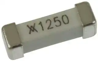
FUSE, SMD, 1.25A, 4113, FAST ACTING
- Manufacturer: LITTELFUSE
- Product type: SMD Fuses
- Fuse Current: 1.25A
- Product Range: FT600 Series
- Fuse Case Style: 4113
- Voltage Rating VAC: 250VAC
- Blow Characteristic: Fast Acting
- Breaking Capacity Current AC: 50A
| Delivery and price | |
|---|---|
| Units per pack | 10000 |
| Price | 0.432 € |
| Current stock | 10+ |
| Lead time | 30 days |
11

## ~~en 5~~ ~~**Surface-mount Fuses** Telecom Fuses Ee ts~~

The telecom FT600 fuse helps telecommunications equipment manufacturers comply with North American overcurrent protection requirements, including Telcordia GR-1089, TIA-968-A (formerly FCC Part 68), and UL60950 3rd edition.

TE Circuit Protection’s telecom fuses offer low temperature-rise performance under sneak current fault events to help prevent damage to circuit traces or multilayer boards, and their low profile and small footprint make them suitable for high-density and space-constrained applications.

## eee, **Benefits** ~~Ee~~ **Features**

- High density placement in multi-port system designs

- Improved temperature rise performance over other similar surface-mount fuse devices under sneak current testing

- The FT600, in conjunction with a thyristor surge suppression device, assists designers to meet regulatory standards without additional series components

- Lead free materials and RoHS compliant

- Halogen free (refers to: Br < 900ppm, Cl < 900ppm, Br+Cl < 1500ppm)

- Low profile and small footprint

- The lightning robust surface-mount fuse offers overcurrent protection in case of power fault events

- Enables the design of equipment complying with applicable telecom specifications including UL60950, TIA-968-A, and Telcordia GR-1089

- Low resistance

## **Applications**

- ADSL, ADSL2, ADSL2plus, SHDSL, VDSL linecards and modems

- T1/E1 systems

- Twisted-pair telecom ports requiring Telcordia GR-1089, UL60950 and FCC Part TIA-968-A compliance

**103**

11

## =» ~~|~~ **Protection Application Guide for Telecommunications and Networking Devices**

To use this guide, follow the steps below:

1. Select your equipment type from the guide below.

2. Use the Key Device Selection Criteria (time-to-open, surface temperature) to determine best suitability for your application.

3. Use Agency Specification / Selection Guide to select a specific part number for each application based on the agency requirements.

## **Key Device Selection Criteria**

|**Key Device Selection Criteria**||||
|---|---|---|---|
|||**Faster**|**Cooler Surface**|
|**Application**|**Specification**|**Time-To-Open**|**Temperature**|
|**Customer premises equipment, IT equipment**|UL 60950|FT600-0500|FT600-2000|
|Analog modems, V.90 modems,|TIA-968-A|FT600-1250||
|ISDN modems, xDSL modems,||||
|ADSL splitters, phone sets, fax machines,||||
|answering machines, caller ID, internet||||
|appliances, PBX systems, POS terminals, wall plugs||||
|**Access network equipment**|Telcordia GR-1089|FT600-1250|FT600-2000|
|Remote terminals, line repeaters, multiplexers,|TIA-968-A|||
|cross-connects, WAN equipment||||
|**Central office switching equipment**|Telcordia GR-1089|FT600-1250|FT600-2000|
|Analog/POTS linecards, ISDN linecards, xDSL modems,|TIA-968-A|||
|ADSL/VDSL splitters, T1/E1 linecards,||||
|multiplexers, CSU/DSU, servers||||


**Note :** This list is not exhaustive. TE Circuit Protection welcomes our customers’ input for additional application ideas for overcurrent protection of telecom applications.

## ~~|~~ **Agency Specification/Selection Guide for FT600 Devices**

Use the guide below to select FT600 devices appropriate for use in your application. The following pages contain specifications for part numbers recommended below. FT600 devices enable telecommunication equipment to meet the applicable protection requirements of these industry specifications. Refer to individual agency specifications for test procedures and circuit schematics. Users should independently evaluate the suitability of, and test each product for their application.

|**Family**|**Product**|**Lightning**|**Power Cross**|
|---|---|---|---|
|FT600|FT600-0500|TIA-968-A – Types A & B|UL60950, 3rd Ed. – 600VAC, 40A|
||FT600-1250|Telcordia GR-1089 – Level 1 and 2|Telcordia GR-1089 – 600 VAC, 40A|
||FT600-2000|TIA-968-A|UL60950|


**Notes:** FT600-1250 and FT600-2000 assist equipment in complying with Telcordia GR-1089 specifications. In-circuit testing is strongly recommended. The FT600-0500, FT600-1250 and FT600-2000 help meet the UL60950 Power Cross and FCC TIA-968-A 68 lightning surge requirements. Note that Type A tests allow for an overcurrent protection component to fuse open during the surge.

|l|l|The FT600-0500, FT600-1250 and FT600-2000 help meet the UL60950 Power Cross and FCC TIA-968-A 68 lightning surge requirements. Note that Type A tests allow for an<br>overcurrent protection component to fuse open during the surge.<br>**Table FT1**<br>**Interrupt Voltage and Current Ratings for FT600 Devices**<br> ~~ne~~|The FT600-0500, FT600-1250 and FT600-2000 help meet the UL60950 Power Cross and FCC TIA-968-A 68 lightning surge requirements. Note that Type A tests allow for an<br>overcurrent protection component to fuse open during the surge.<br>**Table FT1**<br>**Interrupt Voltage and Current Ratings for FT600 Devices**<br> ~~ne~~|The FT600-0500, FT600-1250 and FT600-2000 help meet the UL60950 Power Cross and FCC TIA-968-A 68 lightning surge requirements. Note that Type A tests allow for an<br>overcurrent protection component to fuse open during the surge.<br>**Table FT1**<br>**Interrupt Voltage and Current Ratings for FT600 Devices**<br> ~~ne~~|
|---|---|---|---|---|
|||**Ampere Rating**|**Voltage Rating**<br>**Typical Resistance**|**Typical I2t**|
|||**Part Number**<br>**(A)**|**(V)**<br>**(**Ω**)**|**(A2s)***|
|||FT600-0500<br>0.50|250<br>0.50|1|
|||FT600-1250<br>1.25|250<br>0.10|16|
|||FT600-2000<br>2.00|250<br>0.05|18|


**Note:** The FT600-xxxx devices carry 100% of rated current for 4 hours minimum and 250% of rated current for 1 second minimum, 120 seconds maximum. Resistance measured at 10% of rated current.

*I[2] t is calculated at 10 ms or less.

## ~~A~~ **Figure FT1 Thermal Derating Curve (Normalized) for FT600 Devices**

**==> picture [221 x 133] intentionally omitted <==**

**----- Start of picture text -----**<br>
130<br>120<br>110<br>100<br>pp<br>90<br>80<br>70 HEE EEE<br>-70 -50 -30 -10 10 30 50 70 90 110 130<br>Ambient Temperature ˚C<br>% of Current Rating<br>**----- End of picture text -----**<br>


**104**

RoHS Compliant, ELV Compliant C] **HF** Halogen Free

11

## **Table FT2 Dimensions for FT600 Devices in Millimeters (Inches)** me

|FT600-0500<br>FT600-1250<br>FT600-2000<br>**Part Number**|—<br>—<br>—<br>**Min.**|**A**|10.2<br>(0.402)<br>10.2<br>(0.402)<br>10.2<br>**Max.**|—<br>—<br>—<br>**Min.**|**B**|3.1<br>(0.122)<br>3.1<br>(0.122)<br>3.1<br>**Max.**|—<br>—<br>—<br>**Min.**|**C**|3.1<br>(0.122)<br>3.1<br>(0.122)<br>3.1<br>**Max.**|FT2<br>FT2<br>FT2<br>**Figure**|
|---|---|---|---|---|---|---|---|---|---|---|


(0.402) (0.122) (0.122)

~~a~~ **Figure FT2 Dimension Figures for FT600 Devices**

A C ——— ~~—~~ F ~~S~~ B ~~ty~~ L ~~d4~~

## **Figure FT3 Typical Time-to-open Characteristics (at 20°C) for FT600 Devices** ~~A~~

**==> picture [484 x 315] intentionally omitted <==**

**----- Start of picture text -----**<br>
FT600 A = FT600-0500 | Figure FT3<br>B = FT600-1250 0.500A 1.25A 2A<br>100<br>C = FT600-2000<br>a a aee<br>A B C<br>10 A<br>ekees eee e eee eeee eeee<br>ee<br>1 aNd<br>eeeS<br>SS<br>EN ETN TTT<br>Lt [TTT] ttt<br>0.1<br>EEA<br>a aA<br>ee eee<br>0.01<br>dN LA<br>aeee ee NS ee<br>a |<br>0.001 a NN<br>0.1 1 10 100 1000<br>Current in Amperes<br>Time (sec)<br>**----- End of picture text -----**<br>


**105**

RoHS Compliant, ELV Compliant C] **HF** Halogen Free

**Table FT3 Physical Characteristics and Environmental Specifications for FT600 Devices** mm

11

## **Physical Characteristics**

|Terminal material|Silver-plated brass*|
|---|---|
|Body material|Ceramic|
|Termination solderability|Per IEC-60127-4|


*FT600 devices use high Pb content solder for internal construction. They are RoHS compliant.

## **Environmental Specifications**

**Test Conditions** Solder heat withstand Per MIL-STD-202, Method 210, Test Condition J Solvent resistance Per MIL-STD-202F, Method 215J Storage temperature 30°C/ 85% RH Storage humidity Per MIL-STD-202F, Method 106F

## **Table FT4 Packaging and Marking Information for FT600 Devices** Mm

||**Bag**|**Tape & Reel**|**Standard Package**|||
|---|---|---|---|---|---|
|**Part Number**|**Quantity**|**Quantity**|**Quantity**|**Part Marking**|**Agency Recognition**|
|FT600-0500-2|—|2,500|10,000|500|UL, CSA|
|FT600-1250-2|—|2,500|10,000|1250|UL, CSA|
|FT600-2000-2|—|2,500|10,000|2000|UL, CSA|


**Note:** The -2 designates tape and reel, the package style for this product.

## **Table FT5 Recommended Pad Layouts for FT600 Devices in Millimeters (Inches) Nominal** mm

po **Figure FT4 Device A B C D Figure for Dimensions** FT600-0500 12.6 4.0 3.7 5.2 FT4 D C (0.496) (0.157) (0.145) (0.204) ~~ee rr~~ FT600-1250 12.6 4.0 3.7 5.2 FT4 B ~~ee~~ (0.496) (0.157) (0.145) (0.204) LI U ~~l.—t~~ FT600-2000 12.6 4.0 3.7 5.2 FT4 (0.496) (0.157) (0.145) (0.204) A ~~oo~~ /}—— — ~~—~~

## —~EK&i—>=~—>=——>——*—{;<COES=x&4W—aq—E——E **Solder Reflow and Rework Recommendations for FT600 Devices**

## **Solder Reflow**

- Recommended reflow methods: IR, vapor phase oven, hot air oven

- Devices can be cleaned using standard industry methods and solvents

## **Rework**

- If a device is removed from the board, it should be discarded and replaced by a new device

**==> picture [180 x 129] intentionally omitted <==**

**----- Start of picture text -----**<br>
po Figure FT5<br>Preheating Soldering Cooling<br>300<br>250<br>200<br>150<br>100<br>50<br>0<br>30-90 120<br>10 to 20<br>Time (s)<br>Temperature (˚C)<br>**----- End of picture text -----**<br>


**106**

RoHS Compliant, ELV Compliant CO **HF** Halogen Free

11

## ~~Me~~ **Table FT6 Tape and Reel Specifications for FT600 Devices**

|**Dimension**<br>**Description**<br>Carrier tape width<br>Sprocket hole pitch<br>Sprocket hole diameter<br>Tape thickness<br>**Reel Dimensions**<br>Reel diameter|**EIA Mark**<br>W<br>P0<br>P1<br>P2<br>A0<br>B0<br>D0<br>F<br>E1<br>T max.<br>K0<br>A max.|**Dimension (mm)**<br>24<br>4<br>8<br>2<br>3.68<br>10.44<br>1.5<br>11.5<br>1.75<br>0.3<br>3.25<br>331.5|**Tolerance**<br>±0.3<br>±0.1<br>±0.1<br>±0.1<br>±0.1<br>±0.1<br>+0.1 / -0.0<br>±0.1<br>±0.1<br>±0.05<br>+1.0 / -0.05|
|---|---|---|---|
|Core diameter|N min.|98.5||
|Space between flanges less devices|W0|25|±0.5|
|Reel width|W1max.|31||


**==> picture [515 x 163] intentionally omitted <==**

**----- Start of picture text -----**<br>
a| Figure FT6 EIA Referenced Taped Component Dimensions for FT600 Devices<br>P0  [Note 1]<br>T P2  [Note 6] A E1<br>Notes:<br>T o D0 S reste xs 4 1. 10 sprocket hole pitch cumulative tolerance ±0.2<br>F [Note 6] 2. Allowable camber to be 1mm/250mm<br>W 3. Material: Black conductive<br>B0 4. Abottom of the pocket0 and B0 measured on a plane 0.3mm above the<br>5. K0 measured from the plane on the inside bottom<br>of the pocket to the top surface of the carrier<br>Lae aoe 6. Pocket position relative to sprocket hole measured<br>as true position of pocket, not pocket hole<br>K0 P1 A0 7. Quantity per reel to be 174m<br>al — 7 — A<br>**----- End of picture text -----**<br>


**==> picture [515 x 157] intentionally omitted <==**

**----- Start of picture text -----**<br>
a| Figure FT7 EIA Referenced Reel Dimensions for FT600 Devices<br>W1<br>W0<br>as 45<br>ø13.2±0.2<br>(0.52±0.008)<br>120°<br>17.2±0.2<br>A N (0.677±0.008)<br>2.2±0.2<br>(0.087±0.008) Detail A<br>See “Detail A” HD) b<br>**----- End of picture text -----**<br>


**107**

RoHS Compliant, ELV Compliant **HF** Halogen Free

11

## ~~a~~ **Part Numbering System for FT600 Devices**

**FT 600 - 1250 -2**

**==> picture [68 x 87] intentionally omitted <==**

**----- Start of picture text -----**<br>
Packaging<br>-2 = Tape and Reel<br>Current in Amperes<br>1250 = 1.25<br>0500 = 0.500<br>2000 = 2.00<br>Voltage Rating<br>Product Family<br>**----- End of picture text -----**<br>


## ~~0~~ **Warning :**

All information, including illustrations, is believed to be accurate and reliable. Users, however, should independently evaluate the suitability of and test each product selected for their application. Tyco Electronics Corporation and/or its Affiliates in the TE Connectivity Ltd. family of companies (“TE”) makes no warranties as to the accuracy or completeness of the information, and disclaims any liability regarding its use.TE’s only obligations are those in the TE Standard Terms and Conditions of Sale for this product, and in no case will TE be liable for any incidental, indirect, or consequential damages arising from the sale, resale, use, or misuse of the product. Specifications are subject to change without notice. In addition,TE reserves the right to make changes to materials or processing that do not affect compliance with any applicable specification without notification to Buyer.

**108**

RoHS Compliant, ELV Compliant CJ **HF** Halogen Free
Updated at February 9, 2023
Founded in 1927 and headquartered in Chicago, Illinois, Littelfuse is a premier global manufacturer of circuit protection, power control, and sensing technologies. Widely recognized for pioneering the first small, fast-acting protective fuse, the company has grown into an industry leader whose highly reliable components are essential to modern industrial, transportation, and consumer electronics applications worldwide. At the core of the Littelfuse portfolio is an expansive and industry-leading range of circuit protection solutions. This encompasses a massive selection of traditional fuses, fuse holders, and resettable PTC thermistor fuses designed to safely interrupt overcurrent conditions. To defend against electrical overstress, Littelfuse also provides advanced transient voltage suppression (TVS) technologies, including thousands of specialized TVS diodes, TVS varistors, and gas discharge tubes (GDTs) that ensure robust defense against voltage spikes and environmental hazards. Beyond its foundational protection components, Littelfuse manufactures a diverse array of discrete semiconductors, sensors, and switching devices. Engineers rely on their high-performance thyristors, including TRIACs and SCRs, alongside power-efficient Schottky diodes and MOSFETs for demanding power control applications. Complemented by precision proximity sensors and highly reliable reed and solid-state relays, Littelfuse delivers the critical building blocks required for secure, efficient, and complete system design.
About Novapart
Novapart is a B2B electronic component broker specialising in stock shortages and cost reduction. We source hard-to-find parts and identify compliant alternatives across a catalogue of 410,000+ components from 500+ manufacturers.
Learn more →Stock Shortage Specialist
When a component is unavailable, discontinued or has an unacceptable lead time, we tap into our network of vetted European and Asian distributors to source what you need — without compromising on quality or traceability.
Request a quote →Compliant Alternatives
We identify pin-to-pin, electrically equivalent substitutes that meet the same certifications (RoHS, AEC-Q100, REACH) as your original specification — validated against datasheets, not just part numbers. Often at a lower cost.
BOM Analysis service →