


FS380R12A6T4BBPSA1
IGBT Module, Six Pack, 250 A, 1.6 V, 870 W, 150 °C, Module
- Manufacturer: INFINEON
- Product type: IGBT Modules
- SVHC: No SVHC (25-Jun-2025)
- Product Range: HybridPACK Series
- IGBT Technology: IGBT4 - T4
- IGBT Termination: Press Fit
- Power Dissipation: 870W
- IGBT Configuration: Six Pack
- Transistor Mounting: Panel
- DC Collector Current: 250A
- Power Dissipation Pd: 870W
- Transistor Case Style: Module
- Operating Temperature Max: 150°C
- Junction Temperature Tj Max: 150°C
- Continuous Collector Current: 250A
- Collector Emitter Voltage Max: 1.2kV
- Collector Emitter Voltage V(br)ceo: 1.2kV
- Collector Emitter Saturation Voltage: 1.6V
- Collector Emitter Saturation Voltage Vce(on): 1.6V
| Delivery and price | |
|---|---|
| Units per pack | 1 |
| Price | 598.54 € |
| Current stock | 10+ |
| Lead time | 30 days |
# FS380R12A6T4B
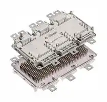
HybridPACK™ **FS380R12A6T4B** Drive Module
**==> picture [213 x 125] intentionally omitted <==**
**----- Start of picture text -----**<br>
T<br>T<br>T<br>Ae NE KE<br>VCES = 1200 V<br>IC = 380 A<br>**----- End of picture text -----**<br>
## Typical Applications
- •Automotive Applications
- •Hybrid Electrical Vehicles (H)EV
- •Motor Drives
- •Commercial Agriculture Vehicles
## Description
The HybridPACK[TM] Drive is a very compact six-pack module (1200V/380A) optimized for hybrid and electric vehicles. The power module implements the IGBT4 generation. The chipset has high short circuit ruggedness and come with a matching efficient and soft switching Emcon4 diode.
## Electrical Features
- •Blocking voltage 1200V
- •Low VCEsat
- •Low Switching Losses
- •Low Qg and Crss
- •Low Inductive Design
- •Tvj op = 150°C
## Mechanical Features
- •4.2kV DC 1sec Insulation
- •High Creepage and Clearance Distances
- •High Power Density
The new HybridPACK[TM] Drive power module family comes with mechanical guiding elements supporting easy assembly processes for customers. Furthermore, the press-fit pins for the signal terminals avoid additional time consuming selective solder processes, which provides cost savings on system level and increases system reliability. The direct cooled baseplate with PinFin structure and optimized ceramic material in the FS380R12A6T4B product best utilizes the implemented chipset and shows superior thermal characteristics. Due to the high clearance & creepage distances, the module well suited for increased system working voltages and supports modular inverter approaches.
- •High Performance Si3N4 Ceramic
- •Direct Cooled PinFin Base Plate
- •Guiding elements for PCB and cooler assembly
- •Integrated NTC temperature sensor
- •PressFIT Contact Technology
- •RoHS compliant
- •UL 94 V0 module frame
|Product Name|OrderingCode|
|---|---|
|FS380R12A6T4B|SP001632438|
Final Data Sheet
2
FS380R12A6T4B HybridPACK™ Drive Module
**==> picture [146 x 64] intentionally omitted <==**
## 2 IGBT,Inverter
## 2.1 Maximum Rated Values
|2 IGBT,Inverter<br>2.1 Maximum Rated Values|||||||
|---|---|---|---|---|---|---|
|Parameter|Conditions|Symbol||Value||Unit|
|Collector-emitter voltage|Tvj= 25°C|VCES||12001)||V|
|Implemented collector current||ICN||380||A|
|Continuous DC collector current|TF= 100°C, Tvj max= 175°C|IC nom||2502)||A|
|Repetitive peak collector current|tP= 1 ms|ICRM||760||A|
|Total power dissipation|TF= 75°C, Tvj max= 175°C|Ptot||8702)||W|
|Gate-emitter peak voltage||VGES||+/-20||V|
|2.2 Characteristic Values|||min.|typ.|max.||
|Collector-emitter saturation voltage|IC= 250 A, VGE= 15 V<br>IC= 250 A, VGE= 15 V<br>IC= 250 A, VGE= 15 V<br>IC= 380 A, VGE= 15 V Tvj= 25°C<br>IC= 380 A, VGE= 15 V Tvj= 150°C<br>Tvj= 25°C<br>Tvj= 125°C<br>Tvj= 150°C|VCE sat||1.60<br>1.85<br>1.90<br>1,95<br>2,40|1.95|V|
|Gate threshold voltage|IC= 9.75 mA, VCE= VGE<br>Tvj= 25°C|VGEth|5.20|5.80|6.40|V|
|Gate charge|VGE= -8 V ... 15 V, VCE= 600V|QG||1.75||µC|
|Internal gate resistor|Tvj= 25°C|RGint||2.5||Ω|
|Input capacitance|f = 1 MHz, VCE= 25 V, VGE= 0 V<br>Tvj= 25°C|Cies||19.0||nF|
|Reverse transfer capacitance|f = 1 MHz, VCE= 25 V, VGE= 0 V<br>Tvj= 25°C|Cres||0.81||nF|
|Collector-emitter cut-off current|VCE= 1200 V, VGE= 0 V<br>Tvj= 25°C|ICES|||1.0|mA|
|Gate-emitter leakage current|VCE= 0 V, VGE= 20 V<br>Tvj= 25°C|IGES|||400|nA|
|Turn-on delay time, inductive load|IC= 250 A, VCE= 600 V<br>VGE= -8 / +15 V<br>RGon= 2.2Ω<br>Tvj= 25°C<br>Tvj= 125°C<br>Tvj= 150°C|td on||0.13<br>0.14<br>0.14||µs|
|Rise time, inductive load|IC= 250 A, VCE= 600 V<br>VGE= -8 / +15 V<br>RGon= 2.2Ω<br>Tvj= 25°C<br>Tvj= 125°C<br>Tvj= 150°C|tr||0.05<br>0.05<br>0.05||µs|
|Turn-off delay time, inductive load|IC= 250 A, VCE= 600 V<br>VGE= -8 / +15 V<br>RGoff= 2.2Ω<br>Tvj= 25°C<br>Tvj= 125°C<br>Tvj= 150°C|td off||0.47<br>0.57<br>0.60||µs|
|Fall time, inductive load|IC= 250 A, VCE= 600 V<br>VGE= -8 / +15 V<br>RGoff= 2.2Ω<br>Tvj= 25°C<br>Tvj= 125°C<br>Tvj= 150°C|tf||0.10<br>0.20<br>0.22||µs|
|Turn-on energy loss per pulse|IC= 250 A, VCE= 600 V, LS= 20 nH<br>VGE= -8 / +15 V<br>RGon= 2.2Ω<br>di/dt (Tvj25°C) = 4000 A/µs<br>di/dt (Tvj150°C) = 3800 A/µs<br>Tvj= 25°C<br>Tvj= 125°C<br>Tvj= 150°C|Eon||19.0<br>26.5<br>29.0||mJ|
|Turn-off energy loss per pulse|IC= 250 A, VCE= 600 V, LS= 20 nH<br>VGE= -8 / +15 V<br>RGoff= 2.2Ω<br>dv/dt (Tvj25°C) = 3300 V/µs<br>dv/dt (Tvj150°C) = 3000 V/µs<br>Tvj= 25°C<br>Tvj= 125°C<br>Tvj= 150°C|Eoff||18.5<br>28.0<br>31.0||mJ|
|SC data|VGE ≤15 V, VCC= 800 V<br>VCEmax= VCES-LsCE·di/dt<br>Tvj= 25°C<br>Tvj= 150°C<br>tP ≤8 µs,<br>tP ≤6 µs,|ISC||1500<br>1200||A|
|Thermal resistance, junction to cooling fluid|per IGBT;∆V/∆t = 10 dm³/min, TF= 75°C|RthJF||0.1003)|0.1153)|K/W|
|Temperature under switching conditions|topcontinuous|Tvj op|-40||150|°C|
> 1) For applications with applied blocking voltage > 60% of the specified maximum collector-emitter voltage, we recommend to evaluate the impact of the cosmic radiation effect in early design phase. For assessment please contact local Infineon sales office.
> 2) Verified by characterization / design not by test.
> 3) Cooler design and flow direction according to application note AN-HPDPERF-ASSEMBLY. Cooling fluid 50% water / 50% ethylenglycol.
V3.1, 2019-09-10
Final Data Sheet
3
FS380R12A6T4B HybridPACK™ Drive Module
**==> picture [146 x 64] intentionally omitted <==**
## 3 Diode, Inverter
## 3.1 Maximum Rated Values
|3 Diode, Inverter<br>3.1 Maximum Rated Values|||||||
|---|---|---|---|---|---|---|
|Parameter|Conditions|Symbol||Value||Unit|
|Repetitive peak reverse voltage|Tvj= 25°C|VRRM||12001)||V|
|Implemented forward current||IFN||380||A|
|Continuous DC forward current||IF||2502)||A|
|Repetitive peak forward current|tP= 1 ms|IFRM||760||A|
|I²t - value|VR= 0 V, tP= 10 ms, Tvj= 125°C<br>VR= 0 V, tP= 10 ms, Tvj= 150°C|I²t||10000<br>8800||A²s<br>A²s|
|3.2 Characteristic Values|||min.|typ.|max.||
|Forward voltage|IF= 250 A, VGE= 0 V<br>IF= 250 A, VGE= 0 V<br>IF= 250 A, VGE= 0 V<br>IF= 380 A, VGE= 0 V Tvj= 25°C<br>IF= 380 A, VGE= 0 V Tvj= 150°C<br>Tvj= 25°C<br>Tvj= 125°C<br>Tvj= 150°C|VF||1.60<br>1.55<br>1.55<br>1,85<br>1,80|2.00|V|
|Peak reverse recovery current|IF= 250 A, - diF/dt = 3800 A/µs (Tvj= 150°C)<br>VR= 600 V<br>VGE= -8 V<br>Tvj= 25°C<br>Tvj= 125°C<br>Tvj= 150°C|IRM||245<br>300<br>315||A|
|Recovered charge|IF= 250 A, - diF/dt = 3800 A/µs (Tvj= 150°C)<br>VR= 600 V<br>VGE= -8 V<br>Tvj= 25°C<br>Tvj= 125°C<br>Tvj= 150°C|Qr||24.0<br>42.5<br>48.0||µC|
|Reverse recovery energy|IF= 250 A, - diF/dt = 3800 A/µs (Tvj= 150°C)<br>VR= 600 V<br>VGE= -8 V<br>Tvj= 25°C<br>Tvj= 125°C<br>Tvj= 150°C|Erec||10.0<br>17.5<br>19.5||mJ|
|Thermal resistance, junction to cooling fluid|per diode;∆V/∆t = 10 dm³/min, TF= 75°C|RthJF||0.1403)|0.1603)|K/W|
|Temperature under switching conditions|topcontinuous|Tvj op|-40||150|°C|
## - 4 NTC Thermistor
||||||||
|---|---|---|---|---|---|---|
|4 NTC-Thermistor|||min.|typ.|max.||
|Parameter|Conditions|Symbol||Value||Unit|
|Rated resistance|TC= 25°C|R25||5.00||kΩ|
|Deviation of R100|TC= 100°C, R100= 493Ω|∆R/R|5||5|%|
|Power dissipation|TC= 25°C|P25|||20.0|mW|
|B-value|R2= R25exp [B25/50(1/T2- 1/(298,15 K))]|B25/50||3375||K|
|B-value|R2= R25exp [B25/80(1/T2- 1/(298,15 K))]|B25/80||3411||K|
|B-value|R2= R25exp [B25/100(1/T2- 1/(298,15 K))]|B25/100||3433||K|
Specification according to the valid application note.
> 1) For applications with applied blocking voltage > 60% of the specified maximum collector-emitter voltage, we recommend to evaluate the impact of the cosmic radiation effect in early design phase. For assessment please contact local Infineon sales office.
> 2) Verified by characterization / design not by test.
3) Cooler design and flow direction according to application note AN-HPDPERF-ASSEMBLY. Cooling fluid 50% water / 50% ethylenglycol.
V3.1, 2019-09-10
Final Data Sheet
4
FS380R12A6T4B HybridPACK™ Drive Module
**==> picture [146 x 64] intentionally omitted <==**
## 5 Module
|5 Module|||||||
|---|---|---|---|---|---|---|
|Parameter|Conditions|Symbol||Value||Unit|
|Isolation test voltage|RMS, f = 0 Hz, t = 1 sec|VISOL||4.2<br>||kV|
|Maximum RMS module terminal current|TF= 75°C, TCt= 105°C|ItRMS||550||A|
|Material of module baseplate||||Cu+Ni1)|||
|Internal isolation|basic insulation (class 1, IEC 61140)|||Si3N4|||
|Creepage distance|terminal to heatsink<br>terminal to terminal|dCreep||9.0<br>9.0||mm|
|Clearance|terminal to heatsink<br>terminal to terminal|dClear||4.5<br>4.5||mm|
|Comperative tracking index||CTI||> 200|||
||||min.|typ.|max.||
|Pressure drop in cooling circuit|∆V/∆t = 10.0 dm³/min; TF= 75°C|∆p||642)||mbar|
|Maximum pressure in cooling circuit|Tbaseplate< 40°C<br>Tbaseplate> 40°C<br>(relative pressure)|p|||2.5<br>2.0|bar|
|Stray inductance module||LsCE||8.0||nH|
|Module lead resistance, terminals - chip|TF= 25 °C, per switch|RCC'+EE'||0.75||mΩ|
|Storage temperature||Tstg|-40||125|°C|
|Mounting torque for modul mounting|Screw M4 baseplate to heatsink|M|1.80|2.00|2.203)|Nm|
|Weight||G||720||g|
1) Ni plated Cu baseplate.
2) Cooler design and flow direction according to application note AN-HPDPERF-ASSEMBLY. Cooling fluid 50% water / 50% ethylenglycol. 3) According to application note AN-HPDPERF-ASSEMBLY. Final Data Sheet 5
V3.1, 2019-09-10
5
FS380R12A6T4B HybridPACK™ Drive Module
## 6 Characteristics Diagrams
output characteristic IGBT,Inverter (typical) IC = f (VCE) VGE = 15 V
output characteristic IGBT,Inverter (typical) IC = f (VCE) Tvj = 150°C
**==> picture [504 x 596] intentionally omitted <==**
**----- Start of picture text -----**<br>
600 600<br>Tvj = 25°C VGE = 19V<br>550 Tvj = 125°C 550 VGE = 17V<br>F Tvj = 150°C j F VGE LL = 15V A |<br>500 500 VGE = 13V<br>ee | VGE = 11V pt ee |<br>VGE = 9V<br>e e<br>450 450<br>s eeeeee | pe| |<br>400 400<br>ee ee ee e ee<br>350 350<br>Se oe ee eee) ae<br>300 i ye 300 7<br>i<br>250 250<br>ee<br>200 200<br>2 ee ee ee<br>150 Ae 150 eee<br>100 100<br>ee ee eeeeeAe ae<br>ee 2A<br>50 50<br>2<br>0 0<br>0,0 0,5 1,0 1,5 2,0 2,5 3,0 3,5 0,0 0,5 1,0 1,5 2,0 2,5 3,0 3,5 4,0 4,5 5,0<br>VCE [V] VCE [V]<br>transfer characteristic IGBT,Inverter (typical) switching losses IGBT,Inverter (typical)<br>IC = f (VGE) Eon = f (IC), Eoff = f (IC),<br>VCE = 20 V VGE = +15 V / -8 V, RGon = 2.2 Ω, RGoff = 2.2 Ω, VCE = 600 V<br>600 180<br>Tvj = 25°C Eon, Tvj = 125°C<br>550 Fe TTvjvj = 125°C = 150°C 160 EEoffon —_ , T, Tvjvj = 125°C = 150°C<br>500 Eoff, Tvj = 150°C<br>eto fH<br>140<br>450<br>ee ) — :<br>400 120<br>350<br>pees) FEE<br>100<br>oe ee<br>300<br>80<br>250<br>Pt | | A 1<br>200 ee 60<br>eea<br>150<br>PA er<br>40<br>100<br>20<br>50 yan et<br>a a ee<br>24 ee<br>0 0<br>5 6 7 8 9 10 11 12 13 0 100 200 300 400 500 600<br>VGE [V] IC [A]<br> [A] [A]<br>IC IC<br> [A]<br>IC E [mJ]<br>**----- End of picture text -----**<br>
V3.1, 2019-09-10
Final Data Sheet
6
FS380R12A6T4B HybridPACK™ Drive Module
switching losses IGBT,Inverter (typical) Eon = f (RG), Eoff = f (RG), VGE = +15V / -8V, IC = 250 A, VCE = 600V
transient thermal impedance IGBT,Inverter ZthJF = f (t), ∆V/∆t = 10 dm³/min; 50% water / 50% ethylenglycol Tf = 75°C; cooler design according to AN-HPDPERF-ASSEMBLY
**==> picture [500 x 273] intentionally omitted <==**
**----- Start of picture text -----**<br>
120 1<br>Eon, Tvj = 125°C ZthJF : IGBT<br>110 Eoff, Tvj = 125°C<br>Eon, Tvj = 150°C<br>100 Eoff, Tvj = 150°C<br>90 S ee eee E E<br>80 O e 0,1<br>70<br>+--+ Ee<br>60<br>50<br>CCA Ene<br>40 4ee 0,01 i<br>30<br>A)<br>20<br>i: 1 2 3 4<br>ri[K/W]: 0,007 0,038 0,05 0,02<br>10 FEEEEEEEE τ i[s]: 0,001 0,03 0,25 1,5<br>0 Pitt tt ett tyEE) 0,001 EEE Eer RR EE Seto<br>0 2 4 6 8 10 12 14 16 18 20 22 0,001 0,01 0,1 1 10<br>RG [ Ω ] t [s]<br> [K/W]<br>E [mJ] thJF<br>Z<br>**----- End of picture text -----**<br>
reverse bias safe operating area IGBT,Inverter (RBSOA) IC = f (VCE); VGE = +15V / -8V, RGoff = 2.2 Ω, Tvj = 150°C
thermal impedance IGBT,Inverter RthJF = f (∆V/∆t), Tf = 75°C; 50% water / 50% ethylenglycol cooler design according to AN-HPDPERF-ASSEMBLY
**==> picture [500 x 273] intentionally omitted <==**
**----- Start of picture text -----**<br>
800 ee 0,129 a RthJF: IGBT<br>ee 0,127 ee<br>700<br>0,125<br>Teer] A EE<br>600<br>0,123<br>pa PXELEE Eee<br>500<br>0,121<br>pp TINSEL<br>400 0,119<br>ee 0,117 EEN EE<br>300<br>0,115<br>PPE) eee Nee<br>200<br>| 0,113 EEE RSStEE<br>IC, Modul<br>100 e IC n , Chip t mm<br>0,111<br>tt} Poppe ss<br>T T.<br>0 | ty } 0,109 EEE<br>0 200 400 600 800 1000 1200 1400 4 5 6 7 8 9 10 11 12 13 14<br>VCE [V] ∆ V/ ∆ t [dm³/min]<br> [A] [K/W]<br>IC<br>thJF<br>R<br>**----- End of picture text -----**<br>
V3.1, 2019-09-10
Final Data Sheet
7
FS380R12A6T4B HybridPACK™ Drive Module
forward characteristic of Diode, Inverter (typical) IF = f (VF)
switching losses Diode, Inverter (typical) Erec = f (IF),
RGon = 2.2 Ω, VCE = 600 V
**==> picture [502 x 273] intentionally omitted <==**
**----- Start of picture text -----**<br>
600 30,0<br>Tvj = 25°C Erec, Tvj = 125°C<br>550 E Tvj = 125°C LLIS 27,0 Erec — , Tvj = 150°C<br>Tvj = 150°C<br>500<br>eA, eA<br>24,0<br>450<br>S e ep EE ee<br>21,0<br>400<br>TCE yy a<br>350 eeee 18,0 eee<br>300 15,0<br>250 FECES Ege<br>12,0<br>200<br>a oyae<br>9,0<br>150<br>Sceeéce EET<br>6,0<br>100 AA<br>3,0<br>50 n/a<br>2 2 eee<br>0 0,0<br>0,0 0,3 0,6 0,9 1,2 1,5 1,8 2,1 2,4 0 100 200 300 400 500 600<br>VF [V] IF [A]<br> [A]<br>IF E [mJ]<br>**----- End of picture text -----**<br>
switching losses Diode, Inverter (typical) Erec = f (RG), IF = 250 A, VCE = 600 V
transient thermal impedance Diode, Inverter ZthJF = f (t), ∆V/∆t = 10 dm³/min; 50% water / 50% ethylenglycol Tf = 75°C; cooler design according to AN-HPDPERF-ASSEMBLY
**==> picture [500 x 273] intentionally omitted <==**
**----- Start of picture text -----**<br>
24 1<br>Erec, Tvj = 125°C ZthJC : Diode<br>22 Erec, Tvj = 150°C<br>20 Pt | EE ee Cr e<br>O e<br>18<br>16 0,1<br>PXAP ETP) LUI rer<br>14<br>12<br>10 CCC SSKEEEE PPM Ce Cn<br>8 ee 0,01 2 |<br>6<br>4<br>i: 1 2 3 4<br>ri[K/W]: 0,015 0,07 0,055 0,02<br>2 τ i[s]: 0,001 0,03 0,25 1,5<br>REE Se<br>0 PET EE ET Ty 0,001 LL EE oo l<br>0 2 4 6 8 10 12 14 16 18 20 22 0,001 0,01 0,1 1 10<br>RG [ Ω ] t [s]<br> [K/W]<br>E [mJ]<br>thJC<br>Z<br>**----- End of picture text -----**<br>
V3.1, 2019-09-10
Final Data Sheet
8
FS380R12A6T4B HybridPACK™ Drive Module
thermal impedance Diode, Inverter RthJF = f (∆V/∆t), Tf = 75°C; 50% water / 50% ethylenglycol cooler design according to AN-HPDPERF-ASSEMBLY
NTC-Thermistor-temperature characteristic (typical) R = f (T)
**==> picture [508 x 273] intentionally omitted <==**
**----- Start of picture text -----**<br>
0,174 100000<br>RthJF: Diode Rtyp<br>0,172<br>a ee ee ee<br>Tit Se.<br>0,170<br>: a Ne ee ee<br>0,168 10000<br>PKU TT ETT TE} EEX EET EL<br>0,166<br>a NN ee ee ee<br>0,164 \ fF {| | | At | | | [|<br>PT FEE SEEE<br>0,162 1000<br>PLLINT TET} EEEEEXY TTT<br>0,160<br>HPN]™ HESa ee e SSSCEe NN ee<br>0,158<br>0,156 Pitty TLL CN 100 |ELLE{| | | | [ TLR[| | [AL |<br>4 5 6 7 8 9 10 11 12 13 14 -40 -20 0 20 40 60 80 100 120 140 160<br>∆ V/ ∆ t [dm³/min] TC [°C]<br>] Ω<br> [K/W]<br>R[<br>thJF<br>R<br>**----- End of picture text -----**<br>
pressure drop in cooling circuit ∆p = f (∆V/∆t), Tf = 75°C; 50% water / 50% ethylenglycol cooler design according to AN-HPDPERF-ASSEMBLY
**==> picture [244 x 273] intentionally omitted <==**
**----- Start of picture text -----**<br>
120<br>∆ p: Modul<br>E=SLLLLLIA<br>PT TL<br>100<br>PPE EEL<br>80<br>PCE AA<br>HEE<br>EEE E E EEALE<br>60<br>San 4<br>TEDL EE<br>40<br>PEELE<br>20 COKE EEE<br>PLE ELL<br>THEE ee<br>0<br>4 5 6 7 8 9 10 11 12 13 14<br>∆ V/ ∆ t [dm³/min]<br>p [mbar]<br>∆<br>**----- End of picture text -----**<br>
V3.1, 2019-09-10
Final Data Sheet
9
FS380R12A6T4B HybridPACK™ Drive Module
**==> picture [146 x 64] intentionally omitted <==**
## 7 Circuit diagram
**==> picture [461 x 216] intentionally omitted <==**
**----- Start of picture text -----**<br>
P1 P2 P3<br>T1<br>C1 C3 C5<br>T<br>T2<br>G1 G3 G5<br>E1 E3 E5 T3<br>U V W T<br>C2 C4 C6<br>T4<br>G2 G4 G6 T5<br>E2 E4 E6 T<br>T6<br>N1 N2 N3<br>**----- End of picture text -----**<br>
V3.1, 2019-09-10
Final Data Sheet
10
FS380R12A6T4B HybridPACK™ Drive Module
**==> picture [146 x 64] intentionally omitted <==**
## 8 Package outlines
**==> picture [510 x 588] intentionally omitted <==**
**----- Start of picture text -----**<br>
Ø5,3±0,15 {<br>B<br>n 0,6 F G<br>j A<br>Ø1,2 D E<br>F G 6x(N1-N3;P1-P3)<br>6x D 14±0,26x 6x n 5,5±0,1<br>1±0,15 22,25±0,4 16±0,2 6x<br>16,25 n 0,5 D E<br>j A<br>9,75±0,4 Y Ø1,6 B C<br>B 5±0,4 N1 P1 N2 P2 N3 P3 8x<br>0 0 X 0<br>15,5±0,5<br>C2 E2 G2 C4 E4 G4 C6 E6 G6<br>4±0,3<br>T1 T3 T5<br>6,35±0,5 T2 T4 T6<br>66,5±0,5 G1 E1 C1 G3 E3 C3 G5 E5 C5<br>A<br>82 82<br>C 90,75±0,487±0,4 U V W C<br>1±0,15<br>3x 98,25<br>104,25±0,4 E 3x n 5,5±0,1<br>H 14±0,23x n 0,6 H I<br>j A<br>Ø1,2 D E<br>I 3x(U;V;W)<br>B<br>S<br>X-Y ( 1 : 1 )<br>9,3±0,28x LD1 Y N1 P1 D2 N2 P2 D3 N3 P3 D4 j 8x n 0,8 A L M<br>0 Ø1,6 B C<br>c 0,3 CZ A 8 M<br>6x common zones: X<br>D2-D3D1-D2 dimensioned for 18,85 C2 E2 G2 C4 E4 G4 C6 E6 G6<br>D3-D4D8-D7 EJOT Delta PTWN5451 30 x J Z K [origin axis generated by ] C2;E2;G2;C4;E4;G4;C6;E6;G6<br>D7-D6D6-D5 R<br>T<br>51,85 T1 T3 T5<br>59,35 T2 T4 T6<br>67,15 G1 E1 C1 G3 E3 C3 G5 E5 D5<br>69,85 C5<br>3,94±0,5 74,1<br>refers 82<br>to local CZ D8 U V W C<br>D7 D6<br>Area R;S or T<br>(19,75)<br>Z ( 1,5 : 1 )<br>Drawing: D00138581_04<br>edges gen. tolerances surface<br>DIN ISO 13715 2. DIN ISO167421. DIN-TG4 DIN EN ISO1302 j **** A KB CJ<br>2768-mK 24x<br>All dimensions refer to module in C2 E2 G2 ** Pin positions checked<br>delivery condition with pin gauge<br>according to Application<br>Note AN-HPD-ASSEMBLY<br>(119,553)<br>(43,305°)<br>8x<br>26±0,3 10,1±0,4 7,6±0,4 06 0-0,2 26,25±0,4 25±0,4 20 5,7 0 13,3 27,33 41,3 60,3 74,67 88,3 107,3 122 127±0,4 128,25±0,4<br>8,5±0,3<br>8x<br>4,5±0,15<br>n<br>4,3±0,15<br>3x 16±0,2<br>reference plane 22.000 7,6±0,4 0 20 0 8,3 27,33 55,3 74,67 87 102,3 122<br>23,25 12,2 0 4 8,05 27,35 34,8 51 55,05 74,65 81,8 98 102,05 125,25<br>12,8±0,2 0<br>23,25 10,25 6,2 0 21,95 23,35 27,35 36,75 40,8 68,95 70,35 74,65 83,75 87 87,8 115,95 117,35 125,25<br>**----- End of picture text -----**<br>
V3.1, 2019-09-10
Final Data Sheet
11
FS380R12A6T4B HybridPACK™ Drive Module
## 9 Label Codes
## 9.1 Module Code
|9 Label Codes<br>9.1 Module Code||||
|---|---|---|---|
|Code Format|Data Matrix|||
|Encoding|ASCII Text|||
|Symbol Size|16x16|||
|Standard|IEC24720 and IEC16022|||
|Code Content|Content<br>Module Serial Number<br>Module Material Number<br>Production Order Number<br>Datecode (Production Year)<br>Datecode (Production Week)|Digit<br>1 - 5<br>6 - 11<br>12 - 19<br>20 - 21<br>22 - 23|Example (below)<br>71549<br>142846<br>55054991<br>15<br>30|
|Example|71549142846550549911530|||
## 9.2 Packing Code
|9.2 Packing Code|||||
|---|---|---|---|---|
|9.2 Packing Code<br>Code Format|Code128||||
|Encoding|Code Set A||||
|Symbol Size|34 digits||||
|Standard|IEC8859-1||||
|Code Content|Content<br>Backend Construction Number<br>Production Lot Number<br>Serial Number<br>Date Code<br>Box Quantity<br>~~Sn~~|Identifier<br>X<br>1T<br>S<br>9D<br>Q<br>~~Sn~~|Digit<br>2 - 9<br>12 - 19<br>21 - 25<br>28 - 31<br>33 - 34<br>~~Sn~~|Example (below)<br>95056609<br>2X0003E0<br>754389<br>1139<br>15<br>~~Sn~~|
|Example|X950566091T2X0003E0S754389D1139Q15<br>~~Sn~~||||
V3.1, 2019-09-10
Final Data Sheet
12
FS380R12A6T4B HybridPACK™ Drive Module
**==> picture [146 x 64] intentionally omitted <==**
## Revision History
Major changes since previous revision
|Revision History|Revision History||
|---|---|---|
|Reference|Date|Description|
|V1.0|2017-05-11|Target datasheet|
|V2.0|2018-08-27|Preliminary datasheet|
|V3.0|2019-05-09|Final datasheet|
|V3.1|2019-09-10|Correction of product weight and document cross references|
V3.1, 2019-09-10
Final Data Sheet
13
FS380R12A6T4B HybridPACK™ Drive Module
**==> picture [146 x 64] intentionally omitted <==**
## Terms & Conditions of usage
Edition 2018-08-01
Published by Infineon Technologies AG 81726 Munich, Germany © 2018 Infineon Technologies AG All Rights Reserved.
## Legal Disclaimer
The information given in this document shall in no event be regarded as a guarantee of conditions or characteristics. With respect to any examples or hints given herein, any typical values stated herein and/or any information regarding the application of the device, Infineon Technologies hereby disclaims any and all warranties and liabilities of any kind, including without limitation, warranties of non-infringement of intellectual property rights of any third party.
## Information
For further information on technology, delivery terms and conditions and prices, please contact the nearest Infineon Technologies Office (http://www.infineon.com)
## Warnings
Due to technical requirements, components may contain dangerous substances. For information on the types in question, please contact the nearest Infineon Technologies Office.
These components are not designed for “special applications” that demand extremely high reliability or safety such as aerospace, defense or life support devices or systems (Class III medical devices). If you intend to use the components in any of these special applications, please contact your local representative at International Rectifier HiRel Products, Inc. or the Infineon support (https://www.infineon.com/support) to review product requirements and reliability testing.
Infineon Technologies components may be used in special applications only with the express written approval of Infineon Technologies. Class III medical devices are intended to be implanted in the human body or to support and/or maintain and sustain and/or protect human life. If they fail, it is reasonable to assume that the health of the user or other persons may be endangered.
## Trademarks
## Trademarks of Infineon Technologies AG
AURIX™, C166™, CanPAK™, CIPOS™, CIPURSE™, EconoPACK™, CoolMOS™, CoolSET™, CORECONTROL™, CROSSAVE™, DAVE™, DI-POL™, EasyPIM™, EconoBRIDGE™, EconoDUAL™, EconoPIM™, EconoPACK™, EiceDRIVER™, eupec™, FCOS™, HITFET™, HybridPACK™, I²RF™, ISOFACE™, IsoPACK™, MIPAQ™, ModSTACK™, my-d™, NovalithIC™, OptiMOS™, ORIGA™, POWERCODE™, PRIMARION™, PrimePACK™, PrimeSTACK™, PRO-SIL™, PROFET™, RASIC™, ReverSave™, SatRIC™, SIEGET™, SINDRION™, SIPMOS™, SmartLEWIS™, SOLID FLASH™, TEMPFET™, thinQ!™, TRENCHSTOP™, TriCore™.
## Other Trademarks
Advance Design System™ (ADS) of Agilent Technologies, AMBA™, ARM™, MULTI-ICE™, KEIL™, PRIMECELL™, REALVIEW™, THUMB™, µVision™ of ARM Limited, UK. AUTOSAR™ is licensed by AUTOSAR development partnership. Bluetooth™ of Bluetooth SIG Inc. CAT-iq™ of DECT Forum. COLOSSUS™, FirstGPS™ of Trimble Navigation Ltd. EMV™ of EMVCo, LLC (Visa Holdings Inc.). EPCOS™ of Epcos AG. FLEXGO™ of Microsoft Corporation. FlexRay™ is licensed by FlexRay Consortium. HYPERTERMINAL™ of Hilgraeve Incorporated. IEC™ of Commission Electrotechnique Internationale. IrDA™ of Infrared Data Association Corporation. ISO™ of INTERNATIONAL ORGANIZATION FOR STANDARDIZATION. MATLAB™ of MathWorks, Inc. MAXIM™ of Maxim Integrated Products, Inc. MICROTEC™, NUCLEUS™ of Mentor Graphics Corporation. MIPI™ of MIPI Alliance, Inc. MIPS™ of MIPS Technologies, Inc., USA. muRata™ of MURATA MANUFACTURING CO., MICROWAVE OFFICE™ (MWO) of Applied Wave Research Inc., OmniVision™ of OmniVision Technologies, Inc. Openwave™ Openwave Systems Inc. RED HAT™ Red Hat, Inc. RFMD™ RF Micro Devices, Inc. SIRIUS™ of Sirius Satellite Radio Inc. SOLARIS™ of Sun Microsystems, Inc. SPANSION™ of Spansion LLC Ltd. Symbian™ of Symbian Software Limited. TAIYO YUDEN™ of Taiyo Yuden Co. TEAKLITE™ of CEVA, Inc. TEKTRONIX™ of Tektronix Inc. TOKO™ of TOKO KABUSHIKI KAISHA TA. UNIX™ of X/Open Company Limited. VERILOG™, PALLADIUM™ of Cadence Design Systems, Inc. VLYNQ™ of Texas Instruments Incorporated. VXWORKS™, WIND RIVER™ of WIND RIVER SYSTEMS, INC. ZETEX™ of Diodes Zetex Limited.
Last update 2011-11-11
V3.1, 2019-09-10
Final Data Sheet
14
w w w . i n f i n e o n . c o m
Published by Infineon Technologies AG
Updated at April 28, 2026
Infineon Technologies is a globally recognized leader in semiconductor solutions, renowned for driving innovation in power management, energy efficiency, and modern mobility. With a strong legacy of engineering excellence, the company provides highly reliable components designed to meet the rigorous demands of industrial, automotive, and advanced commercial applications. The core of our Infineon portfolio is centered on their industry-leading discrete semiconductors. We offer an extensive selection of single and dual MOSFETs, alongside a robust range of single IGBTs and advanced IGBT modules. These flagship power transistors are essential for high-efficiency power conversion and motor control, providing engineers with superior thermal performance and minimized switching losses. Beyond advanced field-effect transistors, the selection includes a comprehensive array of diodes and rectifiers, heavily featuring Schottky diodes, as well as fast-recovery and RF/PIN diodes. This power foundation is further supported by bipolar transistors, intelligent power modules, and thyristor SCR modules, delivering the critical building blocks required for complex power system designs. To support broader system integration, the portfolio also encompasses specialized solutions such as solid-state relays, AC/DC LED driver ICs, and Bluetooth communications modules. From high-power industrial rectifiers to wireless connectivity adapters, Infineon equips designers with the precision components needed to build efficient, scalable, and fully connected electronic systems.
About Novapart
Novapart is a B2B electronic component broker specialising in stock shortages and cost reduction. We source hard-to-find parts and identify compliant alternatives across a catalogue of 410,000+ components from 500+ manufacturers.
Learn more →Stock Shortage Specialist
When a component is unavailable, discontinued or has an unacceptable lead time, we tap into our network of vetted European and Asian distributors to source what you need — without compromising on quality or traceability.
Request a quote →Compliant Alternatives
We identify pin-to-pin, electrically equivalent substitutes that meet the same certifications (RoHS, AEC-Q100, REACH) as your original specification — validated against datasheets, not just part numbers. Often at a lower cost.
BOM Analysis service →