


FMR0H473ZFTP18
Supercapacitor, 47000 µF, 5.5 V, Radial Leaded, -20%, +80%, 5 mm, 1000 hours @ 85°C
- Manufacturer: KEMET
- Product type: EDLC - Electric Double Layer Capacitors
- ESR: 200ohm
- SVHC: No SVHC (04-Feb-2026)
- Capacitance: 47000µF
- Voltage(DC): 5.5V
- Lead Spacing: 5mm
- Product Range: FMR Series
- Product Width: 6.5mm
- Qualification: -
- Product Height: 11.5mm
- Product Length: 10.5mm
- Product Diameter: -
- Capacitor Mounting: Through Hole
- Capacitor Terminals: Radial Leaded
- Capacitance Tolerance: -20%, +80%
- Lifetime @ Temperature: 1000 hours @ 85°C
- Capacitor Case / Package: Radial Box - 2 Pin
- Operating Temperature Max: 85°C
- Operating Temperature Min: -40°C
| Delivery and price | |
|---|---|
| Units per pack | 1 |
| Price | 2.78 € |
| Current stock | 10+ |
| Lead time | 30 days |
FM Series
## **Supercapacitors**
## Overview
## Applications
FM Series Supercapacitors, also known as Electric DoubleLayer Capacitors (EDLCs), are intended for high energy storage applications.
Supercapacitors have characteristics ranging from traditional capacitors and batteries. As a result, supercapacitors can be used like a secondary battery when applied in a DC circuit. These devices are best suited for use in low voltage DC hold-up applications such as embedded microprocessor systems with flash memory.
## Benefits
- Rectangular case
- Wide range of temperature from −25°C to +70°C (all types except FMR) and −40°C to +85°C (FMR type)
- Maintenance free
- Maximum operating voltages of 3.5, 3.6, 5.5, and 6.5 VDC
- Highly reliable against liquid leakage
- Lead-free and RoHS compliant
- Leads can be transverse mounted
## Part Number System
|FM|0H|223|Z|F|TP|18|
|---|---|---|---|---|---|---|
|Series|Maximum<br>Operating Voltage|Capacitance Code|Capacitance<br>Tolerance|Environmental|Tape Type|Height<br>(excluding lead)|
|FM<br>FME<br>FMR<br>FMC|0V = 3.5 VDC<br>0H = 5.5 VDC<br>0J = 6.5 VDC|First two digits<br>represent significant<br>figures. Third digit<br>specifies number of<br>zeros to follow µF<br>code.|Z = −20/+80%|F = Lead-free|TP = AMMO<br>-L1 = Transverse<br>mounting<br>Blank = Bulk|18 = 18 mm<br>Blank = Bulk|
S6012_FM (2026-03-19)
1 | YAGEOGroup.com
**Supercapacitors** FM Series
## Dimensions – Millimeters
**==> picture [415 x 217] intentionally omitted <==**
**----- Start of picture text -----**<br>
For L1 lead option<br>B ±0.5 T ±0.5<br>HL ±0.5<br>LL ±1.0<br>D1 ±0.1 D2 ±0.1<br>5 ±0.5<br>A ±0.5<br>0.4 ±0.1<br>5 ±1<br>**----- End of picture text -----**<br>
**==> picture [337 x 281] intentionally omitted <==**
**----- Start of picture text -----**<br>
Part Number A B T D D HL LL<br>1 2<br>FM0H103ZF 11.5 10.5 5.0 0.5 0.4 13 5<br>FM0H223ZF 11.5 10.5 5.0 0.5 0.4 13 5<br>FM0H473ZF 11.5 10.5 5.0 0.5 0.4 13 5<br>FM0H104ZF 11.5 10.5 6.5 0.5 0.4 13 5<br>FM0H224ZF 11.5 10.5 6.5 0.5 0.4 13 5<br>FM0V473ZF 11.5 10.5 5.0 0.5 0.4 13 5<br>FM0V104ZF 11.5 10.5 5.0 0.5 0.4 13 5<br>FM0V224ZF 11.5 10.5 6.5 0.5 0.4 13 5<br>FM0J473ZF 11.5 10.5 6.5 0.5 0.4 13 5<br>FME0H223ZF 11.5 10.5 5.0 0.5 0.4 13 5<br>FME0H473ZF 11.5 10.5 5.0 0.5 0.4 13 5<br>FMR0H473ZF 11.5 10.5 6.5 0.5 0.4 13 5<br>FMR0H104ZF 11.5 10.5 6.5 0.5 0.4 13 5<br>FMR0V104ZF 11.5 10.5 6.5 0.5 0.4 13 5<br>FMR0V334ZF 11.5 10.5 6.5 0.5 0.4 13 5<br>FMR0V474ZF 15.0 14.0 9.0 0.6 0.6 16.7 3.5<br>FMC0H473ZF 11.5 10.5 5.0 0.5 0.4 13 5<br>FMC0H104ZF 11.5 10.5 6.5 0.5 0.4 13 5<br>FMC0H334ZF 15.0 14.0 9.0 0.6 0.6 16.7 3.5<br>**----- End of picture text -----**<br>
## Lead Terminal Forming
_Add “L1” to the end of bulk part number for transverse mounting option_
S6012_FM (2026-03-19)
2 | YAGEOGroup.com
**Supercapacitors** FM Series
## Performance Characteristics
Supercapacitors should not be used for applications such as ripple absorption because of their high internal resistance (several hundred mΩ to a hundred Ω) compared to aluminum electrolytic capacitors. Thus, its main use would be similar to that of secondary battery such as power back-up in DC circuit. The following list shows the characteristics of supercapacitors as compared to aluminum electrolytic capacitors for power back-up and secondary batteries.
**==> picture [542 x 227] intentionally omitted <==**
**----- Start of picture text -----**<br>
Secondary Battery Capacitor<br>NiCd Lithium Ion Aluminum Electrolytic Supercapacitor<br>– – – –<br>Back-up ability<br>Eco-hazard Cd – – –<br>−40 to +85°C<br>Operating Temperature Range −20 to +60°C −20 to +50°C −55 to +105°C<br>(FR, FT, FMR Type)<br>Charge Time Few hours Few hours Few seconds Few seconds<br>Approximately Approximately<br>Charge/Discharge Life Time Limitless (*1) Limitless (*1)<br>500 times 500 to 1,000 times<br>Restrictions on<br>Yes Yes None None<br>Charge/Discharge<br>Flow Soldering Not applicable Not applicable Applicable Applicable<br>Applicable<br>Automatic Mounting Not applicable Not applicable Applicable<br>(FM and FC series)<br>Leakage, combustion,<br>Safety Risks Leakage, explosion Heat-up, explosion Gas emission (*2)<br>explosion, ignition<br>**----- End of picture text -----**<br>
_(*1) Aluminum electrolytic capacitors and supercapacitors have limited lifetime. However, when used under proper conditions, both can operate within a predetermined lifetime._
_(*2) There is no harm as it is a mere leak of water vapor which transitioned from water contained in the electrolyte (diluted sulfuric acid). However, application of abnormal voltage surge exceeding maximum operating voltage may result in leakage and explosion._
## Typical Applications
**==> picture [542 x 56] intentionally omitted <==**
**----- Start of picture text -----**<br>
Intended Use (Guideline) Power Supply (Guideline) Application Examples of Equipment Series<br>CMOS microcomputer,<br>CMOS microcomputer,<br>Long time back-up 500 μA and below static RAM/DTS FM series<br>IC for clocks<br>(digital tuning system)<br>**----- End of picture text -----**<br>
## Environmental Compliance
All KEMET supercapacitors are RoHS compliant.
**==> picture [72 x 66] intentionally omitted <==**
S6012_FM (2026-03-19)
3 | YAGEOGroup.com
**Supercapacitors** FM Series
## Table 1 – Ratings & Part Number Reference
**==> picture [542 x 272] intentionally omitted <==**
**----- Start of picture text -----**<br>
Maximum Nominal Capacitance Maximum Voltage Holding<br>Maximum ESR<br>Part Number Operating Current at 30 Characteristic Weight (g)<br>Charge Discharge at 1 kHz (Ω)<br>Voltage (VDC) Minutes (mA) Minimum (V)<br>System (F) System (F)<br>FM0V473ZF 3.5 0.047 0.06 200 0.042 - 1.3<br>FMR0V104ZF 3.5 0.10 - 50 0.090 - 1.6<br>FM0V104ZF 3.5 0.10 0.13 100 0.090 - 1.3<br>FM0V224ZF 3.5 0.22 0.30 100 0.20 - 1.6<br>FM0H103ZF 5.5 0.01 0.014 300 0.015 4.2 1.3<br>FME0H223ZF 5.5 0.022 0.028 40 0.033 - 1.3<br>FM0H223ZF 5.5 0.022 0.028 200 0.033 4.2 1.3<br>FME0H473ZF 5.5 0.047 0.06 20 0.071 - 1.3<br>FMC0H473ZF 5.5 0.047 0.06 100 0.071 4.2 1.3<br>FM0H473ZF 5.5 0.047 0.06 200 0.071 4.2 1.3<br>FMR0H473ZF 5.5 0.047 0.062 200 0.071 4.2 1.6<br>FMR0H104ZF 5.5 0.10 - 50 0.15 4.2 1.6<br>FMR0V334ZF 3.6 - 0.33 50 0.3 - 1.6<br>FMR0V474ZF 3.6 - 0.47 25 0.42 - 3.5<br>FMC0H104ZF 5.5 0.10 0.13 50 0.15 4.2 1.6<br>FM0H104ZF 5.5 0.10 0.13 100 0.15 4.2 1.6<br>FM0H224ZF 5.5 - 0.22 100 0.33 4.2 1.6<br>FMC0H334ZF 5.5 - 0.33 25 0.50 4.2 3.5<br>FM0J473ZF 6.5 0.047 0.062 200 0.071 - 1.6<br>**----- End of picture text -----**<br>
S6012_FM (2026-03-19)
4 | YAGEOGroup.com
**Supercapacitors** FM Series
## Specifications – All Types Except FMR
**==> picture [542 x 40] intentionally omitted <==**
**----- Start of picture text -----**<br>
FM 5.5 V Type, 3.5 V Type, Test Conditions<br>Item FME Type<br>6.5 V Type, FMC Type (conforming to JIS C 5160-1)<br>**----- End of picture text -----**<br>
|Item|Item|FM 5.5 V Type, 3.5 V Type,<br>6.5 V Type, FMC Type|FM 5.5 V Type, 3.5 V Type,<br>6.5 V Type, FMC Type|FME Type|FME Type|Test Conditions<br>(conforming to JIS C 5160-1)|
|---|---|---|---|---|---|---|
||||||||
|Category Temperature Range||−25°C to +70°C||−25°C to +70°C|||
|Maximum Operating Voltage||5.5 VDC, 3.5 VDC, 6.5 VDC||5.5 VDC|||
|Capacitance||Refer to Table 1||Refer to Table 1||Refer to “Measurement Conditions”|
|Capacitance Allowance||+80%, −20%||+80%, −20%||Refer to “Measurement Conditions”|
|ESR||Refer to Table 1||Refer to Table 1||Measured at 1 kHz, 10 mA; See also<br>“Measurement Conditions”|
|Current(30 minutes value)||Refer to Table 1||Refer to Table 1||Refer to “Measurement Conditions”|
|Surge|Capacitance|> 90% of initial ratings||> 90% of initial ratings||Surge voltage:<br>Charge:<br>Discharge:<br>Number of cycles:<br>Series resistance:<br>Discharge<br>resistance:<br>Temperature:<br>4.0 V (3.5 V type)<br>6.3 V (5.5 V type)<br>7.4 V (6.5 V type)<br>30 seconds<br>9 minutes 30 seconds<br>1,000<br>0.010 F 1,500 Ω<br>0.022 F<br>560 Ω<br>0.047 F<br>300 Ω<br>0.068 F<br>240 Ω<br>0.10 F<br>150 Ω<br>0.22 F<br>56 Ω<br>0.33 F<br>51 Ω<br>0 Ω<br>70±2°C|
||ESR|≤ 120% of initial ratings||≤ 120% of initial ratings|||
||Current (30<br>minutes value)|≤ 120% of initial ratings||≤ 120% of initial ratings|||
||Appearance|No obvious abnormality||No obvious abnormality|||
|Characteristics<br>in Different<br>Temperature|Capacitance|Phase<br>2|≥ 50% of<br>initial value|Phase<br>2|≥ 50% of<br>initial value|Conforms to 4.17<br>Phase 1:<br>Phase 2:<br>Phase 4:<br>Phase 5:<br>Phase 6:<br>+25±2°C<br>−25±2°C<br>+25±2°C<br>+70±2°C<br>+25±2°C|
||ESR||≤ 400% of<br>initial value||≤ 300% or less<br>than initial value||
||Capacitance|Phase<br>3||Phase<br>3|||
||ESR||||||
||Capacitance|Phase<br>5|≤ 200% of<br>initial value|Phase<br>5|≤ 150% of<br>initial value||
||ESR||Satisfy initial<br>ratings||Satisfy initial<br>ratings||
||Current (30<br>minutes value)||≤ 1.5 CV (mA)||≤ 1.5 CV (mA)||
||Capacitance|Phase<br>6|Within ±20% of<br>initial value|Phase<br>6|Within ±20%<br>of initial value||
||ESR||Satisfy initial<br>ratings||Satisfy initial<br>ratings||
||Current (30<br>minutes value)||Satisfy initial<br>ratings||Satisfy initial<br>ratings||
|Vibration<br>Resistance|Capacitance|Satisfy|initial ratings|Satisfy|initial ratings|Conforms to 4.13<br>Frequency:<br>Testing Time:<br>10 to 55 Hz<br>6 hours|
||ESR||||||
||Current (30<br>minutes value)||||||
||Appearance|No obvious abnormality||No obvious abnormality|||
|Solderability||Over 3/4 of the terminal should be<br>covered by the new solder||Over 3/4 of the terminal should be<br>covered by the new solder||Conforms to 4.11<br>Solder temp:<br>Dipping time:<br>+245±5°C<br>5±0.5 seconds<br>1.6 mm from the bottom should be dipped.|
S6012_FM (2026-03-19)
5 | YAGEOGroup.com
**Supercapacitors** FM Series
## Specifications – All Types Except FMR cont.
**==> picture [542 x 40] intentionally omitted <==**
**----- Start of picture text -----**<br>
FM 5.5 V Type, 3.5 V Type, Test Conditions<br>Item FME Type<br>6.5 V Type, FMC Type (conforming to JIS C 5160-1)<br>**----- End of picture text -----**<br>
|Item|Item|FM 5.5 V Type, 3.5 V Type,<br>6.5 V Type, FMC Type|FME Type|Test Conditions<br>(conforming to JIS C 5160-1)|
|---|---|---|---|---|
||||||
|Solder Heat<br>Resistance|Capacitance|Satisfy initial ratings|Satisfy initial ratings|Conforms to 4.10<br>Solder temp:<br>Dipping time:<br>+260±10°C<br>10±1 seconds<br>1.6 mm from the bottom should be dipped.|
||ESR||||
||Current (30<br>minutes value)||||
||Appearance|No obvious abnormality|No obvious abnormality||
|Temperature<br>Cycle|Capacitance|Satisfy initial ratings|Satisfy initial ratings|Conforms to 4.12<br>Temperature<br>Condition:<br>Number of cycles:<br>−25°C »Room<br>temperature » +70°C<br>» Room temperature<br>5 cycles|
||ESR||||
||Current (30<br>minutes value)||||
||Appearance|No obvious abnormality|No obvious abnormality||
|High<br>Temperature<br>and High<br>Humidity<br>Resistance|Capacitance|Within ±20% of initial value|Within ±20% of initial value|Conforms to 4.14<br>Temperature:<br>Relative humidity:<br>Testing time:<br>+40±2°C<br>90 to 95% RH<br>240±8 hours|
||ESR|≤ 120% of initial ratings|≤ 120% of initial ratings||
||Current (30<br>minutes value)|≤ 120% of initial ratings|≤ 120% of initial ratings||
||Appearance|No obvious abnormality|No obvious abnormality||
|High<br>Temperature<br>Load|Capacitance|Within ±30% of initial value|Within ±30% of initial value|Conforms to 4.15<br>Temperature:<br>Voltage applied:<br>Series protection<br>resistance:<br>Testing time:<br>+70±2°C<br>Maximum operating<br>voltage<br>0 Ω<br>1,000 +48 (+48/−0)<br>hours|
||ESR|< 200% of initial ratings|< 200% of initial ratings||
||Current (30<br>minutes value)|< 200% of initial ratings|< 200% of initial ratings||
||Appearance|No obvious abnormality|No obvious abnormality||
|Self Discharge Characteristics<br>(Voltage Holding Characteristics)||5.5 V type:<br>Voltage<br>between terminal<br>leads > 4.2 V<br>3.5 V type:<br>Not specifed<br>6.5 V type:<br>Not specifed||Charging condition<br>Voltage applied:<br>Series resistance:<br>Charging time:<br>5.0 VDC (Terminal at<br>the case side must be<br>negative)<br>0 Ω<br>24 hours|
|||||Storage<br>Let stand for 24 hours in condition described<br>below with terminals opened.<br>Ambient<br>temperature:<br>Relative humidity:<br>< 25°C<br>< 70% RH|
S6012_FM (2026-03-19)
6 | YAGEOGroup.com
**Supercapacitors** FM Series
## Specifications – FMR Type
**==> picture [542 x 40] intentionally omitted <==**
**----- Start of picture text -----**<br>
Test Conditions<br>Item FMR Type<br>(conforming to JIS C 5160-1)<br>**----- End of picture text -----**<br>
|Item|Item|FMR Type|FMR Type|Test Conditions<br>(conforming to JIS C 5160-1)|
|---|---|---|---|---|
||||||
|Category Temperature Range||−40°C to +85°C|||
|Maximum Operating Voltage||5.5 VDC, 3.5 VDC, 3.6 VDC|||
|Capacitance||Refer to Table 1||Refer to “Measurement Conditions”|
|Capacitance Allowance||+80%, −20%||Refer to “Measurement Conditions”|
|ESR||Refer to Table 1||Measured at 1 kHz, 10 mA; See also<br>“Measurement Conditions”|
|Current(30 minutes value)||Refer to Table 1||Refer to “Measurement Conditions”|
|Surge|Capacitance|More than 90% of initial ratings||Surge voltage:<br>Charge:<br>Discharge:<br>Number of cycles:<br>Series resistance:<br>Discharge<br>resistance:<br>Temperature:<br>4.0 V (3.5 & 3.6 V type)<br>6.3 V (5.5 V type)<br>30 seconds<br>9 minutes 30 seconds<br>1,000<br>0.047 F<br>300 Ω<br>0.10 F<br>150 Ω<br>0.33 F<br>56 Ω<br>0.47 F<br>30 Ω<br>0 Ω<br>85±2°C|
||ESR|Not to exceed 120% of initial ratings|||
||Current (30 minutes value)|Not to exceed 120% of initial ratings|||
||Appearance|No obvious abnormality|||
|Characteristics in<br>Different Temperature|Capacitance|Phase 2|50% higher than initial value|Conforms to 4.17<br>Phase 1:<br>Phase 2:<br>Phase 3:<br>Phase 4:<br>Phase 5:<br>Phase 6:<br>+25±2°C<br>−25 ±2°C<br>−40 ±2°C<br>+25 ±2°C<br>+85 ±2°C<br>+25 ±2°C|
||ESR||400% or less than initial value||
||Capacitance|Phase 3|30% or higher than initial value||
||ESR||700% or less than initial value||
||Capacitance|Phase 5|200% or less than initial value||
||ESR||Satisfy initial ratings||
||Current(30 minutes value)||1.5 CV(mA)or below||
||Capacitance|Phase 6|Within ±20% of initial value||
||ESR||Satisfy initial ratings||
||Current(30 minutes value)||Satisfy initial ratings||
|Lead Strength(tensile)||No terminal damage||Conforms to 4.9|
|Vibration Resistance|Capacitance|Satisfy initial ratings||Conforms to 4.13<br>Frequency:<br>Testing Time:<br>10 to 55 Hz<br>6 hours|
||ESR||||
||Current(30 minutes value)||||
||Appearance|No obvious abnormality|||
|Solderability||Over 3/4 of the terminal should be covered by the new<br>solder||Conforms to 4.11<br>Solder temp:<br>Dipping time:<br>+245 ±5°C<br>5±0.5 seconds<br>1.6 mm from the bottom should be dipped.|
|Solder Heat Resistance|Capacitance|Satisfy initial ratings||Conforms to 4.10<br>Solder temp:<br>Dipping time:<br>+260 ±10°C<br>10±1 seconds<br>1.6 mm from the bottom should be dipped.|
||ESR||||
||Current(30 minutes value)||||
||Appearance|No obvious abnormality|||
|Temperature Cycle|Capacitance|Satisfy initial ratings||Conforms to 4.12<br>Temperature<br>Condition:<br>Number of cycles:<br>−40°C» Room<br>temperature » +85°C»<br>Room temperature<br>5 cycles|
||ESR||||
||Current(30 minutes value)||||
||Appearance|No obvious abnormality|||
S6012_FM (2026-03-19)
7 | YAGEOGroup.com
**Supercapacitors** FM Series
## Specifications – FMR Type cont.
|Item|Item|FMR Type|FMR Type|Test Conditions<br>(conforming to JIS C 5160-1)|
|---|---|---|---|---|
|High Temperature and<br>High Humidity Resistance|Capacitance|Within ±20% of initial value||Conforms to 4.14<br>Temperature:<br>Relative humidity:<br>Testing time:<br>+40 ±2°C<br>90 to 95% RH<br>240 ±8 hours|
||ESR|Not to exceed 120% of initial ratings|||
||Current(30 minutes value)|Not to exceed 120% of initial ratings|||
||Appearance|No obvious abnormality|||
|High Temperature Load|Capacitance|Within ±30% of initial value||Conforms to 4.15<br>Temperature:<br>Voltage applied:<br>Series protection<br>resistance:<br>Testing time:<br>+85 ±2°C<br>Maximum operating<br>voltage<br>0 Ω<br>1,000 +48 (+48/−0)<br>hours|
||ESR|Below 200% of initial ratings|||
||Current (30 minutes value)|Below 200% of initial ratings|||
||Appearance|No obvious abnormality|||
|Self Discharge Characteristics<br>(Voltage Holding Characteristics)||5.5 V type:|Voltage between terminal leads<br>higher than 4.2 V|Charging condition<br>Voltage applied:<br>Series resistance:<br>Charging time:<br>5.0 VDC (Terminal at<br>the case side must be<br>negative)<br>0 Ω<br>24 hours|
|||3.5 V type:<br>3.6 V type:|Not specified|Storage<br>Let stand for 24 hours in condition described<br>below with terminals opened.<br>Ambient<br>temperature:<br>Relative humidity:<br>Lower than 25°C<br>Lower than 70% RH|
Construction
**==> picture [349 x 284] intentionally omitted <==**
**----- Start of picture text -----**<br>
Molding<br>Resin<br>a<br>Element<br>Leads<br>><br>S6012_FM (2026-03-19)<br>**----- End of picture text -----**<br>
8 | YAGEOGroup.com
**Supercapacitors** FM Series
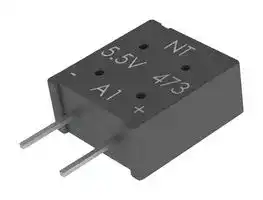
## Marking
**==> picture [202 x 134] intentionally omitted <==**
**----- Start of picture text -----**<br>
Negative Polarity Identification<br>Series<br>Name Trademark<br>Maximum<br>Nominal<br>Operating<br>Capacitance<br>Voltage<br>Polarity Polarity<br>(Negative) (Positive)<br>Date<br>Code<br>**----- End of picture text -----**<br>
## Packaging Quantities
|Part Number<br>~~a~~|Bulk Quantity per Box<br>Straight Lead<br>~~ee~~|Bulk Quantity per Box<br>L1 Lead Option<br>~~ee~~|Ammo Pack Quantity<br>~~ee~~|
|---|---|---|---|
|FM0H103ZF<br>~~a ~~|1,000pieces<br> ~~ee~~|1,000pieces<br>~~ee ~~|1,000pieces<br> ~~ee~~|
|FM0H223ZF|1,000pieces|1,000pieces|1,000pieces|
|FM0H473ZF<br>~~ee~~|1,000pieces<br>~~ee~~|1,000pieces<br>~~ee~~|1,000pieces<br>~~ee~~|
|FM0H104ZF<br>~~ee~~<br>~~a~~|1,000pieces<br>~~ee~~<br>|800pieces<br>~~ee~~<br>|1,000pieces<br>~~ee~~<br>|
|FM0H224ZF<br>~~ee~~<br>~~a~~|1,000pieces<br>~~ee~~<br>|800pieces<br>~~ee~~<br>|1,000pieces<br>~~ee~~<br>|
|FM0V473ZF<br>~~a~~|1,000pieces<br>|1,000pieces<br>|1,000pieces<br>|
|FM0V104ZF<br>~~ee~~|1,000pieces<br>~~ee~~|1,000pieces<br>~~ee~~|1,000pieces<br>~~ee~~|
|FM0V224ZF<br>~~ee~~<br>~~a~~|1,000pieces<br>~~ee~~<br>|800pieces<br>~~ee~~<br>|1,000pieces<br>~~ee~~<br>|
|FM0J473ZF<br>~~ee~~<br>~~a~~|1,000pieces<br>~~ee~~<br>|800pieces<br>~~ee~~<br>|1,000pieces<br>~~ee~~<br>|
|FME0H223ZF<br>~~a~~|1,000pieces<br>|1,000pieces<br>|1,000pieces<br>|
|FME0H473ZF<br>~~ee~~|1,000pieces<br>~~ee~~|1,000pieces<br>~~ee~~|1,000pieces<br>~~ee~~|
|FMR0H473ZF<br>~~ee~~<br>~~a~~|1,000pieces<br>~~ee~~<br>|1,000pieces<br>~~ee~~<br>|1,000pieces<br>~~ee~~<br>|
|FMR0H104ZF<br>~~ee~~<br>~~a~~|1,000pieces<br>~~ee~~<br>|1,000pieces<br>~~ee~~<br>|1,000pieces<br>~~ee~~<br>|
|FMR0V104ZF<br>~~a~~|1,000pieces<br>|800pieces<br>|1,000pieces<br>|
|FMR0V334ZF<br>~~ee~~|1,000pieces<br>~~ee~~|800pieces<br>~~ee~~|1,000pieces<br>~~ee~~|
|FMR0V474ZF<br>~~ee~~<br>~~a~~|400pieces<br>~~ee~~<br>|300pieces<br>~~ee~~<br>|400pieces<br>~~ee~~<br>|
|FMC0H473ZF<br>~~ee~~<br>~~a~~|1,000pieces<br>~~ee~~<br>|1,000pieces<br>~~ee~~<br>|1,000pieces<br>~~ee~~<br>|
|FMC0H104ZF<br>~~aee~~|1,000pieces<br>~~ee~~|1,000pieces<br>~~ee~~|1,000pieces<br>~~ee~~|
|FMC0H334ZF<br>~~ee~~|400pieces<br>~~ee~~|300pieces<br>~~ee~~|400pieces<br>~~ee~~|
S6012_FM (2026-03-19)
9 | YAGEOGroup.com
**Supercapacitors**
FM Series
## Ammo Pack Taping Format (Except FMC0H334ZFTP, FMR0V474ZFTP)
**==> picture [543 x 611] intentionally omitted <==**
**----- Start of picture text -----**<br>
|||||
|---|---|---|---|
|P2|P|∆h|
|b|c|
|–|+|–|+|
|P1|F|W4|t3|
|t2|
|P0|D0|t1|
|Ammo Pack Taping Specifications (Except FMC0H334ZFTP, FMR0V474ZFTP)|
|Item|Symbol|Dimensions (mm)|
|Component Height|a|11.5±0.5|
|Component Width|b|10.5±0.5|
|Component Thickness|c|Refer to “Dimensions” table|
|Lead-Wire Width|W4|0.5±0.1|
|Lead-Wire Thickness|t3|0.4±0.1|
|Component Pitch|P|12.7±1.0|
|Sprocket Hole Pitch|P0|12.7±0.3|
|Sprocket Hole Center to Lead Center|P1|3.85±0.7|
|Sprocket Hole Center to Component Center|P2|6.35±0.7|
|Lead Spacing|F|5.0±0.5|
|Component Alignment (side/side)|∆h|2.0 Maximum|
|Carrier Tape Width|W|18.0+1.0/−0.5|
|Hold-Down Tape Width|W0|12.5 Minimum|
|Sprocket Hole Position|W1|9.0±0.5|
|Hold-Down Tape Position|W2|3.0 Maximum|
|Height to Seating Plane (lead length)|H|16.0±0.5/18.0±0.5|
|Sprocket Hole Diameter|D0|ø 4.0±0.2|
|Carrier Tape Thickness|t1|0.7±0.2|
|Total Thickness (Carrier Tape, Hold-Down Tape and|
|Lead)|t2|1.5 Maximum|
|Cut Out Length|L|11.0 Maximum|
**----- End of picture text -----**<br>
S6012_FM (2026-03-19)
10 | YAGEOGroup.com
**Supercapacitors** FM Series
## Ammo Pack Taping Format (FMC0H334ZFTP, FMR0V474ZFTP)
**==> picture [386 x 203] intentionally omitted <==**
**----- Start of picture text -----**<br>
P2 P ∆h<br>b c<br>– + – +<br>P1 F W4 t3<br>t2<br>P0 D0 t1<br>a<br>W2<br>H<br>L<br>W1<br>W0<br>W<br>**----- End of picture text -----**<br>
## Ammo Pack Taping Specifications (FMC0H334ZFTP, FMR0V474ZFTP)
**==> picture [397 x 26] intentionally omitted <==**
**----- Start of picture text -----**<br>
Item Symbol Dimensions (mm)<br>**----- End of picture text -----**<br>
|Item|Symbol|Dimensions (mm)|
|---|---|---|
||||
|Component Height|a|15.0±0.5|
|Component Width|b|14.0±0.5|
|Component Thickness|c|9.0±0.5|
|Lead-Wire Width|W4|0.6±0.1|
|Lead-Wire Thickness|t3|0.6±0.1|
|Component Pitch|P|25.4±1.0|
|Sprocket Hole Pitch|P0|12.7±0.3|
|Sprocket Hole Center to Lead Center|P1|3.85±0.7|
|Sprocket Hole Center to Component Center|P2|6.35±0.7|
|Lead Spacing|F|5.0±0.5|
|Component Alignment (side/side)|∆h|2.0 Maximum|
|Carrier Tape Width|W|18.0+1.0/−0.5|
|Hold-Down Tape Width|W0|12.5 Minimum|
|Sprocket Hole Position|W1|9.0±0.5|
|Hold-Down Tape Position|W2|3.0 Maximum|
|Height to Seating Plane (lead length)|H|16.0±0.5/18.0±0.5|
|Sprocket Hole Diameter|D0|ø 4.0±0.2|
|Carrier Tape Thickness|t1|0.67±0.2|
|Total Thickness (Carrier Tape, Hold-Down Tape and<br>Lead)|t2|1.7 Maximum|
|Cut Out Length|L|11.0 Maximum|
S6012_FM (2026-03-19)
11 | YAGEOGroup.com
**Supercapacitors** FM Series
## Measurement Conditions
## Capacitance (Charge System)
Capacitance is calculated from expression (9) by measuring the charge time constant (τ) of the capacitor (C). Prior to measurement, the capacitor is discharged by shorting both pins of the device for at least 30 minutes. In addition, use the polarity indicator on the device to determine correct orientation of capacitor for charging.
**==> picture [174 x 113] intentionally omitted <==**
**----- Start of picture text -----**<br>
Capacitance: τ<br>(F) (9)<br>C = Rc<br>Switch<br>Rc<br>+<br>Eo C Vc<br>–<br>**----- End of picture text -----**<br>
Eo: 3.0 (V) Product with maximum operating voltage of 3.5 V 5.0 (V) Product with maximum operating voltage of 5.5 V 6.0 (V) Product with maximum operating voltage of 6.5 V 10.0 (V) Product with maximum operating voltage of 11 V 12.0 (V) Product with maximum operating voltage of 12 V τ: Time from start of charging until Vc becomes 0.632 Eo (V) (seconds) Rc: See table below (Ω).
Charge Resistor Selection Guide
**==> picture [543 x 335] intentionally omitted <==**
**----- Start of picture text -----**<br>
FY FM, FME FG, FC, FCS,<br>Cap FA FE FS FR FMC FGH FT<br>FYD FYH FMR FGR FCR<br>0.010 F – – – – – – 5,000 Ω – 5,000 Ω – – –<br>0.022 F 1,000 Ω – 1,000 Ω 2,000 Ω 2,000 Ω 2,000 Ω 2,000 Ω – 2,000 Ω – – Discharge<br>0.033 F – – – – – – Discharge – – – – –<br>0.047 F 1,000 Ω 1,000 Ω 1,000 Ω 2,000 Ω 1,000 Ω 1,000 Ω 2000 Ω 1,000 Ω 2,000 Ω – – –<br>0.10 F 510 Ω 510 Ω 510 Ω 1,000 Ω 510 Ω 1,000 Ω 1000 Ω 1,000 Ω 1,000 Ω Discharge 510 Ω Discharge<br>0.22 F 200 Ω 200 Ω 200 Ω 510 Ω 510 Ω 510 Ω 0H: Discharge – 1,000 Ω Discharge 200 Ω Discharge<br>0V: 1000 Ω<br>0.33 F – – – – – – – Discharge – – – –<br>0.47 F 100 Ω 100 Ω 100 Ω 200 Ω 200 Ω 200 Ω – – 1,000 Ω Discharge 100 Ω Discharge<br>1.0 F 51 Ω 51 Ω 100 Ω 100 Ω 100 Ω 100 Ω – – 510 Ω Discharge 100 Ω Discharge<br>1.4 F – – – 200 Ω – – – – – – – –<br>1.5 F – 51 Ω – – – – – – 510 Ω – – –<br>2.2 F – – – 100 Ω – – – – 200 Ω – 51 Ω –<br>2.7 F – – – – – – – – – – – –<br>3.3 F – – – – – – – – – – 51 Ω –<br>4.7 F – – – – – – – – 100 Ω – – –<br>5.0 F – – 100 Ω – – – – – – – – –<br>5.6 F – – – – – – – – – – 20 Ω –<br>10.0 F – – – – – – – – – – – –<br>22.0 F – – – – – – – – – – – –<br>50.0 F – – – – – – – – – – – –<br>100.0 F – – – – – – – – – – – –<br>200.0 F – – – – – – – – – – – –<br>**----- End of picture text -----**<br>
_*Capacitance values according to the constant current discharge method._
S6012_FM (2026-03-19)
12 | YAGEOGroup.com
**Supercapacitors** FM Series
## Measurement Conditions cont.
## Capacitance (Discharge System)
As shown in the diagram below, charging is performed for a duration of 30 minutes once the voltage of the capacitor terminal reaches 5.5 V. Then, use a constant current load device and measure the time for the terminal voltage to drop from 3.0 to 2.5 V upon discharge at 0.22 mA per 0.22 F, for example, and calculate the static capacitance according to the equation shown below.
_Note: The current value is 1 mA discharged per 1 F._
**==> picture [425 x 75] intentionally omitted <==**
**----- Start of picture text -----**<br>
(V)<br>0.22 mA (I)<br>SW A 5.5 V V 1 : 3.0 V<br>C = I ×V(T 1- 2-V 2T 1) (F) 5.5 V V C R VV 12 V 2 : 2.5 V<br>T 1 T 2 Time (seconds)<br>30 minutes<br>**----- End of picture text -----**<br>
## Capacitance (Discharge System, 3.5V, 3.6V)
As shown in the diagram below, charging is performed for a duration of 30 minutes once the voltage of the capacitor terminal reaches 3.5 V (3.6V). Then, use a constant current load device and measure the time for the terminal voltage to drop from 1.8 to 1.5 V upon discharge at 1.0 mA per 1.0F, for example, and calculate the static capacitance according to the equation shown below.
**==> picture [425 x 75] intentionally omitted <==**
**----- Start of picture text -----**<br>
(V)<br>SW 3.5 V<br>A (3.6 V) V 1 : 1.8 V<br>I × (T 2-T 1) 3.5 V VV 12 V 2 : 1.5 V<br>C = V 1-V 2 (F) (3.6 V) V C R<br>T 1 T 2 Time (seconds)<br>30 minutes<br>**----- End of picture text -----**<br>
## Equivalent Series Resistance (ESR)
ESR shall be calculated from the equation below.
**==> picture [285 x 71] intentionally omitted <==**
**----- Start of picture text -----**<br>
10mA<br>V C<br>ESR = ( Ω ) f:1kHz C V C<br>0.01<br>**----- End of picture text -----**<br>
S6012_FM (2026-03-19)
13 | YAGEOGroup.com
**Supercapacitors** FM Series
## Measurement Conditions cont.
## Current (at 30 minutes after charging)
In the following circuit, measure the voltage VR at both ends of the series resistor Rc after 30 minutes of applying a voltage to the capacitor C, and calculated from the following formula. (The voltage is applied at least 30 minutes later by shortcircuiting between the capacitor terminals).
Eo: 3.0 VDC (3.5 V type) 3.6 VDC (3.6 V type) 5.0 VDC (5.5 V type) 6.0 VDC (6.5 V type) 10.0 VDC (11 V type) 12.0 VDC (12 V type)
Rc: 1,000 Ω (0.01 F, 0.022 F, 0.047 F) 100 Ω (0.10 F, 0.22 F, 0.33 F, 0.47 F) 10 Ω (1.0 F, 1.4 F, 1.5 F, 2.2 F, 3.3 F, 4.7 F, 5.6 F) However, FS Seres 11 V type and 12 V type 100 Ω 0.47 F, 1.0 F 10 Ω 5.0 F
**==> picture [266 x 63] intentionally omitted <==**
**----- Start of picture text -----**<br>
V R SW<br>Current = RV C R (A) E O R C C+<br>-<br>**----- End of picture text -----**<br>
## Self-Discharge Characteristic (0H – 5.5 V Products)
The self-discharge characteristic is measured by charging a voltage of 5.0 VDC (charge protection resistance: 0 Ω) according to the capacitor polarity for 24 hours, then releasing between the pins for 24 hours and measuring the pin-topin voltage. The test should be carried out in an environment with an ambient temperature of 25° C or below and relative humidity of 70% RH or below. The soldering is checked.
## 4. Dismantling
There is a small amount of electrolyte stored within the capacitor. Do not attempt to dismantle as direct skin contact with the electrolyte will cause burning. This product should be treated as industrial waste and not is not to be disposed of by fi re.
S6012_FM (2026-03-19)
14 | YAGEOGroup.com
**Supercapacitors** FM Series
## Notes on Using Supercapacitors or Electric Double-Layer Capacitors (EDLCs)
## 1. Circuitry Design
## 1.1 Useful life
The FC Series Supercapacitor (EDLC) uses an electrolyte in a sealed container. Water in the electrolyte can evaporate while in use over long periods of time at high temperatures, thus reducing electrostatic capacity which in turn will create greater internal resistance. The characteristics of the supercapacitor can vary greatly depending on the environment in which it is used. Basic breakdown mode is an open mode due to increased internal resistance.
## 1.2 Fail rate in the field
Based on field data, the fail rate is calculated at approximately 0.006 Fit. We estimate that unreported failures are ten times this amount. Therefore, we assume that the fail rate is below 0.06 Fit.
## 1.3 Exceeding maximum usable voltage
Performance may be compromised and in some cases leakage or damage may occur if applied voltage exceeds maximum working voltage.
## 1.4 Use of capacitor as a smoothing capacitor (ripple absorption)
As supercapacitors contain a high level of internal resistance, they are not recommended for use as smoothing capacitors in electrical circuits. Performance may be compromised and, in some cases, leakage or damage may occur if a supercapacitor is used in ripple absorption.
## 1.5 Series connections
As applied voltage balance to each supercapacitor is lost when used in series connection, excess voltage may be applied to some supercapacitors, which will not only negatively affect its performance but may also cause leakage and/or damage. Allow ample margin for maximum voltage or attach a circuit for applying equal voltage to each supercapacitor (partial pressure resistor/voltage divider) when using supercapacitors in series connection. Also, arrange supercapacitors so that the temperature between each capacitor will not vary.
## 1.6 Case Polarity
The supercapacitor is manufactured so that the terminal on the outer case is negative (-). Align the (-) symbol during use. Even though discharging has been carried out prior to shipping, any residual electrical charge may negatively affect other parts.
## 1.7 Use next to heat emitters
Useful life of the supercapacitor will be significantly affected if used near heat emitting items (coils, power transistors and posistors, etc.) where the supercapacitor itself may become heated.
## 1.8 Usage environment
This device cannot be used in any acidic, alkaline or similar type of environment.
S6012_FM (2026-03-19)
15 | YAGEOGroup.com
**Supercapacitors**
FM Series
## Notes on Using Supercapacitors or Electric Double-Layer Capacitors (EDLCs) cont.
## 2. Mounting
## 2.1 Mounting onto a reflow furnace
Except for the FC series, it is not possible to mount this capacitor onto an IR / VPS reflow furnace. Do not immerse the capacitor into a soldering dip tank.
## 2.2 Flow soldering conditions
Keep solder under 260°C and soldering time to within 10 seconds when using the flow automatic soldering method. (Except for the FC and HV series)
## 2.3 Installation using a soldering iron
Care must be taken to prevent the soldering iron from touching other parts when soldering. Keep the tip of the soldering iron under 400°C and soldering time to within 3 seconds. Always make sure that the temperature of the tip is controlled. Internal capacitor resistance is likely to increase if the terminals are overheated.
## 2.4 Lead terminal processing
Do not attempt to bend or polish the capacitor terminals with sand paper, etc. Soldering may not be possible if the metallic plating is removed from the top of the terminals.
## 2.5 Cleaning, Coating, and Potting
Except for the FM series, cleaning, coating and potting must not be carried out. Consult KEMET if this type of procedure is necessary. Terminals should be dried at less than the maximum operating temperature after cleaning.
## 3. Storage
## 3.1 Temperature and humidity
Make sure that the supercapacitor is stored according to the following conditions: Temperature: 5 – 35°C (Standard 25°C), Humidity: 20 – 70% (Standard: 50%). Do not allow the build up of condensation through sudden temperature change.
## 3.2 Environment conditions
Make sure there are no corrosive gasses such as sulfur dioxide, as penetration of the lead terminals is possible. Always store this item in an area with low dust and dirt levels. Make sure that the packaging will not be deformed through heavy loading, movement and/or knocks. Keep out of direct sunlight and away from radiation, static electricity and magnetic fields.
## 3.3 Maximum storage period
This item may be stored up to one year from the date of delivery if stored at the conditions stated above.
## Dismantling
There is a small amount of electrolyte stored within the capacitor. Do not attempt to dismantle as direct skin contact with the electrolyte will cause burning. This product should be treated as industrial waste and not is not to be disposed of by fire.
S6012_FM (2026-03-19)
16 | YAGEOGroup.com
**Supercapacitors** FM Series
##
## Disclaimer
YAGEO Corporation and its affi liates do not recommend the use of commercial or automotive grade products for high reliability applications or manned space fl ight.
All product specifi cations, statements, information and data (collectively, the “Information”) in this datasheet are subject to change. The customer is responsible for checking and verifying the extent to which the Information contained in this publication is applicable to an order at the time the order is placed. All Information given herein is believed to be accurate and reliable, but it is presented without guarantee, warranty, or responsibility of any kind, expressed or implied.
Statements of suitability for certain applications are based on KEMET Electronics Corporation’s (“KEMET”) knowledge of typical operating conditions for such applications, but are not intended to constitute – and KEMET specifi cally disclaims – any warranty concerning suitability for a specifi c customer application or use. The Information is intended for use only by customers who have the requisite experience and capability to determine the correct products for their application. Any technical advice inferred from this Information or otherwise provided by KEMET with reference to the use of KEMET’s products is given gratis, and KEMET assumes no obligation or liability for the advice given or results obtained.
Although KEMET designs and manufactures its products to the most stringent quality and safety standards, given the current state of the art, isolated component failures may still occur. Accordingly, customer applications which require a high degree of reliability or safety should employ suitable designs or other safeguards (such as installation of protective circuitry or redundancies) in order to ensure that the failure of an electrical component does not result in a risk of personal injury or property damage.
Although all product–related warnings, cautions and notes must be observed, the customer should not assume that all safety measures are indicated or that other measures may not be required.
When providing KEMET products and technologies contained herein to other countries, the customer must abide by the procedures and provisions stipulated in all applicable export laws and regulations, including without limitation the International Traffi c in Arms Regulations (ITAR), the US Export Administration Regulations (EAR) and the Japan Foreign Exchange and Foreign Trade Act.
_KEMET is a registered trademark of KEMET Electronics Corporation._
S6012_FM (2026-03-19)
17 | YAGEOGroup.com
Updated at April 29, 2026
With over a century of technological innovation, Kemet is a premier global supplier of electronic components, renowned for providing the industry's broadest selection of capacitor technologies. Their high-reliability solutions are trusted in the world's most demanding applications, ranging from spacecraft and life-saving medical devices to everyday consumer electronics and rapidly expanding industrial sectors. Our extensive Kemet portfolio is heavily focused on their industry-leading passive components, particularly their comprehensive range of capacitors. We offer thousands of options to suit diverse design requirements, including high-performance film capacitors, robust aluminium electrolytic capacitors, and advanced polymer capacitors. For specialised applications, a wide selection of RF capacitors and high-capacitance supercapacitors is also available. Beyond capacitors, Kemet excels in electromagnetic compatibility (EMC) and power management solutions. Our selection features a vast array of common mode chokes, power line filters, and shielding materials designed to ensure signal integrity and regulatory compliance. Additionally, we carry a strong lineup of Kemet power and toroidal inductors, alongside circuit protection devices such as TVS varistors, signal relays, and precision sensors, providing a versatile foundation for modern electronic design.
About Novapart
Novapart is a B2B electronic component broker specialising in stock shortages and cost reduction. We source hard-to-find parts and identify compliant alternatives across a catalogue of 410,000+ components from 500+ manufacturers.
Learn more →Stock Shortage Specialist
When a component is unavailable, discontinued or has an unacceptable lead time, we tap into our network of vetted European and Asian distributors to source what you need — without compromising on quality or traceability.
Request a quote →Compliant Alternatives
We identify pin-to-pin, electrically equivalent substitutes that meet the same certifications (RoHS, AEC-Q100, REACH) as your original specification — validated against datasheets, not just part numbers. Often at a lower cost.
BOM Analysis service →