
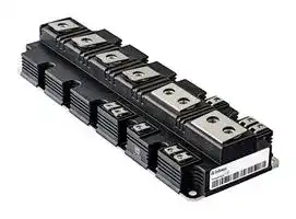


FF1500R17IP5BPSA1
IGBT Module, Dual, 1.5 kA, 1.75 V, 175 °C, Module
- Manufacturer: INFINEON
- Product type: IGBT Modules
- SVHC: No SVHC (25-Jun-2025)
- Product Range: PrimePACK 3+B
- IGBT Technology: IGBT 5 [Trench/Field Stop]
- IGBT Termination: Stud
- Power Dissipation: -
- IGBT Configuration: Dual
- Transistor Mounting: Panel
- DC Collector Current: 1.5kA
- Power Dissipation Pd: -
- Transistor Case Style: Module
- Operating Temperature Max: 175°C
- Junction Temperature Tj Max: 175°C
- Continuous Collector Current: 1.5kA
- Collector Emitter Voltage Max: 1.7kV
- Collector Emitter Voltage V(br)ceo: 1.7kV
- Collector Emitter Saturation Voltage: 1.75V
- Collector Emitter Saturation Voltage Vce(on): 1.75V
| Delivery and price | |
|---|---|
| Units per pack | 1 |
| Price | 618.25 € |
| Current stock | 10+ |
| Lead time | 30 days |
## FF1500R17IP5

VCES = 1700V IC nom = 1500A / ICRM = 3000A

- 潜在应用 • 大功率变流器

- • 牵引变流器 • 电机传动 • 风力发电机

•

-

-

-

## 电气特性

- T vj op =

- • 1K V CEsat

- 低开关损耗

-

- 高电流密度

- T vj op =

- • Low V CEsat

-

-

-

## 机械特性

-

- 高功率密度

- • 高功率循环和温度循环能力

- • 高爬电距离和电气间隙

-

-

-

-

**Digit**

Datasheet www.infineon.com

2017-09-19

FF1500R17IP5

**==> picture [86 x 38] intentionally omitted <==**

## IGBT,�逆变器�/�IGBT,Inverter 最大额定值�/�Maximum�Rated�Values

|集电极-发射极电压<br>Collector-emittervoltage|Tvj= 25°C|VCES|1700|1700||V|
|---|---|---|---|---|---|---|
|连续集电极直流电流<br>ContinuousDCcollectorcurrent|TC= 90°C, Tvj max= 175°C|IC nom|1500|||A|
|集电极重复峰值电流<br>Repetitivepeakcollectorcurrent|tP= 1 ms|ICRM|3000|||A|
|栅极-发射极峰值电压<br>Gate-emitterpeakvoltage||VGES|+/-20|||V|
|特征值/CharacteristicValues|||min.|typ.|max.||
|集电极-发射极饱和电压<br>Collector-emittersaturationvoltage|IC= 1500 A, VGE= 15 V<br>IC= 1500 A, VGE= 15 V<br>IC= 1500 A, VGE= 15 V<br>Tvj= 25°C<br>Tvj= 125°C<br>Tvj= 175°C|VCE sat||1,75<br>2,10<br>2,30|2,20<br>2,65<br>2,90|V<br>V<br>V|
|栅极阈值电压<br>Gatethresholdvoltage|IC= 54,0 mA, VCE= VGE, Tvj= 25°C|VGEth|5,35|5,80|6,25|V|
|栅极电荷<br>Gatecharge|VGE= -15 V ... +15 V, VCE= 900V|QG||7,50||µC|
|内部栅极电阻<br>Internalgateresistor|Tvj= 25°C|RGint||1,0||Ω|
|输入电容<br>Inputcapacitance|f = 1 MHz, Tvj= 25°C, VCE= 25 V, VGE= 0 V|Cies||88,0||nF|
|反向传输电容<br>Reversetransfercapacitance|f = 1 MHz, Tvj= 25°C, VCE= 25 V, VGE= 0 V|Cres||2,70||nF|
|集电极-发射极截止电流<br>Collector-emittercut-offcurrent|VCE= 1700 V, VGE= 0 V, Tvj= 25°C|ICES|||5,0|mA|
|栅极-发射极漏电流<br>Gate-emitterleakagecurrent|VCE= 0 V, VGE= 20 V, Tvj= 25°C|IGES|||400|nA|
|开通延迟时间(电感负载)<br>Turn-ondelaytime,inductiveload|IC= 1500 A, VCE= 900 V<br>VGE= ±15 V<br>RGon= 0,51Ω<br>Tvj= 25°C<br>Tvj= 125°C<br>Tvj= 175°C|td on||0,30<br>0,31<br>0,32||µs<br>µs<br>µs|
|上升时间(电感负载)<br>Risetime,inductiveload|IC= 1500 A, VCE= 900 V<br>VGE= ±15 V<br>RGon= 0,51Ω<br>Tvj= 25°C<br>Tvj= 125°C<br>Tvj= 175°C|tr||0,15<br>0,16<br>0,16||µs<br>µs<br>µs|
|关断延迟时间(电感负载)<br>Turn-offdelaytime,inductiveload|IC= 1500 A, VCE= 900 V<br>VGE= ±15 V<br>RGoff= 0,82Ω<br>Tvj= 25°C<br>Tvj= 125°C<br>Tvj= 175°C|td off||0,66<br>0,74<br>0,80||µs<br>µs<br>µs|
|下降时间(电感负载)<br>Falltime,inductiveload|IC= 1500 A, VCE= 900 V<br>VGE= ±15 V<br>RGoff= 0,82Ω<br>Tvj= 25°C<br>Tvj= 125°C<br>Tvj= 175°C|tf||0,11<br>0,16<br>0,17||µs<br>µs<br>µs|
|开通损耗能量(每脉冲)<br>Turn-onenergylossperpulse|IC= 1500 A, VCE= 900 V, LS= 30 nH<br>VGE= ±15 V, di/dt = 8550 A/µs (Tvj= 175°C)<br>RGon= 0,51Ω<br>Tvj= 25°C<br>Tvj= 125°C<br>Tvj= 175°C|Eon||335<br>500<br>595||mJ<br>mJ<br>mJ|
|关断损耗能量(每脉冲)<br>Turn-offenergylossperpulse|IC= 1500 A, VCE= 900 V, LS= 30 nH<br>VGE= ±15 V, du/dt = 2750 V/µs (Tvj= 175°C)<br>RGoff= 0,82Ω<br>Tvj= 25°C<br>Tvj= 125°C<br>Tvj= 175°C|Eoff||330<br>465<br>545||mJ<br>mJ<br>mJ|
|短路数据<br>SCdata|VGE ≤15 V, VCC= 1000 V<br>VCEmax= VCES-LsCE·di/dt<br>Tvj= 175°C<br>tP ≤10 µs,|ISC||6000||A|
|结-外壳热阻<br>Thermalresistance,junctiontocase|每个IGBT/perIGBT|RthJC|||19,0|K/kW|
|外壳-散热器热阻<br>Thermalresistance,casetoheatsink|每个IGBT/perIGBT<br>λPaste=1W/(m·K)/λgrease=1W/(m·K)|RthCH||15,5||K/kW|
|在开关状态下温度<br>Temperatureunderswitchingconditions||Tvj op|-40||175|°C|


2

V�3.0 2017-09-19

Datasheet

## FF1500R17IP5

**==> picture [86 x 38] intentionally omitted <==**

## 二极管,逆变器�/�Diode,�Inverter 最大额定值�/�Maximum�Rated�Values

|反向重复峰值电压<br>Repetitivepeakreversevoltage|Tvj= 25°C|VRRM|1700|1700||V|
|---|---|---|---|---|---|---|
|连续正向直流电流<br>ContinuousDCforwardcurrent||IF|1500|||A|
|正向重复峰值电流<br>Repetitivepeakforwardcurrent|tP= 1 ms|IFRM|3000|||A|
|I2t-值<br>I²t-value|VR= 0 V, tP= 10 ms, Tvj= 125°C<br>VR= 0 V, tP= 10 ms, Tvj= 175°C|I²t|580<br>485|||kA²s<br>kA²s|
|最大损耗功率<br>Maximumpowerdissipation|Tvj= 175°C|PRQM|1500|||kW|
|特征值/CharacteristicValues|||min.|typ.|max.||
|正向电压<br>Forwardvoltage|IF= 1500 A, VGE= 0 V<br>IF= 1500 A, VGE= 0 V<br>IF= 1500 A, VGE= 0 V<br>Tvj= 25°C<br>Tvj= 125°C<br>Tvj= 175°C|VF||1,75<br>1,70<br>1,70|2,10<br>2,05<br>2,05|V<br>V<br>V|
|反向恢复峰值电流<br>Peakreverserecoverycurrent|IF= 1500 A, - diF/dt = 8550 A/µs (Tvj=175°C)<br>VR= 900 V<br>VGE= -15 V<br>Tvj= 25°C<br>Tvj= 125°C<br>Tvj= 175°C|IRM||1250<br>1450<br>1550||A<br>A<br>A|
|恢复电荷<br>Recoveredcharge|IF= 1500 A, - diF/dt = 8550 A/µs (Tvj=175°C)<br>VR= 900 V<br>VGE= -15 V<br>Tvj= 25°C<br>Tvj= 125°C<br>Tvj= 175°C|Qr||325<br>550<br>700||µC<br>µC<br>µC|
|反向恢复损耗(每脉冲)<br>Reverserecoveryenergy|IF= 1500 A, - diF/dt = 8550 A/µs (Tvj=175°C)<br>VR= 900 V<br>VGE= -15 V<br>Tvj= 25°C<br>Tvj= 125°C<br>Tvj= 175°C|Erec||185<br>325<br>425||mJ<br>mJ<br>mJ|
|结-外壳热阻<br>Thermalresistance,junctiontocase|每个二极管/perdiode|RthJC|||35,0|K/kW|
|外壳-散热器热阻<br>Thermalresistance,casetoheatsink|每个二极管/perdiode<br>λPaste=1W/(m·K)/λgrease=1W/(m·K)|RthCH||18,5||K/kW|
|在开关状态下温度<br>Temperatureunderswitchingconditions||Tvj op|-40||175|°C|
|负温度系数热敏电阻/NTC-Thermistor<br>特征值/CharacteristicValues|||min.|typ.|max.||
|额定电阻值<br>Ratedresistance|TNTC= 25°C|R25||5,00||kΩ|
|R100偏差<br>DeviationofR100|TNTC= 100°C, R100= 493Ω|∆R/R|-5||5|%|
|耗散功率<br>Powerdissipation|TNTC= 25°C|P25|||20,0|mW|
|B-值<br>B-value|R2= R25exp [B25/50(1/T2- 1/(298,15 K))]|B25/50||3375||K|
|B-值<br>B-value|R2= R25exp [B25/80(1/T2- 1/(298,15 K))]|B25/80||3411||K|
|B-值<br>B-value|R2= R25exp [B25/100(1/T2- 1/(298,15 K))]|B25/100||3433||K|


根据应用手册标定 Specification�according�to�the�valid�application�note.

3

V�3.0 2017-09-19

Datasheet

## FF1500R17IP5

**==> picture [86 x 38] intentionally omitted <==**

## 模块�/�Module

|模块/Module|||||||
|---|---|---|---|---|---|---|
|绝缘测试电压<br>Isolationtestvoltage|RMS, f = 50 Hz, t = 1 min.|VISOL|4,0<br>|||kV|
|模块基板材料<br>Materialofmodulebaseplate|||Cu||||
|爬电距离<br>Creepagedistance|端子至散热器/terminaltoheatsink<br>端子至端子/terminaltoterminal||33,0<br>33,0<br>|||mm|
|电气间隙<br>Clearance|端子至散热器/terminaltoheatsink<br>端子至端子/terminaltoterminal||19,0<br>19,0<br>|||mm|
|相对电痕指数<br>Comperativetrackingindex||CTI||> 400|||
||||min.|typ.|max.||
|杂散电感,模块<br>Strayinductancemodule||LsCE||10||nH|
|模块引线电阻,端子-芯片<br>Moduleleadresistance,terminals-chip|TC=25°C,每个开关/perswitch|RCC'+EE'<br>RAA'+CC'||0,10<br>0,09||mΩ|
|储存温度<br>Storagetemperature||Tstg|-40||150|°C|
|模块安装的安装扭距<br>Mountingtorqueformodulmounting|螺丝M5根据相应的应用手册进行安装<br>ScrewM5-Mountingaccordingtovalidapplicationnote|M|3,00||6,00|Nm|
|端子联接扭距<br>Terminalconnectiontorque|螺丝M4根据相应的应用手册进行安装<br>ScrewM4-Mountingaccordingtovalidapplicationnote<br>螺丝M8根据相应的应用手册进行安装<br>ScrewM8-Mountingaccordingtovalidapplicationnote|M|1,8<br>8,0|-<br>-|2,1<br>10|Nm<br>Nm|
|重量<br>Weight||G||1400||g|


Höchstzulässige Bodenplattenbetriebstemperatur   TBPmax = 150°C Maximum baseplate operation temperature             TBPmax = 150°C

V�3.0 2017-09-19

Datasheet

4

FF1500R17IP5

**==> picture [86 x 38] intentionally omitted <==**

输出特性�IGBT,�逆变器�(典型) **output�characteristic�IGBT,Inverter�(typical)** IC�=�f�(VCE) VGE�=�15�V

输出特性�IGBT,�逆变器�(典型) **output�characteristic�IGBT,Inverter�(typical)** IC�=�f�(VCE) Tvj�=�175°C

**==> picture [484 x 282] intentionally omitted <==**

**----- Start of picture text -----**<br>
3000 3000<br>2800 TTvjvj = 25°C = 125°C 2800 VVGEGE = 20V = 15V<br>Tvj = 175°C VGE = 12V<br>2600 2600 V GE  = 10V<br>VGE = 9V<br>2400 2400 V GE  = 8V<br>2200 2200<br>2000 2000<br>1800 1800<br>1600 1600<br>1400 1400<br>1200 1200<br>1000 1000<br>800 800<br>600 600<br>400 400<br>200 200<br>0 0<br>0,0 0,4 0,8 1,2 1,6 2,0 2,4 2,8 3,2 3,6 0,0 0,5 1,0 1,5 2,0 2,5 3,0 3,5 4,0 4,5 5,0 5,5 6,0<br>VCE [V] VCE [V]<br> [A]  [A]<br>IC IC<br>**----- End of picture text -----**<br>


传输特性�IGBT,�逆变器�(典型) **transfer�characteristic�IGBT,Inverter�(typical)** IC�=�f�(VGE) VCE�=�20�V

**==> picture [236 x 282] intentionally omitted <==**

**----- Start of picture text -----**<br>
3000<br>2800 TTvjvj = 25°C = 125°C<br>Tvj = 175°C<br>2600<br>2400<br>2200<br>2000<br>1800<br>1600<br>1400<br>1200<br>1000<br>800<br>600<br>400<br>200<br>0<br>5 6 7 8 9 10 11 12<br>VGE [V]<br> [A]<br>IC<br>**----- End of picture text -----**<br>


开关损耗�IGBT,�逆变器�(典型) **switching�losses�IGBT,Inverter�(typical)**

Eon�=�f�(IC),�Eoff�=�f�(IC)

VGE�=�±15�V,�RGon�=�0.51� Ω ,�RGoff�=�0.82� Ω ,�VCE�=�900�V

**==> picture [240 x 282] intentionally omitted <==**

**----- Start of picture text -----**<br>
1800<br>Eon, Tvj = 125°C<br>1600 E E on off , T , T vj vj  = 175°C  = 125 ° C<br>Eoff, Tvj = 175°C<br>1400<br>1200<br>1000<br>800<br>600<br>400<br>200<br>0<br>0 500 1000 1500 2000 2500 3000<br>IC [A]<br>E [mJ]<br>**----- End of picture text -----**<br>


V�3.0 2017-09-19

Datasheet

5

FF1500R17IP5

**==> picture [485 x 309] intentionally omitted <==**

**----- Start of picture text -----**<br>
Eon =f(R),E G off =f(R G) ZthJC =f (t)<br>VGE =+15V,1 C =1500A,V CE =900V<br>2200 100<br>Eon, Tvj = 125°C ZthJC : IGBT<br>2000 EEonoff,, T Tvvjj = 175°C = 125°C<br>a Eoff, Tvj = 175°C Se<br>1800<br>| Sati stati nih aii<br>y a a<br>1600<br>10<br>1400 “aLY eePeOTT<br>1200<br>1000 - aaa aSAAeee<br>800<br>1<br>600 HPAL za a a<br>/ PE A<br>400<br>i: 1 2 3 4<br>ri[K/kW]: 0,524 2,36 15 1,16<br>200 τ i[s]: 0,0009 0,012 0,0503 1,85<br>a |<br>0 0,1 PUTT VET PTT<br>0,0 0,5 1,0 1,5 2,0 2,5 3,0 3,5 4,0 4,5 5,0 0,001 0,01 0,1 1 10<br>RG [ Ω ] t [s]<br> [K/kW]<br>E [mJ]<br>thJC<br>Z<br>**----- End of picture text -----**<br>


**==> picture [486 x 319] intentionally omitted <==**

**----- Start of picture text -----**<br>
I reverse C CE bias )  safe operating area IGBT,Inverter (RBSOA) forward IF F) characteristic of Diode, Inverter (typical)<br>VGE SVR Goff =0.82 Ω ,T vj =175°C a<br>3600 3000<br>IICC, Modul, Chip 2800 TTvjvj = 25°C = 125°C<br>2600 Tvj = 175°C Ul<br>3000<br>= : 2400 et]a<br>2200<br>2400 CELL 2000 FREER<br>1800<br>1600<br>1800<br>1400<br>1200<br>1200 1000<br>e/<br>800<br>600<br>600<br>400<br>200 fe<br>0 0 nae Zeaneeeee<br>0 200 400 600 800 1000 1200 1400 1600 1800 0,0 0,2 0,4 0,6 0,8 1,0 1,2 1,4 1,6 1,8 2,0 2,2 2,4<br>VCE  [V] VF [V]<br> [A]  [A]<br>IC IF<br>**----- End of picture text -----**<br>


6

Datasheet

2017-09-19

FF1500R17IP5

**==> picture [489 x 656] intentionally omitted <==**

**----- Start of picture text -----**<br>
Erec =f(I F) Erec =f(R G)<br>RGon b51 Ω ,V CE =900V IF = 1600 A, V CE = 900 V<br>600 500<br>Erec, Tvj = 125°C Erec, Tvj = 125°C<br>Erec, Tvj = 175°C Erec, Tvj = 175°C<br>450<br>500<br>400<br>350<br>400<br>300<br>300 250<br>200<br>200 / i NERS: tr<br>jo N<br>150<br>/<br>/<br>100<br>100<br>50<br>A<br>0 0<br>0 500 1000 1500 2000 2500 3000 0,0 0,5 1,0 1,5 2,0 2,5 3,0 3,5 4,0 4,5 5,0<br>IF [A] RG [ Ω ]<br>transientBANAthermalRS impedanceees Diode, Inverter safeREToperationK RESarea wweDiode,(SOA)Inverter (SOA)<br>ZthJC =f(t® IR =f(V R)<br>Tvj = Ty5%c<br>100 3300<br>ZthJC : Diode IR, Modul<br>Te 3000<br>2700<br>a a | \<br>CCN<br>2400<br>TN eo<br>2100<br>1800<br>10<br>1500<br>1200<br>900<br>600<br>i: 1 2 3 4<br>ri[K/kW]: 2,02 9,55 20,7 2,7<br>τ i[s]: 0,0009 0,0172 0,0659 1,44 300<br>1 eee 0 PPE EE<br>0,001 0,01 0,1 1 10 0 200 400 600 800 1000 1200 1400 1600 1800<br>t [s] VR [V]<br>E [mJ] E [mJ]<br> [K/kW]thJC  [A]IR<br>Z<br>**----- End of picture text -----**<br>


Datasheet

7

2017-09-19

FF1500R17IP5

**==> picture [86 x 38] intentionally omitted <==**

## 负温度系数热敏电阻�温度特性 **NTC-Thermistor-temperature�characteristic�(typical)** R�=�f�(T)

**==> picture [240 x 282] intentionally omitted <==**

**----- Start of picture text -----**<br>
100000<br>Rtyp<br>10000<br>1000<br>100<br>0 25 50 75 100 125 150<br>TC [°C]<br>] Ω<br>R[<br>**----- End of picture text -----**<br>


8

V�3.0 2017-09-19

Datasheet

FF1500R17IP5

**==> picture [86 x 38] intentionally omitted <==**

## 接线图�/�Circuit�diagram

**==> picture [99 x 145] intentionally omitted <==**

## 封装尺寸�/�Package�outlines

**==> picture [494 x 324] intentionally omitted <==**

**----- Start of picture text -----**<br>
36 [�] [0,2]  (2x) 8 [�] [0,1]  (8x) 18 [�] [0,2]  (4x)<br>250 [�] [1]<br>A<br>224<br>187<br>recommended design height lower side 150<br>bus bar to baseplate 113<br>76<br>38,25 [�] [0,25] screwing depthmax. 8mm (8x) 24 58 M8 (8x) � � 0,8 A B C � 5,5 -0,2 (14x) � � 0,5 A B C<br>7,5 + 0,5 6 8x 14x<br>max. 3<br>screwing depth<br>max. 16mm (8x)<br>max. 2 26 [�] [0,25] B 14( � 5,5) M4 (8x) � 8x � 0,8 A B C ( � 5,5) C<br>recommended design height lower side 25<br>PCB to baseplate 39<br>64<br>78<br>92<br>103<br>117<br>156<br>195<br>234<br>10 (6x)<br>23,60,3  � 73 890,5  �<br>37 39<br>0,3  �  (2x)  (2x)<br>3,8 (8x) 20,6 0,3  � 0,3  �<br>25,1 22,1<br> (8x)<br>11,80,3  �<br>**----- End of picture text -----**<br>


9

V�3.0 2017-09-19

Datasheet

## Trademarks

## 重要提示

本文档所提供的任何信息绝不应当被视为针对任何条件或者品质而做出的保证(质量保证)。英飞凌对于本文档中所提及的任何事例、 提示或者任何特定数值及/或任何关于产品应用方面的信息均在此明确声明其不承担任何保证或者责任,包括但不限于其不侵犯任何 第三方知识产权的保证均在此排除。

此外,本文档所提供的任何信息均取决于客户履行本文档所载明的义务和客户遵守适用于客户产品以及与客户对于英飞凌产品的应用 所相关的任何法律要求、规范和标准。

本文档所含的数据仅供经过专业技术培训的人员使用。客户自身的技术部门有义务对于产品是否适宜于其预期的应用和针对该等应用 而言本文档中所提供的信息是否充分自行予以评估。 如需产品、技术、交付条款和条件以及价格等进一步信息,请向离您最近的英飞凌科技办公室接洽(www.infineon.com)。

## 警告事项

由于技术所需产品可能含有危险物质。如需了解该等物质的类型,请向离您最近的英飞凌科技办公室接洽。 除非由经英飞凌科技授权代表签署的书面文件中做出另行明确批准的情况外,英飞凌科技的产品不应当被用于任何一项一旦产品失效 或者产品使用的后果可被合理地预料到可能导致人身伤害的任何应用领域。

## WARNINGS
Updated at April 28, 2026
Infineon Technologies is a globally recognized leader in semiconductor solutions, renowned for driving innovation in power management, energy efficiency, and modern mobility. With a strong legacy of engineering excellence, the company provides highly reliable components designed to meet the rigorous demands of industrial, automotive, and advanced commercial applications. The core of our Infineon portfolio is centered on their industry-leading discrete semiconductors. We offer an extensive selection of single and dual MOSFETs, alongside a robust range of single IGBTs and advanced IGBT modules. These flagship power transistors are essential for high-efficiency power conversion and motor control, providing engineers with superior thermal performance and minimized switching losses. Beyond advanced field-effect transistors, the selection includes a comprehensive array of diodes and rectifiers, heavily featuring Schottky diodes, as well as fast-recovery and RF/PIN diodes. This power foundation is further supported by bipolar transistors, intelligent power modules, and thyristor SCR modules, delivering the critical building blocks required for complex power system designs. To support broader system integration, the portfolio also encompasses specialized solutions such as solid-state relays, AC/DC LED driver ICs, and Bluetooth communications modules. From high-power industrial rectifiers to wireless connectivity adapters, Infineon equips designers with the precision components needed to build efficient, scalable, and fully connected electronic systems.
About Novapart
Novapart is a B2B electronic component broker specialising in stock shortages and cost reduction. We source hard-to-find parts and identify compliant alternatives across a catalogue of 410,000+ components from 500+ manufacturers.
Learn more →Stock Shortage Specialist
When a component is unavailable, discontinued or has an unacceptable lead time, we tap into our network of vetted European and Asian distributors to source what you need — without compromising on quality or traceability.
Request a quote →Compliant Alternatives
We identify pin-to-pin, electrically equivalent substitutes that meet the same certifications (RoHS, AEC-Q100, REACH) as your original specification — validated against datasheets, not just part numbers. Often at a lower cost.
BOM Analysis service →